WO2021187328A1 - 保護カバー部材及び部材供給用シート - Google Patents
保護カバー部材及び部材供給用シート Download PDFInfo
- Publication number
- WO2021187328A1 WO2021187328A1 PCT/JP2021/009881 JP2021009881W WO2021187328A1 WO 2021187328 A1 WO2021187328 A1 WO 2021187328A1 JP 2021009881 W JP2021009881 W JP 2021009881W WO 2021187328 A1 WO2021187328 A1 WO 2021187328A1
- Authority
- WO
- WIPO (PCT)
- Prior art keywords
- adhesive layer
- sensitive adhesive
- pressure
- protective cover
- cover member
- Prior art date
- Legal status (The legal status is an assumption and is not a legal conclusion. Google has not performed a legal analysis and makes no representation as to the accuracy of the status listed.)
- Ceased
Links
Images


Classifications
-
- C—CHEMISTRY; METALLURGY
- C09—DYES; PAINTS; POLISHES; NATURAL RESINS; ADHESIVES; COMPOSITIONS NOT OTHERWISE PROVIDED FOR; APPLICATIONS OF MATERIALS NOT OTHERWISE PROVIDED FOR
- C09J—ADHESIVES; NON-MECHANICAL ASPECTS OF ADHESIVE PROCESSES IN GENERAL; ADHESIVE PROCESSES NOT PROVIDED FOR ELSEWHERE; USE OF MATERIALS AS ADHESIVES
- C09J183/00—Adhesives based on macromolecular compounds obtained by reactions forming in the main chain of the macromolecule a linkage containing silicon, with or without sulfur, nitrogen, oxygen, or carbon only; Adhesives based on derivatives of such polymers
- C09J183/04—Polysiloxanes
-
- B—PERFORMING OPERATIONS; TRANSPORTING
- B81—MICROSTRUCTURAL TECHNOLOGY
- B81B—MICROSTRUCTURAL DEVICES OR SYSTEMS, e.g. MICROMECHANICAL DEVICES
- B81B7/00—Microstructural systems ; Auxiliary parts of microstructural devices or systems
- B81B7/0032—Packages or encapsulation
- B81B7/0035—Packages or encapsulation for maintaining a controlled atmosphere inside of the chamber containing the MEMS
- B81B7/0038—Packages or encapsulation for maintaining a controlled atmosphere inside of the chamber containing the MEMS using materials for controlling the level of pressure, contaminants or moisture inside of the package, e.g. getters
-
- C—CHEMISTRY; METALLURGY
- C09—DYES; PAINTS; POLISHES; NATURAL RESINS; ADHESIVES; COMPOSITIONS NOT OTHERWISE PROVIDED FOR; APPLICATIONS OF MATERIALS NOT OTHERWISE PROVIDED FOR
- C09J—ADHESIVES; NON-MECHANICAL ASPECTS OF ADHESIVE PROCESSES IN GENERAL; ADHESIVE PROCESSES NOT PROVIDED FOR ELSEWHERE; USE OF MATERIALS AS ADHESIVES
- C09J7/00—Adhesives in the form of films or foils
- C09J7/20—Adhesives in the form of films or foils characterised by their carriers
- C09J7/29—Laminated material
-
- C—CHEMISTRY; METALLURGY
- C09—DYES; PAINTS; POLISHES; NATURAL RESINS; ADHESIVES; COMPOSITIONS NOT OTHERWISE PROVIDED FOR; APPLICATIONS OF MATERIALS NOT OTHERWISE PROVIDED FOR
- C09J—ADHESIVES; NON-MECHANICAL ASPECTS OF ADHESIVE PROCESSES IN GENERAL; ADHESIVE PROCESSES NOT PROVIDED FOR ELSEWHERE; USE OF MATERIALS AS ADHESIVES
- C09J7/00—Adhesives in the form of films or foils
- C09J7/30—Adhesives in the form of films or foils characterised by the adhesive composition
- C09J7/38—Pressure-sensitive adhesives [PSA]
-
- C—CHEMISTRY; METALLURGY
- C08—ORGANIC MACROMOLECULAR COMPOUNDS; THEIR PREPARATION OR CHEMICAL WORKING-UP; COMPOSITIONS BASED THEREON
- C08G—MACROMOLECULAR COMPOUNDS OBTAINED OTHERWISE THAN BY REACTIONS ONLY INVOLVING UNSATURATED CARBON-TO-CARBON BONDS
- C08G77/00—Macromolecular compounds obtained by reactions forming a linkage containing silicon with or without sulfur, nitrogen, oxygen or carbon in the main chain of the macromolecule
- C08G77/04—Polysiloxanes
- C08G77/12—Polysiloxanes containing silicon bound to hydrogen
-
- C—CHEMISTRY; METALLURGY
- C08—ORGANIC MACROMOLECULAR COMPOUNDS; THEIR PREPARATION OR CHEMICAL WORKING-UP; COMPOSITIONS BASED THEREON
- C08G—MACROMOLECULAR COMPOUNDS OBTAINED OTHERWISE THAN BY REACTIONS ONLY INVOLVING UNSATURATED CARBON-TO-CARBON BONDS
- C08G77/00—Macromolecular compounds obtained by reactions forming a linkage containing silicon with or without sulfur, nitrogen, oxygen or carbon in the main chain of the macromolecule
- C08G77/04—Polysiloxanes
- C08G77/20—Polysiloxanes containing silicon bound to unsaturated aliphatic groups
-
- C—CHEMISTRY; METALLURGY
- C09—DYES; PAINTS; POLISHES; NATURAL RESINS; ADHESIVES; COMPOSITIONS NOT OTHERWISE PROVIDED FOR; APPLICATIONS OF MATERIALS NOT OTHERWISE PROVIDED FOR
- C09J—ADHESIVES; NON-MECHANICAL ASPECTS OF ADHESIVE PROCESSES IN GENERAL; ADHESIVE PROCESSES NOT PROVIDED FOR ELSEWHERE; USE OF MATERIALS AS ADHESIVES
- C09J2203/00—Applications of adhesives in processes or use of adhesives in the form of films or foils
- C09J2203/326—Applications of adhesives in processes or use of adhesives in the form of films or foils for bonding electronic components such as wafers, chips or semiconductors
-
- C—CHEMISTRY; METALLURGY
- C09—DYES; PAINTS; POLISHES; NATURAL RESINS; ADHESIVES; COMPOSITIONS NOT OTHERWISE PROVIDED FOR; APPLICATIONS OF MATERIALS NOT OTHERWISE PROVIDED FOR
- C09J—ADHESIVES; NON-MECHANICAL ASPECTS OF ADHESIVE PROCESSES IN GENERAL; ADHESIVE PROCESSES NOT PROVIDED FOR ELSEWHERE; USE OF MATERIALS AS ADHESIVES
- C09J2301/00—Additional features of adhesives in the form of films or foils
- C09J2301/10—Additional features of adhesives in the form of films or foils characterized by the structural features of the adhesive tape or sheet
- C09J2301/12—Additional features of adhesives in the form of films or foils characterized by the structural features of the adhesive tape or sheet by the arrangement of layers
- C09J2301/122—Additional features of adhesives in the form of films or foils characterized by the structural features of the adhesive tape or sheet by the arrangement of layers the adhesive layer being present only on one side of the carrier, e.g. single-sided adhesive tape
-
- C—CHEMISTRY; METALLURGY
- C09—DYES; PAINTS; POLISHES; NATURAL RESINS; ADHESIVES; COMPOSITIONS NOT OTHERWISE PROVIDED FOR; APPLICATIONS OF MATERIALS NOT OTHERWISE PROVIDED FOR
- C09J—ADHESIVES; NON-MECHANICAL ASPECTS OF ADHESIVE PROCESSES IN GENERAL; ADHESIVE PROCESSES NOT PROVIDED FOR ELSEWHERE; USE OF MATERIALS AS ADHESIVES
- C09J2301/00—Additional features of adhesives in the form of films or foils
- C09J2301/10—Additional features of adhesives in the form of films or foils characterized by the structural features of the adhesive tape or sheet
- C09J2301/12—Additional features of adhesives in the form of films or foils characterized by the structural features of the adhesive tape or sheet by the arrangement of layers
- C09J2301/124—Additional features of adhesives in the form of films or foils characterized by the structural features of the adhesive tape or sheet by the arrangement of layers the adhesive layer being present on both sides of the carrier, e.g. double-sided adhesive tape
-
- C—CHEMISTRY; METALLURGY
- C09—DYES; PAINTS; POLISHES; NATURAL RESINS; ADHESIVES; COMPOSITIONS NOT OTHERWISE PROVIDED FOR; APPLICATIONS OF MATERIALS NOT OTHERWISE PROVIDED FOR
- C09J—ADHESIVES; NON-MECHANICAL ASPECTS OF ADHESIVE PROCESSES IN GENERAL; ADHESIVE PROCESSES NOT PROVIDED FOR ELSEWHERE; USE OF MATERIALS AS ADHESIVES
- C09J2301/00—Additional features of adhesives in the form of films or foils
- C09J2301/20—Additional features of adhesives in the form of films or foils characterized by the structural features of the adhesive itself
- C09J2301/204—Additional features of adhesives in the form of films or foils characterized by the structural features of the adhesive itself the adhesive coating being discontinuous
-
- C—CHEMISTRY; METALLURGY
- C09—DYES; PAINTS; POLISHES; NATURAL RESINS; ADHESIVES; COMPOSITIONS NOT OTHERWISE PROVIDED FOR; APPLICATIONS OF MATERIALS NOT OTHERWISE PROVIDED FOR
- C09J—ADHESIVES; NON-MECHANICAL ASPECTS OF ADHESIVE PROCESSES IN GENERAL; ADHESIVE PROCESSES NOT PROVIDED FOR ELSEWHERE; USE OF MATERIALS AS ADHESIVES
- C09J2301/00—Additional features of adhesives in the form of films or foils
- C09J2301/30—Additional features of adhesives in the form of films or foils characterized by the chemical, physicochemical or physical properties of the adhesive or the carrier
- C09J2301/302—Additional features of adhesives in the form of films or foils characterized by the chemical, physicochemical or physical properties of the adhesive or the carrier the adhesive being pressure-sensitive, i.e. tacky at temperatures inferior to 30°C
-
- C—CHEMISTRY; METALLURGY
- C09—DYES; PAINTS; POLISHES; NATURAL RESINS; ADHESIVES; COMPOSITIONS NOT OTHERWISE PROVIDED FOR; APPLICATIONS OF MATERIALS NOT OTHERWISE PROVIDED FOR
- C09J—ADHESIVES; NON-MECHANICAL ASPECTS OF ADHESIVE PROCESSES IN GENERAL; ADHESIVE PROCESSES NOT PROVIDED FOR ELSEWHERE; USE OF MATERIALS AS ADHESIVES
- C09J2301/00—Additional features of adhesives in the form of films or foils
- C09J2301/30—Additional features of adhesives in the form of films or foils characterized by the chemical, physicochemical or physical properties of the adhesive or the carrier
- C09J2301/312—Additional features of adhesives in the form of films or foils characterized by the chemical, physicochemical or physical properties of the adhesive or the carrier parameters being the characterizing feature
-
- C—CHEMISTRY; METALLURGY
- C09—DYES; PAINTS; POLISHES; NATURAL RESINS; ADHESIVES; COMPOSITIONS NOT OTHERWISE PROVIDED FOR; APPLICATIONS OF MATERIALS NOT OTHERWISE PROVIDED FOR
- C09J—ADHESIVES; NON-MECHANICAL ASPECTS OF ADHESIVE PROCESSES IN GENERAL; ADHESIVE PROCESSES NOT PROVIDED FOR ELSEWHERE; USE OF MATERIALS AS ADHESIVES
- C09J2400/00—Presence of inorganic and organic materials
- C09J2400/20—Presence of organic materials
- C09J2400/22—Presence of unspecified polymer
- C09J2400/226—Presence of unspecified polymer in the substrate
-
- C—CHEMISTRY; METALLURGY
- C09—DYES; PAINTS; POLISHES; NATURAL RESINS; ADHESIVES; COMPOSITIONS NOT OTHERWISE PROVIDED FOR; APPLICATIONS OF MATERIALS NOT OTHERWISE PROVIDED FOR
- C09J—ADHESIVES; NON-MECHANICAL ASPECTS OF ADHESIVE PROCESSES IN GENERAL; ADHESIVE PROCESSES NOT PROVIDED FOR ELSEWHERE; USE OF MATERIALS AS ADHESIVES
- C09J2427/00—Presence of halogenated polymer
- C09J2427/006—Presence of halogenated polymer in the substrate
-
- C—CHEMISTRY; METALLURGY
- C09—DYES; PAINTS; POLISHES; NATURAL RESINS; ADHESIVES; COMPOSITIONS NOT OTHERWISE PROVIDED FOR; APPLICATIONS OF MATERIALS NOT OTHERWISE PROVIDED FOR
- C09J—ADHESIVES; NON-MECHANICAL ASPECTS OF ADHESIVE PROCESSES IN GENERAL; ADHESIVE PROCESSES NOT PROVIDED FOR ELSEWHERE; USE OF MATERIALS AS ADHESIVES
- C09J2483/00—Presence of polysiloxane
-
- H—ELECTRICITY
- H04—ELECTRIC COMMUNICATION TECHNIQUE
- H04R—LOUDSPEAKERS, MICROPHONES, GRAMOPHONE PICK-UPS OR LIKE ACOUSTIC ELECTROMECHANICAL TRANSDUCERS; ELECTRIC HEARING AIDS; PUBLIC ADDRESS SYSTEMS
- H04R2201/00—Details of transducers, loudspeakers or microphones covered by H04R1/00 but not provided for in any of its subgroups
- H04R2201/003—Mems transducers or their use
Definitions
- the present invention relates to a protective cover member arranged on the surface of an object having a surface having an opening, and a member supply tape for supplying the member.
- Patent Document 1 contains polytetrafluoroethylene (hereinafter referred to as "PTFE") as a main component, and is porous to allow the passage of gas and / or sound while preventing the passage of foreign substances such as water droplets.
- PTFE polytetrafluoroethylene
- a member comprising a membrane and a heat-resistant double-sided pressure-sensitive adhesive sheet arranged in a restricted area on at least one main surface of the porous membrane to secure the porous membrane to another component is disclosed.
- Patent Document 1 attempts to ensure the heat resistance of a member against high temperatures during solder reflow by focusing on the base material of a double-sided adhesive sheet that fixes the member to the surface of the circuit board, which is the object.
- MEMS Micro Electro Mechanical Systems
- the protective cover member not only on the outer surface but also on the inner surface of the product, and the area of the protective film is being reduced in order to deal with it.
- the area of the adhesive layer that hinders ventilation and sound transmission is reduced, for example, placed at the peripheral edge of the protective film. It is obliged to narrow the width of the pressure-sensitive adhesive layer.
- An object of the present invention is to provide a protective cover member in which deformation and peeling from an arrangement surface are suppressed even under a high temperature such as solder reflow.
- a protective cover member arranged on the surface of an object having a surface having an opening is composed of a laminate including a protective film having a shape that covers the opening when the member is arranged on the surface, and an adhesive layer.
- the pressure-sensitive adhesive layer is a protective cover member, comprising a cured pressure-sensitive adhesive layer of a silicone pressure-sensitive adhesive composition containing an addition reaction-curable silicone pressure-sensitive adhesive. I will provide a.
- the present invention A base sheet and one or more protective cover members arranged on the base sheet are provided.
- the protective cover member is a member supply sheet, which is the protective cover member of the present invention. I will provide a.
- the pressure-sensitive adhesive layer includes a specific silicone-based cured pressure-sensitive adhesive layer.
- the pressure-sensitive adhesive layer shrinks less at high temperatures. Therefore, the above deformation and peeling at high temperature can be suppressed.
- FIG. 1A is a cross-sectional view schematically showing an example of the protective cover member of the present invention.
- FIG. 1B is a plan view of the protective cover member 1 of FIG. 1A as viewed from the side of the pressure-sensitive adhesive layer 3.
- FIG. 2 is a schematic view showing an example of an aspect of arranging the protective cover member of the present invention on an object.
- FIG. 3 is a cross-sectional view schematically showing an example of the protective cover member of the present invention.
- FIG. 4A is a cross-sectional view schematically showing an example of the protective cover member of the present invention.
- FIG. 4B is a cross-sectional view schematically showing an example of the protective cover member of the present invention.
- FIG. 5 is a cross-sectional view schematically showing an example of the protective cover member of the present invention.
- FIG. 6 is a cross-sectional view schematically showing an example of the protective cover member of the present invention.
- FIG. 7 is a plan view schematically showing an example of the member supply sheet of the present invention.
- FIG. 8 is a diagram showing the appearance of each Example and Comparative Example sample after the heat treatment.
- FIGS. 1A and 1B An example of the protective cover member of the present invention is shown in FIGS. 1A and 1B.
- FIG. 1B is a plan view of the protective cover member 1 of FIG. 1A as viewed from the side of the pressure-sensitive adhesive layer 3.
- FIG. 1A shows the cross section AA of FIG. 1B.
- the protective cover member 1 is a member arranged on the surface (arrangement surface) of an object having a surface having an opening. By arranging the protective cover member 1 on the arrangement surface, for example, invasion of foreign matter into and / or from the opening, in other words, invasion of foreign matter through the opening can be prevented.
- the protective cover member 1 may be a member that is arranged on the surface of the object having a surface having an opening to prevent foreign matter from entering the opening.
- the protective cover member 1 is composed of a laminated body 4 including a protective film 2 and an adhesive layer 3.
- the protective film 2 has a shape that covers the opening when the protective cover member 1 is arranged on the surface.
- the pressure-sensitive adhesive layer 3 is located on the side of one main surface of the protective film 2.
- the pressure-sensitive adhesive layer 3 is bonded to the protective film 2.
- the protective cover member 1 can be fixed to the arrangement surface of the object by the adhesive layer 3.
- the pressure-sensitive adhesive layer 3 includes a cured pressure-sensitive adhesive layer 11 of a silicone pressure-sensitive adhesive composition A (hereinafter, referred to as “composition A”) containing an addition reaction curable silicone pressure-sensitive adhesive.
- composition A silicone pressure-sensitive adhesive composition A
- the cured adhesive layer 11 is a cured layer of the composition A and has adhesiveness.
- the cured adhesive layer 11 is formed by curing the composition A.
- the pressure-sensitive adhesive layer 3 of FIGS. 1A and 1B is composed of a cured pressure-sensitive adhesive layer 11.
- the cured adhesive layer 11 is in contact with the protective film 2. Further, the cured adhesive layer 11 can be a joint surface 12 of the protective cover member 1 with respect to the arrangement surface of the object.
- the adhesive layer 3 including the cured adhesive layer 11 and the cured adhesive layer 11 shrinks less at high temperatures. Therefore, it is possible to suppress the deformation of the protective film 2 due to shrinkage and the peeling of the adhesive layer 3 from the protective film 2 and / or the arrangement surface.
- the composition A contains an addition reaction curable silicone pressure-sensitive adhesive, and preferably contains an addition reaction curable silicone pressure-sensitive adhesive as a main component.
- the main component means the component having the highest content rate.
- the content of the main component is, for example, 50% by weight or more, 60% by weight or more, 70% by weight or more, 80% by weight or more, 90% by weight or more, 95% by weight or more, and even 99% by weight or more. good.
- the composition A may consist of an addition reaction curable silicone pressure-sensitive adhesive.
- the composition A preferably does not contain a peroxide-curable silicone pressure-sensitive adhesive.
- the cured adhesive layer of the peroxide-curable silicone adhesive has a large shrinkage at high temperatures.
- the difference in shrinkage at high temperature between the cured pressure-sensitive adhesive layer of the addition-reaction-curable silicone pressure-sensitive adhesive and the cured pressure-sensitive adhesive layer of the peroxide-curing silicone pressure-sensitive adhesive is due to the difference in the distribution of cross-linking points due to the difference in the reaction mechanism. Presumed to be based.
- addition reaction groups serving as cross-linking points are uniformly present in the composition, and three-dimensional cross-linking by a hydrosilane compound having many cross-linking points proceeds, so that the cross-linking points in the cured adhesive layer Distribution is relatively uniform.
- the reaction in which the functional group in which radicals are randomly and competitively generated becomes the cross-linking point proceeds, so that the cross-linking point is formed by the silicone molecule.
- the positions and numbers are different, and the distribution of cross-linking points in the cured adhesive layer becomes more random. It is presumed that this difference results in a difference in shrinkage at high temperatures.
- the composition A usually contains a silicone compound (component A) having an addition reactive group, a silicone resin (component B), a hydrosilane compound (component C), and a catalyst (component D).
- silicone compound (component A) having an addition reactive group examples include an organopolysiloxane having an addition reactive group and a partial condensate thereof.
- the organopolysiloxane may be any of monoorganopolysiloxane, diorganopolysiloxane and triorganopolysiloxane, preferably at least one selected from monoorganopolysiloxane and diorganopolysiloxane, more preferably. Is a diorganopolysiloxane.
- an organopolysiloxane organogroup is a hydrocarbon group having 1 to 8 carbon atoms, preferably a hydrocarbon group having 1 to 4 carbon atoms, and more preferably an alkyl group having 1 to 4 carbon atoms (straight chain). It may have a branch).
- a typical example of an organo group is a methyl group.
- a part of the organo group may be substituted with a hydroxyl group.
- the addition reactive groups are monovalent organic groups containing an alkenyl group, typical examples are vinyl and allyl groups, preferably vinyl groups. The addition reactive group is usually present at at least one end of the molecule of component A and may be present at both ends.
- component A examples are vinyldimethylpolysiloxane, vinyldiethylpolysiloxane, vinylisopropylpolysiloxane, and vinylphenylmethylsiloxane.
- the content of the addition reactive group in the component A is, for example, 0.0005 mol or more and 0.5 mol or less per 100 g of the silicone compound.
- Component A usually has no Q unit (SiO 2 ) and no Si—H group.
- the weight average molecular weight of component A is, for example, 100,000 to 1,000,000, and may be 100,000 to 500,000.
- the component A may be in the form of oil or raw rubber (silicone rubber).
- the content of the component A in the composition A is, for example, 20 to 80% by weight, and may be 30 to 70% by weight.
- composition A may contain two or more kinds of components A.
- silicone resin examples include a Q unit and at least one unit selected from M units (R 3 SiO 1/2 ), D units (R 2 SiO) and T units (RSiO 3/2).
- Organopolysiloxane and its partial condensate examples of R in M units, D units and T units are hydrocarbon groups having 1 to 8 carbon atoms independently of each other, preferably hydrocarbon groups having 1 to 4 carbon atoms, and more preferably carbon atoms. It is an alkyl group of 1 to 4 (which may be linear or may have a branch).
- a typical example of R is a methyl group.
- a part of R may be substituted with a hydroxyl group.
- Component B usually has no addition reactive groups.
- the component B is preferably a so-called MQ resin composed of M units and Q units.
- the R of the M unit in the MQ resin may be a methyl group.
- the content ratio (molar ratio) of M units and Q units in the MQ resin is expressed in M units: Q units, for example, 0.3: 1 to 1.5: 1, and 0.5: 1 to 1. It may be 3: 1.
- the weight average molecular weight of component B is, for example, 1000 to 10000, and may be 3000 to 8000.
- the content of the component B in the composition A is, for example, 20 to 80% by weight, and may be 30 to 70% by weight.
- composition A may contain two or more kinds of components B.
- the compounding ratio (mass ratio) of the component A and the component B in the composition A is represented by the component A: the component B, for example, 20:80 to 80:20, and may be 25:75 to 50:50. ..
- the hydrosilane compound (component C) is a component that has a Si—H group and reacts with an addition reaction group of component A to form a crosslinked structure.
- An example of component C is hydrogen organopolysiloxane and its partial condensate.
- the hydrogen organopolysiloxane may be either a hydrogen monoorganopolysiloxane or a hydrogenge organopolysiloxane.
- the example of the organo group is the same as the example of the organo group of component A, including the preferred embodiment. A part of the organo group may be substituted with a hydroxyl group.
- Specific examples of the component C are hydrogen monomethyl polysiloxane and hydrogen dimethyl polysiloxane, and may be a copolymer of hydrogen monomethyl siloxane and hydrogen dimethyl siloxane.
- the weight average molecular weight of the component C is, for example, 100 to 10000, and may be 100 to 1000.
- the component C may be in the form of oil or raw rubber (silicone rubber).
- the molar ratio of the Si—H group in the component C to the addition reaction group contained in the composition A for example, a monovalent organic group containing an alkenyl group, is, for example, 0.5 to 20, particularly 0. It is preferable to add it to the composition A so as to be 8 to 15.
- composition A may contain two or more kinds of components C.
- the catalyst (component D) is a component that promotes the curing reaction of the composition A.
- the catalyst is typically a catalyst containing a platinum group element, preferably a platinum-based catalyst.
- the platinum group element contained in the component D remains in the cured adhesive layer 11.
- the content of the component D in the composition A is, for example, 5 to 500 ppm (weight basis, the same applies hereinafter), and may be 10 to 200 ppm.
- composition A may contain components other than those described above as long as the effects of the present invention can be obtained.
- examples of other components are silicone compounds other than component A, component B and component C, reaction control agents, antioxidants, and UV absorbers.
- addition reaction curable silicone adhesive a commercially available addition reaction curable silicone adhesive may be used.
- Addition-curable silicone pressure-sensitive adhesives not included in the above examples can also be used.
- the cured adhesive layer 11 may have a shrinkage rate X of 15% or less at 260 ° C. in at least one direction in the plane.
- the shrinkage rate X may be 14% or less, 13% or less, 12% or less, 11% or less, and further 10% or less.
- the lower limit of the shrinkage rate X is, for example, 0.01% or more.
- the cured adhesive layer 11 may have a shrinkage ratio X in the above range in at least two or more directions in the plane, or may have a shrinkage ratio X in the above range in all directions in the plane.
- the cured adhesive layer 11 In forming the cured adhesive layer 11, when the composition A is applied in one direction to the surface of a base sheet such as the base material 13A described later, the cured adhesive layer 11 is used in the MD (application direction of the composition A) and /. Alternatively, it may have a shrinkage ratio X in the above range in TD (direction perpendicular to MD in the plane of the cured adhesive layer 11).
- the shrinkage ratio X is defined as D 0 in the above-mentioned direction before the heat treatment in which the shrinkage ratio X is held in a heating tank held at 260 ° C. for 1 minute while being formed on the polyimide base material (thickness 25 ⁇ m).
- the gel fraction of the cured adhesive layer 11 is, for example, 25 to 80% by weight.
- the gel fraction is preferably 25-65% by weight, 30-60% by weight, and more preferably 35-55% by weight.
- the initial adhesive force (anchor property) of the cured adhesive layer 11 to the PTFE film and / or the adhesive force after the heat treatment at 260 ° C. can be improved.
- a PTFE film such as a PTFE-stretched porous film may be used.
- PTFE is a substance having low adhesiveness.
- the protective cover member 1 in which the cured adhesive layer 11 and the protective film 2 are bonded when the gel content of the cured adhesive layer 11 is within the above preferable range, the protective cover at a high temperature is based on the improved adhesive strength. Deformation of the member 1 and peeling of the protective film 2 and the pressure-sensitive adhesive layer 3 are surely suppressed.
- the gel fraction of the cured adhesive layer 11 can be obtained by the following method. Approximately 0.1 g of the test piece collected from the cured adhesive layer 11 to be evaluated was wrapped in a PTFE-stretched porous membrane having an average pore size of 0.2 ⁇ m (for example, NTF1122 manufactured by Nitto Denko) and then tied with a weft thread. Use as a measurement sample. Next, the weight of the measurement sample (weight before immersion C) is measured. The weight C before immersion corresponds to the total weight of the test piece, the PTFE stretched porous membrane, and the weft yarn. Separately from the above, the bag weight B, which is the total weight of the PTFE stretched porous membrane and the weft yarn, is measured.
- the measurement sample is placed in a container filled with toluene and having an internal volume of 50 mL, and allowed to stand at 23 ° C. for 7 days.
- the measurement sample is taken out, transferred to an aluminum cup, and dried at 130 ° C. for 2 hours to remove ethyl acetate.
- the weight of the measurement sample (weight A after immersion) is measured.
- the initial adhesive force of the cured adhesive layer 11 to the PTFE film is, for example, 1.5N / 20mm or more, 1.7N / 20mm or more, 1.8N / 20mm or more, 2.0N / 20mm or more, 2.5N / 20mm or more. , 3.0N / 20mm or more, 3.5N / 20mm or more, and further may be 4.0N / 20mm or more.
- the upper limit of the initial adhesive force is, for example, 100 N / 20 mm or less.
- the adhesive force to the PTFE film after heat treatment is, for example, 1.5N / 20mm or more, 1.7N / 20mm or more, 1.8N / 20mm or more, 2.0N / 20mm or more, 2 It may be .4N / 20mm or more, 2.5N / 20mm or more, 3.0N / 20mm or more, 3.5N / 20mm or more, and further 4.0N / 20mm or more.
- the upper limit of the adhesive force is, for example, 100 N / 20 mm or less.
- the elastic modulus (storage elastic modulus G') of the cured adhesive layer 11 at 250 ° C. is, for example, 5.0 ⁇ 10 4 Pa or more, 5.5 ⁇ 10 4 Pa or more, 6.0 ⁇ 10 4 Pa or more, Further, it may be 6.5 ⁇ 10 4 Pa or more.
- the upper limit of the elastic modulus at 250 ° C. is not more than e.g. 1.0 ⁇ 10 8 Pa.
- the elastic modulus can be measured by the following method using a rheometer. After the cured adhesive layer 11 to be measured is cut out , it is laminated so that the area in the plane direction is 75 mm 2 or more and the thickness is 3 mm or more to prepare a measurement sample.
- the measurement sample is measured using a rheometer (for example, Advanced Rheometric Expansion System (ARES) manufactured by Rheometric Scientific) under the measurement conditions of shear mode, frequency 1 Hz and heating rate 5 ° C./min.
- a rheometer for example, Advanced Rheometric Expansion System (ARES) manufactured by Rheometric Scientific
- the temperature rise measurement from a temperature of 25 ° C. is carried out, and the elastic modulus when the temperature reaches 250 ° C. is determined.
- the pressure-sensitive adhesive layer 3 and the cured pressure-sensitive adhesive layer 11 in FIG. 1B are bonded to the protective film 2.
- another layer may be arranged between the pressure-sensitive adhesive layer 3 and / or the cured pressure-sensitive adhesive layer 11 and the protective film 2.
- the shrinkage of the cured adhesive layer 11 can spread to other layers contained in the laminated body 4. Therefore, the effect of the present invention can be obtained even when other layers are arranged in between.
- FIG. 2 shows an example of the mode of arrangement of the protective cover member of FIGS. 1A and 1B with respect to the object.
- the protective cover member 1 is arranged on the surface 53 of the object 51 having the surface 53 having the opening 52.
- the protective cover member 1 is fixed to the surface 53 via the adhesive layer 3.
- the pressure-sensitive adhesive layer 3 (cured pressure-sensitive adhesive layer 11) constitutes the bonding surface 12 of the object 51 with the surface 53.
- the pressure-sensitive adhesive layer 3 may have a laminated structure as long as it includes the cured pressure-sensitive adhesive layer 11.
- the laminated structure may include two or more adhesive layers, and at least one adhesive layer selected from the two or more adhesive layers or all the adhesive layers may be a cured adhesive layer 11.
- the pressure-sensitive adhesive layer 3 may include an adhesive tape containing a base material and a cured pressure-sensitive adhesive layer 11 arranged on at least one surface of the base material.
- the adhesive tape may be a double-sided adhesive tape.
- An example of this aspect is shown in FIG.
- the pressure-sensitive adhesive layer 3 in FIG. 3 is a double-sided pressure-sensitive adhesive tape 14 having a base material 13A and a pressure-sensitive adhesive layer 13B provided on both surfaces of the base material 13A.
- One adhesive layer 13B is in contact with the protective film 2.
- the other adhesive layer 13B constitutes the joint surface 12 of the protective cover member 1.
- At least one selected from the two pressure-sensitive adhesive layers 13B is the cured pressure-sensitive adhesive layer 11, and both may be the cured pressure-sensitive adhesive layer 11.
- the double-sided adhesive tape 14 may be a base material-less tape having no base material 13A.
- the pressure-sensitive adhesive layer 3 of FIGS. 4A and 4B is a laminated structure in which a single-sided pressure-sensitive adhesive tape 15 having a base material 13A and a pressure-sensitive adhesive layer 13B provided on one side of the base material 13A and a pressure-sensitive adhesive layer 13C are combined. be.
- the pressure-sensitive adhesive layer 13B of the single-sided pressure-sensitive adhesive tape 15 constitutes the bonding surface 12
- the pressure-sensitive adhesive layer 13C is in contact with the protective film 2.
- the pressure-sensitive adhesive layer 13B of the single-sided pressure-sensitive adhesive tape 15 is in contact with the protective film 2, and the pressure-sensitive adhesive layer 13C constitutes the bonding surface 12.
- the adhesive layer 13B or the adhesive layer 13C may be the cured adhesive layer 11, and both the adhesive layer 13B and the adhesive layer 13C may be the cured adhesive layer 11. Further, the pressure-sensitive adhesive layer 13C may have the same structure as the pressure-sensitive adhesive layer 3 (including the mode having the above-mentioned laminated structure), or may be the above-mentioned double-sided pressure-sensitive adhesive tape 14.
- the base material 13A is, for example, a film, a non-woven fabric or a foam of a resin, a metal or a composite material thereof.
- resins are polyolefins such as polyethylene and polypropylene, polyesters such as polyethylene terephthalate (PET), silicone resins, polycarbonates, polyimides, polyamideimides, polyphenylene sulfides, polyetheretherketones (PEEK), and fluororesins.
- fluororesins examples include polytetrafluoroethylene (PTFE), tetrafluoroethylene-perfluoroalkyl vinyl ether copolymer (PFA), tetrafluoroethylene-hexafluoropropylene copolymer (FEP), and tetrafluoroethylene-ethylene copolymer weight. It is coalescence (ETFE).
- PTFE polytetrafluoroethylene
- PFA tetrafluoroethylene-perfluoroalkyl vinyl ether copolymer
- FEP tetrafluoroethylene-hexafluoropropylene copolymer
- tetrafluoroethylene-ethylene copolymer weight It is coalescence (ETFE).
- metals are stainless steel and aluminum. However, the resin and the metal are not limited to the above examples.
- the base material 13A may contain a heat-resistant material.
- heat resistant materials are metals and heat resistant resins.
- the heat resistant resin typically has a melting point of 150 ° C. or higher.
- the melting point of the heat-resistant resin may be 160 ° C. or higher, 200 ° C. or higher, 250 ° C. or higher, 260 ° C. or higher, and further 300 ° C. or higher.
- heat-resistant resins are silicone resins, polyimides, polyamide-imides, polyphenylene sulfides, PEEKs and fluororesins.
- the fluororesin may be PTFE. PTFE is particularly excellent in heat resistance.
- the adhesive layer 3 of FIG. 1B is arranged in a part of the protective film 2 when viewed perpendicularly to the main surface of the protective film 2.
- the shape of the pressure-sensitive adhesive layer 3 in FIG. 1B is the shape of the peripheral edge of the protective film 2 when viewed perpendicular to the main surface of the protective film 2, and more specifically, it has a frame shape. In this case, in the region P of the protective film 2 in which the pressure-sensitive adhesive layer 3 is not formed, better ventilation and / or sound transmission is possible as compared with the region in which the pressure-sensitive adhesive layer 3 is formed.
- the shape of the pressure-sensitive adhesive layer 3 is not limited to the above example.
- the area of the region P of the protective film 2 is, for example, 20 mm 2 or less.
- the protective cover member 1 in which the area of the region P is in the range is suitable for arrangement on a circuit board or MEMS that usually has an opening having a small diameter, for example.
- the lower limit of the area of the region P is, for example, 0.008 mm 2 or more.
- the area of the area P may be a larger range depending on the type of the object on which the protective cover member 1 is arranged.
- the thickness of the pressure-sensitive adhesive layer 3 is, for example, 10 to 200 ⁇ m.
- the protective film 2 may be non-breathable in the thickness direction or may have breathability in the thickness direction.
- the arrangement of the protective cover member 1 can ensure the air permeability of the opening while preventing foreign matter from entering through the opening of the object, for example.
- By ensuring the air permeability for example, it is possible to adjust the pressure through the opening of the object and mitigate the fluctuation of the pressure.
- mitigating pressure fluctuations is shown below.
- a heat treatment such as solder reflow may be performed in a state where the semiconductor element is arranged so as to cover one of the through holes provided in the circuit board.
- the protective cover member 1 By arranging the protective cover member 1 so as to cover the other opening, it is possible to suppress the invasion of foreign matter into the element through the through hole during the heat treatment.
- the protective film 2 has air permeability in the thickness direction, the pressure increase in the through hole due to heating is alleviated, and damage to the element due to the pressure increase can be prevented.
- semiconductor devices are MEMS such as microphones, pressure sensors, and acceleration sensors. These elements have an opening capable of ventilating or passing sound, and the opening can be arranged on the circuit board so as to face the through hole.
- the protective cover member 1 may be arranged in the element so as to cover the opening of the semiconductor element after manufacturing.
- the arranged protective cover member 1 has, for example, air permeability that ensures air permeability through the opening while preventing foreign matter from entering through the opening of the object. It can function as a member and / or a sound-transmitting member that ensures sound permeability through the opening while preventing foreign matter from entering through the opening of the object. Even when the protective film 2 is non-breathable in the thickness direction, the protective cover member 1 after arrangement can function as a sound-transmitting member because sound can be transmitted by the vibration of the protective film 2. ..
- the air permeability of the protective film 2 having air permeability in the thickness direction is indicated by the air permeability (garley air permeability) obtained in accordance with the air permeability measurement B method (garley type method) specified in JIS L1096. For example, 100 seconds / 100 mL or less.
- the protective film 2 may be waterproof.
- the protective cover member 1 provided with the waterproof protective film 2 can function as, for example, a waterproof ventilation member and / or a waterproof sound transmission member after being placed on the object.
- the water pressure resistance of the waterproof protective film 2 is a value obtained in accordance with the water resistance test A method (low water pressure method) or B method (high water pressure method) specified in JIS L1092, for example, at 5 kPa or more. be.
- Examples of materials constituting the protective film 2 are metals, resins, and composite materials thereof.
- the examples of the resin and the metal that can form the protective film 2 are the same as the examples of the resin and the metal that can form the base material 13A. However, resins and metals are not limited to the above examples.
- the protective film 2 may be made of a heat-resistant material. In this case, depending on the material of the other layer constituting the protective cover member 1, it is possible to more reliably cope with the treatment under high temperature such as solder reflow. Examples of the heat-resistant material are as described above in the description of the base material 13A. As an example, the protective film 2 may include a PTFE film.
- the protective film 2 having air permeability in the thickness direction may include a stretched porous film.
- the stretched porous membrane may be a fluororesin stretched porous membrane, particularly a PTFE stretched porous membrane.
- the PTFE-stretched porous membrane is usually formed by stretching a paste extruded or cast membrane containing PTFE particles.
- the PTFE-stretched porous membrane is composed of fine fibrils of PTFE, and may have nodes in which PTFE is in an aggregated state as compared with fibrils. According to the PTFE stretched porous membrane, it is possible to achieve both the performance of preventing the invasion of foreign substances and the air permeability at a high level.
- a known stretched porous film can be used as the protective film 2.
- the stretched porous membrane easily shrinks due to high temperature. Therefore, when the protective film 2 contains a stretched porous film, particularly when the cured adhesive layer 11 comes into contact with the protective film 2, deformation of the protective cover member 1 and peeling from the arrangement surface are suppressed even at a high temperature. The effect of the present invention becomes more advantageous.
- the protective film 2 having air permeability in the thickness direction may include a perforated film in which a plurality of through holes connecting both main surfaces are formed.
- the perforated membrane may be a membrane having a non-porous substrate structure, for example, a non-porous membrane in which a plurality of through holes are provided.
- the perforated membrane may not have a ventilation path in the thickness direction other than the plurality of through holes.
- the through hole may extend in the thickness direction of the perforation membrane, or may be a straight hole extending linearly in the thickness direction.
- the shape of the through-hole opening may be circular or elliptical when viewed perpendicular to the main surface of the perforated membrane.
- the perforated membrane can be formed by, for example, laser processing of the raw film, or perforation processing by ion beam irradiation and subsequent chemical etching.
- the protective film 2 having breathability in the thickness direction may include a non-woven fabric, a woven fabric, a mesh, and a net.
- the protective film 2 is not limited to the above example.
- the shape of the protective film 2 in FIG. 1B is rectangular when viewed perpendicular to its main surface.
- the shape of the protective film 2 is not limited to the above example, and may be, for example, a polygon including a square and a rectangle, a circle, and an ellipse when viewed perpendicular to the main surface thereof.
- the polygon may be a regular polygon.
- the corners of the polygon may be rounded.
- the thickness of the protective film 2 is, for example, 1 to 100 ⁇ m.
- the area of the protective film 2 is, for example, 175 mm 2 or less, 150 mm 2 or less, 125 mm 2 or less, 100 mm 2 or less, 75 mm 2 or less, 50 mm 2 or less, 25 mm 2 or less, 20 mm 2 or less, 15 mm 2 or less, 10 mm 2 or less. Further, it may be 7.5 mm 2 or less.
- the protective cover member 1 having the area of the protective film 2 in the above range is suitable for arrangement on a circuit board or MEMS that usually has an opening having a small diameter, for example.
- the lower limit of the area of the protective film 2 is, for example, 0.20 mm 2 or more. However, the area of the protective film 2 may be larger depending on the type of the object on which the protective cover member 1 is arranged.
- the pressure-sensitive adhesive layer 3 of FIG. 1B is arranged on the peripheral edge of the protective film 2 when viewed perpendicularly to the main surface of the protective film 2.
- the ratio L 2 / L 1 of the length L 2 of the portion overlapping with the pressure-sensitive adhesive layer 3 in min may be 0.5 or less, 0.3 or less, 0.2 or less, and further 0.1 or less. It may be.
- the lower limit of the ratio L 2 / L 1 is, for example, 0.05 or more.
- the center O of the protective film 2 can be defined as the center of gravity of the shape of the protective film 2 when viewed perpendicularly to the main surface of the protective film 2.
- the laminate 4 includes a first pressure-sensitive adhesive layer located on one main surface side of the protective film 2 and a second pressure-sensitive adhesive layer located on the other main surface side of the protective film 2. You may. In this case, for example, one of the pressure-sensitive adhesive layers selected from the first pressure-sensitive adhesive layer and the second pressure-sensitive adhesive layer enables placement of the object on the surface, and a further layer on the other pressure-sensitive adhesive layer. Or the other pressure-sensitive adhesive layer can be bonded to any member and / or surface or the like. At least one pressure-sensitive adhesive layer selected from the first pressure-sensitive adhesive layer and the second pressure-sensitive adhesive layer may be the pressure-sensitive adhesive layer 3 including the cured pressure-sensitive adhesive layer 11. As shown in FIG.
- both the first pressure-sensitive adhesive layer located on the side of one main surface 16A of the protective film 2 and the second pressure-sensitive adhesive layer located on the side of the other main surface 16B are The pressure-sensitive adhesive layer 3 (3A, 3B) including the cured pressure-sensitive adhesive layer 11 may be used.
- both are the pressure-sensitive adhesive layers 3 deformation of the protective cover member 1 and peeling from the arrangement surface under high temperature can be more reliably suppressed.
- the shape of the pressure-sensitive adhesive layer 3B in FIG. 5 is the same as the shape of the pressure-sensitive adhesive layer 3A when viewed perpendicular to the main surface of the protective film 2. In this case, in the region Q of the protective film 2 in which the pressure-sensitive adhesive layer 3B is not formed, better ventilation and / or sound transmission is possible as compared with the region in which the pressure-sensitive adhesive layer 3B is formed.
- the shape of the pressure-sensitive adhesive layer 3B is not limited to the above example.
- the shape of the pressure-sensitive adhesive layer 3B may be different from the shape of the pressure-sensitive adhesive layer 3A when viewed perpendicular to the main surface of the protective film 2.
- the area of the area Q may be in the same range as the area of the area P.
- the area of the area Q may be the same as the area of the area P.
- the laminated body 4 of the protective cover member 1 may include a layer other than the protective film 2 and the adhesive layer 3.
- An example of the protective cover member 1 having a further layer is shown in FIG.
- the laminate 4 of FIG. 6 is different from the laminate 4 of FIG. 5 except that the cover film 5 covering the protective film 2 is further provided on the side of the other main surface 16B (the side of the adhesive layer 3B) of the protective film 2. It is the same.
- the cover film 5 is arranged on the pressure-sensitive adhesive layer 3B. Another layer may be arranged between the pressure-sensitive adhesive layer 3B and the cover film 5.
- the cover film 5 functions as a protective film that protects the protective film 2 until, for example, the protective cover member 1 is arranged on the object.
- the cover film 5 may be peeled off after the protective cover member 1 is placed on the object.
- the cover film 5 may cover the entire protective film 2 or a part of the protective film 2 when viewed perpendicular to the main surface of the protective film 2.
- the cover film 5 of FIG. 6 has a tab 6 which is a portion protruding outward from the outer circumference of the protective film 2 when viewed perpendicularly to the main surface of the protective film 2.
- the tab 6 can be used for peeling the cover film 5.
- the shape of the cover film 5 is not limited to the above example.
- Examples of materials constituting the cover film 5 are metals, resins, and composite materials thereof. Specific examples of the materials that can form the cover film 5 are the same as those of the materials that can form the base material 13A.
- the thickness of the cover film 5 is, for example, 200 to 1000 ⁇ m.
- the shape of the protective cover member 1 of FIGS. 1A and 1B is rectangular when viewed perpendicular to the main surface of the protective film 2.
- the shape of the protective cover member 1 is not limited to the above example.
- the shape may be a polygon, a circle, or an ellipse including a square and a rectangle when viewed perpendicular to the main surface of the protective film 2.
- the polygon may be a regular polygon.
- the corners of the polygon may be rounded.
- Area of the protection cover member 1 (the area when viewed perpendicular to the main surface of the protective film 2) is, for example, 175mm 2 or less, 150 mm 2 or less, 125 mm 2 or less, 100 mm 2 or less, 75 mm 2 or less, 50 mm 2 Below, it may be 25 mm 2 or less, 20 mm 2 or less, 15 mm 2 or less, 10 mm 2 or less, and further 7.5 mm 2 or less.
- the protective cover member 1 having an area in the above range is suitable for arrangement on a circuit board or MEMS that usually has an opening having a small diameter, for example.
- the lower limit of the area of the protective cover member 1 is, for example, 0.20 mm 2 or more.
- the area of the protective cover member 1 may be a larger value depending on the type of the object to be arranged.
- the object on which the protective cover member 1 is arranged is, for example, a semiconductor element such as MEMS or a circuit board.
- the protective cover member 1 may be a semiconductor element, a circuit board, or a member for a semiconductor element targeting a MEMS, a circuit board, or a MEMS.
- the MEMS may be a non-sealing element having ventilation holes on the surface of the package. Examples of non-sealed MEMS are various sensors that detect atmospheric pressure, humidity, gas, airflow, etc., and electroacoustic conversion elements such as speakers and microphones.
- the object is not limited to the semiconductor element and the circuit board after manufacturing, and may be an intermediate product of these elements and the substrate in the manufacturing process.
- the protective cover member 1 makes it possible to protect the intermediate product in the manufacturing process.
- manufacturing processes are a solder reflow process, a dicing process, a bonding process, and a mounting process.
- the manufacturing process may be a process performed at a high temperature, including a solder reflow process.
- the high temperature is, for example, 200 ° C. or higher, 220 ° C. or higher, 240 ° C. or higher, and further 260 ° C. or higher.
- the solder reflow step is usually carried out at about 260 ° C.
- the object is not limited to the above example.
- the surface of the object on which the protective cover member 1 can be placed is typically the outer surface of the object.
- the surface may be the internal surface of the object.
- the surface may be a flat surface or a curved surface.
- the opening of the object may be an opening of a recess or an opening of a through hole.
- the protective cover member 1 can be manufactured, for example, by laminating the protective film 2 and the adhesive layer 3.
- the member supply sheet 21 of FIG. 7 includes a base sheet 22 and a plurality of protective cover members 1 arranged on the base sheet 22.
- the member supply sheet 21 is a sheet for supplying the protective cover member 1. According to the member supply sheet 21, the protective cover member 1 can be efficiently supplied to, for example, a step of arranging the protective cover member 1 on the surface of an object.
- two or more protective cover members 1 are arranged on the base sheet 22.
- the number of the protective cover member 1 arranged on the base sheet 22 may be one.
- two or more protective cover members 1 are regularly arranged on the base sheet 22. More specifically, the protective cover member 1 is arranged so that the center of each protective cover member 1 is located at the intersection (lattice point) of the rectangular lattice when viewed perpendicularly to the surface of the base sheet 22. There is.
- the arrangement of the protective cover members 1 arranged regularly is not limited to the above example.
- the center of each protective cover member 1 may be regularly arranged so as to be located at the intersection of various grids such as a square grid, an oblique grid, and a rhombic grid.
- the mode of arrangement of the protective cover member 1 is not limited to the above example.
- the protective cover members 1 may be arranged in a staggered pattern when viewed perpendicularly to the surface of the base sheet 22.
- the center of the protective cover member 1 can be defined as the center of gravity of the shape of the member 1 when viewed perpendicularly to the surface of the base sheet 22.
- Examples of materials constituting the base sheet 22 are paper, metal, resin, and composite materials thereof.
- the metal is, for example, stainless steel and aluminum.
- the resin is, for example, polyester such as PET, polyethylene, and polyolefin such as polypropylene.
- the material constituting the base material sheet 22 is not limited to the above example.
- the protective cover member 1 may be arranged on the base material sheet 22 via an adhesive layer (for example, an adhesive layer 3) included in the member 1. At this time, the arrangement surface of the protective cover member 1 on the base sheet 22 may be subjected to a mold release treatment for improving the releasability from the base sheet 22.
- the mold release treatment can be carried out by a known method.
- the protective cover member 1 may be arranged on the base sheet 22 via an adhesive layer provided on the arrangement surface of the protective cover member 1 in the base sheet 22, typically a weak adhesive layer.
- the thickness of the base sheet 22 is, for example, 1 to 200 ⁇ m.
- the base sheet 22 of FIG. 7 has a rectangular shape and is in a single-wafer shape.
- the shape of the single-wafer-shaped base material sheet 22 is not limited to the above example, and may be a polygon including a square and a rectangle, a circle, an ellipse, and the like.
- the member supply sheet 21 can be distributed and used in the state of a single leaf.
- the base sheet 22 may be strip-shaped, and in this case, the member supply sheet 21 is also strip-shaped.
- the strip-shaped member supply sheet 21 can be distributed as a wound body wound around a winding core.
- the member supply sheet 21 can be manufactured by arranging the protective cover member 1 on the surface of the base sheet 22.
- the storage elastic modulus (250 ° C.) of the cured adhesive layer was determined by the method described above.
- An Advanced Rheometric Expansion System (ARES) manufactured by Rheometric Scientific was used as the rheometer.
- the measurement sample was circular, with an area of 78.5 mm 2 in the plane direction and a thickness of 5 mm.
- the shrinkage rate X of the cured adhesive layer at 260 ° C. was determined as follows. Maintained at 260 ° C. with respect to sample B (a square having a three-layer structure of a cured adhesive layer / polyimide base material (thickness 25 ⁇ m) / cured adhesive layer and having a side of 1.7 mm) prepared in each Example and Comparative Example. A heat treatment was carried out in which the lumber was held in the heating tank for 1 minute. After the treatment, the sample was allowed to cool to 25 ° C., and the shortest dimension D min of the cured adhesive layer was measured in both the MD and TD directions of the cured adhesive layer.
- the shortest dimension D min was determined by image analysis of a magnified observation image (magnification 47 times) with an optical microscope. Measurements of the shortest dimension D min were performed at a temperature of 25 ° C. and a humidity of 50% RH.
- Sample A (a strip having a three-layer structure of a cured adhesive layer / a polyimide base material (thickness 25 ⁇ m) / a cured adhesive layer, a width of 20 mm and a length of 150 mm) prepared in each Example and Comparative Example is applied to one of the cured adhesives. Through the layer, it was bonded to the surface of a rectangular fixing plate (made of stainless steel) having a large length and width as compared with sample A and having a sufficient thickness not to be deformed during the test. The sample A was bonded so that both the long side and the short side were parallel to each other.
- a strip-shaped PTFE film (thickness 10 ⁇ m, width 50 mm and length 150 mm strip-shaped, average pore diameter 0.5 ⁇ m or less, porosity 40% microporous membrane) was formed with the PTFE membrane and the other cured adhesive layer. It was attached to sample A so that it would be in contact with the sample A.
- a microporous film with an average pore size of 0.5 ⁇ m or less and a porosity of about 30 to 50%, the PTFE film does not coagulate and break even during the peeling test, and the cured adhesive layer is considered to be bonded to the porous film. Since the contact state between the two can be appropriately secured, it is possible to appropriately measure the adhesive force to the PTFE film.
- the method for measuring the average pore size of the PTFE film As for the method for measuring the average pore size of the PTFE film, the method described in ASTM F316-86 is generally widespread, and the measurement is performed by an automated measuring device (for example, obtained from Porous Materials Inc. in the United States). Possible Perm Porometer) is available.
- the true density of PTFE is 2.18 g / cm 2 .
- the PTFE film used for the peeling test was prepared as follows. PTFE dispersion (40% by mass of PTFE powder, 0.2 ⁇ m average particle size of PTFE powder, 6 parts by mass of nonionic surfactant with respect to 100 parts by mass of PTFE) and fluorine-based surfactant (manufactured by DIC) , Megafuck F-142D) was added in an amount of 1 part by mass based on 100 parts by mass of PTFE. Next, a long polyimide film (thickness 125 ⁇ m) was immersed in a PTFE dispersion and pulled up to form a PTFE dispersion coating film on the film. At this time, the thickness of the coating film was set to 20 ⁇ m by the measuring bar.
- the coating film was heated at 100 ° C. for 1 minute and then at 390 ° C. for 1 minute to evaporate and remove the water contained in the dispersion, and the remaining PTFE particles were bound to each other.
- the formed PTFE original film (thickness 25 ⁇ m) was peeled off from the polyimide film.
- the obtained PTFE original film was rolled in the MD direction at a rolling magnification of 2.5 times, and then stretched in the TD direction at a stretching ratio of 2.0 times with a tenter to obtain the above-mentioned PTFE film.
- a roll rolling apparatus was used for rolling, and the set temperature of the roll was 170 ° C. The stretching temperature was 170 ° C.
- the bonding of the sample A and the PTFE film was carried out so that the PTFE film covered the entire sample A and the long sides of both were parallel to each other. Then, a manual roller (with a mass of 2 kg specified in JIS Z0237: 2009) for crimping the PTFE film, sample A, and the fixing plate was reciprocated once with the fixing plate facing down. Next, one short side of the fixing plate is fixed to the upper chuck of the tensile tester, and the end of the PTFE film on the upper chuck side is peeled off from the sample A, folded back 180 °, and fixed to the lower chuck of the tensile tester.
- a 180 ° peeling test was carried out in which the PTFE film was peeled off from the sample A.
- the tensile speed was 300 mm / min. To ensure measurement accuracy, the first 20 mm length measurements after the start of the test are ignored, and then the measurements of at least 60 mm of adhesive strength stripped from sample A are averaged and used for this.
- the adhesive strength of the cured adhesive layer (unit: N / 20 mm) was used.
- the peeling test was carried out in an environment with a temperature of 25 ° C. and a humidity of 50% RH. The above test was carried out at each timing before and after the heat treatment, and the adhesive force before the heat treatment (initial adhesive force) and the adhesive force after the heat treatment were determined.
- the heat treatment was carried out by holding the sample A in a heating tank kept at 260 ° C. for 1 minute.
- Example 1 As the addition reaction curing type silicone pressure-sensitive adhesive composition A, a mixture (composition a) of 100 parts by weight of KR3700 manufactured by Shin-Etsu Chemical Co., Ltd. and 0.05 parts by weight of a platinum catalyst (CAT-PL-50T manufactured by Shin-Etsu Chemical Co., Ltd.). Prepared. KR3700 contains dimethylpolysiloxane as the main component A, MQ resin as the main component B, and hydrogendimethylpolysiloxane as the main component C. Further, KR3700 does not contain a peroxide-curable silicone pressure-sensitive adhesive.
- composition a 100 parts by weight of KR3700 manufactured by Shin-Etsu Chemical Co., Ltd. and 0.05 parts by weight of a platinum catalyst (CAT-PL-50T manufactured by Shin-Etsu Chemical Co., Ltd.).
- KR3700 contains dimethylpolysiloxane as the main component A, MQ resin as the main component B, and hydrogendimethylpolys
- the composition a is applied in one direction to both main surfaces of the polyimide base material (thickness 25 ⁇ m, width 20 mm, and length 150 mm), and the whole is heated at 130 ° C. for 2 minutes to compose the composition.
- the coating film of the product a was cured to obtain a sample A having a three-layer structure of a cured adhesive layer / a polyimide base material / a cured adhesive layer.
- the application of the composition a was carried out using an applicator so that the thickness after curing was 30 ⁇ m.
- the coating direction of the composition a was the same on both main surfaces of the polyimide base material.
- Sample B was obtained by cutting out Sample A into a square having a side of 1.7 mm. The direction of each side of the square was MD (coating direction of the composition a) or TD (direction orthogonal to MD in the plane of the cured adhesive layer) of the cured adhesive layer.
- Example 2 As the addition reaction curable silicone pressure-sensitive adhesive composition A, a mixture of 100 parts by weight of X-40-3240 manufactured by Shin-Etsu Chemical Co., Ltd. and 0.05 parts by weight of a platinum catalyst (CAT-PL-50T manufactured by Shin-Etsu Chemical Co., Ltd.) is used. Sample A (strip shape) and sample B (square) of Example 2 were obtained in the same manner as in Example 1 except that they were used.
- X-40-3240 contains dimethylpolysiloxane as the main component A, MQ resin as the main component B, and hydrogendimethylpolysiloxane as the main component C. Further, X-40-3240 does not contain a peroxide-curable silicone pressure-sensitive adhesive.
- Example 3 As the addition reaction curing type silicone pressure-sensitive adhesive composition A, 75 parts by weight of Shin-Etsu Chemical KR3700, 25 parts by weight of Shin-Etsu Chemical KR3704, and 0.05 parts by weight of platinum catalyst (Shin-Etsu Chemical, CAT-PL). Sample A (belt) and Sample B (square) of Example 3 were obtained in the same manner as in Example 1 except that a mixture with -50T) was used. KR3704 contains dimethylpolysiloxane as the main component A, MQ resin as the main component B, and hydrogendimethylpolysiloxane as the main component C. Further, KR3704 does not contain a peroxide-curable silicone pressure-sensitive adhesive.
- Example 4 As the addition reaction curing type silicone pressure-sensitive adhesive composition A, 25 parts by weight of Shin-Etsu Chemical KR3700, 75 parts by weight of Shin-Etsu Chemical KR3704, and 0.05 parts by weight of platinum catalyst (Shin-Etsu Chemical, CAT-PL). Sample A (belt) and Sample B (square) of Example 4 were obtained in the same manner as in Example 1 except that a mixture with -50T) was used.
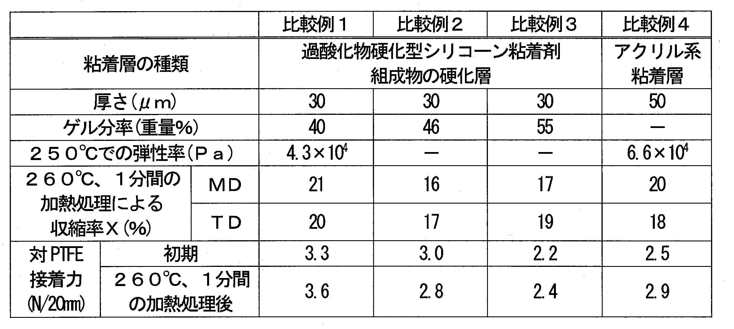
- Comparative Example 1 Except for using a peroxide-curable silicone pressure-sensitive adhesive composition (manufactured by Toray Dow Corning, SH4280 (1.2 parts by weight of peroxide)) instead of the addition reaction-curable silicone pressure-sensitive adhesive composition A. Obtained Sample A (strip shape) and Sample B (square) of Comparative Example 1 in the same manner as in Example 1. However, the curing conditions of the coating film were 200 ° C. and 3 minutes.
- Comparative Example 2 Except for using a peroxide-curable silicone pressure-sensitive adhesive composition (manufactured by Toray Dow Corning, SH4280 (2.4 parts by weight of peroxide compounding amount)) instead of the addition reaction-curable silicone pressure-sensitive adhesive composition A. Obtained Sample A (strip shape) and Sample B (square) of Comparative Example 2 in the same manner as in Example 1. However, the curing conditions of the coating film were 200 ° C. and 3 minutes.
- Comparative Example 3 instead of the addition reaction curable silicone pressure-sensitive adhesive composition A, a peroxide-curable silicone pressure-sensitive adhesive composition (manufactured by Shin-Etsu Chemical Co., Ltd., KR101-10 (peroxide compounding amount: 2.4 parts by weight)) was used. Sample A (strip shape) and sample B (square) of Comparative Example 3 were obtained in the same manner as in Example 1 except for the above. However, the curing conditions of the coating film were 200 ° C. and 3 minutes.
- Comparative Example 4 Sample A (belt-shaped) of Comparative Example 4 in the same manner as in Example 1 except that an acrylic pressure-sensitive adhesive composition (Nitto Denko, No. 5919) was used instead of the addition reaction-curable silicone pressure-sensitive adhesive composition A. ) And sample B (square) were obtained. However, instead of curing after coating, the coating film was dried by heating at 120 ° C. for 3 minutes. Further, the pressure-sensitive adhesive composition was applied so that the thickness after drying was 50 ⁇ m.
- an acrylic pressure-sensitive adhesive composition Nito Denko, No. 5919
- FIG. 8 shows the appearance of Sample B of each Example and Comparative Example after the heat treatment (260 ° C., 1 minute) carried out in the evaluation of the shrinkage rate X.
- the shrinkage of the cured adhesive layer due to the heat treatment was suppressed in the examples as compared with the comparative examples. Further, in Examples 1 to 3 in which the gel fraction is in the range of 25 to 65% by weight, the adhesive force to PTFE is improved as compared with Example 4 in which the gel fraction is outside the above range, and after the heat treatment. The adhesive strength was improved over the initial adhesive strength. As shown in FIG. 8, in Comparative Example 1, peeling 61 of the cured adhesive layer from the polyimide base material occurred. The peeling 61 proceeded from the outer circumference of the sample B to the portion indicated by reference numeral 62.
- the protective cover member of the present invention can be used, for example, for manufacturing a semiconductor element such as MEMS and / or a circuit board including the element.
Landscapes
- Chemical & Material Sciences (AREA)
- Organic Chemistry (AREA)
- Engineering & Computer Science (AREA)
- Microelectronics & Electronic Packaging (AREA)
- Chemical Kinetics & Catalysis (AREA)
- Computer Hardware Design (AREA)
- Adhesive Tapes (AREA)
- Laminated Bodies (AREA)
- Adhesives Or Adhesive Processes (AREA)
Abstract
Description
開口を有する面を持つ対象物の前記面に配置される保護カバー部材であって、
前記部材が前記面に配置されたときに前記開口を覆う形状を有する保護膜と、粘着剤層と、を含む積層体から構成され、
前記粘着剤層は、付加反応硬化型シリコーン粘着剤を含むシリコーン粘着剤組成物の硬化粘着層を備える、保護カバー部材、
を提供する。
基材シートと、前記基材シート上に配置された1又は2以上の保護カバー部材と、を備え、
前記保護カバー部材は、上記本発明の保護カバー部材である部材供給用シート、
を提供する。
本発明の保護カバー部材の一例を図1A及び図1Bに示す。図1Bは、図1Aの保護カバー部材1を粘着剤層3の側から見た平面図である。図1Aには、図1Bの断面A-Aが示されている。保護カバー部材1は、開口を有する面を持つ対象物の当該面(配置面)に配置される部材である。配置面への保護カバー部材1の配置により、例えば、上記開口への及び/又は上記開口からの異物の侵入、換言すれば、上記開口を介した異物の侵入、を防ぎうる。保護カバー部材1は、開口を有する面を持つ対象物の当該面に配置されて、上記開口への異物の侵入を防ぐ部材であってもよい。保護カバー部材1は、保護膜2と粘着剤層3とを含む積層体4から構成される。保護膜2は、保護カバー部材1が上記面に配置されたときに上記開口を覆う形状を有する。粘着剤層3は、保護膜2の一方の主面の側に位置している。粘着剤層3は、保護膜2と接合している。保護カバー部材1は、粘着剤層3により、対象物の配置面に固定できる。
本発明の部材供給用シートの一例を図7に示す。図7の部材供給用シート21は、基材シート22と、基材シート22上に配置された複数の保護カバー部材1とを備える。部材供給用シート21は、保護カバー部材1を供給するためのシートである。部材供給用シート21によれば、例えば、対象物の面に配置する工程に対して、保護カバー部材1を効率的に供給できる。
硬化粘着層のゲル分率は、上述の方法により求めた。測定環境の温度は25℃、湿度は50%RHとした。
硬化粘着層の貯蔵弾性率(250℃)は、上述の方法により求めた。レオメーターには、Rheometric Scientific製、Advanced Rheometric Expansion System (ARES)を使用した。測定サンプルは円形とし、面方向の面積は78.5mm2、厚さは5mmとした。
硬化粘着層の260℃での収縮率Xは、以下のようにして求めた。各実施例及び比較例において作製したサンプルB(硬化粘着層/ポリイミド基材(厚さ25μm)/硬化粘着層の3層構造を有する一辺が1.7mmの正方形)に対して、260℃に保持した加熱槽に1分間保持する加熱処理を実施した。処理後、サンプルを放冷して25℃とし、硬化粘着層のMD及びTDの双方の方向について、それぞれ、硬化粘着層の最短の寸法Dminを測定した。ポリイミド基材を挟持する2つの硬化粘着層の各々に対して求めた最短の寸法Dminの平均値を、加熱処理後の各方向の寸法D1とした。求めたD1から、式:収縮率X=(1.7-D1)/1.7×100(%)により、収縮率X(%)を算出した。最短の寸法Dminは、光学顕微鏡による拡大観察像(倍率47倍)の画像解析により求めた。最短の寸法Dminの測定は、温度25℃及び湿度50%RHで実施した。
PTFE膜に対する硬化粘着層の初期接着力及び加熱処理(260℃、1分間)後の接着力は、180°引きはがし試験により、以下のように求めた。
付加反応硬化型シリコーン粘着剤組成物Aとして、100重量部の信越化学工業製KR3700と、0.05重量部の白金触媒(信越化学製、CAT-PL-50T)との混合物(組成物a)を準備した。KR3700は、主たる成分Aとしてジメチルポリシロキサン、主たる成分BとしてMQレジン、主たる成分Cとしてハイドロジェンジメチルポリシロキサンを含む。また、KR3700は、過酸化物硬化型シリコーン粘着剤を含まない。
付加反応硬化型シリコーン粘着剤組成物Aとして、100重量部の信越化学工業製X-40-3240と、0.05重量部の白金触媒(信越化学製、CAT-PL-50T)との混合物を使用した以外は実施例1と同様にして、実施例2のサンプルA(帯状)及びサンプルB(正方形)を得た。X-40-3240は、主たる成分Aとしてジメチルポリシロキサン、主たる成分BとしてMQレジン、主たる成分Cとしてハイドロジェンジメチルポリシロキサンを含む。また、X-40-3240は、過酸化物硬化型シリコーン粘着剤を含まない。
付加反応硬化型シリコーン粘着剤組成物Aとして、75重量部の信越化学工業製KR3700と、25重量部の信越化学工業製KR3704と、0.05重量部の白金触媒(信越化学製、CAT-PL-50T)との混合物を使用した以外は実施例1と同様にして、実施例3のサンプルA(帯状)及びサンプルB(正方形)を得た。KR3704は、主たる成分Aとしてジメチルポリシロキサン、主たる成分BとしてMQレジン、主たる成分Cとしてハイドロジェンジメチルポリシロキサンを含む。また、KR3704は、過酸化物硬化型シリコーン粘着剤を含まない。
付加反応硬化型シリコーン粘着剤組成物Aとして、25重量部の信越化学工業製KR3700と、75重量部の信越化学工業製KR3704と、0.05重量部の白金触媒(信越化学製、CAT-PL-50T)との混合物を使用した以外は実施例1と同様にして、実施例4のサンプルA(帯状)及びサンプルB(正方形)を得た。
付加反応硬化型シリコーン粘着剤組成物Aの代わりに、過酸化物硬化型シリコーン粘着剤組成物(東レ・ダウコーニング製、SH4280(過酸化物の配合量1.2重量部))を使用した以外は実施例1と同様にして、比較例1のサンプルA(帯状)及びサンプルB(正方形)を得た。ただし、塗布膜の硬化条件は、200℃及び3分とした。
付加反応硬化型シリコーン粘着剤組成物Aの代わりに、過酸化物硬化型シリコーン粘着剤組成物(東レ・ダウコーニング製、SH4280(過酸化物の配合量2.4重量部))を使用した以外は実施例1と同様にして、比較例2のサンプルA(帯状)及びサンプルB(正方形)を得た。ただし、塗布膜の硬化条件は、200℃及び3分とした。
付加反応硬化型シリコーン粘着剤組成物Aの代わりに、過酸化物硬化型シリコーン粘着剤組成物(信越化学工業製、KR101-10(過酸化物の配合量2.4重量部))を使用した以外は実施例1と同様にして、比較例3のサンプルA(帯状)及びサンプルB(正方形)を得た。ただし、塗布膜の硬化条件は、200℃及び3分とした。
付加反応硬化型シリコーン粘着剤組成物Aの代わりに、アクリル系粘着剤組成物(日東電工製、No.5919)を使用した以外は実施例1と同様にして、比較例4のサンプルA(帯状)及びサンプルB(正方形)を得た。ただし、塗布後の硬化の代わりに、120℃、3分の加熱による塗布膜の乾燥を実施した。また、粘着剤組成物の塗布は、乾燥後の厚さが50μmとなるように実施した。

Claims (16)
- 開口を有する面を持つ対象物の前記面に配置される保護カバー部材であって、
前記部材が前記面に配置されたときに前記開口を覆う形状を有する保護膜と、粘着剤層と、を含む積層体から構成され、
前記粘着剤層は、付加反応硬化型シリコーン粘着剤を含むシリコーン粘着剤組成物の硬化粘着層を備える、保護カバー部材。 - 前記シリコーン粘着剤組成物は、前記付加反応硬化型シリコーン粘着剤を主成分として含む、請求項1に記載の保護カバー部材。
- 前記シリコーン粘着剤組成物は、過酸化物硬化型シリコーン粘着剤を含まない、請求項1に記載の保護カバー部材。
- 前記硬化粘着層のゲル分率が25~65重量%である、請求項1~3のいずれかに記載の保護カバー部材。
- 前記粘着剤層及び/又は前記硬化粘着層が前記保護膜と接している、請求項1~4のいずれかに記載の保護カバー部材。
- 前記粘着剤層及び/又は前記硬化粘着層が、前記対象物の前記面との接合面となる、請求項1~5のいずれかに記載の保護カバー部材。
- 前記積層体は、前記保護膜の一方の主面の側に位置する第1の前記粘着剤層と、前記保護膜の他方の主面の側に位置する第2の前記粘着剤層と、含む、請求項1~6のいずれかに記載の保護カバー部材。
- 前記粘着剤層は、基材と、前記基材の少なくとも一方の面に配置された前記硬化粘着層と、を含む粘着テープを備える、請求項1~7のいずれかに記載の保護カバー部材。
- 前記粘着テープが両面粘着テープである、請求項8に記載の保護カバー部材。
- 前記基材が耐熱性樹脂を含む、請求項8に記載の保護カバー部材。
- 前記保護膜は厚さ方向の通気性を有する、請求項1~10のいずれかに記載の保護カバー部材。
- 前記保護膜はポリテトラフルオロエチレン膜を含む、請求項1~11のいずれかに記載の保護カバー部材。
- 前記保護膜の面積が175mm2以下である請求項1~12のいずれかに記載の保護カバー部材。
- 前記保護膜の主面に垂直に見て、
前記粘着剤層は、前記保護膜の周縁部に配置されており、
前記保護膜の中心から前記保護膜の外周に至る線分のうち最短の前記線分の長さL1に対する、前記最短の線分における前記粘着剤層と重複する部分の長さL2の比L2/L1が0.3以下である、請求項1~13のいずれかに記載の保護カバー部材。 - 微小電気機械システム(MEMS)用である、請求項1~14のいずれかに記載の保護カバー部材。
- 基材シートと、前記基材シート上に配置された1又は2以上の保護カバー部材と、を備え、
前記保護カバー部材は、請求項1~15のいずれかに記載の保護カバー部材である部材供給用シート。
Priority Applications (4)
| Application Number | Priority Date | Filing Date | Title |
|---|---|---|---|
| CN202180021586.8A CN115279855B (zh) | 2020-03-18 | 2021-03-11 | 保护罩构件及构件供给用片 |
| JP2022508296A JP7774554B2 (ja) | 2020-03-18 | 2021-03-11 | 保護カバー部材及び部材供給用シート |
| US17/910,229 US20230108896A1 (en) | 2020-03-18 | 2021-03-11 | Protective cover member and member supplying sheet |
| DE112021001702.0T DE112021001702T5 (de) | 2020-03-18 | 2021-03-11 | Schutzabdeckungselement und elementzuführungslage |
Applications Claiming Priority (4)
| Application Number | Priority Date | Filing Date | Title |
|---|---|---|---|
| JP2020047325 | 2020-03-18 | ||
| JP2020-047325 | 2020-03-18 | ||
| JP2020-119319 | 2020-07-10 | ||
| JP2020119319 | 2020-07-10 |
Publications (1)
| Publication Number | Publication Date |
|---|---|
| WO2021187328A1 true WO2021187328A1 (ja) | 2021-09-23 |
Family
ID=77772032
Family Applications (1)
| Application Number | Title | Priority Date | Filing Date |
|---|---|---|---|
| PCT/JP2021/009881 Ceased WO2021187328A1 (ja) | 2020-03-18 | 2021-03-11 | 保護カバー部材及び部材供給用シート |
Country Status (6)
| Country | Link |
|---|---|
| US (1) | US20230108896A1 (ja) |
| JP (1) | JP7774554B2 (ja) |
| CN (1) | CN115279855B (ja) |
| DE (1) | DE112021001702T5 (ja) |
| TW (1) | TW202140736A (ja) |
| WO (1) | WO2021187328A1 (ja) |
Families Citing this family (1)
| Publication number | Priority date | Publication date | Assignee | Title |
|---|---|---|---|---|
| CN114929825B (zh) * | 2020-08-07 | 2024-03-19 | 日东电工株式会社 | 保护罩构件及构件供给用片 |
Citations (5)
| Publication number | Priority date | Publication date | Assignee | Title |
|---|---|---|---|---|
| JP2007081881A (ja) * | 2005-09-14 | 2007-03-29 | Nitto Denko Corp | 通音膜、通音膜付き電子部品及びその電子部品を実装した回路基板の製造方法 |
| JP2010000464A (ja) * | 2008-06-20 | 2010-01-07 | Japan Gore Tex Inc | 通気フィルター及びその製造方法 |
| JP2012253481A (ja) * | 2011-06-01 | 2012-12-20 | Nitto Denko Corp | 防水通音部材 |
| WO2019089021A1 (en) * | 2017-11-01 | 2019-05-09 | W. L. Gore & Associates, Inc. | Protective cover assembly having improved z-strength |
| JP2019122890A (ja) * | 2018-01-12 | 2019-07-25 | 信越化学工業株式会社 | 粘着層付き通気フィルタ |
Family Cites Families (2)
| Publication number | Priority date | Publication date | Assignee | Title |
|---|---|---|---|---|
| JP2012144701A (ja) * | 2010-12-25 | 2012-08-02 | Nitto Denko Corp | 粘着テープ、粘着テープで被覆された平角電線、およびそれを用いた電気機器 |
| KR102232802B1 (ko) * | 2015-12-10 | 2021-03-25 | 가부시키가이샤 데라오카 세이사쿠쇼 | 점착제 조성물 및 점착 테이프 |
-
2021
- 2021-03-11 DE DE112021001702.0T patent/DE112021001702T5/de active Pending
- 2021-03-11 WO PCT/JP2021/009881 patent/WO2021187328A1/ja not_active Ceased
- 2021-03-11 JP JP2022508296A patent/JP7774554B2/ja active Active
- 2021-03-11 CN CN202180021586.8A patent/CN115279855B/zh active Active
- 2021-03-11 US US17/910,229 patent/US20230108896A1/en active Pending
- 2021-03-15 TW TW110109081A patent/TW202140736A/zh unknown
Patent Citations (5)
| Publication number | Priority date | Publication date | Assignee | Title |
|---|---|---|---|---|
| JP2007081881A (ja) * | 2005-09-14 | 2007-03-29 | Nitto Denko Corp | 通音膜、通音膜付き電子部品及びその電子部品を実装した回路基板の製造方法 |
| JP2010000464A (ja) * | 2008-06-20 | 2010-01-07 | Japan Gore Tex Inc | 通気フィルター及びその製造方法 |
| JP2012253481A (ja) * | 2011-06-01 | 2012-12-20 | Nitto Denko Corp | 防水通音部材 |
| WO2019089021A1 (en) * | 2017-11-01 | 2019-05-09 | W. L. Gore & Associates, Inc. | Protective cover assembly having improved z-strength |
| JP2019122890A (ja) * | 2018-01-12 | 2019-07-25 | 信越化学工業株式会社 | 粘着層付き通気フィルタ |
Also Published As
| Publication number | Publication date |
|---|---|
| JPWO2021187328A1 (ja) | 2021-09-23 |
| DE112021001702T5 (de) | 2023-02-23 |
| CN115279855A (zh) | 2022-11-01 |
| JP7774554B2 (ja) | 2025-11-21 |
| CN115279855B (zh) | 2025-02-21 |
| TW202140736A (zh) | 2021-11-01 |
| US20230108896A1 (en) | 2023-04-06 |
Similar Documents
| Publication | Publication Date | Title |
|---|---|---|
| CN102099187B (zh) | 通气滤膜及其制造方法 | |
| JP7461301B2 (ja) | 通気性粘着シート及び通気性製品 | |
| WO2022210435A1 (ja) | 部材供給用シート | |
| JP6488044B2 (ja) | 積層体および巻回体 | |
| KR102912889B1 (ko) | 보호 커버 부재 및 이것을 구비하는 부재 공급용 시트 | |
| WO2021187328A1 (ja) | 保護カバー部材及び部材供給用シート | |
| JP7829103B2 (ja) | 多孔質膜、フィルター部材及び部材供給アセンブリ | |
| US12120832B2 (en) | Air-permeable member with removable protective film for covering ventilation hole | |
| US20240286389A1 (en) | Protective cover member, sheet for member supply, and microelectromechanical system | |
| JP6522039B2 (ja) | 保護フィルム付膜片、保護フィルム付膜片の保護フィルム除去方法および電気装置の製造方法 | |
| JP2018176747A (ja) | 積層体および巻回体 | |
| WO2022009965A1 (ja) | シリコーン系粘着剤及び粘着テープ | |
| TW202200369A (zh) | 構件供給用片材 | |
| WO2025249337A1 (ja) | 多孔質フィルム、通気部材及び部材供給用シート | |
| WO2025205696A1 (ja) | 多孔質フィルム、通気部材及び部材供給用シート | |
| WO2025205693A1 (ja) | 多孔質フィルム、通気部材及び部材供給用シート |
Legal Events
| Date | Code | Title | Description |
|---|---|---|---|
| 121 | Ep: the epo has been informed by wipo that ep was designated in this application |
Ref document number: 21771426 Country of ref document: EP Kind code of ref document: A1 |
|
| ENP | Entry into the national phase |
Ref document number: 2022508296 Country of ref document: JP Kind code of ref document: A |
|
| 122 | Ep: pct application non-entry in european phase |
Ref document number: 21771426 Country of ref document: EP Kind code of ref document: A1 |
|
| WWG | Wipo information: grant in national office |
Ref document number: 202180021586.8 Country of ref document: CN |