WO2021186983A1 - 流体回路及び血圧測定装置 - Google Patents
流体回路及び血圧測定装置 Download PDFInfo
- Publication number
- WO2021186983A1 WO2021186983A1 PCT/JP2021/005505 JP2021005505W WO2021186983A1 WO 2021186983 A1 WO2021186983 A1 WO 2021186983A1 JP 2021005505 W JP2021005505 W JP 2021005505W WO 2021186983 A1 WO2021186983 A1 WO 2021186983A1
- Authority
- WO
- WIPO (PCT)
- Prior art keywords
- cuff
- valve
- fluid
- blood pressure
- pressure
- Prior art date
- Legal status (The legal status is an assumption and is not a legal conclusion. Google has not performed a legal analysis and makes no representation as to the accuracy of the status listed.)
- Ceased
Links
Images





Classifications
-
- A—HUMAN NECESSITIES
- A61—MEDICAL OR VETERINARY SCIENCE; HYGIENE
- A61B—DIAGNOSIS; SURGERY; IDENTIFICATION
- A61B5/00—Measuring for diagnostic purposes; Identification of persons
- A61B5/02—Detecting, measuring or recording for evaluating the cardiovascular system, e.g. pulse, heart rate, blood pressure or blood flow
- A61B5/021—Measuring pressure in heart or blood vessels
- A61B5/022—Measuring pressure in heart or blood vessels by applying pressure to close blood vessels, e.g. against the skin; Ophthalmodynamometers
- A61B5/02233—Occluders specially adapted therefor
-
- A—HUMAN NECESSITIES
- A61—MEDICAL OR VETERINARY SCIENCE; HYGIENE
- A61B—DIAGNOSIS; SURGERY; IDENTIFICATION
- A61B5/00—Measuring for diagnostic purposes; Identification of persons
- A61B5/02—Detecting, measuring or recording for evaluating the cardiovascular system, e.g. pulse, heart rate, blood pressure or blood flow
- A61B5/021—Measuring pressure in heart or blood vessels
- A61B5/022—Measuring pressure in heart or blood vessels by applying pressure to close blood vessels, e.g. against the skin; Ophthalmodynamometers
- A61B5/0235—Valves specially adapted therefor
-
- A—HUMAN NECESSITIES
- A61—MEDICAL OR VETERINARY SCIENCE; HYGIENE
- A61B—DIAGNOSIS; SURGERY; IDENTIFICATION
- A61B5/00—Measuring for diagnostic purposes; Identification of persons
- A61B5/02—Detecting, measuring or recording for evaluating the cardiovascular system, e.g. pulse, heart rate, blood pressure or blood flow
- A61B5/021—Measuring pressure in heart or blood vessels
- A61B5/022—Measuring pressure in heart or blood vessels by applying pressure to close blood vessels, e.g. against the skin; Ophthalmodynamometers
- A61B5/0225—Measuring pressure in heart or blood vessels by applying pressure to close blood vessels, e.g. against the skin; Ophthalmodynamometers the pressure being controlled by electric signals, e.g. derived from Korotkoff sounds
-
- G—PHYSICS
- G05—CONTROLLING; REGULATING
- G05D—SYSTEMS FOR CONTROLLING OR REGULATING NON-ELECTRIC VARIABLES
- G05D16/00—Control of fluid pressure
- G05D16/028—Controlling a pressure difference
-
- G—PHYSICS
- G05—CONTROLLING; REGULATING
- G05D—SYSTEMS FOR CONTROLLING OR REGULATING NON-ELECTRIC VARIABLES
- G05D16/00—Control of fluid pressure
- G05D16/20—Control of fluid pressure characterised by the use of electric means
- G05D16/2006—Control of fluid pressure characterised by the use of electric means with direct action of electric energy on controlling means
- G05D16/208—Control of fluid pressure characterised by the use of electric means with direct action of electric energy on controlling means using a combination of controlling means as defined in G05D16/2013 and G05D16/2066
-
- A—HUMAN NECESSITIES
- A61—MEDICAL OR VETERINARY SCIENCE; HYGIENE
- A61B—DIAGNOSIS; SURGERY; IDENTIFICATION
- A61B5/00—Measuring for diagnostic purposes; Identification of persons
- A61B5/68—Arrangements of detecting, measuring or recording means, e.g. sensors, in relation to patient
- A61B5/6801—Arrangements of detecting, measuring or recording means, e.g. sensors, in relation to patient specially adapted to be attached to or worn on the body surface
- A61B5/6802—Sensor mounted on worn items
- A61B5/681—Wristwatch-type devices
Definitions
- the present invention relates to a fluid circuit and a blood pressure measuring device used for blood pressure measurement.
- blood pressure measuring devices used for measuring blood pressure have been used as a means for checking the health condition not only in medical facilities but also at home.
- the blood pressure measuring device for example, expands and contracts a cuff wrapped around the upper arm or wrist of a living body, detects the pressure of the cuff with a pressure sensor, and detects the vibration of the arterial wall to measure the blood pressure.
- Such a blood pressure measuring device is known to have a technique including a sensing cuff for measuring blood pressure and a plurality of cuffs including a pressing cuff for pressing the sensing cuff toward a living body.
- the blood pressure measuring device has a pump, and the cuff is inflated by supplying a fluid such as air to the cuff by the pump.
- Japanese Patent Application Laid-Open No. 2009-22477 discloses a technique as such a blood pressure measuring device, which includes a fluid circuit in which an orifice is arranged as a fluid resistance between a pressing cuff and a sensing cuff to reduce an air injection amount. ing.
- the flow rate changes in proportion to the pressure difference between the pressing cuff on the primary side of the orifice and the sensing cuff on the secondary side.
- the flow rate of air supplied from the pump changes in proportion to the pressure difference between the pressing cuff on the primary side of the orifice and the sensing cuff on the secondary side of the orifice. Therefore, if the pressurizing time of the living body at the time of blood pressure measurement changes, the amount of air flowing into the sensing cuff changes, and an error occurs in the amount of air injected into the sensing cuff.
- the configuration includes three or more cuffs, if a fluid resistance such as an orifice is provided between the primary side cuff and the secondary side cuff, the amount of air flowing into the secondary side cuff will increase. Change.
- the pressurization time of the living body at the time of blood pressure measurement changes depending on the thickness of the measurement site of the subject, the wrapping state of the arm band, the pump characteristics, and the like.
- the air injection amount supplied to the sensing cuff needs to be smaller than the intake injection amount supplied to the pressing cuff. Therefore, it is necessary to use an orifice having a large fluid resistance for the orifice provided between the pressing cuff and the sensing cuff. Such an orifice requires a minute pinhole, and requires an expensive and highly accurate processing technique.
- an object of the present invention is to provide a fluid circuit and a blood pressure measuring device capable of constantly controlling the amount of air injected into the cuff.
- a first cuff connected to the secondary side of a pump that supplies fluid to the secondary side, a second cuff connected to the secondary side of the first cuff, the first cuff and Between the first valve, which is provided between the second cuffs and closes when the differential pressure between the first cuff and the second cuff reaches a predetermined differential pressure, and between the first valve and the second cuff. Therefore, a fluid circuit including a fluid resistor provided on the secondary side of the first valve is provided.
- the fluid includes liquid and air.
- a cuff includes a sac-like structure that is wrapped around the upper arm or wrist of a living body when measuring blood pressure and expands when a fluid is supplied.
- an air bag that expands with air.
- the fluid supplied to the secondary side by the pump is supplied to the first cuff and is supplied to the first cuff because it passes through the fluid resistance and is supplied to the second cuff.
- the flow rate supplied to the second cuff is smaller than the flow rate of air. Therefore, the pressure of the first cuff is higher than the pressure of the second cuff.
- the first valve closes, so that the supply of the fluid to the second cuff is stopped. Therefore, the fluid circuit can keep the amount of fluid injected into the second cuff constant.
- the fluid circuit is set so that the first valve is closed by the differential pressure between the first cuff and the second cuff when the second cuff reaches the desired pressure, so that the pressure of the second cuff becomes the desired pressure.
- a supply amount of fluid can be supplied to the second cuff.
- a fluid circuit according to the above aspect comprising a second valve provided in parallel with the first valve and the fluid resistance and opened when the pressure of the first cuff is lower than the pressure of the second cuff. Is provided.
- the second valve opens. Therefore, when the pressure of the first cuff is higher than the pressure of the second cuff, the fluid of the first cuff is preferentially discharged, and the fluid of the second cuff is discharged through the fluid resistance. Further, when the pressure of the first cuff is lower than the pressure of the second cuff, the second valve is opened and the discharge rate of the fluid of the second cuff is increased.
- a pump that supplies fluid to the secondary side, a fluid circuit of the above aspect, an on-off valve provided between the pump and the first cuff that opens and closes a flow path to the atmosphere.
- a blood pressure measuring device including a pressure sensor connected to the second cuff and a control unit that controls the pump and the on-off valve based on the pressure detected by the pressure sensor is provided.
- the blood pressure measuring device can drive the pump based on the pressure of the second cuff, the fluid can be supplied to the second cuff at least until the second cuff has a suitable pressure. Further, when the blood pressure measuring device discharges the fluids of the first cuff and the second cuff, the blood pressure measuring device can discharge the fluid from the first cuff and the second cuff by controlling and opening the on-off valve by the control unit. can.
- the blood pressure measuring device of the above aspect includes the pump, the on-off valve, the pressure sensor, and the main body of the device accommodating the control unit, and the first valve and the fluid resistance are integrated with the first cuff.
- a blood pressure measuring device provided can be provided.
- a control unit and a pump, an on-off valve, and a pressure sensor controlled by the control unit are housed in the device body.
- the first valve and the fluid resistance which are used for fluid control of the fluid circuit and are not electrically connected to the control unit, are integrally provided in the first cuff, and the first valve and the fluid resistance are not housed in the apparatus main body. Therefore, the blood pressure measuring device can be miniaturized.
- a first cuff connected to the secondary side of a pump that supplies fluid to the secondary side and a second connected cuff branched between the pump and the first cuff. And, which is branched between the pump and the first cuff, is provided on the primary side of the second cuff, and closes when the differential pressure between the first cuff and the second cuff reaches a predetermined differential pressure.
- a fluid circuit comprising a switching valve to be provided and a fluid resistance provided between the switching valve and the second cuff is provided.
- the fluid supplied to the secondary side by the pump is supplied to the first cuff and is supplied to the second cuff through the fluid resistor when the switching valve is open.
- the flow rate supplied to the second cuff is smaller than the flow rate of the air supplied to the first cuff. Therefore, the pressure of the first cuff is higher than the pressure of the second cuff.
- the switching valve is closed, so that the supply of the fluid to the second cuff is stopped. Therefore, in the fluid circuit, the amount of fluid supplied to the second cuff becomes constant when the switching valve is closed.
- the second valve opens.
- the pressure of the first cuff is higher than the pressure of the second cuff
- the fluid of the first cuff is preferentially discharged, and the fluid of the second cuff is discharged through the fluid resistance.
- the second valve is opened and the discharge rate of the fluid of the second cuff is increased.
- a blood pressure measuring device including an on-off valve, a pressure sensor connected to the second cuff, and a control unit for controlling the pump, the switching valve, and the on-off valve based on the pressure detected by the pressure sensor.
- the blood pressure measuring device can drive the pump based on the pressure of the second cuff, the fluid can be supplied to the second cuff at least until the second cuff has a suitable pressure. Further, when the blood pressure measuring device discharges the fluids of the first cuff and the second cuff, the blood pressure measuring device can discharge the fluid from the first cuff and the second cuff by controlling and opening the on-off valve by the control unit. can.
- the blood pressure measuring device of the above aspect comprising the device main body including the pump, the on-off valve, the switching valve, the pressure sensor, and the control unit, the first valve and the fluid resistance are the first.
- a blood pressure measuring device provided integrally with the cuff is provided.
- control unit and the pump, on-off valve, and pressure sensor controlled by the control unit are housed in the main body of the device.
- the first valve and the fluid resistance which are used for fluid control of the fluid circuit and are not electrically connected to the control unit, are integrally provided in the first cuff, and the first valve and the fluid resistance are not housed in the apparatus main body. Therefore, the blood pressure measuring device can be miniaturized.
- the present invention can provide a fluid circuit and a blood pressure measuring device capable of constantly controlling the amount of air injected into the cuff.
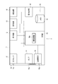
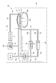
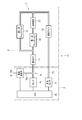
- FIG. 1 is an explanatory diagram schematically showing a configuration of a blood pressure measuring device according to the first embodiment of the present invention.
- FIG. 2 is a block diagram schematically showing the configuration of the main body of the blood pressure measuring device.
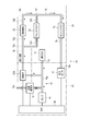
- FIG. 3 is a block diagram showing a configuration of the blood pressure measuring device and an example of its use.
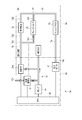
- FIG. 4 is a block diagram showing a configuration of the blood pressure measuring device and an example of its use.
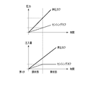
- FIG. 5 is an explanatory diagram showing an example of a change in pressure and a change in injection amount in blood pressure measurement of the same blood pressure measuring device.
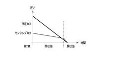
- FIG. 6 is an explanatory diagram showing an example of a change in pressure at the time of exhaust after measuring the blood pressure of the blood pressure measuring device.
- FIG. 1 is an explanatory diagram schematically showing a configuration of a blood pressure measuring device according to the first embodiment of the present invention.
- FIG. 2 is a block diagram schematically showing the configuration of the main body of the blood pressure measuring device.
- FIG. 3 is
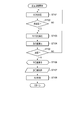
- FIG. 7 is a flow chart showing an example of using the blood pressure measuring device.
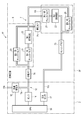
- FIG. 8 is an explanatory diagram schematically showing the configuration of the blood pressure measuring device according to the second embodiment of the present invention.
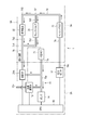
- FIG. 9 is a block diagram showing a configuration of the blood pressure measuring device and an example of its use.
- FIG. 10 is a block diagram showing a configuration of the blood pressure measuring device and an example of its use.
- FIG. 11 is a block diagram showing a configuration of the blood pressure measuring device and an example of its use.
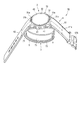
- FIG. 12 is a perspective view showing the configuration of the blood pressure measuring device according to the third embodiment of the present invention.
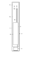
- FIG. 13 is a plan view showing the configuration of the cuff structure and the fluid control unit of the blood pressure measuring device.
- FIG. 14 is an explanatory diagram schematically showing the configuration of the blood pressure measuring device according to the fourth embodiment of the present invention.
- FIG. 15 is an explanatory diagram schematically showing the configuration of the blood pressure measuring device according to the fifth embodiment of the present invention.
- FIG. 16 is an explanatory diagram schematically showing the configuration of the blood pressure measuring device according to the sixth embodiment of the present invention.
- FIG. 17 is an explanatory diagram schematically showing the configuration of the blood pressure measuring device according to the eighth embodiment of the present invention.
- FIG. 18 is an explanatory diagram schematically showing the configuration of the blood pressure measuring device according to the ninth embodiment of the present invention.
- FIG. 19 is an explanatory diagram schematically showing the configuration of the blood pressure measuring device according to the tenth embodiment of the present invention.
- FIG. 1 is an explanatory diagram schematically showing the configuration of the blood pressure measuring device 1 according to the first embodiment of the present invention.
- FIG. 2 is a block diagram schematically showing the configuration of the device main body 2 of the blood pressure measuring device 1.
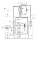
- FIG. 3 is a block diagram showing the configuration of the blood pressure measuring device 1 and showing an example of the flow of the fluid supplied to the cuffs 71 and 73 in the blood pressure measurement.
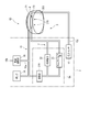
- FIG. 4 is a block diagram showing the configuration of the blood pressure measuring device 1 and showing an example of the flow of the fluid in the discharge of the fluid after the blood pressure measurement.
- FIG. 1 is an explanatory diagram schematically showing the configuration of the blood pressure measuring device 1 according to the first embodiment of the present invention.
- FIG. 2 is a block diagram schematically showing the configuration of the device main body 2 of the blood pressure measuring device 1.
- FIG. 3 is a block diagram showing the configuration of the blood pressure measuring device 1 and showing an example of the flow of the fluid supplied to the cuffs 71 and 73 in the
- FIG. 5 is an explanatory diagram showing an example of a change in pressure and a change in injection amount of each of the cuffs 71 and 73 in the blood pressure measurement of the blood pressure measuring device 1.
- FIG. 6 is an explanatory diagram showing an example of a change in pressure of the cuffs 71 and 73 in the discharge of the fluid after the blood pressure measurement of the blood pressure measuring device 1.
- the blood pressure measuring device 1 is an electronic blood pressure measuring device worn on a living body.
- the blood pressure measuring device 1 is, for example, an electronic blood pressure measuring device that is attached to a living body 200 such as a wrist and has an aspect of measuring blood pressure from an artery 210 of the living body 200.
- the blood pressure measuring device 1 includes a device main body 2 and a fluid circuit 3.
- the blood pressure measuring device 1 includes at least a fixture 4 such as a belt that fixes the fluid circuit 3 to the living body 200.
- the living body 200 in FIG. 1 shows a wrist, the living body 200 may be an upper arm or the like.
- the device main body 2 includes a case 11, a display device 12, an operating device 13, a pump 14, a flow path section 15, an on-off valve 16, a pressure sensor 17, and a power supply section 18.
- a communication device 19 and a control board 20 are provided.
- the case 11 houses, for example, a display device 12, an operating device 13, a pump 14, a flow path unit 15, an on-off valve 16, a pressure sensor 17, a power supply unit 18, a communication device 19, and a control board 20. Further, the case 11 is formed by exposing a part of the display device 12 so that a part of the display device 12 can be visually recognized from the outside, or by using a transparent material. The case 11 may be configured to accommodate a part of the configuration of the fluid circuit 3.
- the display device 12 is electrically connected to the control board 20.
- the display device 12 is, for example, a liquid crystal display (LCD: Liquid Crystal Display) or an organic electroluminescence display (OELD: Organic Electro Luminescence Display).
- the display device 12 displays various information including the date and time, the blood pressure value such as the systolic blood pressure and the diastolic blood pressure, and the measurement result such as the heart rate according to the control signal from the control board 20.
- the operation device 13 inputs a command from the user.
- the operation device 13 includes a plurality of buttons, a sensor that detects the operation of the buttons, a touch panel of a pressure-sensitive type or a capacitance type provided in the case 11, a display device 12, or the like, and a microphone that receives a command by sound. And so on.
- the operation device 13 is operated by the user to convert a command into an electric signal and output the electric signal to the control board 20.
- the pump 14 is, for example, a piezoelectric pump.
- the pump 14 compresses the fluid and supplies the compressed fluid to the fluid circuit 3 via the flow path portion 15.
- the pump 14 is electrically connected to the control board 20.
- the pump 14 is driven based on a control signal given from the control board 20.
- the fluid any gas or any liquid can be adopted.
- the fluid is air.
- the flow path portion 15 connects the pump 14, the on-off valve 16, and the pressure sensor 17 to the fluid circuit 3.
- the flow path portion 15 is any one of a tube, a pipe, a tank, a hollow portion and a groove formed in the case 11, or a combination thereof.
- the flow path portion 15 forms a flow path from the pump 14 to the secondary side, and a flow path that branches a part of the flow path from the pump 14 to the secondary side and connects to the on-off valve 16.
- Form 15a Further, the flow path portion 15 forms a flow path 15b that connects the on-off valve 16 to the atmosphere. Further, the flow path portion 15 forms a flow path 15c for connecting the pressure sensor 17 to the fluid circuit 3.
- the on-off valve 16 is electrically connected to the control board 20.
- the on-off valve 16 is controlled by the control board 20.
- the on-off valve 16 is opened and closed under the control of the control board 20.
- the on-off valve 16 is connected to the atmosphere by the flow path portion 15 and is switched to the open state to connect the pump 14 and the fluid circuit 3 to the atmosphere.
- the on-off valve 16 is an exhaust valve that opens the secondary side flow path of the pump 14 to the atmosphere. Further, for example, the on-off valve 16 is a rapid exhaust valve in which, for example, the opening degree of the on-off valve 16 or the opening area of the flow path portion 15 is set so that the fluid resistance is as low as possible, and rapid exhaust is possible. .. In each figure, the on-off valve 16 is shown as a quick exhaust valve 16. Such an on-off valve 16 is switched to a closed state when air is supplied to the fluid circuit 3 at the time of blood pressure measurement. Further, the on-off valve 16 is switched from the closed state to the open state by being controlled by the control board 20 when the fluid circuit 3 is exhausted. Further, the on-off valve 16 may be formed so that the opening degree can be adjusted.
- the pressure sensor 17 detects the pressure of the cuff arranged on the secondary side of the fluid circuit 3, and in the present embodiment, the pressure of the sensing cuff 73 described later of the fluid circuit 3.
- the pressure sensor 17 is fluidly connected to the sensing cuff 73 via the flow path portion 15 to detect the pressure in the sensing cuff 73.
- the pressure sensor 17 is electrically connected to the control board 20.
- the pressure sensor 17 outputs an electric signal corresponding to the detected pressure to the control board 20.
- the power supply unit 18 is a power source.
- the power supply unit is, for example, a secondary battery such as a lithium ion battery.
- the power supply unit 18 is electrically connected to the control board 20.
- the power supply unit 18 supplies power to the control board 20.
- the power supply unit 18 supplies electric power for driving to each configuration of the control board 20 and to the display device 12, the operation device 13, the pump 14, the on-off valve 16, the pressure sensor 17, and the communication device 19 via the control board 20. Supply.
- the communication device 19 is configured to be able to transmit and receive information wirelessly or by wire with an external device.
- the communication device 19 transmits, for example, information controlled by the control board 20 and information such as the measured blood pressure value and pulse to an external device, and also receives a software update program or the like from the external device. And send it to the control unit.
- the external device is, for example, an external terminal such as a smartphone, a tablet terminal, a personal computer, or a smart watch.
- the communication device 19 and the external device may be directly connected or may be connected via a network.
- the communication device 19 and an external device may be connected via a mobile communication network such as 4G or 5G or a wireless communication line such as Wimax or Wi-Fi (registered trademark).
- the communication device 19 and the external device may be connected by wireless communication means such as Bluetooth (registered trademark), NFC (Near Filed Communication), and infrared communication.
- the communication device 19 and the external device may be connected via a wired communication line such as a USB (Universal Serial Bus) or a LAN (Local Area Network) connection using a cable. Therefore, the communication device 19 may be configured to include a plurality of communication means such as a wireless antenna and a micro USB connector.
- the control board 20 includes, for example, a board 51, a storage unit 54, and a control unit 55.
- the control board 20 is configured by mounting the storage unit 54 and the control unit 55 on the board 51.
- the substrate 51 is fixed to the case 11.
- the storage unit 54 is a memory mounted on the board 51.
- the storage unit 54 includes a RAM (Random Access Memory), a ROM (Read Only Memory), and the like.
- the storage unit 54 stores various data.
- the storage unit 54 has program data for controlling the entire blood pressure measuring device 1, the pump 14, and the fluid circuit 3, setting data for setting various functions of the blood pressure measuring device 1, and pressure measured by the pressure sensor 17.
- the calculated data for calculating the blood pressure value and the pulse from the above can be changed and stored in advance.
- the storage unit 54 stores information such as the measured blood pressure value, the measured value such as the pulse, and the pressure value measured by the pressure sensor 17.
- the storage unit 54 can also store various data generated by the measurement processing unit 55a of the control unit 55.
- the control unit 55 includes a single or a plurality of processors mounted on the board 51.
- the processor is, for example, a CPU (Central Processing Unit).
- the control unit 55 controls the operation of the entire blood pressure measuring device 1 and the operations of the pump 14 and the fluid circuit 3 based on the program stored in the storage unit 54, and executes a predetermined operation (function). Further, the control unit 55 performs a predetermined calculation, analysis, processing, etc. in the control unit 55 according to the read program.
- the control unit 55 is electrically connected to the display device 12, the operating device 13, the pump 14, the on-off valve 16, and each pressure sensor 17, and supplies electric power. Further, the control unit 55 controls the operations of the display device 12, the pump 14, and the on-off valve 16 based on the electric signals output by the operating device 13 and the pressure sensor 17.
- control unit 55 includes a main CPU that controls the operation of the entire blood pressure measuring device 1 and a sub CPU that controls the operation of the fluid circuit 3.
- the control unit 55 may have a configuration in which all of the blood pressure measuring device 1 is performed by one CPU.
- the main CPU obtains a measurement result such as a blood pressure value such as systolic blood pressure and diastolic blood pressure and a heart rate from an electric signal output from the pressure sensor 17, and displays an image signal corresponding to the measurement result to the display device 12. Output.
- the sub CPU drives the pump 14 and the on-off valve 16 to send compressed air to the fluid circuit 3. Further, the sub CPU controls the drive and stop of the pump 14 and the opening and closing of the on-off valve 16 based on the electric signal output from the pressure sensor 17. By controlling the pump 14 and the on-off valve 16, the sub CPU supplies compressed air to the fluid circuit 3 and selectively depressurizes the fluid circuit 3.
- Such a control unit 55 configures a part or all of each function executed by the control unit 55 in terms of hardware by one or a plurality of integrated circuits or the like.
- the control unit 55 has a measurement processing unit 55a.
- the measurement processing unit 55a controls the pump 14 and the on-off valve 16 to supply air to the fluid circuit 3, and based on the pressure of the sensing cuff 73 described later in the fluid circuit 3 detected by the pressure sensor 17, the oshiro Blood pressure is calculated by the metric method.
- the fluid circuit 3 includes a cuff structure 6, a pipe group 7, and a fluid control unit 9.
- the fluid circuit 3 fluidly connects the cuff structure 6 and the fluid control unit 9 by the pipe group 7.
- the air flow is such that the pump 14 side (device body 2 side) is the primary side and the fluid circuit 3 side is the secondary side.
- the on-off valve 16 side (device main body 2 side) is the secondary side, and the fluid circuit 3 side is the primary side.
- the primary side and the secondary side are defined with reference to the air flow direction when air is supplied from the pump 14 to the cuff structure 6 and the pipe group 7. do.
- the cuff structure 6 includes a plurality of cuffs.
- the cuff includes a one- or multi-layered bag-like structure that is wrapped around the wrist or the like of a living body when measuring blood pressure and expands by being supplied with a fluid.
- the bag-shaped structure is one that expands due to a fluid.
- the bag-shaped structure is an air bag.
- the bag-shaped structure is formed, for example, by laminating and welding a pair of sheet members.
- the cuff structure 6 includes a first cuff 71 and a second cuff 73.
- the first cuff 71 is fluidly connected to the pump 14.
- the first cuff 71 is expanded by the air from the pump 14.
- the first cuff 71 is a pressing cuff that presses the second cuff 73 against the living body by expanding.
- the first cuff 71 will be described as the pressing cuff 71.
- the pressing cuff 71 is formed, for example, by stacking a plurality of fluidly connected air bags in the pressing direction of the second cuff 73.
- the second cuff 73 is provided on the secondary side of the first cuff 71.
- the second cuff 73 is expanded by the air from the pump 14.
- the second cuff 73 is arranged in the region where the artery 210 of the living body 200 exists when the blood pressure measuring device 1 is attached to the living body.
- the second cuff 73 is a sensing cuff for calculating blood pressure in blood pressure measurement.
- the second cuff 73 will be described as a sensing cuff 73.
- the sensing cuff 73 is formed of, for example, one air bag.
- the sensing cuff 73 is fluidly connected to the pressing cuff 71 via the fluid control unit 9.
- the sensing cuff 73 is fluidly connected to the secondary side of the pressing cuff 71 via the fluid control unit 9.
- the pipe group 7 is a set of pipes and hollow portions provided between the sheet members constituting the air bag.
- the tube group 7 may be provided integrally with the cuff structure 6, for example, or may be separated from the cuff structure 6 and connected to the cuff structure 6.
- the tube group 7 fluidly connects the pressing cuff 71, the sensing cuff 73, and the fluid control unit 9. Further, the pipe group 7 is connected to the flow path portion 15.
- the pipe group 7 in the configuration in which the fluid control unit 9 has the first valve 21, the fluid resistance 22, and the second valve 23 will be described.
- the pipe group 7 fluidly connects the pump 14, the on-off valve 16, and the pressing cuff 71 via, for example, the flow path portion 15.
- the tube group 7 fluidly connects the pressure sensor 17 and the sensing cuff 73 via, for example, the flow path portion 15.
- the first valve 21, the fluid resistance 22 and the sensing cuff 73 are fluidly connected in series to the secondary side of the pressing cuff 71, and the first valve 21, the fluid resistance 22 and the second valve group 7 are connected.
- the valve 23 is connected in parallel and fluidly.
- the tube group 7 includes a first tube 7a, a second tube 7b, a third tube 7c, a fourth tube 7d, and a fifth tube 7e.
- the first pipe 7a is connected to the flow path 15a of the flow path portion 15 and the pressing cuff 71.
- the first pipe 7a connects the pump 14, the on-off valve 16, and the pressing cuff 71 via the flow path portion 15.
- the second pipe 7b is a branch pipe having a branch portion 7b1 in the middle portion from the primary side to the secondary side and branching into two flow paths at the branch portion 7b1.
- the primary side of the second pipe 7b is fluidly connected to the pressing cuff 71.
- the secondary side of the second pipe 7b and one of the branching pipes 7b2 is connected to the first valve 21.
- the other pipe portion 7b3, which is the secondary side of the second pipe 7b and branches, is connected to the second valve 23.
- the third pipe 7c is connected to the first valve 21 and the fluid resistance 22.
- the fourth pipe 7d is a merging pipe having a merging portion 7d1 that merges two flow paths into one in the middle portion from the primary side to the secondary side.
- One pipe portion 7d2 on the primary side of the confluence portion 7d1 of the fourth pipe 7d is connected to the fluid resistance 22.
- the other pipe portion 7d3 on the primary side of the merging portion 7d1 of the fourth pipe 7d is connected to the second valve 23.
- the secondary side of the fourth pipe 7d is connected to the sensing cuff 73.
- the fifth pipe 7e is connected to the flow path 15c of the flow path portion 15 and the sensing cuff 73.
- the fifth pipe 7e connects the pressure sensor 17 and the sensing cuff 73 via the flow path portion 15.
- the fluid control unit 9 controls the flow rate of air to reduce the flow rate of air flowing from the primary side to the secondary side, and regulates the flow of air at a predetermined injection amount to control the flow rate of the cuff on the secondary side.
- the injection volume is controlled to be constant.
- the fluid control unit 9 controls the pressure on the primary side and the pressure on the secondary side of the fluid control unit 9.
- the fluid control unit 9 reduces the flow rate of air flowing from the pressing cuff 71 side to the sensing cuff 73, and stops the supply of air to the sensing cuff 73 at a predetermined injection amount. Then, the fluid control unit 9 sets the injection amount of air into the sensing cuff 73 as a predetermined injection amount, controls the injection amount of air supplied to the sensing cuff 73 to be constant, and controls the pressure of the pressing cuff 71 and the sensing cuff 73. To control.
- the fluid control unit 9 includes, for example, a first valve 21, a fluid resistance 22, and a second valve 23.
- the first valve 21 closes when the pressure on the primary side is higher than the pressure on the secondary side by a predetermined pressure. Specifically, the first valve 21 closes when the pressure on the pressing cuff 71 side becomes equal to or higher than the pressure on the sensing cuff 73 side. Such a first valve 21 is, for example, always open and closes when the differential pressure between the pressure of the pressing cuff 71 and the pressure of the sensing cuff 73 becomes a cracking pressure higher by a predetermined pressure.
- the first valve 21 is, for example, a check valve. In each figure, the first valve 21 is shown as the first check valve 21.
- the cracking pressure of the first valve 21 is set to a pressure suitable for blood pressure measurement using the pressing cuff 71 and the sensing cuff 73.
- the cracking pressure of the first valve 21 is set to 70 mmHg so that the first valve 21 closes when the pressure of the pressing cuff 71 becomes 100 mmHg and the pressure of the sensing cuff 73 becomes 30 mmHg.
- the fluid resistance 22 is the resistance of the passing fluid and air in the present embodiment.
- the fluid resistance 22 has, for example, a flow path cross-sectional area on the primary side and the secondary side of the fluid resistance 22, that is, a flow path cross-sectional area smaller than the flow path cross-sectional areas of the third pipe 7c and the fourth pipe 7d.
- the fluid resistance 22 is, for example, an orifice.
- the fluid resistance 22 partially narrows the flow path on the primary side of the sensing cuff 73 to reduce the amount of air injected into the sensing cuff 73 rather than the amount of air injected into the supplied pressing cuff 71. Reduce.
- the resistance value of the fluid resistance 22 is set so that the injection amount of air into the pressing cuff 71 and the sensing cuff 73 is a preferable injection amount, and the pressure of the pressing cuff 71 and the sensing cuff 73 becomes a desired pressure.
- the fluid resistance 22 is set to a resistance value at which the pressure of the sensing cuff 73 becomes 30 mmHg when the pressure of the pressing cuff 71 is 100 mmHg.
- the second valve 23 opens when the pressure on the primary side is lower than the pressure on the secondary side. Specifically, the second valve 23 closes when the pressure on the pressing cuff 71 side is equal to or higher than the pressure on the sensing cuff 73 side, and opens when the pressure on the pressing cuff 71 side becomes lower than the pressure on the sensing cuff 73 side. Such a second valve 23 is always closed when air is supplied to the pressing cuff 71 and the sensing cuff 73 during blood pressure measurement, for example.
- the second valve 23 closes when the pressure difference between the pressure of the pressing cuff 71 and the pressure of the sensing cuff 73 disappears at the time of exhausting and the pressure of the pressing cuff 71 becomes a cracking pressure lower than the pressure of the sensing cuff 73. ..
- the second valve 23 is, for example, a check valve. In each figure, the second valve 23 is shown as the second check valve 23.
- the cracking pressure of the second valve 23 is set to a pressure suitable for exhausting the pressing cuff 71 and the sensing cuff 73.
- the cracking pressure of the second valve 23 is set to 0 mmHg so that the second valve 23 opens when the pressure of the pressing cuff 71 falls below the pressure of the sensing cuff 73.
- the second valve 23 has a configuration that can prevent the air of the pressing cuff 71 from flowing to the sensing cuff 73 side at the time of exhausting, and opens when the pressure on the primary side is lower than the pressure on the secondary side. However, if air does not substantially flow from the pressing cuff 71 to the sensing cuff 73 in the exhaust of the fluid circuit 3, the second valve 23 opens when the pressure on the primary side is slightly higher than the pressure on the secondary side. It may be set to a cracking pressure.
- FIG. 3 shows an example of changes in the pressure of the pressing cuff 71 and the sensing cuff 73 and the amount of air injected when air is supplied to the fluid circuit 3.
- the air flow is indicated by an arrow, and the flow path in which each valve is closed is indicated by X.
- FIG. 5 shows an example of the open state and the closed state of the first valve 21.
- the pressure rise of the pressing cuff 71 and the sensing cuff 73 is also different, and the pressure of the pressing cuff 71 and the sensing cuff 73 are increased while maintaining a relationship in which the pressure of the pressing cuff 71 is higher than the pressure of the sensing cuff 73.
- the first valve 21 closes.
- the air supplied by the pump 14 thereafter is supplied only to the pressing cuff 71. Therefore, as shown in FIG. 5, after the first valve 21 is closed, the amount of air injected into the pressing cuff 71 increases, but the amount of air injected into the sensing cuff 73 does not increase, and the first The injection amount when the valve 21 is closed remains constant.
- the sensing cuff 73 Since the sensing cuff 73 is pressed toward the living body by the expanded pressing cuff 71, the amount of air injected into the sensing cuff 73 does not change, but the pressure of the sensing cuff 73 increases. In this way, at the time of blood pressure measurement, the pressures of the pressing cuff 71 and the sensing cuff 73 increase to a pressure suitable for blood pressure measurement.
- FIG. 4 shows an example of a change in pressure of the pressing cuff 71 and the sensing cuff 73 when the air supplied to the fluid circuit 3 is exhausted.
- FIG. 4 the air flow is indicated by an arrow.
- FIG. 6 shows an example of the open state and the closed state of the second valve 23.
- the pump 14 is stopped by the measurement processing unit 55a of the control unit 55 and the on-off valve 16 is opened. Therefore, the on-off valve 16 of the pressing cuff 71 is opened. The side connects to the atmosphere. Therefore, the air in the pressing cuff 71 flows to the on-off valve 16 side, and the pressure of the pressing cuff 71 decreases. At this time, the first valve 21 and the second valve 23 are closed.
- the pressure of the pressing cuff 71 decreases. Therefore, as shown in FIG. 6, the pressing pressure of the sensing cuff 73 by the pressing cuff 71 decreases, and the pressure of the sensing cuff 73 also decreases.
- the exhaust of the pressing cuff 71 advances and the differential pressure between the pressing cuff 71 and the sensing cuff 73 falls below the cracking pressure of the first valve 21, the first valve 21 opens.
- the air in the sensing cuff 73 flows to the on-off valve 16 side via the fluid resistance 22 and the pressing cuff 71.
- the amount of air exhausted from the sensing cuff 73 is reduced by the fluid resistance 22, and is smaller than the amount of air exhausted from the pressing cuff 71.
- the second valve 23 switches from the closed state to the open state as shown in FIG.
- the flow path passing through the second valve 23 becomes a bypass path, and the exhaust speed of the sensing cuff 73 increases.
- the exhaust of the pressing cuff 71 and the sensing cuff 73 proceeds, and the pressure of the pressing cuff 71 and the sensing cuff 73 becomes atmospheric pressure.
- the pressing cuff 71 is rapidly exhausted with priority over the sensing cuff 73.
- the second valve 23 opens, and the pressing cuff 71 and the sensing cuff 73 are rapidly exhausted. As described above, the fluid circuit 3 is exhausted.
- the user operates the operating device 13 to give a command to start blood pressure measurement.
- the operating device 13 outputs an electric signal to the control unit 55 as a command to start blood pressure measurement.
- the measurement processing unit 55a switches the on-off valve 16 to the closed state, starts driving the pump 14, and pressurizes the pressing cuff 71 and the sensing cuff 73. (Step ST101).
- the measurement processing unit 55a determines whether or not the pressure measured by the pressure sensor 17 is a predetermined pressure (step ST102).
- the predetermined pressure is the pressure of the sensing cuff 73 whose blood pressure can be measured by the sensing cuff 73, and is stored in the storage unit 54 in advance.
- the measurement processing unit 55a When the pressure of the sensing cuff 73 is not a predetermined pressure (NO in step ST102), the measurement processing unit 55a continues to drive the pump 14. When the pressure of the sensing cuff 73 reaches a predetermined pressure (YES in step ST102), the measurement processing unit 55a stops the pump 14 and stops the supply of air to the pressing cuff 71. Further, the measurement processing unit 55a switches the on-off valve 16 to the open state and starts depressurizing the pressing cuff 71 (step ST103). At this time, the measurement processing unit 55a gently depressurizes the pressing cuff 71 by adjusting the opening degree of the on-off valve 16 or repeatedly switching the opening and closing of the on-off valve 16.
- the measurement processing unit 55a calculates the blood pressure value from the pressure measured by the pressure sensor 17 (step ST104). Next, the measurement processing unit 55a determines whether or not the calculated value may be determined as the blood pressure value (step ST105). The threshold value of whether or not the calculated value may be determined as the blood pressure value is stored in advance in the storage unit 54. Further, the threshold value for determining the blood pressure value is appropriately set according to the detected blood pressure value, the pressure of the sensing cuff 73, and the like. If the calculated value cannot be determined as the blood pressure value (NO in step ST105), the measurement processing unit 55a continues to reduce the pressure of the pressing cuff 71 (step ST103).
- the measurement processing unit 55a displays the blood pressure value on the display device 12 (step ST106) and records the measured blood pressure value in the storage unit 54 (YES in step ST105). (Store) (step ST107). Next, the measurement processing unit 55a maximizes the opening degree of the on-off valve 16 or opens the on-off valve 16 to exhaust the pressing cuff 71 and the sensing cuff 73 (step ST108). Then, the measurement processing unit 55a finishes the blood pressure measurement, waits until the next command to start the blood pressure measurement, and when the command to start the blood pressure measurement is received, returns to step ST101 again and starts the blood pressure measurement.
- the fluid circuit 3 acts as a fluid control unit 9 between the pressing cuff 71 and the sensing cuff 73 to the first valve 21 and the secondary side which close when the cracking pressure is reached.
- the fluid resistance 22 is provided to reduce the flow rate of the air. Therefore, when air is supplied to the pressing cuff 71 and the sensing cuff 73 by the pump 14, a differential pressure is generated in the pressing cuff 71 and the sensing cuff 73. Then, when the differential pressure becomes the cracking pressure of the first valve 21, the first valve 21 closes, so that the fluid control unit 9 can supply air to the sensing cuff 73 by a predetermined injection amount.
- the step of injecting air by the measurement processing unit 55a of the control unit 55 becomes unnecessary, and the blood pressure measurement time is shortened. Therefore, the influence of artifacts such as body movement is eliminated, and the blood pressure measuring device 1 is improved in robustness in actual use.
- the air injection amount and the pressure difference of the pressing cuff 71 and the sensing cuff 73 can be set by the cracking pressure of the first valve 21 and the resistance value of the fluid resistance 22. Therefore, the first valve 21 and the fluid resistance 22 can keep the amount of air injected into the sensing cuff 73 constant. That is, by controlling the flow rate of the air supplied to the secondary side by the fluid supplied by the fluid control unit 9, the blood pressure measuring device 1 keeps the injection amount of the sensing cuff 73 constant at a desired injection amount. , No components electrically controlled by a control unit 55 or the like other than the pump 14 and the on-off valve 16 are required. Therefore, the blood pressure measuring device 1 can simplify the control in blood pressure measurement and reduce the power consumption.
- first valve 21, the fluid resistance 22, and the second valve 23, which do not require electrical control, do not need to be arranged in the device main body 2, and the fluid control unit 9 is provided outside the device main body 2 to provide the device.
- the main body 2 can be miniaturized.
- the blood pressure measuring device 1 is provided with a second valve 23 that opens when the pressure of the pressing cuff 71 becomes lower than the pressure of the sensing cuff 73 in parallel with the flow path passing through the first valve 21 and the fluid resistance 22. Therefore, the air in the sensing cuff 73 is exhausted to the atmosphere through the pressing cuff 71 through the bypass path passing through the second valve 23 in addition to the flow path passing through the fluid resistance 22 and the first valve 21.
- the blood pressure measuring device 1 can reduce the load on the living body due to the pressure on the living body after the blood pressure measurement is completed, and can shorten the exhaust time of the sensing cuff 73.
- the sensing cuff 73 is provided on the secondary side of the pressing cuff 71, and the pressing cuff 71 and the sensing are provided between the pressing cuff 71 and the sensing cuff 73.
- a first valve 21 and a fluid resistance 22 that are closed by the differential pressure of the cuff 73 are provided. Therefore, the blood pressure measuring device 1 can constantly control the amount of air injected into the sensing cuff 73.
- FIG. 8 is an explanatory diagram schematically showing the configuration of the blood pressure measuring device 1A according to the second embodiment.
- 9 and 10 are block diagrams showing the configuration of the blood pressure measuring device 1A and showing an example of the flow of the fluid supplied to the cuffs 71 and 73 in the blood pressure measurement.
- FIG. 11 is a block diagram showing the configuration of the blood pressure measuring device 1 and showing an example of the flow of the fluid in the discharge of the fluid after the blood pressure measurement.
- the same components as those of the blood pressure measuring device 1 according to the first embodiment are designated by the same reference numerals, and detailed description thereof will be omitted.
- the blood pressure measuring device 1A is an electronic blood pressure measuring device to be attached to the living body 200, similarly to the blood pressure measuring device 1. As shown in FIGS. 8 to 11, the blood pressure measuring device 1A includes a device main body 2A and a fluid circuit 3A.
- the device main body 2A includes a case 11, a display device 12, an operating device 13, a pump 14, a flow path portion 15, a first on-off valve (on-off valve) 16, a pressure sensor 17, and a power supply unit 18. ,
- the communication device 19, the control board 20, and the second on-off valve 21A which achieves the same function as the first valve by electrically opening and closing. That is, the apparatus main body 2A has a configuration in which the first valve 21A has a second on-off valve 21A that electrically opens and closes, and a flow path 15a configuration of the flow path portion 15 for connecting the second on-off valve 21A. It is different from the device main body 2 of the first embodiment described above.
- the case 11 includes, for example, a display device 12, an operating device 13, a pump 14, a flow path unit 15, a first on-off valve 16, a pressure sensor 17, a power supply unit 18, a communication device 19, a control board 20, and a second on-off valve 21A. To accommodate.
- the flow path 15a of the flow path portion 15 forms a flow path from the pump 14 to the secondary side, and branches the flow path from the pump 14 to the secondary side in three directions to press the cuff 71 and the first on-off valve. Connect to 16 and the second on-off valve 21A.
- the second on-off valve 21A is a switching valve that is controlled by the control unit 55 (measurement processing unit 55a) to switch the opening and closing of the flow path.
- the second on-off valve 21A is electrically connected to the control board 20.
- the second on-off valve 21A is controlled by the control board 20.
- the second on-off valve 21A is opened and closed under the control of the control board 20.
- the second on-off valve 21A is connected to the fluid resistance 22 and the second valve 23 of the fluid circuit 3A.
- the second on-off valve 21A connects the pump 14 and the fluid resistance 22 by switching to the open state when air is supplied to the pressing cuff 71 and the sensing cuff 73 in blood pressure measurement. That is, the second on-off valve 21A and the fluid resistance 22 constitute the fluid control unit 9A. Further, the second on-off valve 21A connects the pump 14 and the sensing cuff 73 by switching to the open state at the time of exhausting, and connects the sensing cuff 73 to the atmosphere.
- Such a second on-off valve 21A is different from the first valve 21 which is closed by the cracking pressure described above in the configuration which is opened and closed by the control unit 55, but the first valve 21 is in that the function of the fluid control unit 9 is generated. Has the same effect as.
- the storage unit 54 contains program data for controlling the entire blood pressure measuring device 1, the pump 14, the second on-off valve 21A, and the fluid circuit 3, setting data for setting various functions of the blood pressure measuring device 1, and a pressure sensor.
- the calculated data for calculating the blood pressure value and the pulse from the pressure measured in 17 can be changed and stored in advance.
- the control unit 55 controls the operation of the entire blood pressure measuring device 1 and the operations of the pump 14, the second on-off valve 21A, and the fluid circuit 3A based on the program stored in the storage unit 54, and determines a predetermined operation (function). To execute.
- the control unit 55 is electrically connected to the display device 12, the operating device 13, the pump 14, the on-off valve 16, the pressure sensor 17, and the second on-off valve 21A, and supplies electric power. Further, the control unit 55 controls the operations of the display device 12, the pump 14, the on-off valve 16 and the second on-off valve 21A based on the electric signals output by the operating device 13 and the pressure sensor 17.
- the sub CPU of the control unit 55 drives the pump 14, the on-off valve 16 and the second on-off valve 21A to send compressed air to the fluid circuit 3A. Further, the sub CPU controls the drive and stop of the pump 14, the opening and closing of the on-off valve 16, and the opening and closing of the second on-off valve 21A based on the electric signal output from the pressure sensor 17. The sub CPU controls the pump 14, the on-off valve 16, and the second on-off valve 21A to supply compressed air to the fluid circuit 3A and selectively depressurize the fluid circuit 3.
- Such a measurement processing unit 55a of the control unit 55 controls, for example, the pump 14, the on-off valve 16 and the second on-off valve 21A to supply air to the fluid circuit 3, and the sensing cuff detected by the pressure sensor 17. Based on the pressure of 73, the blood pressure is calculated by the oscillometric method.
- the fluid circuit 3A includes a cuff structure 6, a pipe group 7, a fluid resistance 22, and a second valve 23.
- the fluid resistance 22 and the second valve 23 of the fluid circuit 3A form a fluid control unit 9A together with the second on-off valve 21A.
- the fluid circuit 3A fluidly connects the cuff structure 6, the fluid resistor 22, and the second valve 23 by the tube group 7. Such a fluid circuit 3A does not have the first valve 21 of the fluid circuit 3 of the blood pressure measuring device 1 of the first embodiment described above.
- the primary side of the second pipe 7b of the pipe group 7 is fluidly connected to the second on-off valve 21A.
- the secondary side of the second pipe 7b and one of the branching pipes 7b2 is connected to the fluid resistance 22.
- the pipe portion 7b2 also serves as a pipe 7c.
- the other pipe portion 7b3, which is the secondary side of the second pipe 7b and branches, is connected to the second valve 23.
- Such a second on-off valve 21A and a fluid circuit 3A have the same functional effects as the above-mentioned fluid circuit 3. Specifically, as shown in FIG. 9, when air supply is started by the pump 14 at the time of blood pressure measurement, air is supplied to the pressing cuff 71. Further, when the driving of the pump 14 is started, the measurement processing unit 55a of the control unit 55 opens the second on-off valve 21A. The second on-off valve 21A is in the open state, and the second valve 23 is closed. Therefore, as shown by the arrow in FIG. 9, air is supplied to the sensing cuff 73 via the fluid resistor 22 in addition to the pressing cuff 71.
- the air supplied to the sensing cuff 73 passes through the fluid resistance 22 as shown in FIG. 5, the amount of air injected into the sensing cuff 73 is larger than the amount of air injected into the pressing cuff 71. few. Therefore, as shown in FIG. 5, the pressure rises of the pressing cuff 71 and the sensing cuff 73 are also different, and the pressure of the pressing cuff 71 is maintained higher than the pressure of the sensing cuff 73, and the pressing cuff 71 and the sensing cuff 73 are maintained. Increases pressure.
- the measurement processing unit 55a determines that the pressure of the pressing cuff 71 and the pressure of the sensing cuff 73 have reached a predetermined differential pressure.
- the measurement processing unit 55a controls the second on-off valve 21A to close the second on-off valve 21A.
- the air supplied by the pump 14 after the second on-off valve 21A is closed is supplied only to the pressing cuff 71 as shown by an arrow in FIG. Therefore, as shown in FIG. 5, after the first valve 21 is closed, the amount of air injected into the pressing cuff 71 increases, but the amount of air injected into the sensing cuff 73 does not increase.
- the sensing cuff 73 Since the sensing cuff 73 is pressed toward the living body 200 by the expanded pressing cuff 71, the amount of air injected into the sensing cuff 73 does not change, but the pressure of the sensing cuff 73 increases. In this way, in blood pressure measurement, when air is supplied to the pressing cuff 71 and the sensing cuff 73, the pressure of the pressing cuff 71 and the sensing cuff 73 increases to a pressure suitable for blood pressure measurement.
- the first on-off valve 16 is opened by the measurement processing unit 55a, and the first on-off valve 16 side of the pressing cuff 71 is connected to the atmosphere. As shown, the air in the pressing cuff 71 flows to the on-off valve 16 side. As the exhaust of the pressing cuff 71 progresses, the pressure of the pressing cuff 71 decreases.
- the measurement processing unit 55a opens the second on-off valve 21A at the same time as the first on-off valve 16.
- the air in the sensing cuff 73 flows to the first on-off valve 16 side via the fluid resistance 22 and the pressing cuff 71.
- the amount of air exhausted from the sensing cuff 73 is reduced by the fluid resistance 22, and is smaller than the amount of air exhausted from the pressing cuff 71.
- the second valve 23 opens as shown in FIG. 11, and the rapid exhaust of the sensing cuff 73 starts as shown in FIG. Will be done. Then, the exhaust of the pressing cuff 71 and the sensing cuff 73 proceeds, and the pressure of the pressing cuff 71 and the sensing cuff 73 becomes atmospheric pressure. In this way, the fluid circuit 3A is exhausted.
- the blood pressure measuring device 1A configured as described above, the same effect as that of the blood pressure measuring device 1 according to the first embodiment described above is obtained. That is, the blood pressure measuring device 1A includes a second on-off valve 21A (first valve 21A) that opens and closes under the control of the control unit 55, and a fluid resistance 22 that reduces the amount of air injected into the sensing cuff 73 as compared with the pressing cuff 71. .. Therefore, when air is supplied to the pressing cuff 71 and the sensing cuff 73 by the pump 14, a differential pressure is generated in the pressing cuff 71 and the sensing cuff 73.
- first valve 21A first valve 21A
- the control unit 55 closes the second on-off valve 21A, so that air can be injected into the sensing cuff 73 by a predetermined injection amount. Therefore, in blood pressure measurement, the step of injecting air by the measurement processing unit 55a of the control unit 55 only needs to control the second on-off valve 21A, which shortens the measurement time. Therefore, the influence of artifacts such as body movement is eliminated, and the blood pressure measuring device 1 is improved in robustness in actual use.
- the determination to close the second on-off valve 21A is made by the air pressure of the sensing cuff 73 detected by the pressure sensor 17. Further, the pressure of the sensing cuff 73 when closing the second on-off valve 21A is a suitable difference between the pressing cuff 71 and the sensing cuff 73 in blood pressure measurement, similarly to the cracking pressure of the first valve 21 of the first embodiment described above. It can be set by the resistance value of the pressure and the fluid resistance 22.
- the pressure of the sensing cuff 73 when the differential pressure between the sensing cuff 73 and the pressing cuff 71 in which the injection amount of air is set by the fluid resistance 22 is a suitable differential pressure in blood pressure measurement is applied to the second on-off valve 21A. It may be set to the threshold value for the closing judgment. Further, the threshold value is obtained in advance and stored in the storage unit 54.
- the measurement processing unit 55a may be controlled to close the second on-off valve 21A, and the control unit 55 can easily control the second on-off valve 21A. It becomes. Therefore, the blood pressure measuring device 1 can simplify the control in blood pressure measurement and reduce the power consumption. Further, the valve that performs electrical control required for injecting air at the time of blood pressure measurement may be one second on-off valve 21A, and it is possible to reduce the number of parts that need to be arranged in the device main body 2A. Therefore, the device main body 2A can be miniaturized.
- the blood pressure measuring device 1A is provided with a second valve 23 that opens when the pressure of the pressing cuff 71 becomes lower than the pressure of the sensing cuff 73 in parallel with the flow path passing through the first valve 21 and the fluid resistance 22. Therefore, the air in the sensing cuff 73 is exhausted to the atmosphere through the pressing cuff 71 through the bypass path passing through the second valve 23 in addition to the flow path passing through the fluid resistance 22 and the first valve 21. Therefore, even if the fluid resistance 22 is provided, it is possible to prevent the exhaust speed of the sensing cuff 73 from decreasing.
- the pressing cuff 71 that further presses the living body 200 is preferentially and rapidly exhausted, and when the pressure of the pressing cuff 71 falls below the sensing cuff 73, the second valve 23 opens, so that the exhaust speed of the sensing cuff 73 is increased. Will increase. Therefore, the blood pressure measuring device 1 can reduce the load on the living body due to the pressure on the living body after the blood pressure measurement is completed, and can shorten the exhaust time of the sensing cuff 73.
- the blood pressure measuring device 1A can constantly control the amount of air injected into the sensing cuff 73.
- the blood pressure measuring device 1B according to the third embodiment is an example in which the blood pressure measuring device 1 according to the first embodiment described above is applied to a wearable type blood pressure measuring device worn on the wrist 200 as a living body.
- the same components as those of the blood pressure measuring device 1 according to the first embodiment described above are designated by the same reference numerals, and detailed description thereof will be omitted.
- the blood pressure measuring device 1B is arranged between the device main body 2, the fluid circuit 3, the belt 4 which is a fixture for fixing the device main body 2 to the wrist, the belt 4, and the wrist 200. Carla 5 and.
- the case 11 of the device main body 2 includes an outer case 31 and a windshield 32 that covers an opening on the side (outer side) of the outer case 31 opposite to the wrist 200 side. Further, the case 11 includes a back cover provided on the wrist 200 side inside the outer case 31.
- the outer case 31 is formed in a cylindrical shape.
- the outer case 31 includes a pair of lugs 31a provided at symmetrical positions in the circumferential direction of the outer peripheral surface, and a spring rod 31b provided between the two pairs of lugs 31a, respectively.
- the windshield 32 is, for example, a circular glass plate. Further, a base portion for supporting each component is provided in the outer case 31.
- the display device 12 is arranged on the base of the outer case 31 and directly below the windshield 32.
- the operation device 13 is configured to be able to input a command from the user.
- the operating device 13 includes a plurality of buttons 41 provided on the case 11, a sensor for detecting the operation of the buttons 41, and a touch panel 43 provided on the display device 12 or the windshield 32.
- the operation device 13 converts a command into an electric signal by being operated by the user.
- the sensor and the touch panel 43 are electrically connected to the control board 20, and output an electric signal to the control board 20.
- the belt 4 includes a first belt 61 provided on one pair of lugs 31a and a spring rod 31b, and a second belt 62 provided on the other pair of lugs 31a and a spring rod 31b.
- the belt 4 is wrapped around the wrist 200 via the carla 5.
- the connector is a buckle 61b included in the first belt 61.
- the first belt 61 is a so-called parent and is configured in a band shape that can be connected to the second belt 62. As shown in FIG. 12, the first belt 61 has a belt portion 61a and a buckle 61b. The belt portion 61a is formed in a band shape. The belt portion 61a is made of an elastically deformable resin material. Further, the belt portion 61a has a flexible sheet-like insert member inside which expansion and contraction of the belt portion 61a in the longitudinal direction is suppressed.
- the belt portion 61a is provided with a spring rod 31b at one end and a buckle 61b at the other end. At one end of the first belt 61, the provided spring rod 31b is arranged between the pair of lugs 31a, so that the first belt 61 is rotatably held by the outer case 31.
- the second belt 62 is a so-called sword tip and is formed in a band shape.
- the second belt 62 is made of an elastically deformable resin material. Further, the second belt 62 has, for example, a sheet-like insert member having flexibility and suppressing expansion and contraction of the second belt 62 in the longitudinal direction.
- the second belt 62 is fixed to the buckle 61b.
- the second belt 62 is provided with a spring rod 31b at one end.
- the spring rod 31b provided at one end of the second belt 62 between the pair of lugs 31a, the second belt 62 is rotatably held by the outer case 31.
- the first belt 61 and the second belt 62 are integrally connected by a buckle 61b, and together with the outer case 31, it becomes an annular shape that follows the circumferential direction of the wrist 200.
- the belt 4 forms an annular shape that follows the circumferential direction of the wrist, thereby pressing the carla 5 and elastically deforming the carla 5 so as to follow the circumferential direction of the wrist of the wearer of the blood pressure measuring device 1B.
- the carla 5 is formed in a band shape that curves along the circumferential direction of the wrist 200.
- the carla 5 is formed so that one end and the other end are separated from each other.
- the outer surface on one end side of the carla 5 is fixed to the back cover side of the device main body 2, or is integrally formed with the back cover or the base of the device main body 2.
- the carla 5 is arranged, for example, at a position where one end and the other end protrude toward one side of the wrist 200 with respect to the device main body 2.
- the carla 5 is separated from each other by a predetermined distance, and one end and the other end are adjacent to each other.
- the carla 5 is made of, for example, a resin material.
- Such a carla 5 is fixed to the outer case 31 with one end and the other end facing the second belt 62 of the belt 4. Further, the carla 5 has a cuff structure 6 facing the palm side of the wrist 200 by at least the position facing the palm side of the wrist 200 being curved along the palm side of the wrist 200 in the circumferential direction. , Hold in a curved state following the shape of the palm side of the wrist 200.
- the carla 5 has a hardness having flexibility and shape retention.
- “flexibility” means that the shape is deformed in the radial direction when an external force of the belt 4 is applied to the carla 5.
- flexibility means that when the carla 5 is pressed by the belt 4, the shape of the side view is deformed so as to be close to the wrist, follow the shape of the wrist, or follow the shape of the wrist.
- the shape-retaining property means that the carla 5 can maintain a preformed shape when no external force is applied.
- the shape retention means that in the present embodiment, the shape of the carla 5 can be maintained to be curved along the circumferential direction of the wrist.
- the cuff structure 6 is arranged on the inner peripheral surface of the carla 5.
- the cuff structure 6, the pipe group 7, and the fluid control unit 9 are integrally formed.
- the fluid circuit 3 is configured by integrally incorporating the pipe group 7 and the fluid control unit 9 into a part of the cuff structure 6.
- the cuff structure 6 includes a pressing cuff 71, a sensing cuff 73, and a fluid control unit 9, as shown in FIGS. 12 and 13.
- FIG. 13 is a developed view showing the configurations of the carla 5 and the cuff structure 6.
- the cuff structure 6 is laminated and fixed in the order of the pressing cuff 71 and the sensing cuff 73 from the inner peripheral surface of the carla 5 toward the wrist side on the inner peripheral surface of the wrist of the carla 5 on the palm side.
- the cuff structure 6 has, for example, a back plate 72 that supports the sensing cuff 73 between the pressing cuff 71 and the sensing cuff 73.
- the back plate 72 is formed to have a length that covers the palm side of the wrist 200.
- the back plate 72 transmits the pressing force from the pressing cuff 71 to the main surface of the sensing cuff 73 on the back plate 72 side while following the shape of the wrist.
- the pressing cuff 71 is set to, for example, substantially the same length as the length of the carla 5 in the longitudinal direction.
- the pressing cuff 71 includes a plurality of, for example, a two-layer air bag 81 and a connecting portion 84 provided on one end side in the longitudinal direction.
- the pressing cuff 71 is provided with a fluid control unit 9 on the other end side in the longitudinal direction.
- the air bag 81 is a bag-shaped structure.
- the plurality of air bags 81 are laminated and fluidly communicate with each other in the stacking direction.
- the air bag 81 is formed in the shape of a rectangular bag that is long in one direction.
- the width of the air bag 81 in the lateral direction is set to be the same as or slightly smaller than the width of the carla 5 in the lateral direction.
- the air bag 81 is formed by, for example, combining two sheet members and welding them into a rectangular frame long in one direction by heat. Further, in the two-layer air bag 81, the two air bags 81 are welded by heat and combined integrally, or the air bags 81 are welded after welding the opposing sheet members of the adjacent air bags 81. It is composed by forming.
- connection portion 84 is, for example, a nipple.
- the connecting portion 84 projects from the air bag 81.
- the connecting portion 84 is a first pipe 7a connected to the flow path portion 15.
- the sensing cuff 73 is set to a length that can be placed in the area where the wrist artery exists, for example.
- the sensing cuff 73 faces the region where the wrist artery exists when the blood pressure measuring device 1B is worn on the wrist.
- the artery is a radial artery and / or an ulnar artery.
- the sensing cuff 73 expands to compress the area where the arteries on the palm side of the wrist are located.
- the sensing cuff 73 is pressed toward the wrist by the expanded pressing cuff 71.
- the sensing cuff 73 includes one air bag 91, a flow path body 92 communicating with the air bag 91, and a connecting portion 93 provided at the tip of the flow path body 92.
- Such a sensing cuff 73 is configured by integrally welding two sheet members.
- the air bag 91 is formed in a rectangular shape that is long in one direction.
- the air bag 91 is set to a length that can be arranged in the region where the wrist artery exists, for example.
- the air bag 91 is formed by, for example, combining two sheet members long in one direction and welding them in a rectangular frame shape long in one direction by heat.
- the flow path body 92 is integrally provided on a part of one edge of the air bag 91 in the longitudinal direction.
- the flow path body 92 is provided at an end portion of the air bag 91 near the device main body 2.
- the flow path body 92 is formed, for example, in a width smaller than the width in the lateral direction of the air bag 91 and in a long shape in one direction, and the tip is formed in a circular shape.
- the flow path body 92 has a connecting portion 93 at the tip thereof.
- the flow path body 92 is configured by heat-welding the two sheet members in a long frame shape in one direction with the connecting portion 93 arranged on the two sheet members.
- the air bag 91 is configured such that a part of the welded portion that welds the two sheet members in a rectangular frame shape is non-welded and is continuous with the welded portion that forms the flow path body 92. And the flow path body 92 is fluidly continuous.
- connection portion 93 is, for example, a nipple.
- the connecting portion 93 is provided at the tip of the flow path body 92. Further, the tip of the connecting portion 93 is exposed to the outside from the seat member on the side facing the carla 5 among the two seat members constituting the flow path body 92.
- the connecting portion 93 is connected to the flow path portion 15.
- Such a flow path body 92 and a connection portion 93 are connected to the flow path portion 15 via the connection portion 93, and constitute a fifth pipe 7e that connects the air bag 91 and the pressure sensor 17.
- the pressing cuff 71 includes the first pipe 7a of the pipe group 7, and the sensing cuff 73 includes the fifth pipe 7e.
- the fluid control unit 9 is arranged, for example, on the inner surface of the carla 5 and at the end of the wrist on the palm side.
- the fluid control unit 9 is integrally formed at the ends of the pressing cuff 71 and the sensing cuff 73.
- the fluid control unit 9 is integrally formed at the end of the pressing cuff 71, and a part thereof is fluidly connected to the sensing cuff 73.
- the fluid control unit 9 includes a second pipe 7b, a third pipe 7c, a fourth pipe 7d, a first valve 21, a fluid resistance 22, and a second valve 23.
- the second pipe 7b, the third pipe 7c, the fourth pipe 7d, the first valve 21, the fluid resistance 22, and the second valve 23 are integrally formed.
- the second pipe 7b, the third pipe 7c, and the fourth pipe 7d are formed by, for example, a part of a pair of seat members constituting one air bag 81 of the pressing cuff 71.
- the second pipe 7b, the third pipe 7c, and the fourth pipe 7d do not weld the regions constituting the second pipe 7b, the third pipe 7c, and the fourth pipe 7d when welding the pair of seat members. Is a gap formed between a pair of seat members.
- the first valve 21, the fluid resistance 22, and the second valve are arranged in the gap between the pair of seat members constituting the second pipe 7b, the third pipe 7c, and the fourth pipe 7d.
- the secondary side pipe portion 7d2 of the merging portion 7d1 of the fourth pipe 7d is connected to the sensing cuff 73.
- the blood pressure measuring device 1B configured in this way has the same effect as the blood pressure measuring device 1 according to the first embodiment described above.
- the blood pressure measuring device 1B integrally forms the second pipe 7b, the third pipe 7c, the fourth pipe 7d, the first valve 21, the fluid resistance 22 and the second valve 23 to form the fluid control unit 9.
- the fluid control unit 9 is arranged at the end of the carla 5.
- Such a blood pressure measuring device 1B has a configuration that can be integrally arranged with the pressing cuff 71 and the sensing cuff 73 on the carla 5, it is not necessary to arrange the fluid control unit 9 on the device main body 2, and the device main body 2 does not need to be arranged. Miniaturization is possible. In addition, since it is arranged at the end of the carla 5, it is possible to prevent the fluid control unit 9 from obstructing the blood pressure measurement at the time of blood pressure measurement.
- the present invention is not limited to the above-described embodiment.
- the blood pressure measuring devices 1 and 1A may be configured to accommodate a part of the fluid circuits 3 and 3A in the device main body 2.
- the blood pressure measuring device 1C according to the fourth embodiment shown in FIG. 14 for example, in the configuration of the fluid circuit 3, the first valve 21, the fluid resistance 22, and the first valve constituting the fluid control unit 9 are formed.
- the two valves 23 and a part of the tube group 7 for fluidly connecting them to other configurations may be accommodated in the apparatus main body 2.
- the second pipe 7b and the fourth pipe 7d are housed in the apparatus main body 2.
- the 22 and the second valve 23 and a part of the tube group 7 for fluidly connecting them to other configurations may be accommodated in the apparatus main body 2.
- the second pipe 7b, the third pipe 7c, and the fourth pipe 7d are housed in the apparatus main body 2.
- the blood pressure measuring device 1A according to the second embodiment may be applied to a wearable type blood pressure measuring device equivalent to the wearable type blood pressure measuring device 1B according to the third embodiment.
- the second on-off valve 21A (first valve 21A) is housed in the case 11, and the fluid resistance 22, the second valve 23, and the pipes 7b and 7d are pressed in the configuration of the fluid control unit 9A. It may be integrally formed at each end of the 71 and the sensing cuff 73.
- the blood pressure measuring devices 1 and 1A may be attached to the upper arm.
- the blood pressure measuring devices 1 and 1A may use the first cuff 71 as a winding cuff 71 around the upper arm and the second cuff 73 as a measuring cuff 73.
- FIG. 16 shows an example of the blood pressure measuring device 1E attached to the upper arm according to the sixth embodiment.
- the first cuff 71 may be a wrapping cuff.
- a configuration having an automatic winding function may be used.
- each of the above-mentioned blood pressure measuring devices 1, 1A and 1B has been described by exemplifying a decompression measurement method as an example of blood pressure measurement, but the present invention is not limited thereto.
- Each blood pressure measuring device 1, 1A, 1B may be a pressure measuring method as an example of blood pressure measurement.
- the on-off valve 16 is used as a quick exhaust valve capable of rapid exhaust as the blood pressure measuring device according to the seventh embodiment. Blood pressure may be measured by the pressure measurement method.
- the blood pressure measuring devices 1, 1A and 1B have been described as having two cuffs 71 and 73, but the present invention is not limited thereto. That is, the blood pressure measuring devices 1 and 1A may have three or more cuffs, and the fluid control units 9 and 9A may be provided between the two cuffs, respectively.
- the third cuff 74 is provided on the back side of the wrist and expands to expand the wrist.
- a tension cuff 74 that pulls the side of the hand, an assist cuff that presses the back side of the wrist, and the like can be provided.
- the cuff may be 4 or more.
- the fluid control units 9 and 9A may be provided between the tension cuff 74 and the pressing cuff 71, and between the pressing cuff 71 and the sensing cuff 73, respectively.
- the pressure (differential pressure) at which the valves of the plurality of fluid control units 9 and 9A open and close and the resistance value of the fluid resistance are appropriately set so that the injection amount of the cuff on the secondary side becomes constant.
- FIG. 17 as an example of the blood pressure measuring device 1F according to the eighth embodiment, an example in which two fluid control units 9 and 9A are provided in the fluid circuit 3F is shown.
- the first valve (first check valve) 21 of the fluid control unit 9A on the secondary side is the third check valve 21
- the fluid resistance 22 is the second fluid resistance 22
- the second valve ( The second check valve) 23 is shown as the fourth check valve 23.
- fluid control units 9 and 9A for controlling the injection amount are provided between the two cuffs.
- a second fluid control unit 9G for controlling the pressure ratio may be provided between the other two cuffs.
- the blood pressure measuring device 1G includes a device main body 2 and a fluid circuit 3G.
- the fluid circuit 3G includes a cuff structure 6, a pipe group 7, a first fluid control unit 9, and a second fluid control unit 9G.
- the first fluid control unit 9 may be the fluid control unit 9A described above.
- the cuff structure 6 includes a pressing cuff 71 as a first cuff 71, a sensing cuff 73 as a second cuff 73, and a tension cuff 74 as a third cuff 74.
- the tension cuff 74 has a larger number of air bags than the pressing cuff 71 and expands more than the pressing cuff 71.
- the tension cuff 74 is set to have a larger volume when expanded than the pressing cuff 71 and the sensing cuff 73. Further, for example, the tension cuff 74 is provided on the primary side (pump 14 side) of the pressing cuff 71. In the case of having a plurality of cuffs, for example, a cuff having a large volume at the time of expansion is arranged on the pump 14 side of the fluid circuit.
- the first fluid control unit 9 is provided, for example, between the tension cuff 74 and the pressing cuff 71.
- the second fluid control unit 9G constantly controls the pressure ratio of the air in the two cuffs by the fluid resistivity ratios of the two fluid resistors 24 and 25. As shown in FIG. 18, the second fluid control unit 9G is provided, for example, between the pressing cuff 71 and the sensing cuff 73.
- the second fluid control unit 9G includes a primary side fluid resistance 24, a secondary side fluid resistance 25, and a third valve 26.
- the primary side fluid resistance 24 is the resistance of the passing fluid, in the present embodiment, the air.
- the primary side fluid resistance 24 is, for example, a flow path cross-sectional area smaller than the primary side and secondary side flow path cross-sectional areas of the primary side fluid resistance 24, that is, the flow path cross-sectional areas of the second pipe 7b and the third pipe 7c.
- the primary fluid resistance 24 is, for example, an orifice.
- the primary side fluid resistance 24 is supplied to the secondary side of the primary side fluid resistance 24 with respect to the flow rate of the air supplied to the pressing cuff 71 by narrowing the flow path on the flow path from the pressing cuff 71 to the sensing cuff 73. Reduce the flow rate of air.
- the secondary fluid resistance 25 is the resistance of the passing fluid, in the present embodiment, the air.
- the secondary side fluid resistance 25 is, for example, a flow path smaller than the flow path cross-sectional areas of the primary side and the secondary side of the secondary side fluid resistance 25, that is, the flow path cross-sectional areas of the second pipe 7b and the third pipe 7c. Has a cross-sectional area.
- the secondary fluid resistance 25 is, for example, an orifice.
- the secondary fluid resistance 25 is the primary fluid resistance 24 and the secondary fluid resistance 25 by narrowing the flow path on the flow path from the flow path between the primary fluid resistance 24 and the secondary fluid resistance 25 to the air.
- the flow rate of the air supplied to the secondary side (atmosphere) of the secondary side fluid resistance 25 is reduced from the flow rate of the air supplied to the 25. That is, when a part of the air supplied to the flow path between the primary side fluid resistance 24 and the secondary side fluid resistance 25 flows to the sensing cuff 73 and the atmosphere, the secondary side fluid resistance 25 moves to the atmosphere side. It acts as a resistance to the flow of air and controls the flow rate of air injected into the sensing cuff 73 and the flow rate of air flowing out to the atmosphere.
- the relationship between the fluid resistance ratio of the primary side fluid resistance 24 and the secondary side fluid resistance 25 and the measurement error is experimentally obtained. By doing so, the optimum fluid resistance ratio is set.
- the blood pressure is measured multiple times with the fluid resistance ratios of the primary side fluid resistance 24 and the secondary side fluid resistance 25 as different fluid resistance ratios, and the blood pressure error of each is obtained. Estimate the fluid resistance ratio. For example, the blood pressure error when the first fluid resistance ratio (primary side fluid resistance 24 / secondary side fluid resistance 25) is 0.67 is about 5 mmHg, and the blood pressure error when the second fluid resistance ratio is 1. It is assumed that it is about -15 mmHg.
- the primary side fluid resistance 24 and the secondary side fluid resistance 25, which are the fluid resistance ratios, are set. Since the relationship between the fluid resistance ratios of the primary fluid resistance 24 and the secondary fluid resistance 25 changes depending on the pressing force of the cuffs 71 and 73 of the blood pressure measuring device 1, it is adjusted to the characteristics of the cuffs 71 and 73. To make adjustments.
- the third valve 26 opens when the pressure on the primary side is lower than the pressure on the secondary side. Specifically, the third valve 26 is closed when the pressure on the pressing cuff 71 side is equal to or higher than the pressure on the flow path (sensing cuff 73) side between the primary side fluid resistance 24 and the secondary side fluid resistance 25. It opens when the pressure on the pressing cuff 71 side becomes lower than the pressure on the flow path side (sensing cuff 73 side) between the primary side fluid resistance 24 and the secondary side fluid resistance 25.
- Such a third valve 26 is, for example, always closed at the time of blood pressure measurement, the pressure difference between the pressure of the pressing cuff 71 and the pressure of the sensing cuff 73 disappears at the time of exhausting, and the pressure of the pressing cuff 71 is the pressure of the sensing cuff 73. Closes when cracking pressure is below pressure.
- the third valve 26 is, for example, a check valve.
- the cracking pressure of the third valve 26 is set to a pressure suitable for exhausting the pressing cuff 71 and the sensing cuff 73, for example.
- the cracking pressure of the third valve 26 is set to 0 mmHg so that the third valve 26 opens when the pressure of the pressing cuff 71 falls below the pressure of the sensing cuff 73.
- the third valve 26 has a configuration that can prevent the air of the pressing cuff 71 from flowing to the sensing cuff 73 side at the time of exhausting, and opens when the pressure on the primary side is lower than the pressure on the secondary side. However, if air does not substantially flow from the pressing cuff 71 to the sensing cuff 73 in the exhaust of the fluid circuit 3, the third valve 26 opens when the pressure on the primary side is slightly higher than the pressure on the secondary side. It may be set to the cracking pressure.
- the fluid circuit 3G having such a first fluid control unit 9 and a second fluid control unit 9G is connected by the pipe group 7 as follows. That is, the pressing cuff 71 is provided on the secondary side of the first fluid resistor 22 and the second valve 23. Further, the primary side fluid resistance 24 and the secondary side fluid resistance 25 are provided on the secondary side of the pressing cuff 71, and the sensing cuff 73 is provided in the flow path between the primary side fluid resistance and the secondary side fluid resistance 25. Be connected. Further, the third valve 26 is connected to the secondary side of the pressing cuff 71 in parallel with the primary side fluid resistor 24.
- Such a fluid circuit 3G is first supplied to the tension cuff 74 when the on-off valve 16 is closed by the measurement processing unit 55a of the control unit 55 and the pump 14 is started to be driven at the time of blood pressure measurement.
- the first valve 21 is open.
- the second valve 23 is closed. Therefore, the air supplied to the tension cuff 74 is supplied to the pressing cuff 71 side via the first valve 21 and the fluid resistance 22.
- the amount of air supplied to the pressing cuff 71 side is smaller than the amount of air injected into the tension cuff 74 side.
- the pressure rise of the tension cuff 74 and the pressure cuff 71 is also different, and the pressure of the tension cuff 74 and the pressure cuff 71 are increased while maintaining a relationship in which the pressure of the tension cuff 74 is higher than the pressure of the pressure cuff 71.
- the pressure on the primary side of the third valve 26 becomes higher than the pressure on the secondary side due to the air passing through the first fluid resistance 22 from the tension cuff 74, and the third valve 26 closes. Then, a part of the air that has passed from the tension cuff 74 through the first fluid resistor 22 and is supplied to the pressing cuff 71 side is supplied to the pressing cuff 71, and the other passes through the primary side fluid resistor 24 to the primary side. It is supplied to the flow path between the fluid resistance 24 and the secondary fluid resistance 25. At this time, due to the resistance of the primary side fluid resistance 24, the injection amount of air supplied to the pressing cuff 71 is larger than the flow rate of the air supplied to the flow path between the primary side fluid resistance 24 and the secondary side fluid resistance 25. Also grows.
- the pressure ratio between the pressure of the pressing cuff 71 and the pressure of the sensing cuff 73 is air from the start of air supply by the pump 14. It will be constant until the supply is stopped.
- the first valve 21 closes.
- the air supplied by the pump 14 after the first valve 21 is closed is supplied only to the tension cuff 74.
- the fluid circuit 3G becomes a bypass path for exhaust when the pressure of the tension cuff 74 on the pump 14 side (primary side) decreases to a predetermined pressure.
- the second valve 23 and the third valve 26 provided are opened. Therefore, the pressing cuff 71 and the sensing cuff 73 are connected to the atmosphere via the on-off valve 16.
- the injection amount of the cuff 71 on the secondary side of the two cuffs 74 and 71 becomes constant by the first fluid control unit 9.
- the pressure ratio of the other two cuffs 71 and 73 becomes constant by the second fluid control unit 9G.
- the first fluid control unit 9 is provided between the tension cuff 74 and the pressing cuff 71
- the second fluid control unit 9G is provided between the pressing cuff 71 and the sensing cuff 73.
- the configuration has been described, but the configuration is not limited to this.
- a first fluid control unit 9G is provided between the tension cuff 74 and the pressing cuff 71, and the pressing cuff 71 and the sensing cuff 71 are provided.
- the second fluid control unit 9 may be provided between the 73.
- the second fluid control unit may be the fluid control unit 9A.
- a plurality of cuffs can be appropriately set, and may be cuffs other than the above-mentioned pressing cuff, sensing cuff, tension cuff, wrapping cuff, and measuring cuff.
- each component of the fluid circuit 3 is not electrically controlled and is defined by a component provided outside the device main body 2, but the present invention is not limited to this. That is, the fluid circuit 3 may further include a pump 14, an on-off valve 16, and a pressure sensor 17 in addition to the cuff structure 6, the pipe group 7, and the fluid control units 9, 9A, and 9G.
- the components of the fluid circuit 3 are preferably provided outside the device main body 2 in view of the miniaturization of the device main body 2, but of course, they may be housed in the device main body 2.
- the present invention is not limited to the above embodiment, and can be variously modified at the implementation stage without departing from the gist thereof.
- each embodiment may be carried out in combination as appropriate as possible, and in that case, the combined effect can be obtained.
- the above-described embodiment includes inventions at various stages, and various inventions can be extracted by an appropriate combination in a plurality of disclosed constitutional requirements.
Landscapes
- Health & Medical Sciences (AREA)
- Life Sciences & Earth Sciences (AREA)
- Physics & Mathematics (AREA)
- Vascular Medicine (AREA)
- Cardiology (AREA)
- Engineering & Computer Science (AREA)
- Medical Informatics (AREA)
- Animal Behavior & Ethology (AREA)
- Pathology (AREA)
- Physiology (AREA)
- Biomedical Technology (AREA)
- Heart & Thoracic Surgery (AREA)
- Ophthalmology & Optometry (AREA)
- Molecular Biology (AREA)
- Surgery (AREA)
- Biophysics (AREA)
- General Health & Medical Sciences (AREA)
- Public Health (AREA)
- Veterinary Medicine (AREA)
- Fluid Mechanics (AREA)
- General Physics & Mathematics (AREA)
- Automation & Control Theory (AREA)
- Dentistry (AREA)
- Measuring Pulse, Heart Rate, Blood Pressure Or Blood Flow (AREA)
Abstract
血圧測定装置(1)の流体回路(3)は、流体を二次側に供給するポンプ(14)の二次側に接続された第1カフ(71)と、第1カフ(71)の二次側に接続された第2カフ(73)と、第1カフ(71)及び第2カフ(73)の間に設けられ、第1カフ(71)及び第2カフ(73)の差圧が所定の差圧となったときに閉じる第1弁(21)と、第1弁(21)及び第2カフ(73)の間に設けられた流体抵抗(22)と、を備える。
Description
本発明は、血圧測定に用いられる流体回路及び血圧測定装置に関する。
近年、血圧の測定に用いる血圧測定装置は、医療施設においてのみならず、家庭内においても、健康状態を確認する手段として利用されている。血圧測定装置は、例えば、生体の上腕又は手首等に巻き付けたカフを膨張及び収縮させ、圧力センサによりカフの圧力を検出することで、動脈壁の振動を検出して血圧を測定する。
このような血圧測定装置は、血圧を測定するセンシングカフ及びセンシングカフを生体に向かって押圧する押圧カフを含む複数のカフを備える技術が知られている。血圧測定装置は、ポンプを有しており、ポンプによって流体、例えば空気をカフに供給することで、カフを膨張させる。
例えば、日本国特開2009-22477号公報には、このような血圧測定装置として、押圧カフ及びセンシングカフ間に流体抵抗としてオリフィスを配置し、空気注入量を絞る流体回路を備える技術が開示されている。このような血圧測定装置は、オリフィス一次側の押圧カフ、及び、二次側のセンシングカフの圧力差に比例して、流量が変化する。
上述した血圧測定装置は、オリフィスの一次側の押圧カフ、オリフィスの二次側のセンシングカフの圧力差に比例し、ポンプから供給される空気の流量が変化する。このため血圧測定時の生体の加圧時間が変化すると、センシングカフへの空気流入量が変化することになり、センシングカフへの空気注入量に誤差が生じる。
また、3つ以上のカフを含む構成であっても同様に、一次側のカフ及び二次側のカフの間にオリフィス等の流体抵抗を設けると、二次側のカフへの空気流入量が変化する。
また、血圧測定時の生体の加圧時間は、被験者の測定部位の太さ、腕帯の巻き付けの状態、ポンプ特性等により変化する。また、センシングカフに供給する空気注入量は、押圧カフに供給する吸気注入量に対して小さくする必要がある。このため、押圧カフ及びセンシングカフの間に設けられるオリフィスには、流体抵抗が大きなオリフィスを使用する必要がある。このようなオリフィスは、微小のピンホールが必要であり、高価かつ高精度の加工技術が必要となる。
そこで本発明は、カフへの空気注入量を一定に制御できる流体回路及び血圧測定装置を提供することを目的とする。
一態様によれば、流体を二次側に供給するポンプの二次側に接続された第1カフと、前記第1カフの二次側に接続された第2カフと、前記第1カフ及び前記第2カフの間に設けられ、前記第1カフ及び前記第2カフの差圧が所定の差圧となったときに閉じる第1弁と、前記第1弁及び前記第2カフの間であって、第1弁の二次側に設けられた流体抵抗と、を備える流体回路が提供される。
ここで、流体とは、液体及び空気を含む。カフとは、血圧を測定するときに生体の上腕や手首等に巻き付けられ、流体が供給されることで膨張する袋状構造体を含み、流体が空気であるときは、袋状構造体は、例えば空気により膨張する空気袋である。
この態様によれば、ポンプにより二次側に供給された流体は、第1カフに供給されるとともに、流体抵抗を通過して第2カフに供給されることから、第1カフに供給される空気の流量よりも第2カフに供給される流量が小さくなる。よって、第1カフの圧力は第2カフの圧力よりも大きくなる。また、第1カフ及び第2カフの差圧が所定の差圧となると、第1弁が閉じることから、第2カフへの流体の供給が止まる。よって、流体回路は、第2カフへの流体の注入量を一定とすることができる。また、流体回路は、第2カフが所望の圧力となるときの第1カフ及び第2カフの差圧で第1弁を閉じるように設定することで、第2カフの圧力が所望の圧力となる供給量の流体を第2カフへ供給することができる。
上記一態様の流体回路であって、前記第1弁及び前記流体抵抗と並列に設けられ、前記第1カフの圧力が前記第2カフの圧力より低いときに開く第2弁を備える、流体回路が提供される。
この態様によれば、流体回路は、第1カフ及び第2カフの流体を排出する等によって第1カフの圧力が低下した場合において、第1カフの圧力が第2カフの圧力よりも低下すると、第2弁が開く。よって、第1カフが第2カフの圧力よりも高いときは、第1カフの流体が優先的に排出され、第2カフの流体は流体抵抗を通過して排出される。また、第1カフの圧力が第2カフの圧力よりも低下すると、第2弁が開き、第2カフの流体の排出速度が増加する。
一態様によれば、流体を二次側に供給するポンプと、上記一態様の流体回路と、前記ポンプ及び前記第1カフの間に設けられ、大気への流路を開閉する開閉弁と、前記第2カフに接続された圧力センサと、前記圧力センサで検出される圧力に基づいて前記ポンプ及び前記開閉弁を制御する制御部と、を備える血圧測定装置が提供される。
この態様によれば、血圧測定装置は、第2カフの圧力に基づいてポンプを駆動できるから、少なくとも第2カフが好適な圧力となるまで、第2カフに流体を供給することができる。また、血圧測定装置は、第1カフ及び第2カフの流体の排出を行うときに、制御部により開閉弁を制御して開くことで、第1カフ及び第2カフから流体を排出することができる。
上記一態様の血圧測定装置であって、前記ポンプ、前記開閉弁、前記圧力センサ及び前記制御部を収容する装置本体を備え、前記第1弁及び前記流体抵抗は、前記第1カフに一体に設けられる血圧測定装置を提供できる。
この態様によれば、血圧測定装置は、制御部及び制御部に制御されるポンプ、開閉弁及び圧力センサが装置本体に収容される。流体回路の流体制御に用いられ、制御部に電気的に接続されない第1弁及び流体抵抗は第1カフに一体に設けられ、第1弁及び流体抵抗が装置本体に収容されない。よって、血圧測定装置は、装置本体の小型化が可能となる。
一態様によれば、流体を二次側に供給するポンプの二次側に接続された第1カフと、前記ポンプ及び前記第1カフの間に分岐して設けられた接続された第2カフと、前記ポンプ及び前記第1カフの間に分岐して、前記第2カフの一次側に設けられ、前記第1カフ及び前記第2カフの差圧が所定の差圧となったときに閉じられる切替弁と、前記切替弁及び前記第2カフの間に設けられた流体抵抗と、を備える流体回路が提供される。
この態様によれば、ポンプにより二次側に供給された流体は、第1カフに供給されるとともに、切替弁が開いているときに流体抵抗を通過して第2カフに供給されることから、第1カフに供給される空気の流量よりも第2カフに供給される流量が小さくなる。よって、第1カフの圧力は第2カフの圧力よりも大きくなる。また、第1カフ及び第2カフの差圧が所定の差圧となると、切替弁が閉じられることから、第2カフへの流体の供給が止まる。よって、流体回路は、切替弁が閉じられることで、第2カフへの流体の供給量が一定となる。
上記一態様の流体回路であって、前記流体抵抗に並列に設けられ、前記第1カフの圧力が前記第2カフの圧力より低いときに開く第2弁を備える流体回路を提供できる。
この態様によれば、流体回路は、第1カフ及び第2カフの流体を排出する等によって第1カフの圧力が低下した場合において、第1カフの圧力が第2カフの圧力よりも低下すると、第2弁が開く。また、第1カフが第2カフの圧力よりも高いときは、第1カフの流体が優先的に排出され、第2カフの流体は流体抵抗を通過して排出される。また、第1カフの圧力が第2カフの圧力よりも低下すると、第2弁が開き、第2カフの流体の排出速度が増加する。
一態様によれば、流体を二次側に接続するポンプと、上記一態様の流体回路と、前記ポンプ並びに前記第1カフ及び前記切替弁の間に設けられ、大気への流路を開閉する開閉弁と、前記第2カフに接続された圧力センサと、前記圧力センサで検出される圧力に基づいて前記ポンプ、前記切替弁及び前記開閉弁を制御する制御部と、を備える血圧測定装置が提供される。
この態様によれば、血圧測定装置は、第2カフの圧力に基づいてポンプを駆動できるから、少なくとも第2カフが好適な圧力となるまで、第2カフに流体を供給することができる。また、血圧測定装置は、第1カフ及び第2カフの流体の排出を行うときに、制御部により開閉弁を制御して開くことで、第1カフ及び第2カフから流体を排出することができる。
上記一態様の血圧測定装置であって、前記ポンプ、前記開閉弁、前記切替弁、前記圧力センサ及び前記制御部を収容する装置本体を備え、前記第1弁及び前記流体抵抗は、前記第1カフに一体に設けられる血圧測定装置が提供される。
この態様によれば、制御部及び制御部に制御されるポンプ、開閉弁及び圧力センサが装置本体に収容される。流体回路の流体制御に用いられ、制御部に電気的に接続されない第1弁及び流体抵抗は第1カフに一体に設けられ、第1弁及び流体抵抗が装置本体に収容されない。よって、血圧測定装置は、装置本体の小型化が可能となる。
本発明は、カフへの空気注入量を一定に制御できる流体回路及び血圧測定装置を提供することができる。
[第1の実施形態]
以下、本発明の第1の実施形態に係る血圧測定装置1の一例について、図1乃至図7を用いて以下例示する。
以下、本発明の第1の実施形態に係る血圧測定装置1の一例について、図1乃至図7を用いて以下例示する。
図1は、本発明の第1の実施形態に係る血圧測定装置1の構成を模式的に示す説明図である。図2は、血圧測定装置1の装置本体2の構成を模式的に示すブロック図である。図3は血圧測定装置1の構成を示すとともに、血圧測定において各カフ71、73に供給する流体の流れの一例を示すブロック図である。図4は血圧測定装置1の構成を示すとともに、血圧測定後の流体の排出における流体の流れの一例を示すブロック図である。図5は、血圧測定装置1の血圧測定における各カフ71、73の圧力の変化及び注入量の変化の一例を示す説明図である。図6は、血圧測定装置1の血圧測定後の流体の排出における各カフ71、73の圧力の変化の一例を示す説明図である。
血圧測定装置1は、生体に装着する電子血圧測定装置である。血圧測定装置1は、例えば、手首等の生体200に装着し、生体200の動脈210から血圧を測定する態様をもつ電子血圧測定装置である。図1、図3及び図4に示すように、血圧測定装置1は、装置本体2と、流体回路3と、を備える。また、例えば、図1に示すように、血圧測定装置1は、少なくとも流体回路3を生体200に固定する、ベルト等の固定具4を含む。なお、図1の生体200は手首を示しているが、生体200は上腕等であってもよい。
図2に示すように、装置本体2は、ケース11と、表示装置12と、操作装置13と、ポンプ14と、流路部15と、開閉弁16と、圧力センサ17と、電力供給部18と、通信装置19と、制御基板20と、を備えている。
ケース11は、例えば、表示装置12、操作装置13、ポンプ14、流路部15、開閉弁16、圧力センサ17、電力供給部18、通信装置19及び制御基板20を収容する。また、ケース11は、表示装置12の一部を外部から視認可能に表示装置12の一部を露出させるか、又は、透明の材料により形成する。なお、ケース11は、流体回路3の構成の一部を収容する構成であってもよい。
表示装置12は、電気的に制御基板20に接続される。表示装置12は、例えば、液晶ディスプレイ(LCD:Liquid Crystal Display)又は有機エレクトロルミネッセンスディスプレイ(OELD:Organic Electro Luminescence Display)である。表示装置12は、制御基板20からの制御信号に従って、日時や最高血圧及び最低血圧などの血圧値や心拍数等の測定結果を含む各種情報を表示する。
操作装置13は、使用者からの指令を入力する。例えば、操作装置13は、複数の釦を含み、釦の操作を検出するセンサ、ケース11や表示装置12等に設けられた、感圧式や静電容量式等のタッチパネル、音による指令を受け付けるマイクロフォン等である。操作装置13は、使用者が操作することで、指令を電気信号に変換し、該電気信号を制御基板20へ出力する。
ポンプ14は、例えば圧電ポンプである。ポンプ14は、流体を圧縮し、流路部15を介して圧縮した流体を流体回路3に供給する。ポンプ14は、電気的に制御基板20に接続される。ポンプ14は、制御基板20から与えられる制御信号に基づいて駆動する。ここで、流体は、任意の気体又は任意の液体を採用できる。本実施形態では、流体は、空気である。
流路部15は、ポンプ14、開閉弁16及び圧力センサ17を流体回路3に接続する。流路部15は、チューブ、配管、タンク並びにケース11に形成された中空部及び溝等のいずれか、又は、これらの組み合わせである。具体例として、流路部15は、ポンプ14から二次側への流路を形成するとともに、ポンプ14から二次側への流路の一部を分岐して開閉弁16へ接続する流路15aを形成する。また、流路部15は、開閉弁16を大気へ接続する流路15bを形成する。また、流路部15は、圧力センサ17を流体回路3へ接続する流路15cを形成する。
開閉弁16は、制御基板20と電気的に接続される。開閉弁16は、制御基板20によって制御される。例えば、開閉弁16は、制御基板20の制御によって開閉される。開閉弁16は、流路部15によって大気に接続され、開状態に切り替わることで、ポンプ14及び流体回路3を大気に接続する。
開閉弁16は、ポンプ14の二次側の流路を大気に開放させる排気弁である。また、例えば、開閉弁16は、例えば、開閉弁16の開度又は流路部15の開口面積が、流体抵抗を極力低くなるように設定され、急速な排気を可能とする急速排気弁である。なお、各図において、開閉弁16を急速排気弁16として示す。このような開閉弁16は、血圧測定時に流体回路3へ空気を供給するときにおいて、閉状態に切り替えられる。また、開閉弁16は、流体回路3を排気するときにおいて、制御基板20に制御されることで閉状態から開状態へ切り替えられる。また、開閉弁16は、開度の調整が可能に形成されていてもよい。
圧力センサ17は、流体回路3の二次側に配置されたカフの圧力、本実施形態においては流体回路3の後述するセンシングカフ73の圧力を検出する。具体例として、圧力センサ17は、流路部15を介してセンシングカフ73に流体的に接続され、センシングカフ73内の圧力を検出する。圧力センサ17は、制御基板20と電気的に接続される。圧力センサ17は、検出した圧力に対応する電気信号を制御基板20に出力する。
電力供給部18は、電源である。電力供給部は、例えば、リチウムイオンバッテリ等の二次電池である。電力供給部18は、制御基板20に電気的に接続される。具体例として、電力供給部18は、制御基板20に電力を供給する。電力供給部18は、制御基板20の各構成、並びに、制御基板20を介して表示装置12、操作装置13、ポンプ14、開閉弁16、圧力センサ17及び通信装置19に、駆動用の電力を供給する。
通信装置19は、外部の装置と無線又は有線によって情報を送受信可能に構成される。通信装置19は、例えば、制御基板20によって制御された情報や測定された血圧値及び脈拍等の情報を、外部の装置へ送信し、また、外部の装置からソフトウェア更新用のプログラム等を受信して制御部に送る。
本実施形態において、外部の装置は、例えば、スマートフォン、タブレット端末、パーソナルコンピュータ、スマートウォッチ等の外部端末である。
本実施形態において、通信装置19及び外部の装置とは、直接接続されてもよく、ネットワークを介して接続されてもよい。通信装置19及び外部の装置は、4G、5Gといった携帯通信網や、Wimax、Wi-Fi(登録商標)などの無線通信回線を介して接続されてもよい。また、通信装置19及び外部の装置は、Bluetooth(登録商標)、NFC(Near Filed Communication)、赤外線通信といった無線通信手段により接続されてもよい。さらに、通信装置19及び外部の装置は、USB(Universal Serial Bus)やケーブルによるLAN(Local Area Network)接続といった有線通信回線を介して接続されてもよい。このため、通信装置19は、無線アンテナ及びマイクロUSBコネクタ等の複数の通信手段を含む構成であってもよい。
制御基板20は、例えば、基板51と、記憶部54と、制御部55と、を備えている。制御基板20は、記憶部54及び制御部55が基板51に実装されることで構成される。
基板51は、ケース11に固定される。
記憶部54は、基板51に実装されるメモリである。記憶部54は、RAM(Random Access Memory)およびROM(Read Only Memory)等を含む。記憶部54は、各種データを記憶する。例えば、記憶部54は、血圧測定装置1全体及びポンプ14及び流体回路3を制御するためのプログラムデータ、血圧測定装置1の各種機能を設定するための設定データ、圧力センサ17で計測された圧力から血圧値や脈拍を算出するための算出データ等を変更可能に予め格納される。記憶部54は、測定された血圧値や脈拍等の測定値、圧力センサ17で計測された圧力値等の情報を格納する。記憶部54は、制御部55の測定処理部55aで生成された各種データを格納することもできる。
制御部55は、基板51に実装される、単数又は複数のプロセッサを含む。プロセッサは、例えば、CPU(Central Processing Unit)である。制御部55は、記憶部54に格納されたプログラムに基づいて血圧測定装置1全体の動作、並びに、ポンプ14及び流体回路3の動作を制御し、所定の動作(機能)を実行させる。また、制御部55は、読み込んだプログラムに従い、当該制御部55内において、所定の演算、解析、処理等を実施する。
制御部55は、表示装置12、操作装置13、ポンプ14、開閉弁16及び各圧力センサ17に電気的に接続されるとともに、電力を供給する。また、制御部55は、操作装置13及び圧力センサ17が出力する電気信号に基づいて、表示装置12、ポンプ14及び開閉弁16の動作を制御する。
例えば、制御部55は、血圧測定装置1全体の動作を制御するメインCPU及び流体回路3の動作を制御するサブCPUを含む。なお、例えば、制御部55は、血圧測定装置1の全てを一つのCPUで行う構成であってもよい。また、例えば、メインCPUは、圧力センサ17が出力する電気信号から、最高血圧及び最低血圧などの血圧値や心拍数などの測定結果を求め、この測定結果に対応した画像信号を表示装置12へ出力する。
例えば、サブCPUは、操作装置13から血圧を測定する指令が入力されると、ポンプ14及び開閉弁16を駆動して流体回路3に圧縮空気を送る。また、サブCPUは、圧力センサ17が出力する電気信号に基づいて、ポンプ14の駆動及び停止、並びに、開閉弁16の開閉を制御する。サブCPUは、ポンプ14及び開閉弁16を制御することで、圧縮空気を流体回路3に供給するとともに、流体回路3を選択的に減圧する。
このような、制御部55は、制御部55が実行する各機能の一部または全部を、一つ或いは複数の集積回路等によりハードウェア的に構成する。例えば、制御部55は、測定処理部55aを有する。測定処理部55aは、例えば、ポンプ14及び開閉弁16を制御して流体回路3に空気を供給し、圧力センサ17で検出された流体回路3の後述するセンシングカフ73の圧力に基づいて、オシロメトリック法により、血圧を算出する。
流体回路3は、カフ構造体6と、管群7と、流体制御部9と、を備える。流体回路3は、管群7によって、カフ構造体6、流体制御部9を流体的に接続する。
なお、ポンプ14から流体回路3に空気を供給するときは、空気の流れはポンプ14側(装置本体2側)が一次側となり、流体回路3側が二次側となるが、排気時においては、開閉弁16側(装置本体2側)が二次側となり、流体回路3側が一次側となる。しかしながら、流体回路3の構成の説明においては、説明の便宜上、ポンプ14からカフ構造体6及び管群7に空気を供給するときの空気の流れ方向を基準に、一次側及び二次側を規定する。
カフ構造体6は、複数のカフを含む。ここで、カフとは、血圧を測定するときに生体の手首等に巻き付けられ、流体が供給されることで膨張する一つ又は多層の袋状構造体を含む。袋状構造体とは、流体により膨張するものである。本実施形態においては、流体が空気であることから、袋状構造体は空気袋である。袋状構造体は、例えば、一対のシート部材を重ねて溶着することで形成される。
例えば、カフ構造体6は、第1カフ71と、第2カフ73と、を含む。第1カフ71は、ポンプ14に流体的に接続される。第1カフ71は、ポンプ14からの空気により膨張する。第1カフ71は、膨張することで、第2カフ73を生体へ押圧する押圧カフである。以下、第1カフ71を押圧カフ71として説明する。押圧カフ71は、例えば、流体的に接続された複数の空気袋が第2カフ73の押圧方向に積層されることで形成される。
第2カフ73は、第1カフ71の二次側に設けられる。第2カフ73は、ポンプ14からの空気により膨張する。第2カフ73は、血圧測定装置1を生体に装着したときに、生体200の動脈210が存する領域に配置される。第2カフ73は、血圧測定において、血圧を算出するためのセンシングカフである。以下、第2カフ73をセンシングカフ73として説明する。センシングカフ73は、膨張することで生体200の動脈210が存する領域を圧迫する。センシングカフ73は、膨張した押圧カフ71により、生体200側に押圧される。センシングカフ73は、例えば、一つの空気袋により形成される。センシングカフ73は、押圧カフ71に流体制御部9を介して流体的に接続される。本実施形態においては、センシングカフ73が押圧カフ71の二次側に流体制御部9を介して流体的に接続される例を用いて説明する。
管群7は、管や、空気袋を構成するシート部材間に設けられた中空部等の集合である。管群7は、例えば、カフ構造体6に一体に設けられてもよく、また、カフ構造体6とは別体とし、カフ構造体6に接続されていてもよい。
管群7は、押圧カフ71、センシングカフ73、流体制御部9を流体的に接続する。また、管群7は、流路部15に接続される。本実施形態においては、流体制御部9が、第1弁21、流体抵抗22及び第2弁23を有する構成における管群7の例を説明する。
管群7は、例えば、流路部15を介してポンプ14及び開閉弁16と押圧カフ71とを流体的に接続する。管群7は、例えば、流路部15を介して、圧力センサ17とセンシングカフ73とを流体的に接続する。また、管群7は、例えば、押圧カフ71の二次側に第1弁21、流体抵抗22及びセンシングカフ73を直列に流体的に接続するとともに、第1弁21及び流体抵抗22と第2弁23とを並列、且つ、流体的に接続する。
具体的には、管群7は、第1管7aと、第2管7bと、第3管7cと、第4管7dと、第5管7eと、を含む。第1管7aは、流路部15の流路15a及び押圧カフ71に接続される。第1管7aは、流路部15を介して、ポンプ14及び開閉弁16と押圧カフ71とを接続する。
第2管7bは、一次側から二次側に向かう中途部に分岐部7b1を有し、分岐部7b1において二つの流路に分岐する分岐管である。第2管7bの一次側は、押圧カフ71と流体的に接続される。第2管7bの二次側であって、且つ、分岐する一方の管部7b2は、第1弁21に接続される。第2管7bの二次側であって、分岐する他方の管部7b3は、第2弁23に接続される。
第3管7cは、第1弁21及び流体抵抗22に接続される。第4管7dは、一次側から二次側に向かう中途部に二つの流路を一つに合流する合流部7d1を有する合流管である。第4管7dの合流部7d1よりも一次側の一方の管部7d2は、流体抵抗22に接続される。第4管7dの合流部7d1よりも一次側の他方の管部7d3は、第2弁23に接続される。第4管7dの二次側は、センシングカフ73に接続される。
第5管7eは、流路部15の流路15c及びセンシングカフ73に接続される。第5管7eは、流路部15を介して、圧力センサ17とセンシングカフ73とを接続する。
流体制御部9は、空気の流量を制御して、一次側から二次側へ流れる空気の流量を低減させるとともに、所定の注入量において空気の流れを規制することで、二次側のカフの注入量を一定に制御する。流体制御部9は、流体制御部9の一次側の圧力と二次側の圧力を制御する。
具体例として、流体制御部9は、押圧カフ71側からセンシングカフ73へ流れる空気の流量を低減するとともに、所定の注入量においてセンシングカフ73への空気の供給を停止する。そして、流体制御部9は、センシングカフ73への空気の注入量を所定の注入量とし、センシングカフ73へ供給された空気の注入量を一定に制御し、押圧カフ71及びセンシングカフ73の圧力を制御する。流体制御部9は、例えば、第1弁21と、流体抵抗22と、第2弁23と、を備える。
第1弁21は、一次側の圧力が二次側の圧力よりも、所定の圧力だけ高い場合に閉じる。具体的には、第1弁21は、押圧カフ71側の圧力がセンシングカフ73側の圧力よりも所定の圧力以上となったときに閉じる。このような第1弁21は、例えば、常時開であり、押圧カフ71の圧力とセンシングカフ73の圧力との差圧が所定の圧力だけ高いクラッキング圧となったときに閉じる。第1弁21は、例えば、チェックバルブである。各図において、第1弁21を第1チェックバルブ21として示す。
例えば、第1弁21のクラッキング圧は、押圧カフ71及びセンシングカフ73を用いた血圧測定に好適な圧力に設定される。具体例として、押圧カフ71の圧力が100mmHgになり、センシングカフ73の圧力が30mmHgになったときに第1弁21が閉じるよう、第1弁21のクラッキング圧は、70mmHgに設定される。
流体抵抗22は、通過する流体、本実施形態においては空気の抵抗となる。流体抵抗22は、例えば、流体抵抗22の一次側及び二次側の流路断面積、即ち、第3管7c及び第4管7dの流路断面積よりも小さい流路断面積を有する。流体抵抗22は、例えばオリフィスである。流体抵抗22は、センシングカフ73の一次側の流路上において、部分的に流路を絞ることにより、供給された押圧カフ71への空気の注入量よりもセンシングカフ73への空気の注入量を低減させる。流体抵抗22の抵抗値は、押圧カフ71及びセンシングカフ73への空気の注入量を好ましい注入量とし、押圧カフ71及びセンシングカフ73の圧力が所望の圧力となる値に設定される。例えば、上述したように、流体抵抗22は、押圧カフ71の圧力が100mmHgのときにセンシングカフ73の圧力が30mmHgとなる抵抗値に設定される。
第2弁23は、一次側の圧力が二次側の圧力よりも低い場合に開く。具体的には、第2弁23は、押圧カフ71側の圧力がセンシングカフ73側の圧力以上であるときに閉じ、押圧カフ71側の圧力がセンシングカフ73側の圧力よりも低くなると開く。このような第2弁23は、例えば、血圧測定時において押圧カフ71及びセンシングカフ73に空気を供給するときに常時閉である。また、第2弁23は、排気時に押圧カフ71の圧力とセンシングカフ73の圧力との差圧が無くなり、押圧カフ71の圧力がセンシングカフ73の圧力よりも下回るクラッキング圧となったときに閉じる。第2弁23は、例えば、チェックバルブである。各図において、第2弁23を第2チェックバルブ23として示す。
例えば、第2弁23のクラッキング圧は、押圧カフ71及びセンシングカフ73の排気に好適な圧力に設定される。具体例として、押圧カフ71の圧力がセンシングカフ73の圧力を下回ったときに第2弁23が開くよう、第2弁23のクラッキング圧は、0mmHgに設定される。
なお、第2弁23は、排気時に押圧カフ71の空気がセンシングカフ73側へと流れることを防止可能に、一次側の圧力が二次側の圧力よりも低い場合に開く構成である。しかしながら、流体回路3の排気において押圧カフ71からセンシングカフ73へ実質的に空気が流れないのであれば、第2弁23は、一次側の圧力が二次側の圧力よりも若干高い場合に開くクラッキング圧に設定されていてもよい。
次に、このような流体回路3に空気が供給されるときの押圧カフ71及びセンシングカフ73の圧力及び空気の注入量の変化の一例について、図3及び図5を用いて説明する。図3において、空気の流れを矢印にて、各弁が閉じている流路をXにて示す。また、図5において、第1弁21の開状態及び閉状態の一例について示す。
流体回路3は、血圧測定時に、制御部55の測定処理部55aによって開閉弁16が閉じられ、ポンプ14の駆動が開始されると、先ず押圧カフ71に空気が供給される。このとき、第1弁21が開いている。また、空気が押圧カフ71に先に供給されることから第2弁23は閉じる。このため、押圧カフ71に供給された空気が、第1弁21及び流体抵抗22を介してセンシングカフ73に供給される。このとき、センシングカフ73に供給される空気は、流体抵抗22を通過することから、図5に示すように、押圧カフ71への空気の注入量よりもセンシングカフ73への空気の注入量が少ない。よって、押圧カフ71及びセンシングカフ73の圧力の上昇も異なり、押圧カフ71の圧力がセンシングカフ73の圧力よりも高い関係を維持して、押圧カフ71及びセンシングカフ73が増圧する。
そして、押圧カフ71及びセンシングカフ73の差圧が第1弁21のクラッキング圧に達すると、第1弁21が閉じる。第1弁21が閉状態となると、以降にポンプ14により供給された空気は、押圧カフ71にのみ供給される。このため、図5に示すように、第1弁21が閉じた後は、押圧カフ71への空気の注入量が増加するが、センシングカフ73への空気の注入量は増加せず、第1弁21が閉じたときの注入量のまま一定となる。なお、センシングカフ73は、膨張した押圧カフ71により生体に向かって押圧されることから、センシングカフ73への空気の注入量は変化しないが、センシングカフ73の圧力は増加する。このように、血圧測定時において、押圧カフ71及びセンシングカフ73の圧力が血圧測定に好適な圧力まで増加する。
次に、このような流体回路3に供給された空気を排気するときの押圧カフ71及びセンシングカフ73の圧力の変化の一例について、図4及び図6を用いて説明する。図4において空気の流れを矢印で示す。また、図6において、第2弁23の開状態及び閉状態の一例について示す。
流体回路3は、血圧測定後に流体回路3の排気が開始されると、制御部55の測定処理部55aによってポンプ14が停止し、開閉弁16が開かれることから、押圧カフ71の開閉弁16側が大気と接続する。よって、押圧カフ71内の空気が開閉弁16側へと流れ、押圧カフ71の圧力が低下する。なお、このとき、第1弁21及び第2弁23は閉じている。
押圧カフ71の排気が進むと、押圧カフ71の圧力が減少する。よって、図6に示すように、押圧カフ71によるセンシングカフ73の押圧力が減少し、センシングカフ73の圧力も減少する。押圧カフ71の排気が進み、押圧カフ71及びセンシングカフ73の差圧が、第1弁21のクラッキング圧を下回ると、第1弁21が開く。これにより、センシングカフ73の空気は、流体抵抗22及び押圧カフ71を介して開閉弁16側へと流れる。なお、センシングカフ73から排気される空気の排気量は、流体抵抗22によって低減され、押圧カフ71の空気の排気量よりも小さい。
そして、さらに押圧カフ71の圧力の減少し、センシングカフ73の圧力よりも低くなると、図6に示すように、第2弁23が閉状態から開状態に切り替わる。第2弁23が開くと、第2弁23を通る流路がバイパス路となり、センシングカフ73の排気速度が増加する。そして、押圧カフ71及びセンシングカフ73の排気が進み、押圧カフ71及びセンシングカフ73の圧力が大気圧となる。このように、流体回路3の排気においては、押圧カフ71がセンシングカフ73よりも優先的に急速排気される。そして、流体回路3は、押圧カフ71の圧力がセンシングカフ73の圧力よりも下回ると、第2弁23が開き、押圧カフ71及びセンシングカフ73が急速排気される。これらのように、流体回路3の排気が行われる。
次に、このように構成された血圧測定装置1を用いた血圧測定時の制御の一例を、図7に示す流れ図を用いて説明する。
先ず、血圧測定装置1が生体200に装着された状態で、使用者が操作装置13を操作して血圧測定開始の指令を行う。操作装置13は、血圧測定開始の指令として、電気信号を制御部55に出力する。制御部55が操作装置13からの電気信号を受けると、測定処理部55aは、開閉弁16を閉状態に切り替え、ポンプ14の駆動を開始し、押圧カフ71及びセンシングカフ73の加圧を行う(ステップST101)。そして、測定処理部55aは、圧力センサ17で測定した圧力が所定の圧力であるか否かを判定する(ステップST102)。ここで、所定の圧力とは、センシングカフ73によって血圧が測定できるセンシングカフ73の圧力であり、予め記憶部54に記憶される。
センシングカフ73の圧力が所定の圧力でない場合(ステップST102のNO)には、測定処理部55aは、ポンプ14の駆動を継続する。センシングカフ73の圧力が所定の圧力に達すると(ステップST102のYES)、測定処理部55aは、ポンプ14を停止し、押圧カフ71への空気の供給を停止する。また、測定処理部55aは、開閉弁16を開状態に切り替えて、押圧カフ71の減圧を開始する(ステップST103)。このとき、測定処理部55aは、開閉弁16の開度を調整するか、又は、開閉弁16の開閉の切り替えを繰り返し行うことで、緩やかに押圧カフ71の減圧を行う。
測定処理部55aは、圧力センサ17で測定した圧力から血圧値を算出する(ステップST104)。次に、測定処理部55aは、算出した値を血圧値として決定してよいか否かを判定する(ステップST105)。なお、算出した値を血圧値として決定して良いか否かの閾値は、記憶部54に予め記憶される。また、血圧値を決定する閾値は、検出された血圧値、センシングカフ73の圧力等により適宜設定される。算出した値を血圧値として決定できない場合(ステップST105のNO)には、測定処理部55aは押圧カフ71の減圧を継続する(ステップST103)。算出した値を血圧値と決定した場合(ステップST105のYES)には、測定処理部55aは、表示装置12に血圧値を表示し(ステップST106)、記憶部54に測定した血圧値を記録(格納)する(ステップST107)。次いで、測定処理部55aは、開閉弁16の開度を最大とするか、開閉弁16を開状態とし、押圧カフ71及びセンシングカフ73の排気を行う(ステップST108)。そして、測定処理部55aは、血圧測定を終了し、次回、血圧測定開始の指令があるまで待機し、血圧測定開始の指令を受けると、再びステップST101に戻り、血圧測定を開始する。
このように構成された血圧測定装置1によれば、流体回路3は、押圧カフ71及びセンシングカフ73の間に、流体制御部9として、クラッキング圧となると閉じる第1弁21及び二次側への空気の流量を低減する流体抵抗22を備える。このため、ポンプ14により押圧カフ71及びセンシングカフ73に空気が供給されると、押圧カフ71及びセンシングカフ73に差圧が生じる。そして、差圧が第1弁21のクラッキング圧となると、第1弁21が閉じることから、流体制御部9は、所定の注入量だけセンシングカフ73に空気を供給することができる。このため、血圧測定において、制御部55の測定処理部55aによる空気の注入処理の工程が不要となり、血圧測定時間の短縮となる。このため、体動等のアーチファクトの影響が解消され、血圧測定装置1は、実使用でのロバスト性が向上する。
また、押圧カフ71及びセンシングカフ73の空気の注入量及び圧力差は、第1弁21のクラッキング圧及び流体抵抗22の抵抗値によって設定できる。このため、第1弁21及び流体抵抗22は、センシングカフ73の空気の注入量を一定にすることができる。即ち、流体制御部9が供給される流体によって二次側へ供給する空気の流量を制御することで、血圧測定装置1は、センシングカフ73の注入量を所望の注入量で一定にするために、ポンプ14及び開閉弁16以外の制御部55等により電気的に制御される構成部品を要しない。よって、血圧測定装置1は、血圧測定における制御が簡素化できるとともに、消費電力を低減できる。また、電気的な制御を要さない第1弁21、流体抵抗22及び第2弁23は、装置本体2に配置する必要がなく、流体制御部9を装置本体2外に設けることで、装置本体2の小型化が可能となる。
また、流体抵抗22を設けると、流体回路3の排気時において、センシングカフ73から押圧カフ71を通って大気へ流れるときに、空気の流れが阻害され、排気速度が低下する。しかしながら、血圧測定装置1は、押圧カフ71の圧力がセンシングカフ73の圧力よりも低くなると開く第2弁23を第1弁21及び流体抵抗22を通る流路と並列に設けた。このため、センシングカフ73内の空気は、流体抵抗22及び第1弁21を通る流路に加え、第2弁23を通過するバイパス路を通り押圧カフ71を介して大気に排気される。よって、流体抵抗22を設ける構成としても、センシングカフ73の排気速度が低下することを防止できる。また、生体をより圧迫する押圧カフ71を優先的に排気し、押圧カフ71の圧力がセンシングカフ73を下回った時にセンシングカフ73の排気速度が増加する。このため、血圧測定装置1は、血圧測定終了後の生体の圧迫による生体への負荷を低減することができるとともに、センシングカフ73の排気時間を短縮できる。
上述したように、第1の実施形態に係る血圧測定装置1によれば、押圧カフ71の二次側にセンシングカフ73を設け、押圧カフ71及びセンシングカフ73の間に、押圧カフ71及びセンシングカフ73の差圧により閉じる第1弁21及び流体抵抗22を設けた。よって、血圧測定装置1は、センシングカフ73への空気注入量を一定に制御できる。
[第2の実施形態]
次に、第2の実施形態に係る血圧測定装置1について、図8乃至図11を用いて説明する。
図8は第2の実施形態に係る血圧測定装置1Aの構成を模式的に示す説明図である。図9及び図10は血圧測定装置1Aの構成を示すとともに、血圧測定において各カフ71、73に供給する流体の流れの一例を示すブロック図である。図11は血圧測定装置1の構成を示すとともに、血圧測定後の流体の排出における流体の流れの一例を示すブロック図である。なお、第2の実施形態に係る血圧測定装置1Aのうち、第1の実施形態に係る血圧測定装置1と同様の構成には同一符号を付し、その詳細な説明は省略する。
次に、第2の実施形態に係る血圧測定装置1について、図8乃至図11を用いて説明する。
図8は第2の実施形態に係る血圧測定装置1Aの構成を模式的に示す説明図である。図9及び図10は血圧測定装置1Aの構成を示すとともに、血圧測定において各カフ71、73に供給する流体の流れの一例を示すブロック図である。図11は血圧測定装置1の構成を示すとともに、血圧測定後の流体の排出における流体の流れの一例を示すブロック図である。なお、第2の実施形態に係る血圧測定装置1Aのうち、第1の実施形態に係る血圧測定装置1と同様の構成には同一符号を付し、その詳細な説明は省略する。
図8に示すように、血圧測定装置1Aは、血圧測定装置1と同様に、生体200に装着する電子血圧測定装置である。図8乃至図11に示すように、血圧測定装置1Aは、装置本体2Aと、流体回路3Aと、を備える。
装置本体2Aは、ケース11と、表示装置12と、操作装置13と、ポンプ14と、流路部15と、第1開閉弁(開閉弁)16と、圧力センサ17と、電力供給部18と、通信装置19と、制御基板20と、第1弁と同等の機能を電気的に開閉することで達成する第2開閉弁21Aと、を備えている。即ち、装置本体2Aは、第1弁21Aとして、電気的に開閉する第2開閉弁21Aを有する構成、及び、第2開閉弁21Aを接続するための流路部15の流路15a構成が、上述した第1の実施形態の装置本体2と異なる。
ケース11は、例えば、表示装置12、操作装置13、ポンプ14、流路部15、第1開閉弁16、圧力センサ17、電力供給部18、通信装置19、制御基板20及び第2開閉弁21Aを収容する。
流路部15の流路15aは、ポンプ14から二次側への流路を形成するとともに、ポンプ14から二次側への流路を3方向に分岐して押圧カフ71、第1開閉弁16及び第2開閉弁21Aへ接続する。
第2開閉弁21Aは、制御部55(測定処理部55a)によって制御され、流路の開閉を切り替える切替弁である。第2開閉弁21Aは、制御基板20と電気的に接続される。第2開閉弁21Aは、制御基板20によって制御される。例えば、第2開閉弁21Aは、制御基板20の制御によって開閉される。第2開閉弁21Aは、流体回路3Aの流体抵抗22及び第2弁23に接続される。
第2開閉弁21Aは、血圧測定において押圧カフ71及びセンシングカフ73に空気を供給するときに開状態に切り替わることで、ポンプ14及び流体抵抗22を接続する。即ち、第2開閉弁21A及び流体抵抗22は、流体制御部9Aを構成する。また、第2開閉弁21Aは、排気時に開状態に切り替わることで、ポンプ14及びセンシングカフ73を接続し、センシングカフ73を大気に接続する。
このような第2開閉弁21Aは、制御部55によって開閉する構成が、上述したクラッキング圧で閉じる第1弁21と異なるが、流体制御部9の機能を生じさせる点においては、第1弁21と同等の効果を奏する。
例えば、記憶部54は、血圧測定装置1全体及びポンプ14、第2開閉弁21A及び流体回路3を制御するためのプログラムデータ、血圧測定装置1の各種機能を設定するための設定データ、圧力センサ17で計測された圧力から血圧値や脈拍を算出するための算出データ等を変更可能に予め格納される。
制御部55は、記憶部54に格納されたプログラムに基づいて血圧測定装置1全体の動作、並びに、ポンプ14、第2開閉弁21A及び流体回路3Aの動作を制御し、所定の動作(機能)を実行させる。制御部55は、表示装置12、操作装置13、ポンプ14、開閉弁16、圧力センサ17及び第2開閉弁21Aに電気的に接続されるとともに、電力を供給する。また、制御部55は、操作装置13及び圧力センサ17が出力する電気信号に基づいて、表示装置12、ポンプ14、開閉弁16及び第2開閉弁21Aの動作を制御する。
例えば、制御部55のサブCPUは、操作装置13から血圧を測定する指令が入力されると、ポンプ14、開閉弁16及び第2開閉弁21Aを駆動して流体回路3Aに圧縮空気を送る。また、サブCPUは、圧力センサ17が出力する電気信号に基づいて、ポンプ14の駆動及び停止、開閉弁16の開閉、並びに、第2開閉弁21Aの開閉を制御する。サブCPUは、ポンプ14、開閉弁16及び第2開閉弁21Aを制御することで、圧縮空気を流体回路3Aに供給するとともに、流体回路3を選択的に減圧する。
このような、制御部55の測定処理部55aは、例えば、ポンプ14、開閉弁16及び第2開閉弁21Aを制御して流体回路3に空気を供給し、圧力センサ17で検出されたセンシングカフ73の圧力に基づいて、オシロメトリック法により、血圧を算出する。
流体回路3Aは、カフ構造体6と、管群7と、流体抵抗22と、第2弁23と、を備える。流体回路3Aの流体抵抗22及び第2弁23は、第2開閉弁21Aとともに、流体制御部9Aを形成する。流体回路3Aは、管群7によって、カフ構造体6、流体抵抗22及び第2弁23を流体的に接続する。このような流体回路3Aは、上述した第1の実施形態の血圧測定装置1の流体回路3の第1弁21を有さない構成である。
また、管群7の第2管7bの一次側は、第2開閉弁21Aと流体的に接続される。第2管7bの二次側であって、且つ、分岐する一方の管部7b2は、流体抵抗22に接続される。管部7b2は、管7cを兼ねる。第2管7bの二次側であって、分岐する他方の管部7b3は、第2弁23に接続される。
このような第2開閉弁21A及び流体回路3Aは、上述した流体回路3と同様の機能効果を奏する。具体的には、図9に示すように、血圧測定時にポンプ14により空気の供給が開始されると、押圧カフ71に空気が供給される。また、ポンプ14の駆動開始時に、制御部55の測定処理部55aは、第2開閉弁21Aを開状態とする。第2開閉弁21Aが開状態であり、また、第2弁23は閉じている。このため、図9中矢印で示すように、押圧カフ71に加えて流体抵抗22を介してセンシングカフ73にも空気が供給される。このとき、センシングカフ73に供給される空気は、図5に示すように、流体抵抗22を通過することから、押圧カフ71への空気の注入量よりもセンシングカフ73への空気の注入量が少ない。よって、図5に示すように、押圧カフ71及びセンシングカフ73の圧力の上昇も異なり、押圧カフ71の圧力がセンシングカフ73の圧力よりも高い関係を維持して、押圧カフ71及びセンシングカフ73が増圧する。
そして、測定処理部55aは、センシングカフ73の圧力が所望の圧力に達すると、押圧カフ71の圧力とセンシングカフ73の圧力とが所定の差圧に達していると判定する。測定処理部55aは、第2開閉弁21Aを制御して、第2開閉弁21Aを閉じる。第2開閉弁21Aが閉じた以降にポンプ14により供給された空気は、図10中矢印で示すように、押圧カフ71にのみ供給される。このため、図5に示すように、第1弁21が閉じた後は、押圧カフ71への空気の注入量が増加するが、センシングカフ73への空気の注入量は増加しない。なお、センシングカフ73は、膨張した押圧カフ71により生体200に向かって押圧されることから、センシングカフ73への空気の注入量は変化しないが、センシングカフ73の圧力は増加する。このように、血圧測定において、押圧カフ71及びセンシングカフ73に空気を供給するときに押圧カフ71及びセンシングカフ73の圧力が血圧測定に好適な圧力まで増加する。
また、血圧測定後に、流体回路3Aの排気が開始されると、測定処理部55aによって第1開閉弁16が開き、押圧カフ71の第1開閉弁16側が大気と接続することから、図6に示すように、押圧カフ71内の空気が開閉弁16側へと流れる。押圧カフ71の排気が進むと、押圧カフ71の圧力が減少する。
また、測定処理部55aは、第1開閉弁16と同時に第2開閉弁21Aを開く。これにより、センシングカフ73の空気は、流体抵抗22及び押圧カフ71を介して第1開閉弁16側へと流れる。なお、センシングカフ73から排気される空気の排気量は、流体抵抗22によって低減され、押圧カフ71の空気の排気量よりも小さい。
そして、押圧カフ71の圧力が減少し、センシングカフ73の圧力よりも低くなると、図11に示すように、第2弁23が開き、図6に示すように、センシングカフ73の急速排気が開始される。そして、押圧カフ71及びセンシングカフ73の排気が進み、押圧カフ71及びセンシングカフ73の圧力が大気圧となる。このように、流体回路3Aの排気が行われる。
なお、このように構成された血圧測定装置1Aを用いた血圧測定時の制御の一例は、図7に示す上述した第1の実施形態に係る血圧測定装置1の制御の一例と同じ流れにより行われる。
このように構成された血圧測定装置1Aによれば、上述した第1の実施形態に係る血圧測定装置1と同様の効果を奏する。即ち、血圧測定装置1Aは、制御部55の制御により開閉する第2開閉弁21A(第1弁21A)及び押圧カフ71よりもセンシングカフ73への空気の注入量を低減する流体抵抗22を備える。このため、ポンプ14により押圧カフ71及びセンシングカフ73に空気が供給されると、押圧カフ71及びセンシングカフ73に差圧が生じる。そして、センシングカフ73の圧力が所定の圧力となった場合に、制御部55が第2開閉弁21Aを閉じることから、所定の注入量だけセンシングカフ73に空気を注入することができる。このため、血圧測定において、制御部55の測定処理部55aによる空気の注入処理の工程は、第2開閉弁21Aの制御のみでよく、測定時間の短縮となる。このため、体動等のアーチファクトの影響が解消され、血圧測定装置1は、実使用でのロバスト性が向上する。
また、血圧測定時の空気の注入処理において、第2開閉弁21Aを閉じる判定は、圧力センサ17で検出されたセンシングカフ73の空気の圧力により行われる。また第2開閉弁21Aを閉じるときのセンシングカフ73の圧力は、上述した第1の実施形態の第1弁21のクラッキング圧と同様に、血圧測定における押圧カフ71及びセンシングカフ73の好適な差圧及び流体抵抗22の抵抗値によって設定できる。即ち、流体抵抗22によって空気の注入量が設定されたセンシングカフ73と押圧カフ71との差圧が血圧測定において好適な差圧であるときのセンシングカフ73の圧力を、第2開閉弁21Aを閉じる判定を行う閾値に設定すればよい。また、閾値は、予め求めて記憶部54に記憶される。
このため、血圧測定時にセンシングカフ73の圧力が、当該閾値に達したときに、測定処理部55aが第2開閉弁21Aを閉じる制御でよく、制御部55による第2開閉弁21Aの制御が容易となる。よって、血圧測定装置1は、血圧測定における制御が簡素化できるとともに、消費電力を低減できる。また、血圧測定時に空気の注入に要する電気的制御を行う弁は、一つの第2開閉弁21Aでよく、装置本体2Aに配置を要する部品を低減することが可能となる。よって、装置本体2Aの小型化が可能となる。
また、血圧測定装置1Aは、押圧カフ71の圧力がセンシングカフ73の圧力よりも低くなると開く第2弁23を第1弁21及び流体抵抗22を通る流路と並列に設けた。このため、センシングカフ73内の空気は、流体抵抗22及び第1弁21を通る流路に加え、第2弁23を通過するバイパス路を通り押圧カフ71を介して大気に排気される。よって、流体抵抗22を設ける構成としても、センシングカフ73の排気速度が低下する事を防止できる。また、生体200をより圧迫する押圧カフ71を優先的に急速排気し、押圧カフ71の圧力がセンシングカフ73を下回わったときに第2弁23が開くことで、センシングカフ73の排気速度が増加する。このため、血圧測定装置1は、血圧測定終了後の生体の圧迫による生体への負荷を低減することができるとともに、センシングカフ73の排気時間を短縮できる。
上述したように、第2の実施形態に係る血圧測定装置1Aによれば、押圧カフ71の一次側を分岐して、第2開閉弁21A及び流体抵抗22を介してセンシングカフ73を設けた。よって、血圧測定装置1Aは、センシングカフ73への空気注入量を一定に制御できる。
[第3の実施形態]
次に、第3の実施形態に係る血圧測定装置1Bの構成を、図12及び図13を用いて説明する。なお、第3の実施形態に係る血圧測定装置1Bは、生体として手首200に装着するウェアラブルタイプの血圧測定装置に上述した第1の実施形態に係る血圧測定装置1を適用した例である。第3の実施形態に係る血圧測定装置1Bの構成のうち、上述した第1の実施形態に係る血圧測定装置1と同様の構成には同一符号を付し、その詳細な説明は省略する。
次に、第3の実施形態に係る血圧測定装置1Bの構成を、図12及び図13を用いて説明する。なお、第3の実施形態に係る血圧測定装置1Bは、生体として手首200に装着するウェアラブルタイプの血圧測定装置に上述した第1の実施形態に係る血圧測定装置1を適用した例である。第3の実施形態に係る血圧測定装置1Bの構成のうち、上述した第1の実施形態に係る血圧測定装置1と同様の構成には同一符号を付し、その詳細な説明は省略する。
図12に示すように、血圧測定装置1Bは、装置本体2と、流体回路3と、装置本体2を手首に固定する固定具であるベルト4と、ベルト4及び手首200の間に配置されるカーラ5と、を備える。
図12に示すように、装置本体2のケース11は、外郭ケース31と、外郭ケース31の手首200側とは反対側(外方側)の開口を覆う風防32と、を備える。また、ケース11は、外郭ケース31の内部の手首200側に設けられた裏カバーを備えている。
外郭ケース31は、円筒状に形成される。外郭ケース31は、外周面の周方向で対称位置にそれぞれ設けられた一対のラグ31aと、2つの一対のラグ31a間にそれぞれ設けられるバネ棒31bと、を備えている。風防32は、例えば、円形状のガラス板である。また、外郭ケース31内には、各構成品を支持する基部が設けられる。
表示装置12は、外郭ケース31の基部上であって、且つ、風防32の直下に配置される。
操作装置13は、使用者からの指令を入力可能に構成される。例えば、操作装置13は、図12に示すように、ケース11に設けられた複数の釦41と、釦41の操作を検出するセンサと、表示装置12又は風防32に設けられたタッチパネル43と、を備える。操作装置13は、使用者が操作することで、指令を電気信号に変換する。センサ及びタッチパネル43は、電気的に制御基板20に接続され、電気信号を制御基板20へ出力する。
図12に示すように、ベルト4は、一方の一対のラグ31a及びバネ棒31bに設けられた第1ベルト61と、他方の一対のラグ31a及びバネ棒31bに設けられた第2ベルト62と、第1ベルト61及び第2ベルト62を接続する接続具と、を備える。ベルト4は、カーラ5を介して手首200に巻き付けられる。なお、本実施形態において、接続具は、第1ベルト61が備える尾錠61bである。
第1ベルト61は、所謂親と呼ばれ、第2ベルト62と連結可能な帯状に構成される。第1ベルト61は、図12に示すように、ベルト部61a及び尾錠61bを有する。ベルト部61aは、帯状に構成される。ベルト部61aは、弾性変形可能な樹脂材料で形成される。また、ベルト部61aは、可撓性を有するとともに、ベルト部61aの長手方向の伸縮が抑制されるシート状のインサート部材を内部に有する。
ベルト部61aは、一方の端部にバネ棒31bが設けられ、他方の端部に尾錠61bが設けられる。第1ベルト61の一方の端部は、設けられたバネ棒31bが一対のラグ31aの間に配置されることで、第1ベルト61が外郭ケース31に回転可能に保持される。
第2ベルト62は、所謂剣先と呼ばれ、帯状に形成される。第2ベルト62は、弾性変形可能な樹脂材料で形成される。また、第2ベルト62は、例えば、可撓性を有するとともに、第2ベルト62の長手方向の伸縮が抑制されるシート状のインサート部材を内部に有する。
第2ベルト62は、尾錠61bに固定される。第2ベルト62は、一方の端部にバネ棒31bが設けられる。第2ベルト62の一方の端部に設けられたバネ棒31bが一対のラグ31aの間に配置されることで、第2ベルト62が外郭ケース31に回転可能に保持される。
このようなベルト4は、尾錠61bによって第1ベルト61及び第2ベルト62が一体に接続され、外郭ケース31とともに、手首200の周方向に倣った環状となる。ベルト4は、手首の周方向に倣った環状となることで、カーラ5を押圧し、カーラ5を血圧測定装置1Bの装着者の手首の周方向に倣うように、弾性変形させる。
カーラ5は、図12に示すように、手首200の周方向に倣って湾曲する帯状に構成される。カーラ5は、一端と他端が離間して形成される。カーラ5は、例えば、一端側の外面が装置本体2の裏カバー側に固定されるか、または、装置本体2の裏カバーや基部に一体に形成される。カーラ5は、例えば、一端及び他端が装置本体2よりも手首200の一方の側方側に突出した位置に配置される。これにより、カーラ5は、血圧測定装置1Bを手首200に装着したときに、一端及び他端が手首200の側方に配置される。また、カーラ5は、所定の距離だけ離間して一端及び他端が隣接する。カーラ5は、例えば、樹脂材料で形成される。
このようなカーラ5は、一端及び他端がベルト4の第2ベルト62と対向する向きで外郭ケース31に固定される。また、カーラ5は、少なくとも、手首200の手の平側と対向する位置が、手首200の手の平側に沿って周方向に沿って湾曲することで、手首200の手の平側と対向するカフ構造体6を、手首200の手の平側の形状に倣って湾曲させた状態で保持する。
また、カーラ5は、可撓性及び形状保持性を有する硬さを有する。ここで、可撓性とは、カーラ5にベルト4の外力が印加されたときに径方向に形状が変形することをいう。例えば、可撓性とは、ベルト4によってカーラ5が押圧されたときに、手首に近接するか、手首の形状に沿うか、又は、手首の形状に倣うように側面視の形状が変形することをいう。また、形状保持性とは、外力が印加されないときに、カーラ5が予め賦形された形状を維持できることをいう。例えば、形状保持性とは、本実施形態においてはカーラ5の形状が手首の周方向に沿って湾曲する形状を維持できることである。カーラ5は、内周面にカフ構造体6が配置される。
例えば、流体回路3は、カフ構造体6、管群7及び流体制御部9が一体に形成される。例えば、流体回路3は、カフ構造体6の一部に、管群7及び流体制御部9を一体に組み込むことで構成される。
具体例として、カフ構造体6は、図12及び図13に示すように、押圧カフ71と、センシングカフ73と、流体制御部9と、を含む。なお、図13は、カーラ5及びカフ構造体6の構成を示す展開図である。カフ構造体6は、カーラ5の手首の手の平側の内周面に、カーラ5の内周面から手首側に向かって、押圧カフ71及びセンシングカフ73の順に積層して固定される。
なお、カフ構造体6は、押圧カフ71及びセンシングカフ73の間に、例えば、センシングカフ73を支持する背板72を有している。具体例として、背板72は、手首200の手の平側を覆う長さに形成される。背板72は、手首の形状に沿った状態で、押圧カフ71からの押圧力をセンシングカフ73の背板72側の主面に伝達する。
押圧カフ71は、例えば、カーラ5の長手方向の長さと略同じ長さに設定される。押圧カフ71は、複数の、例えば二層の空気袋81と、長手方向の一端側に設けられた接続部84と、を含む。押圧カフ71は、長手方向の他端側に、流体制御部9が設けられる。
ここで、空気袋81とは、袋状構造体である。複数の空気袋81は、積層され、積層方向に流体的に連通する。空気袋81は、一方向に長い矩形状の袋形状に形成される。また、空気袋81は、短手方向の幅が、カーラ5の短手方向の幅と同じか又は若干小さい幅に設定される。空気袋81は、例えば、二枚のシート部材を組み合わせ、一方向に長い矩形枠状に熱により溶着することで構成される。また、二層の空気袋81は、二つの空気袋81を熱により溶着して一体に組み合わせるか、又は、隣り合う空気袋81の対向するシート部材同士を溶着したあとに空気袋81を溶着して形成することで構成される。
接続部84は、例えばニップルである。接続部84は、空気袋81から突出する。接続部84は、流路部15に接続される第1管7aである。
センシングカフ73は、例えば、手首の動脈が存する領域に配置可能な長さに設定される。センシングカフ73は、血圧測定装置1Bを手首に装着したときに、手首の動脈が存する領域に対向する。ここで、動脈とは、橈骨動脈及び/又は尺骨動脈である。センシングカフ73は、膨張することで手首の手の平側の動脈が存する領域を圧迫する。センシングカフ73は、膨張した押圧カフ71により、手首側に押圧される。
具体例として、センシングカフ73は、一つの空気袋91と、空気袋91と連通する流路体92と、流路体92の先端に設けられた接続部93と、を含む。このようなセンシングカフ73は、二枚のシート部材を一体に溶着することで構成される。
空気袋91は、一方向に長い矩形状に構成される。空気袋91は、例えば、手首の動脈が存する領域に配置可能な長さに設定される。空気袋91は、例えば、一方向に長い二枚のシート部材を組み合わせ、一方向に長い矩形枠状に熱により溶着することで構成される。
流路体92は、空気袋91の長手方向の一方の縁部の一部に一体に設けられる。具体例として、流路体92は、空気袋91の装置本体2に近い端部に設けられる。また、流路体92は、例えば、空気袋91の短手方向の幅よりも小さい幅で一方向に長い形状に形成され、先端が円形状に形成される。流路体92は、先端に接続部93を有する。
流路体92は、二枚のシート部材に接続部93を配置した状態で、二枚のシート部材を一方向に長い枠状に熱により溶着することで構成される。なお、空気袋91は、二枚のシート部材を矩形枠状に溶着する溶着部の一部を非溶着とし、流路体92を形成する溶着部と連続する構成とすることで、空気袋91及び流路体92が流体的に連続する。
接続部93は、例えばニップルである。接続部93は、流路体92の先端に設けられる。また、接続部93の先端は、流路体92を構成する二枚のシート部材のうち、カーラ5と対向する側のシート部材から外部に露出する。接続部93は、流路部15に接続される。
このような、流路体92及び接続部93は、接続部93を介して流路部15に接続され、空気袋91と圧力センサ17とを接続する第5管7eを構成する。
このように構成されたカフ構造体6は、押圧カフ71が管群7の第1管7aを含み、センシングカフ73が第5管7eを含む。
流体制御部9は、例えば、カーラ5の内面であって、且つ、手首の手の平側の端部に配置される。流体制御部9は、押圧カフ71及びセンシングカフ73の端部に一体に形成される。具体例として、流体制御部9は、押圧カフ71の端部に一体に形成され、そして、一部がセンシングカフ73と流体的に接続される。
例えば、流体制御部9は、第2管7bと、第3管7cと、第4管7dと、第1弁21と、流体抵抗22と、第2弁23と、を含む。流体制御部9は、第2管7bと、第3管7cと、第4管7dと、第1弁21と、流体抵抗22と、第2弁23と、が一体に形成される。
第2管7b、第3管7c及び第4管7dは、例えば、押圧カフ71の一方の空気袋81を構成する一対のシート部材の一部により形成される。例えば、第2管7b、第3管7c及び第4管7dは、一対のシート部材を溶着するときに、第2管7b、第3管7c及び第4管7dを構成する領域を溶着しないことで一対のシート部材の間に形成される隙間である。第1弁21、流体抵抗22及び第2弁は、第2管7b、第3管7c及び第4管7dを構成する一対のシート部材の間の隙間に配置される。また、第4管7dの合流部7d1の二次側の管部7d2は、センシングカフ73に接続される。
このように構成された血圧測定装置1Bは、上述した第1の実施形態に係る血圧測定装置1と同様の効果を奏する。加えて、血圧測定装置1Bは、第2管7b、第3管7c、第4管7d、第1弁21、流体抵抗22及び第2弁23を一体に形成して流体制御部9を形成し、押圧カフ71及びセンシングカフ73の端部に一体に接続する。また、流体制御部9は、カーラ5の端部に配置する構成とした。このような血圧測定装置1Bは、カーラ5上に押圧カフ71及びセンシングカフ73とともに一体に配置できる構成であることから、装置本体2に流体制御部9を配置する必要がなく、装置本体2の小型化が可能となる。加えて、カーラ5の端部に配置することから、血圧測定時に、流体制御部9が血圧測定を阻害することも防止できる。
[他の実施形態]
なお、本発明は上述した実施形態に限定されない。例えば、上述した例では、各実施形態に係る血圧測定装置1、1A、1Bにおいて、流体回路3、3Aは、装置本体2外に配置される例を説明したがこれに限定されない。例えば、血圧測定装置1、1Aは、流体回路3、3Aの一部構成を装置本体2に収容する構成としてもよい。具体例として、図14に示す第4の実施形態に係る血圧測定装置1Cのように、例えば、流体回路3の構成のうち、流体制御部9を構成する第1弁21、流体抵抗22及び第2弁23と、これらを他の構成と流体的に接続するための管群7の一部を装置本体2内に収容する構成としてもよい。例えば、この例においては、第2管7b及び第4管7dが装置本体2に収容される。
なお、本発明は上述した実施形態に限定されない。例えば、上述した例では、各実施形態に係る血圧測定装置1、1A、1Bにおいて、流体回路3、3Aは、装置本体2外に配置される例を説明したがこれに限定されない。例えば、血圧測定装置1、1Aは、流体回路3、3Aの一部構成を装置本体2に収容する構成としてもよい。具体例として、図14に示す第4の実施形態に係る血圧測定装置1Cのように、例えば、流体回路3の構成のうち、流体制御部9を構成する第1弁21、流体抵抗22及び第2弁23と、これらを他の構成と流体的に接続するための管群7の一部を装置本体2内に収容する構成としてもよい。例えば、この例においては、第2管7b及び第4管7dが装置本体2に収容される。
同様に、具体例として、図15に示す第5の実施形態に係る血圧測定装置1Dのように、例えば、流体回路3Aの構成のうち、流体制御部9Aを構成する第1弁21A、流体抵抗22及び第2弁23と、これらを他の構成と流体的に接続するための管群7の一部を装置本体2内に収容する構成としてもよい。この例においては、例えば、第2管7b、第3管7c、第4管7dが装置本体2に収容される。
また、上述した例では、第1の実施形態に係る血圧測定装置1を手首200に装着するウェアラブルタイプの血圧測定装置に適用する例として、第3の実施形態に係る血圧測定装置1Bの説明をしたがこれに限定されない。例えば、第2の実施形態に係る血圧測定装置1Aを第3の実施形態に係るウェアラブルタイプの血圧測定装置1Bと同等のウェアラブルタイプの血圧測定装置に適用してもよい。このような場合、第2開閉弁21A(第1弁21A)をケース11内に収容し、流体制御部9Aの構成のうち、流体抵抗22、第2弁23及び各管7b、7dを押圧カフ71及びセンシングカフ73のそれぞれの端部に一体に形成すればよい。
また、血圧測定装置1、1Aは、上腕に装着する構成であってもよい。このような構成とする場合においては、血圧測定装置1、1Aは、第1カフ71を上腕に巻き付ける巻付カフ71とし、第2カフ73を測定用カフ73とすればよい。例えば、第6の実施形態に係る上腕に装着する血圧測定装置1Eの例を図16に示す。なお、上腕に装着する血圧測定装置1Aにおいても、同様に、第1カフ71を巻付カフとすればよい。また、このような上腕に装着する血圧測定装置1、1Aとした場合には、自動巻き付け機能を有する構成としてもよい。
また、上述した各血圧測定装置1、1A、1Bは、血圧測定の一例として、減圧測定方式を例示して説明したが、これに限定されない。各血圧測定装置1、1A、1Bは、血圧測定の一例として、加圧測定方式としてもよい。このような加圧測定方式の血圧測定装置1、1A、1Bとする場合には、第7の実施形態に係る血圧測定装置として、開閉弁16を、急速排気が可能な急速排気弁とし、加圧測定方式で血圧測定を行えばよい。
また、上述した例では、血圧測定装置1、1A、1Bは、二つのカフ71、73を有する構成を説明したがこれに限定されない。即ち、血圧測定装置1、1Aは、3つ以上のカフを有し、二つのカフの間にそれぞれ流体制御部9、9Aを設ける構成とすればよい。例えば、図17に例示するように、3つのカフとした場合には、押圧カフ71、センシングカフ73に加えて、第3カフ74として、手首の手の甲側に設けられ、膨張することで手首の手の側方を引っ張る引張カフ74や、手首の手の甲側を押圧するアシストカフ等を設けることができる。また、カフは4以上であってもよい。そして、引っ張りカフ74及び押圧カフ71の間、及び、押圧カフ71及びセンシングカフ73の間に、それぞれ流体制御部9、9Aを設ける構成とすればよい。複数の流体制御部9、9Aの各弁が開閉する圧力(差圧)や流体抵抗の抵抗値は、二次側のカフの注入量が一定になるべく、適宜設定される。図17においては、第8の実施形態に係る血圧測定装置1Fの例として、流体回路3Fに二つの流体制御部9、9Aを設ける例を示す。なお、図17中においては、二次側の流体制御部9Aの第1弁(第1チェックバルブ)21を第3チェックバルブ21とし、流体抵抗22を第2流体抵抗22とし、第2弁(第2チェックバルブ)23を、第4チェックバルブ23として示す。
また、血圧測定装置1、1A、1Bを3つ以上のカフを有する構成としたときに、二つのカフの間に注入量を制御する流体制御部9、9A(第1流体制御部)を設け、他の二つのカフの間に圧力比を制御する第2流体制御部9Gを設ける構成としてもよい。次に、第9の実施形態に係る血圧測定装置1Gを、図18を用いて説明する。なお、血圧測定装置1Eの構成のうち、上述した各実施形態に係る血圧測定装置の構成と同等の構成には同一符号を付し、その詳細な説明は省略する。
血圧測定装置1Gは、装置本体2と、流体回路3Gと、を備える。流体回路3Gは、カフ構造体6と、管群7と、第1流体制御部9と、第2流体制御部9Gと、を備える。なお、第1流体制御部9は、上述した流体制御部9Aであってもよい。カフ構造体6は、第1カフ71としての押圧カフ71と、第2カフ73としてのセンシングカフ73と、第3カフ74としての引張カフ74と、を備える。例えば、引張カフ74は、押圧カフ71よりも多い数の空気袋を有し、押圧カフ71よりも膨張する。即ち、引張カフ74は、押圧カフ71及びセンシングカフ73よりも膨張時の容積が大きく設定される。また、例えば、引張カフ74は、押圧カフ71よりも一次側(ポンプ14側)に設けられる。なお、複数のカフを有する場合においては、例えば、膨張時の容積が大きいカフが流体回路のポンプ14側に配置される。
図18に示すように、第1流体制御部9は、例えば、引張カフ74及び押圧カフ71の間に設けられる。
第2流体制御部9Gは、二つの流体抵抗24、25の流体抵抗比によって二つのカフの空気の圧力比を一定に制御する。図18に示すように、第2流体制御部9Gは、例えば、押圧カフ71及びセンシングカフ73の間に設けられる。
具体例として、第2流体制御部9Gは、一次側流体抵抗24と、二次側流体抵抗25と、第3弁26と、を備える。
一次側流体抵抗24は、通過する流体、本実施形態においては空気の抵抗となる。一次側流体抵抗24は、例えば、一次側流体抵抗24の一次側及び二次側の流路断面積、即ち、第2管7b及び第3管7cの流路断面積よりも小さい流路断面積を有する。一次側流体抵抗24は、例えばオリフィスである。一次側流体抵抗24は、押圧カフ71からセンシングカフ73までの流路上において、流路を絞ることにより、押圧カフ71へ供給される空気の流量よりも一次側流体抵抗24の二次側へ供給される空気の流量を低減する。
二次側流体抵抗25は、通過する流体、本実施形態においては空気の抵抗となる。二次側流体抵抗25は、例えば、二次側流体抵抗25の一次側及び二次側の流路断面積、即ち、第2管7b及び第3管7cの流路断面積よりも小さい流路断面積を有する。二次側流体抵抗25は、例えばオリフィスである。二次側流体抵抗25は、一次側流体抵抗24及び二次側流体抵抗25の間の流路から大気までの流路上において流路を絞ることにより、一次側流体抵抗24及び二次側流体抵抗25に供給された空気の流量よりも二次側流体抵抗25の二次側(大気)へ供給される空気の流量を低減する。即ち、一次側流体抵抗24及び二次側流体抵抗25の間の流路に供給された空気の一部がセンシングカフ73及び大気へ流れるときに、二次側流体抵抗25は、大気側への空気の流れの抵抗となり、センシングカフ73に注入される空気の流量及び大気へ流出する空気の流量を制御する。
このような一次側流体抵抗24及び二次側流体抵抗25の流体抵抗比は、例えば、一次側流体抵抗24及び二次側流体抵抗25の流体抵抗比と測定誤差との関係を実験的に求めることで、最適な流体抵抗比が設定される。具体例をあげると、一次側流体抵抗24及び二次側流体抵抗25の流体抵抗比を異なる流体抵抗比として、複数回血圧を測定し、それぞれの血圧誤差を求め、この血圧測定誤差から最適な流体抵抗比を推定する。例えば、第1の流体抵抗比(一次側流体抵抗24/二次側流体抵抗25)が0.67であるときの血圧誤差が約5mmHgであり、第2の流体抵抗比が1のときの血圧誤差が約-15mmHgであったとする。この関係性から血圧誤差が0mmHgとなる最適な流体抵抗比が0.75と推定できる。そして、この流体抵抗比となる一次側流体抵抗24及び二次側流体抵抗25を設定する。なお、このような一次側流体抵抗24及び二次側流体抵抗25の流体抵抗比の関係性は血圧測定装置1のカフ71、73の圧迫力により変化するため、カフ71、73の特性に合わせて調整を行う。
第3弁26は、一次側の圧力が二次側の圧力よりも低い場合に開く。具体的には、第3弁26は、押圧カフ71側の圧力が一次側流体抵抗24及び二次側流体抵抗25の間の流路(センシングカフ73)側の圧力以上であるときに閉じ、押圧カフ71側の圧力が一次側流体抵抗24及び二次側流体抵抗25の間の流路側(センシングカフ73側)の圧力よりも低くなると開く。このような第3弁26は、例えば、血圧測定時において常時閉であり、排気時に押圧カフ71の圧力とセンシングカフ73の圧力との差圧が無くなり、押圧カフ71の圧力がセンシングカフ73の圧力よりも下回るクラッキング圧となったときに閉じる。第3弁26は、例えば、チェックバルブである。
例えば、第3弁26のクラッキング圧は、例えば、押圧カフ71及びセンシングカフ73の排気に好適な圧力に設定される。具体例として、押圧カフ71の圧力がセンシングカフ73の圧力を下回ったときに第3弁26が開くよう、第3弁26のクラッキング圧は、0mmHgに設定される。
なお、第3弁26は、排気時に押圧カフ71の空気がセンシングカフ73側へと流れることを防止可能に、一次側の圧力が二次側の圧力よりも低い場合に開く構成である。しかしながら、流体回路3の排気において押圧カフ71からセンシングカフ73へ実質的に空気が流れないのであれば、第3弁26は、一次側の圧力が二次側の圧力よりも若干高い場合に開くクラッキング圧に設定されていてもよい。
このような第1流体制御部9及び第2流体制御部9Gを有する流体回路3Gは、管群7によって、以下のように接続される。即ち、押圧カフ71は、第1流体抵抗22及び第2弁23の二次側に設けられる。また、一次側流体抵抗24及び二次側流体抵抗25は、押圧カフ71の二次側に設けられ、そして、センシングカフ73が一次側流体抵抗及び二次側流体抵抗25の間の流路に接続される。また、第3弁26は、押圧カフ71の二次側に、一次側流体抵抗24と並列に接続される。
このような流体回路3Gは、血圧測定時に、制御部55の測定処理部55aによって開閉弁16が閉じられ、ポンプ14の駆動が開始されると、先ず引張カフ74に供給される。このとき、第1弁21が開いている。また、空気が引張カフ74に先に供給されることから第2弁23は閉じる。このため、引張カフ74に供給された空気が、第1弁21及び流体抵抗22を介して押圧カフ71側に供給される。このとき、押圧カフ71に供給される空気は、流体抵抗22を通過することから、引張カフ74側への空気の注入量よりも押圧カフ71側への空気の供給量が少ない。よって、引張カフ74及び押圧カフ71の圧力の上昇も異なり、引張カフ74の圧力が押圧カフ71の圧力よりも高い関係を維持して、引張カフ74及び押圧カフ71が増圧する。
また、併せて、引張カフ74から第1流体抵抗22を通過した空気によって、第3弁26の一次側の圧力が二次側の圧力よりも高くなり、第3弁26は閉じる。そして、引張カフ74から第1流体抵抗22を通過し、押圧カフ71側へ供給された空気は、一部が押圧カフ71に供給され、他が一次側流体抵抗24を通過して、一次側流体抵抗24及び二次側流体抵抗25の間の流路に供給される。このとき、一次側流体抵抗24の抵抗により、押圧カフ71に供給される空気の注入量が、一次側流体抵抗24及び二次側流体抵抗25の間の流路に供給される空気の流量よりも大きくなる。
また、一次側流体抵抗24及び二次側流体抵抗25の間の流路に供給された空気の一部は、センシングカフ73に注入され、一次側流体抵抗24及び二次側流体抵抗25の間の流路に供給された空気の他は二次側流体抵抗25を通過して大気へと排気される。このとき、二次側流体抵抗25の抵抗によって、一次側流体抵抗24及び二次側流体抵抗25の間の流路に供給された空気のうち、センシングカフ73及び大気の各々に流れる空気の流量が変わる。
また、一次側流体抵抗24及び二次側流体抵抗25の流体抵抗比が設定されていることから、押圧カフ71の圧力とセンシングカフ73の圧力の圧力比がポンプ14による空気の供給開始から空気の供給停止まで一定となる。
そして、引張カフ74及び押圧カフ71の差圧が第1弁21のクラッキング圧に達すると、例えば、第1弁21が閉じる。第1弁21が閉じた以降にポンプ14により供給された空気は、引張カフ74にのみ供給される。
なお、流体回路3Gに供給された空気を排気するときにおいて、流体回路3Gは、ポンプ14側(一次側)の引張カフ74の圧力が低下して所定の圧力となると、排気用のバイパス路に設けられる第2弁23及び第3弁26が開く。このため、押圧カフ71及びセンシングカフ73が開閉弁16を介して大気に接続される。
このように構成された第9の実施形態に係る血圧測定装置1Gによれば、第1流体制御部9によって、二つのカフ74、71のうち二次側のカフ71の注入量が一定となり、第2流体制御部9Gによって、他の二つのカフ71、73の圧力比が一定となる。
なお、本実施形態においては、流体回路3Gとして、引張カフ74及び押圧カフ71の間に第1流体制御部9を設け、押圧カフ71及びセンシングカフ73の間に第2流体制御部9Gを設ける構成を説明したがこれに限定されない。例えば、図19に示す第10の実施形態に係る血圧測定装置1Hの流体回路3Hのように、引張カフ74及び押圧カフ71の間に第1流体制御部9Gを設け、押圧カフ71及びセンシングカフ73の間に第2流体制御部9を設ける構成としてもよい。また、血圧測定装置1Hは、第2流体制御部を流体制御部9Aとしてもよい。
また、本発明は上述した各実施形態に限定されない。例えば、カフ構造体6では、複数のカフは、適宜設定可能であり、上述した押圧カフ、センシングカフ、引張カフ、巻き付けカフ、測定用カフ以外のカフであってもよい。
また、上述した例では、流体回路3の各構成部品は、電気的に制御されず、装置本体2外に設けられる構成部品によって定義したがこれに限定されない。即ち、流体回路3は、構成として、カフ構造体6、管群7及び流体制御部9、9A、9Gに加え、ポンプ14、開閉弁16及び圧力センサ17をさらに含む構成としてもよい。
また、流体回路3の構成部品は、装置本体2の小型化を鑑みると、装置本体2外に設けられることが好ましいが、装置本体2に収容されてもよいことは勿論である。
即ち、本発明は、上記実施形態に限定されるものではなく、実施段階ではその要旨を逸脱しない範囲で種々に変形することが可能である。また、各実施形態は可能な限り適宜組み合わせて実施してもよく、その場合組み合わせた効果が得られる。更に、上記実施形態には種々の段階の発明が含まれており、開示される複数の構成要件における適当な組み合わせにより種々の発明が抽出され得る。
1…血圧測定装置
1A…血圧測定装置
1B…血圧測定装置
1C…血圧測定装置
1D…血圧測定装置
1E…血圧測定装置
1F…血圧測定装置
1G…血圧測定装置
1H…血圧測定装置
2…装置本体
2A…装置本体
3…流体回路
3A…流体回路
3F…流体回路
3G…流体回路
3H…流体回路
4…固定具(ベルト)
5…カーラ
6…カフ構造体
7…管群
7a…第1管
7b…第2管
7b1…分岐部
7b2…管部
7b3…管部
7c…第3管
7d…第4管
7d1…合流部
7d2…管部
7d3…管部
7e…第5管
9…流体制御部
9A…流体制御部
9G…流体制御部
11…ケース
12…表示装置
13…操作装置
14…ポンプ
15…流路部
15a…流路
15b…流路
15c…流路
16…開閉弁(第1開閉弁)
17…圧力センサ
18…電力供給部
19…通信装置
20…制御基板
21…第1弁
21A…第1弁(切替弁)
22…流体抵抗
23…第2弁
24…一次側流体抵抗
25…二次側流体抵抗
26…第3弁
31…外郭ケース
31a…ラグ
31b…バネ棒
32…風防
41…釦
43…タッチパネル
51…基板
54…記憶部
55…制御部
55a…測定処理部
61…第1ベルト
61a…ベルト部
61b…尾錠
62…第2ベルト
71…第1カフ
72…背板
73…第2カフ
74…第3カフ
81…空気袋
84…接続部
91…空気袋
92…流路体
93…接続部
200…生体(手首)
210…動脈
1A…血圧測定装置
1B…血圧測定装置
1C…血圧測定装置
1D…血圧測定装置
1E…血圧測定装置
1F…血圧測定装置
1G…血圧測定装置
1H…血圧測定装置
2…装置本体
2A…装置本体
3…流体回路
3A…流体回路
3F…流体回路
3G…流体回路
3H…流体回路
4…固定具(ベルト)
5…カーラ
6…カフ構造体
7…管群
7a…第1管
7b…第2管
7b1…分岐部
7b2…管部
7b3…管部
7c…第3管
7d…第4管
7d1…合流部
7d2…管部
7d3…管部
7e…第5管
9…流体制御部
9A…流体制御部
9G…流体制御部
11…ケース
12…表示装置
13…操作装置
14…ポンプ
15…流路部
15a…流路
15b…流路
15c…流路
16…開閉弁(第1開閉弁)
17…圧力センサ
18…電力供給部
19…通信装置
20…制御基板
21…第1弁
21A…第1弁(切替弁)
22…流体抵抗
23…第2弁
24…一次側流体抵抗
25…二次側流体抵抗
26…第3弁
31…外郭ケース
31a…ラグ
31b…バネ棒
32…風防
41…釦
43…タッチパネル
51…基板
54…記憶部
55…制御部
55a…測定処理部
61…第1ベルト
61a…ベルト部
61b…尾錠
62…第2ベルト
71…第1カフ
72…背板
73…第2カフ
74…第3カフ
81…空気袋
84…接続部
91…空気袋
92…流路体
93…接続部
200…生体(手首)
210…動脈
Claims (8)
- 流体を二次側に供給するポンプの二次側に接続された第1カフと、
前記第1カフの二次側に接続された第2カフと、
前記第1カフ及び前記第2カフの間に設けられ、前記第1カフ及び前記第2カフの差圧が所定の差圧となったときに閉じる第1弁と、
前記第1弁及び前記第2カフの間に設けられた流体抵抗と、
を備える流体回路。 - 前記第1弁及び前記流体抵抗と並列に設けられ、前記第1カフの圧力が前記第2カフの圧力より低いときに開く第2弁を備える、請求項1に記載の流体回路。
- 流体を二次側に供給するポンプと、
請求項1又は請求項2に記載の流体回路と、
前記ポンプ及び前記第1カフの間に設けられ、大気への流路を開閉する開閉弁と、
前記第2カフに接続された圧力センサと、
前記圧力センサで検出される圧力に基づいて前記ポンプ及び前記開閉弁を制御する制御部と、
を備える血圧測定装置。 - 前記ポンプ、前記開閉弁、前記圧力センサ及び前記制御部を収容する装置本体を備え、 前記第1弁及び前記流体抵抗は、前記第1カフに一体に設けられる、請求項3に記載の血圧測定装置。
- 流体を二次側に供給するポンプの二次側に接続された第1カフと、
前記ポンプ及び前記第1カフの間に分岐して設けられた第2カフと、
前記ポンプ及び前記第1カフの間に分岐して、前記第2カフの一次側に設けられ、前記第1カフ及び前記第2カフの差圧が所定の差圧となったときに閉じられる切替弁と、
前記切替弁及び前記第2カフの間に設けられた流体抵抗と、
を備える流体回路。 - 前記流体抵抗に並列に設けられ、前記第1カフの圧力が前記第2カフの圧力より低いときに開く第2弁を備える、請求項5に記載の流体回路。
- 流体を二次側に接続するポンプと、
請求項5又は請求項6に記載の流体回路と、
前記ポンプ並びに前記第1カフ及び前記切替弁の間に設けられ、大気への流路を開閉する開閉弁と、
前記第2カフに接続された圧力センサと、
前記圧力センサで検出される圧力に基づいて前記ポンプ、前記切替弁及び前記開閉弁を制御する制御部と、
を備える血圧測定装置。 - 前記ポンプ、前記切替弁、前記開閉弁、前記圧力センサ及び前記制御部を収容する装置本体を備え、
前記流体抵抗は、前記第1カフに一体に設けられる、請求項7に記載の血圧測定装置。
Priority Applications (3)
| Application Number | Priority Date | Filing Date | Title |
|---|---|---|---|
| CN202180017906.2A CN115279261B (zh) | 2020-03-16 | 2021-02-15 | 流体回路和血压测量装置 |
| DE112021000516.2T DE112021000516T5 (de) | 2020-03-16 | 2021-02-15 | Fluidkreislauf und blutdruckmessvorrichtung |
| US17/930,937 US12616385B2 (en) | 2020-03-16 | 2022-09-09 | Fluid circuit and blood pressure measurement device |
Applications Claiming Priority (2)
| Application Number | Priority Date | Filing Date | Title |
|---|---|---|---|
| JP2020-045403 | 2020-03-16 | ||
| JP2020045403A JP7456214B2 (ja) | 2020-03-16 | 2020-03-16 | 流体回路及び血圧測定装置 |
Related Child Applications (1)
| Application Number | Title | Priority Date | Filing Date |
|---|---|---|---|
| US17/930,937 Continuation US12616385B2 (en) | 2020-03-16 | 2022-09-09 | Fluid circuit and blood pressure measurement device |
Publications (1)
| Publication Number | Publication Date |
|---|---|
| WO2021186983A1 true WO2021186983A1 (ja) | 2021-09-23 |
Family
ID=77770840
Family Applications (1)
| Application Number | Title | Priority Date | Filing Date |
|---|---|---|---|
| PCT/JP2021/005505 Ceased WO2021186983A1 (ja) | 2020-03-16 | 2021-02-15 | 流体回路及び血圧測定装置 |
Country Status (5)
| Country | Link |
|---|---|
| US (1) | US12616385B2 (ja) |
| JP (1) | JP7456214B2 (ja) |
| CN (1) | CN115279261B (ja) |
| DE (1) | DE112021000516T5 (ja) |
| WO (1) | WO2021186983A1 (ja) |
Families Citing this family (4)
| Publication number | Priority date | Publication date | Assignee | Title |
|---|---|---|---|---|
| JP7729205B2 (ja) * | 2021-12-28 | 2025-08-26 | オムロンヘルスケア株式会社 | 血圧計、および血圧測定方法 |
| JP2025015931A (ja) * | 2023-07-21 | 2025-01-31 | オムロンヘルスケア株式会社 | 流路板ユニット及び血圧測定装置 |
| JP7812018B1 (ja) | 2024-08-28 | 2026-02-06 | 尚英 笠原 | 血圧計 |
| CN122304976A (zh) * | 2024-12-31 | 2026-06-30 | Oppo广东移动通信有限公司 | 气泵组件、表头机构、可穿戴设备、血压检测装置及方法 |
Citations (4)
| Publication number | Priority date | Publication date | Assignee | Title |
|---|---|---|---|---|
| JP2008005925A (ja) * | 2006-06-27 | 2008-01-17 | Terumo Corp | 血圧測定用カフ、血圧測定装置及び血圧測定方法 |
| JP2009284965A (ja) * | 2008-05-27 | 2009-12-10 | Omron Healthcare Co Ltd | 血圧情報測定装置 |
| JP2017006488A (ja) * | 2015-06-24 | 2017-01-12 | オムロンヘルスケア株式会社 | 流体袋、血圧測定用カフ、血圧計、および血圧測定方法 |
| JP2018130400A (ja) * | 2017-02-16 | 2018-08-23 | オムロンヘルスケア株式会社 | 血圧情報測定装置 |
Family Cites Families (6)
| Publication number | Priority date | Publication date | Assignee | Title |
|---|---|---|---|---|
| JPS6472727A (en) * | 1987-09-14 | 1989-03-17 | Terumo Corp | Automatic hemomanometer |
| JP5112767B2 (ja) | 2007-07-18 | 2013-01-09 | テルモ株式会社 | 血圧測定装置 |
| JP5096176B2 (ja) * | 2008-01-16 | 2012-12-12 | テルモ株式会社 | 自動カフ巻き付け装置及びそれを備えた血圧測定装置 |
| JP5043707B2 (ja) * | 2008-02-12 | 2012-10-10 | テルモ株式会社 | 血圧測定装置およびその制御方法 |
| WO2012141113A1 (ja) * | 2011-04-11 | 2012-10-18 | 株式会社村田製作所 | バルブ、流体制御装置 |
| JP2012217682A (ja) * | 2011-04-11 | 2012-11-12 | Omron Healthcare Co Ltd | 流量制御弁およびこれを備えた血圧情報測定装置 |
-
2020
- 2020-03-16 JP JP2020045403A patent/JP7456214B2/ja active Active
-
2021
- 2021-02-15 CN CN202180017906.2A patent/CN115279261B/zh active Active
- 2021-02-15 WO PCT/JP2021/005505 patent/WO2021186983A1/ja not_active Ceased
- 2021-02-15 DE DE112021000516.2T patent/DE112021000516T5/de active Pending
-
2022
- 2022-09-09 US US17/930,937 patent/US12616385B2/en active Active
Patent Citations (4)
| Publication number | Priority date | Publication date | Assignee | Title |
|---|---|---|---|---|
| JP2008005925A (ja) * | 2006-06-27 | 2008-01-17 | Terumo Corp | 血圧測定用カフ、血圧測定装置及び血圧測定方法 |
| JP2009284965A (ja) * | 2008-05-27 | 2009-12-10 | Omron Healthcare Co Ltd | 血圧情報測定装置 |
| JP2017006488A (ja) * | 2015-06-24 | 2017-01-12 | オムロンヘルスケア株式会社 | 流体袋、血圧測定用カフ、血圧計、および血圧測定方法 |
| JP2018130400A (ja) * | 2017-02-16 | 2018-08-23 | オムロンヘルスケア株式会社 | 血圧情報測定装置 |
Also Published As
| Publication number | Publication date |
|---|---|
| US12616385B2 (en) | 2026-05-05 |
| DE112021000516T5 (de) | 2022-11-17 |
| US20230050831A1 (en) | 2023-02-16 |
| CN115279261A (zh) | 2022-11-01 |
| CN115279261B (zh) | 2025-06-03 |
| JP7456214B2 (ja) | 2024-03-27 |
| JP2021145709A (ja) | 2021-09-27 |
Similar Documents
| Publication | Publication Date | Title |
|---|---|---|
| US12616385B2 (en) | Fluid circuit and blood pressure measurement device | |
| JP6693274B2 (ja) | 血圧測定用カフおよび血圧計 | |
| CN109195514B (zh) | 传感器组件 | |
| JP7150595B2 (ja) | 血圧測定装置用カフカバー | |
| JP7019415B2 (ja) | 血圧測定装置 | |
| JP7237576B2 (ja) | 血圧測定装置 | |
| CN112822975A (zh) | 血压测定装置 | |
| JP6976842B2 (ja) | 血圧測定装置 | |
| US11638531B2 (en) | Blood pressure measuring device and method of manufacturing blood pressure measuring device | |
| US20230000365A1 (en) | Fluid circuit and blood pressure measurement device | |
| JP2021145709A5 (ja) | ||
| JP6896610B2 (ja) | 血圧測定装置 | |
| JP2010233655A (ja) | 血圧計 | |
| JP7202886B2 (ja) | 血圧測定装置 | |
| JP7175720B2 (ja) | 血圧測定装置 | |
| CN113194823A (zh) | 血压测定装置 | |
| WO2020080074A1 (ja) | 血圧測定装置 | |
| JP7019416B2 (ja) | 血圧測定装置 | |
| JP2022178064A (ja) | 血圧測定装置 | |
| JP6896611B2 (ja) | 血圧測定装置 | |
| CN113164084A (zh) | 血压测定装置 |
Legal Events
| Date | Code | Title | Description |
|---|---|---|---|
| 121 | Ep: the epo has been informed by wipo that ep was designated in this application |
Ref document number: 21772034 Country of ref document: EP Kind code of ref document: A1 |
|
| 122 | Ep: pct application non-entry in european phase |
Ref document number: 21772034 Country of ref document: EP Kind code of ref document: A1 |
|
| WWG | Wipo information: grant in national office |
Ref document number: 202180017906.2 Country of ref document: CN |