WO2021186977A1 - カフ構造体、及び、血圧測定装置 - Google Patents
カフ構造体、及び、血圧測定装置 Download PDFInfo
- Publication number
- WO2021186977A1 WO2021186977A1 PCT/JP2021/005331 JP2021005331W WO2021186977A1 WO 2021186977 A1 WO2021186977 A1 WO 2021186977A1 JP 2021005331 W JP2021005331 W JP 2021005331W WO 2021186977 A1 WO2021186977 A1 WO 2021186977A1
- Authority
- WO
- WIPO (PCT)
- Prior art keywords
- wrist
- cuff
- blood pressure
- sensing cuff
- sensing
- Prior art date
- Legal status (The legal status is an assumption and is not a legal conclusion. Google has not performed a legal analysis and makes no representation as to the accuracy of the status listed.)
- Ceased
Links
Images


Classifications
-
- A—HUMAN NECESSITIES
- A61—MEDICAL OR VETERINARY SCIENCE; HYGIENE
- A61B—DIAGNOSIS; SURGERY; IDENTIFICATION
- A61B5/00—Measuring for diagnostic purposes; Identification of persons
- A61B5/68—Arrangements of detecting, measuring or recording means, e.g. sensors, in relation to patient
- A61B5/6801—Arrangements of detecting, measuring or recording means, e.g. sensors, in relation to patient specially adapted to be attached to or worn on the body surface
- A61B5/6802—Sensor mounted on worn items
- A61B5/681—Wristwatch-type devices
-
- A—HUMAN NECESSITIES
- A61—MEDICAL OR VETERINARY SCIENCE; HYGIENE
- A61B—DIAGNOSIS; SURGERY; IDENTIFICATION
- A61B5/00—Measuring for diagnostic purposes; Identification of persons
- A61B5/02—Detecting, measuring or recording for evaluating the cardiovascular system, e.g. pulse, heart rate, blood pressure or blood flow
- A61B5/021—Measuring pressure in heart or blood vessels
- A61B5/022—Measuring pressure in heart or blood vessels by applying pressure to close blood vessels, e.g. against the skin; Ophthalmodynamometers
- A61B5/02233—Occluders specially adapted therefor
Definitions
- the present invention relates to a cuff structure used in a blood pressure measuring device used for blood pressure measurement, and a blood pressure measuring device.
- blood pressure measuring devices used for measuring blood pressure have been used as a means for checking the health condition not only in medical facilities but also at home.
- the blood pressure measuring device for example, expands and contracts a cuff wrapped around the upper arm or wrist of a living body, detects the pressure of the cuff with a pressure sensor, and detects the vibration of the arterial wall to measure the blood pressure.
- a blood pressure measuring device As such a blood pressure measuring device, a so-called integrated type in which a cuff and a device body for supplying a fluid to the cuff are integrally configured is known. Further, as an integrated blood pressure measuring device, a wearable device worn on the wrist is also considered (see, for example, Patent Document 1).
- tendons, bones, and muscles on the wrist.
- the shape of the living body such as tendons, bones, and muscles causes irregularities in the region where the wrist arteries exist. Further, since the shapes of tendons, bones, and muscles differ depending on the user, the uneven shape of the region where the sensing cuff of the wrist abuts differs depending on the user.
- the sensing cuff is required to have the air in the sensing cuff evenly present in the sensing cuff in the state of measuring blood pressure.
- the blood pressure measuring device described above is required to improve the accuracy of blood pressure measurement.
- an object of the present invention is to provide a cuff structure capable of improving the accuracy of blood pressure detection and a blood pressure measuring device.
- a sensing cuff that is long in one direction and contacts the region where the wrist artery resides and a sensing cuff that is long in one direction and opposite to the wrist-side surface of the sensing cuff.
- a pressing cuff that is provided on the side and expands to press the sensing cuff against the wrist, and a wall that is provided along at least one of the edges along the longitudinal direction of the sensing cuff and whose tip surface contacts the wrist.
- a cuff structure comprising a portion and is provided.
- the sensing cuff and the pressing cuff expand when a fluid is supplied, and include a bag-shaped structure such as an air bag.
- the blood pressure measuring device is attached to the wrist and the pressing cuff is inflated so that the wall portion presses the wrist.
- the unevenness of the area where the wrist artery exists can be reduced.
- the unevenness of the wrist is an unevenness caused by a part of a living body such as a tendon, a muscle, and a bone of the wrist.
- crushing means that the wrist side and the pressing cuff side of the inner surface of the sensing cuff come into contact with each other.
- the wrist follows the end face of the wall.
- the sensing cuff can be suitably attached to the wrist.
- the sensing cuff can be suitably brought into close contact with the region where the wrist artery exists, and the fluid can be uniformly present in the sensing cuff, so that the accuracy of blood pressure measurement can be improved.
- the wall portion is configured to face the tendon existing between the radial artery and the ulnar artery of the wrist with the blood pressure measuring device attached to the wrist, so that the tendon can be pushed by the wall portion. ..
- the sensing cuff By pushing the tendon through the wall, the sensing cuff can be brought into close contact with the wrist over a wide area, including the radial and ulnar arteries.
- the pair of wall portions press the wrist.
- the portion between the pair of wall portions of the wrist follows the end face of the wall portion. Therefore, since the area of the wrist that follows the end face of the wall portion can be increased, the sensing cuff can be more preferably attached to the wrist.
- the cuff structure of the above aspect is provided with a back plate provided between the pressing cuff and the sensing cuff, and the wall portion is provided with a cuff structure provided on the back plate.
- the wall portion since the wall portion is supported by the back plate, the wall portion can be stably pressed against the wrist.
- a cuff structure in which a plurality of grooves orthogonal to the longitudinal direction are formed on the tip surface.
- the wall portion is easily deformed following the circumferential direction of the wrist. Therefore, it is possible to prevent the work of attaching the blood pressure measuring device to the wrist from becoming difficult.
- the cuff structure provides a wall portion having a height that protrudes from the sensing cuff and brings the sensing cuff into close contact with the wrist in a state where the sensing cuff is inflated. Will be done.
- the sensing cuff when the blood pressure measuring device is attached to the wrist and then air is supplied to the sensing cuff to inflate the pressing cuff, the sensing cuff contacts the wrist after the wall portion pushes the region where the wrist artery exists. do. Therefore, the sensing cuff can be suitably brought into close contact with the region where the wrist artery exists.
- the device body, the carla provided on the device body, and a sensing cuff that is long in one direction and contacts the region where the wrist artery exists is long in one direction.
- a pressing cuff that is provided on the opposite side of the sensing cuff from the wrist side surface and expands to press the sensing cuff against the wrist, and an edge along the longitudinal direction of the sensing cuff.
- a blood pressure measuring device including a wall portion provided with a tip surface in contact with the wrist, and a cuff structure provided on the carla.
- the blood pressure measuring device is attached to the wrist and the pressing cuff is inflated so that the wall portion presses the wrist.
- the unevenness of the area where the wrist artery exists can be reduced.
- the unevenness of the wrist is an unevenness caused by a part of a living body such as a tendon, a muscle, and a bone of the wrist.
- crushing means that the wrist side and the pressing cuff side of the inner surface of the sensing cuff come into contact with each other.
- the wrist follows the end face of the wall.
- the sensing cuff can be suitably attached to the wrist.
- the sensing cuff can be suitably brought into close contact with the region where the wrist artery exists, and the fluid can be uniformly present in the sensing cuff, so that the accuracy of blood pressure measurement can be improved.
- the wall portion is configured to face the tendon existing between the radial artery and the ulnar artery of the wrist with the blood pressure measuring device attached to the wrist, so that the tendon can be pushed by the wall portion. ..
- the sensing cuff By pushing the tendon through the wall, the sensing cuff can be brought into close contact with the wrist over a wide area, including the radial and ulnar arteries.
- the pair of wall portions press the wrist.
- the portion between the pair of wall portions of the wrist follows the end face of the wall portion. Therefore, since the area of the wrist that follows the end face of the wall portion can be increased, the sensing cuff can be more preferably attached to the wrist.
- the present invention can provide a cuff structure capable of improving blood pressure measurement accuracy and a blood pressure measuring device.
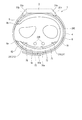
- FIG. 1 is a perspective view showing a configuration of a blood pressure measuring device according to an embodiment of the present invention.
- FIG. 2 is an explanatory view showing a state in which the blood pressure measuring device is worn on the wrist.
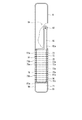
- FIG. 3 is a plan view showing the configuration of the cuff structure of the blood pressure measuring device.
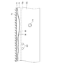
- FIG. 4 is a perspective view showing a part of the carla and the cuff structure of the blood pressure measuring device.
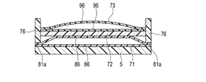
- FIG. 5 is a cross-sectional view schematically showing a state in which the blood pressure measuring device is worn on the wrist.
- FIG. 6 is an explanatory diagram showing a state in which the blood pressure measuring device is worn on the wrist and the pressure acting on the wrist.
- FIG. 1 is a perspective view showing a configuration of a blood pressure measuring device according to an embodiment of the present invention.
- FIG. 2 is an explanatory view showing a state in which the blood pressure measuring device is worn on the wrist.
- FIG. 3 is a plan view showing the configuration of the
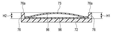
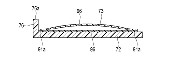
- FIG. 7 is a cross-sectional view showing the configuration of the cuff structure according to the modified example of the present invention.
- FIG. 8 is a cross-sectional view showing the configuration of the cuff structure according to the modified example of the present invention.
- FIG. 9 is a cross-sectional view showing the configuration of the cuff structure according to the modified example of the present invention.
- FIG. 10 is a cross-sectional view showing the configuration of the cuff structure according to the modified example of the present invention.
- FIG. 11 is a cross-sectional view showing the configuration of the cuff structure according to the modified example of the present invention.
- FIG. 12 is a side view showing the configuration of the back plate and the wall portion according to the modified example of the present invention.
- FIG. 13 is a side view showing the configuration of the back plate and the wall portion according to the modified example of the present invention.
- FIG. 14 is a side view showing the configuration of the back plate and the wall portion according to the modified example of the present invention.
- FIG. 15 is an explanatory view showing a state in which the blood pressure measuring device according to the modified example of the present invention is worn on the wrist.
- FIG. 16 is a plan view showing the configuration of the cuff structure of the blood pressure measuring device.
- FIG. 1 is a perspective view showing the configuration of the blood pressure measuring device 1.
- FIG. 2 is an explanatory view showing a state in which the blood pressure measuring device 1 is attached to the wrist 200.
- attaching the blood pressure measuring device 1 to the wrist 200 means that the blood pressure measuring device 1 is attached to the wrist 200 and the belt 4 which is an example of the fixture is fastened to fix the blood pressure measuring device 1 to the wrist 200.
- FIG. 3 is a plan view showing the configuration of the cuff structure 6 of the blood pressure measuring device 1.
- the pressing cuff 71 of the cuff structure 6 shows a state in which a part of the pressing cuff 71 is cut out.
- FIG. 4 is a perspective view showing a part of the carla 5 and the cuff structure 6 of the blood pressure measuring device 1.
- FIG. 5 is a cross-sectional view showing a state in which the blood pressure measuring device 1 is attached to the wrist 200.
- FIG. 6 is an explanatory diagram schematically showing a state in which the blood pressure measuring device 1 is attached to the wrist 200 and the pressure acting on the wrist 200.
- the blood pressure measuring device 1 includes a device main body 3, a belt 4 for fixing the device main body 3 to the wrist 200, a carla 5 arranged between the belt 4 and the wrist 200, and a cuff.
- the structure 6 and the like are provided.
- the device main body 3 includes, for example, a case 11, a display unit 12, and an operation unit 13. Further, the apparatus main body 3 includes a pump for expanding the cuff structure 6, a flow path portion for fluidly connecting the pump and the cuff structure 6, and a control board in the case 11.
- the case 11 includes an outer case 31 and a windshield 32 that covers an opening on the side opposite to the wrist 200 side of the outer case 31.
- the outer case 31 is formed in a cylindrical shape.
- the outer case 31 includes a pair of lugs 31a provided at symmetrical positions in the circumferential direction of the outer peripheral surface, and a spring rod 31b provided between the two pairs of lugs 31a, respectively.
- the windshield 32 is, for example, a circular glass plate.
- the display unit 12 is arranged directly below the windshield 32.
- the display unit 12 is electrically connected to the control board.
- the display unit 12 is, for example, a liquid crystal display or an organic electroluminescence display.
- the display unit 12 displays various information including the date and time, the blood pressure value such as the systolic blood pressure and the diastolic blood pressure, and the measurement result such as the heart rate.
- the operation unit 13 is configured so that commands from the user can be input.
- the operation unit 13 includes a plurality of buttons 41 provided on the case 11 and a sensor for detecting the operation of the buttons 41.
- a sensor for detecting the operation of the buttons 41 For example, three buttons 41 are provided.
- the belt 4 is an example of a fixture for fixing the blood pressure measuring device 1 while being attached to the wrist 200.
- the belt 4 includes a first belt 61 provided on one pair of lugs 31a and a spring rod 31b, and a second belt 62 provided on the other pair of lugs 31a and a spring rod 31b.
- the belt 4 is wrapped around the wrist 200 via the carla 5.
- the first belt 61 is a so-called parent and is configured in a band shape that can be connected to the second belt 62.
- the first belt 61 has a belt portion 61a and a buckle 61b.
- the belt portion 61a is formed in a band shape.
- the belt portion 61a is made of an elastically deformable resin material.
- the buckle 61b is provided at the other end of the belt portion 61a.
- the buckle 61b has a rectangular frame-shaped frame-shaped body 61e and a stick 61f rotatably attached to the frame-shaped body 61e.
- the second belt 62 is a so-called sword tip, and is configured in a band shape having a width that can be inserted into the frame-shaped body 61e.
- the second belt 62 is made of an elastically deformable resin material. Further, the second belt 62 has a plurality of small holes 62a into which the stick 61f is inserted. One end of the second belt 62 is supported by the other spring rod 31b.
- the first belt 61 and the second belt 62 are integrally connected by inserting the second belt 62 into the frame-shaped body 61e and inserting the rod 61f attached to the small hole 62a. Then, together with the outer case 31, it becomes an annular shape that follows the circumferential direction of the wrist 200.
- the belt 4 forms an annular shape that follows the circumferential direction of the wrist 200, thereby pressing the carla 5 and elastically deforming the carla 5 so as to follow the circumferential direction of the wrist 200 of the wearer of the blood pressure measuring device 1.
- the carla 5 is formed in a band shape that curves along the circumferential direction of the wrist 200.
- the carla 5 is formed so that one end 5a and the other end 5b are separated from each other.
- One end 5a is one end located on the palm side of the wrist 200 with the blood pressure measuring device 1 attached to the wrist 200.
- the other end 5b is one end located on the back side of the wrist 200 with the blood pressure measuring device 1 attached to the wrist 200.
- the outer peripheral surface on the other end 5b side is fixed to the apparatus main body 3.
- the carla 5 is made of, for example, a resin material.
- the carla 5 is formed so that the length from the device main body 3 to the other end 5b is shorter than the length from the device main body 3 to one end 5a.
- the short side from the device main body 3 to the other end 5b is arranged on the back side of the wrist 200.
- the longitudinal side of the carla 5 from the device main body 3 to one end 5a extends from the back side of the wrist 200 to the palm side of the wrist 200 through one side.
- Such a carla 5 is fixed to the outer case 31 with one end 5a and the other end 5b facing the first belt 61 of the belt 4.
- the carla 5 has a hardness having flexibility and shape retention.
- “flexibility” means that the shape is deformed in the radial direction when an external force of the belt 4 is applied to the carla 5.
- flexibility means that when the carla 5 is pressed by the belt 4, the shape of the side view is close to the wrist 200, follows the shape of the wrist 200, or follows the shape of the wrist 200. It means to transform.
- the shape-retaining property means that the carla 5 can maintain a preformed shape when no external force is applied.
- the shape retention means that in the present embodiment, the shape of the carla 5 can be maintained in a shape that is curved along the circumferential direction of the wrist 200.
- the cuff structure 6 is arranged on the inner peripheral surface of the carla 5.
- the carla 5 holds a part of the cuff structure 6 along the shape of the inner peripheral surface 5c of the carla 5.
- the carla 5 holds the cuff structure 6 by fixing the cuff structure 6 by a bonding layer provided between the carla 5 and the cuff structure 6.
- the bonding layer is, for example, an adhesive or double-sided tape.
- the cuff structure 6 includes a pressing cuff 71, a back plate 72, a sensing cuff 73, and a wall portion 76. Further, the cuff structure 6 includes a joining layer 75 for joining each structure and the carla 5 and the pressing cuff 71.
- the pressing cuff 71, the back plate 72, and the sensing cuff 73 are laminated and arranged on the carla 5.
- the pressing cuff 71 is fixed to the inner peripheral surface 5c of the carla 5.
- the back plate 72 is fixed to the inner peripheral surface of the wrist 200 of the pressing cuff 71 on the palm side from the inner peripheral surface of the pressing cuff 71 toward the wrist 200 side.
- the sensing cuff 73 is fixed to the inner peripheral surface of the back plate 72 on the palm side.
- Each member of the cuff structure 6 is fixed to a member adjacent to each other in the stacking direction by a joining layer.
- the pressing cuff 71 is fluidly connected to the pump via the flow path portion.
- the pressing cuff 71 is formed in a band shape extending in one direction.
- a part of the pressing cuff 71 is fixed to the inner peripheral surface 5c of the carla 5 by the joining layer.
- the pressing cuff 71 has a length capable of pressing the sensing cuff 73 toward the wrist 200 and pressing the back side of the wrist 200 with the blood pressure measuring device 1 attached.
- the pressing cuff 71 has, for example, a length of the inner peripheral surface 5c of the carla 5 extending from one end 5a to the other end 5b.
- the pressing cuff 71 includes an air bag 81 and a connecting portion 84 provided on the air bag 81.
- the configuration in which one of the air bags 81 is used has been described as an example, but the present invention is not limited to this.
- a plurality of air bags 81 may be provided, and the plurality of air bags 81 may be laminated.
- the plurality of air bags 81 to be laminated are fluidly communicated with each other in the stacking direction, for example.
- Such a pressing cuff 71 is configured by integrally welding a plurality of sheet members 86.
- the connection portion 84 is connected to the flow path portion of the apparatus main body 3. By connecting the connecting portion 84 to the flow path portion, the pressing cuff 71 is fluidly connected to the pump.
- the air bag 81 is a bag-shaped structure, and in the present embodiment, the blood pressure measuring device 1 has a configuration in which air is used by a pump.
- the bag-shaped structure may be a fluid bag that expands with the fluid.
- the air bag 81 is formed in the shape of a rectangular bag that is long in one direction. Further, the width of the air bag 81 in the lateral direction is set to be the same as the width of the carla 5 in the lateral direction.
- the air bag 81 is formed by, for example, combining two sheet members 86 and welding them by heat in a rectangular frame shape long in one direction as shown in FIG. 3 for the welding portion 81a.
- connection portion 84 is, for example, a nipple.
- the connection portion 84 is connected to the flow path portion of the apparatus main body 3.
- the connecting portion 84 is provided at a portion of the air bag 81 facing the device main body 3.
- the tip of the connecting portion 84 is exposed from the seat member 106 facing the carla 5 among the two seat members 86 constituting the air bag 81.
- the connecting portion 84 is connected to the flow path portion.
- the back plate 72 is formed in the shape of a plate that is long in one direction.
- the back plate 72 is attached to the outer surface of the sheet on the wrist 200 side of the pressing cuff 71 by the joining layer.
- the back plate 72 has a length facing the region where the arteries 210 and the tendons 220 exist, with the blood pressure measuring device 1 attached to the wrist 200.
- the back plate 72 has shape followability.
- the shape followability means a function in which the back plate 72 can be deformed so as to imitate the shape of the contacted portion of the wrist 200 to be arranged, and the back plate 72 faces the contacted portion of the wrist 200.
- the area of the wrist 200, where contact includes both direct contact and indirect contact via the sensing cuff 73.
- the back plate 72 has a plurality of grooves 72a extending in a direction orthogonal to the longitudinal direction on both main surfaces of the back plate 72.
- a plurality of grooves 72a are provided on both main surfaces of the back plate 72.
- the plurality of grooves 72a provided on both main surfaces face each other in the thickness direction of the back plate 72. Further, the plurality of grooves 72a are arranged at equal intervals in the longitudinal direction of the back plate 72.
- the back plate 72 Since the portion of the back plate 72 having the plurality of grooves 72a is thinner than the portion having the plurality of grooves 72a, the portion having the plurality of grooves 72a is easily deformed. Therefore, the back plate 72 follows the shape of the wrist 200. It is deformed and has a shape-following property that extends in the circumferential direction of the wrist 200.
- the back plate 72 is formed to have a length that covers the palm side of the wrist 200.
- the back plate 72 transmits the pressing force from the pressing cuff 71 to the main surface of the sensing cuff 73 on the back plate 72 side while following the shape of the wrist 200.
- the sensing cuff 73 is fluidly connected to the pump via the flow path portion of the device main body 3.
- the sensing cuff 73 is fixed to the main surface of the back plate 72 on the wrist 200 side by a bonding layer.
- the sensing cuff 73 has a length of contacting the region where the artery 210 of the wrist 200 exists with the blood pressure measuring device 1 attached to the wrist 200.
- the sensing cuff 73 has a length extending from the radial artery 211 of the artery 210 to the ulnar artery 212, as shown in FIG.
- the sensing cuff 73 is formed, for example, in the longitudinal direction and the width direction of the back plate 72, having the same shape as the back plate 72 or a shape smaller than the back plate 72. Air is supplied to the sensing cuff 73, and by being pressed by the inflated pressing cuff 71, the sensing cuff 73 presses the region where the artery 210 on the palm side of the wrist 200 exists via the inflated pressing cuff 71. The sensing cuff 73 is pressed toward the wrist 200 side via the back plate 72 by the expanded pressing cuff 71.
- the sensing cuff 73 includes, for example, one air bag 91, a flow path body 92 communicating with the air bag 91, and a connecting portion 93 provided at the tip of the flow path body 92. ..
- one main surface of the air bag 91 is fixed to the back plate 72.
- the sensing cuff 73 is joined to the main surface of the back plate 72 on the wrist 200 side by a joining layer.
- Such a sensing cuff 73 is configured by integrally welding two sheet members 96.
- the air bag 91 is a bag-shaped structure, and in the present embodiment, the blood pressure measuring device 1 has a configuration in which air is used by a pump.
- the bag-shaped structure may be a fluid bag that expands with the fluid.
- the air bag 91 is formed in a rectangular shape that is long in one direction.
- the air bag 91 is configured by, for example, combining two sheet members 96 that are long in one direction and welding them in a rectangular frame shape that is long in one direction by heat, as shown by the welding portion 91a in FIG.
- the flow path body 92 is integrally provided on a part of one edge of the air bag 91 in the longitudinal direction.
- the flow path body 92 is provided at an end portion of the air bag 91 near the device main body 3.
- the flow path body 92 is formed in a width smaller than the width in the lateral direction of the air bag 91 and is formed in a long shape in one direction, and the tip is formed in a circular shape.
- the flow path body 92 has a connecting portion 93 at the tip thereof.
- the flow path body 92 has a connecting portion 93 at the tip thereof.
- the flow path body 92 is connected to the flow path portion of the apparatus main body 3 via the connection portion 93, and constitutes a flow path between the flow path portion and the air bag 91.
- a part of the sheet member 96 adjacent to the region constituting the air bag 91 of the sheet member 96 is formed into a long frame shape in one direction. It is composed of welding by heat.
- the flow path body 92 and the connecting portion 93 are arranged on the carla 5 side with respect to the pressing cuff 71 by arranging a part of the flow path body 92 in, for example, a notch formed in the pressing cuff 71.
- the connecting portion 93 may be connected to the flow path portion of the apparatus main body 3 through, for example, a hole formed in the pressing cuff 71.
- the air bag 91 is configured such that a part of the welding portion 91a that welds the two sheet members 96 in a rectangular frame shape is non-welded and is continuous with the welding portion 92a constituting the flow path body 92.
- the air bag 91 and the flow path body 92 are fluidly communicated with each other.
- connection portion 93 is, for example, a nipple.
- the connecting portion 93 is provided at the tip of the flow path body 92. Further, the tip of the connecting portion 93 is exposed to the outside from the seat member 96 facing the carla 5 and the back plate 72 among the two seat members 96 constituting the flow path body 92.
- the connecting portion 93 is connected to the flow path portion.
- the wall portion 76 is provided along at least one of a pair of edge portions along the longitudinal direction of the sensing cuff 73. Further, the wall portion 76 has a length facing the region where the tendon 220 of the wrist 200 exists when the blood pressure measuring device 1 is attached to the wrist 200. In the present embodiment, as an example, as shown in FIG. 3, the wall portion 76 has a length extending from one end to the other end in the longitudinal direction of the air bag 91 of the sensing cuff 73. Further, the wall portion 76 is provided on the back plate 72, for example. The wall portion 76 may be integrally formed with the back plate 72. Alternatively, the wall portion 76 may be formed by fixing a member different from the back plate 72 to the back plate 72.
- the wall portion 76 is arranged at a position adjacent to each of the pair of edge portions of the back plate 72 along the longitudinal direction of the sensing cuff 73. That is, a pair of wall portions 76 is provided. Further, each of the pair of wall portions 76 is provided, for example, at an edge portion along the longitudinal direction of the back plate 72.
- the pair of wall portions 76 are curved along the carla 5 with the cuff structure 6 fixed to the carla 5.
- the wall portion 76 attaches the blood pressure measuring device 1 to the wrist 200 to supply air to the sensing cuff 73, and in a state where the pressing cuff 71 is inflated, the wall portion 76 is brought into close contact with the wrist 200 to hold the wrist 200. It has a height that allows the sensing cuff 73 to be brought into close contact with the wrist 200 while being pushed in.
- the height of the wall portion 76 is the height from the main surface of the back plate 72 on the wrist 200 side to the tip surface 76a of the wall portion 76 in the present embodiment.
- the blood pressure measuring device 1 is attached to the wrist 200, air is supplied to the sensing cuff 73, and the pressing cuff 71 is inflated, and the main surface of the back plate 72 on the wrist 200 side.
- the height H1 from the wall portion 76 to the tip surface 76a is higher than the height H2 from the main surface of the back plate 72 on the wrist 200 side to the protruding end of the sensing cuff 73 in the expanded state on the wrist 200 side.
- the height of the wall portion 76 is an example in the present embodiment, and the height of the wall portion 76 has a constant height from one end to the other end in the longitudinal direction of the wall portion 76.
- the wall portion 76 has a height that protrudes from the sensing cuff 73 when the sensing cuff 73 is inflated without the blood pressure measuring device 1 being attached to the wrist 200, for example.
- the non-wearing state in which the blood pressure measuring device 1 is not attached to the wrist 200 is a state in which the blood pressure measuring device 1 is not attached to the wrist 200. That is, the wrist 200 is not arranged in the carla 5.
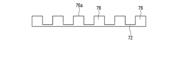
- each of the pair of wall portions 76 has a plurality of grooves 76b formed on the tip surface 76a.
- the plurality of grooves 76b extend in a direction orthogonal to the longitudinal direction of the tip surface 76a.
- the plurality of grooves 76b extend from one of the edges along the longitudinal direction of the tip surface 76a to the other edge.
- the plurality of grooves 76b are arranged at equal intervals in the longitudinal direction of the wall portion 76.
- the plurality of grooves 76b of the tip surface 76a of one wall portion 76 are formed in the same number as, for example, the grooves 72a of the back plate 72. Further, the plurality of grooves 76b are aligned with the grooves 72a of the back plate 72 in a direction orthogonal to the longitudinal direction of the tip surface 76a. Further, the extending direction of the plurality of grooves 76b is parallel to the extending direction of the plurality of grooves 72a.
- the groove 76b and the groove 72a of one tip surface 76a and the groove 76b of the other tip surface 76a are linear in a direction orthogonal to the longitudinal direction of the tip surface 76a in a plan view as shown in FIG. line up.
- the height of the pair of wall portions 76 is lower than that of the portion having the plurality of grooves 76b as compared with the portion having the plurality of grooves 76b, so that the portion having the plurality of grooves 76b is easily deformed. It deforms according to the shape and has a shape-following property extending in the circumferential direction of the wrist 200.
- the blood pressure measuring device 1 configured as described above, the blood pressure measuring device 1 is attached to the wrist 200, air is supplied to the sensing cuff 73, and the pressing cuff 71 is inflated, and the pair of wall portions 76 are attached to the wrist 200. Press on the area where the arteries 210 are located.
- the pair of wall portions 76 presses the region where the artery of the wrist 200 exists. Further, as the pressing cuff 71 is inflated, the wall portion 76 further presses the region where the artery 210 of the wrist 200 exists.
- the pair of wall portions 76 presses the region where the artery of the wrist 200 exists, so that the unevenness of the region where the artery of the wrist 200 exists becomes small.
- the unevenness of the wrist 200 is an unevenness caused by a living body such as a tendon 220, a bone, and a muscle of the wrist 200.
- the sensing cuff 73 is suitably brought into close contact with the wrist.
- the sensing cuff 73 is supplied with air, and even if the wrist 200 is pressed by the inflated pressing cuff 71, the sensing cuff 73 is crushed. Can be prevented.
- crushing means that the wrist 200 side and the back plate 72 side of the inner surface of the sensing cuff 73 come into contact with each other.
- the sensing cuff 73 can be uniformly inflated. Since the sensing cuff 73 can be uniformly expanded, the pressure inside the sensing cuff 73 can be made uniform. Therefore, as shown in FIG. 6, the pressure acting on the region where the sensing cuff 73 of the wrist 200 is in close contact can be made substantially constant.
- the pair of wall portions 76 presses the region where the artery of the wrist 200 exists, so that the wrist 200 follows the tip surface 76a of the wall portion 76.
- the wrist 200 preferably adheres to the region where the artery 210 of the wrist 200 exists.
- the pressure inside the sensing cuff 73 is made uniform, and the sensing cuff 73 is suitably in close contact with the wrist 200, so that the accuracy of blood pressure measurement can be improved.
- the wall portion 76 has a length facing the tendon 220 with the blood pressure measuring device 1 attached to the wrist 200, the tendon 220 can be pushed into the wrist 200. Therefore, the sensing cuff 73 can be brought into close contact with the region where the ulnar artery 212 exists from the radial artery 211 of the wrist 200.
- the blood pressure measuring device 1 is configured to include a pair of wall portions 76, the pair of wall portions 76 presses the wrist 200.
- the portion of the wrist 200 between the pair of wall portions 76 follows the tip surface 76a. Therefore, since the region of the wrist 200 that follows the tip surface 76a of the wall portion 76 can be increased, the sensing cuff 73 can be more preferably brought into close contact with the region where the artery 210 of the wrist 200 exists.
- the pair of wall portions 76 are supported by the back plate 72. Therefore, the pair of wall portions 76 can be stably pressed against the wrist 200 side.
- the wall portion 76 is pressed toward the wrist 200 by the back plate 72. Therefore, it is possible to prevent the stress generated on the surface of the pressing cuff 71 from becoming large when the blood pressure measuring device 1 is attached to the wrist 200 and air is supplied to the sensing cuff 73 to inflate the pressing cuff 71.
- the pair of wall portions 76 integrally with the back plate 72, it is possible to prevent the number of parts of the blood pressure measuring device 1 from increasing. Therefore, the efficiency of the assembling work of the cuff structure 6 can be improved, so that the efficiency of the assembling work of the blood pressure measuring device 1 can be improved.
- the back plate 72 can be easily curved, so that the efficiency of the work of fixing the back plate 72 to the carla 5 can be improved.
- the carla 5 is deformed according to the wrist 200 by tightening the belt 4 when the blood pressure measuring device 1 is attached to the wrist 200.
- the wall portion 76 can be easily curved by the plurality of grooves 76b, the efficiency of the attachment work of the blood pressure measuring device 1 can be improved.
- a plurality of grooves 76b formed on the respective tip surfaces 76a of the pair of wall portions 76 are aligned with the grooves 72a of the back plate 72 in a direction orthogonal to the longitudinal direction of the wall portions 76, whereby the back plate 72 and the back plate 72 and The bending points of the wall portion 76 can be matched.
- the back plate 72 is curved as a whole by bending in the groove 72a
- the wall portion 76 is curved as a whole by bending in the groove 76b.
- the wall portion 76 has a height that protrudes from the sensing cuff 73 in a state where the blood pressure measuring device 1 is not attached to the wrist 200 and the sensing cuff 73 is inflated. Therefore, the blood pressure measuring device 1 is attached to the wrist 200, and the wall portion 76 presses the wrist 200 in a state where the pressing cuff 71 is not inflated.
- the wall portion 76 supplies air to the sensing cuff 73 in a state where the unevenness of the region where the artery of the wrist 200 exists is reduced, and the pressing cuff 71 is expanded. As a result, air can be smoothly supplied to the sensing cuff 73.
- the blood pressure measuring accuracy can be improved.
- the wall portion 76 has the blood pressure measuring device 1 attached to the wrist 200 to supply air to the sensing cuff 73, and the wall portion 76 is moved from the sensing cuff 73 in a state where the pressing cuff 71 is inflated.
- the sensing cuff 73 has a height that allows it to come into close contact with the region where the artery 210 of the wrist 200 exists.
- the wall portion 76 has a configuration in which the wall portion 76 has a height protruding from the sensing cuff 73 in a state where the blood pressure measuring device 1 is not attached to the wrist 200 and the sensing cuff 73 is inflated.
- rice field is not limited to this.
- the wall portion 76 has the blood pressure measuring device 1 attached to the wrist 200 to supply air to the sensing cuff 73, and in a state where the pressing cuff 71 is inflated, the wall portion 76 protrudes from the sensing cuff 73 and the sensing cuff 73 is attached to the wrist 200. If the arteries can be brought into close contact with the region, the wall portion 76 is lower than the sensing cuff 73 in a state where the blood pressure measuring device 1 is not attached to the wrist 200 and the sensing cuff 73 is inflated, as shown in the modified example shown in FIG. It may be (H1 ⁇ H2). In FIG. 7, the pressing cuff 71 and the carla 5 are omitted.
- the thickness of the sensing cuff 73 becomes the thickness of the sensing cuff 73 shown in FIG.
- the wall portion 76 protrudes from the sensing cuff 73.
- the wall portion 76 may have the same height as the sensing cuff 73 in a state where the blood pressure measuring device 1 is not attached to the wrist 200 and the sensing cuff 73 is inflated.
- Good (H1 H2).
- the thickness of the sensing cuff 73 becomes larger than the thickness shown in FIG. It becomes smaller and the wall portion 76 protrudes from the sensing cuff 73.
- the wall portion 76 has a height at which the wall portion 76 protrudes from the sensing cuff 73 in a state where the blood pressure measuring device 1 is not attached to the wrist 200 and the sensing cuff 73 is inflated.
- the configuration may have the same height as the sensing cuff 73.
- the wall portion 76 has a structure in which the blood pressure measuring device 1 is not attached to the wrist 200 and the sensing cuff 73 is inflated and has a height protruding from the sensing cuff 73, so that the belt 4 can be tightened. Air is supplied to the sensing cuff 73 in a state where the unevenness of the wrist 200 is reduced by the wall portion 76.
- the sensing cuff 73 can be more preferably brought into close contact with the region where the artery 210 of the wrist 200 exists. Therefore, it is preferable that the wall portion 76 has a height that protrudes from the sensing cuff 73 in a state where the blood pressure measuring device 1 is not attached to the wrist 200 and the sensing cuff 73 is inflated.
- the wall portion 76 is integrally formed with the back plate 72 has been described as an example, but the present invention is not limited to this.
- the wall portion 76 may be formed separately from the back plate 72.
- the wall portion 76 may be integrally formed with the pressing cuff 71.
- the cuff structure 6 does not include the back plate 72
- at least the region of the sheet constituting the surface of the pressing cuff 71 on the wrist 200 side where the sensing cuff 73 is fixed is the same as that of the back plate 72.
- the sensing cuff 73 can be supported.
- the wall portion 76 may be integrally formed with the pressing cuff 71.
- the wall portion 76 When the wall portion 76 is formed on the pressing cuff 71 as described above, the wall portion 76 is formed on the welding portion 81a of the pressing cuff 71 as in the modified example shown in FIG. 9, for example.
- the welded portion 81a does not move to the wrist 200 side even if the pressing cuff 71 expands. Therefore, when the wall portion 76 is formed on the welded portion 81a, the wall portion 76 does not move to the wrist 200 side even if the pressing cuff 71 expands.
- the wall portion 76 is the blood pressure measuring device 1. Has a height that presses on the region of the wrist 200 where the artery 210 resides.
- the wall portion 76 may be integrally formed with the sensing cuff 73 as in the modified example shown in FIG.
- the wall portion 76 may be provided on the welding portion 91a.
- the pressing cuff 71 and the back plate 72 are not shown.
- the wall portion 76 may be formed along one of a pair of edge portions along the longitudinal direction of the sensing cuff 73.
- the wall portion 76 is more preferably the finger side of the hand with respect to the sensing cuff 73 and the shoulder side with respect to the sensing cuff 73. The position where the wall portion 76 is formed is selected so that it is located on the side where the blood pressure can be measured.
- the configuration in which the wall portion 76 has a constant height from one end to the other end in the direction extending along the sensing cuff 73 has been described as an example, but the present invention is not limited to this. In another example, the height of the wall portion 76 may not be constant from one end to the other end in the direction extending along the sensing cuff 73 of the wall portion 76.
- FIG. 12 shows a configuration in which the wall portion 76 is provided on the back plate 72 as an example, and shows the side surfaces of the wall portion 76 and the back plate 72.
- a configuration in which the tip surface 76a of the wall portion 76 is formed on a curved surface is shown as an example.
- the portion of the wall portion 76 facing the hard living body such as the tendon 220, bone, and muscle is configured to have a higher shape than the others, so that the hard portion of the wrist 200 can be formed. It becomes possible to push it in. As a result, the unevenness of the wrist 200 can be reduced.
- the wall portion 76 has a length extending from one end to the other end of the air bag 91 of the sensing cuff 73 in the longitudinal direction. In other words, it has a length extending from one end to the other end of the edge along the longitudinal direction of the sensing cuff 73. Further, in the present embodiment, the wall portion 76 has a length extending from one end to the other end of the back plate 72 in the longitudinal direction, as an example.
- the wall portion 76 may be provided along at least one end and a part between the other ends of the edge portion along the longitudinal direction of the sensing cuff 73.
- the wall portion 76 may be formed only on a portion facing a hard living body such as a tendon 220, a bone, or a muscle while the blood pressure measuring device 1 is attached to the wrist 200. ..
- FIG. 13 shows a configuration in which the wall portion 76 extends along a part between one end and the other end of the sensing cuff 73 in the longitudinal direction.
- FIG. 13 shows, as an example, a configuration in which the wall portion 76 is integrally formed with the back plate 72, and shows the side surfaces of the wall portion 76, the back plate 72, and the air bag 91 of the sensing cuff 73. ..
- FIG. 14 shows a configuration in which the wall portion 76 is formed on the back plate 72 as an example, and shows the side surfaces of the wall portion 76 and the back plate 72.
- the cuff structure 6 has been described as an example in which a part of the pressing cuff 71 is arranged on the back side of the wrist 200 with the blood pressure measuring device 1 attached to the wrist 200. Not limited to this.
- the cuff structure 6 includes a pressing cuff 71 and a tension cuff 74 that is separate from the pressing cuff 71 as a cuff that is arranged on the back side of the wrist 200 with the blood pressure measuring device 1 attached to the wrist 200. There may be.
- FIG. 15 is an explanatory view showing a state in which the blood pressure measuring device 1 according to the modified example is attached to the wrist 200.
- FIG. 16 is a plan view showing the cuff structure 6A of the blood pressure measuring device 1 according to the modified example.
- FIG. 16 shows the surface of the cuff structure 6A on the wrist 200 side when the blood pressure measuring device 1 is attached to the wrist 200.
- the cuff structure 6A includes a pressing cuff 71A, a back plate 72, a sensing cuff 73, and a tension cuff 74.
- the cuff structure 6A includes a joining layer for joining each structure and the carla 5 and the pressing cuff 71.
- the pressing cuff 71A is fluidly connected to the pump via the flow path portion.
- the pressing cuff 71A presses the back plate 72 and the sensing cuff 73 toward the wrist 200 by expanding.
- the pressing cuff 71A is formed in a band shape extending in one direction.
- the pressing cuff 71A is fixed to the inner peripheral surface of the carla 5 by the joining layer.
- the pressing cuff 71A includes an air bag 81, a flow path body 83 communicating with the air bag 81, and a connecting portion 84 provided at the tip of the flow path body 83.
- the flow path body 83 is integrally provided, for example, in a part of the edge portion at one end in the longitudinal direction of the air bag 81.
- the flow path body 83 is provided at an end portion of the air bag 81 near the device main body 3.
- the flow path body 83 is formed in a width smaller than the width in the lateral direction of the air bag 81 and is formed in a long shape in one direction, and the tip is formed in a circular shape.
- the flow path body 83 has a connecting portion 84 at the tip thereof.
- a part of the sheet member 86 adjacent to the region forming the air bag 81 of the sheet member 86 is formed into a long frame shape in one direction. It is composed of welding by heat.
- the air bag 81 provided with the flow path body 83, a part of the welding portion 81a for welding the two sheet members 86 in a rectangular frame shape is non-welded and is continuous with the welding portion 83a constituting the flow path body 83.
- the air bag 81 fluidly communicates with the flow path body 83.
- the connecting portion 84 is connected to the flow path portion.
- the tension cuff 74 is fluidly connected to the pump via the flow path portion.
- the tension cuff 74 is fixed to the back side of the wrist 200 of the carla 5.
- the tension cuff 74 pulls the belt 4 and the carla 5 toward the back of the wrist 200 by pressing the carla 5 so as to be separated from the wrist 200 by expanding.
- the tension cuff 74 includes, for example, a plurality of air bags 101 and a connecting portion 103 provided in the air bag 101 facing the carla 5.
- the plurality of air bags 101 are, for example, six-layer air bags 101.
- the air bag 101 is a bag-shaped structure, and in the present embodiment, the blood pressure measuring device 1A has a configuration in which air is used by a pump.
- the bag-shaped structure may be a fluid bag that expands with the fluid.
- the plurality of air bags 101 are laminated and fluidly communicate with each other in the stacking direction.
- Such a tension cuff 74 is configured by integrally welding a plurality of sheet members 106. Further, the tension cuff 74 is fixed to the back side of the wrist 200 of the carla 5. That is, the flow path body 83 of the pressing cuff 71A and the flow path body 92 of the sensing cuff 73 are arranged between the back side of the wrist 200 of the carla 5 and the tension cuff 74.
- the tension cuff 74 has the thickness at the time of expansion in the expansion direction, in the present embodiment, in the direction opposite to the carla 5 and the wrist 200, the thickness at the time of expansion of the pressing cuff 71A in the expansion direction, and the sensing.
- the cuff 73 is configured to be thicker than the thickness at the time of expansion in the expansion direction. That is, the air bag 101 of the tension cuff 74 has a layer structure larger than that of the air bag 81A of the pressing cuff 71A and the air bag 91 of the sensing cuff 73, and the thickness when expanded from the carla 5 toward the wrist 200 is increased. It is thicker than the pressing cuff 71A and the sensing cuff 73.
- the air bag 101 is formed in the shape of a rectangular bag that is long in one direction. Further, the width of the air bag 101 in the lateral direction is set to be the same as the width of the carla 5 in the lateral direction.
- the air bag 101 is formed by, for example, combining two sheet members 106 and welding them in a rectangular frame shape long in one direction by heat, as shown in FIG. 16 showing the welding portion 101a.
- the six-layer air bag 101 fluidly communicates with each other through openings provided in the sheet members 106 facing each other.
- connection portion 103 is, for example, a nipple.
- the connecting portion 103 is provided in the air bag 101 arranged adjacent to the carla 5.
- the tip of the connecting portion 103 is exposed from the seat member 106 facing the carla 5 among the two seat members 106 constituting the air bag 101.
- the connection portion 103 is connected to the flow path portion of the apparatus main body 3.
- the present invention is not limited to the above embodiment, and can be variously modified at the implementation stage without departing from the gist thereof.
- each embodiment may be carried out in combination as appropriate as possible, and in that case, the combined effect can be obtained.
- the above-described embodiment includes inventions at various stages, and various inventions can be extracted by an appropriate combination in a plurality of disclosed constitutional requirements. For example, even if some constituent requirements are deleted from all the constituent requirements shown in the embodiment, if the problem can be solved and the effect is obtained, the configuration in which the constituent requirements are deleted can be extracted as an invention.
Landscapes
- Health & Medical Sciences (AREA)
- Life Sciences & Earth Sciences (AREA)
- Surgery (AREA)
- Animal Behavior & Ethology (AREA)
- Pathology (AREA)
- Engineering & Computer Science (AREA)
- Biomedical Technology (AREA)
- Heart & Thoracic Surgery (AREA)
- Medical Informatics (AREA)
- Molecular Biology (AREA)
- Physics & Mathematics (AREA)
- Biophysics (AREA)
- General Health & Medical Sciences (AREA)
- Public Health (AREA)
- Veterinary Medicine (AREA)
- Cardiology (AREA)
- Vascular Medicine (AREA)
- Ophthalmology & Optometry (AREA)
- Dentistry (AREA)
- Physiology (AREA)
- Measuring Pulse, Heart Rate, Blood Pressure Or Blood Flow (AREA)
Priority Applications (3)
| Application Number | Priority Date | Filing Date | Title |
|---|---|---|---|
| CN202180018136.3A CN115209797B (zh) | 2020-03-16 | 2021-02-12 | 袖带构造体和血压测定装置 |
| DE112021000570.7T DE112021000570T5 (de) | 2020-03-16 | 2021-02-12 | Manschettenstruktur und blutdruckmessvorrichtung |
| US17/930,958 US20230000373A1 (en) | 2020-03-16 | 2022-09-09 | Cuff structure and blood pressure measurement device |
Applications Claiming Priority (2)
| Application Number | Priority Date | Filing Date | Title |
|---|---|---|---|
| JP2020-045264 | 2020-03-16 | ||
| JP2020045264A JP7556200B2 (ja) | 2020-03-16 | 2020-03-16 | カフ構造体、及び、血圧測定装置 |
Related Child Applications (1)
| Application Number | Title | Priority Date | Filing Date |
|---|---|---|---|
| US17/930,958 Continuation US20230000373A1 (en) | 2020-03-16 | 2022-09-09 | Cuff structure and blood pressure measurement device |
Publications (1)
| Publication Number | Publication Date |
|---|---|
| WO2021186977A1 true WO2021186977A1 (ja) | 2021-09-23 |
Family
ID=77768068
Family Applications (1)
| Application Number | Title | Priority Date | Filing Date |
|---|---|---|---|
| PCT/JP2021/005331 Ceased WO2021186977A1 (ja) | 2020-03-16 | 2021-02-12 | カフ構造体、及び、血圧測定装置 |
Country Status (5)
| Country | Link |
|---|---|
| US (1) | US20230000373A1 (enExample) |
| JP (1) | JP7556200B2 (enExample) |
| CN (1) | CN115209797B (enExample) |
| DE (1) | DE112021000570T5 (enExample) |
| WO (1) | WO2021186977A1 (enExample) |
Families Citing this family (1)
| Publication number | Priority date | Publication date | Assignee | Title |
|---|---|---|---|---|
| JP7472557B2 (ja) * | 2020-03-12 | 2024-04-23 | オムロンヘルスケア株式会社 | カフ構造体、及び血圧測定装置 |
Citations (2)
| Publication number | Priority date | Publication date | Assignee | Title |
|---|---|---|---|---|
| JP2009213767A (ja) * | 2008-03-12 | 2009-09-24 | Omron Healthcare Co Ltd | 血圧情報測定装置 |
| JP2018161382A (ja) * | 2017-03-27 | 2018-10-18 | オムロン株式会社 | 血圧計、血圧測定装置及び血圧測定方法 |
Family Cites Families (6)
| Publication number | Priority date | Publication date | Assignee | Title |
|---|---|---|---|---|
| JP3039934B2 (ja) * | 1989-06-13 | 2000-05-08 | コーリン電子株式会社 | 圧脈波検出装置 |
| JP2798764B2 (ja) * | 1990-01-09 | 1998-09-17 | コーリン電子株式会社 | 半導体圧脈波センサ |
| DE60032837T2 (de) * | 1999-02-22 | 2007-06-28 | Seiko Epson Corp. | Blutdruckmessungsvorrichtung und vorrichtung zum nachweis von pulswellen |
| JP6830353B2 (ja) * | 2016-12-28 | 2021-02-17 | オムロン株式会社 | 血圧計および血圧測定方法並びに機器 |
| JP6976842B2 (ja) | 2017-12-28 | 2021-12-08 | オムロンヘルスケア株式会社 | 血圧測定装置 |
| JP7472557B2 (ja) * | 2020-03-12 | 2024-04-23 | オムロンヘルスケア株式会社 | カフ構造体、及び血圧測定装置 |
-
2020
- 2020-03-16 JP JP2020045264A patent/JP7556200B2/ja active Active
-
2021
- 2021-02-12 CN CN202180018136.3A patent/CN115209797B/zh active Active
- 2021-02-12 WO PCT/JP2021/005331 patent/WO2021186977A1/ja not_active Ceased
- 2021-02-12 DE DE112021000570.7T patent/DE112021000570T5/de active Pending
-
2022
- 2022-09-09 US US17/930,958 patent/US20230000373A1/en active Pending
Patent Citations (2)
| Publication number | Priority date | Publication date | Assignee | Title |
|---|---|---|---|---|
| JP2009213767A (ja) * | 2008-03-12 | 2009-09-24 | Omron Healthcare Co Ltd | 血圧情報測定装置 |
| JP2018161382A (ja) * | 2017-03-27 | 2018-10-18 | オムロン株式会社 | 血圧計、血圧測定装置及び血圧測定方法 |
Also Published As
| Publication number | Publication date |
|---|---|
| CN115209797A (zh) | 2022-10-18 |
| CN115209797B (zh) | 2025-08-26 |
| US20230000373A1 (en) | 2023-01-05 |
| JP2021145706A (ja) | 2021-09-27 |
| DE112021000570T5 (de) | 2022-12-15 |
| JP7556200B2 (ja) | 2024-09-26 |
Similar Documents
| Publication | Publication Date | Title |
|---|---|---|
| JP6849488B2 (ja) | 血圧計、血圧測定方法および機器 | |
| WO2021182014A1 (ja) | カフ構造体、及び血圧測定装置 | |
| JP2017209433A5 (enExample) | ||
| US11653842B2 (en) | Blood pressure measuring device | |
| US12059236B2 (en) | Blood pressure measurement device | |
| JP2017209434A5 (enExample) | ||
| US11647912B2 (en) | Blood pressure measuring device | |
| US11529063B2 (en) | Blood pressure measuring device | |
| EP1952759B1 (en) | Apparatus for measuring biological data | |
| WO2021186977A1 (ja) | カフ構造体、及び、血圧測定装置 | |
| US11638531B2 (en) | Blood pressure measuring device and method of manufacturing blood pressure measuring device | |
| US20240197189A1 (en) | Biological information measurement device | |
| US20240041337A1 (en) | Blood pressure measurement device | |
| US11653879B2 (en) | Blood pressure measuring device | |
| US20240180437A1 (en) | Blood pressure measurement device | |
| WO2021182015A1 (ja) | カフ構造体、及び血圧測定装置 | |
| US11534073B2 (en) | Blood pressure measuring device | |
| JP2023146522A (ja) | 血圧測定装置 |
Legal Events
| Date | Code | Title | Description |
|---|---|---|---|
| 121 | Ep: the epo has been informed by wipo that ep was designated in this application |
Ref document number: 21769877 Country of ref document: EP Kind code of ref document: A1 |
|
| 122 | Ep: pct application non-entry in european phase |
Ref document number: 21769877 Country of ref document: EP Kind code of ref document: A1 |
|
| WWG | Wipo information: grant in national office |
Ref document number: 202180018136.3 Country of ref document: CN |