WO2021186671A1 - メカニカルキー、及びカードキー - Google Patents
メカニカルキー、及びカードキー Download PDFInfo
- Publication number
- WO2021186671A1 WO2021186671A1 PCT/JP2020/012304 JP2020012304W WO2021186671A1 WO 2021186671 A1 WO2021186671 A1 WO 2021186671A1 JP 2020012304 W JP2020012304 W JP 2020012304W WO 2021186671 A1 WO2021186671 A1 WO 2021186671A1
- Authority
- WO
- WIPO (PCT)
- Prior art keywords
- key
- division
- thickness direction
- mechanical
- pattern
- Prior art date
- Legal status (The legal status is an assumption and is not a legal conclusion. Google has not performed a legal analysis and makes no representation as to the accuracy of the status listed.)
- Ceased
Links
Images



Classifications
-
- E—FIXED CONSTRUCTIONS
- E05—LOCKS; KEYS; WINDOW OR DOOR FITTINGS; SAFES
- E05B—LOCKS; ACCESSORIES THEREFOR; HANDCUFFS
- E05B49/00—Electric permutation locks; Circuits therefor ; Mechanical aspects of electronic locks; Mechanical keys therefor
- E05B49/002—Keys with mechanical characteristics, e.g. notches, perforations, opaque marks
-
- E—FIXED CONSTRUCTIONS
- E05—LOCKS; KEYS; WINDOW OR DOOR FITTINGS; SAFES
- E05B—LOCKS; ACCESSORIES THEREFOR; HANDCUFFS
- E05B19/00—Keys; Accessories therefor
- E05B19/0082—Keys or shanks being removably stored in a larger object, e.g. a remote control or a key fob
-
- A—HUMAN NECESSITIES
- A45—HAND OR TRAVELLING ARTICLES
- A45C—PURSES; LUGGAGE; HAND CARRIED BAGS
- A45C11/00—Receptacles for purposes not provided for in groups A45C1/00-A45C9/00
- A45C11/32—Bags or wallets for holding keys
- A45C11/325—Spare-key holders
- A45C11/326—Card-like holders
-
- E—FIXED CONSTRUCTIONS
- E05—LOCKS; KEYS; WINDOW OR DOOR FITTINGS; SAFES
- E05B—LOCKS; ACCESSORIES THEREFOR; HANDCUFFS
- E05B19/00—Keys; Accessories therefor
- E05B19/14—Double or multiple keys, e.g. with two or more bows or bits
-
- E—FIXED CONSTRUCTIONS
- E05—LOCKS; KEYS; WINDOW OR DOOR FITTINGS; SAFES
- E05B—LOCKS; ACCESSORIES THEREFOR; HANDCUFFS
- E05B19/00—Keys; Accessories therefor
- E05B19/18—Keys adjustable before use
Definitions
- the present invention relates to a mechanical key and a card key.
- a vehicle or the like may be equipped with a mechanical key that is used when the battery of the communication mobile key is exhausted, for example.
- a mechanical key there is one that can be divided into a plurality of divided keys in the thickness direction and is housed and held in a card case in the divided state to form a card key (for example, Patent Document). 1). With such a card key, the mechanical key is held in a thin state and can be carried by the user.
- the mechanical key as described above has a key pattern recessed in the thickness direction, and the shape of the key pattern is formed only on one of the split keys.
- the side wall having a shape corresponding to the pattern peculiar to the key and the bottom of the key pattern are formed into one divided key, it is difficult to manufacture and to reduce the thickness.
- An object of the present invention is to provide a mechanical key and a card key that are thin and easy to manufacture.
- the mechanical key for solving the above problem is a mechanical key having a key pattern recessed in the thickness direction and capable of being divided into a plurality of division keys in the thickness direction. At least one has a key pattern configuration penetrating portion that penetrates in the thickness direction in a shape corresponding to the key pattern.
- At least one of the split keys has a key pattern configuration penetrating portion that penetrates in the thickness direction in a shape corresponding to the key pattern, and the bottom portion of the key pattern is not provided.
- the bottom portion of the key pattern is not provided.
- the card key for solving the above problem includes a mechanical key and a card case having a storage portion capable of holding the divided keys arranged in the direction orthogonal to the thickness direction.
- the mechanical key in addition to the effect of the mechanical key described above, the mechanical key can be held in a thin state and can be carried by the user.
- the mechanical key and card key of the present invention can be made thinner and easily manufactured.
- the perspective view of the card key in one Embodiment. An exploded perspective view of a card key in one embodiment.
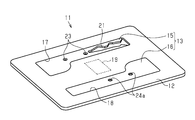
- the card key 11 includes a card case 12 and a mechanical key 13 that can be accommodated and held in the card case 12.
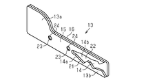
- the mechanical key 13 has a key pattern 14 recessed in the thickness direction.
- the mechanical key 13 is formed in a plate shape and has a grip portion 13a and a key portion 13b extending from the grip portion 13a, and the key pattern 14 extends from the tip of the key portion 13b toward the grip portion 13a. It is recessed in the thickness direction while being formed.
- the mechanical key 13 can be divided into a first division key 15 and a second division key 16 as two division keys in the thickness direction.
- the card case 12 has accommodating portions 17 and 18 capable of holding the divided first division key 15 and the second division key 16 side by side in the direction orthogonal to the thickness direction.
- the accommodating portions 17 and 18 of the present embodiment are recessed in the plate thickness direction of the card case 12, and the first division key 15 and the second division key 16 can be inserted from the plate thickness direction, respectively.
- a communication device 19 corresponding to a transponder, NFC (Near Field Communication), or the like is embedded.
- the first division key 15 has a key pattern configuration penetrating portion 21 that penetrates in the thickness direction in a shape corresponding to the key pattern 14. That is, the key pattern 14 recessed in the thickness direction of the mechanical key 13 is composed of a side wall 14a having a shape corresponding to the unique pattern of the key pattern 14 and a bottom portion 14b which is the bottom in the recessing direction. ..
- the side wall 14a of the key pattern 14 is composed of the key pattern constitution penetrating portion 21 of the first division key 15, and the bottom portion 14b of the key pattern 14 is composed of the flat surface 22 of the second division key 16.
- the first division key 15 and the second division key 16 have a female fitting portion 23 or a male fitting portion 24 as fitting portions that are fitted to each other in the thickness direction.
- the first division key 15 is provided with a female fitting portion 23 penetrating in the thickness direction.
- a pair of female fitting portions 23 are provided in the longitudinal direction of the first division key 15.
- the second division key 16 is provided with a male fitting portion 24 that bulges in the thickness direction.
- a pair of male fitting portions 24 are provided in the longitudinal direction of the second division key 16.
- a recess 24a for extruding and bulging the male fitting portion 24 on the surface opposite to the side on which the male fitting portion 24 is formed see FIGS. 1 and 2). ) Is formed.
- the first division key 15 and the second division key 16 can be used as the mechanical key 13 by superimposing the male fitting portion 24 on the female fitting portion 23 while being fitted.
- first division key 15 and the second division key 16 described above are individually molded. Specifically, the first division key 15 is formed by punching so that a key pattern configuration penetrating portion 21 having a shape corresponding to a key pattern 14 having a unique pattern different for each mechanical key 13 is formed. Further, the second division key 16 is formed by punching as a common part regardless of the pattern of the key pattern 14.
- the divided first division key 15 and the second division key 16 are arranged in the direction orthogonal to the thickness direction, and the accommodating portions 17, 18 of the card case 12 are arranged.
- the mechanical key 13 is held in a thin state and can be carried by the user as a thin card key 11.
- the first division key 15 and the second division key 16 are taken out from the card case 12, and the male fitting portion 24 is fitted to the female fitting portion 23.
- the first division key 15 and the second division key 16 are overlapped with each other so that the user can use the mechanical key 13.
- the first division key 15 penetrates in the thickness direction in a shape corresponding to the key pattern 14. It is assumed that the key pattern configuration penetrating portion 21 is provided. Therefore, the first division key 15 is configured so that the bottom 14b of the key pattern 14 is not provided, and can be made thinner while maintaining the depth of the key pattern 14 as compared with the case where the division key has the bottom, for example. Become. Further, since the first division key 15 has a key pattern configuration penetrating portion 21 penetrating in the thickness direction, it can be easily manufactured by punching, for example.
- the first division key 15 has a shape that also has a bottom portion 14b of the key pattern 14, it cannot be manufactured by punching, but since it has a shape that does not have a bottom portion 14b, it can be easily manufactured by punching. can.
- the first division key 15 and the second division key 16 are not integrally molded products, but are individually molded. Therefore, for example, only the first division key 15 having the key pattern configuration penetration portion 21 is molded into a shape corresponding to the key pattern 14 of the unique pattern, and the second division key having no key pattern configuration penetration portion 21 is formed. 16 can be manufactured as a common component regardless of the pattern of the key pattern 14.
- first division key 15 and the second division key 16 have a female fitting portion 23 or a male fitting portion 24 as fitting portions that are fitted to each other in the thickness direction, the first division key 15 And the second division key 16 are superposed at suitable positions, and can be satisfactorily used as the mechanical key 13.
- the card key 11 has accommodating portions 17 and 18 capable of holding the mechanical key 13 and the divided first division key 15 and the second division key 16 side by side in the direction orthogonal to the thickness direction. Since the card case 12 is provided, the mechanical key 13 can be held in a thin state and can be carried by the user.
- the first division key 15 and the second division key 16 are not integrally molded products but are individually molded, but the present invention is not limited to this, and for example, as shown in FIG.
- the first division key 15 and the second division key 16 may be integrally molded via the thin hinge portion 31. By doing so, for example, the number of parts of the mechanical key 13 becomes one, and one of the first division key 15 and the second division key 16 is not lost.
- the first division key 15 and the second division key 16 have a female fitting portion 23 or a male fitting portion 24 as fitting portions that are fitted to each other in the thickness direction.
- the present invention is not limited to this, and the female fitting portion 23 and the male fitting portion 24 may not be provided. Further, the shapes and numbers of the female fitting portion 23 and the male fitting portion 24 may be changed.
- the card key 11 is attached so as to cover the first division key 15 and the second division key 16 in the accommodating portions 17 and 18 of the card case 12. It may have a film seal to be used. Further, the accommodating portions 17 and 18 may have a shape in which the first division key 15 and the second division key 16 are press-fitted and fixed or engaged and fixed. Further, in the above embodiment, the accommodating portions 17 and 18 are recessed in the plate thickness direction of the card case 12, but the present invention is not limited to this, and the accommodating portions 17 and 18 are recessed in the direction orthogonal to the plate thickness direction and from the same direction. It is also possible that the first division key 15 and the second division key 16 can be inserted respectively.
- the key pattern 14 of the mechanical key 13 is a so-called inner groove type (see FIG. 3) formed inside the key portion 13b in the width direction, but is recessed in the thickness direction.
- Other types of key patterns may be used as long as they form a unique pattern according to the shape seen from the thickness direction.
- the key pattern 32 may be a so-called outer mountain type formed on both sides of the key portion 13a in the width direction.
- the key pattern 33 may be a so-called dimple type composed of a large number of independent key recesses 33a.
- the mechanical key 13 can be divided into a first division key 15 and a second division key 16 in the thickness direction, but the mechanical key 13 can be divided into three or more division keys. May be.
- a mechanical key has a key pattern on both sides, and can be disassembled into three divided keys in the thickness direction, and two divided keys corresponding to both sides of the mechanical key penetrate in the thickness direction.
- Pattern configuration A configuration having a penetrating portion may be used.
- the first division key 15 and the second division key 16 are formed by punching, but the present invention is not limited to this, and the first division key 15 and the second division key 16 may be formed by another manufacturing method.
- the card case 12 is assumed to have the communication device 19, but the present invention is not limited to this, and the card case may be a card case that does not have the communication device 19.
Landscapes
- Lock And Its Accessories (AREA)
- Telephone Set Structure (AREA)
- Supports Or Holders For Household Use (AREA)
Abstract
薄型化及び容易な製造を可能としたメカニカルキーを提供する。メカニカルキー(13)は、厚さ方向に凹設されたキーパターン(14)を有し、厚さ方向に第1分割キー(15)と第2分割キー(16)とに分割可能とされる。そして、第1分割キー(15)は、キーパターン(14)に対応した形状で厚さ方向に貫通するキーパターン構成貫通部(21)を有する。
Description
本発明は、メカニカルキー、及びカードキーに関する。
従来、車両等には、例えば、通信携帯キーの電池が切れた際等に使用されるメカニカルキーが付属される場合がある。そして、このようなメカニカルキーとしては、厚さ方向に複数枚の分割キーに分割可能とされ、分割された状態でカードケースに収容保持されてカードキーを構成するものがある(例えば、特許文献1参照)。このようなカードキーでは、メカニカルキーを薄い状態で保持して利用者が携帯可能となる。
ところで、上記したようなメカニカルキーは、厚さ方向に凹設されたキーパターンを有しており、そのキーパターンの形状が一方の分割キーのみに形成されている。しかしながら、上記メカニカルキーでは、キー固有のパターンに対応した形状の側壁とキーパターンの底部とが一方の分割キーに成形されるため、製造が困難であり、また薄型化が難しかった。
本発明の目的は、薄型化及び容易な製造を可能としたメカニカルキー、及びカードキーを提供することにある。
上記課題を解決するためのメカニカルキーは、厚さ方向に凹設されたキーパターンを有し、厚さ方向に複数枚の分割キーに分割可能とされたメカニカルキーであって、前記分割キーの少なくとも1つは、前記キーパターンに対応した形状で厚さ方向に貫通するキーパターン構成貫通部を有する。
同構成によれば、分割キーの少なくとも1つは、キーパターンに対応した形状で厚さ方向に貫通するキーパターン構成貫通部を有するものであり、キーパターンの底部が設けられない構成であるため、例えば底部を有する分割キーとした場合に比べてキーパターンの深さを保ちつつ薄型化が可能となると共に、打ち抜きによって容易に製造することができる。
上記課題を解決するためのカードキーは、メカニカルキーと、分割された状態の前記分割キーをその厚さ方向の直交方向に並べて保持可能な収容部を有するカードケースとを備える。
同構成によれば、上記したメカニカルキーの効果に加え、メカニカルキーを薄い状態で保持して利用者が携帯可能となる。
本発明のメカニカルキー、及びカードキーでは、薄型化及び容易な製造が可能となる。
以下、カードキーの一実施形態を、図面を参照して説明する。
図1及び図2に示すように、カードキー11は、カードケース12と、該カードケース12に収容保持可能なメカニカルキー13とを備える。
図3に示すように、メカニカルキー13は厚さ方向に凹設されたキーパターン14を有する。詳しくは、メカニカルキー13は、板状に形成され、把持部13aと、把持部13aから延びるキー部13bとを有し、キーパターン14は、キー部13bの先端から把持部13a側に延びて形成されつつ厚さ方向に凹設されている。
図4に示すように、メカニカルキー13は、厚さ方向に2枚の分割キーとしての第1分割キー15と第2分割キー16とに分割可能とされている。
図2に示すように、カードケース12は、分割された状態の第1分割キー15と第2分割キー16とをその厚さ方向の直交方向に並べて保持可能な収容部17,18を有する。本実施形態の収容部17,18は、カードケース12の板厚方向に凹設され、板厚方向から第1分割キー15及び第2分割キー16がそれぞれ挿入可能とされている。また、本実施形態のカードケース12の内部には、例えば、トランスポンダやNFC(Near Field Communication)等に対応した通信機器19が埋設されている。
そして、第1分割キー15は、キーパターン14に対応した形状で厚さ方向に貫通するキーパターン構成貫通部21を有する。すなわち、メカニカルキー13の厚さ方向に凹設されるキーパターン14は、キーパターン14の固有のパターンに対応した形状の側壁14aと、凹設方向の底である底部14bとによって構成されている。そして、キーパターン14の側壁14aは、第1分割キー15のキーパターン構成貫通部21によって構成され、キーパターン14の底部14bは、第2分割キー16の平坦面22によって構成されている。
また、図4に示すように、第1分割キー15及び第2分割キー16は互いに厚さ方向に嵌合する嵌合部としての雌嵌合部23または雄嵌合部24を有する。詳しくは、第1分割キー15には、厚さ方向に貫通する雌嵌合部23が設けられている。雌嵌合部23は、第1分割キー15の長手方向に一対設けられている。また、第2分割キー16には、厚さ方向に膨出する雄嵌合部24が設けられている。雄嵌合部24は、第2分割キー16の長手方向に一対設けられている。なお、第2分割キー16において、雄嵌合部24が形成される側とは反対側の面には、雄嵌合部24を押し出して膨出させるための凹部24a(図1及び図2参照)が形成されている。そして、第1分割キー15及び第2分割キー16は、雌嵌合部23に雄嵌合部24が嵌合されつつ重ね合わされることでメカニカルキー13として使用可能とされる。
また、上記した第1分割キー15及び第2分割キー16は、個別に成形されている。詳しくは、第1分割キー15は、メカニカルキー13毎に異なる固有のパターンのキーパターン14と対応した形状のキーパターン構成貫通部21が形成されるように、打ち抜きによって成形されている。また、第2分割キー16は、キーパターン14のパターンに関係なく共通部品として、打ち抜きによって成形されている。
以下、本実施形態の作用について説明する。
例えば、メカニカルキー13を使用する必要がない場合では、分割された状態の第1分割キー15と第2分割キー16とがその厚さ方向の直交方向に並べてカードケース12の収容部17,18に収容保持されることで、メカニカルキー13が薄い状態で保持され、薄いカードキー11として利用者が携帯可能となる。
そして、メカニカルキー13を使用する必要が生じた場合では、カードケース12から第1分割キー15と第2分割キー16とが取り出され、雌嵌合部23に雄嵌合部24が嵌合されつつ第1分割キー15と第2分割キー16とが重ね合わされることでメカニカルキー13として利用者が使用可能となる。
以下、本実施形態の効果について説明する。
(1)厚さ方向に第1分割キー15と第2分割キー16とに分割可能とされたメカニカルキー13において、第1分割キー15は、キーパターン14に対応した形状で厚さ方向に貫通するキーパターン構成貫通部21を有するものとされている。よって、第1分割キー15は、キーパターン14の底部14bが設けられない構成とされ、例えば底部を有する分割キーとした場合に比べて、キーパターン14の深さを保ちつつ薄型化が可能となる。また、第1分割キー15は厚さ方向に貫通するキーパターン構成貫通部21を有するものであるため、例えば、打ち抜きによって容易に製造することができる。すなわち、例えば、第1分割キー15がキーパターン14の底部14bをも有する形状であると、打ち抜きによる製造ができないが、底部14bを有さない形状であるため、打ち抜きによって容易に製造することができる。
(2)第1分割キー15と第2分割キー16とは、一体成形品ではなく、個別に成形される。よって、例えば、キーパターン構成貫通部21を有する第1分割キー15のみを固有のパターンのキーパターン14と対応した形状に成形して、キーパターン構成貫通部21を有していない第2分割キー16を、キーパターン14のパターンに関係なく共通部品として製造することができる。
(3)第1分割キー15と第2分割キー16とは、互いに厚さ方向に嵌合する嵌合部としての雌嵌合部23または雄嵌合部24を有するため、第1分割キー15と第2分割キー16とが適した位置で重ね合わせられ、メカニカルキー13として良好に使用することが可能となる。
(4)カードキー11は、上記メカニカルキー13と、分割された状態の第1分割キー15と第2分割キー16とをその厚さ方向の直交方向に並べて保持可能な収容部17,18を有するカードケース12とを備えるため、メカニカルキー13を薄い状態で保持して利用者が携帯可能となる。
なお、本実施形態は、以下のように変更して実施することができる。本実施形態及び以下の変更例は、技術的に矛盾しない範囲で互いに組み合わせて実施することができる。
・上記実施形態では、第1分割キー15と第2分割キー16とは、一体成形品ではなく、個別に成形されるものとしたが、これに限定されず、例えば、図5に示すように、第1分割キー15と第2分割キー16とが薄肉ヒンジ部31を介して一体成形されたものとしてもよい。このようにすると、例えば、メカニカルキー13の部品点数が1つとなり、第1分割キー15及び第2分割キー16のいずれか一方を紛失してしまうといったことがなくなる。
・上記実施形態では、第1分割キー15と第2分割キー16とは、互いに厚さ方向に嵌合する嵌合部としての雌嵌合部23または雄嵌合部24を有するとしたが、これに限定されず、雌嵌合部23及び雄嵌合部24を有していないものとしてもよい。また、雌嵌合部23及び雄嵌合部24の形状や数は変更してもよい。
・上記実施形態では特に言及していないが、カードキー11は、カードケース12の収容部17,18に第1分割キー15及び第2分割キー16が収容された状態でそれらを覆うように貼られるフィルムシールを有していてもよい。また、収容部17,18は、第1分割キー15及び第2分割キー16が圧入固定や係合固定される形状としてもよい。また、上記実施形態では収容部17,18は、カードケース12の板厚方向に凹設されるものとしたが、これに限定されず、板厚方向の直交方向に凹設され、同方向から第1分割キー15及び第2分割キー16がそれぞれ挿入可能とされたものとしてもよい。
・上記実施形態では、メカニカルキー13のキーパターン14は、キー部13bの幅方向内側に形成される所謂、内溝タイプ(図3参照)であるとしたが、厚さ方向に凹設され、厚さ方向から見た形状によって固有のパターンを形成するものであれば、他のタイプのキーパターンとしてもよい。
例えば、図6に示すように、キーパターン32は、キー部13aの幅方向両側に形成される所謂、外山タイプとしてもよい。
また、例えば、図7に示すように、キーパターン33は、独立した多数のキー凹部33aからなる所謂、ディンプルタイプとしてもよい。
・上記実施形態では、メカニカルキー13は、厚さ方向に第1分割キー15と第2分割キー16とに分割可能とされるとしたが、3枚以上の分割キーに分割可能とされたものとしてもよい。例えば、メカニカルキーは、両面にキーパターンを有するものであって、厚さ方向に3つの分割キーに分解可能とされ、メカニカルキーの両面に対応した2つの分割キーが厚さ方向に貫通するキーパターン構成貫通部を有する構成としてもよい。
・上記実施形態では、第1分割キー15及び第2分割キー16は、打ち抜きによって成形されるとしたが、これに限定されず、他の製造方法で成形されたものとしてもよい。
・上記実施形態では、カードケース12は、通信機器19を有するものとしたが、これに限定されず、通信機器19を有していないカードケースとしてもよい。
11…カードキー、12…カードケース、13…メカニカルキー、13a…把持部、13b…キー部、14,32,33…キーパターン、14a…側壁、14b…底部、15…第1分割キー(分割キー)、16…第2分割キー(分割キー)、17,18…収容部、19…通信機器、21…キーパターン構成貫通部、22…平坦面、23…雌嵌合部(嵌合部)、24…雄嵌合部(嵌合部)、31…薄肉ヒンジ部、33a…キー凹部。
Claims (5)
- 厚さ方向に凹設されたキーパターンを有し、厚さ方向に複数枚の分割キーに分割可能とされたメカニカルキーであって、
前記分割キーの少なくとも1つは、前記キーパターンに対応した形状で厚さ方向に貫通するキーパターン構成貫通部を有するメカニカルキー。 - 複数の前記分割キーは、個別に成形された請求項1に記載のメカニカルキー。
- 複数の前記分割キーは、薄肉ヒンジ部を介して一体成形された請求項1に記載のメカニカルキー。
- 複数の前記分割キーは、互いに厚さ方向に嵌合する嵌合部を有する請求項1から請求項3のいずれか1項に記載のメカニカルキー。
- 請求項1から請求項4のいずれか1項に記載のメカニカルキーと、分割された状態の前記分割キーをその厚さ方向の直交方向に並べて保持可能な収容部を有するカードケースとを備えたカードキー。
Priority Applications (5)
| Application Number | Priority Date | Filing Date | Title |
|---|---|---|---|
| CN202080098488.XA CN115298406A (zh) | 2020-03-19 | 2020-03-19 | 机械钥匙以及卡片钥匙 |
| US17/800,332 US12168891B2 (en) | 2020-03-19 | 2020-03-19 | Mechanical key and card key |
| DE112020006924.9T DE112020006924T5 (de) | 2020-03-19 | 2020-03-19 | Mechanischer schlüssel und kartenschlüssel |
| JP2022507960A JP7386320B2 (ja) | 2020-03-19 | 2020-03-19 | メカニカルキー、カードキー及びメカニカルキーの製造方法 |
| PCT/JP2020/012304 WO2021186671A1 (ja) | 2020-03-19 | 2020-03-19 | メカニカルキー、及びカードキー |
Applications Claiming Priority (1)
| Application Number | Priority Date | Filing Date | Title |
|---|---|---|---|
| PCT/JP2020/012304 WO2021186671A1 (ja) | 2020-03-19 | 2020-03-19 | メカニカルキー、及びカードキー |
Publications (1)
| Publication Number | Publication Date |
|---|---|
| WO2021186671A1 true WO2021186671A1 (ja) | 2021-09-23 |
Family
ID=77771969
Family Applications (1)
| Application Number | Title | Priority Date | Filing Date |
|---|---|---|---|
| PCT/JP2020/012304 Ceased WO2021186671A1 (ja) | 2020-03-19 | 2020-03-19 | メカニカルキー、及びカードキー |
Country Status (5)
| Country | Link |
|---|---|
| US (1) | US12168891B2 (ja) |
| JP (1) | JP7386320B2 (ja) |
| CN (1) | CN115298406A (ja) |
| DE (1) | DE112020006924T5 (ja) |
| WO (1) | WO2021186671A1 (ja) |
Families Citing this family (2)
| Publication number | Priority date | Publication date | Assignee | Title |
|---|---|---|---|---|
| US12124905B1 (en) * | 2021-12-17 | 2024-10-22 | Wells Fargo Bank, N.A. | Transaction instrument with features for destruction and disposal |
| US20250347148A1 (en) * | 2024-05-10 | 2025-11-13 | GM Global Technology Operations LLC | Compact near-field communication and manual key housing |
Citations (2)
| Publication number | Priority date | Publication date | Assignee | Title |
|---|---|---|---|---|
| JP2004027627A (ja) * | 2002-06-25 | 2004-01-29 | Tokai Rika Co Ltd | キー及びキーシリンダ |
| JP2007284878A (ja) * | 2006-04-12 | 2007-11-01 | Tokai Rika Co Ltd | 電子キー |
Family Cites Families (9)
| Publication number | Priority date | Publication date | Assignee | Title |
|---|---|---|---|---|
| US4637236A (en) * | 1984-06-12 | 1987-01-20 | Almblad Donald F | Key and retainer card combination |
| US4677835A (en) * | 1986-04-10 | 1987-07-07 | Donald Almblad | Plastic card/key combination and hinge structure |
| US4941335A (en) * | 1988-05-03 | 1990-07-17 | Mitsubishi Corporation | Combination key and key holder |
| JPH0715228B2 (ja) * | 1988-07-11 | 1995-02-22 | 庸夫 松田 | キーホルダーを兼ねるカード |
| KR19980056476U (ko) * | 1997-01-13 | 1998-10-15 | 김태형 | 예비 열쇠 보관 카드 |
| KR200178665Y1 (ko) * | 1999-08-26 | 2000-04-15 | 한성학 | 키이 홀더 |
| JP2007009555A (ja) * | 2005-06-30 | 2007-01-18 | Tokai Rika Co Ltd | 電子キーシステムの通信機 |
| JP2015071894A (ja) * | 2013-10-03 | 2015-04-16 | 株式会社東海理化電機製作所 | カードキー |
| KR101498256B1 (ko) * | 2013-10-25 | 2015-03-04 | 삼성중공업 주식회사 | 도어락 개폐용 복합 키 구조 |
-
2020
- 2020-03-19 CN CN202080098488.XA patent/CN115298406A/zh active Pending
- 2020-03-19 US US17/800,332 patent/US12168891B2/en active Active
- 2020-03-19 JP JP2022507960A patent/JP7386320B2/ja active Active
- 2020-03-19 WO PCT/JP2020/012304 patent/WO2021186671A1/ja not_active Ceased
- 2020-03-19 DE DE112020006924.9T patent/DE112020006924T5/de not_active Withdrawn
Patent Citations (2)
| Publication number | Priority date | Publication date | Assignee | Title |
|---|---|---|---|---|
| JP2004027627A (ja) * | 2002-06-25 | 2004-01-29 | Tokai Rika Co Ltd | キー及びキーシリンダ |
| JP2007284878A (ja) * | 2006-04-12 | 2007-11-01 | Tokai Rika Co Ltd | 電子キー |
Also Published As
| Publication number | Publication date |
|---|---|
| DE112020006924T5 (de) | 2022-12-29 |
| JPWO2021186671A1 (ja) | 2021-09-23 |
| CN115298406A (zh) | 2022-11-04 |
| US12168891B2 (en) | 2024-12-17 |
| US20230062892A1 (en) | 2023-03-02 |
| JP7386320B2 (ja) | 2023-11-24 |
Similar Documents
| Publication | Publication Date | Title |
|---|---|---|
| USD1001320S1 (en) | Anchor coupler | |
| USD979516S1 (en) | Connector | |
| USD968292S1 (en) | Automobile in interior | |
| USD826296S1 (en) | Printer for printing three-dimensional objects | |
| USD943669S1 (en) | Layer of a transaction card | |
| USD836417S1 (en) | Electronic locker lock | |
| USD1021868S1 (en) | Earphone | |
| USD1025730S1 (en) | Ratchet with housing | |
| JP6247520B2 (ja) | 薄型コネクタ | |
| USD1073026S1 (en) | Humidification tub bottom | |
| USD842286S1 (en) | Phone case | |
| USD857228S1 (en) | Full flowcell cartridge | |
| USD830349S1 (en) | Antenna insulator for a mobile phone | |
| JP3200714U (ja) | 複数の特徴的な穴を有するキャップ構造及びファスナーヘッド組合せ構造 | |
| USD1043646S1 (en) | Mobile phone case | |
| JP7386320B2 (ja) | メカニカルキー、カードキー及びメカニカルキーの製造方法 | |
| USD983515S1 (en) | Keychain with charm | |
| USD1019626S1 (en) | Case for mobile telephone | |
| USD910874S1 (en) | Manufactured home | |
| USD1080594S1 (en) | Smart phone case | |
| USD842287S1 (en) | Phone case | |
| USD996367S1 (en) | Housing for an ion generator | |
| USD1079065S1 (en) | Insulated corner block | |
| USD912568S1 (en) | Reminder coin | |
| USD1037226S1 (en) | Housing for mobile phone |
Legal Events
| Date | Code | Title | Description |
|---|---|---|---|
| 121 | Ep: the epo has been informed by wipo that ep was designated in this application |
Ref document number: 20925866 Country of ref document: EP Kind code of ref document: A1 |
|
| ENP | Entry into the national phase |
Ref document number: 2022507960 Country of ref document: JP Kind code of ref document: A |
|
| 122 | Ep: pct application non-entry in european phase |
Ref document number: 20925866 Country of ref document: EP Kind code of ref document: A1 |