WO2021186583A1 - 塗布装置及び塗布方法 - Google Patents
塗布装置及び塗布方法 Download PDFInfo
- Publication number
- WO2021186583A1 WO2021186583A1 PCT/JP2020/011811 JP2020011811W WO2021186583A1 WO 2021186583 A1 WO2021186583 A1 WO 2021186583A1 JP 2020011811 W JP2020011811 W JP 2020011811W WO 2021186583 A1 WO2021186583 A1 WO 2021186583A1
- Authority
- WO
- WIPO (PCT)
- Prior art keywords
- coating
- coating liquid
- gap
- light receiving
- light
- Prior art date
- Legal status (The legal status is an assumption and is not a legal conclusion. Google has not performed a legal analysis and makes no representation as to the accuracy of the status listed.)
- Ceased
Links
Images




Classifications
-
- B—PERFORMING OPERATIONS; TRANSPORTING
- B05—SPRAYING OR ATOMISING IN GENERAL; APPLYING FLUENT MATERIALS TO SURFACES, IN GENERAL
- B05C—APPARATUS FOR APPLYING FLUENT MATERIALS TO SURFACES, IN GENERAL
- B05C5/00—Apparatus in which liquid or other fluent material is projected, poured or allowed to flow on to the surface of the work
-
- B—PERFORMING OPERATIONS; TRANSPORTING
- B05—SPRAYING OR ATOMISING IN GENERAL; APPLYING FLUENT MATERIALS TO SURFACES, IN GENERAL
- B05C—APPARATUS FOR APPLYING FLUENT MATERIALS TO SURFACES, IN GENERAL
- B05C5/00—Apparatus in which liquid or other fluent material is projected, poured or allowed to flow on to the surface of the work
- B05C5/02—Apparatus in which liquid or other fluent material is projected, poured or allowed to flow on to the surface of the work the liquid or other fluent material being discharged through an outlet orifice by pressure, e.g. from an outlet device in contact or almost in contact, with the work
-
- B—PERFORMING OPERATIONS; TRANSPORTING
- B05—SPRAYING OR ATOMISING IN GENERAL; APPLYING FLUENT MATERIALS TO SURFACES, IN GENERAL
- B05C—APPARATUS FOR APPLYING FLUENT MATERIALS TO SURFACES, IN GENERAL
- B05C9/00—Apparatus or plant for applying liquid or other fluent material to surfaces by means not covered by any preceding group, or in which the means of applying the liquid or other fluent material is not important
- B05C9/08—Apparatus or plant for applying liquid or other fluent material to surfaces by means not covered by any preceding group, or in which the means of applying the liquid or other fluent material is not important for applying liquid or other fluent material and performing an auxiliary operation
- B05C9/12—Apparatus or plant for applying liquid or other fluent material to surfaces by means not covered by any preceding group, or in which the means of applying the liquid or other fluent material is not important for applying liquid or other fluent material and performing an auxiliary operation the auxiliary operation being performed after the application
Definitions
- the present invention relates to a coating device and a coating method.
- Patent Document 1 discloses a coating device including the coating device.
- the coating device disclosed in Patent Document 1 is a device for performing so-called capillary coating.
- the applicator provided in the applicator is provided with a slit that opens at the tip surface.
- Capillary coating is a method in which when the applicator and the surface to be coated (board) are moved relative to each other, the coating liquid is filled in the gap between the tip surface of the applicator and the surface to be coated and is drawn out from the slit to perform coating. be.
- the coating device and the object to be coated are used. Before starting the coating operation in which the coating liquid is discharged to the surface to be coated while moving relative to the surface, the coating liquid discharged from the coating device is adhered to one area (end) of the surface to be coated. "Operation" is performed.
- the pressure of the coating liquid in the coating device is set to a negative pressure with respect to the atmospheric pressure, and the coating device is positioned directly above one region (end) of the surface to be coated.
- the metering pump supplies the coating liquid to the coating device.
- the coating liquid is discharged from the coating device, and the coating liquid adheres to the one area of the surface to be coated (liquid application is completed).
- the metering pump stops.
- the timing of stopping the metering pump can be determined by monitoring the pressure of the coating liquid in the coating device with a pressure sensor. This will be described in detail.
- the pressure sensor detects the pressure of the coating liquid in the enlarged space in the coating device connected to the slit of the coating device.
- the pressure of the coating liquid in the coating device is initially negative during the liquid application operation, but gradually changes to the positive pressure side when the metering pump supplies the coating liquid to the coating device. ..
- the surface tension of the coating liquid further generates a force to pull out the coating liquid from the coating device.
- the inside of the applicator changes to the negative pressure side. Therefore, by detecting the change to the negative pressure side by the pressure sensor, it is possible to know the timing of the completion of liquidation, and the metering pump may be stopped at this timing.
- an object of the present invention is to detect whether or not a coating liquid is present in the gap between the coating device and the surface to be coated by a new technical means, and based on this detection, the following for coating is performed. It is to move to operation.
- the present invention includes a coating device in which a slit opens at the tip surface, and the coating liquid is discharged from the opening of the coating device while the coating device and the surface to be coated move relatively to the surface to be coated.
- a device for applying a coating liquid which is a detection device having a light receiving portion directed to a gap between the tip surface and the surface to be coated, and a coating liquid in the gap based on a detection signal from the detection device. It is provided with a detection processing unit for detecting the above and an operation control unit for executing the next operation for coating based on the detection result of the detection processing unit.
- this coating device whether or not the coating liquid is present in the gap is detected by capturing the coating liquid by the light receiving portion directed to the gap between the tip surface of the coating device and the surface to be coated. It becomes possible. Therefore, as the next operation for coating, for example, the coating operation for starting the relative movement, the operation for setting (resetting) the pressure in the coater for this coating operation, and the coating quality. It is possible to shift to an operation of detecting an abnormality in the coating device that may affect the coating device.
- the coating device may be configured as follows.
- the detection device is a camera having an image sensor as the light receiving unit, and the detection processing unit processes an image captured by the camera, and the ratio of the image of the coating liquid in the gap and the image other than the coating liquid. It is detected that the coating liquid in the gap adheres to the surface to be coated based on the ratio of at least one of the proportions.
- a camera is used as a detection device.
- the ratio of the image of the coating liquid in the gap and / or the ratio of the image other than the coating liquid changes as compared with immediately before. This change enables the detection processing unit to detect that the liquid application to the surface to be coated has been completed.
- the operation control unit starts, for example, relative movement between the applicator and the surface to be coated as the next operation.
- the coating device may be configured as follows.
- the detection device further has a light emitting unit that emits light toward the light receiving unit through the gap, and the light receiving unit can output a light receiving signal to the detection processing unit when receiving the light of the light emitting unit.
- the light receiving signal changes when the light is blocked in the gap, and the detection processing unit adheres the coating liquid in the gap to the surface to be coated based on the change in the light receiving signal. Detect what you have done.
- a transmissive sensor is used as the detection device.
- the coating liquid discharged from the coating device into the gap adheres to the surface to be coated, the coating liquid blocks the light in the light emitting portion and changes the light receiving signal from the light receiving portion. It should be noted that this change includes a case where the received light signal is changed from the output state to the non-output state.
- This change enables the detection processing unit to detect that the liquid application to the surface to be coated has been completed.
- the operation control unit starts, for example, relative movement between the applicator and the surface to be coated as the next operation.
- the coating device may be configured as follows.
- the detection device further has a light emitting unit that emits light toward the gap, and when the light receiving unit receives the light emitted by the light emitting unit and reflected by the coating liquid in the gap, the light receiving signal is detected. It is possible to output to the unit, and the detection processing unit detects that the coating liquid in the gap has adhered to the surface to be coated based on the light receiving signal.
- a reflective sensor is used as the detection device.
- the detection processing unit can detect that the liquid application to the surface to be coated has been completed.
- the operation control unit starts, for example, relative movement between the applicator and the surface to be coated as the next operation.
- the coating device may be further configured as follows.
- the detection device is a camera having an imaging element as the light receiving unit, and the detection processing unit processes an image captured by the camera, and the ratio of the image of the coating liquid in the gap and the image other than the coating liquid.
- the operation control unit performs the coating liquid.
- the pressure measurement value in the applicator at the timing when the discharge of the above is started is set as the reference pressure for the coating operation.
- a camera is used as a detection device.
- the detection processing unit can detect that the discharge of the coating liquid has started from the coating device.
- the pressure measurement value in the applicator at the timing when the discharge of the coating liquid is started is set as the reference pressure for the coating operation.
- a boundary boundary of pressure in the coating device at which the coating liquid is discharged / not discharged from the coating device is set.
- the coating device may be configured as follows.
- the detection device further has a light emitting unit that emits light toward the light receiving unit through the gap, and the light receiving unit can output a light receiving signal to the detection processing unit when receiving the light of the light emitting unit.
- the light receiving signal changes when the light is blocked at least on the tip surface side of the coating device in the gap, and the detection processing unit changes the light receiving signal based on the change in the light receiving signal.
- the operation control unit has the operation control unit in the coating device at the timing when the discharge of the coating liquid is started. Set the pressure measurement value to the reference pressure for the coating operation.
- a transmissive sensor is used as the detection device.
- the detection device When the discharge of the coating liquid is started from the coating device, the light of the light emitting portion is blocked by the coating liquid, and the light receiving signal from the light receiving portion changes. It should be noted that this change includes a case where the received light signal is changed from the output state to the non-output state. This makes it possible to detect that the coating liquid has started to be discharged from the coating device. Then, the pressure measurement value in the applicator at the timing when the discharge of the coating liquid is started is set as the reference pressure for the coating operation. As a result, a boundary (boundary of pressure in the coating device) at which the coating liquid is discharged / not discharged from the coating device is set. As a result, it is possible to correct the time-dependent variation in pressure measurement and suppress the change in the discharge amount of the coating liquid due to the change in atmospheric pressure.
- the coating device may be configured as follows.
- the detection device further has a light emitting unit that emits light toward the gap, and when the light receiving unit receives the light emitted by the light emitting unit and reflected by the coating liquid in the gap, the light receiving signal is detected.
- the detection processing unit detects that the coating liquid has started to be discharged from the coating device based on the light receiving signal, and when the discharge start of the coating liquid is detected, the operation is performed.
- the control unit sets the pressure measurement value in the coating device at the timing when the discharge of the coating liquid is started to the reference pressure for the coating operation.
- a reflective sensor is used as the detection device.
- the detection processing unit can detect that the discharge of the coating liquid has started from the coating device.
- the pressure measurement value in the applicator at the timing when the discharge of the coating liquid is started is set as the reference pressure for the coating operation.
- a boundary boundary of pressure in the coating device at which the coating liquid is discharged / not discharged from the coating device is set.
- the coating device may be configured as follows.
- the operation control unit acquires progress information regarding the operation of the coating device from the state in which the coating liquid does not exist in the gap to the state in which the coating liquid exists in the gap, and obtains the operation control. By comparing the value indicated by the progress information with the threshold value, the unit detects an abnormality in the coating device as the next operation.
- the operation control unit can detect an abnormality (for example, air contamination) in the coating device.
- an abnormality for example, air contamination
- the operation control unit executes an operation for eliminating the abnormality (an operation for discharging air) as the next operation.
- the "state in which the coating liquid is present in the gap” is a state in which a small amount of the coating liquid is present in the gap (before liquid application) when the coating liquid is started to be discharged from the coating device.
- the coating liquid discharged from the coating device into the gap may be in a state of being adhered to the surface to be coated (a state in which the liquid application is completed).
- the detection device is a camera having an image receiving element as the light receiving portion
- the imaging target of the camera is a landing portion of the coating liquid in the surface to be coated and the tip of the coating device. It is a range including a gap between the facing position facing the liquid landing portion in the surface, and the detection processing unit performs image processing on the captured image of the camera and detects the coating liquid in the gap.
- the processing target used by the detection processing unit for image processing is a part of the captured image, and is between at least a part of the liquid landing part and at least a part of the facing position in the gap. The area.
- the minimum necessary processing may be required, and detection can be expedited.
- the coating liquid is discharged from the opening of the coating device while the coating device having a slit on the tip surface and the surface to be coated move relatively, so that the coating liquid is discharged to the surface to be coated.
- the light receiving portion of the detection device is directed to the gap between the tip surface and the surface to be coated, and the coating liquid in the gap is detected based on the detection signal of the detection device. , Based on the result of the detection, the next operation for coating is performed.
- the coating method whether or not the coating liquid is present in the gap is detected by catching the coating liquid by the light receiving portion directed to the gap between the tip surface of the coater and the surface to be coated. It becomes possible. Therefore, as the next operation for coating, for example, the coating operation for starting the relative movement, the operation for setting (resetting) the pressure in the coater for this coating operation, and the coating quality. It is possible to shift to an operation of detecting an abnormality in the coating device that may affect the coating device.
- the present invention it is possible to detect whether or not the coating liquid is present in the gap between the coating device and the surface to be coated, and to move to the next operation for coating based on this detection. Become.
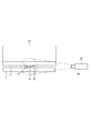
- FIG. 1 is a schematic configuration diagram of the coating device 10.
- the coating device 10 is a device for applying the coating liquid R to the substrate 7.
- the coating device 10 includes a coating device (also referred to as a slit die) 12, a moving means 14, a device base 16, a supply means 18, and a control device 20.
- the substrate 7 of the present disclosure is a circular plate-shaped member, and is a semiconductor wafer (silicon wafer).
- the device base 16 has a stage 22 that holds the substrate 7.
- the control device 20 is composed of a computer device.
- the applicator 12 is composed of members that are long in the width direction (direction orthogonal to the paper surface in FIG. 1).
- the applicator 12 has a reservoir 24 formed by an enlarged space and accumulating the coating liquid R, and a slit (slit-shaped flow path) 26 connected to the reservoir 24.
- the slit 26 opens at the tip end surface 11 of the applicator 12, and the opening 28 of the slit 26 serves as a discharge port for the coating liquid R. That is, the coating liquid R of the reservoir 24 is discharged from the opening 28 through the slit 26.
- the reservoir 24, the slit 26, and the opening 28 are provided long along the width direction of the applicator 12.
- the coating device 12 can be located above the substrate 7, and the coating liquid R is discharged downward from the opening 28. Therefore, the upper surface side of the substrate 7 becomes the surface to be coated 8 to which the coating liquid R is applied.
- the applicator 12 has a pressure sensor 30.
- the pressure sensor 30 measures the pressure of the coating liquid R in the coating device 12 (reservoir 24). The measurement result of the pressure sensor 30 is given to the control device 20.
- the moving means 14 has a moving body 32 that can move in the direction intersecting the width direction of the applicator 12 (direction orthogonal to each other in the present disclosure), that is, in the left-right direction in FIG. 1, and a linear actuator 34 that moves the moving body 32. And have.
- the applicator 12 is mounted on the moving body 32.
- the moving means 14 moves the coating device 12 with respect to the substrate 7 while keeping the gap K between the surface to be coated 8 and the tip surface 11 of the coating device 12 constant.
- the moving means 14 of the present disclosure has a configuration in which the coating device 12 is moved with respect to the substrate 7 in the fixed state, but the moving means 14 has a configuration in which the coating device 12 and the substrate 7 are relatively moved.
- the stage 22 (board 7) may be moved with respect to the fixed coater 12.
- the supply means 18 has a first supply mechanism 40 having a tank 36 and a pressure regulator 38, and a second supply mechanism 44 having a metering pump 42.
- the metering pump 42 operates under the control of the control device 20, and can supply a predetermined flow rate of the coating liquid R to the coating device 12 (reservoir 24) through the pipe 46.
- the tank 36 stores the coating liquid R and is connected to the coating device 12 (reservoir portion 14) through the pipe 48.
- the tank 36 is provided at a position higher than the applicator 12 (reservoir 24).
- the pipe 48 is provided with an open / close switching valve 50. With the valve 50 open, the coating liquid R can flow between the tank 36 and the coating device 12 (reservoir 24).
- the replenishment is performed by the metering pump 42 (second supply mechanism 44).
- the coating liquid R when the coating liquid R is discharged from the coating device 12 and consumed, the coating liquid R can be replenished from the tank 36 to the coating device 12.
- the replenishment may be performed by the first supply mechanism 40. That is, the second supply mechanism 44 may be omitted.
- the pressure regulator 38 is composed of a regulator controlled by the control device 20 and changes the pressure of the coating liquid R in the tank 36 (adjusts the pressure). Since the tank 36 and the applicator 12 are connected through the pipe 48, when the pressure of the coating liquid R in the tank 36 is adjusted, the pressure of the coating liquid R in the applicator 12 (reservoir 24) becomes a predetermined value. Adjusted (ie controlled).
- the pressure regulator 38 has a mechanism (vacuum pump or the like) for sucking the inside of the tank 36, the inside of the tank 36 is sucked by the pressure regulator 38, and the tank 36 is coated by the pressure regulator 38. The pressure (gauge pressure) acting on the liquid R is adjusted to a negative pressure.
- the pressure (gauge pressure) of the coating liquid R in the coating device 12 can become a negative pressure.
- the pressure regulator 38 adjusts the pressure of the coating liquid R stored in the tank 36 so that the pressure of the coating liquid R in the coating device 12 is maintained at a predetermined value (negative pressure). This adjustment is performed by controlling the control device 20 based on the detection result of the pressure sensor 30.
- a vacuum pump different from the pressure regulator 38 may be provided as a mechanism for sucking the inside of the tank 36.
- the coating device 10 can perform capillary coating on the substrate 7.
- the coating method of the present disclosure is a downward capillary coating method. That is, the tip surface 11 of the applicator 12 and the surface to be coated 8 are brought close to each other.
- the slit 26 is open on the tip surface 11.
- a liquid pool Ra (also referred to as “bead Ra”) of the coating liquid R is formed in the gap K between the tip surface 11 and the surface to be coated 8. Will be done.
- the valve 51 is closed and the supply of the coating liquid R to the coating device 12 is temporarily stopped.
- the pressure of the coating liquid R in the coating device 12 is adjusted to a predetermined value of negative pressure (relative to atmospheric pressure), and the coating device 12 is moved with respect to the substrate 7.
- the coating liquid R is filled in the gap K and is drawn out from the coating device 12, so that the coating liquid R is continuously applied to the substrate 7.
- the consumed amount of coating liquid R is replenished to the coating device 12 by the first supply mechanism 40 or the second supply mechanism 44.
- the coating liquid R is applied by the capillary phenomenon (surface tension) between the tip surface 11 and the surface to be coated 8.
- the coating liquid R is applied to the substrate 7 by being pulled out from the vessel 12.
- the moving direction of the applicator 12 during the coating operation is from right to left, and the direction from right to left is the “base moving direction”.
- the right side of FIG. 1 is the upstream side in the mouthpiece moving direction, and the left side is the downstream side.
- the coating liquid R is applied to the surface to be coated 8.
- a small amount of the coating liquid R is discharged from the coating device 12 and the coating liquid R is adhered to the surface to be coated 8 (this). Is referred to as "liquiding operation").
- the position where the coating liquid R is adhered (hereinafter, this position is referred to as a “liquid landing portion”) is the edge portion on the most upstream side of the surface to be coated 8.
- the liquid landing portion 9 is a point-like region narrow in the width direction.
- a two-dot chain line (virtual line) is shown for explaining the liquid-immersion portion 9, and the upper surface of the range between the two two-dot chain lines on the substrate 7 is the liquid-adhesive portion 9.
- the coating device 10 further includes a camera (CCD video camera) 52 as a detection device.
- the camera 52 has an image sensor 53 as a light receiving portion directed to a gap K between the tip surface 11 of the coater 12 and the liquid landing portion 9 of the surface to be coated 8.
- the image (photographed image) captured by the image sensor 53 is input to the control device 20 (see FIG. 1).
- the camera 52 is installed on the upstream side in the mouthpiece moving direction with respect to the gap K, and photographs the gap K from the upstream side.
- the camera 52 may be provided on the downstream side. Even in this case, the image pickup target is the same, and the image pickup element 53 and the lens are directed to the gap K. In this way, when the camera 52 captures the gap K from the upstream side (or downstream side) in the movement direction of the base, it is possible to capture the entire range to be liquided.
- the control device 20 detects that the coating liquid R has adhered to the surface to be coated 8 by using the captured image acquired by the camera 52. This detection is referred to as "liquid application completion detection". Further, the control device 20 detects that the coating liquid R has started to be discharged from the tip surface 11 (opening 28) of the coating device 12 by using the captured image acquired by the camera 52. The control device 20 can perform the resetting process of the pressure in the coating device 12 based on the detection of the discharge start. Further, the control device 20 can detect the abnormality of the coating device 10 by using the captured image acquired by the camera 52. Hereinafter, specific examples of each of the processes performed by the control device 20 will be described. Further, as will be described later, the detection of the completion of liquid application, the pressure resetting process, and the detection of the abnormality of the coating device 10 may be performed by a detection device (transmission type sensor or reflection type sensor) other than the camera 52. can.
- a detection device transmission type sensor or reflection type sensor
- the control device 20 has a detection processing unit 54 and an operation control unit 56 as functional units realized by the processing performed by the processor.
- the detection processing unit 54 detects the coating liquid R in the gap K based on the detection signal (photographed image) from the detection device such as the camera 52. Therefore, when the detection device is the camera 52, the detection processing unit 54 has an image processing function (image processing engine).
- the operation control unit 56 executes the next operation for coating based on the detection result of the detection processing unit 54.
- An example of the "next operation” is a coating operation in which the coating liquid R is discharged from the opening 28 of the coating device 12 while relatively moving the coating device 12 and the surface to be coated 8.
- FIG. 3 is an explanatory diagram showing an image P captured by the camera 52.
- the imaging is continuously performed from the start of the liquidation operation, that is, from the start of the operation of the metering pump 42 (or the start of supply of the coating liquid R from the tank 36) to the completion of the liquidation.
- the photographed image P is continuously obtained, and the control device 20 acquires the photographed image P.
- the detection processing unit 54 of the control device 20 may target all areas of each captured image P for image processing, but in the present disclosure, a part of the captured image P is targeted for image processing.
- the range of the target of image processing is referred to as the processing target Q (see FIG. 3).
- the processing target Q is a range between two virtual lines (dashed-dotted line) in the gap K.
- the virtual line on the left side of FIG. 3 passes through one end of the liquid landing portion 9 and is orthogonal to the surface to be coated 8, and the virtual line on the right side passes through the other end of the liquid landing portion 9 and is coated. It is a line orthogonal to the surface 8.
- the processing target Q is between the tip surface 11 of the applicator 12 and the surface to be coated 8, and is the liquid landing portion 9 of the surface to be coated 8 and the liquid landing portion in the tip surface 11 of the applicator 12. It is a range between the position facing the 9 and the opposite position.
- the processing target Q may be a wider range or a narrower range than between the two virtual lines. That is, the processing target Q may be a region in the gap K between at least a part of the liquid landing portion 9 and at least a part of the opposite position.
- the detection processing unit 54 performs image processing on the image (image data) of the processing target Q.
- image processing in order to distinguish the region of the coating liquid R from the region other than the coating liquid R (that is, the background), a process of binarizing the image of the processing target Q (the image is divided into white and black). Processing to convert into two stages) is included. That is, in the processing target Q, for example, the range of the image of the coating liquid R is set to "black", and the region of the image other than the coating liquid R is set to "white”. In FIG. 3 (FIG. 5), the image portion of the coating liquid R is a cross hatch. In the digital processing (the binarizing process) performed by the detection processing unit 54, for example, "black” is treated as "1" and "white” is treated as "0".
- the detection processing unit 54 determines that black is 100%, which is the threshold value, as a result of binarizing the image of the processing target Q, it detects that the liquidation is completed at the timing of this determination, and the liquid landing is completed. Generate information.
- the operation control unit 56 acquires the generated liquid landing completion information. Then, the operation control unit 56 stops the supply of the coating liquid R from the metering pump 42 or the tank 36, and ends the liquiding operation. Then, as the next operation for coating, the operation control unit 56 puts the coating liquid R in the coating device 12 into a negative pressure state in which the pressure regulator 38 sets the pressure to a predetermined pressure, and the moving means 14 presses the coated surface 8 with respect to the surface to be coated 8. The movement of the applicator 12 is started.
- the predetermined pressure is set based on the measured value of the pressure sensor 30.
- the proportion of the image of the coating liquid R in the gap K changes as compared with immediately before that. Therefore, it is possible to detect that the coating liquid R has landed on the surface to be coated 8 based on the ratio of the range occupied by the image of the coating liquid R in the treatment target Q.
- the detection of the liquid landing may be based on the ratio of the range occupied by the image other than the coating liquid R in the image of the processing target Q, or the image of the coating liquid R in the image of the processing target Q. It may be based on both the ratio of the range occupied by the coating liquid R and the ratio of the range occupied by the image other than the coating liquid R.
- the detection processing unit 54 processes the captured image P of the camera 52 based on at least one of the ratio of the image of the coating liquid R in the gap K and the ratio of the image other than the coating liquid R. Then, it is detected that the coating liquid R in the gap K has adhered to the surface to be coated 8.
- the camera 52 should at least capture a range of the tip surface 11 of the applicator 12 including the position facing the liquid landing portion 9. Just do it. Further, the detection processing unit 54 may target the entire region of the captured image P (see FIG. 3) as the processing target, or may target a part of the captured image P as the image processing target. For the pressure resetting process, the processing target Q may be at least a range including a portion of the tip surface 11 of the applicator 12 facing the liquid landing portion 9.
- the detection processing unit 54 performs image processing on the image (image data) of the processing target Q. Similar to the case of the liquid application completion detection, the process of binarizing the image of the processing target Q (the process of converting the image into two stages of white and black) is performed. That is, in the processing target Q, for example, the range of the image of the coating liquid R is "black (" 1 "in the digital processing)", and the region of the image other than the coating liquid R is “white (" 0 "in the digital processing)”. And.
- the operation control unit 56 acquires the discharge start information. Then, the operation control unit 56 sets the pressure in the coater 12 (the pressure of the reservoir 24) at the timing when it is determined that the ratio of “black” exceeds the threshold value as the reference pressure.
- the pressure sensor 30 measures the pressure inside the applicator 12 every moment. After that, in the coating operation performed, the set reference pressure is used as a reference. By setting (resetting) the reference pressure in this way, it is possible to correct the time-dependent variation in pressure measurement by the pressure sensor 30. By setting the reference pressure, a boundary (boundary of pressure in the coating device 12) at which the coating liquid R is discharged / not discharged from the coating device 12 is set. Therefore, for example, it is possible to suppress a change in the discharge amount of the coating liquid R due to a change in the atmospheric pressure around the coating device 12.
- the detection of the discharge start is the range occupied by the image other than the coating liquid R in the image of the processing target Q. It may be based on the ratio, or may be based on both the ratio of the range occupied by the image of the coating liquid R and the ratio of the range occupied by the image other than the coating liquid R in the image of the processing target Q.
- the detection processing unit 54 processes the captured image P of the camera to obtain at least one of the ratio of the image of the coating liquid R in the gap K and the ratio of the image other than the coating liquid R.
- the detection processing unit 54 detects that the discharge of the coating liquid R has been started from the coating device 12 based on the obtained ratio, and generates the discharge start information.
- the operation control unit 56 sets the pressure measurement value (measured value by the pressure sensor 30) in the coater 12 at the timing when the discharge of the coating liquid R is started for the coating operation. Set (reset) to the reference pressure of.
- the above resetting process may be performed before a new substrate 7 is carried into the stage 22 and the coating operation on the substrate 7 is started, but it is performed intermittently for each of a plurality of coating operations. May be good.
- the detection device having the light receiving portion directed to the gap K is the camera 52 has been described.
- the detection device may have other configurations.
- the detection device may be a transmissive sensor or a reflective sensor.
- a case where the detection device is a transmission type sensor will be described.
- the transmissive sensor 58 has a light emitting unit 60 having a light emitting element 60a that emits light, and a light receiving unit 62.
- the light receiving unit 62 has a light receiving element 62a that receives the light emitted by the light emitting element 60a.
- the light receiving unit 62 outputs the light receiving signal to the control device 20.
- the output of the light receiving signal is stopped.
- the light emitting unit 60 and the light receiving unit 62 are provided separately on the upstream side and the downstream side in the mouthpiece moving direction with a gap K between the coating device 12 and the surface to be coated 8 interposed therebetween.
- a light receiving unit 62 is provided on the upstream side, and a light emitting unit 60 is provided on the downstream side.
- the light emitting unit 60 emits light at least toward the vicinity of the surface to be coated 8 in the gap K, and the light receiving unit 62 can receive this light.
- the light emitting unit 60 emits light toward a region including the gap K from the surface to be coated 8 to the tip surface 11 of the coater 12.
- the light receiving unit 62 has a plurality of light receiving elements 62a.
- the light receiving signal (light receiving signal level) is changed and output according to the range of light received by the light receiving unit 62. That is, the light receiving signal (light receiving signal level) differs depending on whether the light is received by the entire light receiving unit 62 or a part of the light receiving unit 62.
- the liquid application completion detection using the transmissive sensor 58 having the above configuration is performed as follows.
- the light receiving unit 62 detects the light from the light emitting unit 60.
- the coating liquid R starts to be discharged from the coating device 12 into the gap K, a part of the gap K is blocked by the coating liquid R.
- the light from the light emitting unit 60 passing through the gap K is reduced, but the light receiving unit 62 detects a part of the light until the liquidation is completed.
- the light receiving signal changes depending on whether the coating liquid R has not been discharged or has started to be discharged.
- the detection processing unit 54 of the control device 20 is still liquidated while the light receiving signal is being acquired. Judge that it is not completed.
- the coating liquid R discharged from the coating device 12 into the gap K reaches the surface to be coated 8 (that is, when the liquid application is completed)
- the light from the light emitting unit 60 is emitted by the coating liquid R. It is blocked and the light receiving unit 62 does not detect light. Then, the light receiving signal is not output from the light receiving unit 62, and the detection processing unit 54 does not acquire the light receiving signal. Therefore, the detection processing unit 54 detects that the liquidation has been completed at this timing, and generates the liquidation completion information.
- the control device 20 detects the completion of liquid application.
- the operation control unit 56 acquires the generated liquid landing completion information.
- the operation control unit 56 stops the supply of the coating liquid R from the metering pump 42 or the tank 36. Then, as the next operation for coating, the operation control unit 56 puts the coating liquid R in the coating device 12 into a negative pressure state in which the pressure regulator 38 sets the pressure to a predetermined pressure, and the moving means 14 presses the coated surface 8 with respect to the surface to be coated 8. The movement of the applicator 12 is started.
- the predetermined pressure is set based on the measured value of the pressure sensor 30.
- a transmissive sensor 58 is used as the detection device.
- the transmissive sensor 58 has a light receiving unit 62 directed to the gap K and a light emitting unit 60 that emits light toward the light receiving unit 62 through the gap K.
- the light receiving unit 62 can output the light receiving signal to the detection processing unit 54.
- the coating liquid R discharged from the coating device 12 adheres to the surface to be coated 8 (see FIG. 7)
- the light of the light emitting unit 60 is blocked by the coating liquid R.
- the light receiving unit 62 is configured so that the light receiving signal changes when the light from the light emitting unit 60 is blocked in the gap K.
- this change includes a case where the received light signal is changed from the output state to the non-output state. That is, when the light from the light emitting unit 60 is blocked in the gap K, the light receiving signal from the light receiving unit 62 is interrupted. As a result, the detection processing unit 54 can detect that the liquid application to the surface to be coated 8 has been completed. The detection processing unit 54 detects that the coating liquid R in the gap K has adhered to the surface to be coated 8 based on the change in the light receiving signal.
- the light receiving unit 62 may have a configuration other than that described above, and the light receiving element 62a may be one. Even in this case, the light receiving unit 62 can receive the light until the light from the light emitting unit 60 is blocked by the coating liquid R. However, when the coating liquid R reaches the surface to be coated 8, the light from the light emitting unit 60 is blocked by the coating liquid R, and the light receiving unit 62 does not detect the light. Then, the detection processing unit 54 can detect that the liquidation is completed at the timing when the received light signal is not acquired.
- the configuration of the transmissive sensor 58 is as described above.
- the light receiving unit 62 receives the light of the light emitting unit 60, the light receiving unit 62 can output the light receiving signal to the detection processing unit 54.
- the light receiving unit 62 is configured so that the light receiving signal changes when the light of the light emitting unit 60 is blocked at least on the tip surface 11 side of the coater 12 in the gap K.
- the pressure resetting process using the transmission type sensor 58 is performed as follows.
- the light receiving unit 62 detects the light from the light emitting unit 60.
- the light receiving signal is output to the control device 20.
- the coating liquid R starts to be discharged from the coating device 12 into the gap K, a part of the gap K is blocked by the coating liquid R. Therefore, the light from the light emitting unit 60 passing through the gap K is reduced.
- the detection processing unit 54 determines the change in the received light signal.
- the detection processing unit 54 determines that the light receiving signal has changed, the detection processing unit 54 generates discharge start information indicating that the discharge of the coating liquid R has been started from the coating device 12.
- the operation control unit 56 acquires the discharge start information. Then, as described above, the operation control unit 56 sets the pressure in the coater 12 (the pressure of the reservoir 24) at the timing when it is determined that the received light signal has changed as the reference pressure.
- the pressure sensor 30 measures the pressure inside the applicator 12 every moment. After that, in the coating operation performed, the set reference pressure is used as a reference. By setting (resetting) the reference pressure in this way, it is possible to correct the time-dependent variation in pressure measurement by the pressure sensor 30. By setting the reference pressure, a boundary (boundary of pressure in the coating device 12) at which the coating liquid R is discharged / not discharged from the coating device 12 is set. Therefore, for example, it is possible to suppress a change in the discharge amount of the coating liquid R due to a change in the atmospheric pressure around the coating device 12.
- the detection processing unit 54 can detect that the discharge of the coating liquid has been started from the coating device 12 based on the change in the received light signal, and can generate the discharge start information. Then, when the discharge start information is generated, the operation control unit 56 determines the pressure measurement value (pressure sensor) in the coater 12 at the timing when the received light signal changes, that is, at the timing when the discharge of the coating liquid is started. The value measured by 30) is set (reset) to the reference pressure for the coating operation.
- the above resetting process may be performed before a new substrate 7 is carried into the stage 22 and the coating operation on the substrate 7 is started, but it is performed intermittently for each of a plurality of coating operations. May be good.
- the reflection type sensor 64 has a light emitting unit 66 having a light emitting element 66a that emits light, and a light receiving unit 68.
- the light receiving unit 68 has a light receiving element 68a that receives the reflected light of the light from the light emitting element 66a.
- the light receiving unit 68 outputs the light receiving signal to the control device 20. If there is no object and there is no reflection of light from the light emitting unit 66, the light receiving unit 68 cannot receive light and no light receiving signal is output.
- the light emitting unit 66 emits light toward the gap K.
- the light receiving unit 68 can detect the light from the light emitting unit 66 and reflected by the coating liquid R (see FIG. 9) existing in the gap K.
- the light emitting unit 66 and the light receiving unit 68 are provided on the same side toward the gap K. That is, the light emitting unit 66 and the light receiving unit 68 are provided on either one of the upstream side and the downstream side in the base moving direction with the gap K as a reference.
- a light emitting unit 66 and a light receiving unit 68 are provided on the upstream side in the direction of movement of the base.
- the light emitting unit 66 emits light toward the vicinity of the surface to be coated 8 at least in the gap K, and the light receiving unit 68 can receive the light reflected in the vicinity of the surface 8 to be coated at least in the gap K. ..
- light is emitted toward a region including the gap K from the surface to be coated 8 to the tip surface 11 of the coater 12.
- the light receiving unit 68 has a plurality of light receiving elements 68a, and outputs a light receiving signal according to the range of light received by the light receiving unit 68. That is, the light receiving signal (light receiving signal level) differs depending on whether the light is received by the entire light receiving unit 68 or a part of the light receiving unit 68.
- the coating liquid R In the state where the coating liquid R is not discharged from the coating device 12 (see FIG. 8), since the coating liquid R does not exist in the gap K, the reflection of light by the coating liquid R is zero. Therefore, the light receiving signal is not output from the light receiving unit 68.
- the coating liquid R is discharged from the coating device 12, since the coating liquid R exists in the gap K, light is reflected by the coating liquid R.
- the light receiving unit 68 can detect the reflected light.
- the light receiving unit 68 outputs the light receiving signal to the control device 20, and the control device 20 acquires the light receiving signal.
- the coating liquid R discharged from the coating device 12 reaches the surface to be coated 8 (see FIG. 9)
- the coating liquid R exists in the gap K
- light is reflected by the coating liquid R.
- the light receiving unit 68 can detect the reflected light.
- the light receiving unit 68 outputs the light receiving signal to the control device 20, and the detection processing unit 54 acquires the light receiving signal.
- the light receiving signal (light receiving signal level) is different.
- the liquid application completion detection using the reflection type sensor 64 having the above configuration is performed as follows.
- the light receiving unit 68 cannot detect the light (reflected light) from the light emitting unit 66.
- the light receiving unit 68 detects the reflected light from the coating liquid R.
- the light receiving signal is output to the control device 20.
- the light receiving unit 68 detects the reflected light from the coating liquid R and outputs the light receiving signal to the control device 20 even in this case. ..
- the light receiving unit 68 changes the light receiving signal and outputs it according to the received light range. Therefore, the detection processing unit 54 that has acquired the received light signal compares the received signal (the level of the received signal) with a preset threshold value. When the received light signal exceeds the threshold value, it is detected that the liquidation is completed, and the liquidation completion information is generated.
- the threshold value is the level of the light receiving signal output when the light receiving unit 68 receives the reflected light in the state immediately before the liquidation of the coating liquid R is completed.
- the detection processing unit 54 determines that the light receiving signal exceeds the threshold value, it detects that the liquidation is completed at that timing, and the liquidation completion information is generated and output. As described above, the control device 20 detects the completion of liquid application.
- the operation control unit 56 acquires the generated liquid landing completion information. Then, the operation control unit 56 stops the supply of the coating liquid R from the metering pump 42 or the tank 36. Then, as the next operation for coating, the operation control unit 56 puts the coating liquid R in the coating device 12 into a negative pressure state in which the pressure regulator 38 sets the pressure to a predetermined pressure, and the moving means 14 presses the coated surface 8 with respect to the surface to be coated 8. The movement of the applicator 12 is started.
- the predetermined pressure is set based on the measured value of the pressure sensor 30.
- the reflection type sensor 64 is used as the detection device.
- the reflection type sensor 64 has a light receiving unit 62 directed to the gap K and a light emitting unit 66 that emits light toward the gap K.
- the light receiving unit 68 receives the light emitted by the light emitting unit 66 and reflected by the coating liquid R in the gap K
- the light receiving unit 68 can output the light receiving signal to the detection processing unit 54.
- the coating liquid R discharged from the coating device 12 adheres to the surface to be coated 8
- the light of the light emitting unit 66 is reflected by the coating liquid R, and the light receiving unit 68 receives the reflected light and detects the light receiving signal. It can be output to 54. Therefore, the detection processing unit 54 detects that the coating liquid R in the gap K has adhered to the surface to be coated 8 based on the light receiving signal.
- the configuration of the reflection type sensor 64 is as described above.
- the light receiving unit 62 receives the light emitted by the light emitting unit 60 and reflected by the coating liquid R in the gap K, the light receiving unit 62 can output the light receiving signal to the detection processing unit 54.
- the light receiving unit 62 is configured such that the light of the light emitting unit 60 is reflected at least on the tip surface 11 side of the coater 12 in the gap K, and when the light is received, the light receiving signal changes.
- the pressure resetting process performed using the reflection type sensor 64 is performed as follows.
- the light receiving unit 68 does not detect the light (reflected light) from the light emitting unit 66.
- the light receiving unit 68 detects the reflected light from the coating liquid R.
- the light receiving signal is output to the control device 20.
- the detection processing unit 54 acquires the light receiving signal, it detects that the discharge of the coating liquid R has started from the coating device 12, generates the discharge start information, and outputs it.
- the detection processing unit 54 can detect that the coating liquid R has started to be discharged from the coating device 12 based on the received light signal, and can generate the discharge start information. Then, when the discharge start information is generated, the operation control unit 56 acquires the light receiving signal, that is, the pressure measurement value (pressure sensor 30) in the coater 12 at the timing when the discharge of the coating liquid R is started. (Measured value by) is set (reset) to the reference pressure for the coating operation.
- the coating liquid R is applied to the coating device by setting the reference pressure as described above.
- the boundary between discharge / non-discharge from 12 (the boundary of pressure in the coater 12) is set. With this setting, it is possible to correct the time-dependent variation in pressure measurement, suppress the change in the discharge amount of the coating liquid due to the change in atmospheric pressure, and the like.
- the resetting process may be performed before each new substrate 7 is carried into the stage 22 and the coating operation on the substrate 7 is started, but the resetting process is performed intermittently for each of a plurality of coating operations. May be good.
- the operation control unit 56 of the control device 20 is required from the start of the liquid application operation, that is, the start of the operation of the metering pump 42 (or the start of supply of the coating liquid R from the tank 36) to the timing (instantaneous). Count the time you spent.
- the operation control unit 56 counts the time and compares the count value with a preset threshold value. This count value is progress information regarding the operation of the coating device 10 from the state in which the coating liquid R does not exist in the gap K to the state in which the coating liquid R exists in the gap K. When the count value exceeds the threshold value, the abnormality information indicating that an abnormality may have occurred, that is, the abnormality information indicating that air may be mixed in the coater 12 is provided. It is generated by the operation control unit 56.
- the operation control unit 56 executes the operation of the air vent for discharging the air in the coater 12 to the outside. For example, although not shown, the valve connected to the reservoir 24 of the coating device 12 is opened to discharge air together with the coating liquid R to the outside. After that, the operation control unit 56 returns the coating device 10 to the coating operation.
- the operation control unit 56 provides progress information regarding the operation of the coating device 10 from the state in which the coating liquid R does not exist in the gap K to the state in which the coating liquid R exists in the gap K. get. Then, the motion control unit 56 compares the value indicated by the progress information with the threshold value. Based on this comparison, as the next operation for coating, the abnormality of the coating device 10 that should be confirmed before the coating operation is detected. In this way, an abnormality in the coating device 10 (mixture of air in the coating device 12) is detected.
- the progress information may be other than the count value of the operating time of the metering pump 42 or the like, may be the flow rate of the coating liquid R supplied to the coating device 12, or may be the operating stroke of the metering pump 42. However, at least one of these pieces of information may be used.
- the coating device 10 of each form includes the coating device 12 in which the slit 26 opens at the tip surface 11.
- the coating liquid R is applied to the surface to be coated 8 by discharging the coating liquid R from the opening 28 of the coating device 12 while the coating device 12 and the surface to be coated 8 are relatively moving.
- the coating device 10 includes a detection device including a camera 52 and the like, a detection processing unit 54, and an operation control unit 56.
- the detection device has a light receiving portion directed to a gap K between the tip surface 11 and the surface to be coated 8.
- the detection processing unit 54 detects the coating liquid R in the gap K based on the detection signal from the detection device.
- the operation control unit 56 executes the next operation for coating based on the detection result of the detection processing unit 54.
- the coating method executed by the coating device 10 is as follows. That is, it is a method of applying the coating liquid to the surface to be coated 8 by discharging the coating liquid R from the opening 28 of the coating device 12 while the coating device 12 and the surface to be coated 8 are relatively moving.
- the light receiving portion of the detection device is directed to the gap K between the tip surface 11 of the coating device 12 and the surface to be coated 8, and the coating liquid R in the gap K is detected based on the detection signal from the detection device. Based on the result of this detection, the next action for coating is performed.
- the coating device 10 and the coating method it is possible to detect whether or not the coating liquid R is present in the gap K by capturing the image or shadow of the coating liquid R by the light receiving portion directed to the gap K. Is possible. Therefore, as the next operation for coating, the coating operation for starting the relative movement, the pressure resetting process for setting the pressure in the coating device 12 for this coating operation, and the coating quality are affected. It is possible to shift to an operation of detecting an abnormality in the coating device 10 which may give a problem.
- a light source (light emitting unit) is provided even when the detection device is the camera 52.
- the coating device 10 in which a detection device such as a camera 52 is used as in each of the above forms can be applied to other coating methods in addition to capillary coating.
- a coating method for example, a coating method may be performed in which the coating liquid is forcibly discharged from the coating device by supplying the coating liquid to the coating device with a metering pump or the like.
- the substrate 7 is circular
- it may be rectangular
- Liquid landing part 10 Coating device 11: Tip surface 12: Coating device 26: Slit 28: Aperture 52: Camera (detection device) 53: Image sensor (light receiving part) 54: Detection processing unit 56: Operation control unit 58: Transmissive sensor (detection device) 60: Light emitting part 62: Light receiving part 64: Reflective type sensor (detector) 66: Light emitting part 68: Light receiving part K: Gap R: Coating liquid
Landscapes
- Coating Apparatus (AREA)
- Application Of Or Painting With Fluid Materials (AREA)
Abstract
先端面のスリットが開口する塗布器を備え、塗布器と被塗布面とが相対的に移動しながら塗布器の開口から塗布液が吐出されることで被塗布面に塗布液を塗布する塗布装置の塗布動作において、塗布器と被塗布面との間の隙間に塗布液が存在するか否かを検出し、この検出に基づいて、塗布のための次の動作に移行させる。具体的には、先端面と被塗布面との間の隙間に向けられた受光部を有する検出装置と、前記検出装置からの検出信号に基づいて隙間の塗布液を検出する検出処理部と、検出処理部の検出結果に基づいて塗布のための次の動作を実行する動作制御部とを備えるように構成する。
Description
本発明は、塗布装置及び塗布方法に関する。
半導体の製造工程では、半導体ウエハ(シリコンウエハ)にフォトレジスト液が塗布される。この塗布の方法として、スピンコートが知られているが、近年、フォトレジスト液の利用効率向上の観点から、塗布器によるスリットコートが提案されている。特許文献1には、前記塗布器を備えた塗布装置が開示されている。
特許文献1に開示されている塗布装置は、いわゆるキャピラリ塗布を行う装置である。塗布装置が備える塗布器には、先端面で開口するスリットが設けられている。キャピラリ塗布は、塗布器と被塗布面(基板)とを相対移動させると、塗布液が塗布器の先端面と被塗布面との隙間に満たされることでスリットから引き出されて塗布を行う方法である。
前記のようなキャピラリ塗布であっても、それ以外の塗布(例えば、塗布液を塗布器に供給することで塗布液を強制的に吐出させる塗布)の方法であっても、塗布器と被塗布面とを相対移動させながら被塗布面に対して塗布液を吐出させる塗布動作の開始前に、塗布器から吐出させた塗布液を被塗布面の一領域(端部)に付着させる「液付け動作」が行われる。
例えば、キャピラリ塗布の場合、先ず、塗布器内の塗布液の圧力を、大気圧に対して負圧の状態とし、被塗布面の一領域(端部)の直上に塗布器を位置させる。次に、定量ポンプが塗布液を塗布器に供給する。これにより、塗布器から塗布液が吐出され、その塗布液が被塗布面の前記一領域に付着する(液付け完了)。塗布液が被塗布面に付着すると、定量ポンプは停止する。
定量ポンプの停止のタイミングは、塗布器内の塗布液の圧力を圧力センサによって監視することで決定できる。具体的に説明する。圧力センサは、塗布器のスリットと繋がる塗布器内の拡大空間における塗布液の圧力を検出する。キャピラリ塗布の場合、前記のとおり、液付け動作の際、塗布器内の塗布液の圧力は、始め負圧であるが、定量ポンプが塗布液を塗布器に供給するとしだいに正圧側へ変化する。そして、塗布器から吐出させた塗布液が被塗布面に付着すると、その塗布液の表面張力によって更に塗布液を塗布器から引き出す力が生じる。これにより、塗布器内が負圧側へ変化する。そこで、この負圧側への変化が圧力センサによって検出されることで、液付け完了のタイミングを知ることができ、このタイミングで定量ポンプを停止させればよい。
しかし、塗布液が被塗布面に液付けされ、塗布器内が負圧側へ変化しても、その圧力変化の伝播が圧力センサへ到達するまでに遅延したり、また、圧力変化が小さいと圧力センサの能力によっては、これを捉えきれずに検知エラーが発生したりするかもしれない。被塗布面への液付けの完了が検出されないと、塗布のための次の動作に移行することができない。なお、前記のような課題は、塗布液の粘度が低い場合でも発生するが、粘度が高い場合により顕著に発生することが考えられる。
そこで、本発明の目的は、新たな技術手段により、塗布器と被塗布面との間の隙間に塗布液が存在するか否かを検出し、この検出に基づいて、塗布のための次の動作に移行させることにある。
本発明は、先端面でスリットが開口する塗布器を備え、当該塗布器と被塗布面とが相対的に移動しながら前記塗布器の開口から塗布液が吐出されることで当該被塗布面に塗布液を塗布する装置であって、前記先端面と前記被塗布面との間の隙間に向けられた受光部を有する検出装置と、前記検出装置からの検出信号に基づいて前記隙間の塗布液を検出する検出処理部と、前記検出処理部の検出結果に基づいて塗布のための次の動作を実行する動作制御部と、を備える。
この塗布装置によれば、塗布器の先端面と被塗布面との間の隙間に向けられた受光部により、塗布液を捉えることで、前記隙間に塗布液が存在するか否かを検出することが可能となる。このため、塗布のための次の動作として、例えば、前記相対的な移動を開始させる塗布動作、この塗布動作のために塗布器内の圧力を設定(再設定)する動作、及び、塗布品質に影響を与える可能性のある塗布装置における異常を検出する動作等に、移行することができる。
また、前記塗布装置は、次のように構成されていてもよい。前記検出装置は、前記受光部として撮像素子を有するカメラであり、前記検出処理部は、前記カメラの撮影画像を画像処理し、前記隙間における塗布液の像の占める割合と塗布液以外の像の占める割合との内の少なくとも一方の割合に基づいて、前記隙間の塗布液が前記被塗布面に付着したことを検出する。
この場合、検出装置としてカメラが用いられる。塗布器から前記隙間に吐出された塗布液が被塗布面に付着すると、その直前と比べて、前記隙間における塗布液の像の占める割合及び/又は塗布液以外の像の占める割合が変化する。この変化により、検出処理部は、被塗布面への液付けが完了したことの検出が可能となる。液付けの完了が検出されると、液付け動作を終了し、動作制御部は、次の動作として、例えば塗布器と被塗布面との相対移動を開始させる。
または、前記塗布装置は、次のように構成されていてもよい。前記検出装置は、前記隙間を経て前記受光部に向かう光を発する発光部を更に有していて、前記受光部は、前記発光部の光を受光すると受光信号を前記検出処理部へ出力可能であって、当該光が前記隙間において遮断されると当該受光信号が変化する構成であり、前記検出処理部は、前記受光信号の変化に基づいて、前記隙間の塗布液が前記被塗布面に付着したことを検出する。
この場合、検出装置として透過型のセンサが用いられる。塗布器から前記隙間に吐出された塗布液が被塗布面に付着すると、この塗布液によって発光部の光が遮断され、受光部からの受光信号が変化する。なお、この変化には、受光信号が出力されていた状態から、出力されない状態に変化する場合も含まれる。この変化により、検出処理部は、被塗布面への液付けが完了したことの検出が可能となる。液付けの完了が検出されると、液付け動作を終了し、前記動作制御部は、次の動作として、例えば塗布器と被塗布面との相対移動を開始させる。
または、前記塗布装置は、次のように構成されていてもよい。前記検出装置は、前記隙間に向かって光を発する発光部を更に有していて、前記受光部は、前記発光部が発し前記隙間の塗布液で反射した光を受光すると受光信号を前記検出処理部へ出力可能であり、前記検出処理部は、前記受光信号に基づいて、前記隙間の塗布液が前記被塗布面に付着したことを検出する。
この場合、検出装置として反射型のセンサが用いられる。塗布器から前記隙間に吐出された塗布液が被塗布面に付着すると、この塗布液によって発光部の光が反射され、受光部はこの反射した光を受光し受光信号を検出処理部へ出力する。これにより、検出処理部は、被塗布面への液付けが完了したことの検出が可能となる。液付けの完了が検出されると、液付け動作を終了し、前記動作制御部は、次の動作として、例えば塗布器と被塗布面との相対移動を開始させる。
また、前記塗布装置は、更に次のように構成されていてもよい。前記検出装置は、前記受光部として撮像素子を有するカメラであり、前記検出処理部は、前記カメラの撮影画像を画像処理し、前記隙間における塗布液の像の占める割合と塗布液以外の像の占める割合との内の少なくとも一方の割合に基づいて、前記塗布器から塗布液の吐出が開始されたことを検出し、塗布液の吐出開始が検出されると、前記動作制御部は、塗布液の吐出が開始されたタイミングでの前記塗布器内の圧力計測値を、塗布動作のための基準圧力に設定する。
この場合、検出装置としてカメラが用いられる。塗布器から塗布液の吐出が開始されると、前記隙間における塗布液の像の占める割合及び/又は塗布液以外の像の占める割合が変化する。この変化により、検出処理部は、塗布器から塗布液の吐出が開始されたことを検出できる。そして、塗布液の吐出が開始されたタイミングでの塗布器内の圧力計測値が、塗布動作のための基準圧力に設定される。これにより、塗布液が塗布器から吐出される/吐出されないの境界(塗布器内の圧力の境界)が設定される。この結果、圧力計測の経時ばらつきが補正されたり、大気圧変化による塗布液の吐出量変化等を抑制したりできる。
または、前記塗布装置は、次のように構成されていてもよい。前記検出装置は、前記隙間を経て前記受光部に向かう光を発する発光部を更に有していて、前記受光部は、前記発光部の光を受光すると受光信号を前記検出処理部へ出力可能であって、当該光が前記隙間の内の少なくとも前記塗布器の前記先端面側において遮断されると当該受光信号が変化する構成であり、前記検出処理部は、前記受光信号の変化に基づいて、前記塗布器から塗布液の吐出が開始されたことを検出し、塗布液の吐出開始が検出されると、前記動作制御部は、塗布液の吐出が開始されたタイミングでの前記塗布器内の圧力計測値を、塗布動作のための基準圧力に設定する。
この場合、検出装置として透過型センサが用いられる。塗布器から塗布液の吐出が開始されると、この塗布液によって発光部の光が遮断され、受光部からの受光信号が変化する。なお、この変化には、受光信号が出力されていた状態から、出力されない状態に変化する場合も含まれる。これにより、塗布器から塗布液の吐出が開始されたことの検出が可能となる。そして、塗布液の吐出が開始されたタイミングでの塗布器内の圧力計測値が、塗布動作のための基準圧力に設定される。これにより、塗布液が塗布器から吐出される/吐出されないの境界(塗布器内の圧力の境界)が設定される。この結果、圧力計測の経時ばらつきが補正されたり、大気圧変化による塗布液の吐出量変化等を抑制したりできる。
または、前記塗布装置は、次のように構成されていてもよい。前記検出装置は、前記隙間に向かって光を発する発光部を更に有していて、前記受光部は、前記発光部が発し前記隙間の塗布液で反射した光を受光すると受光信号を前記検出処理部へ出力可能であり、前記検出処理部は、前記受光信号に基づいて、前記塗布器から塗布液の吐出が開始されたことを検出し、塗布液の吐出開始が検出されると、前記動作制御部は、塗布液の吐出が開始されたタイミングでの前記塗布器内の圧力計測値を、塗布動作のための基準圧力に設定する。
この場合、検出装置として反射型センサが用いられる。塗布器から塗布液の吐出が開始されると、この塗布液によって発光部の光が反射され、受光部はこの反射した光を受光し受光信号を検出処理部へ出力する。これにより、検出処理部は、塗布器から塗布液の吐出が開始されたことの検出が可能となる。そして、塗布液の吐出が開始されたタイミングでの塗布器内の圧力計測値が、塗布動作のための基準圧力に設定される。これにより、塗布液が塗布器から吐出される/吐出されないの境界(塗布器内の圧力の境界)が設定される。この結果、圧力計測の経時ばらつきが補正されたり、大気圧変化による塗布液の吐出量変化等を抑制したりできる。
また、前記塗布装置は、次のように構成されていてもよい。前記動作制御部は、前記隙間に塗布液が存在してない状態から、当該隙間に塗布液が存在している状態となるまでの、当該塗布装置の動作に関する経過情報を取得し、前記動作制御部は、当該経過情報が示す値と閾値とを比較することで、前記次の動作として、当該塗布装置における異常を検出する。
例えば、塗布器内の塗布液にエアが混入していると、エアの混入が無い場合と比較して、塗布液の吐出が遅れる。そこで、前記経過情報が取得されることで、動作制御部は、塗布装置における異常(例えば、エアの混入)を検出することができる。異常(エアの混入)が検出されると、動作制御部は、次の動作として、その異常を解消するための動作(エアを排出するための動作)を実行する。
なお、前記「隙間に塗布液が存在している状態」は、塗布器から塗布液が吐出開始されることで、少量の塗布液が隙間に存在している(液付け前の)状態であってもよく、塗布器から隙間に吐出された塗布液が被塗布面に付着した状態(液付け完了の状態)であってもよい。
また、好ましくは、前記検出装置は、前記受光部として撮像素子を有するカメラであり、前記カメラの撮像対象は、前記被塗布面の内の塗布液の着液部と、前記塗布器の前記先端面の内の前記着液部に対向する対向位置との間の隙間を含む範囲であり、前記検出処理部は、前記カメラの撮影画像を画像処理し、前記隙間の塗布液を検出するために前記検出処理部が画像処理に用いる処理対象は、前記撮像画像の内の一部であって、前記隙間における、前記着液部の少なくとも一部と、前記対向位置の少なくとも一部との間の領域である。
この構成によれば、必要最小限の処理で済む場合があり、検出の迅速化が可能となる。また、前記隙間の塗布液の検出誤りを減らすことが可能となる。
また、本発明は、先端面でスリットが開口する塗布器と、被塗布面と、が相対的に移動しながら当該塗布器の開口から塗布液が吐出されることで当該被塗布面に塗布液を塗布する方法であって、前記先端面と前記被塗布面との間の隙間に検出装置の受光部が向けられていて、前記検出装置の検出信号に基づいて前記隙間の塗布液を検出し、当該検出の結果に基づいて、塗布のための次の動作を実行する。
この塗布方法によれば、塗布器の先端面と被塗布面との間の隙間に向けられた受光部により、塗布液を捉えることで、前記隙間に塗布液が存在するか否かを検出することが可能となる。このため、塗布のための次の動作として、例えば、前記相対的な移動を開始させる塗布動作、この塗布動作のために塗布器内の圧力を設定(再設定)する動作、及び、塗布品質に影響を与える可能性のある塗布装置における異常を検出する動作等に、移行することができる。
本発明によれば、塗布器と被塗布面との間の隙間に塗布液が存在するか否かを検出し、この検出に基づいて、塗布のための次の動作に移行させることが可能となる。
〔塗布装置及び塗布方法について〕
図1は、塗布装置10の概略構成図である。塗布装置10は、基板7に塗布液Rを塗布する装置である。塗布装置10は、塗布器(スリットダイともいう)12、移動手段14、装置基台16、供給手段18、及び制御装置20を備える。本開示の基板7は、円形板状の部材であり、半導体ウエハ(シリコンウエハ)である。装置基台16は、基板7を保持するステージ22を有する。制御装置20はコンピュータ装置により構成される。
図1は、塗布装置10の概略構成図である。塗布装置10は、基板7に塗布液Rを塗布する装置である。塗布装置10は、塗布器(スリットダイともいう)12、移動手段14、装置基台16、供給手段18、及び制御装置20を備える。本開示の基板7は、円形板状の部材であり、半導体ウエハ(シリコンウエハ)である。装置基台16は、基板7を保持するステージ22を有する。制御装置20はコンピュータ装置により構成される。
塗布器12は、幅方向(図1において紙面に直交する方向)に長い部材により構成されている。塗布器12は、その内部に、拡大空間により構成され塗布液Rが溜められる溜め部24と、この溜め部24と繋がるスリット(スリット状の流路)26とを有する。スリット26は塗布器12の先端面11において開口し、スリット26の開口28が塗布液Rの吐出口となる。つまり、溜め部24の塗布液Rは、スリット26を通じて開口28から吐出される。溜め部24、スリット26、及び開口28は、塗布器12の幅方向に沿って長く設けられている。
塗布器12は、基板7の上方に位置することができ、開口28から塗布液Rが下向きに吐出される。このため、基板7の上面側が、塗布液Rが塗布される被塗布面8となる。塗布器12は圧力センサ30を有する。圧力センサ30は、塗布器12内(溜め部24)の塗布液Rの圧力を計測する。圧力センサ30の計測結果は、制御装置20に与えられる。
移動手段14は、塗布器12の幅方向に交差する方向(本開示では直交する方向)、つまり、図1では左右方向に移動可能である移動体32と、移動体32を移動させるリニアアクチュエータ34とを有する。移動体32に塗布器12が搭載されている。移動手段14は、被塗布面8と塗布器12の先端面11との間の隙間Kを一定に保ちつつ、塗布器12を基板7に対して移動させる。なお、本開示の移動手段14は、固定状態にある基板7に対して、塗布器12を移動させる構成であるが、移動手段14は、塗布器12と基板7とを相対移動させる構成であればよく、図示しないが、固定状態にある塗布器12に対してステージ22(基板7)を移動させる構成であってもよい。
供給手段18は、タンク36及び圧力調整器38を有する第一の供給機構40と、定量ポンプ42を有する第二の供給機構44とを有する。定量ポンプ42は、制御装置20の制御によって動作し、配管46を通じて所定流量の塗布液Rを塗布器12(溜め部24)に供給可能である。タンク36は、塗布液Rを溜めると共に、配管48を通じて塗布器12(溜め部14)と接続されている。タンク36は、塗布器12(溜め部24)よりも高い位置に設けられている。配管48には開閉切り換えバルブ50が設けられている。バルブ50が開状態で、タンク36と塗布器12(溜め部24)との間で塗布液Rが流通可能となる。
本開示では、塗布器12から塗布液Rが吐出されて塗布液Rが消費されると、その補充は、定量ポンプ42(第二の供給機構44)により行われる。なお、塗布器12から塗布液Rが吐出されて消費されると、タンク36から塗布器12へ塗布液Rを補充することが可能である。このように、前記補充は第一の供給機構40によって行われてもよい。つまり、第二の供給機構44は省略されていてもよい。
圧力調整器38は、制御装置20によって制御されるレギュレータからなり、タンク36の塗布液Rの圧力を変化させる(圧力を調整する)。タンク36と塗布器12とは配管48を通じて接続されているため、タンク36の塗布液Rの圧力が調整されると、塗布器12(溜め部24)の塗布液Rの圧力が所定の値に調整される(つまり制御される)。本開示では、圧力調整器38がタンク36内を吸引する機構(真空ポンプ等)を有し、圧力調整器38によって、タンク36内が吸引されていて、圧力調整器38によって、タンク36の塗布液Rに作用する圧力(ゲージ圧)が負圧に調整される。これにより、塗布器12(溜め部24)の塗布液Rの圧力(ゲージ圧)が負圧になることができる。圧力調整器38は、塗布器12内の塗布液Rの圧力が所定の値(負圧)に保たれるように、タンク36に溜めている塗布液Rの圧力を調整する。この調整は、圧力センサ30の検出結果に基づく制御装置20の制御によって行われる。なお、タンク36内を吸引する機構として、圧力調整器38と別の真空ポンプが設けられていてもよい。
塗布器12内の塗布液Rの圧力が(大気圧に対して)負圧の所定の値に調整されることで、塗布装置10は、基板7に対してキャピラリ塗布が可能となる。本開示の塗布方法は、下向きのキャピラリ塗布方法となる。つまり、塗布器12の先端面11と被塗布面8とを接近させた状態とする。先端面11でスリット26が開口している。第一の供給機構40又は第二の供給機構44によって、塗布器12に塗布液Rを供給すると、開口28から塗布液Rが吐出される。この際、塗布器12内の塗布液Rの圧力は正圧である。塗布器12からの塗布液Rが被塗布面8に接触すると、先端面11と被塗布面8との間の隙間Kに塗布液Rの液溜まりRa(「ビードRa」ともいう。)が形成される。隙間Kに液溜まりRaが形成されると、バルブ51を閉じ、塗布器12への塗布液Rの供給を一旦停止する。その後、塗布器12内の塗布液Rの圧力が(大気圧に対して)負圧の所定の値に調整され、基板7に対して塗布器12を移動させる。この移動に伴って、塗布液Rが隙間Kに満たされることで塗布器12から引き出され、基板7に対して連続的に塗布液Rが塗布される。塗布の間、消費される量の塗布液Rが、第一の供給機構40又は第二の供給機構44によって、塗布器12に補充される。
このようにキャピラリ塗布は、塗布器12からの塗布液Rが被塗布面8に付着した後、塗布液Rが、先端面11と被塗布面8との間における毛細管現象(表面張力)によって塗布器12から引き出されることで、基板7に塗布液Rが塗布される。図1の場合、塗布動作の際の塗布器12の移動方向は、右から左であり、この右から左へ向かう方向が「口金移動方向」となる。図1の右側が口金移動方向の上流側であり、左側が下流側となる。
以上のように、塗布器12が移動することで、被塗布面8に対する塗布液Rの塗布動作が行われる。この塗布動作の前に、つまり、塗布器12を移動させる前に、前記のとおり、塗布器12から塗布液Rを僅かに吐出し、その塗布液Rを被塗布面8に付着させる動作(これを「液付け動作」と称する)が行われる。被塗布面8において、塗布液Rを付着させる位置(以下、この位置を「着液部」と称する)は、被塗布面8の最上流側の縁部である。本開示では、基板7(被塗布面8)が円形であるため、前記着液部9(図2参照)は、幅方向に狭い点状の領域となる。図2では、着液部9を説明するために、二点鎖線(仮想線)が示されていて、基板7において2本の二点鎖線の間の範囲の上面が着液部9である。
塗布装置10は、更に、検出装置として、カメラ(CCDビデオカメラ)52を備える。カメラ52は、塗布器12の先端面11と被塗布面8の着液部9との間の隙間Kに向けられた受光部として、撮像素子53を有する。撮像素子53により撮像された画像(撮影画像)は、制御装置20(図1参照)に入力される。図1に示す塗布装置10では、カメラ52は、隙間Kよりも口金移動方向の上流側に設置されていて、上流側から隙間Kを撮影する。なお、カメラ52は下流側に設けられていてもよい。この場合でも、撮像対象は同じであり、撮像素子53及びレンズは、隙間Kに向けられる。このように、カメラ52が口金移動方向の上流側(又は下流側)から隙間Kを撮影することで、液付けの対象となる範囲の全体を捉えることが可能となる。
制御装置20は、カメラ52により取得された撮影画像を用いて、塗布液Rが被塗布面8に付着したことを検出する。この検出を「液付け完了検出」と称する。また、制御装置20は、カメラ52により取得された撮影画像を用いて、塗布器12の先端面11(開口28)から塗布液Rが吐出開始されたことを検出する。制御装置20は、この吐出開始の検出に基づいて、塗布器12内の圧力の再設定処理を行うことができる。更に、制御装置20は、カメラ52により取得された撮影画像を用いて、塗布装置10の異常を検出することができる。以下、前記制御装置20が行う前記各処理の具体例について説明する。また、後に説明するが、液付け完了の検出、圧力の再設定処理、及び塗布装置10の異常の検出は、カメラ52以外の検出装置(透過型のセンサ又は反射型のセンサ)によって行うこともできる。
前記各処理を行うため、制御装置20は、プロセッサが行う処理によって実現される機能部として、検出処理部54及び動作制御部56を有する。検出処理部54は、カメラ52等の検出装置からの検出信号(撮影画像)に基づいて、隙間Kの塗布液Rを検出する。
このために、検出装置がカメラ52の場合、検出処理部54は画像処理の機能(画像処理エンジン)を有する。動作制御部56は、検出処理部54の検出結果に基づいて、塗布のための次の動作を実行する。前記「次の動作」の一例としては、塗布器12と被塗布面8とを相対的に移動させながら塗布器12の開口28から塗布液Rを吐出させる塗布動作である。本開示では、検出処理部54と動作制御部56とが、共通する制御装置20に含まれる場合を説明しているが、これらは別の制御装置によって構成されていてもよい。
〔液付け完了検出の説明〕
カメラ52は、隙間Kであって、被塗布面8の前記着液部9と、塗布器12の先端面11の内の当該着液部9に対向する対向位置との間を含む範囲を撮影する。図3は、カメラ52による撮影画像Pを示す説明図である。撮影は液付け動作の開始から、つまり、定量ポンプ42の動作開始(又はタンク36からの塗布液Rの供給開始)から、液付けの完了後まで継続して行われる。この撮影により、撮影画像Pが継続的に得られ、制御装置20は撮影画像Pを取得する。
このために、検出装置がカメラ52の場合、検出処理部54は画像処理の機能(画像処理エンジン)を有する。動作制御部56は、検出処理部54の検出結果に基づいて、塗布のための次の動作を実行する。前記「次の動作」の一例としては、塗布器12と被塗布面8とを相対的に移動させながら塗布器12の開口28から塗布液Rを吐出させる塗布動作である。本開示では、検出処理部54と動作制御部56とが、共通する制御装置20に含まれる場合を説明しているが、これらは別の制御装置によって構成されていてもよい。
〔液付け完了検出の説明〕
カメラ52は、隙間Kであって、被塗布面8の前記着液部9と、塗布器12の先端面11の内の当該着液部9に対向する対向位置との間を含む範囲を撮影する。図3は、カメラ52による撮影画像Pを示す説明図である。撮影は液付け動作の開始から、つまり、定量ポンプ42の動作開始(又はタンク36からの塗布液Rの供給開始)から、液付けの完了後まで継続して行われる。この撮影により、撮影画像Pが継続的に得られ、制御装置20は撮影画像Pを取得する。
制御装置20の検出処理部54は、各撮影画像Pの全ての領域を画像処理の処理対象としてもよいが、本開示では、撮影画像Pの内の一部を画像処理の処理対象とする。画像処理の対象の範囲を、処理対象Q(図3参照)と称する。図3において、処理対象Qは、隙間Kにおいて二本の仮想線(二点鎖線)の間の範囲である。図3の左側の仮想線は着液部9の一方側の端を通り、被塗布面8に直交する線であり、右側の仮想線は着液部9の他方側の端を通り、被塗布面8に直交する線である。つまり、処理対象Qは、塗布器12の先端面11と被塗布面8との間であって、被塗布面8の着液部9と、塗布器12の先端面11の内の着液部9に対向する対向位置との間の範囲である。なお、処理対象Qは、二本の前記仮想線の間よりも広い範囲又は狭い範囲であってもよい。つまり、処理対象Qは、隙間Kにおける、着液部9の少なくとも一部と、その対向位置の少なくとも一部との間の領域であればよい。
検出処理部54は、処理対象Qの画像(画像データ)を画像処理する。この画像処理には、塗布液Rの領域と、塗布液R以外の領域(つまり背景)とを区別するために、処理対象Qの画像を二値化する処理(当該画像を白と黒との二段階に変換する処理)が含まれる。つまり、処理対象Qにおいて、例えば、塗布液Rの像の範囲を「黒」とし、塗布液R以外の像の領域を「白」とする。図3(図5)では、塗布液Rの像の部分をクロスハッチとしている。なお、検出処理部54が行うデジタル処理(前記二値化する処理)では、例えば、「黒」を「1」として扱い、「白」を「0」として扱う。
具体例を説明する。図4に示すように、塗布器12より塗布液がまったく吐出されていない状態では、処理対象Qの全てが「白」である。つまり、処理対象Qにおいて「白」の割合が100%となる。この状態から塗布器12より塗布液Rが吐出され始めると(図5参照)、処理対象Qにおいて、「黒」の割合(%)が増加し、その増加分について「白」の割合(%)が減少する。塗布器12から吐出された塗布液Rが着液部9に着液すると(図3参照)、処理対象Qの全て(略全て)が塗布液Rとなる。このため、処理対象Qにおいて「黒」の割合が100%となり、「白」の割合がゼロ%となる。カメラ52は、液付け動作の開始から刻々と隙間Kの画像を取得し、検出処理部54は刻々と処理対象Qにおける「黒」の割合を算出する。
検出処理部54は、処理対象Qの画像を二値化した結果、黒が、閾値である100%であると判定すると、この判定のタイミングで液付けが完了したことを検出し、着液完了情報を生成する。生成された着液完了情報を、動作制御部56が取得する。すると、動作制御部56は、定量ポンプ42又はタンク36からの塗布液Rの供給を停止し、液付け動作を終了する。そして、動作制御部56は、塗布のための次の動作として、塗布器12内の塗布液Rを圧力調整器38によって所定圧力とする負圧状態にし、移動手段14によって被塗布面8に対して塗布器12の移動を開始させる。前記所定圧力は、圧力センサ30の計測値に基づいて設定される。
液付けの動作において、塗布器12から吐出された塗布液Rが被塗布面8に付着すると、その直前と比べて、隙間Kにおける塗布液Rの像の占める割合が変化する。そこで、処理対象Qにおける塗布液Rの像が占める範囲の割合に基づいて、塗布液Rが被塗布面8に着液したことの検出が可能となる。なお、着液したことの検出は、処理対象Qの画像のうち、塗布液R以外の像が占める範囲の割合に基づいてもよく、または、処理対象Qの画像のうち、塗布液Rの像が占める範囲の割合と塗布液R以外の像が占める範囲の割合との双方に基づいてもよい。つまり、検出処理部54は、カメラ52の撮影画像Pを画像処理し、隙間Kにおける塗布液Rの像の占める割合と塗布液R以外の像の占める割合との内の少なくとも一方の割合に基づいて、隙間Kの塗布液Rが被塗布面8に付着したことを検出する。
〔圧力の再設定処理の説明〕
前記の液付け完了検出の場合と同様、カメラ52は、隙間Kであって、被塗布面8の前記着液部9と、塗布器12の先端面11の内の当該着液部に対向する対向位置との間を含む範囲を撮影する(図3参照)。撮影は液付け動作の開始から、つまり、定量ポンプ42の動作開始(又はタンク36からの塗布液Rの供給開始)から、液付けの完了後まで継続して行われる。この撮影により、撮影画像Pが継続的に得られ、制御装置20は撮影画像Pを取得する。
前記の液付け完了検出の場合と同様、カメラ52は、隙間Kであって、被塗布面8の前記着液部9と、塗布器12の先端面11の内の当該着液部に対向する対向位置との間を含む範囲を撮影する(図3参照)。撮影は液付け動作の開始から、つまり、定量ポンプ42の動作開始(又はタンク36からの塗布液Rの供給開始)から、液付けの完了後まで継続して行われる。この撮影により、撮影画像Pが継続的に得られ、制御装置20は撮影画像Pを取得する。
なお、圧力の再設定処理のみが行われる場合であれば、カメラ52は、塗布器12の先端面11の内の、前記着液部9に対向する対向位置を含む範囲を少なくとも撮影していればよい。また、検出処理部54は、撮影画像P(図3参照)の全ての領域を処理対象としてもよく、撮影画像Pのうちの一部を画像処理の対象としてもよい。圧力の再設定処理のためには、処理対象Qは、少なくとも、塗布器12の先端面11の内の着液部9に対向する部分を含む範囲であればよい。
検出処理部54は、処理対象Qの画像(画像データ)を画像処理する。液付け完了検出の場合と同様、処理対象Qの画像を二値化する処理(当該画像を白と黒との二段階に変換する処理)が行われる。つまり、処理対象Qにおいて、例えば、塗布液Rの像の範囲を「黒(デジタル処理では「1」)」とし、塗布液R以外の像の領域を「白(デジタル処理では「0」)」とする。
具体例を説明する。図4に示すように、塗布器12より塗布液Rがまったく吐出されていない状態では、処理対象Qの全てが「白」である。つまり、処理対象において「白」の割合が100%となる。この状態から塗布器12より塗布液Rが吐出され始めると(図5参照)、処理対象Qにおいて、「黒」の割合(%)が増加し、その増加分について「白」の割合(%)が減少する。カメラ52は、塗布液Rの吐出の開始前から刻々と隙間Kの画像を取得し、検出処理部54は刻々と処理対象Qにおける「黒」の割合を算出する。「黒」の割合と予め設定されている閾値(閾値はゼロ%であってもよい)とが比較される。「黒」の割合が、前記閾値を超えていると、検出処理部54は、塗布器12から塗布液Rの吐出が開始されたと検出し、吐出開始情報を生成する。
動作制御部56は、吐出開始情報を取得する。すると、動作制御部56は、前記のように「黒」の割合が前記閾値を超えたと判定したタイミングでの塗布器12内の圧力(溜め部24の圧力)を、基準圧力として設定する。このために、圧力センサ30は、刻々と塗布器12内の圧力の計測を行う。この後、行われる塗布動作において、設定された前記基準圧力が基準とされる。このように基準圧力の設定(再設定)を行うことにより、圧力センサ30による圧力計測の経時ばらつきを補正することができる。基準圧力の設定を行うことにより、塗布液Rが塗布器12から吐出される/吐出されないの境界(塗布器12内の圧力の境界)が設定される。このため、例えば、塗布器12の周囲の大気圧変化による塗布液Rの吐出量変化等を抑制することができる。
このように、処理対象Qの画像のうち、塗布液Rの像が占める範囲の割合に基づいて、塗布器12から塗布液Rの吐出が開始されたことの検出が可能となる。または、塗布液Rの吐出が開始されると「白」の割合も変化(減少)することから、吐出開始の検出は、処理対象Qの画像のうち、塗布液R以外の像が占める範囲の割合に基づいてもよく、または、処理対象Qの画像のうち、塗布液Rの像が占める範囲の割合と塗布液R以外の像が占める範囲の割合との双方に基づいてもよい。
以上のように、塗布器12から塗布液Rの吐出が開始されると、隙間Kにおける塗布液Rの像の占める割合及び/又は塗布液R以外の像の占める割合が変化する。そこで、検出処理部54は、カメラの撮影画像Pを画像処理し、隙間Kにおける塗布液Rの像の占める割合と塗布液R以外の像の占める割合との内の少なくとも一方の割合を求める。検出処理部54は、求めた割合に基づいて、塗布器12から塗布液Rの吐出が開始されたことを検出し、吐出開始情報を生成する。前記吐出開始情報が生成されると、動作制御部56は、塗布液Rの吐出が開始されたタイミングでの塗布器12内の圧力計測値(圧力センサ30による計測値)を、塗布動作のための基準圧力に設定(再設定)する。
以上の再設定の処理は、新たな基板7がステージ22に搬入され、その基板7に対する塗布動作を開始する前ごとに行われてもよいが、複数の塗布動作ごとに間欠的に行われてもよい。
〔検出装置の変形例(その1)〕
前記実施形態では、隙間Kに向けられた受光部を有する検出装置が、カメラ52である場合について説明した。検出装置は他の構成であってもよい。例えば、検出装置は、透過型のセンサ又は反射型のセンサであってもよい。検出装置が透過型のセンサである場合について説明する。
前記実施形態では、隙間Kに向けられた受光部を有する検出装置が、カメラ52である場合について説明した。検出装置は他の構成であってもよい。例えば、検出装置は、透過型のセンサ又は反射型のセンサであってもよい。検出装置が透過型のセンサである場合について説明する。
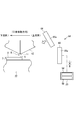
透過型のセンサ(透過型光電センサ)の構成について説明する。図6において、透過型のセンサ58は、光を発する発光素子60aを有する発光部60と、受光部62とを有する。受光部62は、発光素子60aが発光した光を受光する受光素子62aを有する。受光部62は、発光部60からの光を受光すると、受光信号を制御装置20へ出力する。発光部60からの光が遮断され、その光を受光部62が受光できないと、受光信号の出力が停止される。発光部60及び受光部62は、塗布器12と被塗布面8との間の隙間Kを挟んで、口金移動方向の上流側と下流側とに別れて設けられている。図6の構成では、上流側に受光部62が設けられ、下流側に発光部60が設けられている。
発光部60は、隙間Kであって少なくとも被塗布面8の近傍に向けて光を発し、受光部62はこの光を受光可能である。本開示では、発光部60は、隙間Kであって被塗布面8から塗布器12の先端面11までを含む領域に向けて光を発する。受光部62は、複数の受光素子62aを有している。受光部62において受光した範囲に応じて、受光信号(受光信号のレベル)が変化して出力される。つまり、受光部62の全体で光を受光した場合と、受光部62の一部で光を受光した場合とで、受光信号(受光信号のレベル)が異なる。
〔透過型のセンサ58を用いた場合の液付け完了検出の説明〕
前記構成を備える透過型のセンサ58を用いた液付け完了検出は、次のようにして行われる。塗布器12から塗布液Rが吐出されていない状態(図6参照)では、発光部60からの光を受光部62が検出する。塗布器12より隙間Kに対して塗布液Rが吐出され始めると、この塗布液Rによって隙間Kの一部が遮られる。隙間Kを通過する発光部60からの光が減少するが、液付け完了までの間、受光部62は一部の光を検出する。塗布液Rが吐出されていない状態と、吐出され始めた状態とで、受光信号に変化が生じるが、制御装置20の検出処理部54は、受光信号を取得している間、液付けがまだ完了していないと判定する。
前記構成を備える透過型のセンサ58を用いた液付け完了検出は、次のようにして行われる。塗布器12から塗布液Rが吐出されていない状態(図6参照)では、発光部60からの光を受光部62が検出する。塗布器12より隙間Kに対して塗布液Rが吐出され始めると、この塗布液Rによって隙間Kの一部が遮られる。隙間Kを通過する発光部60からの光が減少するが、液付け完了までの間、受光部62は一部の光を検出する。塗布液Rが吐出されていない状態と、吐出され始めた状態とで、受光信号に変化が生じるが、制御装置20の検出処理部54は、受光信号を取得している間、液付けがまだ完了していないと判定する。
図7に示すように、塗布器12から隙間Kに吐出された塗布液Rが被塗布面8に到達すると(つまり、液付けが完了すると)、その塗布液Rによって発光部60からの光が遮られ、受光部62は光を検出しない。すると、受光部62からは受光信号が出力されず、検出処理部54は、受光信号を取得しない。そこで、検出処理部54は、このタイミングで、液付けが完了したことを検出し、着液完了情報を生成する。以上のようにして、制御装置20により液付け完了の検出が行われる。生成された着液完了情報を、動作制御部56が取得する。すると、動作制御部56は、定量ポンプ42又はタンク36からの塗布液Rの供給を停止する。そして、動作制御部56は、塗布のための次の動作として、塗布器12内の塗布液Rを圧力調整器38によって所定圧力とする負圧状態にし、移動手段14によって被塗布面8に対して塗布器12の移動を開始させる。前記所定圧力は、圧力センサ30の計測値に基づいて設定される。
図6に示す形態では、検出装置として、透過型のセンサ58が用いられる。透過型のセンサ58は、隙間Kに向けられた受光部62を有すると共に、隙間Kを経て受光部62に向かう光を発する発光部60を有する。受光部62は、発光部60の光を受光すると受光信号を検出処理部54へ出力可能である。塗布器12から吐出された塗布液Rが被塗布面8に付着すると(図7参照)、この塗布液Rによって発光部60の光が遮断される。受光部62は、発光部60からの光が隙間Kにおいて遮断されると、受光信号が変化するように構成されている。なお、この変化には、受光信号が出力されていた状態から、出力されない状態に変化する場合も含まれる。つまり、発光部60からの光が隙間Kにおいて遮断されると、受光部62からの受光信号が途絶える。これにより、検出処理部54は、被塗布面8への液付けが完了したことの検出が可能となる。検出処理部54は、受光信号の変化に基づいて、隙間Kの塗布液Rが被塗布面8に付着したことを検出する。
受光部62は、前記説明した構成以外であってもよく、受光素子62aは一つであってもよい。この場合であっても、発光部60からの光が塗布液Rによって遮断されるまでは、受光部62はその光を受光できる。しかし、塗布液Rが被塗布面8に到達すると、その塗布液Rによって発光部60からの光が遮断され、受光部62は光を検出しない。すると、検出処理部54は、受光信号を取得しないタイミングで、液付けが完了したと検出することができる。
〔透過型のセンサ58を用いた場合の圧力の再設定処理の説明〕
透過型のセンサ58の構成は、前記のとおりである。受光部62は、発光部60の光を受光すると受光信号を検出処理部54へ出力可能である。受光部62は、発光部60の光が隙間Kの内の少なくとも塗布器12の先端面11側において遮断されると、受光信号が変化するように構成されている。
透過型のセンサ58の構成は、前記のとおりである。受光部62は、発光部60の光を受光すると受光信号を検出処理部54へ出力可能である。受光部62は、発光部60の光が隙間Kの内の少なくとも塗布器12の先端面11側において遮断されると、受光信号が変化するように構成されている。
透過型のセンサ58を用いた圧力の再設定処理は、次のようにして行われる。塗布器12から塗布液Rが吐出されていない状態(図6参照)では、発光部60からの光を受光部62が検出する。受光部62が光を検出すると、受光信号を制御装置20へ出力する。塗布器12より隙間Kに対して塗布液Rが吐出され始めると、この塗布液Rによって隙間Kの一部が遮られる。このため、隙間Kを通過する発光部60からの光が減少する。前記のとおり、受光部62からは、受光範囲に応じて受光信号が変化して出力される。そこで、検出処理部54は、受光信号の変化を判定する。検出処理部54は、受光信号が変化していると判定すると、塗布器12から塗布液Rの吐出が開始されたことを示す吐出開始情報を生成する。
動作制御部56は、吐出開始情報を取得する。すると、動作制御部56は、前記のように、受光信号が変化したと判定したタイミングでの塗布器12内の圧力(溜め部24の圧力)を、基準圧力として設定する。このために、圧力センサ30は、刻々と塗布器12内の圧力の計測を行う。この後、行われる塗布動作において、設定された前記基準圧力が基準とされる。このように基準圧力の設定(再設定)を行うことで、圧力センサ30による圧力計測の経時ばらつきを補正することができる。基準圧力の設定を行うことにより、塗布液Rが塗布器12から吐出される/吐出されないの境界(塗布器12内の圧力の境界)が設定される。このため、例えば、塗布器12の周囲の大気圧変化による塗布液Rの吐出量変化等を抑制することができる。
以上のように、塗布器12から塗布液Rの吐出が開始されると、この塗布液Rによって発光部60の光の遮断が開始され、受光部62からの受光信号が変化する。そこで、検出処理部54は、この受光信号の変化に基づいて、塗布器12から塗布液の吐出が開始されたことを検出し、吐出開始情報を生成することができる。そして、動作制御部56は、吐出開始情報が生成されると、受光信号の変化が生じたタイミング、つまり、塗布液の吐出が開始されたタイミングでの塗布器12内の圧力計測値(圧力センサ30による計測値)を、塗布動作のための基準圧力に設定(再設定)する。
以上の再設定の処理は、新たな基板7がステージ22に搬入され、その基板7に対する塗布動作を開始する前ごとに行われてもよいが、複数の塗布動作ごとに間欠的に行われてもよい。
〔検出装置の変形例(その2)〕
検出装置が、反射型のセンサである場合について説明する。反射型のセンサ(反射型光電センサ)の構成について説明する。図8において、反射型のセンサ64は、光を発する発光素子66aを有する発光部66と、受光部68とを有する。受光部68は、発光素子66aからの光の反射光を受光する受光素子68aを有する。発光部66からの光が対象物で反射し、この光(反射光)を受光部68が受光すると、受光部68は受光信号を制御装置20へ出力する。対象物が存在しておらず、発光部66からの光の反射が無い場合、受光部68は受光できず、受光信号が出力されない。
検出装置が、反射型のセンサである場合について説明する。反射型のセンサ(反射型光電センサ)の構成について説明する。図8において、反射型のセンサ64は、光を発する発光素子66aを有する発光部66と、受光部68とを有する。受光部68は、発光素子66aからの光の反射光を受光する受光素子68aを有する。発光部66からの光が対象物で反射し、この光(反射光)を受光部68が受光すると、受光部68は受光信号を制御装置20へ出力する。対象物が存在しておらず、発光部66からの光の反射が無い場合、受光部68は受光できず、受光信号が出力されない。
発光部66は、隙間Kに向かって光を発する。受光部68は、発光部66からの光であって、隙間Kに存在する塗布液R(図9参照)で反射した光を検出することができる。このために、発光部66及び受光部68は、隙間Kに向かって同じ側に設けられている。つまり、発光部66及び受光部68は、隙間Kを基準として、口金移動方向の上流側と下流側とのうちのいずれか一方側に設けられている。図8の形態では、口金移動方向の上流側に発光部66及び受光部68が設けられている。
発光部66は、少なくとも隙間Kであって被塗布面8の近傍に向けて光を発し、受光部68は、少なくとも隙間Kであって被塗布面8の近傍で反射した光を受光可能である。本開示では、隙間Kであって被塗布面8から塗布器12の先端面11までを含む領域に向けて光を発する。受光部68は、複数の受光素子68aを有していて、受光部68において受光した範囲に応じて、受光信号を出力する。つまり、受光部68の全体で光を受光した場合と、受光部68の一部で光を受光した場合とで、受光信号(受光信号のレベル)が異なる。
塗布器12から塗布液Rが吐出されていない状態(図8参照)では、隙間Kには塗布液Rが存在していないので、塗布液Rによる光の反射はゼロである。このため、受光部68から受光信号は出力されない。塗布器12から塗布液Rが吐出されると、隙間Kには塗布液Rが存在するので、塗布液Rによる光の反射が発生する。受光部68は、反射した光を検出することができる。受光部68は、受光信号を制御装置20へ出力し、制御装置20は、受光信号を取得する。
更に、塗布器12から吐出された塗布液Rが被塗布面8に到達すると(図9参照)、隙間Kには塗布液Rが存在するので、塗布液Rによる光の反射が発生する。受光部68は、反射した光を検出することができる。受光部68は、受光信号を制御装置20へ出力し、検出処理部54は、受光信号を取得する。ただし、塗布液Rが被塗布面8に到着する前後で、塗布液Rにおける反射面積が異なるため、受光信号(受光信号のレベル)が異なる。
〔反射型のセンサ64を用いた場合の液付け完了検出の説明〕
前記構成を備える反射型のセンサ64を用いた液付け完了検出は、次のようにして行われる。塗布器12から塗布液Rが吐出されていない状態(図8参照)では、発光部66からの光(反射光)を受光部68は検出できない。塗布器12より塗布液Rが吐出され始めると、受光部68は、塗布液Rからの反射光を検出する。受光部68が光を検出すると、受光信号が制御装置20へ出力される。塗布液Rの吐出が継続され、塗布液Rが被塗布面8に到達すると、この場合でも、受光部68は、塗布液Rからの反射光を検出し、受光信号を制御装置20へ出力する。
前記構成を備える反射型のセンサ64を用いた液付け完了検出は、次のようにして行われる。塗布器12から塗布液Rが吐出されていない状態(図8参照)では、発光部66からの光(反射光)を受光部68は検出できない。塗布器12より塗布液Rが吐出され始めると、受光部68は、塗布液Rからの反射光を検出する。受光部68が光を検出すると、受光信号が制御装置20へ出力される。塗布液Rの吐出が継続され、塗布液Rが被塗布面8に到達すると、この場合でも、受光部68は、塗布液Rからの反射光を検出し、受光信号を制御装置20へ出力する。
前記のとおり、受光部68は、受光した範囲に応じて、受光信号を変化させて出力する。そこで、受光信号を取得した検出処理部54は、受光信号(受光信号のレベル)と、予め設定されている閾値とを比較する。受光信号が前記閾値を超えていると、液付けが完了したことを検出し、着液完了情報が生成される。なお、前記閾値は、塗布液Rの液付けが完了する直前の状態で、受光部68が反射光を受光した場合に出力される受光信号のレベルである。検出処理部54は、受光信号が閾値を超えていると判定すると、そのタイミングで、液付けが完了したことを検出し、着液完了情報が生成され、出力される。以上のようにして、制御装置20により液付け完了の検出が行われる。生成された着液完了情報を、動作制御部56が取得する。すると、動作制御部56は、定量ポンプ42又はタンク36からの塗布液Rの供給を停止する。そして、動作制御部56は、塗布のための次の動作として、塗布器12内の塗布液Rを圧力調整器38によって所定圧力とする負圧状態にし、移動手段14によって被塗布面8に対して塗布器12の移動を開始させる。前記所定圧力は、圧力センサ30の計測値に基づいて設定される。
以上のように、図8に示す形態では、検出装置として、反射型のセンサ64が用いられる。反射型のセンサ64は、隙間Kに向けられた受光部62を有すると共に、隙間Kに向かって光を発する発光部66を有する。受光部68は、発光部66が発し隙間Kの塗布液Rで反射した光を受光すると受光信号を検出処理部54へ出力可能である。塗布器12から吐出された塗布液Rが被塗布面8に付着すると、この塗布液Rによって発光部66の光が反射され、受光部68はこの反射した光を受光し受光信号を検出処理部54へ出力することができる。そこで、検出処理部54は、受光信号に基づいて、隙間Kの塗布液Rが被塗布面8に付着したことを検出する。
〔反射型のセンサ64を用いた場合の圧力の再設定処理の説明〕
反射型のセンサ64の構成は、前記のとおりである。受光部62は、発光部60が発し隙間Kの塗布液Rで反射した光を受光すると受光信号を検出処理部54へ出力可能である。受光部62は、発光部60の光が隙間Kの内の少なくとも塗布器12の先端面11側において反射され、それを受光すると、受光信号が変化するように構成されている。
反射型のセンサ64の構成は、前記のとおりである。受光部62は、発光部60が発し隙間Kの塗布液Rで反射した光を受光すると受光信号を検出処理部54へ出力可能である。受光部62は、発光部60の光が隙間Kの内の少なくとも塗布器12の先端面11側において反射され、それを受光すると、受光信号が変化するように構成されている。
反射型のセンサ64を用いて行う圧力の再設定処理は、次のようにして行われる。塗布器12から塗布液Rが吐出されていない状態(図8参照)では、発光部66からの光(反射光)を受光部68が検出しない。塗布器12より塗布液Rが吐出され始めると、受光部68は、塗布液Rからの反射光を検出する。受光部68が光を検出すると、受光信号を制御装置20へ出力する。検出処理部54は、受光信号を取得すると、塗布器12から塗布液Rの吐出が開始されたと検出し、吐出開始情報を生成し、出力する。
このように、塗布器12から塗布液Rの吐出が開始されると、この塗布液Rによって発光部66の光が反射され、受光部68はこの反射した光を受光し受光信号を検出処理部54へ出力する。検出処理部54は、前記受光信号に基づいて、塗布器12から塗布液Rの吐出が開始されたことを検出し、吐出開始情報を生成することができる。そして、動作制御部56は、吐出開始情報が生成されると、受光信号を取得したタイミング、つまり、塗布液Rの吐出が開始されたタイミングでの塗布器12内の圧力計測値(圧力センサ30による計測値)を、塗布動作のための基準圧力に設定(再設定)する。
カメラ52又は透過型のセンサ58が検出装置として用いられる場合と同様、反射型のセンサ64を用いる場合においても、前記のように、基準圧力の設定が行われることで、塗布液Rが塗布器12から吐出される/吐出されないの境界(塗布器12内の圧力の境界)が設定される。この設定によって、圧力計測の経時ばらつきが補正されたり、大気圧変化による塗布液の吐出量変化等を抑制したりできる。
前記再設定の処理は、新たな基板7がステージ22に搬入され、その基板7に対する塗布動作を開始する前ごとに、行われてもよいが、複数の塗布動作ごとに間欠的に行われてもよい。
〔塗布装置10の異常の検出の説明〕
検出装置が、カメラ52であっても(図1)、透過型のセンサ58であっても(図6)、反射型のセンサ64であっても(図8)、前記液付け完了の検出では、塗布液Rが被塗布面8に到達した(着液した)タイミング(瞬間)を捉えることができる。また、前記圧力の再設定処理では、塗布器12から塗布液Rが吐出開始されたタイミング(瞬間)を捉えることができる。そこで、制御装置20の動作制御部56は、前記液付け動作の開始、つまり、定量ポンプ42の動作開始(又はタンク36からの塗布液Rの供給開始)から、前記タイミング(瞬間)までに要した時間をカウントする。
検出装置が、カメラ52であっても(図1)、透過型のセンサ58であっても(図6)、反射型のセンサ64であっても(図8)、前記液付け完了の検出では、塗布液Rが被塗布面8に到達した(着液した)タイミング(瞬間)を捉えることができる。また、前記圧力の再設定処理では、塗布器12から塗布液Rが吐出開始されたタイミング(瞬間)を捉えることができる。そこで、制御装置20の動作制御部56は、前記液付け動作の開始、つまり、定量ポンプ42の動作開始(又はタンク36からの塗布液Rの供給開始)から、前記タイミング(瞬間)までに要した時間をカウントする。
仮に塗布器12の溜め部24の塗布液Rにエアが混入している場合、溜め部24に塗布液Rが供給されても、エアの原因により(エア無しの場合と比較して)塗布器12からの塗布液Rの吐出開始又は液付け完了まで、多くの時間を要する。そこで、動作制御部56は、前記時間をカウントすると共に、そのカウント値と、予め設定されている閾値とを比較する。このカウント値は、隙間Kに塗布液Rが存在してない状態から、隙間Kに塗布液Rが存在している状態となるまでの、塗布装置10の動作に関する経過情報である。前記カウント値が前記閾値を越えている場合、異常が発生しているかもしれないことを示す異常情報、つまり、塗布器12内においてエアが混入しているかもしれないことを示す異常情報が、動作制御部56によって生成される。
異常情報が生成されると、動作制御部56は、塗布器12内のエアを外部へ排出するためのエアベントの動作を実行する。例えば、図示しないが、塗布器12の溜め部24と繋がるバルブを開いて、塗布液Rと共にエアを外部へ排出する。その後、動作制御部56によって塗布装置10は塗布動作に復帰する。
このように、動作制御部56は、隙間Kに塗布液Rが存在してない状態から、隙間Kに塗布液Rが存在している状態となるまでの、塗布装置10の動作に関する経過情報を取得する。そして、動作制御部56は、前記経過情報が示す値と閾値とを比較する。この比較に基づいて、塗布のための次の動作として、塗布動作前に確認すべきである塗布装置10の異常の検出を行う。このようにして、塗布装置10(塗布器12内のエアの混入)における異常が検出される。
前記経過情報としては、定量ポンプ42等の動作時間のカウント値以外であってもよく、塗布器12に供給された塗布液Rの流量であってもよく、定量ポンプ42の動作ストロークであってもよく、これらの内の少なくとも一つの情報であればよい。
〔本開示の塗布装置10について〕
以上のように、前記各形態の塗布装置10は、先端面11でスリット26が開口する塗布器12を備える。塗布器12と被塗布面8とが相対的に移動しながら、塗布器12の開口28から塗布液Rが吐出されることで、被塗布面8に塗布液Rが塗布される。塗布装置10は、カメラ52等により構成される検出装置と、検出処理部54と、動作制御部56とを備える。前記検出装置は、先端面11と被塗布面8との間の隙間Kに向けられた受光部を有する。検出処理部54は、前記検出装置からの検出信号に基づいて隙間Kの塗布液Rを検出する。動作制御部56は、検出処理部54の検出結果に基づいて塗布のための次の動作を実行する。
以上のように、前記各形態の塗布装置10は、先端面11でスリット26が開口する塗布器12を備える。塗布器12と被塗布面8とが相対的に移動しながら、塗布器12の開口28から塗布液Rが吐出されることで、被塗布面8に塗布液Rが塗布される。塗布装置10は、カメラ52等により構成される検出装置と、検出処理部54と、動作制御部56とを備える。前記検出装置は、先端面11と被塗布面8との間の隙間Kに向けられた受光部を有する。検出処理部54は、前記検出装置からの検出信号に基づいて隙間Kの塗布液Rを検出する。動作制御部56は、検出処理部54の検出結果に基づいて塗布のための次の動作を実行する。
この塗布装置10によって実行される塗布方法は、次のとおりである。すなわち、塗布器12と被塗布面8とが相対的に移動しながら、塗布器12の開口28から塗布液Rが吐出されることで、被塗布面8に塗布液を塗布する方法であって、塗布器12の先端面11と被塗布面8との間の隙間Kに検出装置の受光部が向けられていて、前記検出装置からの検出信号に基づいて隙間Kの塗布液Rを検出し、この検出の結果に基づいて、塗布のための次の動作を実行する。
前記塗布装置10及び塗布方法によれば、隙間Kに向けられた前記受光部により、塗布液Rの像又は影を捉えることで、隙間Kに塗布液Rが存在するか否かを検出することが可能となる。このため、塗布のための次の動作として、前記相対的な移動を開始させる塗布動作、この塗布動作のために塗布器12内の圧力を設定する圧力の再設定処理、及び、塗布品質に影響を与える可能性のある塗布装置10における異常を検出する動作等に、移行することができる。
〔その他〕
隙間Kにおける塗布液Rの検出をより確実とするために、検出装置がカメラ52である場合も、光源(発光部)が設けられるのが好ましい。
隙間Kにおける塗布液Rの検出をより確実とするために、検出装置がカメラ52である場合も、光源(発光部)が設けられるのが好ましい。
前記各形態のようにカメラ52等の検出装置が用いられる塗布装置10は、キャピラリ塗布以外に、他の塗布方法にも適用可能である。他の塗布方法としては、例えば、定量ポンプ等で塗布液を塗布器に供給することによって、塗布液を強制的に塗布器から吐出させて行う塗布方法であってもよい。
基板7が円形である場合について説明したが、矩形であってもよい。
今回開示した実施形態は全ての点で例示であって制限的なものではない。本発明の権利範囲は、上述の実施形態に限定されるものではなく、特許請求の範囲の範囲に記載された構成と均等の範囲内での全ての変更が含まれる。
8:被塗布面 9:着液部 10:塗布装置
11:先端面 12:塗布器 26:スリット
28:開口 52:カメラ(検出装置) 53:撮像素子(受光部)
54:検出処理部 56:動作制御部 58:透過型のセンサ(検出装置)
60:発光部 62:受光部 64:反射型のセンサ(検出装置)
66:発光部 68:受光部 K:隙間
R:塗布液
11:先端面 12:塗布器 26:スリット
28:開口 52:カメラ(検出装置) 53:撮像素子(受光部)
54:検出処理部 56:動作制御部 58:透過型のセンサ(検出装置)
60:発光部 62:受光部 64:反射型のセンサ(検出装置)
66:発光部 68:受光部 K:隙間
R:塗布液
Claims (10)
- 先端面でスリットが開口する塗布器を備え、当該塗布器と被塗布面とが相対的に移動しながら前記塗布器の開口から塗布液が吐出されることで当該被塗布面に塗布液を塗布する装置であって、
前記先端面と前記被塗布面との間の隙間に向けられた受光部を有する検出装置と、
前記検出装置からの検出信号に基づいて前記隙間の塗布液を検出する検出処理部と、
前記検出処理部の検出結果に基づいて塗布のための次の動作を実行する動作制御部と、
を備える、塗布装置。 - 前記検出装置は、前記受光部として撮像素子を有するカメラであり、
前記検出処理部は、前記カメラの撮影画像を画像処理し、前記隙間における塗布液の像の占める割合と塗布液以外の像の占める割合との内の少なくとも一方の割合に基づいて、
前記隙間の塗布液が前記被塗布面に付着したことを検出する、請求項1に記載の塗布装置。 - 前記検出装置は、前記隙間を経て前記受光部に向かう光を発する発光部を更に有していて、
前記受光部は、前記発光部の光を受光すると受光信号を前記検出処理部へ出力可能であって、当該光が前記隙間において遮断されると当該受光信号が変化する構成であり、
前記検出処理部は、前記受光信号の変化に基づいて、前記隙間の塗布液が前記被塗布面に付着したことを検出する、請求項1に記載の塗布装置。 - 前記検出装置は、前記隙間に向かって光を発する発光部を更に有していて、
前記受光部は、前記発光部が発し前記隙間の塗布液で反射した光を受光すると受光信号を前記検出処理部へ出力可能であり、
前記検出処理部は、前記受光信号に基づいて、前記隙間の塗布液が前記被塗布面に付着したことを検出する、請求項1に記載の塗布装置。 - 前記検出装置は、前記受光部として撮像素子を有するカメラであり、
前記検出処理部は、前記カメラの撮影画像を画像処理し、前記隙間における塗布液の像の占める割合と塗布液以外の像の占める割合との内の少なくとも一方の割合に基づいて、
前記塗布器から塗布液の吐出が開始されたことを検出し、
塗布液の吐出開始が検出されると、前記動作制御部は、塗布液の吐出が開始されたタイミングでの前記塗布器内の圧力計測値を、塗布動作のための基準圧力に設定する、請求項1~4のいずれか一項に記載の塗布装置。 - 前記検出装置は、前記隙間を経て前記受光部に向かう光を発する発光部を更に有していて、
前記受光部は、前記発光部の光を受光すると受光信号を前記検出処理部へ出力可能であって、当該光が前記隙間の内の少なくとも前記塗布器の前記先端面側において遮断されると当該受光信号が変化する構成であり、
前記検出処理部は、前記受光信号の変化に基づいて、前記塗布器から塗布液の吐出が開始されたことを検出し、
塗布液の吐出開始が検出されると、前記動作制御部は、塗布液の吐出が開始されたタイミングでの前記塗布器内の圧力計測値を、塗布動作のための基準圧力に設定する、請求項1~4のいずれか一項に記載の塗布装置。 - 前記検出装置は、前記隙間に向かって光を発する発光部を更に有していて、
前記受光部は、前記発光部が発し前記隙間の塗布液で反射した光を受光すると受光信号を前記検出処理部へ出力可能であり、
前記検出処理部は、前記受光信号に基づいて、前記塗布器から塗布液の吐出が開始されたことを検出し、
塗布液の吐出開始が検出されると、前記動作制御部は、塗布液の吐出が開始されたタイミングでの前記塗布器内の圧力計測値を、塗布動作のための基準圧力に設定する、請求項1~4のいずれか一項に記載の塗布装置。 - 前記動作制御部は、前記隙間に塗布液が存在してない状態から、当該隙間に塗布液が存在している状態となるまでの、当該塗布装置の動作に関する経過情報を取得し、
前記動作制御部は、当該経過情報が示す値と閾値とを比較することで、前記次の動作として、当該塗布装置における異常を検出する、請求項1~7のいずれか一項に記載の塗布装置。 - 前記検出装置は、前記受光部として撮像素子を有するカメラであり、
前記カメラの撮像対象は、前記被塗布面の内の塗布液の着液部と、前記塗布器の前記先端面の内の前記着液部に対向する対向位置との間の隙間を含む範囲であり、
前記検出処理部は、前記カメラの撮影画像を画像処理し、
前記隙間の塗布液を検出するために前記検出処理部が画像処理に用いる処理対象は、前記撮像画像の内の一部であって、前記隙間における、前記着液部の少なくとも一部と、前記対向位置の少なくとも一部との間の領域である、請求項1~8のいずれか一項に記載の塗布装置。 - 先端面でスリットが開口する塗布器と、被塗布面と、が相対的に移動しながら当該塗布器の開口から塗布液が吐出されることで当該被塗布面に塗布液を塗布する方法であって、
前記先端面と前記被塗布面との間の隙間に検出装置の受光部が向けられていて、
前記検出装置の検出信号に基づいて前記隙間の塗布液を検出し、
当該検出の結果に基づいて、塗布のための次の動作を実行する、塗布方法。
Priority Applications (1)
| Application Number | Priority Date | Filing Date | Title |
|---|---|---|---|
| PCT/JP2020/011811 WO2021186583A1 (ja) | 2020-03-17 | 2020-03-17 | 塗布装置及び塗布方法 |
Applications Claiming Priority (1)
| Application Number | Priority Date | Filing Date | Title |
|---|---|---|---|
| PCT/JP2020/011811 WO2021186583A1 (ja) | 2020-03-17 | 2020-03-17 | 塗布装置及び塗布方法 |
Publications (1)
| Publication Number | Publication Date |
|---|---|
| WO2021186583A1 true WO2021186583A1 (ja) | 2021-09-23 |
Family
ID=77771927
Family Applications (1)
| Application Number | Title | Priority Date | Filing Date |
|---|---|---|---|
| PCT/JP2020/011811 Ceased WO2021186583A1 (ja) | 2020-03-17 | 2020-03-17 | 塗布装置及び塗布方法 |
Country Status (1)
| Country | Link |
|---|---|
| WO (1) | WO2021186583A1 (ja) |
Citations (10)
| Publication number | Priority date | Publication date | Assignee | Title |
|---|---|---|---|---|
| JP2003117466A (ja) * | 2001-10-16 | 2003-04-22 | Toray Ind Inc | 塗布方法および装置 |
| JP2003247949A (ja) * | 2002-02-25 | 2003-09-05 | Toppan Printing Co Ltd | スリットダイコートの検査装置および検査方法 |
| JP2005114499A (ja) * | 2003-10-07 | 2005-04-28 | Toppan Printing Co Ltd | ダイコートビードの検査装置及びその検査方法 |
| JP2006075698A (ja) * | 2004-09-08 | 2006-03-23 | Fuji Photo Film Co Ltd | 光学機能フィルムの製造方法、光学機能フィルム、偏光板用保護フィルム及び偏光板、画像表示装置 |
| JP2007301440A (ja) * | 2006-05-09 | 2007-11-22 | Toray Ind Inc | 熱可塑性樹脂シートの製造方法および熱可塑性樹脂シート |
| WO2010106979A1 (ja) * | 2009-03-19 | 2010-09-23 | タツモ株式会社 | 基板用塗布装置 |
| JP2012181036A (ja) * | 2011-02-28 | 2012-09-20 | Toray Eng Co Ltd | 塗布装置および塗布方法 |
| JP2014079669A (ja) * | 2012-10-15 | 2014-05-08 | Toyota Motor Corp | 塗工装置および塗工方法 |
| JP2015181977A (ja) * | 2014-03-20 | 2015-10-22 | 東レ株式会社 | 間隙維持方法、間隙維持装置及び塗布装置 |
| JP2016030253A (ja) * | 2014-07-30 | 2016-03-07 | 株式会社ヒラノテクシード | 塗工装置 |
-
2020
- 2020-03-17 WO PCT/JP2020/011811 patent/WO2021186583A1/ja not_active Ceased
Patent Citations (10)
| Publication number | Priority date | Publication date | Assignee | Title |
|---|---|---|---|---|
| JP2003117466A (ja) * | 2001-10-16 | 2003-04-22 | Toray Ind Inc | 塗布方法および装置 |
| JP2003247949A (ja) * | 2002-02-25 | 2003-09-05 | Toppan Printing Co Ltd | スリットダイコートの検査装置および検査方法 |
| JP2005114499A (ja) * | 2003-10-07 | 2005-04-28 | Toppan Printing Co Ltd | ダイコートビードの検査装置及びその検査方法 |
| JP2006075698A (ja) * | 2004-09-08 | 2006-03-23 | Fuji Photo Film Co Ltd | 光学機能フィルムの製造方法、光学機能フィルム、偏光板用保護フィルム及び偏光板、画像表示装置 |
| JP2007301440A (ja) * | 2006-05-09 | 2007-11-22 | Toray Ind Inc | 熱可塑性樹脂シートの製造方法および熱可塑性樹脂シート |
| WO2010106979A1 (ja) * | 2009-03-19 | 2010-09-23 | タツモ株式会社 | 基板用塗布装置 |
| JP2012181036A (ja) * | 2011-02-28 | 2012-09-20 | Toray Eng Co Ltd | 塗布装置および塗布方法 |
| JP2014079669A (ja) * | 2012-10-15 | 2014-05-08 | Toyota Motor Corp | 塗工装置および塗工方法 |
| JP2015181977A (ja) * | 2014-03-20 | 2015-10-22 | 東レ株式会社 | 間隙維持方法、間隙維持装置及び塗布装置 |
| JP2016030253A (ja) * | 2014-07-30 | 2016-03-07 | 株式会社ヒラノテクシード | 塗工装置 |
Similar Documents
| Publication | Publication Date | Title |
|---|---|---|
| JP2020116519A (ja) | 塗布装置及び塗布方法 | |
| US8136477B2 (en) | Apparatus for and method of dispensing chemical solution in spin-coating equipment | |
| CN102270560B (zh) | 液处理装置 | |
| US20240272554A1 (en) | Method of detecting liquid in liquid processing apparatus | |
| US20160217997A1 (en) | Substrate processing device, recordng medium, and control method | |
| EP1614000A2 (en) | Optical arrangement of autofocus elements for use with immersion lithography | |
| US11378388B2 (en) | Substrate inspection method, substrate inspection apparatus and recording medium | |
| CN114377891B (zh) | 喷嘴的位置调整方法和液处理装置 | |
| KR20190029439A (ko) | 기판 처리 장치, 기판 처리 방법 및 컴퓨터 기억 매체 | |
| US10529604B2 (en) | Substrate position adjustment method, storage medium and substrate treatment system | |
| US7197176B2 (en) | Mark position detecting apparatus and mark position detecting method | |
| WO2021186583A1 (ja) | 塗布装置及び塗布方法 | |
| US7316515B2 (en) | Liquid processing apparatus processing a substrate surface with a processing liquid, liquid processing method, and liquid condition detection apparatus detecting fluctuation of the processing liquid | |
| US8094289B2 (en) | Scanning exposure apparatus and device manufacturing method | |
| WO2010055551A1 (ja) | 処理液吐出検査方法、処理液吐出検査装置及びコンピュータ読取可能な記録媒体 | |
| TWI765173B (zh) | 檢查裝置及檢查方法 | |
| US9594314B2 (en) | Exposure apparatus, alignment method, and device manufacturing method | |
| TWI712775B (zh) | 半導體製程及半導體設備 | |
| CN109016864A (zh) | 一种精准定位静电打印系统和方法 | |
| CN102033071A (zh) | 涂镀状态检测方法 | |
| US20230314960A1 (en) | Peripheral edge processing apparatus, peripheral edge processing method, and computer-readable recording medium | |
| US20260107732A1 (en) | Substrate processing method and substrate processing apparatus | |
| CN110568733B (zh) | 半导体工艺及半导体设备 | |
| TWI904690B (zh) | 基板邊緣檢測方法 | |
| TW200419311A (en) | Developer and developer nozzle |
Legal Events
| Date | Code | Title | Description |
|---|---|---|---|
| 121 | Ep: the epo has been informed by wipo that ep was designated in this application |
Ref document number: 20925014 Country of ref document: EP Kind code of ref document: A1 |
|
| NENP | Non-entry into the national phase |
Ref country code: DE |
|
| NENP | Non-entry into the national phase |
Ref country code: JP |
|
| 122 | Ep: pct application non-entry in european phase |
Ref document number: 20925014 Country of ref document: EP Kind code of ref document: A1 |