WO2021184786A1 - 一种布置在燃机出口烟道内部的尿素直喷热解脱硝装置 - Google Patents
一种布置在燃机出口烟道内部的尿素直喷热解脱硝装置 Download PDFInfo
- Publication number
- WO2021184786A1 WO2021184786A1 PCT/CN2020/128466 CN2020128466W WO2021184786A1 WO 2021184786 A1 WO2021184786 A1 WO 2021184786A1 CN 2020128466 W CN2020128466 W CN 2020128466W WO 2021184786 A1 WO2021184786 A1 WO 2021184786A1
- Authority
- WO
- WIPO (PCT)
- Prior art keywords
- urea
- gas turbine
- direct injection
- outlet flue
- injection pyrolysis
- Prior art date
- Legal status (The legal status is an assumption and is not a legal conclusion. Google has not performed a legal analysis and makes no representation as to the accuracy of the status listed.)
- Ceased
Links
Images


Classifications
-
- B—PERFORMING OPERATIONS; TRANSPORTING
- B01—PHYSICAL OR CHEMICAL PROCESSES OR APPARATUS IN GENERAL
- B01D—SEPARATION
- B01D53/00—Separation of gases or vapours; Recovering vapours of volatile solvents from gases; Chemical or biological purification of waste gases, e.g. engine exhaust gases, smoke, fumes, flue gases, aerosols
- B01D53/34—Chemical or biological purification of waste gases
- B01D53/92—Chemical or biological purification of waste gases of engine exhaust gases
- B01D53/94—Chemical or biological purification of waste gases of engine exhaust gases by catalytic processes
- B01D53/9404—Removing only nitrogen compounds
- B01D53/9409—Nitrogen oxides
- B01D53/9431—Processes characterised by a specific device
-
- B—PERFORMING OPERATIONS; TRANSPORTING
- B01—PHYSICAL OR CHEMICAL PROCESSES OR APPARATUS IN GENERAL
- B01D—SEPARATION
- B01D53/00—Separation of gases or vapours; Recovering vapours of volatile solvents from gases; Chemical or biological purification of waste gases, e.g. engine exhaust gases, smoke, fumes, flue gases, aerosols
- B01D53/34—Chemical or biological purification of waste gases
- B01D53/92—Chemical or biological purification of waste gases of engine exhaust gases
- B01D53/94—Chemical or biological purification of waste gases of engine exhaust gases by catalytic processes
- B01D53/9495—Controlling the catalytic process
-
- B—PERFORMING OPERATIONS; TRANSPORTING
- B01—PHYSICAL OR CHEMICAL PROCESSES OR APPARATUS IN GENERAL
- B01D—SEPARATION
- B01D2251/00—Reactants
- B01D2251/20—Reductants
- B01D2251/206—Ammonium compounds
- B01D2251/2062—Ammonia
Definitions
- the invention belongs to the technical field of SCR denitrification, and relates to a urea direct injection pyrolysis denitrification device arranged inside a flue of a gas turbine outlet.
- the reducing agent for SCR denitration reaction can choose liquid ammonia, ammonia water and urea.
- Liquid ammonia evaporation technology is mature and reliable, and investment and operating costs are also low.
- liquid ammonia is a major source of danger and restricts the application of liquid ammonia technology.
- ammonia water generally chooses 20% by mass ammonia water, which has high transportation costs and the source of ammonia water is not extensive, which limits the application of ammonia production technology to a certain extent. Therefore, the production of ammonia from urea has received more and more attention in the SCR denitration technology.
- urea ammonia production technology includes urea pyrolysis and urea hydrolysis ammonia production technology.
- the traditional urea pyrolysis ammonia production technology can lead the high-temperature flue gas from the outlet flue of the gas turbine with a high-temperature dilution fan and send it to the urea pyrolysis furnace, and spray atomization in the urea pyrolysis furnace
- the latter urea solution uses the heat of the high-temperature flue gas to pyrolyze the urea solution to generate the reducing agent required for the denitration reaction, and then is sent to the ammonia injection grid arranged in the waste heat boiler, and the ammonia injection grid is sprayed and mixed with the flue gas Then the denitration reaction takes place on the surface of the catalyst.
- Urea hydrolysis technology uses steam at a certain temperature and pressure (0.4 ⁇ 0.6MPa, 140 ⁇ 160°C) to hydrolyze the urea solution in a hydrolysis reactor, and then high temperature flue gas is drawn out through a high temperature dilution fan in the waste heat boiler. After being mixed with the hydrolysis reaction product gas in the mixer, it enters the ammonia injection grid arranged in the waste heat boiler, and the ammonia injection grid is sprayed and mixed with the flue gas to cause denitration reaction on the surface of the catalyst.
- These two kinds of urea ammonia technologies require more equipment, complex systems, heavy operation and maintenance workloads, and both have a certain amount of energy consumption. At the same time, the initial investment required to achieve zone adjustment is relatively high.
- the purpose of the present invention is to overcome the above shortcomings of the prior art and provide a urea direct injection pyrolysis denitrification device arranged inside the gas turbine outlet flue, which can realize automatic zone adjustment and has low energy consumption.
- the urea direct injection thermal denitrification device arranged inside the gas turbine outlet flue of the present invention includes the gas turbine outlet flue, a urea solution input pipeline, a desalinated water input pipeline, a waste heat boiler, a chimney, and several urine Plain direct injection pyrolysis spray gun and several metering modules;
- the outlet flue of the gas turbine is connected to the inlet of the chimney via a waste heat boiler.
- the waste heat boiler is provided with a catalyst module, and each urea direct injection pyrolysis spray gun is located in the outlet flue of the gas turbine, and each urea direct injection pyrolysis spray gun is along the combustion path.
- the outlet flue of the machine is evenly distributed on the same cross section, and one metering module corresponds to a urea direct injection pyrolysis spray gun.
- the metering module includes a mixer, a first manual valve, a second manual valve, an automatic regulating valve and a self-operated decompression
- the urea solution input pipeline is connected to the inlet of the mixer through the first manual valve and automatic regulating valve
- the demineralized water input pipeline is connected to the inlet of the mixer through the second manual valve and self-operated pressure reducing valve.
- the outlet is connected with the inlet of the urea direct injection pyrolysis spray gun.
- the spray direction of the urea direct injection pyrolysis spray gun is the same as the direction of flue gas flow.
- the mixed solution sprayed by each urea direct-injection pyrolysis spray gun covers the entire cross-section of the flue at the outlet of the gas turbine.
- the flow rate of the solution entering each urea direct injection pyrolysis spray gun is automatically adjusted to make the NH 3 /NOx molar ratio on the inlet cross section of the catalyst module uniform.
- each urea direct injection pyrolysis spray gun is located in the gas turbine outlet flue, and the desalinated water output from the desalinated water input pipeline is sequentially
- the pressure is regulated by the second manual valve and the self-operated pressure reducing valve and enters the mixer.
- the urea solution output from the urea solution input pipeline is automatically adjusted by the first manual valve and the automatic regulating valve and then enters the mixer.
- the mixer outputs The mixed solution of urea is injected into the flue duct of the gas turbine by direct injection pyrolysis spray gun for heating and pyrolysis.
- the present invention does not require a urea pyrolysis furnace or a hydrolysis reactor or a high-temperature dilution fan .
- the ammonia injection grille and the valve group before the ammonia injection grille have simple systems and low energy consumption.
- the mixed solution output by each urea direct injection pyrolysis spray gun is individually controlled to achieve automatic zone adjustment, which can be used in different working conditions.
- a good distribution uniformity of the NH 3 /NOx molar ratio at the entrance section of the catalyst is obtained under the following conditions, and the denitrification device starts and responds quickly to variable conditions.
- Figure 1 is a schematic diagram of the structure of the present invention
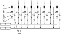
- Figure 2 is a schematic diagram of the structure of the metering module 1 in the present invention.
- Fig. 3 is a distribution diagram of each urea direct injection pyrolysis spray gun 2 in the present invention.
- 1 is the metering module
- 2 is the urea direct injection pyrolysis spray gun
- 3 is the gas turbine outlet flue
- 4 is the catalyst module
- 51 is the first manual valve
- 52 is the second manual valve
- 6 is the automatic regulating valve
- 7 is a mixer
- 8 is a self-operated pressure reducing valve
- 9 is a waste heat boiler
- 10 is a chimney
- 11 is a urea solution input pipeline
- 12 is a desalinated water input pipeline.
- the urea direct injection pyrolysis denitrification device arranged inside the gas turbine outlet flue of the present invention includes the gas turbine outlet flue 3, the urea solution input pipe 11, and the desalinated water input pipe 12 , Waste heat boiler 9, chimney 10, several urea direct injection pyrolysis spray guns 2 and several metering modules 1; the gas turbine outlet flue 3 is connected to the inlet of the chimney 10 through the waste heat boiler 9, wherein the waste heat boiler 9 is provided with a catalyst module 4.
- Each urea direct injection pyrolysis spray gun 2 is located in the gas turbine outlet flue 3, and each urea direct injection pyrolysis spray gun 2 is evenly distributed along the same cross section of the gas turbine outlet flue 3.
- One metering module 1 corresponds to one urine Direct injection pyrolysis spray gun 2.
- the metering module 1 includes a mixer 7, a first manual valve 51, a second manual valve 52, an automatic regulating valve 6 and a self-operated pressure reducing valve 8.
- the urea solution input pipeline 11 passes through the first
- the manual valve 51 and the automatic regulating valve 6 are connected to the inlet of the mixer 7, and the desalinated water input pipeline 12 is connected to the inlet of the mixer 7 through the second manual valve 52 and the self-operated pressure reducing valve 8, and the outlet of the mixer 7 It is connected with the inlet of the urea direct injection pyrolysis spray gun 2.
- the spray direction of the urea direct injection pyrolysis spray gun 2 is the same as the flue gas flow direction.
- the mixed solution sprayed by each urea direct injection pyrolysis spray gun 2 covers the entire cross section of the gas turbine outlet flue 3.
- the distribution of NOx concentration on the cross section adjusts the flow rate of the solution entering each urea direct injection pyrolysis spray gun 2 to make the NH 3 /NOx molar ratio on the inlet section of the catalyst module 4 uniform.
- the demineralized water output from the demineralized water input pipeline 12 is sequentially regulated by the second manual valve 52 and the self-operated pressure reducing valve 8 and enters the mixer 7, and the urea solution input pipe 11 outputs urea with a mass concentration of 30%-50%.
- the solution is automatically adjusted by the first manual valve 51 and the automatic control valve 6 and then enters the mixer 7.
- the mixed solution output by the mixer 7 is injected into the gas turbine outlet flue 3 through the urea direct injection pyrolysis spray gun 2 for heating. Then, the flue gas enters the waste heat boiler 9 and the SCR denitration reaction occurs under the catalysis of the catalyst module 4 to generate harmless N 2 and H 2 O, which are discharged into the atmosphere through the chimney 10.
Landscapes
- Chemical & Material Sciences (AREA)
- Engineering & Computer Science (AREA)
- Combustion & Propulsion (AREA)
- Health & Medical Sciences (AREA)
- Biomedical Technology (AREA)
- Environmental & Geological Engineering (AREA)
- Analytical Chemistry (AREA)
- General Chemical & Material Sciences (AREA)
- Oil, Petroleum & Natural Gas (AREA)
- Chemical Kinetics & Catalysis (AREA)
- Treating Waste Gases (AREA)
- Exhaust Gas Treatment By Means Of Catalyst (AREA)
Abstract
提供一种布置在燃机出口烟道内部的尿素直喷热解脱硝装置。其中,燃机出口烟道经余热锅炉与烟囱的入口相连通,余热锅炉中设置有催化剂模块,各尿素直喷热解喷枪均位于燃机出口烟道内,且各尿素直喷热解喷枪沿燃机出口烟道同一横截面上均匀分布,一个计量模块对应一个尿素直喷热解喷枪,所述计量模块包括混合器、第一手动阀门、第二手动阀门、自动调节阀及自力式减压阀,尿素溶液输入管道经第一手动阀门及自动调节阀与混合器的入口相连通,除盐水输入管道经第二手动阀门及自力式减压阀与混合器的入口相连通,混合器的出口与尿素直喷热解喷枪的入口相连通。该装置能够实现自动分区调节,且能耗较低。
Description
本发明属于SCR脱硝技术领域,涉及一种布置在燃机出口烟道内部的尿素直喷热解脱硝装置。
燃气蒸汽联合循环发电技术以其清洁高效的特点在我国得到了广泛的应用。近年,随着国家环保标准的提高,很多地区对于燃机的NOx排放提出了更加严格的要求,例如深圳市人民政府印发的深府[2017]1号文件“深圳市大气环境质量提升计划(2017-2020年)”要求新建燃气发电机组NOx排放浓度控制在15mg/m
3以下,2020年前E级燃气发电机组NOx排放浓度控制在25mg/m
3以下,F级燃气发电机组NOx排放浓度控制在15mg/m
3以下。在这种情况下,仅依靠燃气轮机的低氮燃烧技术是很难达到NOx排放要求的。采用SCR脱硝技术成为一种可行的方案。
通常SCR脱硝反应还原剂可选择液氨、氨水和尿素。液氨蒸发制氨技术成熟可靠,投资和运行成本也较低,但液氨是重大危险源,限制液氨制氨技术的应用。而氨水一般选择20%质量浓度的氨水,其运输成本高,且氨水的来源也并不广泛,在一定程度上也限制了氨水制氨技术的应用。因此尿素制氨在SCR脱硝技术中得到了越来越多的关注。目前尿素制氨技术有尿素热解和尿素水解制氨技术。对于燃气蒸汽联合循环机组来说,传统的尿素热解制氨技术可以从燃机出口烟道将高温烟气用高 温稀释风机引出送入尿素热解炉,在尿素热解炉中喷入雾化后的尿素溶液,利用高温烟气的热量使尿素溶液热解生成脱硝反应所需要的还原剂,然后再送入布置在余热锅炉中的喷氨格栅,由喷氨格栅喷出与烟气混合后在催化剂表面发生脱硝反应。尿素水解制氨技术是使用一定温度和压力(0.4~0.6MPa、140~160℃)的蒸汽在水解反应器内使尿素溶液发生水解反应,然后在余热锅炉内通过高温稀释风机引出高温烟气,与水解反应产品气在混合器中混合后进入布置在余热锅炉中的喷氨格栅,由喷氨格栅喷出与烟气混合后在催化剂表面发生脱硝反应。这两种尿素制氨技术所需要的设备较多,系统复杂,运行维护工作量大,且都有一定的能耗,同时实现分区调节所需要的初投资较高。
发明内容
本发明的目的在于克服上述现有技术的缺点,提供了一种布置在燃机出口烟道内部的尿素直喷热解脱硝装置,该装置能够实现自动分区调节,且能耗较低。
为达到上述目的,本发明所述的布置在燃机出口烟道内部的尿素直喷热解脱硝装置包括燃机出口烟道、尿素溶液输入管道、除盐水输入管道、余热锅炉、烟囱、若干尿素直喷热解喷枪及若干计量模块;
燃机出口烟道经余热锅炉与烟囱的入口相连通,其中,余热锅炉中设置有催化剂模块,各尿素直喷热解喷枪均位于燃机出口烟道内,且各尿素直喷热解喷枪沿燃机出口烟道同一横截面上均匀分布,一个计量模块对应一个尿素直喷热解喷枪,所述计量模块包括混合器、第一手动阀门、第二手动阀门、自动调节阀及自力式减压阀,尿素溶液输入管道经 第一手动阀门及自动调节阀与混合器的入口相连通,除盐水输入管道经第二手动阀门及自力式减压阀与混合器的入口相连通,混合器的出口与尿素直喷热解喷枪的入口相连通。
尿素直喷热解喷枪的喷射方向与烟气流动的方向相同。
各尿素直喷热解喷枪喷射的混合溶液覆盖燃机出口烟道的整个横截面。
在工作时,根据余热锅炉出口横截面上NOx浓度的分布情况自动调节进入到各尿素直喷热解喷枪中溶液的流量,使催化剂模块入口截面上NH
3/NOx摩尔比均匀。
本发明具有以下有益效果:
本发明所述的布置在燃机出口烟道内部的尿素直喷热解脱硝装置在具体操作时,各尿素直喷热解喷枪均位于燃机出口烟道内,除盐水输入管道输出的除盐水依次经第二手动阀门及自力式减压阀调压进入到混合器中,尿素溶液输入管道输出的尿素溶液依次经第一手动阀门及自动调节阀自动调节后进入到混合器中,混合器输出的混合溶液经尿素直喷热解喷枪喷射到燃机出口烟道中进行加热热解,与传统尿素热解或尿素水解技术相比,本发明不需要尿素热解炉或水解反应器、高温稀释风机、喷氨格栅及喷氨格栅前阀组等设备,系统简单,能耗较低,通过各尿素直喷热解喷枪输出的混合溶液单独控制,以实现自动分区调节,能够在不同工况下获得良好的催化剂入口截面NH
3/NOx摩尔比分布均匀性,且脱硝装置的启动和变工况响应速度快。
图1为本发明的结构示意图;
图2为本发明中计量模块1的结构示意图;
图3为本发明中各尿素直喷热解喷枪2的分布图。
其中,1为计量模块、2为尿素直喷热解喷枪、3为燃机出口烟道、4为催化剂模块、51为第一手动阀门、52为第二手动阀门、6为自动调节阀、7为混合器、8为自力式减压阀、9为余热锅炉、10为烟囱、11为尿素溶液输入管道、12为除盐水输入管道。
下面结合附图对本发明做进一步详细描述:
参考图1、图2及图3,本发明所述的布置在燃机出口烟道内部的尿素直喷热解脱硝装置包括燃机出口烟道3、尿素溶液输入管道11、除盐水输入管道12、余热锅炉9、烟囱10、若干尿素直喷热解喷枪2及若干计量模块1;燃机出口烟道3经余热锅炉9与烟囱10的入口相连通,其中,余热锅炉9中设置有催化剂模块4,各尿素直喷热解喷枪2均位于燃机出口烟道3内,且各尿素直喷热解喷枪2沿燃机出口烟道3同一横截面上均匀分布,一个计量模块1对应一个尿素直喷热解喷枪2,所述计量模块1包括混合器7、第一手动阀门51、第二手动阀门52、自动调节阀6及自力式减压阀8,尿素溶液输入管道11经第一手动阀门51及自动调节阀6与混合器7的入口相连通,除盐水输入管道12经第二手动阀门52及自力式减压阀8与混合器7的入口相连通,混合器7的出口与尿素直喷热解喷枪2的入口相连通。
尿素直喷热解喷枪2的喷射方向与烟气流动的方向相同,各尿素直 喷热解喷枪2喷射的混合溶液覆盖燃机出口烟道3的整个横截面,在工作时,根据余热锅炉3横截面上NOx浓度的分布情况调节进入到各尿素直喷热解喷枪2中溶液的流量,使催化剂模块4入口截面上NH
3/NOx摩尔比均匀。
除盐水输入管道12输出的除盐水依次经第二手动阀门52及自力式减压阀8调压进入到混合器7中,尿素溶液输入管道11输出的质量浓度为30%-50%的尿素溶液依次经第一手动阀门51及自动调节阀6自动调节后进入到混合器7中,混合器7输出的混合溶液经尿素直喷热解喷枪2喷射到燃机出口烟道3中进行加热热解,再跟随烟气进入到余热锅炉9中,然后在催化剂模块4的催化作用下发生SCR脱硝反应,生成无害的N
2和H
2O,经过烟囱10排入大气。
显然,上述实施例仅仅是为清楚地说明所作的举例,而并非对实施方式的限定。对于所述领域的普通技术人员来说,在上述说明的基础上还可以做出其它不同形式的变化或变动。这里无需也无法对所有的实施方式予以穷举。而由此所引申出的显而易见的变化或变动仍处于本发明创造的保护范围之中。
Claims (4)
- 一种布置在燃机出口烟道内部的尿素直喷热解脱硝装置,其特征在于,包括燃机出口烟道(3)、尿素溶液输入管道(11)、除盐水输入管道(12)、余热锅炉(9)、烟囱(10)、若干尿素直喷热解喷枪(2)及若干计量模块(1);燃机出口烟道(3)经余热锅炉(9)与烟囱(10)的入口相连通,其中,余热锅炉(9)中设置有催化剂模块(4),各尿素直喷热解喷枪(2)均位于燃机出口烟道(3)内,且各尿素直喷热解喷枪(2)沿燃机出口烟道(3)同一横截面上均匀分布,一个计量模块(1)对应一个尿素直喷热解喷枪(2),所述计量模块(1)包括混合器(7)、第一手动阀门(51)、第二手动阀门(52)、自动调节阀(6)及自力式减压阀(8),尿素溶液输入管道(11)经第一手动阀门(51)及自动调节阀(6)与混合器(7)的入口相连通,除盐水输入管道(12)经第二手动阀门(52)及自力式减压阀(8)与混合器(7)的入口相连通,混合器(7)的出口与尿素直喷热解喷枪(2)的入口相连通。
- 根据权利要求1所述的布置在燃机出口烟道内部的尿素直喷热解脱硝装置,其特征在于,尿素直喷热解喷枪(2)的喷射方向与烟气流动的方向相同。
- 根据权利要求1所述的布置在燃机出口烟道内部的尿素直喷热解脱硝装置,其特征在于,各尿素直喷热解喷枪(2)喷射的混合溶液覆盖燃机出口烟道(3)的整个横截面。
- 根据权利要求1所述的布置在燃机出口烟道内部的尿素直喷热解脱硝装置,其特征在于,在工作时,根据余热锅炉(9)出口横截面上NOx浓度的分布情况自动调节进入到各尿素直喷热解喷枪(2)中溶液的流量, 使催化剂模块(4)入口截面上NH 3/NOx摩尔比均匀。
Applications Claiming Priority (2)
| Application Number | Priority Date | Filing Date | Title |
|---|---|---|---|
| CN202010183637.4A CN111229039A (zh) | 2020-03-16 | 2020-03-16 | 一种布置在燃机出口烟道内部的尿素直喷热解脱硝装置 |
| CN202010183637.4 | 2020-03-16 |
Publications (1)
| Publication Number | Publication Date |
|---|---|
| WO2021184786A1 true WO2021184786A1 (zh) | 2021-09-23 |
Family
ID=70862261
Family Applications (1)
| Application Number | Title | Priority Date | Filing Date |
|---|---|---|---|
| PCT/CN2020/128466 Ceased WO2021184786A1 (zh) | 2020-03-16 | 2020-11-12 | 一种布置在燃机出口烟道内部的尿素直喷热解脱硝装置 |
Country Status (2)
| Country | Link |
|---|---|
| CN (1) | CN111229039A (zh) |
| WO (1) | WO2021184786A1 (zh) |
Cited By (12)
| Publication number | Priority date | Publication date | Assignee | Title |
|---|---|---|---|---|
| CN113908689A (zh) * | 2021-10-27 | 2022-01-11 | 杭州锅炉集团股份有限公司 | 一种布置在余热锅炉入口烟道的大管束结构的喷氨格栅 |
| CN113926385A (zh) * | 2021-10-25 | 2022-01-14 | 上海洁昊环保股份有限公司 | 一种尿素催化热解制氨的设备及方法 |
| CN114294631A (zh) * | 2022-01-05 | 2022-04-08 | 湖北聚之德生态环境工程技术有限公司 | 一种空气源热能回收与循环使用方法 |
| CN114870627A (zh) * | 2022-05-30 | 2022-08-09 | 西安热工研究院有限公司 | 一种燃煤电厂scr脱硝分区精准喷氨控制方法及系统 |
| CN115072739A (zh) * | 2022-06-15 | 2022-09-20 | 大唐环境产业集团股份有限公司 | 一种直流耦合式尿素热解装置 |
| CN115608150A (zh) * | 2022-10-27 | 2023-01-17 | 北京龙源惟德能源科技有限公司 | 一种节能型脱硝尿素水解制氨系统 |
| CN115715928A (zh) * | 2022-11-18 | 2023-02-28 | 江苏华南新能源科技有限公司 | 燃机余热锅炉脱硝设备 |
| CN116492843A (zh) * | 2023-05-25 | 2023-07-28 | 北京市中环博业环境工程技术有限公司 | 一种脱硝方法 |
| CN116835610A (zh) * | 2023-05-25 | 2023-10-03 | 苏州西热节能环保技术有限公司 | 一种快速清堵尿素制氨系统及其控制方法 |
| CN116850762A (zh) * | 2023-09-04 | 2023-10-10 | 济南作为科技有限公司 | 脱硝喷氨控制系统及方法 |
| CN118993213A (zh) * | 2024-10-17 | 2024-11-22 | 浙江浙能嘉华发电有限公司 | 一种尿素水解制氨工艺废液资源化利用工艺 |
| CN119425371A (zh) * | 2024-09-24 | 2025-02-14 | 西安热工研究院有限公司 | 一种新型管道伴热方式的尿素直喷热解系统 |
Families Citing this family (6)
| Publication number | Priority date | Publication date | Assignee | Title |
|---|---|---|---|---|
| CN111229039A (zh) * | 2020-03-16 | 2020-06-05 | 西安西热锅炉环保工程有限公司 | 一种布置在燃机出口烟道内部的尿素直喷热解脱硝装置 |
| CN112169593A (zh) * | 2020-11-10 | 2021-01-05 | 西安热工研究院有限公司 | 一种适用于燃机scr脱硝的精准直喷热解装置 |
| CN112387115A (zh) * | 2020-11-21 | 2021-02-23 | 西安热工研究院有限公司 | 一种高温高尘烟气尿素溶液多点等量分配喷射装置及方法 |
| CN114288851A (zh) * | 2022-02-16 | 2022-04-08 | 西安西热锅炉环保工程有限公司 | 一种宽负荷燃机余热锅炉脱硝系统 |
| CN115144231B (zh) * | 2022-06-21 | 2023-04-07 | 浙江兴核智拓科技有限公司 | 一种适用于燃机余热锅炉脱硝装置的尿素直喷分区测控系统 |
| CN116617853A (zh) * | 2023-05-24 | 2023-08-22 | 北京华能长江环保科技研究院有限公司 | 脱硝制氨装置 |
Citations (8)
| Publication number | Priority date | Publication date | Assignee | Title |
|---|---|---|---|---|
| JPH08103634A (ja) * | 1994-10-04 | 1996-04-23 | Hitachi Zosen Corp | 尿素を用いる脱硝装置 |
| CN205659558U (zh) * | 2016-04-15 | 2016-10-26 | 中国大唐集团科学技术研究院有限公司西北分公司 | 一种尿素热解脱硝计量分配系统 |
| CN207237684U (zh) * | 2017-09-11 | 2018-04-17 | 西安热工研究院有限公司 | 燃煤电站锅炉烟气水分回收及细颗粒物脱除的系统 |
| CN109173723A (zh) * | 2018-10-30 | 2019-01-11 | 中国海洋石油集团有限公司 | 用于燃气轮机和余热锅炉发电机组的简化scr脱硝系统 |
| CN209476010U (zh) * | 2018-11-26 | 2019-10-11 | 华能北京热电有限责任公司 | 一种基于燃气蒸汽联合循环机组的尿素脱硝系统 |
| CN111229039A (zh) * | 2020-03-16 | 2020-06-05 | 西安西热锅炉环保工程有限公司 | 一种布置在燃机出口烟道内部的尿素直喷热解脱硝装置 |
| CN211837273U (zh) * | 2020-03-16 | 2020-11-03 | 西安西热锅炉环保工程有限公司 | 一种布置在燃机出口烟道内部的尿素直喷热解脱硝装置 |
| CN112169593A (zh) * | 2020-11-10 | 2021-01-05 | 西安热工研究院有限公司 | 一种适用于燃机scr脱硝的精准直喷热解装置 |
Family Cites Families (1)
| Publication number | Priority date | Publication date | Assignee | Title |
|---|---|---|---|---|
| JP4381881B2 (ja) * | 2004-05-13 | 2009-12-09 | バブコック日立株式会社 | 排煙脱硝装置とその起動方法 |
-
2020
- 2020-03-16 CN CN202010183637.4A patent/CN111229039A/zh active Pending
- 2020-11-12 WO PCT/CN2020/128466 patent/WO2021184786A1/zh not_active Ceased
Patent Citations (8)
| Publication number | Priority date | Publication date | Assignee | Title |
|---|---|---|---|---|
| JPH08103634A (ja) * | 1994-10-04 | 1996-04-23 | Hitachi Zosen Corp | 尿素を用いる脱硝装置 |
| CN205659558U (zh) * | 2016-04-15 | 2016-10-26 | 中国大唐集团科学技术研究院有限公司西北分公司 | 一种尿素热解脱硝计量分配系统 |
| CN207237684U (zh) * | 2017-09-11 | 2018-04-17 | 西安热工研究院有限公司 | 燃煤电站锅炉烟气水分回收及细颗粒物脱除的系统 |
| CN109173723A (zh) * | 2018-10-30 | 2019-01-11 | 中国海洋石油集团有限公司 | 用于燃气轮机和余热锅炉发电机组的简化scr脱硝系统 |
| CN209476010U (zh) * | 2018-11-26 | 2019-10-11 | 华能北京热电有限责任公司 | 一种基于燃气蒸汽联合循环机组的尿素脱硝系统 |
| CN111229039A (zh) * | 2020-03-16 | 2020-06-05 | 西安西热锅炉环保工程有限公司 | 一种布置在燃机出口烟道内部的尿素直喷热解脱硝装置 |
| CN211837273U (zh) * | 2020-03-16 | 2020-11-03 | 西安西热锅炉环保工程有限公司 | 一种布置在燃机出口烟道内部的尿素直喷热解脱硝装置 |
| CN112169593A (zh) * | 2020-11-10 | 2021-01-05 | 西安热工研究院有限公司 | 一种适用于燃机scr脱硝的精准直喷热解装置 |
Non-Patent Citations (1)
| Title |
|---|
| DONG CHEN, ZHAO SHUCHUN, XU HONGJIE, WANG XIAOBING, CHANG LEI, NIU GUOPING: "Key points of SNCR denitrification technology for coal fired boilers", THERMAL POWER GENERATION, vol. 45, no. 12, 31 December 2016 (2016-12-31), XP055851391, DOI: 10.3969/j.issn.1002-3364.2016.12.073 * |
Cited By (15)
| Publication number | Priority date | Publication date | Assignee | Title |
|---|---|---|---|---|
| CN113926385A (zh) * | 2021-10-25 | 2022-01-14 | 上海洁昊环保股份有限公司 | 一种尿素催化热解制氨的设备及方法 |
| CN113908689A (zh) * | 2021-10-27 | 2022-01-11 | 杭州锅炉集团股份有限公司 | 一种布置在余热锅炉入口烟道的大管束结构的喷氨格栅 |
| CN114294631A (zh) * | 2022-01-05 | 2022-04-08 | 湖北聚之德生态环境工程技术有限公司 | 一种空气源热能回收与循环使用方法 |
| CN114870627A (zh) * | 2022-05-30 | 2022-08-09 | 西安热工研究院有限公司 | 一种燃煤电厂scr脱硝分区精准喷氨控制方法及系统 |
| CN115072739B (zh) * | 2022-06-15 | 2024-01-19 | 大唐环境产业集团股份有限公司 | 一种直流耦合式尿素热解装置 |
| CN115072739A (zh) * | 2022-06-15 | 2022-09-20 | 大唐环境产业集团股份有限公司 | 一种直流耦合式尿素热解装置 |
| CN115608150A (zh) * | 2022-10-27 | 2023-01-17 | 北京龙源惟德能源科技有限公司 | 一种节能型脱硝尿素水解制氨系统 |
| CN115715928A (zh) * | 2022-11-18 | 2023-02-28 | 江苏华南新能源科技有限公司 | 燃机余热锅炉脱硝设备 |
| CN116835610A (zh) * | 2023-05-25 | 2023-10-03 | 苏州西热节能环保技术有限公司 | 一种快速清堵尿素制氨系统及其控制方法 |
| CN116492843A (zh) * | 2023-05-25 | 2023-07-28 | 北京市中环博业环境工程技术有限公司 | 一种脱硝方法 |
| CN116492843B (zh) * | 2023-05-25 | 2024-03-12 | 北京市中环博业环境工程技术有限公司 | 一种脱硝方法 |
| CN116850762A (zh) * | 2023-09-04 | 2023-10-10 | 济南作为科技有限公司 | 脱硝喷氨控制系统及方法 |
| CN119425371A (zh) * | 2024-09-24 | 2025-02-14 | 西安热工研究院有限公司 | 一种新型管道伴热方式的尿素直喷热解系统 |
| CN119425371B (zh) * | 2024-09-24 | 2026-01-23 | 西安热工研究院有限公司 | 一种管道伴热方式的尿素直喷热解系统 |
| CN118993213A (zh) * | 2024-10-17 | 2024-11-22 | 浙江浙能嘉华发电有限公司 | 一种尿素水解制氨工艺废液资源化利用工艺 |
Also Published As
| Publication number | Publication date |
|---|---|
| CN111229039A (zh) | 2020-06-05 |
Similar Documents
| Publication | Publication Date | Title |
|---|---|---|
| WO2021184786A1 (zh) | 一种布置在燃机出口烟道内部的尿素直喷热解脱硝装置 | |
| CN205216566U (zh) | 一种sncr脱硝装置 | |
| CN113426296A (zh) | 一种基于燃机scr脱硝的节能型尿素水解制氨脱硝装置 | |
| CN112169593A (zh) | 一种适用于燃机scr脱硝的精准直喷热解装置 | |
| CN104548931A (zh) | 一种采用高温烟气作为热源的尿素热解制氨气装置 | |
| CN202527072U (zh) | 基于尿素溶液或氨水的scr烟气脱硝装置 | |
| CN209476010U (zh) | 一种基于燃气蒸汽联合循环机组的尿素脱硝系统 | |
| CN215170388U (zh) | 一种基于主燃区喷氨脱硝的燃气轮机系统 | |
| CN202527063U (zh) | 基于尿素溶液或氨水的组合式烟气脱硝装置 | |
| CN211837273U (zh) | 一种布置在燃机出口烟道内部的尿素直喷热解脱硝装置 | |
| CN104329946B (zh) | 一种焦炉烟道废气脱硝及余热回收的一体化系统 | |
| CN207025089U (zh) | 一种直接利用锅炉高温烟气实现尿素热解的制氨系统 | |
| CN111229037A (zh) | 氨水作为还原剂的燃气蒸汽联合循环机组脱硝装置及方法 | |
| CN111214954A (zh) | 一种基于燃气蒸汽联合循环机组的尿素脱硝系统及方法 | |
| CN211988034U (zh) | 氨水作为还原剂的燃气蒸汽联合循环机组脱硝装置 | |
| CN113357006B (zh) | 一种基于主燃区喷氨脱硝的燃气轮机系统及其脱硝方法 | |
| CN211098339U (zh) | 一种用于燃煤锅炉的烟气深度脱硝装置 | |
| CN115144231B (zh) | 一种适用于燃机余热锅炉脱硝装置的尿素直喷分区测控系统 | |
| CN210057905U (zh) | 一种燃气轮机余热锅炉脱硝系统 | |
| CN113797747B (zh) | 一种尿素热解制氨系统及其使用方法 | |
| CN214681049U (zh) | 一种布置在燃机出口圆形烟道的高效氨水直喷喷氨系统 | |
| CN214552503U (zh) | 一种适用于燃机scr脱硝的精准直喷热解装置 | |
| CN204429102U (zh) | 一种利用scr系统的尿素溶液烟道内直喷热解装置 | |
| CN109999661A (zh) | 一种燃气轮机余热锅炉脱硝系统及其工作过程 | |
| CN222218612U (zh) | 一种结构简单又节能的氨水蒸发装置 |
Legal Events
| Date | Code | Title | Description |
|---|---|---|---|
| 121 | Ep: the epo has been informed by wipo that ep was designated in this application |
Ref document number: 20925362 Country of ref document: EP Kind code of ref document: A1 |
|
| NENP | Non-entry into the national phase |
Ref country code: DE |
|
| 122 | Ep: pct application non-entry in european phase |
Ref document number: 20925362 Country of ref document: EP Kind code of ref document: A1 |