WO2021182356A1 - ロボットの制御装置、ロボットシステム、ロボット制御方法 - Google Patents
ロボットの制御装置、ロボットシステム、ロボット制御方法 Download PDFInfo
- Publication number
- WO2021182356A1 WO2021182356A1 PCT/JP2021/008814 JP2021008814W WO2021182356A1 WO 2021182356 A1 WO2021182356 A1 WO 2021182356A1 JP 2021008814 W JP2021008814 W JP 2021008814W WO 2021182356 A1 WO2021182356 A1 WO 2021182356A1
- Authority
- WO
- WIPO (PCT)
- Prior art keywords
- robot
- condition
- external force
- processor
- satisfied
- Prior art date
- Legal status (The legal status is an assumption and is not a legal conclusion. Google has not performed a legal analysis and makes no representation as to the accuracy of the status listed.)
- Ceased
Links
Images





Classifications
-
- B—PERFORMING OPERATIONS; TRANSPORTING
- B25—HAND TOOLS; PORTABLE POWER-DRIVEN TOOLS; MANIPULATORS
- B25J—MANIPULATORS; CHAMBERS PROVIDED WITH MANIPULATION DEVICES
- B25J19/00—Accessories fitted to manipulators, e.g. for monitoring, for viewing; Safety devices combined with or specially adapted for use in connection with manipulators
- B25J19/06—Safety devices
-
- B—PERFORMING OPERATIONS; TRANSPORTING
- B25—HAND TOOLS; PORTABLE POWER-DRIVEN TOOLS; MANIPULATORS
- B25J—MANIPULATORS; CHAMBERS PROVIDED WITH MANIPULATION DEVICES
- B25J9/00—Program-controlled manipulators
- B25J9/16—Program controls
- B25J9/1674—Program controls characterised by safety, monitoring, diagnostic
-
- B—PERFORMING OPERATIONS; TRANSPORTING
- B25—HAND TOOLS; PORTABLE POWER-DRIVEN TOOLS; MANIPULATORS
- B25J—MANIPULATORS; CHAMBERS PROVIDED WITH MANIPULATION DEVICES
- B25J13/00—Controls for manipulators
- B25J13/08—Controls for manipulators by means of sensing devices, e.g. viewing or touching devices
- B25J13/085—Force or torque sensors
-
- B—PERFORMING OPERATIONS; TRANSPORTING
- B25—HAND TOOLS; PORTABLE POWER-DRIVEN TOOLS; MANIPULATORS
- B25J—MANIPULATORS; CHAMBERS PROVIDED WITH MANIPULATION DEVICES
- B25J9/00—Program-controlled manipulators
- B25J9/16—Program controls
- B25J9/1674—Program controls characterised by safety, monitoring, diagnostic
- B25J9/1676—Avoiding collision or forbidden zones
-
- G—PHYSICS
- G05—CONTROLLING; REGULATING
- G05B—CONTROL OR REGULATING SYSTEMS IN GENERAL; FUNCTIONAL ELEMENTS OF SUCH SYSTEMS; MONITORING OR TESTING ARRANGEMENTS FOR SUCH SYSTEMS OR ELEMENTS
- G05B2219/00—Program-control systems
- G05B2219/30—Nc systems
- G05B2219/39—Robotics, robotics to robotics hand
- G05B2219/39091—Avoid collision with moving obstacles
-
- G—PHYSICS
- G05—CONTROLLING; REGULATING
- G05B—CONTROL OR REGULATING SYSTEMS IN GENERAL; FUNCTIONAL ELEMENTS OF SUCH SYSTEMS; MONITORING OR TESTING ARRANGEMENTS FOR SUCH SYSTEMS OR ELEMENTS
- G05B2219/00—Program-control systems
- G05B2219/30—Nc systems
- G05B2219/40—Robotics, robotics mapping to robotics vision
- G05B2219/40201—Detect contact, collision with human
-
- G—PHYSICS
- G05—CONTROLLING; REGULATING
- G05B—CONTROL OR REGULATING SYSTEMS IN GENERAL; FUNCTIONAL ELEMENTS OF SUCH SYSTEMS; MONITORING OR TESTING ARRANGEMENTS FOR SUCH SYSTEMS OR ELEMENTS
- G05B2219/00—Program-control systems
- G05B2219/30—Nc systems
- G05B2219/40—Robotics, robotics mapping to robotics vision
- G05B2219/40599—Force, torque sensor integrated in joint
Definitions
- the present invention relates to a robot control device, a robot system, and a robot control method.
- Patent Document 1 A control device that controls a robot to stop its operation when it comes into contact with a surrounding object is known (for example, Patent Document 1).
- the control device of the robot having the movable element exceeds the external force acquisition unit that acquires the external force applied to the movable element when the robot is operating and the first threshold value set in advance.
- a first condition determination unit that determines whether or not the first condition that an external force is applied to the movable element is satisfied, and a second condition determination that determines whether or not the second condition that the movable element is moving is satisfied.
- the operation of the robot is stopped when both the first condition and the second condition are satisfied, and the operation of the robot is continued when at least one of the first condition and the second condition is not satisfied. It is equipped with a control unit.
- the control method of a robot having a movable element acquires an external force applied to the movable element while the robot is operating, and the external force exceeding a predetermined first threshold value is movable. It is determined whether or not the first condition that the movable element has been added is satisfied, and whether or not the second condition that the movable element is moving is satisfied, and both the first condition and the second condition are satisfied. When the robot operation is stopped, the robot operation is continued when at least one of the first condition and the second condition is not satisfied.
- the operation of the robot is stopped to ensure the safety of the work, while at least one of the first condition and the second condition is satisfied. If it is not satisfied, it is possible to prevent the work efficiency from being lowered by continuing the operation of the robot.
- the robot system 10 includes a robot 12 and a control device 50 that controls the robot 12.
- the robot 12 is a vertical articulated robot, and has a robot base 14, a swivel body 16, a lower arm portion 18, an upper arm portion 20, a wrist portion 22, and an end effector 24.
- the robot base 14 is fixed to the floor A of the work cell.
- the swivel body 16 is provided on the robot base 14 so as to be able to swivel around a vertical axis.
- the lower arm portion 18 is provided on the swivel body 16 so as to be rotatable around a horizontal axis.
- the upper arm portion 20 is rotatably provided at the tip end portion of the lower arm portion 18.
- the wrist portion 22 is rotatably provided at the tip portion of the upper arm portion 20, and the end effector 24 is detachably attached to the tip portion of the wrist portion 22.
- the wrist portion 22 may be configured to rotate the end effector 24 around a plurality of axes orthogonal to each other.
- the end effector 24 is, for example, a robot hand, a welding torch, a cutting tool, a laser processing head, a paint coating device, or the like, and is a predetermined operation (work handling, welding, cutting process, etc.) for a work (not shown). Laser processing, coating, etc.).
- the robot 12 includes a first servomotor 26, a first joint shaft 28, a second servomotor 30, a second joint shaft 32, a third servomotor 34, a third joint shaft 36, and a fourth servo. It further has a motor 38 and a fourth joint shaft 40.
- the first servomotor 26 is built in the robot base 14 and rotates the first joint shaft 28 around a vertical shaft.
- the first joint shaft 28 is connected to the swivel cylinder 16 and transmits the rotational force of the first servomotor 26 to the swivel cylinder 16.
- the second servomotor 30 is provided on the swivel body 16 and rotates the second joint shaft 32 around the horizontal shaft.
- the second joint shaft 32 is connected to the lower arm portion 18 and transmits the rotational force of the second servomotor 30 to the lower arm portion 18.
- the third servomotor 34 is provided on the lower arm portion 18 and rotates the third joint shaft 36.
- the third joint shaft 36 is connected to the upper arm portion 20 and transmits the rotational force of the third servomotor 34 to the upper arm portion 20.
- the fourth servomotor 38 is provided on the upper arm portion 20 and rotates the fourth joint shaft 40.
- the fourth joint shaft 40 is connected to the wrist portion 22 and transmits the rotational force of the fourth servomotor 38 to the wrist portion 22.
- These plurality of servomotors 26, 30, 34, and 38 rotate the joint shafts 28, 32, 36, and 40, respectively, under the command from the control device 50, whereby the swivel body 16, the lower arm portion 18, and the lower arm portion 18.
- the upper arm portion 20, the wrist portion 22, and the end effector 24 are rotated, respectively. Therefore, the joint shafts 28, 32, 36 and 40, the swivel body 16, the lower arm 18, the upper arm 20, the wrist 22, and the end effector 24 constitute the movable elements of the robot 12.
- the joint shafts 28, 32, 36 and 40 are provided with a plurality of force sensors 42, 44, 46 and 48, respectively.
- Each of the force sensors 42, 44, 46 and 48 is a torque sensor.
- the first force sensor 42 detects the force (specifically, torque) applied to the first joint shaft 28, and the second force sensor 44 applies to the second joint shaft 32. Detects force (specifically, torque).
- the third force sensor 46 detects the force (specifically, torque) applied to the third joint shaft 36
- the fourth force sensor 48 detects the force (specifically) applied to the fourth joint shaft 40. The torque) is detected.
- the first force sensor 42, the second force sensor 44, the third force sensor 46, and the fourth force sensor 48 transmit the detected force (torque) detection data to the control device 50, respectively.
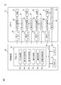
- the control device 50 is a computer having a processor 52, a memory 54, and an I / O interface 56.
- the processor 52 has a CPU, a GPU, or the like, and is communicably connected to the memory 54 and the I / O interface 56 via the bus 58.
- the processor 52 performs calculations for realizing various functions of the control device 50, which will be described later, while communicating with the memory 54 and the I / O interface 56.
- the memory 54 has a RAM, a ROM, or the like, and temporarily or permanently stores various data.
- the memory 54 stores in advance a work program WP for causing the robot 12 to execute a predetermined work.
- the work program WP includes position data of a teaching point at which the end effector 24 should be positioned for work, a command statement for positioning the end effector 24 at the teaching point, and a movement locus and a movement speed between the two teaching points. It is a computer program that contains the information of.
- This work program WP can be constructed, for example, by teaching the robot 12 an operation of sequentially positioning the end effector 24 at the teaching point.
- the I / O interface 56 has, for example, an Ethernet (registered trademark) port, a USB port, an optical fiber connector, an HDMI (registered trademark) terminal, or the like, and wirelessly or wired data with an external device under the command of the processor 52. Communicate with.
- the servomotors 26, 30, 34 and 38 and the force sensors 42, 44, 46 and 48 are communicably connected to the I / O interface 56.
- the processor 52 transmits commands to the servomotors 26, 30, 34, and 38 via the I / O interface 56 according to the work program WP stored in the memory 54, and causes the robot 12 to perform a predetermined work.
- the robot 12 (specifically, a movable element) is operated. Further, the processor 52 acquires the detection data detected by the force sensors 42, 44, 46 and 48 while the robot 12 is operating via the I / O interface 56, and stores the detection data in the memory 54.
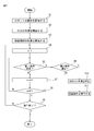
- the flow shown in FIG. 3 is started when the processor 52 receives an automatic work start command from an operator, a host controller, or a computer program (for example, the above-mentioned work program WP).
- step S1 the processor 52 starts the operation of the robot 12. Specifically, the processor 52 transmits commands to the servomotors 26, 30, 34, and 38 according to the work program WP, and moves the end effector 24 to each teaching point by the movable element of the robot 12, and the end effector. A series of operations for performing work on the work is started by 24.
- step S2 the processor 52 starts acquiring the external force applied to the movable element of the robot 12. Specifically, the processor 52 continuously (for example, periodically) detects data from the first force sensor 42, the second force sensor 44, the third force sensor 46, and the fourth force sensor 48. get.
- the processor 52 acquires the detection data
- the first force sensor 42 and the second force sensor 44 due to the mass of the robot 12 and the inertial force generated by the operation of the robot 12.
- the forces acting on the third force sensor 46 and the fourth force sensor 48 are calculated respectively. These internal forces can be calculated by substituting the mass of each movable element of the robot 12, the posture of the robot 12, and the moving speed of each movable element of the robot 12 into a known kinematic equation.
- the processor 52 subtracts the component of the internal force acting on the first force sensor 42 from the detection data of the first force sensor 42 (that is, the torque applied to the first joint shaft 28).
- the external force torque ET 1 applied to the joint shaft 28 of 1 is calculated.
- the processor 52 uses the detection data of the second force sensor 44, the third force sensor 46, and the fourth force sensor 48 (that is, the second joint axis 32, the third joint axis 36, and the third joint axis 36).
- External force torque applied to the second joint shaft 32, the third joint shaft 36, and the fourth joint shaft 40 by subtracting the corresponding internal force components from the torque applied to the joint shaft 40 of 4. Calculate ET 2 , ET 3 , and ET 4 , respectively.
- step S3 the processor 52 starts acquiring the movement information of the movable element of the robot 12. Specifically, the processor 52 uses the first joint shaft 28 in the moving direction MD 1 and the moving speed MV 1 , the second joint shaft 32 in the moving direction MD 2 and the moving speed MV 2 , and the third joint shaft 28 as movement information. The moving direction MD 3 and the moving speed MV 3 of the joint shaft 36, and the moving direction MD 4 and the moving speed MV 4 of the fourth joint shaft 40 are acquired.
- the servomotors 26, 30, 34 and 38 are provided with rotation detectors (encoders, Hall elements, etc.), respectively. These rotation detectors detect the rotation position (or rotation angle) of the servomotors 26, 30, 34 and 38 (or the joint shafts 28, 32, 36 and 40), respectively, and use the position feedback FB as a position feedback FB to the control device 50. Send.
- the processor 52 may acquire the moving direction MD n and the moving speed MV n from the commands (position command, speed command, etc.) transmitted to the servomotors 26, 30, 34, and 38.
- the processor 52 analyzes the work program WP, and from the information such as the position data of the teaching point, the instruction statement, the movement locus, or the movement speed included in the work program WP, the movement direction MD n and the movement speed MV n may be acquired.
- the processor 52 is the moving direction acquisition unit 62 (FIG. 2) for acquiring the moving direction MD n of the movable elements (joint axes 28, 32, 36, 40), and the movable element. It functions as a speed acquisition unit 64 that acquires the movement speed MV n.
- the movement direction MD n indicates the rotation direction of the nth joint axes 28, 32, 36, 40
- the movement speed MV n is the nth joint axes 28, 32, 36, 40.
- step S4 the processor 52 sets the number "n” that identifies the nth joint axes 28, 32, 36, 40 to "1".
- step S5 the processor 52 satisfies the first condition that the external force torque ET n exceeding the predetermined threshold value ⁇ n (first threshold value) is applied to the nth joint shaft 28, 32, 36 or 40. Judge whether or not.
- the processor 52 uses the processor 52 when the external force torque ET n in the direction opposite to the moving direction MD n of the nth joint axes 28, 32, 36 or 40 exceeds the threshold value ⁇ n. It is determined that the first condition is satisfied.
- processor 52 most recently acquired, the movement of the third direction of the external force torque ET 3 applied to the joint shaft 36, a third joint axis 36 obtained in synchronism with the external force torque ET 3 It is determined whether or not the magnitude of the external force torque ET 3 exceeds the threshold value ⁇ 3 in the opposite direction to the direction MD 3.
- the processor 52 satisfies the first condition for the third joint axis 36 (that is, when the direction of the external force torque ET 3 is opposite to the moving direction MD 3 and its magnitude exceeds the threshold value ⁇ 3). YES) is determined, and the process proceeds to step S6.
- processor 52 uses the first joint axis 36 for the third joint axis 36. It is determined that the condition is not satisfied (that is, NO), and the process proceeds to step S7.
- processor 52 first the condition that the external force ET n exceeding the threshold value alpha n is applied to the movable element (joint axis 28, 32, 36 or 40 of the n) It functions as a first condition determination unit 66 (FIG. 2) for determining whether or not.
- step S6 the processor 52 determines whether or not the second condition that the nth joint axis 28, 32, 36 or 40 is moving is satisfied. Specifically, the processor 52 moves the moving speed MV of the nth joint shaft 28, 32, 36 or 40 acquired in synchronization with the external force torque ET n when the first condition is determined in the latest step S5. When n exceeds a predetermined threshold value ⁇ n (second threshold value), it is determined that the second condition is satisfied.
- ⁇ n second threshold value
- step S6 the processor 52 is acquired in synchronization with the external force torque ET 3 when the first condition is determined in the latest step S5.
- the processor 52 determines that the second condition is satisfied (that is, YES) for the third joint axis 36. If the processor 52 determines YES, the processor 52 proceeds to step S10.
- the processor 52 determines that the second condition is not satisfied (that is, NO) for the third joint axis 36, and proceeds to step S7. As described above, in the present embodiment, the processor 52 determines whether or not the second condition that the movable element (nth joint axis 28, 32, 36 or 40) is moving is satisfied. It functions as a determination unit 68 (FIG. 2).
- the processor 52 at step S6, the acceleration a n of the joint axes 28, 32, 36 or 40 of the n-th, when the threshold is exceeded gamma n a predetermined, it is determined that the second condition is satisfied May be good.
- the acceleration a n for example, by differentiating the moving speed MV n acquired in synchronization with an external force torque ET n when it is determined the first condition in the most recent step S5 time, can be obtained.
- step S8 the processor 52 determines whether or not the number “n” that identifies the nth joint axes 28, 32, 36, and 40 is “5” or more. This number "5" is the total number of the joint axes 28, 32, 36, 40 of the robot 12 + 1.
- step S9 the processor 52 determines whether or not a series of operations of the robot 12 has been completed. For example, the processor 52 can determine whether or not the operation of the robot 12 is completed based on the information of the work program WP and the position feedback FB.
- the processor 52 determines that the operation of the robot 12 is completed (that is, YES)
- the processor 52 stops the robot 12 and ends the flow shown in FIG.
- the processor 52 determines that the operation of the robot 12 has not been completed (that is, NO)
- the processor 52 returns to step S4. Then, the processor 52 loops steps S4 to S9 until it determines YES in step S6 or S9.
- step S6 the processor 52 stops the operation of the robot 12 in step S10.
- the processor 52 sends a stop command to all the servomotors 26, 30, 34 and 38 to stop the operations of these servomotors 26, 30, 34 and 38 at the same time, thereby causing the robot 12 to operate. Stop it.
- each servomotor 26, 30, 34 and 38 has a braking mechanism for braking the output shafts (or joint shafts 28, 32, 36 and 40) of the servomotors 26, 30, 34 and 38. Is provided. Then, by operating these brake mechanisms, the processor 52 stops the rotational operation of the output shafts (or joint shafts 28, 32, 36 and 40) of the servomotors 26, 30, 34 and 38, and thus stops the rotation operation. , The robot 12 may be stopped urgently.
- step S11 the processor 52 causes the robot 12 to execute the retracting operation.
- the processor 52 rotates the joint shaft 28, 32, 36 and 40 of the n in the opposite direction MD n 'to the moving direction MD n acquired most recently (i.e., reversing the joint axis of the first n ), The robot 12 may be retracted.
- the processor 52 identifies the position where the external force is applied to the robot 12 and the direction of the external force based on the recently acquired external force torques ET 1 , ET 2 , ET 3 and ET 4, and corresponds to the position.
- the robot 12 may be retracted by moving the movable elements (for example, the lower arm portion 18, the upper arm portion 20, the wrist portion 22, and the end effector 24) in a direction opposite to the direction of the external force.
- the processor 52 determines that one joint axis 28, 32, 36 or 40 is YES in steps S5 and S6 when both the first condition and the second condition are satisfied (that is, it is determined as YES in steps S5 and S6). While the operation of the robot 12 is stopped in step S10, when at least one of the first condition and the second condition is not satisfied, the operation of the robot 12 is continued until YES is determined in step S9. Therefore, the processor 52 functions as an operation control unit 70 (FIG. 2) that controls the operation of the robot 12 in this way.
- the robot 12 is continuously operated without stopping the robot 12 unless an excessive external force is applied to the moving movable elements (joint shafts 28, 32, 36, 40). It is working.
- moving movable elements tilt body 16, lower arm 18, upper arm 20, wrist 22, end effector 24
- objects obstacles, workers, etc.
- a large collision force may act on the object.
- the external force applied to the robot 12 from the object strongly acts on the moving moving element.
- the operation of the robot 12 is stopped to improve the safety of the work.
- the operation of the robot 12 can be continued to prevent the work efficiency from being lowered.
- the rotating movable element (swivel body 16, lower arm 18, upper arm 20, wrist 22, or end effector 24) suddenly collides with surrounding objects (obstacles, workers, etc.).
- the processor 52 determines YES in steps S5 and S6, and stops the operation of the robot 12 in step S10.
- the processor 52 determines NO in step S6 and continues the operation of the robot 12.
- the processor 52 has determined that the first condition is satisfied when an external force torque ET n in the opposite direction MD n 'has exceeded the threshold value alpha n to the moving direction MD n.
- an external force torque ET n in the opposite direction MD n 'has exceeded the threshold value alpha n to the moving direction MD n when the movable element in motion collides with surrounding objects suddenly, external force applied to the movable element from said object as the reaction of a collision, it will act strongly against the direction MD n 'of.
- the worker intentionally applies an external force to a predetermined movable element (for example, an end effector 24) of the robot 12 to move the movable element.
- a predetermined movable element for example, an end effector 24
- the direction of the external force substantially coincides with the moving direction of the movable element.
- the robot 12 when the first condition is determined based on the external force torque ET n in the opposite direction MD n ', there is a high possibility that the moving movable element unexpectedly collides with a surrounding object. While the robot 12 can be stopped, when the worker intentionally applies an external force to the robot 12 for collaborative work as described above, the robot 12 can be continuously operated. Therefore, it is possible to prevent the efficiency of collaborative work and the like from being lowered while ensuring the safety of work.
- step S11 the robot 12 is made to execute the retracting operation. According to this configuration, the safety of surrounding objects can be ensured more effectively. However, step S11 may be omitted and the processor 52 may only stop the robot 12 in step S10.
- step S5 the processor 52, without the direction of the external force torque ET n to the moving direction MD n determining whether a contrary, even external torque ET n any direction, its When the magnitude exceeds the threshold value ⁇ n , it may be determined that the first condition is satisfied (that is, YES). In this case, since it is not necessary for the processor 52 to acquire the moving direction MD n in step S3 described above, the moving direction acquisition unit 62 can be omitted from the control device 50.
- the processor 52 can also determine whether or not the second condition is satisfied without comparing the moving speed MV n and the threshold value ⁇ n. For example, in the processor 52, when the value of the position feedback FB from the rotation detector described above fluctuates, the nth joint axis 28, 32, 36 or 40 is moved (that is, the second condition is satisfied). May be determined.
- the processor 52 receives a command to the nth servomotor 26, 30, 34, or 38, a command statement included in the work program WP, or the like, from the nth joint axis 28, 32, 36, or 40. May be determined whether or not is moving. In this case, since it is not necessary for the processor 52 to acquire the moving speed MV n in step S3, the speed acquisition unit 64 can be omitted from the control device 50.
- step S6 the processor 52 executes step S6 after step S4, determines whether or not the second condition is satisfied, and if it is determined that the second condition is satisfied (YES), executes step S5 to execute the first condition. It may be determined whether or not the condition is satisfied, and if YES, the process may proceed to step S10. That is, in this case, the processor 52 determines the first condition (that is, whether or not the external force torque ET n exceeds the threshold value ⁇ n) for the movable element (nth joint axis) determined to be moving. become.
- the processor 52 may execute step S4 after step S1 and execute step S6 after the step S4 to determine whether or not the second condition is satisfied. Then, when the processor 52 determines that the second condition is satisfied (YES), the processor 52 executes step S2 to acquire the external force torque ET n applied to the nth joint shafts 28, 32, 36 or 40. Then, step S3 may be executed to acquire the movement information of the nth joint axis 28, 32, 36 or 40.
- step S5 may be executed to determine whether or not the first condition is satisfied, and if YES, the process may proceed to step S10. That is, in this case, the processor 52 applies a series of schemes for acquiring the external force torque ET n , acquiring the movement information, and determining the first condition for the movable element (nth joint axis) determined to be moving. Will be executed.
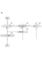
- step S21 the processor 52 functions as the external force acquisition unit 60 and acquires the external force EF applied to the movable element of the robot 12. Specifically, the processor 52 acquires detection data from the first force sensor 42, the second force sensor 44, the third force sensor 46, and the fourth force sensor 48, and responds from the detection data.
- the external force torques ET 1 , ET 2 , ET 3 , and ET 4 are calculated by subtracting the components of the internal force, respectively.
- the processor 52 acquires the external force EF applied to the robot 12 based on the external force torques ET 1 , ET 2 , ET 3 , and ET 4.
- the external force EF applied to a predetermined portion (for example, the end effector 24) of the robot 12 acts on all the joint axes 28, 32, 36, 40 located on the proximal end side of the predetermined portion. become.
- the external force torque ET acting on the joint axes 28, 32, 36, and 40 when an external force EF of a predetermined size and direction is applied to a predetermined part of the robot 12 is a kinematic equation, an experimental method. , Or it can be known from simulations and the like.
- the portion of the robot 12 to which the external force EF is applied and the magnitude and direction of the external force EF can be estimated from the external force torque acting on the joint shafts 28, 32, 36, and 40.
- the processor 52 uses any of the movable elements of the robot 12 (swivel body 16, lower arm 18, upper arm 20, wrist 22, or wrist 22). It is specified whether the external force EF is applied to the end effector 24), and the magnitude and direction of the external force EF are acquired.
- step S22 the processor 52 acquires the movement information of the movable element identified that the external force EF has been applied in the latest step S21. If it is specified in the latest step S21 that an external force EF is applied to the upper arm portion 20 of the robot 12, the processor 52 functions as the speed acquisition unit 64 described above, and the movement speed of the upper arm portion 20 is used as movement information. Acquire MV U (or acceleration).
- This movement speed MV U is the movement speed MV of the upper arm portion 20 in the robot coordinate system (or the world coordinate system that defines the three-dimensional space of the work cell) set for the robot 12 to control the robot 12. It may be U, or it may be the moving speed (that is, rotation speed) MV U of the upper arm portion 20 with respect to the lower arm portion 18 connected to the proximal end side of the upper arm portion 20.
- the processor 52 is a position feedback FB from the rotation detectors of the servomotors 26, 30 and 34 arranged on the proximal end side of the upper arm portion 20, a command to the servomotors 26, 30 and 34, or a work program.
- the movement speed MV U can be acquired based on the information (command statement, etc.) included in the WP.
- the processor 52 functions as a movement direction acquisition unit 62 described above, based on the position feedback FB, command or work program WP, it acquires the moving direction MD U of the upper arm portion 20.
- the moving speed MD U may be a moving direction MD U of the upper arm portion 20 in the above robot coordinate system (or the world coordinate system), or, the lower arm portion connected to the base end side of the upper arm 20 moving direction of the upper arm portion 20 for 18 (that is, rotation direction) may be MD U.
- step S23 the processor 52 functions as the first condition determination unit 66, and whether or not the first condition that an external force FT exceeding a predetermined threshold value ⁇ (first threshold value) is applied to the movable element is satisfied.
- a predetermined threshold value ⁇ first threshold value
- the thresholds of external force EFs ⁇ 1 , ⁇ 2 , ⁇ 3 , ⁇ 4 and ⁇ 5 that differ from each other with respect to the swivel body 16, the lower arm 18, the upper arm 20, the wrist 22, and the end effector 24 as movable elements. are set respectively.
- the processor 52 when an external force EF U opposite direction MD U 'exceeds the threshold value [delta] 3 to the moving direction MD U of the upper arm portion 20 determines that the first condition is satisfied (i.e., YES) ..
- processor 52 determines whether or not the magnitude exceeds the threshold value ⁇ 3.
- the processor 52 determines, is opposite to the external force EF U direction the moving direction MD U of, and, if the size exceeds a threshold value [delta] 3, the first condition is satisfied (i.e., YES) and.
- the processor 52 when the angle theta between the external force EF U direction and the moving direction MD U of a predetermined range (e.g., theta> range of 90 °), moving direction of the external force torque ET n It may be determined that the direction is opposite to the direction MD n. Or, the processor 52, when the inner product IP of a unit vector of the external force EF U unit vectors as the moving direction MD U of a predetermined range (e.g., range of IP ⁇ 0), movement direction of the external force torque ET n It may be determined that the direction is opposite to the direction MD n.
- a predetermined range e.g., theta> range of 90 °
- moving direction of the external force torque ET n It may be determined that the direction is opposite to the direction MD n.
- the processor 52 determines whether exceeds the threshold value [delta] 3 it may be determined to be YES if the ingredients EF U 'exceeds the threshold value [delta] 3. If the processor 52 determines YES in step S23, the processor 52 proceeds to step S24, while if it determines NO, the processor 52 proceeds to step S9.
- step S23 the processor 52 satisfies the first condition (YES) when the magnitude of the acquired external force EF exceeds the threshold value ⁇ without considering the direction of the external force EF applied to the movable element. ) May be determined. Further, instead of setting the threshold values ⁇ 1 , ⁇ 2 , ⁇ 3 , ⁇ 4 and ⁇ 5 for each of the plurality of movable elements, a constant threshold value ⁇ 0 may be set for all the movable elements.
- step S24 the processor 52 functions as the second condition determination unit 68, and determines whether or not the second condition that the movable element to which the external force EF is applied is moving is satisfied. Assuming that the external force EF is applied to the upper arm portion 20 in the latest step S21, the processor 52 previously determines the moving speed MV U (or acceleration) of the upper arm portion 20 acquired in the latest step S22. When the predetermined threshold value ⁇ (second threshold value) is exceeded, it is determined that the second condition is satisfied (that is, YES).
- ⁇ second threshold value
- the processor 52 can also determine whether or not the second condition is satisfied without comparing the moving speed MV U with the threshold value ⁇ . For example, in the processor 52, when the value of the position feedback FB from the rotation detector provided in the third servomotor 34 fluctuates, the upper arm portion 20 is moving (that is, the second condition is satisfied). You may judge.
- the processor 52 may determine whether or not the upper arm portion 20 is moving from a command to the third servomotor 34, a command statement included in the work program WP, or the like. If the processor 52 determines YES in step S24, the processor 52 proceeds to step S10 and stops the operation of the robot 12, while if it determines NO, the processor 52 proceeds to step S9. In this way, the processor 52 loops steps S21 to S24 and S9 until it determines YES in step S9 or S24.
- the processor 52 acquires the external force EF applied to the swivel body 16, the lower arm portion 18, the upper arm portion 20, the wrist portion 22, or the end effector 24 as movable elements.
- the robot 12 is stopped in step S10. ..
- the processor 52 continues the operation of the robot 12 until it is determined as YES in step S9. According to this configuration, as in the above-described embodiment, it is possible to prevent the efficiency of the work from being lowered while ensuring the safety of the work.
- a plurality of force sensors 42, 44, 46, and 48 are provided, but the robot system 10 is not limited to this, and one force sensor capable of detecting forces in a plurality of directions may be provided. .. Such an embodiment is shown in FIGS. 5 and 6.
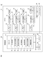
- the robot system 80 shown in FIGS. 5 and 6 is different from the robot system 10 described above in the following configurations. That is, the robot system 80 includes a force sensor 82 instead of the force sensors 42, 44, 46 and 48 described above.
- the force sensor 82 is, for example, a 6-axis force sensor having a plurality of strain gauges (not shown), and is inserted between the robot base 14 and a fixing plate 84 fixed to the floor A of the work cell. Has been done. When a force acts on the force sensor 82, the strain gauge of the force sensor 82 transmits detection data corresponding to the applied force to the control device 50.
- the processor 52 functions as an external force acquisition unit 60, and acquires the external force EF applied to the robot 12 based on the detection data received from the force sensor 82 via the I / O interface 56. Specifically, the processor 52 uses the force in the x-axis, y-axis, and z-axis directions of the sensor coordinate system SC set in the force sensor 82 based on the detection data from the force sensor 82, and around the x-axis. Find the force in the 6-axis direction with the torque around the y-axis and around the z-axis.
- the processor 52 obtains a component of an internal force acting on the force sensor 82 due to the mass of the robot 12 and the inertial force generated by the operation of the robot 12 from the force in the 6-axis direction of the sensor coordinate system SC. Subtract each to obtain the external force component in the 6-axis direction.
- the external force component acting in the 6-axis direction of the sensor coordinate system SC when an external force EF of a predetermined magnitude and direction is applied to a predetermined part of the robot 12 is a kinematic equation, an experimental method, or an experimental method. It can be known from simulations and the like. In other words, the portion of the robot 12 to which the external force EF is applied and the magnitude and direction of the external force EF can be estimated from the external force component in the 6-axis direction of the sensor coordinate system SC.
- the processor 52 uses any of the movable elements of the robot 12 (swivel body 16, lower arm 18, upper arm 20, wrist 22, or end effector 24) based on the external force component in the 6-axis direction of the sensor coordinate system SC. ), And the magnitude and direction of the external force EF can be obtained.
- the processor 52 of the control device 50 controls the robot 12 by executing the robot control flow shown in FIG. In this case, in step S2, the processor 52 acquires the external force EF based on the detection data of the force sensor 82 as described above.
- the configurations of the robot systems 10 and 80 can be combined.
- the force sensor 82 of the robot system 80 may be applied to the robot system 10, and the processor 52 of the robot system 10 may execute the flow shown in FIG. 3 and the flow shown in FIG. 4 in parallel.
- the control device 50 of the robot system 10 may have a first processor 52A that executes the flow shown in FIG. 3 and a second processor 52B that executes the flow shown in FIG.
- the robot system 90 differs from the above-mentioned robot system 10 in the following configurations. That is, in the robot system 90, a handle 92, a hand guide sensor 94, and an operation mode changeover switch 96 are further provided.
- the handle 92 is provided on the base portion 24a of the end effector 24, and has a shape that is ergonomically easy for an operator to grasp.
- the hand guide sensor 94 is, for example, a 6-axis force sensor, which is inserted between the handle 92 and the base portion 24a. The hand guide sensor 94 detects the operating force HF applied to the handle 92 by the worker and transmits the detection data to the control device 50.
- the operation mode changeover switch 96 has a physical changeover switch, a push button, a touch sensor, and the like, and is provided on the handle 92.
- the operation mode changeover switch 96 switches the operation mode of the robot 12 between the automatic operation mode and the hand guide operation mode.
- the automatic operation mode is an operation mode in which the robot 12 automatically operates according to the work program WP to perform a predetermined work as in step S1 described above.
- the hand guide operation mode is an operation mode in which the robot 12 is manually operated according to the operating force HF applied to the handle 92 by the worker, as will be described later.
- the operation mode changeover switch 96 When the operation mode changeover switch 96 is turned on, the operation mode changeover switch 96 transmits a hand guide signal “ON” (or “1”) to the control device 50.
- step S31 the processor 52 determines whether or not the hand guide signal is turned "ON".
- step S32 the processor 52 shifts the operation mode of the robot 12 to the hand-guided operation mode, and executes the control flow of the hand-guided operation mode. This step S32 will be described later.
- step S33 the processor 52 determines whether or not the above-mentioned automatic work start command has been received from the operator, the host controller, or the computer program (for example, the above-mentioned work program WP).
- the processor 52 receives the automatic work start command, it determines YES and proceeds to step S34, while when it has not received the automatic work start command, it determines NO and proceeds to step S35.
- step S34 the processor 52 shifts the operation mode of the robot 12 to the automatic operation mode, and executes the control flow of the automatic operation mode. This step S34 will be described later.
- step S35 the processor 52 determines whether or not the shutdown command for terminating the operation of the control device 50 has been accepted.
- the processor 52 determines YES, terminates the operation of the control device 50, and thus terminates the flow shown in FIG.
- the processor 52 determines NO and returns to step S31.
- step S32 The control flow of the hand guide operation mode in step S32 will be described with reference to FIG. In the flow shown in FIG. 10, the same process as in FIG. 3 is assigned the same step number, and duplicate description will be omitted.
- the processor 52 executes steps S2 and S3 described above.
- step S41 the processor 52 acquires the operating force HF. Specifically, the processor 52 acquires the detection data of the operating force HF from the hand guide sensor 94. Then, the processor 52 acquires the magnitude and direction of the operating force HF applied to the handle 92 based on the detection data of the hand guide sensor 94 and the position and posture data of the end effector 24 at this time.
- step S42 the processor 52 determines whether or not the magnitude of the operating force HF acquired in the latest step S41 exceeds a predetermined threshold value ⁇ (HF ⁇ ⁇ ).
- a predetermined threshold value ⁇ HF ⁇ ⁇
- the processor 52 determines that the magnitude of the operating force HF exceeds the threshold value ⁇ (that is, YES)
- the processor 52 proceeds to step S43, while the magnitude of the operating force HF does not exceed the threshold value ⁇ (that is, NO). If it is determined, the process proceeds to step S44.
- step S43 the processor 52 operates the robot 12 so as to move the end effector 24 according to the operating force HF. Specifically, the processor 52 transmits a command to the servomotors 26, 30, 34, and 38, and moves the end effector 24 in the direction of the operating force HF by a predetermined distance d (for example, 10 cm).
- d for example, 10 cm
- the processor 52 may change the distance d to be moved in this step S43 according to the magnitude of the operating force HF acquired in the latest step S41 (for example, the larger the operating force HF, the greater the distance d. Enlarge).
- the processor 52 sequentially executes steps S4 to S8 and S10 similar to the flow of FIG.
- the processor 52 sets the value of the threshold value ⁇ n to be referred to when executing step S5 in FIG. 10 to ⁇ n_1 .
- step S44 the processor 52 determines whether or not the shutdown command has been accepted, as in step S35 described above. If the processor 52 determines YES, the operation of the control device 50 is terminated, and thus the flow shown in FIG. 9 is terminated. On the other hand, if the processor 52 determines NO, the processor 52 proceeds to step S45.
- step S45 the processor 52 determines whether or not the hand guide signal is set to "OFF” (or “0"). Specifically, when the worker turns off the operation mode changeover switch 96, the operation mode changeover switch 96 transmits a hand guide signal “OFF” (or “0”) to the control device 50. When the hand guide signal becomes “OFF”, the processor 52 determines YES and proceeds to step S33 in FIG. On the other hand, when the hand guide signal is "ON”, the processor 52 determines NO and returns to step S41 in FIG.
- the processor 52 monitors whether or not the first condition and the second condition are satisfied for each of the joint axes 28, 32, 36, and 40 during the hand-guided operation of operating the robot 12 according to the operating force HF. , The operation of the robot 12 is stopped or continued accordingly. In the flow shown in FIG. 10, the processor 52 ends the flow shown in FIG. 10 without executing the above-mentioned step S11 after step S10.
- step S34 the control flow of the automatic operation mode in step S34 will be described with reference to FIG. In the flow shown in FIG. 11, the same process as in FIGS. 3 and 9 is assigned the same step number, and duplicate description will be omitted.
- the processor 52 sequentially executes the above-mentioned steps S1 to S11 in the same manner as in the flow of FIG.
- the processor 52 the value of the threshold alpha n to be referred to when executing the step S5 in FIG. 11, it is set to ⁇ n_2 ( ⁇ n_1). Then, when the processor 52 determines NO in step S9, the processor 52 executes the above-mentioned step S31, and when it determines YES, the processor 52 proceeds to step S32 in FIG. 9, while when it determines NO, in FIG. Return to step S4 of.
- the processor 52 executes the hand-guided operation mode in step S32, the threshold value ⁇ n used for determining the first condition in step S5 is set to the value ⁇ n_1. Meanwhile, when performing the automatic operation mode in step S34, the threshold alpha n used for the determination of the first condition at step S5, is set to a value ⁇ n_2 ( ⁇ n_1). Therefore, the processor 52 functions as a threshold value setting unit 98 (FIG. 8) that changes the threshold value ⁇ n according to the operation mode of the robot 12.
- the robot 12 is manually operated according to the force intentionally applied to the handle 92 by the operator.
- the threshold alpha n_1 used in such a hand-guided operation mode by setting larger than the threshold value alpha n_2 used in automatic operation mode, from being a robot 12 is stopped by the force operator is intentionally added, avoidance can do.
- the force sensor 82 can be applied instead of the force sensors 42, 44, 46 and 48.
- steps S21 to S24 in FIG. 4 can be applied to the flows shown in FIGS. 10 and 11.
- the above-mentioned force sensors 42, 44, 46 and 48 may be arranged so as to detect the torque applied to the output shafts of the servomotors 26, 30, 34 and 38.
- the above-mentioned force sensor 82 may be provided at any position (for example, the lower arm portion 18) of the robot 12. Further, in the above-described embodiment, four joint shafts 28, 32, 36 and 40, four servomotors 26, 30, 34 and 38, and four force sensors 42, 44, 46 and 48 are provided. I mentioned the case where it is. However, the number of joint shafts, servomotors, and force sensors is not limited to this, and may be any positive number other than 4.
- the robot 12 is not limited to a vertical articulated robot, and may be any type of robot having a movable element such as a horizontal articulated robot or a parallel link robot.
- Robot system 12 Robot 50
- Control device 52 Processor 60 External force acquisition unit 62 Movement direction acquisition unit 64 Speed acquisition unit 66 First condition judgment unit 68 Second condition judgment unit 70
Landscapes
- Engineering & Computer Science (AREA)
- Robotics (AREA)
- Mechanical Engineering (AREA)
- Human Computer Interaction (AREA)
- Manipulator (AREA)
Abstract
Description
12 ロボット
50 制御装置
52 プロセッサ
60 外力取得部
62 移動方向取得部
64 速度取得部
66 第1条件判定部
68 第2条件判定部
70 動作制御部
Claims (10)
- 可動要素を有するロボットの制御装置であって、
前記ロボットが動作しているときに前記可動要素に加えられた外力を取得する外力取得部と、
予め定めた第1の閾値を超えた前記外力が前記可動要素に加えられたという第1条件を満たすか否かを判定する第1条件判定部と、
前記可動要素が移動しているという第2条件を満たすか否かを判定する第2条件判定部と、
前記第1条件及び前記第2条件の双方が満たされたときは前記ロボットの動作を停止する一方、前記第1条件及び前記第2条件の少なくとも一方が満たされていないときは前記ロボットの動作を継続させる動作制御部と、を備える、制御装置。 - 前記可動要素の移動速度を取得する速度取得部をさらに備え、
前記第2条件判定部は、前記移動速度が予め定めた第2の閾値を超えたときに、前記第2条件を満たすと判定する、請求項1に記載の制御装置。 - 前記可動要素の移動方向を取得する移動方向取得部をさらに備え、
前記第1条件判定部は、前記移動方向とは反対の方向の前記外力が前記第1の閾値を超えたときに、前記第1条件を満たすと判定する、請求項1又は2に記載の制御装置。 - 前記ロボットの運転モードに応じて前記第1の閾値を変更する閾値設定部をさらに備える、請求項1~3のいずれか1項に記載の制御装置。
- 前記動作制御部は、前記ロボットの動作を停止させた後に該ロボットに退避動作を実行させる、請求項1~4のいずれか1項に記載の制御装置。
- 前記ロボットは、複数の前記可動要素を備え、
前記第1条件判定部は、1つの前記可動要素について前記第1条件を満たすか否かを判定し、
前記第2条件判定部は、前記1つの可動要素について前記第2条件を満たすか否かを判定する、請求項1~5のいずれか1項に記載の制御装置。 - 前記可動要素は、前記ロボットの関節軸であり、
前記外力取得部は、前記外力として、前記関節軸に加えられた外力トルクを取得する、請求項1~6のいずれか1項に記載の制御装置。 - ロボットと、
前記ロボットを制御する、請求項1~7のいずれか1項に記載の制御装置と、を備える、ロボットシステム。 - 前記可動要素に掛かる力を検出する力センサをさらに備え、
前記外力取得部は、前記力センサの検出データに基づいて前記外力を取得する、請求項8に記載のロボットシステム。 - 可動要素を有するロボットの制御方法であって、
前記ロボットが動作しているときに前記可動要素に加えられた外力を取得し、
予め定めた第1の閾値を超えた前記外力が前記可動要素に加えられたという第1条件を満たすか否かを判定し、
前記可動要素が移動しているという第2条件を満たすか否かを判定し、
前記第1条件及び前記第2条件の双方が満たされたときは前記ロボットの動作を停止する一方、前記第1条件及び前記第2条件の少なくとも一方が満たされていないときは前記ロボットの動作を継続する、制御方法。
Priority Applications (4)
| Application Number | Priority Date | Filing Date | Title |
|---|---|---|---|
| US17/905,825 US12311558B2 (en) | 2020-03-12 | 2021-03-05 | Robot control device, robot system, and robot control method |
| DE112021001568.0T DE112021001568T5 (de) | 2020-03-12 | 2021-03-05 | Robotersteuervorrichtung, Robotersystem und Robotersteuerverfahren |
| CN202180020335.8A CN115243846B (zh) | 2020-03-12 | 2021-03-05 | 机器人的控制装置、机器人系统、机器人控制方法 |
| JP2022507154A JP7556938B2 (ja) | 2020-03-12 | 2021-03-05 | ロボットの制御装置、ロボットシステム、ロボット制御方法 |
Applications Claiming Priority (2)
| Application Number | Priority Date | Filing Date | Title |
|---|---|---|---|
| JP2020-043420 | 2020-03-12 | ||
| JP2020043420 | 2020-03-12 |
Publications (1)
| Publication Number | Publication Date |
|---|---|
| WO2021182356A1 true WO2021182356A1 (ja) | 2021-09-16 |
Family
ID=77671709
Family Applications (1)
| Application Number | Title | Priority Date | Filing Date |
|---|---|---|---|
| PCT/JP2021/008814 Ceased WO2021182356A1 (ja) | 2020-03-12 | 2021-03-05 | ロボットの制御装置、ロボットシステム、ロボット制御方法 |
Country Status (5)
| Country | Link |
|---|---|
| US (1) | US12311558B2 (ja) |
| JP (1) | JP7556938B2 (ja) |
| CN (1) | CN115243846B (ja) |
| DE (1) | DE112021001568T5 (ja) |
| WO (1) | WO2021182356A1 (ja) |
Families Citing this family (2)
| Publication number | Priority date | Publication date | Assignee | Title |
|---|---|---|---|---|
| DE112022006750T5 (de) * | 2022-06-27 | 2025-01-16 | Fanuc Corporation | Robotersteuer- bzw. -regelvorrichtung und Robotersystem |
| JP2024164671A (ja) * | 2023-05-15 | 2024-11-27 | 株式会社不二越 | 協働ロボットシステム |
Citations (7)
| Publication number | Priority date | Publication date | Assignee | Title |
|---|---|---|---|---|
| JP2003025272A (ja) * | 2001-05-08 | 2003-01-29 | Mitsubishi Electric Corp | ロボット制御装置 |
| JP2005342858A (ja) * | 2004-06-04 | 2005-12-15 | Toshiba Mach Co Ltd | 産業用ロボットの衝突検出方法および衝突検出装置 |
| JP2010228028A (ja) * | 2009-03-26 | 2010-10-14 | Nec Corp | ロボットアーム、ロボットアームの接触検知方法、及び、ロボットアームを備えた装置 |
| JP2016064474A (ja) * | 2014-09-25 | 2016-04-28 | ファナック株式会社 | 人間協調ロボットシステム |
| JP2016132080A (ja) * | 2015-01-21 | 2016-07-25 | ファナック株式会社 | ロボットに加わる外力に基づいてロボットを制御するロボット制御装置、およびロボットシステム |
| JP2017077608A (ja) * | 2015-10-21 | 2017-04-27 | ファナック株式会社 | ロボットの安全監視装置 |
| JP2020032488A (ja) * | 2018-08-30 | 2020-03-05 | ファナック株式会社 | 人間協調ロボットシステム |
Family Cites Families (9)
| Publication number | Priority date | Publication date | Assignee | Title |
|---|---|---|---|---|
| JP4938118B2 (ja) * | 2010-08-17 | 2012-05-23 | ファナック株式会社 | 人間協調ロボットシステム |
| JP5905443B2 (ja) * | 2013-12-25 | 2016-04-20 | ファナック株式会社 | 人協調型産業用ロボットの外力判定方法および外力判定装置 |
| JP6100727B2 (ja) | 2014-04-09 | 2017-03-22 | ファナック株式会社 | リードスルー機能を有する人協調型産業用ロボット |
| DE102014114234B4 (de) * | 2014-09-30 | 2020-06-25 | Kastanienbaum GmbH | Verfahren und Vorrichtung zur Steuerung/Regelung eines Roboter-Manipulators |
| JP6423815B2 (ja) * | 2016-03-30 | 2018-11-14 | ファナック株式会社 | 人協働型のロボットシステム |
| DE102017106791A1 (de) * | 2017-03-29 | 2018-10-04 | Kuka Deutschland Gmbh | Überwachungsverfahren und Überwachungssystem |
| JP6690626B2 (ja) * | 2017-10-31 | 2020-04-28 | 株式会社安川電機 | ロボットシステムおよびロボットの退避方法 |
| JP7172277B2 (ja) * | 2018-08-21 | 2022-11-16 | セイコーエプソン株式会社 | 制御装置及びロボットシステム |
| JP7211007B2 (ja) * | 2018-10-30 | 2023-01-24 | セイコーエプソン株式会社 | 制御装置、ロボットシステムおよび制御方法 |
-
2021
- 2021-03-05 CN CN202180020335.8A patent/CN115243846B/zh active Active
- 2021-03-05 JP JP2022507154A patent/JP7556938B2/ja active Active
- 2021-03-05 US US17/905,825 patent/US12311558B2/en active Active
- 2021-03-05 DE DE112021001568.0T patent/DE112021001568T5/de active Pending
- 2021-03-05 WO PCT/JP2021/008814 patent/WO2021182356A1/ja not_active Ceased
Patent Citations (7)
| Publication number | Priority date | Publication date | Assignee | Title |
|---|---|---|---|---|
| JP2003025272A (ja) * | 2001-05-08 | 2003-01-29 | Mitsubishi Electric Corp | ロボット制御装置 |
| JP2005342858A (ja) * | 2004-06-04 | 2005-12-15 | Toshiba Mach Co Ltd | 産業用ロボットの衝突検出方法および衝突検出装置 |
| JP2010228028A (ja) * | 2009-03-26 | 2010-10-14 | Nec Corp | ロボットアーム、ロボットアームの接触検知方法、及び、ロボットアームを備えた装置 |
| JP2016064474A (ja) * | 2014-09-25 | 2016-04-28 | ファナック株式会社 | 人間協調ロボットシステム |
| JP2016132080A (ja) * | 2015-01-21 | 2016-07-25 | ファナック株式会社 | ロボットに加わる外力に基づいてロボットを制御するロボット制御装置、およびロボットシステム |
| JP2017077608A (ja) * | 2015-10-21 | 2017-04-27 | ファナック株式会社 | ロボットの安全監視装置 |
| JP2020032488A (ja) * | 2018-08-30 | 2020-03-05 | ファナック株式会社 | 人間協調ロボットシステム |
Also Published As
| Publication number | Publication date |
|---|---|
| JP7556938B2 (ja) | 2024-09-26 |
| CN115243846A (zh) | 2022-10-25 |
| US20230120261A1 (en) | 2023-04-20 |
| CN115243846B (zh) | 2025-12-26 |
| JPWO2021182356A1 (ja) | 2021-09-16 |
| US12311558B2 (en) | 2025-05-27 |
| DE112021001568T5 (de) | 2022-12-29 |
Similar Documents
| Publication | Publication Date | Title |
|---|---|---|
| JP7275488B2 (ja) | ロボットシステム | |
| US9821459B2 (en) | Multi-joint robot having function for repositioning arm | |
| CN105583826B (zh) | 工业机器人和用于控制工业机器人的方法 | |
| US11173614B2 (en) | Control apparatus and robot system | |
| US11717964B2 (en) | Control device for robot that works collaboratively with people | |
| US12011825B2 (en) | Device, method and program for estimating weight and position of gravity center of load by using robot | |
| US11660742B2 (en) | Teaching method and robot system | |
| CN107803847A (zh) | 人机协调型机器人 | |
| US12064881B2 (en) | Robot controlling device | |
| KR20190079322A (ko) | 로봇 제어 시스템 | |
| US20220134571A1 (en) | Display Control Method, Display Program, And Robot System | |
| WO2021182356A1 (ja) | ロボットの制御装置、ロボットシステム、ロボット制御方法 | |
| CN117412840A (zh) | 具有碰撞检测功能的协作机器人及协作机器人的碰撞检测方法 | |
| KR101968751B1 (ko) | 충돌 감지 장치, 그를 갖는 엔드 이펙터, 로봇 및 그를 이용한 충돌 감지 방법 | |
| KR102834774B1 (ko) | 로봇 교시 시스템 및 방법 | |
| US12109702B2 (en) | Method of adjusting force control parameter, robot system, and force control parameter adjustment program | |
| JP7384005B2 (ja) | 制御方法およびロボットシステム | |
| US20240316772A1 (en) | Control Method, Robot System, And Non-Transitory Computer-Readable Storage Medium Storing Program | |
| JP2024164671A (ja) | 協働ロボットシステム | |
| CN118715097A (zh) | 机器人控制装置 |
Legal Events
| Date | Code | Title | Description |
|---|---|---|---|
| 121 | Ep: the epo has been informed by wipo that ep was designated in this application |
Ref document number: 21767683 Country of ref document: EP Kind code of ref document: A1 |
|
| ENP | Entry into the national phase |
Ref document number: 2022507154 Country of ref document: JP Kind code of ref document: A |
|
| 122 | Ep: pct application non-entry in european phase |
Ref document number: 21767683 Country of ref document: EP Kind code of ref document: A1 |
|
| WWG | Wipo information: grant in national office |
Ref document number: 17905825 Country of ref document: US |