WO2021182027A1 - グロメットおよびワイヤハーネス - Google Patents
グロメットおよびワイヤハーネス Download PDFInfo
- Publication number
- WO2021182027A1 WO2021182027A1 PCT/JP2021/005615 JP2021005615W WO2021182027A1 WO 2021182027 A1 WO2021182027 A1 WO 2021182027A1 JP 2021005615 W JP2021005615 W JP 2021005615W WO 2021182027 A1 WO2021182027 A1 WO 2021182027A1
- Authority
- WO
- WIPO (PCT)
- Prior art keywords
- grommet
- inner member
- holding
- tubular
- lid
- Prior art date
- Legal status (The legal status is an assumption and is not a legal conclusion. Google has not performed a legal analysis and makes no representation as to the accuracy of the status listed.)
- Ceased
Links
Images

Classifications
-
- B—PERFORMING OPERATIONS; TRANSPORTING
- B60—VEHICLES IN GENERAL
- B60R—VEHICLES, VEHICLE FITTINGS, OR VEHICLE PARTS, NOT OTHERWISE PROVIDED FOR
- B60R16/00—Electric or fluid circuits specially adapted for vehicles and not otherwise provided for; Arrangement of elements of electric or fluid circuits specially adapted for vehicles and not otherwise provided for
- B60R16/02—Electric or fluid circuits specially adapted for vehicles and not otherwise provided for; Arrangement of elements of electric or fluid circuits specially adapted for vehicles and not otherwise provided for electric constitutive elements
-
- H—ELECTRICITY
- H01—ELECTRIC ELEMENTS
- H01B—CABLES; CONDUCTORS; INSULATORS; SELECTION OF MATERIALS FOR THEIR CONDUCTIVE, INSULATING OR DIELECTRIC PROPERTIES
- H01B17/00—Insulators or insulating bodies characterised by their form
- H01B17/56—Insulating bodies
- H01B17/58—Tubes, sleeves, beads, or bobbins through which the conductor passes
-
- H—ELECTRICITY
- H01—ELECTRIC ELEMENTS
- H01B—CABLES; CONDUCTORS; INSULATORS; SELECTION OF MATERIALS FOR THEIR CONDUCTIVE, INSULATING OR DIELECTRIC PROPERTIES
- H01B7/00—Insulated conductors or cables characterised by their form
-
- H—ELECTRICITY
- H02—GENERATION; CONVERSION OR DISTRIBUTION OF ELECTRIC POWER
- H02G—INSTALLATION OF ELECTRIC CABLES OR LINES, OR OF COMBINED OPTICAL AND ELECTRIC CABLES OR LINES
- H02G3/00—Installations of electric cables or lines or protective tubing therefor in or on buildings, equivalent structures or vehicles
- H02G3/22—Installations of cables or lines through walls, floors or ceilings, e.g. into buildings
Definitions
- This disclosure relates to grommets and wire harnesses.
- a grommet is attached to the wire harness, and the grommet is attached to a through hole formed in a panel partitioning the inside and outside of the automobile. ..
- the grommet closes the through hole to prevent water, noise, etc. from entering the vehicle interior from the outside of the vehicle interior.
- the present disclosure has been made in the background of the above-mentioned circumstances, and the problem to be solved is to provide a grommet and a wire harness having a novel structure capable of improving soundproofing with a small number of parts. be.
- the grommet of the present disclosure can be attached to an attached body having a first surface, a second surface facing the first surface, and a through hole penetrating the first surface and the second surface.
- An annular inner member through which the electric wire member can penetrate an annular inner member capable of penetrating the through hole, a first grommet member held by the inner member, and a second grommet member held by the inner member.
- the first grommet member communicates the first grommet member covering the through hole, the first cylinder portion protruding from the first lid portion, and the second grommet member and the first cylinder portion.
- the second grommet member having a first opening includes a second lid portion that covers the first opening, a second tubular portion that protrudes from the second lid portion, the first grommet member, and the above.
- the inner member has a second opening for communicating with the second cylinder portion, and the inner member includes a first holding portion for holding the first grommet member, a second holding portion for holding the second grommet member, and a second holding portion. It has a locking portion that can be locked to the second surface of the attached body, and the first grommet member and the second grommet member can be attached to the attached body via the inner member. It is a grommet.
- the wire harness of the present disclosure is a wire harness including an electric wire member and the grommet through which the electric wire member penetrates.
- FIG. 1 is an overall perspective view showing a grommet and a wire harness according to the first embodiment of the present disclosure.
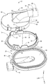
- FIG. 2 is an exploded perspective view of the grommet shown in FIG.
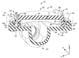
- FIG. 3 is an enlarged vertical cross-sectional view showing an enlarged view of the III-III cross section in FIG.
- the grommet of this disclosure is (1)
- the wire member can be attached to an attached body having a first surface, a second surface facing the first surface, and a through hole penetrating the first surface and the second surface.
- a penetrating grommet including an annular inner member capable of penetrating the through hole, a first grommet member held by the inner member, and a second grommet member held by the inner member.
- the first grommet member is a first opening that communicates a first lid portion that covers the through hole, a first cylinder portion that protrudes from the first lid portion, and the second grommet member and the first cylinder portion.
- the second grommet member has a portion, and the second grommet member includes a second lid portion that covers the first opening, a second cylinder portion that protrudes from the second lid portion, the first grommet member, and the second cylinder.
- the inner member has a second opening for communicating with the portion, and the inner member includes a first holding portion for holding the first grommet member, a second holding portion for holding the second grommet member, and the attached portion.
- the first grommet member and the second grommet member have a locking portion that can be locked to the second surface of the body, and the first grommet member and the second grommet member are grommets that can be attached to the attached body via the inner member. ..
- the first opening of the first grommet member is covered with the second lid portion of the second grommet member. Therefore, the noise propagated from the first opening of the first grommet member can be advantageously blocked or reduced, and the soundproofing property of the grommet can be improved.
- the first grommet member and the second grommet member are held by a single inner member, and by locking the locking portion of the inner member to the peripheral edge of the through hole of the attached body, the first grommet member is held. The member and the second grommet member can be fixed to the attached body at the same time.
- the attached body includes a panel that separates the engine room from the vehicle interior, a panel that separates the vehicle interior from the vehicle interior, and the like.
- the electric wire member includes not only electric wires and optical cables but also those having an exterior material on them.
- the plurality of locking portions are arranged apart from each other in the circumferential direction of the inner member, and the second holding portion is located between the plurality of locking portions adjacent to each other in the circumferential direction. It is preferably arranged.
- a plurality of locking portions of the inner member can be locked to a plurality of portions separated from each other in the circumferential direction of the through hole of the attached body, and stable fixing of the inner member to the attached body can be realized.
- the second holding portion of the inner member is provided between the locking portions adjacent to each other in the circumferential direction, the holding of the second grommet member by the inner member can be stably realized, and the entire grommet is covered. A stable fixed state to the mounting body can be realized.
- the second lid portion has a tubular shape that projects from the peripheral edge of the first wall portion toward the first lid portion and a first wall that faces the first lid portion in the central axis direction of the inner member.
- the inner member has a tubular tubular portion that surrounds the second wall of the second lid portion, and the first holding portion is one end portion of the tubular portion. It is preferable that the locking portion and the second holding portion are provided on the tubular portion.
- the inner member has a tubular portion that surrounds the second wall of the second lid portion of the second grommet member, and the inner member has (i) a locking portion for the through hole of the attached body and (ii) a first.
- the first holding portion for holding the 1 grommet member and the second holding portion for holding the (iii) second grommet member can be integrally provided in the tubular portion to further reduce the number of parts of the grommet. be able to.
- a locking portion for the through hole of the attached body and (iii) a second holding portion for holding the second grommet member are provided on the same circumference of the tubular portion, whereby the grommet is provided. Can be advantageously realized in a compact size.
- the locking portion is an elastic projectile that protrudes from the tubular portion and is elastically deformable in a direction approaching the central axis of the inner member, and is the second lid portion.
- the second wall of the above has a recess that allows elastic deformation of the elastic projectile. Since the elastic deformation of the elastic protrusion is allowed by the recess provided in the second wall of the second lid portion of the second grommet member, the elastic protrusion is used when the grommet is mounted in the through hole of the attached body. This is because the elastic deformation of the piece becomes easy, and the workability of attaching the grommet to the attached body can be improved.
- the thickness of the first wall is preferably thicker than the thickness of the second wall.
- the thickness dimension of the first wall facing the first lid portion of the first grommet member in the central axis direction of the inner member is increased, so that the attached body is attached. This is because the noise transmitted from the first lid portion covering the through hole can be advantageously reduced or blocked by the first wall of the second grommet member.
- the first grommet member can be brought into close contact with the first surface of the attached body by being sandwiched between the locking portion and the first holding portion. By sandwiching the peripheral edge of the through hole of the attached body between the first holding portion and the locking portion of the inner member, the first grommet member and the second grommet member are stabilized via the inner member. This is because it is fixed to the attached body.
- the first lid portion of the first grommet member has a seal portion and a first holding portion accommodating recess that is farther from the seal portion than the first opening portion.
- the first holding portion accommodating recess is open toward the inner member, and the first holding portion of the inner member is accommodated in the first holding portion accommodating recess. It is preferable that the seal portion can be brought into close contact with the first surface by being sandwiched between the locking portion and the first holding portion.
- a seal portion of the first grommet member is arranged between the first holding portion and the locking portion of the inner member, and the sealing member is sandwiched between the first holding portion and the locking portion of the inner member. As a result, it is possible to further suppress water intrusion into the through hole from the first surface side of the attached body on which the first grommet member is arranged.
- the first tubular portion is formed along the first surface of the attached body. This is because the height of protrusion of the grommet to be attached from the first surface side can be advantageously suppressed, and space-saving grommet arranging that avoids interference with adjacent members is possible.
- the second tubular portion is formed along the second surface of the attached body. This is because the height of protrusion of the grommet to be attached from the second surface side can be advantageously suppressed, and space-saving grommet arranging that avoids interference with adjacent members is possible.
- the second tubular portion preferably has a protruding portion protruding from the outer surface.
- the wire harness of the present disclosure is (11) A wire harness including an electric wire and the grommet according to any one of (1) to (10) above, through which the electric wire penetrates.
- the wire harness of the present disclosure it is possible to provide a wire harness that can enjoy the above-mentioned action and effect realized by the grommet according to any one of the above (1) to (10).
- the grommet 10 according to the first embodiment of the present disclosure is exteriorized by an electric wire 12 constituting the electric wire member 11, and as shown in FIG. 3, a through hole formed in a vehicle body panel 14 which is an attached body. It is fitted to 16. That is, the grommet 10 is capable of penetrating the electric wire member 11.
- the vehicle body panel 14 has a first surface 14a which is a lower surface, a second surface 14b which faces the first surface 14a in the vertical direction, and a through hole 16 which penetrates the first surface 14a and the second surface 14b in the vertical direction. ,have.
- the grommet 10 is used in a state of being attached to a vehicle body panel 14 having a through hole 16 through which the electric wire member 11 can penetrate.
- the grommet 10 can be arranged in any direction, but the Z direction will be described as upward, the Y direction as the width direction, and the X direction as the front in the length direction. Further, for easy understanding, the electric wire member 11 (electric wire 12, the first exterior member 17a, the second exterior member 17b) and the vehicle body panel 14 are described by virtual lines. Further, for a plurality of the same members, a reference numeral may be added to only a part of the members, and the reference numeral may be omitted for the other members.
- the electric wire member 11 includes the electric wire 12, the first exterior member 17a and the second exterior member 17b that are externally attached to the electric wire 12. Then, the grommet 10 is exteriorized with respect to the electric wire 12. The first exterior member 17a and the second exterior member 17b are exteriorized over the entire length of the electric wire 12 extending outward from the grommet 10.
- the grommet 10 includes an annular inner member 18 that is locked to the vehicle body panel 14, a first grommet member 20 that is held by the inner member 18, and a second grommet member that is held by the inner member 18. 22 and.
- both the first grommet member 20 and the second grommet member 22 are formed of a rubber material such as EPDM (ethylene propylene rubber), CR (chloroprene rubber), and SI (silicon rubber).
- the inner member 18 is made of a hard synthetic resin.
- the inner member 18 has an annular shape having a through hole 24 in the center.
- the inner member 18 has a tubular portion 26 that protrudes upward (Z direction) from the edge of the through hole 24 and a lower end portion that is one end of the tubular portion 26 toward the outside in the radial direction. It has an annular first holding portion 28 that extends like a flange. On the front side (X direction) side of the first holding portion 28 in the length direction, a trapezoidal flat plate-shaped protrusion 30 projecting forward in the length direction is provided.
- the tubular portion 26 is provided with a locking portion 32 and a second holding portion 34. The locking portion 32 projects from the tubular portion 26.
- the locking portion 32 is provided at a position facing the width direction (Y direction) on the front side in the length direction of the tubular portion 26 and at the rear end portion in the length direction of the tubular portion 26. At these three locations, the tubular portion 26 extends upward and the base end side is notched in a rectangular shape in the plate thickness direction to form the notched portion 36.
- a rectangular flat plate-shaped elastic projectile that can be elastically deformed in a direction approaching the central axis 38 of the inner member 18 is projected toward the inside of the notch 36 located downward from the tip of the tubular portion 26, and is elastic.
- the locking portion 32 is composed of the projecting pieces. On the upper side of the locking portion 32, a locking projection formed so that the plate thickness increases downward is provided.
- the second holding portion 34 is provided at a position facing the width direction (Y direction) in the central portion of the tubular portion 26 in the length direction (X direction). More specifically, at these two locations, the tubular portion 26 extends upward, and the extending end portion has a second holding that extends in the circumferential direction and projects inward in a substantially triangular cross-sectional shape. A section 34 is provided. As a result, the three locking portions 32 are arranged apart from each other in the circumferential direction of the inner member 18, and the two second holding portions 34 are arranged between the locking portions 32 adjacent to each other in the circumferential direction. There is.
- the three locking portions 32 are arranged apart from each other in the circumferential direction of the inner member 18, stable fixing of the inner member 18 to the vehicle body panel 14 can be realized. Further, two second holding portions 34 are arranged between the locking portions 32 adjacent to each other in the circumferential direction. As a result, the inner member 18 can stably hold the second grommet member 22, and the entire grommet 10 can be stably fixed to the vehicle body panel 14.
- the first grommet member 20 is first connected to the disk-shaped first lid portion 40 and the inner surface (upper surface in FIG. 2) of the first lid portion 40. It has a cylindrical first tubular portion 42 that projects diagonally downward from the lid portion 40 and then extends forward. An electric wire 12 penetrates the first cylinder portion 42. Further, as shown by the broken line portion in FIG. 1, a part of the outer peripheral surface of the protruding end portion of the first tubular portion 42 (the portion located below in FIG. 1) is separated in the length direction (X direction). A pair of first fastening member holding protrusions 44, 44 extending in the circumferential direction are provided so as to project.
- the end of the first exterior member 17a exteriored by the electric wire 12 is inserted and connected to the protruding end of the first cylinder 42.
- a fastening member (not shown) such as a binding band is arranged between the pair of first fastening member holding protrusions 44, 44 of the first tubular portion 42. Then, by fastening the fastening member, the first cylinder portion 42 is sandwiched between the first exterior member 17a and the fastening member, and the first exterior member 17a is fixed to the first cylinder portion 42.
- the pair of first fastening member holding protrusions 44, 44 suppresses the fastening member from being displaced in the length direction (X direction), and can facilitate the positioning of the fastening member.
- the front end portion of the first lid portion 40 of the first grommet member 20 projects forward in the length direction (X direction) and can accommodate the protrusion 30 of the inner member 18 inside.
- a protrusion accommodating portion 48 is provided.
- an annular thick portion 52 formed to be thicker than the central portion is provided at the edge portion of the first lid portion 40 of the first grommet member 20.
- a first holding portion accommodating recess 50 that opens toward the central axis 38 of the inner member 18 is provided.
- the first opening 53 is formed by the upper end of the inner peripheral surface of the thick portion 52.
- a seal portion 54 having a V-shaped cross-sectional shape and projecting upward over the entire circumference of the first lid portion 40 is provided. That is, the first holding portion accommodating recess 50 is located inward (downward) from the seal portion 54 with respect to the first opening 53 in the central axis 38 direction (Z direction (vertical direction)) of the inner member 18. The inner member 18 is opened toward the central axis 38.
- the second grommet member 22 is connected to the disc-shaped second lid portion 56 and the inner surface of the second lid portion 56 and projects obliquely upward, and then rearwardly. It has a cylindrical second tubular portion 58 extending toward it. An electric wire 12 penetrates the second cylinder portion 58. Further, as shown in FIG. 1, a part of the outer peripheral surface of the protruding end portion of the second tubular portion 58 (the portion located above in FIG. 1) is separated from the circumference in the length direction (X direction). A pair of second fastening member holding protrusions 60, 60 extending in the direction are provided.
- the end of the second exterior member 17b exteriorized by the electric wire 12 is inserted and connected to the protruding end of the second cylinder 58.
- a fastening member (not shown) such as a binding band is arranged between the pair of second fastening member holding protrusions 60, 60 of the second cylinder portion 58. Then, by fastening the fastening member, the second cylinder portion 58 is sandwiched between the second exterior member 17b and the fastening member, and the second exterior member 17b is fixed to the second cylinder portion 58.
- the pair of second fastening member holding protrusions 60, 60 suppresses the fastening member from being displaced in the length direction (X direction), and can facilitate the positioning of the fastening member.
- a protruding portion 63 that protrudes upward in a triangular shape in a lateral view is provided at the central portion in the width direction (Y direction).
- the protruding portion 63 reinforces the connecting portion between the second lid portion 56 and the second tubular portion 58, and can also be used as a handle. That is, when the electric wire 12 or the like is passed through the second cylinder portion 58 of the second grommet member 22, the operator grips the protruding portion 63 of the second grommet member 22 to penetrate the electric wire 12 or the like through the grommet 10. Workability can be improved.
- the second lid portion 56 of the second grommet member 22 is the first lid of the first grommet member 20 in the central axis 38 direction (Z direction (vertical direction)) in the assembled state. It has a first wall 64 facing the portion 40 and a cylindrical second wall 66 projecting from the peripheral edge of the first wall 64 toward the first lid portion 40.
- the second opening 67 is formed by the lower end of the inner peripheral surface of the second wall 66.
- the plate thickness dimension in the direction of the central axis 38 which is the thickness dimension of the first wall 64: t1
- t2 is thicker than the plate thickness dimension: t2 in the direction orthogonal to the central axis 38, which is the thickness dimension of the second wall 66.
- the dimensions are large.
- the noise propagating from the first lid portion 40 covering the through hole 16 of the vehicle body panel 14 into the vehicle can be advantageously reduced or blocked by the first wall 64 of the second grommet member 22.
- the second wall 66 of the second lid portion 56 is formed with a recess 68 recessed over the entire length in the vertical direction at a portion corresponding to the locking portion 32 of the inner member 18. ing. As a result, elastic deformation of the locking portion 32 inward in the assembled state of the grommet 10 is allowed.
- a recess 70 is formed over the entire length in the vertical direction at a portion corresponding to the second holding portion 34 of the inner member 18, and is above the recess 70.
- a locked portion 72 extending in the length direction (X direction) is provided so as to project.
- the assembling method of the present embodiment will be briefly described below.
- the first grommet member 20, the inner member 18, and the second grommet member 22 constituting the grommet 10 are passed through the electric wire 12 in advance in the order described.
- the protrusion 30 projecting from the first holding portion 28 of the inner member 18 is housed in the protrusion accommodating portion 48 provided at the front end portion of the first lid portion 40 of the first grommet member 20.
- the inner member 18 can be assembled to the first grommet member 20 at a regular assembly position.
- the first holding portion 28 of the inner member 18 is pushed toward the first lid portion 40 of the first grommet member 20.
- the first holding portion 28 of the inner member 18 is fitted into the first holding portion accommodating recess 50 of the thick portion 52 provided in the first lid portion 40 of the first grommet member 20, and the inner member 18 is fitted.
- the first grommet member 20 is held by the first holding portion 28.
- the second grommet member 22 is placed on the first lid portion 40 of the first grommet member 20 with respect to the inner member 18 to which the first grommet member 20 is attached.
- the second holding portion 34 provided on the tubular portion 26 of the inner member 18 is locked to the locked portion 72 formed on the second wall 66 of the second lid portion 56 of the second grommet member 22.
- the second grommet member 22 is held by the second holding portion 34 of the inner member 18.
- the grommet 10 is completed. Finally, the grommet 10 is pushed from the lower side into the peripheral edge portion 73 of the through hole 16 formed in the vehicle body panel 14 to be attached. As a result, as shown in FIG. 3, the locking portion 32 provided in the tubular portion 26 of the inner member 18 is locked to the second surface 14b (upper surface) side of the peripheral edge portion 73 of the through hole 16 of the vehicle body panel 14. The first holding portion 28 provided in the tubular portion 26 of the inner member 18 seals the first grommet member 20 with respect to the first surface 14a (lower surface) side of the peripheral edge portion 73 of the through hole 16 of the vehicle body panel 14. It is locked via the portion 54.
- the first holding portion 28 of the inner member 18 is provided on the first surface 14a of the vehicle body panel 14 via the seal portion 54 of the first grommet member 20 to form the peripheral portion 73 of the through hole 16. It is locked to the peripheral edge portion 73a, and the locking portion 32 of the inner member 18 is provided on the second surface 14b of the vehicle body panel 14 and is locked to the second peripheral edge portion 73b forming the peripheral edge portion 73 of the through hole 16.
- the first grommet member 20 can be brought into close contact with the first surface 14a of the vehicle body panel 14 by being sandwiched between the locking portion 32 of the inner member 18 and the first holding portion 28.
- the inner member 18 is stably fixed to the vehicle body panel 14, and the assembly of the grommet 10 to the vehicle body panel 14 is completed.
- the first grommet member 20 and the second grommet member 22 are fixed to the vehicle body panel 14 via the inner member 18.
- the electric wire 12, the first exterior member 17a that covers the electric wire 12 and is connected to the first cylinder portion 42 of the first grommet member 20, and the electric wire 12 are covered, and the second grommet member.
- the wire harness 74 according to the first embodiment of the present disclosure includes a second exterior member 17b connected to the second cylinder portion 58 of the 22 and a grommet 10 through which the electric wire 12 penetrates.
- the through hole 16 of the vehicle body panel 14 through which the electric wire 12 penetrates is the first surface 14a of the vehicle body panel 14 located on one end side of the through hole 16 in the axial direction. It is covered by the first lid portion 40 of the first grommet member 20 from the lower surface) side. Further, the first opening 53 of the first grommet member 20 communicates the through hole 16 of the vehicle body panel 14 with the first lid portion 40, and the vehicle body panel 14 is located on the other end side of the through hole 16 in the axial direction. It is covered by the second lid portion 56 of the second grommet member 22 from the second surface 14b (upper surface) side of the above.
- the first opening 53 of the first grommet member 20 communicates the second grommet member 22 with the first tubular portion 42 of the first grommet member 20, and the second opening 67 of the second grommet member 22 is The first grommet member 20 and the second tubular portion 58 of the second grommet member 22 are communicated with each other. Further, as shown in FIG. 3, the tubular portion 26 of the inner member 18 is arranged so as to surround the second lid portion 56 of the second grommet member 22. The tubular portion 26 of the inner member 18 penetrates the through hole 16 of the vehicle body panel 14. The first holding portion 28 of the inner member 18 projects from the lower end portion of the tubular portion 26 in a direction away from the central axis 38 (see FIG. 2) of the inner member 18.
- the sealing portion 54 of the first lid portion 40 of the first grommet member 20 closely seals the first peripheral edge portion 73a on the first surface 14a (lower surface) side of the through hole 16 of the vehicle body panel 14.
- the inner member 18 is sandwiched between the first holding portion 28 and the first peripheral edge portion 73a on the first surface 14a side of the through hole 16 of the vehicle body panel 14.
- the seal portion 54 can be brought into close contact with the first surface 14a by being sandwiched between the locking portion 32 and the first holding portion 28. As a result, water intrusion into the through hole 16 from the first surface 14a side of the vehicle body panel 14 on which the first grommet member 20 is arranged can be further suppressed.
- first tubular portion 42 of the first grommet member 20 is formed along the first surface 14a (lower surface) of the vehicle body panel 14, and the second tubular portion 58 of the second grommet member 22 is the vehicle body panel 14. It is formed along the second surface 14b (upper surface).
- the first opening of the first lid portion 40 of the first grommet member 20 that covers the through hole 16 of the vehicle body panel 14 from the first surface 14a (lower surface) side. 53 is covered by the second lid portion 56 of the second grommet member 22 from the second surface 14b (upper surface) side of the vehicle body panel 14.
- the noise propagated in the vehicle through the first opening 53 of the first grommet member 20 can be advantageously blocked or reduced, and the soundproofing property of the grommet 10 can be improved.
- first grommet member 20 and the second grommet member 22 are fixed to the vehicle body panel 14 via the inner member 18, soundproofing is excellent due to a smaller number of parts and assembling man-hours as compared with the conventional structure.
- Grommets 10 can be provided.
- the tubular portion 26 of the inner member 18 is arranged so as to surround the second lid portion 56 of the second grommet member 22, and (i) the locking portion 32 of the vehicle body panel 14 to the through hole 16 and (ii) the first.
- a first holding portion 28 for holding the 1 grommet member 20 and a second holding portion 34 for holding the (iii) second grommet member 22 are integrally provided on the tubular portion 26.
- the number of parts of the grommet 10 can be reduced.
- (i) a locking portion 32 of the vehicle body panel 14 to the through hole 16 and (iii) a second holding portion 34 for holding the second grommet member 22 are provided on the same circumference of the tubular portion 26. There is. Therefore, the grommet 10 can be advantageously made compact.
- the wire harness 74 including the grommet 10 through which the electric wire member 11 penetrates the same effect as that of the grommet 10 described above can be exhibited.
- the protruding portion 63 is provided only on the second tubular portion 58 of the second grommet member 22, but the present invention is not limited to this, and the first tubular portion 42 of the first grommet member 20 is not limited to this.
- a protruding portion may be provided at the central portion in the width direction (Y direction) so as to project downward in a triangular shape in a lateral view.
- the seal portion 54 has a V-shaped cross-sectional shape and is projected from the upper surface of the thick portion 52, but the shape of the seal portion 54 is not limited to this, and the shape of the seal portion 54 is an attached body. Any shape can be adopted depending on the shape of the first surface 14a (lower surface) of the peripheral edge portion 73 of the through hole 16 of the vehicle body panel 14.
- the first holding portion 28 is provided in a flange shape with a constant protruding dimension from the lower end portion of the tubular portion 26 toward the outside in the radial direction, but the present invention is not limited to this. , May be formed with different protrusion dimensions in the circumferential direction.
- the depth dimension of the first holding portion accommodating recess 50 accommodating and holding the first holding portion 28 is formed corresponding to the protruding dimension of the first holding portion 28.
- the protrusion 30 provided on the inner member 18 is housed in the protrusion accommodating portion 48 provided on the first grommet member 20.
- the forming portion of the protrusion 30 and the protrusion accommodating portion 48 is not limited to the front end portion, and may be any same position.
- the protrusion 30 may be provided on the first grommet member 20, and the protrusion accommodating portion 48 may be provided on the inner member 18. Further, the protrusion 30 and the protrusion accommodating portion 48 are not always necessary.
- the three locking portions 32 are arranged apart from each other in the circumferential direction of the inner member 18, and the two second holding portions 34 are adjacent to each other in the circumferential direction. They were placed between them, but they are not limited to this.
- the number of the locking portions 32 and the second holding portions 34 may be one or a plurality, and the positions where the locking portions 32 and the second holding portions 34 are formed may be arbitrary in the circumferential direction of the tubular portion 26 of the inner member 18. The position is fine.
- Grommets (Embodiment 1) 11 Electric wire member 12 Electric wire 14 Body panel (attached body) 14a 1st surface 14b 2nd surface 16 Through hole 17a 1st exterior member 17b 2nd exterior member 18 Inner member 20 1st grommet member 22 2nd grommet member 24 Through hole 26 Cylindrical portion 28 1st holding portion 30 Protrusion 32 Stop (elastic protrusion) 34 2nd holding part 36 Notch 38 Central shaft 40 1st lid part 42 1st cylinder part 44 1st fastening member holding protrusion 48 Protrusion accommodating part 50 1st holding part accommodating recess 52 Thick part 53 1st opening 54 Sealed portion 56 Second lid portion 58 Second tubular portion 60 Second fastening member holding protrusion 63 Protruding portion 64 First wall 66 Second wall 67 Second opening 68 Recessed portion 70 Recessed portion 72 Locked portion 73 Peripheral portion 73a First peripheral edge (peripheral portion) 73b Second peripheral edge (periphery) 74
Landscapes
- Engineering & Computer Science (AREA)
- Architecture (AREA)
- Civil Engineering (AREA)
- Structural Engineering (AREA)
- Mechanical Engineering (AREA)
- Installation Of Indoor Wiring (AREA)
- Insulating Bodies (AREA)
- Insulated Conductors (AREA)
Abstract
少ない部品点数で防音性の向上を図ることができるグロメットおよびワイヤハーネスを提供する。 グロメット10であって、第1グロメット部材20は、貫通孔16を覆う第1蓋部40と、第1蓋部40から突出する第1筒部42と、第2グロメット部材22と第1筒部42とを連通させる第1開口部53とを有し、第2グロメット部材22は、第1開口部53を覆う第2蓋部56と、第2蓋部56から突出する第2筒部58と、第1グロメット部材20と第2筒部58とを連通させる第2開口部67とを有し、インナー部材18は、第1グロメット部材20を保持する第1保持部28と、第2グロメット部材22を保持する第2保持部34と、被取付体14の第2面14bに係止可能な係止部32とを有し、第1グロメット部材20と第2グロメット部材22とは、インナー部材18を介して被取付体14に取り付け可能である。
Description
本開示は、グロメットおよびワイヤハーネスに関するものである。
従来から、ワイヤハーネス等の電線部材を自動車の車室外から車室内へ配索する際に、ワイヤハーネスにグロメットを装着し、グロメットを車室内外を仕切るパネルに形成された貫通孔に取り付けている。グロメットは、貫通孔を塞ぐことで、車室外から車室内に水や騒音等が侵入することを防止している。
近年では、グロメットの防音性を向上させる目的から、特許文献1に記載の如き、パネルに取り付けられる主グロメットと、主グロメットの開口を車室内側から覆う副グロメットを備えたグロメットも提案されている。
ところが、特許文献1に記載のグロメットは、主グロメットと副グロメットのそれぞれにインナー部材が嵌合され、インナー部材同士が着脱自在に嵌合されることにより、主グロメットと副グロメットが相互に組み付けられるようになっている。それゆえ、グロメットの部品点数や組立工数が増大するという問題を内在していた。
本開示は、上述の事情を背景に為されたものであって、その解決課題は、少ない部品点数で防音性の向上を図ることができる、新規な構造のグロメットおよびワイヤハーネスを提供することにある。
本開示のグロメットは、第1面と、前記第1面と対向する第2面と、前記第1面と前記第2面とを貫通する貫通孔とを有する被取付体に取り付け可能であるとともに電線部材が貫通可能なグロメットであって、前記貫通孔を貫通可能な環状のインナー部材と、前記インナー部材に保持される第1グロメット部材と、前記インナー部材に保持される第2グロメット部材と、を備え、前記第1グロメット部材は、前記貫通孔を覆う第1蓋部と、前記第1蓋部から突出する第1筒部と、前記第2グロメット部材と前記第1筒部とを連通させる第1開口部とを有し、前記第2グロメット部材は、前記第1開口部を覆う第2蓋部と、前記第2蓋部から突出する第2筒部と、前記第1グロメット部材と前記第2筒部とを連通させる第2開口部とを有し、前記インナー部材は、前記第1グロメット部材を保持する第1保持部と、前記第2グロメット部材を保持する第2保持部と、前記被取付体の前記第2面に係止可能な係止部とを有し、前記第1グロメット部材と前記第2グロメット部材とは、前記インナー部材を介して前記被取付体に取り付け可能なグロメットである。
本開示のワイヤハーネスは、電線部材と、前記電線部材が貫通する前記グロメットと、を備えるワイヤハーネスである。
本開示のワイヤハーネスは、電線部材と、前記電線部材が貫通する前記グロメットと、を備えるワイヤハーネスである。
本開示によれば、少ない部品点数で防音性の向上を図ることができる、新規な構造のグロメットおよびワイヤハーネスを提供することができる。
<本開示の実施形態の説明>
最初に、本開示の実施態様を列記して説明する。
本開示のグロメットは、
(1)第1面と、前記第1面と対向する第2面と、前記第1面と前記第2面とを貫通する貫通孔とを有する被取付体に取り付け可能であるとともに電線部材が貫通可能なグロメットであって、前記貫通孔を貫通可能な環状のインナー部材と、前記インナー部材に保持される第1グロメット部材と、前記インナー部材に保持される第2グロメット部材と、を備え、前記第1グロメット部材は、前記貫通孔を覆う第1蓋部と、前記第1蓋部から突出する第1筒部と、前記第2グロメット部材と前記第1筒部とを連通させる第1開口部とを有し、前記第2グロメット部材は、前記第1開口部を覆う第2蓋部と、前記第2蓋部から突出する第2筒部と、前記第1グロメット部材と前記第2筒部とを連通させる第2開口部とを有し、前記インナー部材は、前記第1グロメット部材を保持する第1保持部と、前記第2グロメット部材を保持する第2保持部と、前記被取付体の前記第2面に係止可能な係止部とを有し、前記第1グロメット部材と前記第2グロメット部材とは、前記インナー部材を介して前記被取付体に取り付け可能なグロメットである。
最初に、本開示の実施態様を列記して説明する。
本開示のグロメットは、
(1)第1面と、前記第1面と対向する第2面と、前記第1面と前記第2面とを貫通する貫通孔とを有する被取付体に取り付け可能であるとともに電線部材が貫通可能なグロメットであって、前記貫通孔を貫通可能な環状のインナー部材と、前記インナー部材に保持される第1グロメット部材と、前記インナー部材に保持される第2グロメット部材と、を備え、前記第1グロメット部材は、前記貫通孔を覆う第1蓋部と、前記第1蓋部から突出する第1筒部と、前記第2グロメット部材と前記第1筒部とを連通させる第1開口部とを有し、前記第2グロメット部材は、前記第1開口部を覆う第2蓋部と、前記第2蓋部から突出する第2筒部と、前記第1グロメット部材と前記第2筒部とを連通させる第2開口部とを有し、前記インナー部材は、前記第1グロメット部材を保持する第1保持部と、前記第2グロメット部材を保持する第2保持部と、前記被取付体の前記第2面に係止可能な係止部とを有し、前記第1グロメット部材と前記第2グロメット部材とは、前記インナー部材を介して前記被取付体に取り付け可能なグロメットである。
本開示のグロメットによれば、第1グロメット部材の第1開口部が、第2グロメット部材の第2蓋部により覆われている。それゆえ、第1グロメット部材の第1開口部から伝搬される騒音を有利に遮断または低減することができ、グロメットの防音性の向上を図ることができる。しかも、単一のインナー部材により、第1グロメット部材と第2グロメット部材が保持されており、インナー部材の係止部を被取付体の貫通孔の周縁部に係止させることで、第1グロメット部材と第2グロメット部材を同時に被取付体に固定することができる。それゆえ、従来構造に比して少ない部品点数や組立工数により、防音性に優れたグロメットを提供することができる。なお、被取付体には、エンジンルームと車室内を仕切るパネルや、車室内と車室外を仕切るパネル等が含まれる。また、電線部材には、電線や光ケーブルの他、それらに外装材が外装されたもの等も含まれる。
(2)複数の前記係止部は、前記インナー部材の周方向において相互に離隔して配置されており、前記第2保持部は、前記周方向において隣り合う前記複数の係止部の間に配置されていることが好ましい。被取付体の貫通孔の周方向において相互に離隔した複数の部位にインナー部材の複数の係止部を係止させることができ、インナー部材の被取付体への安定した固定が実現できる。加えて、インナー部材の第2保持部は、周方向において隣接する係止部の間に設けられていることから、インナー部材による第2グロメット部材の保持も安定して実現でき、グロメット全体の被取付体への安定した固定状態を実現できる。
(3)前記第2蓋部は、前記インナー部材の中心軸方向で前記第1蓋部に対向する第1壁と、前記第1壁の周縁から前記第1蓋部に向かって突出する筒状の第2壁とを有し、前記インナー部材は、前記第2蓋部の前記第2壁を囲む筒状の筒状部を有し、前記第1保持部は、前記筒状部の一端部から前記インナー部材の中心軸から離れる方向に向かって突出しており、前記係止部と前記第2保持部とは、前記筒状部に設けられていることが好ましい。インナー部材が、第2グロメット部材の第2蓋部の第2壁を囲む筒状部を有し、インナー部材が有する(i)被取付体の貫通孔への係止部と、(ii)第1グロメット部材を保持する第1保持部と、(iii)第2グロメット部材を保持する第2保持部を、筒状部に一体的に設けることができ、グロメットの一層の部品点数の低減を図ることができる。特に、(i)被取付体の貫通孔への係止部と、(iii)第2グロメット部材を保持する第2保持部が、筒状部の同じ周上に設けられていることにより、グロメットのコンパクト化が有利に実現できる。
(4)上記(3)において、前記係止部は、前記筒状部から突出するとともに、前記インナー部材の前記中心軸に近づく方向に弾性変形可能な弾性突片であり、前記第2蓋部の前記第2壁は、前記弾性突片の弾性変形を許容可能な凹部を有していることが好ましい。第2グロメット部材の第2蓋部の第2壁に設けられた凹部により、弾性突片の弾性変形が許容されていることから、グロメットを被取付体の貫通孔に装着する際に、弾性突片の弾性変形が容易となり、被取付体へのグロメットの取付作業性の向上を図ることができるからである。
(5)上記(3)または(4)において、前記第1壁の厚さは、前記第2壁の厚さよりも厚いことが好ましい。第2グロメット部材の第2蓋部において、第1グロメット部材の第1蓋部に対してインナー部材の中心軸方向で対向する第1壁の厚さ寸法が大きくされることにより、被取付体の貫通孔を覆う第1蓋部から伝わる騒音を、第2グロメット部材の第1壁により有利に低減または遮断することができるからである。
(6)前記第1グロメット部材は、前記係止部と前記第1保持部とに挟持されることで前記被取付体の前記第1面に密接可能であることが好ましい。インナー部材の第1保持部と係止部との間に、被取付体の貫通孔の周縁部が挟持されることにより、インナー部材を介して第1グロメット部材と第2グロメット部材が安定して被取付体に固定されるからである。
(7)上記(1)または(2)において、前記第1グロメット部材の前記第1蓋部は、シール部と、前記第1開口部よりも前記シール部から離れている第1保持部収容凹所と、を有し、前記第1保持部収容凹所は、前記インナー部材に向かって開口しており、前記インナー部材の前記第1保持部は、前記第1保持部収容凹所に収容されており、前記シール部は、前記係止部と前記第1保持部とに挟持されることで前記第1面に密接可能であることが好ましい。インナー部材の第1保持部と係止部との間に第1グロメット部材のシール部が配置され、インナー部材の第1保持部と係止部との間でシール部材が挟持される。これにより、第1グロメット部材が配設される被取付体の第1面側からの貫通孔への浸水をより抑制できる。
(8)前記第1筒部が前記被取付体の前記第1面に沿うように形成されていることが好ましい。グロメットの被取付体の第1面側からの突出高さを有利に抑えることができ、隣接部材との干渉を回避した省スペースなグロメットの配索が可能だからである。
(9)前記第2筒部が前記被取付体の前記第2面に沿うように形成されていることが好ましい。グロメットの被取付体の第2面側からの突出高さを有利に抑えることができ、隣接部材との干渉を回避した省スペースなグロメットの配索が可能だからである。
(10)前記第2筒部は、外面に突設された突出部を有していることが好ましい。ワイヤハーネス等の電線部材を第2グロメット部材の第2筒部に貫通させる際に、作業者が第2グロメット部材の突出部を把持することができ、グロメットへの電線部材の貫通作業性の向上を図ることができるからである。
本開示のワイヤハーネスは、
(11)電線と、前記電線が貫通する上記(1)から(10)のいずれか1つに記載の前記グロメットと、を備えるワイヤハーネスである。
(11)電線と、前記電線が貫通する上記(1)から(10)のいずれか1つに記載の前記グロメットと、を備えるワイヤハーネスである。
本開示のワイヤハーネスによれば、上記(1)から(10)のいずれか1つに記載のグロメットにより実現される上述の作用効果を享受できるワイヤハーネスを提供できる。
<本開示の実施形態の詳細>
本開示のグロメットおよびワイヤハーネスの具体例を、以下に図面を参照しつつ説明する。なお、本開示は、これらの例示に限定されるものではなく、特許請求の範囲によって示され、特許請求の範囲と均等の意味および範囲内でのすべての変更が含まれることが意図される。
本開示のグロメットおよびワイヤハーネスの具体例を、以下に図面を参照しつつ説明する。なお、本開示は、これらの例示に限定されるものではなく、特許請求の範囲によって示され、特許請求の範囲と均等の意味および範囲内でのすべての変更が含まれることが意図される。
<実施形態1>
以下、本開示の実施形態1について、図1から図3を参照しつつ説明する。本開示の実施形態1に係るグロメット10は、図1に示すように電線部材11を構成する電線12に外装され、図3に示すように被取付体である車体パネル14に形成された貫通孔16に嵌合している。すなわち、グロメット10は、電線部材11が貫通可能とされている。車体パネル14は、下面である第1面14aと、第1面14aと上下方向に対向する第2面14bと、第1面14aと第2面14bとを上下方向に貫通する貫通孔16と、を有している。グロメット10は、電線部材11が貫通可能な貫通孔16を有する車体パネル14に取り付けられた状態で使用される。なお、グロメット10は、任意の向きで配置することができるが、以下では、Z方向を上方、Y方向を幅方向、X方向を長さ方向前方として説明する。また、理解を容易とするため、電線部材11(電線12と第1外装部材17a,第2外装部材17b)と車体パネル14は仮想線で記載されている。さらに、複数の同一部材については、一部の部材にのみ符号を付し、他の部材については符号を省略する場合がある。
以下、本開示の実施形態1について、図1から図3を参照しつつ説明する。本開示の実施形態1に係るグロメット10は、図1に示すように電線部材11を構成する電線12に外装され、図3に示すように被取付体である車体パネル14に形成された貫通孔16に嵌合している。すなわち、グロメット10は、電線部材11が貫通可能とされている。車体パネル14は、下面である第1面14aと、第1面14aと上下方向に対向する第2面14bと、第1面14aと第2面14bとを上下方向に貫通する貫通孔16と、を有している。グロメット10は、電線部材11が貫通可能な貫通孔16を有する車体パネル14に取り付けられた状態で使用される。なお、グロメット10は、任意の向きで配置することができるが、以下では、Z方向を上方、Y方向を幅方向、X方向を長さ方向前方として説明する。また、理解を容易とするため、電線部材11(電線12と第1外装部材17a,第2外装部材17b)と車体パネル14は仮想線で記載されている。さらに、複数の同一部材については、一部の部材にのみ符号を付し、他の部材については符号を省略する場合がある。
<電線部材11>
本実施形態1においては、電線部材11は、電線12と、電線12に外装された第1外装部材17a,第2外装部材17bと、を含んでいる。そして、電線12に対して、グロメット10が外装されている。第1外装部材17a,第2外装部材17bは、グロメット10から外方に向かって延び出す電線12の全長に亘って外装されている。
本実施形態1においては、電線部材11は、電線12と、電線12に外装された第1外装部材17a,第2外装部材17bと、を含んでいる。そして、電線12に対して、グロメット10が外装されている。第1外装部材17a,第2外装部材17bは、グロメット10から外方に向かって延び出す電線12の全長に亘って外装されている。
<グロメット10>
図2に示すように、グロメット10は、車体パネル14に係止する環状のインナー部材18と、インナー部材18に保持される第1グロメット部材20と、インナー部材18に保持される第2グロメット部材22と、を備えている。ここで、第1グロメット部材20と第2グロメット部材22はいずれも、EPDM(エチレンプロピレンゴム)、CR(クロロプレンゴム)、SI(シリコンゴム)等のゴム材料によって形成されている。インナー部材18は、硬質の合成樹脂によって形成されている。
図2に示すように、グロメット10は、車体パネル14に係止する環状のインナー部材18と、インナー部材18に保持される第1グロメット部材20と、インナー部材18に保持される第2グロメット部材22と、を備えている。ここで、第1グロメット部材20と第2グロメット部材22はいずれも、EPDM(エチレンプロピレンゴム)、CR(クロロプレンゴム)、SI(シリコンゴム)等のゴム材料によって形成されている。インナー部材18は、硬質の合成樹脂によって形成されている。
<インナー部材18>
図2に示すように、インナー部材18は、中央に貫通孔24を有する円環状とされている。インナー部材18は、貫通孔24の縁部から上方(Z方向)に向かって筒状に突出する筒状部26と、筒状部26の一端部である下端部から径方向外方に向かってフランジ状に広がる円環状の第1保持部28を有している。第1保持部28の長さ方向前方(X方向)側には、長さ方向前方に向かって突出する台形平板形状の突起30が設けられている。筒状部26には、係止部32と第2保持部34が設けられている。係止部32は、筒状部26に突設されている。より詳細には、係止部32は、筒状部26の長さ方向前方側において幅方向(Y方向)に対向する位置および筒状部26の長さ方向後端部に設けられている。この3箇所において、筒状部26が上方に向かって延び出しかつ基端側が板厚方向に矩形状に切り欠かれて切欠部36が形成されている。筒状部26の先端部から下方に位置する切欠部36内に向かって、インナー部材18の中心軸38に近づく方向に弾性変形可能な矩形平板状の弾性突片が突設されており、弾性突片によって係止部32が構成されている。係止部32の上側には、下方に向かって板厚が厚くなるように形成された係止突起が設けられている。
図2に示すように、インナー部材18は、中央に貫通孔24を有する円環状とされている。インナー部材18は、貫通孔24の縁部から上方(Z方向)に向かって筒状に突出する筒状部26と、筒状部26の一端部である下端部から径方向外方に向かってフランジ状に広がる円環状の第1保持部28を有している。第1保持部28の長さ方向前方(X方向)側には、長さ方向前方に向かって突出する台形平板形状の突起30が設けられている。筒状部26には、係止部32と第2保持部34が設けられている。係止部32は、筒状部26に突設されている。より詳細には、係止部32は、筒状部26の長さ方向前方側において幅方向(Y方向)に対向する位置および筒状部26の長さ方向後端部に設けられている。この3箇所において、筒状部26が上方に向かって延び出しかつ基端側が板厚方向に矩形状に切り欠かれて切欠部36が形成されている。筒状部26の先端部から下方に位置する切欠部36内に向かって、インナー部材18の中心軸38に近づく方向に弾性変形可能な矩形平板状の弾性突片が突設されており、弾性突片によって係止部32が構成されている。係止部32の上側には、下方に向かって板厚が厚くなるように形成された係止突起が設けられている。
第2保持部34は、筒状部26の長さ方向(X方向)中央部において幅方向(Y方向)に対向する位置に設けられている。より詳細には、この2箇所において、筒状部26が上方に向かって延び出しており、延出端部には、略三角断面形状で周方向に延び内方に向かって突出する第2保持部34が設けられている。この結果、3つの係止部32がインナー部材18の周方向において相互に離隔して配置され、2つの第2保持部34が、周方向において隣り合う係止部32の間にそれぞれ配置されている。3つの係止部32がインナー部材18の周方向において相互に離隔して配置されていることにより、インナー部材18の車体パネル14への安定した固定が実現できる。また、2つの第2保持部34が、周方向において隣り合う係止部32の間にそれぞれ配置されている。これにより、インナー部材18による第2グロメット部材22の保持も安定して実現でき、グロメット10全体の車体パネル14への安定した固定状態も実現できる。
<第1グロメット部材20>
図1および図2に示すように、第1グロメット部材20は、円板形状の第1蓋部40と、第1蓋部40の内面(図2中、上側の面)に連接して第1蓋部40から斜め下方に向かって突出した後、前方に向かって延びる円筒形状の第1筒部42を有している。第1筒部42には、電線12が貫通している。また、図1の破線部に示すように、第1筒部42の突出端部の外周面の一部(図1中、下方に位置する部位)には、長さ方向(X方向)に離隔して周方向に延びる一対の第1締結部材保持突部44,44が突設されている。第1筒部42の突出端部には、電線12に外装された第1外装部材17aの端部が挿し入れられて接続されている。第1筒部42の一対の第1締結部材保持突部44,44間には、結束バンド等の図示しない締結部材が配置される。そして、締結部材を締結することにより、第1筒部42が第1外装部材17aと締結部材との間で挟持され、第1筒部42に対して第1外装部材17aが固定される。なお、一対の第1締結部材保持突部44,44により、締結部材が長さ方向(X方向)に位置ずれすることが抑制され、締結部材の位置決めを容易にすることができる。
図1および図2に示すように、第1グロメット部材20は、円板形状の第1蓋部40と、第1蓋部40の内面(図2中、上側の面)に連接して第1蓋部40から斜め下方に向かって突出した後、前方に向かって延びる円筒形状の第1筒部42を有している。第1筒部42には、電線12が貫通している。また、図1の破線部に示すように、第1筒部42の突出端部の外周面の一部(図1中、下方に位置する部位)には、長さ方向(X方向)に離隔して周方向に延びる一対の第1締結部材保持突部44,44が突設されている。第1筒部42の突出端部には、電線12に外装された第1外装部材17aの端部が挿し入れられて接続されている。第1筒部42の一対の第1締結部材保持突部44,44間には、結束バンド等の図示しない締結部材が配置される。そして、締結部材を締結することにより、第1筒部42が第1外装部材17aと締結部材との間で挟持され、第1筒部42に対して第1外装部材17aが固定される。なお、一対の第1締結部材保持突部44,44により、締結部材が長さ方向(X方向)に位置ずれすることが抑制され、締結部材の位置決めを容易にすることができる。
図1および図2に示すように、第1グロメット部材20の第1蓋部40の前端部には、長さ方向前方(X方向)に向かって突出し内部にインナー部材18の突起30を収容可能な突起収容部48が設けられている。また、図3に示すように、第1グロメット部材20の第1蓋部40の縁部には、中央部分よりも厚肉に形成された環状の厚肉部52が設けられている。厚肉部52の内周面には、インナー部材18の中心軸38に向かって開口する第1保持部収容凹所50が設けられている。厚肉部52の内周面の上端部によって第1開口部53が形成されている。厚肉部52の上面には、V字断面形状で第1蓋部40の全周に亘って上方に向かって突出するシール部54が設けられている。すなわち、第1保持部収容凹所50は、インナー部材18の中心軸38方向(Z方向(上下方向))で第1開口部53よりもシール部54から内方(下方)に離れて位置して、インナー部材18の中心軸38に向かって開口している。
<第2グロメット部材22>
図1および図2に示すように、第2グロメット部材22は、円板形状の第2蓋部56と、第2蓋部56の内面に連接して斜め上方に向かって突出した後、後方に向かって延びる円筒形状の第2筒部58を有している。第2筒部58には、電線12が貫通している。また、図1に示すように、第2筒部58の突出端部の外周面の一部(図1中、上方に位置する部位)には、長さ方向(X方向)に離隔して周方向に延びる一対の第2締結部材保持突部60,60が突設されている。第2筒部58の突出端部には、電線12に外装された第2外装部材17bの端部が挿し入れられて接続されている。第2筒部58の一対の第2締結部材保持突部60,60間には、結束バンド等の図示しない締結部材が配置される。そして、締結部材を締結することにより、第2筒部58が第2外装部材17bと締結部材との間で挟持され、第2筒部58に対して第2外装部材17bが固定される。なお、一対の第2締結部材保持突部60,60により、締結部材が長さ方向(X方向)に位置ずれすることが抑制され、締結部材の位置決めを容易にすることができる。さらに、第2筒部58の斜め上方に向かって突出する部位の外面には、幅方向(Y方向)の中央部において上方に向かって側面視で三角形状に突出する突出部63が設けられている。突出部63は、第2蓋部56と第2筒部58の連接部位を補強すると共に、取っ手としても利用できる。すなわち、電線12等を第2グロメット部材22の第2筒部58に貫通させる際に、作業者が第2グロメット部材22の突出部63を把持することにより、グロメット10への電線12等の貫通作業性の向上を図ることができる。
図1および図2に示すように、第2グロメット部材22は、円板形状の第2蓋部56と、第2蓋部56の内面に連接して斜め上方に向かって突出した後、後方に向かって延びる円筒形状の第2筒部58を有している。第2筒部58には、電線12が貫通している。また、図1に示すように、第2筒部58の突出端部の外周面の一部(図1中、上方に位置する部位)には、長さ方向(X方向)に離隔して周方向に延びる一対の第2締結部材保持突部60,60が突設されている。第2筒部58の突出端部には、電線12に外装された第2外装部材17bの端部が挿し入れられて接続されている。第2筒部58の一対の第2締結部材保持突部60,60間には、結束バンド等の図示しない締結部材が配置される。そして、締結部材を締結することにより、第2筒部58が第2外装部材17bと締結部材との間で挟持され、第2筒部58に対して第2外装部材17bが固定される。なお、一対の第2締結部材保持突部60,60により、締結部材が長さ方向(X方向)に位置ずれすることが抑制され、締結部材の位置決めを容易にすることができる。さらに、第2筒部58の斜め上方に向かって突出する部位の外面には、幅方向(Y方向)の中央部において上方に向かって側面視で三角形状に突出する突出部63が設けられている。突出部63は、第2蓋部56と第2筒部58の連接部位を補強すると共に、取っ手としても利用できる。すなわち、電線12等を第2グロメット部材22の第2筒部58に貫通させる際に、作業者が第2グロメット部材22の突出部63を把持することにより、グロメット10への電線12等の貫通作業性の向上を図ることができる。
図2および図3に示すように、第2グロメット部材22の第2蓋部56は、中心軸38方向(Z方向(上下方向))で、組み付け状態において、第1グロメット部材20の第1蓋部40に対向する第1壁64と、第1壁64の周縁から第1蓋部40に向かって突出する円筒形状の第2壁66を有している。第2壁66の内周面の下端部によって第2開口部67が形成されている。なお、第1壁64の厚さ寸法である中心軸38方向の板厚寸法:t1は、第2壁66の厚さ寸法である中心軸38に直交する方向の板厚寸法:t2よりも厚さ寸法が大きく形成されている。これにより、車体パネル14の貫通孔16を覆う第1蓋部40から車内に伝搬する騒音を、第2グロメット部材22の第1壁64によって有利に低減または遮断できる。また、図2に示すように、第2蓋部56の第2壁66には、インナー部材18の係止部32に対応する箇所において上下方向の全長に亘って凹まされた凹部68が形成されている。これにより、グロメット10の組み付け状態における係止部32の内方への弾性変形が許容されるようになっている。さらに、第2蓋部56の第2壁66には、インナー部材18の第2保持部34に対応する箇所において上下方向の全長に亘って凹所70が形成されており、凹所70の上側に長さ方向(X方向)に延びる被係止部72が突設されている。
<本実施形態の組付方法>
本実施形態の組付方法について以下に簡単に説明する。はじめに、グロメット10を構成する第1グロメット部材20とインナー部材18と第2グロメット部材22を記載順に、電線12に予め貫通させておく。次に、インナー部材18の第1保持部28から突設された突起30を、第1グロメット部材20の第1蓋部40の前端部に設けられた突起収容部48内に収容する。これにより、インナー部材18を第1グロメット部材20に対して正規の組み付け位置で組み付けることができる。続いて、インナー部材18の第1保持部28を第1グロメット部材20の第1蓋部40に向かって押し込む。これにより、インナー部材18の第1保持部28が第1グロメット部材20の第1蓋部40に設けられた厚肉部52の第1保持部収容凹所50に嵌め込まれて、インナー部材18の第1保持部28によって第1グロメット部材20が保持される。次に、第1グロメット部材20が取り付けられたインナー部材18に対して、第2グロメット部材22を第1グロメット部材20の第1蓋部40上に載置する。これにより、インナー部材18の筒状部26に設けられた第2保持部34が第2グロメット部材22の第2蓋部56の第2壁66に形成された被係止部72に係止されて、インナー部材18の第2保持部34によって第2グロメット部材22が保持される。以上の結果、グロメット10が完成する。最後に、被取付体である車体パネル14に形成された貫通孔16の周縁部73に対して、グロメット10を下方側から押し込む。この結果、図3に示すように、インナー部材18の筒状部26に設けられた係止部32が車体パネル14の貫通孔16の周縁部73の第2面14b(上面)側に係止され、インナー部材18の筒状部26に設けられた第1保持部28が車体パネル14の貫通孔16の周縁部73の第1面14a(下面)側に対して第1グロメット部材20のシール部54を介して係止される。すなわち、インナー部材18の第1保持部28が、第1グロメット部材20のシール部54を介して、車体パネル14の第1面14aに設けられて貫通孔16の周縁部73を構成する第1周縁部73aに係止し、インナー部材18の係止部32が、車体パネル14の第2面14bに設けられて貫通孔16の周縁部73を構成する第2周縁部73bに係止する。この結果、第1グロメット部材20は、インナー部材18の係止部32と第1保持部28とに挟持されることで車体パネル14の第1面14aに密接可能である。以上の結果、インナー部材18が車体パネル14に対して安定的に固定されて、グロメット10の車体パネル14への組み付けが完了する。なお、この状態で、第1グロメット部材20と第2グロメット部材22は、インナー部材18を介して車体パネル14に固定されている。加えて、図1に示すように、電線12と、電線12を覆い、第1グロメット部材20の第1筒部42に接続される第1外装部材17aと、電線12を覆い、第2グロメット部材22の第2筒部58に接続される第2外装部材17bと、電線12が貫通するグロメット10と、を備える本開示の実施形態1に係るワイヤハーネス74が構成されている。
本実施形態の組付方法について以下に簡単に説明する。はじめに、グロメット10を構成する第1グロメット部材20とインナー部材18と第2グロメット部材22を記載順に、電線12に予め貫通させておく。次に、インナー部材18の第1保持部28から突設された突起30を、第1グロメット部材20の第1蓋部40の前端部に設けられた突起収容部48内に収容する。これにより、インナー部材18を第1グロメット部材20に対して正規の組み付け位置で組み付けることができる。続いて、インナー部材18の第1保持部28を第1グロメット部材20の第1蓋部40に向かって押し込む。これにより、インナー部材18の第1保持部28が第1グロメット部材20の第1蓋部40に設けられた厚肉部52の第1保持部収容凹所50に嵌め込まれて、インナー部材18の第1保持部28によって第1グロメット部材20が保持される。次に、第1グロメット部材20が取り付けられたインナー部材18に対して、第2グロメット部材22を第1グロメット部材20の第1蓋部40上に載置する。これにより、インナー部材18の筒状部26に設けられた第2保持部34が第2グロメット部材22の第2蓋部56の第2壁66に形成された被係止部72に係止されて、インナー部材18の第2保持部34によって第2グロメット部材22が保持される。以上の結果、グロメット10が完成する。最後に、被取付体である車体パネル14に形成された貫通孔16の周縁部73に対して、グロメット10を下方側から押し込む。この結果、図3に示すように、インナー部材18の筒状部26に設けられた係止部32が車体パネル14の貫通孔16の周縁部73の第2面14b(上面)側に係止され、インナー部材18の筒状部26に設けられた第1保持部28が車体パネル14の貫通孔16の周縁部73の第1面14a(下面)側に対して第1グロメット部材20のシール部54を介して係止される。すなわち、インナー部材18の第1保持部28が、第1グロメット部材20のシール部54を介して、車体パネル14の第1面14aに設けられて貫通孔16の周縁部73を構成する第1周縁部73aに係止し、インナー部材18の係止部32が、車体パネル14の第2面14bに設けられて貫通孔16の周縁部73を構成する第2周縁部73bに係止する。この結果、第1グロメット部材20は、インナー部材18の係止部32と第1保持部28とに挟持されることで車体パネル14の第1面14aに密接可能である。以上の結果、インナー部材18が車体パネル14に対して安定的に固定されて、グロメット10の車体パネル14への組み付けが完了する。なお、この状態で、第1グロメット部材20と第2グロメット部材22は、インナー部材18を介して車体パネル14に固定されている。加えて、図1に示すように、電線12と、電線12を覆い、第1グロメット部材20の第1筒部42に接続される第1外装部材17aと、電線12を覆い、第2グロメット部材22の第2筒部58に接続される第2外装部材17bと、電線12が貫通するグロメット10と、を備える本開示の実施形態1に係るワイヤハーネス74が構成されている。
図1および図3に示すように、かかる組み付け状態において、電線12が貫通する車体パネル14の貫通孔16は、貫通孔16の軸方向の一端側に位置する車体パネル14の第1面14a(下面)側から第1グロメット部材20の第1蓋部40によって覆われている。また、第1グロメット部材20の第1開口部53は、車体パネル14の貫通孔16と第1蓋部40とを連通させると共に、貫通孔16の軸方向の他端側に位置する車体パネル14の第2面14b(上面)側から第2グロメット部材22の第2蓋部56によって覆われている。第1グロメット部材20の第1開口部53は、第2グロメット部材22と第1グロメット部材20の第1筒部42とを連通させており、第2グロメット部材22の第2開口部67は、第1グロメット部材20と第2グロメット部材22の第2筒部58とを連通させている。さらに、図3に示すように、インナー部材18の筒状部26は、第2グロメット部材22の第2蓋部56を囲むように配置されている。インナー部材18の筒状部26は、車体パネル14の貫通孔16を貫通している。インナー部材18の第1保持部28は、筒状部26の下端部からインナー部材18の中心軸38(図2参照)から離れる方向に向かって突出されている。加えて、第1グロメット部材20の第1蓋部40のシール部54は、車体パネル14の貫通孔16の第1面14a(下面)側の第1周縁部73aに密接してシールしており、インナー部材18の第1保持部28と車体パネル14の貫通孔16の第1面14a側の第1周縁部73aとの間で挟持されている。また、シール部54は、係止部32と第1保持部28とに挟持されることで第1面14aに密接可能である。これにより、第1グロメット部材20が配設される車体パネル14の第1面14a側からの貫通孔16への浸水をより抑制できる。また、第1グロメット部材20の第1筒部42が車体パネル14の第1面14a(下面)に沿うように形成されており、第2グロメット部材22の第2筒部58が車体パネル14の第2面14b(上面)に沿うように形成されている。これにより、グロメット10の車体パネル14の第1面14a側および第2面14b側からの突出高さを有利に抑えることができ、隣接部材との干渉を回避した省スペースなグロメット10の配索が可能となっている。
このような構造とされた本開示のグロメット10によれば、車体パネル14の貫通孔16を第1面14a(下面)側から覆う第1グロメット部材20の第1蓋部40の第1開口部53が、車体パネル14の第2面14b(上面)側から第2グロメット部材22の第2蓋部56によって覆われている。これにより、第1グロメット部材20の第1開口部53を通して車内に伝搬される騒音を有利に遮断または低減でき、グロメット10の防音性の向上を図ることができる。また、第1グロメット部材20と第2グロメット部材22がインナー部材18を介して車体パネル14に固定されていることから、従来構造に比して少ない部品点数や組立工数により、防音性に優れたグロメット10を提供できる。
インナー部材18の筒状部26が、第2グロメット部材22の第2蓋部56を囲むように配置され、(i)車体パネル14の貫通孔16への係止部32と、(ii)第1グロメット部材20を保持する第1保持部28と、(iii)第2グロメット部材22を保持する第2保持部34が、筒状部26に一体的に設けられている。これにより、グロメット10の部品点数の低減を図ることができる。しかも、(i)車体パネル14の貫通孔16への係止部32と、(iii)第2グロメット部材22を保持する第2保持部34が、筒状部26の同じ周上に設けられている。それゆえ、グロメット10のコンパクト化が有利に実現できる。
第2グロメット部材22の第2蓋部56の第2壁66に設けられた凹部68により、係止部32の弾性変形が許容されている。これにより、グロメット10を車体パネル14の貫通孔16に装着する際に、係止部32の弾性変形が容易となり、車体パネル14に対するグロメット10の取付作業性の向上を図ることができる。
また、電線部材11と、電線部材11を覆い、第1筒部42に接続される第1外装部材17aと、電線部材11を覆い、第2筒部58に接続される第2外装部材17bと、電線部材11が貫通するグロメット10と、を備えるワイヤハーネス74を構成することにより、上述したグロメット10と同様の作用効果が発揮される。
<他の実施形態>
本明細書に記載された技術は上記記述および図面によって説明した実施形態に限定されるものではなく、例えば次のような実施形態も本明細書に記載された技術の技術的範囲に含まれる。
本明細書に記載された技術は上記記述および図面によって説明した実施形態に限定されるものではなく、例えば次のような実施形態も本明細書に記載された技術の技術的範囲に含まれる。
(1)上記実施形態1では、突出部63は、第2グロメット部材22の第2筒部58のみに設けられていたが、これに限定されず、第1グロメット部材20の第1筒部42の斜め下方に向かって延びる下面に、幅方向(Y方向)の中央部において下方に向かって側面視で三角形状に突出する突出部が設けられていてもよい。これにより、電線12等を第1グロメット部材20の第1筒部42に貫通させる際に、作業者が第2グロメット部材22の突出部を把持することによりグロメット10への電線12等の貫通作業性の向上を図ることができる。しかも、突出部を設けたことにより、第1筒部42の強度を補強できる。
(2)上記実施形態1では、シール部54は、V字断面形状で厚肉部52の上面に突設されていたが、これに限定されず、シール部54の形状は、被取付体である車体パネル14の貫通孔16の周縁部73の第1面14a(下面)の形状等に応じて任意の形状のものを採用可能である。
(3)上記実施形態1では、第1保持部28は、筒状部26の下端部から径方向外方に向かって一定の突出寸法でフランジ状に設けられていたが、これに限定されず、周方向で異なる突出寸法で形成されていてもよい。この場合、第1保持部28を収容保持する第1保持部収容凹所50の深さ寸法は、第1保持部28の突出寸法に対応して形成されている。これにより、第1保持部収容凹所50に対する第1保持部28の誤組付を有利に防止することができる。
(4)上記実施形態1では、インナー部材18と第1グロメット部材20を組み付ける際に、インナー部材18に設けられた突起30を、第1グロメット部材20に設けられた突起収容部48内に収容していたが、これに限定されない。すなわち、突起30と突起収容部48の形成部位は前端部に限定されず、任意の同じ位置であってもよい。また、突起30が第1グロメット部材20に設けられ、突起収容部48がインナー部材18に設けられてもよい。さらに、突起30および突起収容部48は必ずしも必要ではない。
(5)上記実施形態1では、3つの係止部32がインナー部材18の周方向で相互に離隔して配置され、2つの第2保持部34が、周方向で隣り合う係止部32の間にそれぞれ配置されていたが、これに限定されない。係止部32や第2保持部34は1つでも複数でもよく、また係止部32や第2保持部34が形成される位置も、インナー部材18の筒状部26における周方向の任意の位置でよい。
10 グロメット(実施形態1)
11 電線部材
12 電線
14 車体パネル(被取付体)
14a 第1面
14b 第2面
16 貫通孔
17a 第1外装部材
17b 第2外装部材
18 インナー部材
20 第1グロメット部材
22 第2グロメット部材
24 貫通孔
26 筒状部
28 第1保持部
30 突起
32 係止部(弾性突片)
34 第2保持部
36 切欠部
38 中心軸
40 第1蓋部
42 第1筒部
44 第1締結部材保持突部
48 突起収容部
50 第1保持部収容凹所
52 厚肉部
53 第1開口部
54 シール部
56 第2蓋部
58 第2筒部
60 第2締結部材保持突部
63 突出部
64 第1壁
66 第2壁
67 第2開口部
68 凹部
70 凹所
72 被係止部
73 周縁部
73a 第1周縁部(周縁部)
73b 第2周縁部(周縁部)
74 ワイヤハーネス
11 電線部材
12 電線
14 車体パネル(被取付体)
14a 第1面
14b 第2面
16 貫通孔
17a 第1外装部材
17b 第2外装部材
18 インナー部材
20 第1グロメット部材
22 第2グロメット部材
24 貫通孔
26 筒状部
28 第1保持部
30 突起
32 係止部(弾性突片)
34 第2保持部
36 切欠部
38 中心軸
40 第1蓋部
42 第1筒部
44 第1締結部材保持突部
48 突起収容部
50 第1保持部収容凹所
52 厚肉部
53 第1開口部
54 シール部
56 第2蓋部
58 第2筒部
60 第2締結部材保持突部
63 突出部
64 第1壁
66 第2壁
67 第2開口部
68 凹部
70 凹所
72 被係止部
73 周縁部
73a 第1周縁部(周縁部)
73b 第2周縁部(周縁部)
74 ワイヤハーネス
Claims (11)
- 第1面と、前記第1面と対向する第2面と、前記第1面と前記第2面とを貫通する貫通孔とを有する被取付体に取り付け可能であるとともに電線部材が貫通可能なグロメットであって、
前記貫通孔を貫通可能な環状のインナー部材と、
前記インナー部材に保持される第1グロメット部材と、
前記インナー部材に保持される第2グロメット部材と、を備え、
前記第1グロメット部材は、前記貫通孔を覆う第1蓋部と、前記第1蓋部から突出する第1筒部と、前記第2グロメット部材と前記第1筒部とを連通させる第1開口部とを有し、
前記第2グロメット部材は、前記第1開口部を覆う第2蓋部と、前記第2蓋部から突出する第2筒部と、前記第1グロメット部材と前記第2筒部とを連通させる第2開口部とを有し、
前記インナー部材は、前記第1グロメット部材を保持する第1保持部と、前記第2グロメット部材を保持する第2保持部と、前記被取付体の前記第2面に係止可能な係止部とを有し、
前記第1グロメット部材と前記第2グロメット部材とは、前記インナー部材を介して前記被取付体に取り付け可能なグロメット。 - 複数の前記係止部は、前記インナー部材の周方向において相互に離隔して配置されており、
前記第2保持部は、前記周方向において隣り合う前記複数の係止部の間に配置されている請求項1に記載のグロメット。 - 前記第2蓋部は、前記インナー部材の中心軸方向で前記第1蓋部に対向する第1壁と、前記第1壁の周縁から前記第1蓋部に向かって突出する筒状の第2壁とを有し、
前記インナー部材は、前記第2蓋部の前記第2壁を囲む筒状の筒状部を有し、
前記第1保持部は、前記筒状部の一端部から前記インナー部材の中心軸から離れる方向に向かって突出しており、
前記係止部と前記第2保持部とは、前記筒状部に設けられている請求項1または請求項2に記載のグロメット。 - 前記係止部は、前記筒状部から突出するとともに、前記インナー部材の前記中心軸に近づく方向に弾性変形可能な弾性突片であり、
前記第2蓋部の前記第2壁は、前記弾性突片の弾性変形を許容可能な凹部を有している請求項3に記載のグロメット。 - 前記第1壁の厚さは、前記第2壁の厚さよりも厚い請求項3または請求項4に記載のグロメット。
- 前記第1グロメット部材は、前記係止部と前記第1保持部とに挟持されることで前記被取付体の前記第1面に密接可能である請求項1から請求項5のいずれか1項に記載のグロメット。
- 前記第1グロメット部材の前記第1蓋部は、シール部と、前記第1開口部よりも前記シール部から離れている第1保持部収容凹所と、を有し、
前記第1保持部収容凹所は、前記インナー部材に向かって開口しており、
前記インナー部材の前記第1保持部は、前記第1保持部収容凹所に収容されており、
前記シール部は、前記係止部と前記第1保持部とに挟持されることで前記第1面に密接可能である請求項1または請求項2に記載のグロメット。 - 前記第1筒部が前記被取付体の前記第1面に沿うように形成されている請求項1から請求項7のいずれか1項に記載のグロメット。
- 前記第2筒部が前記被取付体の前記第2面に沿うように形成されている請求項1から請求項8のいずれか1項に記載のグロメット。
- 前記第2筒部は、外面に突設された突出部を有している請求項1から請求項9のいずれか1項に記載のグロメット。
- 電線と、
前記電線が貫通する請求項1から請求項10のいずれか1項に記載のグロメットと、を備えるワイヤハーネス。
Applications Claiming Priority (2)
| Application Number | Priority Date | Filing Date | Title |
|---|---|---|---|
| JP2020040098A JP2021141786A (ja) | 2020-03-09 | 2020-03-09 | グロメットおよびワイヤハーネス |
| JP2020-040098 | 2020-03-09 |
Publications (1)
| Publication Number | Publication Date |
|---|---|
| WO2021182027A1 true WO2021182027A1 (ja) | 2021-09-16 |
Family
ID=77669218
Family Applications (1)
| Application Number | Title | Priority Date | Filing Date |
|---|---|---|---|
| PCT/JP2021/005615 Ceased WO2021182027A1 (ja) | 2020-03-09 | 2021-02-16 | グロメットおよびワイヤハーネス |
Country Status (2)
| Country | Link |
|---|---|
| JP (1) | JP2021141786A (ja) |
| WO (1) | WO2021182027A1 (ja) |
Cited By (2)
| Publication number | Priority date | Publication date | Assignee | Title |
|---|---|---|---|---|
| JP2023163633A (ja) * | 2022-04-28 | 2023-11-10 | 株式会社ハイレックスコーポレーション | グロメットならびにグロメットおよびコントロールケーブルを備えたコントロールケーブルアッシー |
| JP2023177000A (ja) * | 2022-06-01 | 2023-12-13 | 矢崎総業株式会社 | グロメット及びワイヤーハーネス |
Citations (3)
| Publication number | Priority date | Publication date | Assignee | Title |
|---|---|---|---|---|
| JP2000358316A (ja) * | 1999-06-11 | 2000-12-26 | Calsonic Kansei Corp | グロメット |
| JP2005093365A (ja) * | 2003-09-19 | 2005-04-07 | Honda Motor Co Ltd | グロメット |
| US20170104322A1 (en) * | 2015-10-07 | 2017-04-13 | GM Global Technology Operations LLC | Sealing grommet assembly with integral wire channel |
-
2020
- 2020-03-09 JP JP2020040098A patent/JP2021141786A/ja active Pending
-
2021
- 2021-02-16 WO PCT/JP2021/005615 patent/WO2021182027A1/ja not_active Ceased
Patent Citations (3)
| Publication number | Priority date | Publication date | Assignee | Title |
|---|---|---|---|---|
| JP2000358316A (ja) * | 1999-06-11 | 2000-12-26 | Calsonic Kansei Corp | グロメット |
| JP2005093365A (ja) * | 2003-09-19 | 2005-04-07 | Honda Motor Co Ltd | グロメット |
| US20170104322A1 (en) * | 2015-10-07 | 2017-04-13 | GM Global Technology Operations LLC | Sealing grommet assembly with integral wire channel |
Cited By (2)
| Publication number | Priority date | Publication date | Assignee | Title |
|---|---|---|---|---|
| JP2023163633A (ja) * | 2022-04-28 | 2023-11-10 | 株式会社ハイレックスコーポレーション | グロメットならびにグロメットおよびコントロールケーブルを備えたコントロールケーブルアッシー |
| JP2023177000A (ja) * | 2022-06-01 | 2023-12-13 | 矢崎総業株式会社 | グロメット及びワイヤーハーネス |
Also Published As
| Publication number | Publication date |
|---|---|
| JP2021141786A (ja) | 2021-09-16 |
Similar Documents
| Publication | Publication Date | Title |
|---|---|---|
| CN113346430B (zh) | 索环和线束 | |
| JP5765297B2 (ja) | コネクタ | |
| WO2021182027A1 (ja) | グロメットおよびワイヤハーネス | |
| US11186240B2 (en) | Grommet | |
| CN104011955A (zh) | 索环和用于车门的止水结构 | |
| US7597579B2 (en) | Connector apparatus | |
| JP7544201B2 (ja) | グロメット | |
| US20200231103A1 (en) | Grommet | |
| CN112751296A (zh) | 护线套 | |
| US20240357283A1 (en) | Speaker | |
| JP2016207358A (ja) | グロメット | |
| JP2001197702A (ja) | 自動車の電気モータの支持装置 | |
| WO2020039854A1 (ja) | リテーナ部材 | |
| CN112751295B (zh) | 护线套 | |
| US6486400B1 (en) | Acoustic grommet | |
| JP2003319535A (ja) | グロメット | |
| JP2020031509A (ja) | ホルダ及びワイヤハーネス | |
| JP5583937B2 (ja) | グロメット | |
| JP2021151075A (ja) | グロメットおよびワイヤハーネス | |
| JP2017135876A (ja) | グロメットおよびこれを備えたワイヤハーネス | |
| JP2026028537A (ja) | カバー、及び、カバーユニット | |
| US20250074165A1 (en) | Door hole cover | |
| JP7779676B2 (ja) | グロメット | |
| KR20230153005A (ko) | 차량용 그로밋 장치 | |
| KR100472942B1 (ko) | 일체형부트를갖춘소음방음층 |
Legal Events
| Date | Code | Title | Description |
|---|---|---|---|
| 121 | Ep: the epo has been informed by wipo that ep was designated in this application |
Ref document number: 21768160 Country of ref document: EP Kind code of ref document: A1 |
|
| NENP | Non-entry into the national phase |
Ref country code: DE |
|
| 122 | Ep: pct application non-entry in european phase |
Ref document number: 21768160 Country of ref document: EP Kind code of ref document: A1 |