WO2021181960A1 - 導光部材、導光部材ユニット、照明装置および表示装置 - Google Patents
導光部材、導光部材ユニット、照明装置および表示装置 Download PDFInfo
- Publication number
- WO2021181960A1 WO2021181960A1 PCT/JP2021/004041 JP2021004041W WO2021181960A1 WO 2021181960 A1 WO2021181960 A1 WO 2021181960A1 JP 2021004041 W JP2021004041 W JP 2021004041W WO 2021181960 A1 WO2021181960 A1 WO 2021181960A1
- Authority
- WO
- WIPO (PCT)
- Prior art keywords
- light
- light guide
- guide member
- total reflection
- incident
- Prior art date
- Legal status (The legal status is an assumption and is not a legal conclusion. Google has not performed a legal analysis and makes no representation as to the accuracy of the status listed.)
- Ceased
Links
Images





Classifications
-
- F—MECHANICAL ENGINEERING; LIGHTING; HEATING; WEAPONS; BLASTING
- F21—LIGHTING
- F21S—NON-PORTABLE LIGHTING DEVICES; SYSTEMS THEREOF; VEHICLE LIGHTING DEVICES SPECIALLY ADAPTED FOR VEHICLE EXTERIORS
- F21S2/00—Systems of lighting devices, not provided for in main groups F21S4/00 - F21S10/00 or F21S19/00, e.g. of modular construction
-
- G—PHYSICS
- G02—OPTICS
- G02B—OPTICAL ELEMENTS, SYSTEMS OR APPARATUS
- G02B6/00—Light guides; Structural details of arrangements comprising light guides and other optical elements, e.g. couplings
-
- G—PHYSICS
- G09—EDUCATION; CRYPTOGRAPHY; DISPLAY; ADVERTISING; SEALS
- G09F—DISPLAYING; ADVERTISING; SIGNS; LABELS OR NAME-PLATES; SEALS
- G09F13/00—Illuminated signs; Luminous advertising
- G09F13/18—Edge-illuminated signs
-
- F—MECHANICAL ENGINEERING; LIGHTING; HEATING; WEAPONS; BLASTING
- F21—LIGHTING
- F21Y—INDEXING SCHEME ASSOCIATED WITH SUBCLASSES F21K, F21L, F21S and F21V, RELATING TO THE FORM OR THE KIND OF THE LIGHT SOURCES OR OF THE COLOUR OF THE LIGHT EMITTED
- F21Y2115/00—Light-generating elements of semiconductor light sources
- F21Y2115/10—Light-emitting diodes [LED]
Definitions
- the present invention relates to a light guide member that guides incident light and emits it as parallel light, and a light guide member unit, a lighting device, and a display device provided with the light guide member.
- Patent Document 1 discloses a vehicle lamp unit that irradiates light along a predetermined optical axis.
- the vehicle lamp unit has an incident surface that allows light emitted from a light source to enter the light guide body, an exit surface and a first reflection surface formed on the front surface, and a second reflection surface formed on the rear surface. ..
- the vehicle lighting unit unit internally reflects the light incident on the light guide body from the incident surface to the rear on the first reflecting surface, and then internally reflects the light to the emitting surface while making it parallel light to the front on the second reflecting surface.
- One aspect of the present invention is to reduce the size of a light guide member or the like capable of emitting parallel light over a wide range.
- the light guide member includes a plurality of incident surfaces in which light from a light source is incident from a predetermined incident position and a plurality of light sources that totally reflect the light incident from the incident surface.
- a light guide member including a partial total reflection surface and an emission surface for emitting the light totally reflected by the partial total reflection surface, wherein the partial total reflection surface is the light incident from the incident position.
- the shape is such that the light is totally reflected so as to be emitted from the exit surface, and among the partial total reflection surfaces, the inner partial total reflection surface provided inside the light guide member is the guide.
- the surface of the hollow portion provided inside the translucent material constituting the optical member is formed by the surface of the hollow portion provided inside the translucent material constituting the optical member, and the surface of the hollow portion other than the partial total reflection surface is (i) separated from the light source of the partial total reflection surface. It exists only in the region on the exit surface side of the surface including the end portion of the partial total reflection surface adjacent to the lower side on the exit surface side and (ii) the light source, and each of the emission surfaces The regions of light reflected by the partial total reflection surface are adjacent to each other.
- a light guide member or the like capable of emitting parallel light over a wide range can be miniaturized.
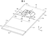
- FIG. 2 is a perspective view of the display device 10 according to the present embodiment.
- the display device 10 forms a stereoscopic image visually recognized by the user in a space without a screen.
- FIG. 2 shows a state in which the display device 10 displays a stereoscopic image I, more specifically, a button-shaped stereoscopic image I on which the characters “ON” are displayed.
- the display device 10 includes a light guide plate 11 and a lighting device 12.
- the light guide plate 11 guides the light incident from the lighting device 12, reflects it by the optical path changing portions 13a, 13b and 13c (described later) formed at predetermined positions, and emits the light from the exit surface 11a (described later).
- the light guide plate 11 has a rectangular parallelepiped shape and is formed of a resin material having transparency and a relatively high refractive index.
- the material forming the light guide plate 11 may be, for example, a polycarbonate resin, a polymethyl methacrylate resin, glass, or the like.
- the light guide plate 11 has an exit surface 11a (light emission surface) that emits light, a back surface 11b on the opposite side of the emission surface 11a, and end faces 11c, end faces 11d, end faces 11e, and end faces 11f that are four end faces.
- the end surface 11c is an incident surface on which the light projected from the lighting device 12 is incident on the light guide plate 11.
- the end surface 11d is a surface opposite to the end surface 11c.
- the end surface 11e is a surface opposite to the end surface 11f.
- a plurality of optical path changing portions including an optical path changing portion 13a, an optical path changing portion 13b, and an optical path changing portion 13c are formed on the back surface 11b of the light guide plate 11.
- the plurality of optical path changing portions are formed substantially continuously along a predetermined direction. In other words, the plurality of optical path changing portions are formed along predetermined lines in a plane parallel to the exit surface 11a.
- a predetermined direction in which the optical path changing portion is formed substantially continuously is referred to as a Z-axis direction.
- the direction perpendicular to the exit surface 11a is referred to as the X-axis direction
- the direction perpendicular to both the X-axis direction and the Z-axis direction is referred to as the Y-axis direction.
- the optical path changing unit substantially converges the light incident on each position of the optical path changing unit to a fixed point corresponding to each optical path changing unit.
- the optical path changing section 13a, the optical path changing section 13b, and the optical path changing section 13c are particularly shown as a part of the optical path changing section, and each of the optical path changing section 13a, the optical path changing section 13b, and the optical path changing section 13c is shown.
- a state in which a plurality of lights emitted from each of the optical path changing unit 13a, the optical path changing unit 13b, and the optical path changing unit 13c converge is shown.
- the optical path changing unit 13a corresponds to the fixed point PA of the stereoscopic image I. That is, the light from each position of the optical path changing portion 13a converges on the fixed point PA. Therefore, the wave surface of the light from the optical path changing unit 13a becomes the wave surface of the light emitted from the fixed point PA.
- the optical path changing units 13b and 13c correspond to the fixed points PB and PC on the stereoscopic image I, respectively. That is, the light from each position of the optical path changing portions 13b and 13c converges on the fixed point PB and the PC, respectively. In this way, the light from each position of the arbitrary optical path changing unit 13 substantially converges to the fixed point corresponding to each optical path changing unit 13.
- an arbitrary optical path changing unit 13 can provide a wave surface of light such that light is emitted from a corresponding fixed point.
- the fixed points corresponding to each optical path changing unit 13 are different from each other, and the user is placed on the space (more specifically, on the space on the exit surface 11a side from the light guide plate 11) by a collection of a plurality of fixed points corresponding to the optical path changing units 13.
- the stereoscopic image I recognized by is imaged.
- the optical path changing section 13a, the optical path changing section 13b, and the optical path changing section 13c are formed along the line La, the line Lb, and the line Lc, respectively.
- the line La, the line Lb, and the line Lc are straight lines substantially parallel to the Z-axis direction.
- the arbitrary optical path changing portion 13 is formed substantially continuously along a straight line parallel to the Z-axis direction.
- the light guide plate 11 forms a stereoscopic image I in a space other than the light guide plate 11 by the light emitted from the exit surface 11a.
- the display device 10 can display an image in space.
- the light guide plate 11 may display a flat image inside the light guide plate 11 by the light emitted from the light emitting surface 11a. In this case, the display device 10 can display a flat image.
- the lighting device 12 causes light to enter the light guide plate 11.
- the lighting device 12 is provided at the end portion of the back surface 11b along the end surface 11c.
- the lighting device 12 causes parallel light collimated in a direction perpendicular to the back surface 11b on a plane parallel to the end surface 11c of the light guide plate 11 to enter the light guide plate 11 from the back surface 11b.
- a specific configuration example of the lighting device 12 will be described below.
- FIG. 1 is a front view of the lighting device 12 according to the present embodiment.
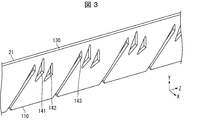
- FIG. 3 is a perspective view of the light guide member unit 21 included in the lighting device 12.
- the lighting device 12 includes a light guide member unit 21 and a plurality of light sources 22.
- the light guide member unit 21 includes a plurality of light guide members 100. More specifically, in the light guide member unit 21, a plurality of light guide members 100 are continuously formed on a resin material (translucent material) having a rectangular parallelepiped shape and having transparency and a relatively high refractive index. Has a configuration that
- the light source 22 is a light source that causes light to enter the light guide member unit 21.
- the light source 22 is, for example, an LED (Light Emitting diode) light source.
- the light guide member 100 includes an incident surface 110, a plurality of partially totally reflecting surfaces 121, 122 and 123, and an exit surface 130.
- the incident surface 110 is a surface on which the light from the light source 22 is incident from a predetermined incident position P.
- the predetermined incident position P will be described later.
- the exit surface 130 is a surface that emits the light that is totally reflected by each of the partially totally reflected surfaces 121 to 123. As shown in FIG. 3, in the present embodiment, the exit surface 130 is a rectangular plane.
- the partially totally reflecting surfaces 121 to 123 totally reflect the light incident from the incident surface 110. More specifically, the partial total reflection surfaces 121 to 123 have a shape that totally reflects the light so that the light incident from the predetermined incident position is emitted from the emission surface 130 in the direction perpendicular to the emission surface 130. It has become. Therefore, the light incident from the incident surface 110 is totally reflected by any of the partial total reflection surfaces 121 to 123, and is emitted from the emission surface 130 in the direction perpendicular to the emission surface 130. Therefore, it is possible to emit light having the same emission direction according to the shape of the emission surface 130. Further, the number of the total internal reflection surfaces included in the light guide member 100 is not limited to 3, and may be 2 or 4 or more.
- the partial total reflection surfaces 121 to 123 when the direction parallel to the incident surface 110, the exit surface 130, and the partial total reflection surfaces 121 to 123 is the thickness direction, the partial total reflection surfaces 121 to 123 have a cross-sectional shape perpendicular to the thickness direction.
- Each is a parabola.
- the light source 22 is arranged at the focal point of the parabola.
- the predetermined incident position P on the incident surface 110 where the light from the light source 22 is incident is the position where the light from the light source 22 arranged at the focal point of the parabolic shape of the partial total reflection surfaces 121 to 123 is incident. be. Therefore, the light guide member 100 can emit parallel light from the exit surface 130 by reflecting the light incident on the light guide member 100 from the light source 22 on the partially total reflection surfaces 121 to 123.
- each of the partial total reflection surfaces 121 to 123 may be one of the hyperbolas. Also in this case, by arranging the light source 22 at the focal position of the hyperbola, parallel light can be emitted from the emission surface 130.
- the light guide member 100 is provided with hollow portions 141 and 142 and a notch portion 143.
- the hollow portions 141 and 142 are cavities provided inside the resin material constituting the light guide member 100.
- the notch portion 143 is a notch portion formed by notching the resin material constituting the light guide member 100 from the side of the incident surface 110.
- the hollow portions 141 and 142 are formed by using a mold having a shape in which the hollow portions 141 and 142 are formed, for example, when the light guide member unit 21 is formed by injection molding.
- the hollow portions 141 and 142 are formed by, for example, manufacturing the light guide member unit 21 in which the hollow portions 141 and 142 are not formed, and then hollowing out the light guide member unit 21.
- the notch portion 143 may be formed by using a mold having a shape in which the notch portion 143 is formed, and the light guide member unit having a shape in which the notch portion 143 does not exist. It may be formed by cutting out the light guide member unit 21 after manufacturing the 21.
- the partial total reflection surfaces 121 to 123 the partial total reflection surfaces 121 and 122 (inner partial total reflection surfaces) provided inside the light guide member 100 are formed by the surfaces of the hollow portions 141 and 142, respectively. Will be done. Further, the partial total reflection surface 123 whose one end is in contact with the incident surface 110 is formed by the surface of the notch portion 143. Therefore, the light guide member 100 can be easily manufactured as compared with a method such as forming the partially total internal reflection surfaces 121 to 123 by embedding another material in the resin material, for example.
- the surface of the hollow portion 141 other than the partial total reflection surface 121 is a region on the exit surface 130 side of the surface including (i) the end portion of the partial total reflection surface 122 on the exit surface 130 side and (ii) the light source 22. Only exists in. Therefore, the light to be incident on the partial total reflection surface 122 is not blocked by the surface of the hollow portion 141 other than the partial total reflection surface 121.
- the surface 1411 which is one of the surfaces of the hollow portion 141, passes through an end portion of the partial total reflection surface 122 that is perpendicular to the exit surface 130 and is separated from the exit surface 130.
- the surface 1411 exists in a region on the light source 22 side of the region through which the light reflected by the partially totally reflected surface 122 passes.
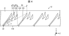
- FIG. 4 is a diagram showing a region of the emitted light from the emitting surface 130 and an angular range of the light traveling direction in the light guide member 100.
- the light directed from the light source 22 toward both ends of the partial total reflection surfaces 121 to 123 and the light reflected at both ends are indicated by broken line arrows.
- the regions of the light emitted from the exit surface 130 are the region R1 of the light totally reflected by the partially totally reflected surface 121, the region R2 of the light totally reflected by the partially totally reflected surface 122, and the region R2 of the light. It is divided into the region R3 of the light totally reflected by the partially totally reflecting surface 123.
- the regions R1 to R3 of the light reflected by the respective partial total reflection surfaces 121 to 123 are adjacent to each other. Therefore, uniform light emission can be realized without creating a dark region between the regions R1 to R3 of the light reflected by the respective partial total reflection surfaces 121 to 123.
- the total reflection surface in order to emit light from a wide area of the emission surface 130, and the light is incident accordingly. It becomes necessary to increase the distance between the surface 110 and the exit surface 130. In this case, the size of the light guide member 100 is increased.
- the light guide member 100 a plurality of partially totally reflecting surfaces 121, 122 and 123 are provided. Therefore, in order to emit light from a wide area of the exit surface 130, the number of partially total reflection surfaces may be increased, so that it is not necessary to increase the distance between the incident surface 110 and the exit surface 130. Therefore, the light guide member 100 that emits light from a wide area of the exit surface 130 can be miniaturized.
- the exit surface 130, and the partial total reflection surfaces 121 to 123 is the thickness direction
- reflection is performed by the respective partial total reflection surfaces 121 to 123 in the cross-sectional shape perpendicular to the thickness direction.
- the light regions are adjacent to each other on the exit surface 130.
- the angle range of the light incident from the incident surface 110 in the traveling direction is divided into a plurality of partial angle ranges ⁇ , ⁇ , and ⁇ adjacent to each other.
- one partial total reflection surface 121 to 123 is provided. More specifically, the partial angle range ⁇ is provided with the partial total reflection surface 121, the partial angle range ⁇ is provided with the partial total reflection surface 122, and the partial angle range ⁇ is provided with the partial total reflection surface 123. There is. Therefore, on the exit surface 130 of the light guide member 100, the regions of light reflected by the respective partial total reflection surfaces 121 to 123 are adjacent to each other.
- the exit surfaces 130 included in each light guide member 100 are arranged so as to be adjacent to each other on the same surface.
- the exit surface 130 of each light guide member 100 is a portion of a common surface that is different from each other. Therefore, the light guide member unit 21 can emit parallel light over a wide range without increasing the distance between the incident surface 110 and the exit surface 130 of each light guide member 100. Therefore, the size of the light guide member unit 21 capable of emitting parallel light in a certain range can be reduced.
- the lighting device 12 includes a light guide member unit 21 and a plurality of light sources 22. Therefore, as the light guide member 100 included in the light guide member unit 21 is miniaturized, the lighting device 12 can also be miniaturized. Further, as described above, the display device 10 includes a lighting device 12 and a light guide plate 11. Therefore, as the lighting device 12 becomes smaller, the display device 10 can also be made smaller.
- the partial total reflection surfaces 121 to 123 are preferably arranged in a direction parallel to the exit surface 130. By arranging the partially total reflection surfaces 121 to 123 in this way, the light guide member 100 can be miniaturized in the direction in which light is emitted from the emission surface 130.
- the ends of the partially total reflection surfaces 121 to 123 have a predetermined first curvature in a cross section perpendicular to the thickness direction of the light guide member 100.
- the first curvature is preferably about 0.2 to 0.5 ° / m. Since the ends of the partially totally reflecting surfaces 121 to 123 have such a curvature, the mold for manufacturing the light guide member 100 can have a long life.
- the optical axis of the light source 22 faces the direction of the partial total reflection surface 123 of the partial total reflection surfaces 121 to 123, which is the farthest from the light source 22.
- the intensity of the light emitted from the light source is the highest in the optical axis and decreases as the distance from the optical axis increases.
- the partial total reflection surface 123 farthest from the light source 22 is formed to be larger in size than the partial total reflection surfaces 121 and 122. Therefore, when the direction of the optical axis having the highest intensity faces the partially total reflection surface 123, the overall brightness of the light emitted from the exit surface 130 can be made uniform.
- FIG. 5 is a diagram showing a state in which the display device 10 is applied to the tail lamp of the vehicle C.
- the display device 10 can be applied to the tail lamp 1A of the vehicle C, for example, as shown by reference numeral 5001 in FIG.
- the display device 10 includes a light guide plate 11A and a lighting device 12, as shown by reference numeral 5002 in FIG.
- the light guide plate 11A is different from the light guide plate 11 in that it has a curved shape that matches the shape of the vehicle C.
- the stereoscopic image I is displayed by changing the optical path of the light incident from the lighting device 12 by the optical path changing unit 13 formed in the light guide plate 11A.
- the display device 10 may be applied to a vehicle lamp or a vehicle display device other than the tail lamp.
- the display device 10 can be applied to an input unit such as an aerial switch.
- the aerial switch may include a display device 10 and a sensor that detects the presence or absence of an object at the position of the image displayed by the display device 10.
- the aerial switch receives a user's input operation on an image displayed in space by the display device 10 by a sensor.
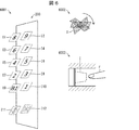
- FIG. 6 is a diagram showing a state in which the display device 10 is applied to the input unit of the elevator.
- the display device 10 can be applied to, for example, the input unit 200 of an elevator.
- the input unit 200 displays the stereoscopic images I1 to I12 by the display device 10.
- the stereoscopic images I1 to I12 are displays that accept input from a user who specifies the destination (floor number) of the elevator (stereoscopic images I1 to I10) or displays that accept instructions for opening and closing the elevator doors (stereoscopic images I11 and I12). It is an imaged stereoscopic image.
- the input unit 200 When the input unit 200 receives a user's input for any of the stereoscopic images I, the input unit 200 changes the imaging state of the stereoscopic image I (for example, changes the color of the stereoscopic image I) and responds to the input. Is output to the control unit of the elevator.
- the stereoscopic image I may be displayed by the input unit 200 only when a person approaches the input unit 200. Further, the input unit 200 may be arranged inside the wall of the elevator.
- the display device 10 may display a stereoscopic image I that prompts the user to perform a rotation operation, for example, as shown by reference numeral 6002 in FIG.
- the input unit 200 may accept the user's input only when the rotation operation is received for the stereoscopic image I by, for example, the motion sensor.
- the rotation operation is an operation that is not normally performed unless the user intends to do so, it is possible to prevent the input unit 200 from accepting an input not intended by the user.
- the stereoscopic image I may be displayed in a recess provided in the inner wall of the elevator. As a result, since the input to the stereoscopic image I is performed only when the user's finger or the like is inserted into the recess, it is possible to prevent the input unit 200 from accepting the input not intended by the user.
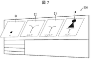
- FIG. 7 is a diagram showing a state in which the display device 10 is applied to the input unit of the warm water toilet seat washer.
- the display device 10 can be applied to, for example, the input unit 300 (operation panel unit) of the warm water toilet seat washer.
- the input unit 300 displays the stereoscopic images I1 to I4 by the display device 10.
- the stereoscopic images I1 to I4 are stereoscopic images in which a display for receiving an instruction to drive / stop the cleaning function of the warm water toilet seat washer is formed.
- the input unit 300 When the input unit 300 receives a user's input for any of the stereoscopic images I, the input unit 300 changes the imaging state of the stereoscopic image I (for example, changes the color of the stereoscopic image I) and responds to the input.
- the instruction to be used is output to the control unit of the hot water toilet seat washer.
- Many users do not like direct contact with the operation panel of the warm water toilet seat washer for hygiene reasons.
- the user can operate without directly touching (physically touching) the input unit 300. Therefore, the user can operate without worrying about hygiene.
- the input device of the present invention can also be applied to other devices for which direct contact is not preferable in terms of hygiene.
- the input device of the present invention is suitable for application to a reference number ticketing machine installed in a hospital, an operation unit of a moving door touched by an unspecified person, and the like. Further, when there are a plurality of options such as surgery and internal medicine in the reference number ticketing machine installed in the hospital, the stereoscopic image I corresponding to each option can be displayed, which is preferable. Further, the input device of the present invention is suitable for application to a cash register or a meal ticket vending machine installed in a restaurant.
- the display device 10 includes, for example, an ATM (Automated teller machine) input unit, an input unit for a credit card reader, an input unit for unlocking a safe, and a door for unlocking with a personal identification number. It can be applied to the input section and the like.
- an ATM Automated teller machine
- input is performed by physically touching the input unit with a finger. In such a case, a fingerprint or a temperature history remains in the input unit. Therefore, there is a risk that the password will be known to others.
- the display device 10 is used as an input unit, fingerprints and temperature histories do not remain, so that it is possible to prevent the personal identification number from being known to others.
- the input device 1 can be applied to a ticket vending machine installed at a station or the like.
- the display device 10 is a vanity lighting switch, a faucet operation switch, a range hood operation switch, a dishwasher operation switch, a refrigerator operation switch, a microwave oven operation switch, and an IH (Induction Heating) cooking heater operation. It can also be applied to switches, operation switches for electrolyzed water generators, operation switches for interphones, lighting switches in corridors, or operation switches for compact stereo systems.
- the switch is smooth and easy to clean, (ii) the stereoscopic image can be displayed only when necessary, and the design is improved.
- Iii) Contact with the switch There are advantages that it is hygienic because there is no need to do it, and (iv) it is hard to break because there are no moving parts.
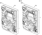
- FIG. 8 is a perspective view showing an example of a gaming machine to which the display device 10 is applied.
- the display device 10 is not shown.
- the display device 10 can also be applied to an input device of a gaming machine. Similar to the above-mentioned aerial switch, the input device in this case may also include a display device 10 and a sensor for detecting the presence or absence of an object at the position of the image displayed by the display device 10.
- the stereoscopic image I is imaged by the display device 10 as at least one of the plurality of switches operated by the user. You may let me.
- a display device displays a stereoscopic image I as a switch that is formed so as to be superimposed on a screen on which an effect image for the user is displayed on the gaming machine M2 and is an operation target of the user.
- the image may be formed by 10.
- the display device 10 may display the stereoscopic image I only when it is necessary for the effect.
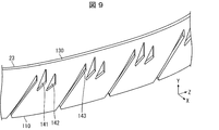
- FIG. 9 is a perspective view showing a light guide member unit 23 according to a modified example of the light guide member unit 21.
- the light guide member unit 23 is different from the light guide member unit 21 in that the exit surface 130 is not rectangular.
- the exit surface 130 has a shape in which the long sides of the rectangle are changed into arcs that are convex in the same direction. Similar to the light guide member unit 21, such a light guide member unit 23 can also emit parallel light from the emission surface 130.
- FIG. 10 is a perspective view showing the configuration of the light guide member unit 24 according to the modified example of the light guide member unit 21. As shown in FIG. 10, the light guide member unit 24 differs from the light guide member unit 21 in that the exit surface 130 of each light guide member 100 is a curved surface.
- the light guide member 100 included in the light guide member unit 24 when the direction parallel to the incident surface 110, the exit surface 130, and the partially totally reflecting surfaces 121 to 123 is the thickness direction, the cross-sectional shape perpendicular to the thickness direction Each of the partially totally reflecting surfaces 121 to 123 has a shape that totally reflects the light so that the light incident from the incident position is emitted from the emitting surface 130 in the direction perpendicular to the emitting surface 130. Therefore, the light guide member 100 included in the light guide member unit 24 can emit light from the curved exit surface 130 in a direction perpendicular to the emission surface 130. In this case, when the emitted light is bent in a direction parallel to the thickness direction and guided, the guided light can be converted into parallel light.
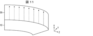
- FIG. 11 is a perspective view showing an application example of the lighting device 12 including the light guide member unit 24.
- the light emitted from the lighting device 12 is incident on the light guide plate 30 and is bent in the light guide plate 30 in a direction parallel to the thickness direction of the light guide member unit 24.
- the light guided through the light guide plate 30 becomes parallel light as shown by the broken line in FIG.
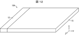
- FIG. 12 is a perspective view of the display device 10A.
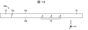
- FIG. 13 is a cross-sectional view showing the configuration of the display device 10A.
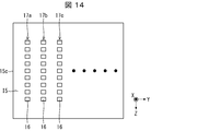
- FIG. 14 is a plan view showing the configuration of the display device 10A.
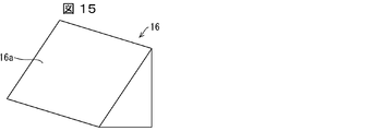
- FIG. 15 is a perspective view showing the configuration of the optical path changing unit 16 included in the display device 10A.
- the display device 10A includes a lighting device 12 and a light guide plate 15 (first light guide plate).
- the light guide plate 15 is a member that guides the light (incident light) incident from the lighting device 12.
- the light guide plate 15 is made of a transparent resin material having a relatively high refractive index.
- a polycarbonate resin, a polymethyl methacrylate resin, or the like can be used as the material for forming the light guide plate 15, for example, a polycarbonate resin, a polymethyl methacrylate resin, or the like can be used. In this modification, the light guide plate 15 is formed of a polymethylmethacrylate resin.
- the light guide plate 15 includes an emitting surface 15a (light emitting surface), a back surface 15b, and an incident surface 15c.
- the exit surface 15a is a surface that guides the inside of the light guide plate 15 and emits light whose optical path has been changed by the optical path changing unit 16 described later.
- the exit surface 15a constitutes the front surface of the light guide plate 15.
- the back surface 15b is a surface parallel to the exit surface 15a, and is a surface on which the optical path changing portion 16 described later is arranged.
- the incident surface 15c is a surface on which the light emitted from the illuminating device 12 is incident inside the light guide plate 15.
- the light emitted from the lighting device 12 and incident on the light guide plate 15 from the incident surface 15c is totally reflected by the exit surface 15a or the back surface 15b, and is guided through the light guide plate 15.
- the optical path changing portion 16 is formed on the back surface 15b inside the light guide plate 15 to change the optical path of the light guided in the light guide plate 15 and emit it from the exit surface 15a. It is a member. A plurality of optical path changing portions 16 are provided on the back surface 15b of the light guide plate 15.
- the optical path changing portion 16 is provided along the direction parallel to the incident surface 15c.
- the optical path changing portion 16 has a triangular pyramid shape and includes a reflecting surface 16a that reflects (totally reflected) the incident light.
- the optical path changing portion 16 may be, for example, a recess formed in the back surface 15b of the light guide plate 15. Further, the optical path changing portion 16 is not limited to the triangular pyramid shape.
- a plurality of optical path changing unit groups 17a, 17b, 17c ... Consisting of a plurality of optical path changing units 16 are formed on the back surface 15b of the light guide plate 15.
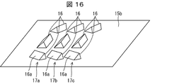
- FIG. 16 is a perspective view showing the arrangement of the optical path changing portions 16.
- the reflecting surfaces 16a of the plurality of optical path changing portions 16 are arranged on the back surface 15b of the light guide plate 15 so that the angles with respect to the incident direction of the light are different from each other. Has been done.
- each of the optical path changing unit groups 17a, 17b, 17c Changes the optical path of the incident light and emits the incident light from the emitting surface 15a in various directions.
- a method of forming a stereoscopic image I by the display device 10A will be described with reference to FIG.
- a case will be described in which a stereoscopic image I as a surface image is formed on the stereoscopic image forming surface P which is a plane perpendicular to the exit surface 15a of the light guide plate 15 by the light whose optical path is changed by the optical path changing unit 16. ..
- FIG. 17 is a perspective view showing a method of forming a stereoscopic image I by the display device 10A.
- a ring mark with diagonal lines is formed as a stereoscopic image I on the stereoscopic image forming surface P.
- the light whose optical path is changed by each optical path changing unit 16 of the optical path changing unit group 17a intersects the stereoscopic image imaging surface P at the line La1 and the line La2.
- the line image LI which is a part of the stereoscopic image I, is formed on the stereoscopic image forming surface P.
- the line image LI is a line image parallel to the YZ plane.
- the line image LI of the line La1 and the line La2 is formed by the light from a large number of optical path changing units 16 belonging to the optical path changing unit group 17a.
- the light for forming the images of the line La1 and the line La2 may be provided by at least two optical path changing units 16 in the optical path changing unit group 17a.
- each optical path changing unit 16 of the optical path changing unit group 17b intersects the stereoscopic image imaging surface P at the line Lb1, the line Lb2, and the line Lb3.
- the line image LI which is a part of the stereoscopic image I, is formed on the stereoscopic image forming surface P.
- each optical path changing unit 16 of the optical path changing unit group 17c intersects the stereoscopic image imaging surface P at the line Lc1 and the line Lc2.
- the line image LI which is a part of the stereoscopic image I, is formed on the stereoscopic image forming surface P.
- the positions of the line images LI formed by the optical path changing unit groups 17a, 17b, 17c ... In the X-axis direction are different from each other.
- the distance between the optical path changing unit groups 17a, 17b, 17c ... the distance in the X-axis direction of the line image LI imaged by the optical path changing unit groups 17a, 17b, 17c ... It can be made smaller.
- a stereoscopic image I which is a surface image, is formed on the stereoscopic image forming surface P.
- the stereoscopic image forming surface P may be a plane perpendicular to the X axis, a plane perpendicular to the Y axis, or a plane perpendicular to the Z axis. Further, the stereoscopic image forming surface P may be a plane that is not perpendicular to the X-axis, the Y-axis, or the Z-axis. Further, the stereoscopic image forming surface P may be a curved surface instead of a flat surface. That is, the display device 10A can form a stereoscopic image I on an arbitrary surface (plane and curved surface) in space by the optical path changing unit 16. In addition, a three-dimensional image can be formed by combining a plurality of surface images.
- the display device 10 may separately image images for a plurality of viewpoints.
- the display device 10 may include a display pattern for the right eye that forms an image for the right eye and a display pattern for the left eye that forms an image for the left eye.
- the display device 10 can form an image having a stereoscopic effect.
- the display device 10 may separately form images for three or more viewpoints.
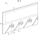
- FIG. 18 is a diagram showing a configuration of a display device 10B as a modification of the display device 10.
- the light guide member 100 of the lighting device 12 and the light guide plate 11 are separate bodies.
- the light emitted from the exit surface 130 of the light guide member 100 is incident from the end surface 11c of the light guide plate 11, the optical path is changed by the optical path changing unit 13, and the light is emitted from the emission surface 11a of the light guide plate 11.
- the light guide plate 11 is formed integrally with the light guide member unit 21. Specifically, in the display device 10B, the exit surface 130 of the light guide member 100 and the end surface 11c of the light guide plate 11 are integrally formed. According to such a display device 10B, the number of parts can be reduced as compared with the display device 10.
- FIG. 19 is a diagram showing incident positions P1 and P2, which are modified examples of incident positions P in which light from the light source 22 is incident on the light guide member 100.
- the incident positions P1 and P2 have a predetermined second curvature on a plan surface perpendicular to the thickness direction of the light guide member 100.
- the incident position P1 has a concave shape having a predetermined curvature with respect to the light source 22. Therefore, the light incident from the incident position P1 is guided in a wider angle range as compared with the case where the light is incident from the incident position P having a planar shape.
- the incident position P2 has a convex shape having a predetermined curvature with respect to the light source 22. Therefore, the light incident from the incident position P2 is guided in a narrow angle range as compared with the case where the light is incident from the incident position P having a planar shape.
- the angle range of the light guided in the light guide member 100 can be adjusted.
- the second curvature may be appropriately determined according to a desired angle range of the light guided through the light guide member 100.
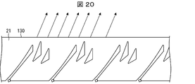
- FIG. 20 is a diagram showing a modified example of the light guide member unit 21. As shown by the arrows in FIG. 20, the light guide member unit 21 may emit light that is not parallel to the emission surface 130. Such a light guide member unit 21 is also included in the scope of the present invention.
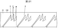
- FIG. 21 is a diagram showing a modified example of the light guide member unit 21.
- the light guide member units 21 may emit light that is not completely parallel to each other and has a slight spread.
- the slight spread is, for example, a spread of 5 ° or less, preferably 3 ° or less.
- the light guide member includes an incident surface on which light from a light source is incident from a predetermined incident position, a plurality of partial total reflecting surfaces that totally reflect the light incident from the incident surface, and the portion.
- the shape is such that the light is totally reflected, and among the partial total reflecting surfaces, the inner partial total reflecting surface provided inside the light guide member is made of the translucent material constituting the light guide member.
- the surface of the hollow portion other than the partial total reflection surface is formed by the surface of the hollow portion provided inside, and (i) the partial total reflection surface of the partial total reflection surface adjacent to the lower side of the separation from the light source. It exists only in the region on the exit surface side of the surface including the end portion on the exit surface side and (ii) the light source, and is reflected by each of the partial total reflection surfaces on the exit surface. The regions of light are adjacent to each other.
- the light incident from the incident surface is totally reflected by the partial total reflection surface including the inner partial total reflection surface formed by the surface of the hollow portion, and is emitted from the exit surface. Therefore, it is possible to emit light having the same emission direction according to the shape of the emission surface.
- each of the partial total reflection surfaces is a plurality of regions between the incident surface and the exit surface. It is possible to disperse and arrange them in places. Therefore, the distance between the entrance surface and the exit surface can be reduced, and the light guide member can be miniaturized.
- the total reflection surface is divided into a plurality of parts in this way, since the regions of light reflected by each partial total reflection surface are adjacent to each other on the emission surface, the light is reflected by each partial total reflection surface. It is possible to realize uniform light emission without creating a dark region between the light regions.
- the emission surface, and the partial total reflection surface is the thickness direction
- the thickness is the thickness.
- each of the partial total reflection surfaces is a parabolic line.
- the thickness is the thickness.
- each of the partial total reflection surfaces is one of the bicurves.
- the thickness is the thickness.
- each of the partial total reflection surfaces reflects the light so that the light incident from the incident position is emitted from the emission surface in the direction perpendicular to the emission surface. It has become.
- a light guide member capable of emitting light from a curved emission surface in a direction perpendicular to the emission surface.
- the guided light can be converted into parallel light.
- the cross-sectional shape perpendicular to the thickness direction is divided into a plurality of partial angle ranges adjacent to each other, and one partial total reflection surface is provided within each of the partial angle ranges. ing.
- the plurality of partially total reflection surfaces are arranged in a direction parallel to the emission surface.
- the light guide member can be miniaturized in the direction in which light is emitted.
- the ends of the plurality of partial total reflection surfaces are formed so as to have a predetermined first curvature in a cross section perpendicular to the thickness direction of the light guide member. ing.
- the life of the mold for manufacturing the light guide member can be extended.
- the incident position is formed so as to have a predetermined second curvature in a cross section perpendicular to the thickness direction of the light guide member.
- the spread of the light incident on the light guide member can be adjusted by the second curvature.
- the light guide member unit includes a plurality of the light guide members described above, and is arranged such that the emission surfaces of the light guide members are on the same surface and adjacent to each other.
- the light guide member unit capable of emitting parallel light over a wide range without increasing the distance between the incident surface and the exit surface of each light guide member. Therefore, the light guide member unit capable of emitting parallel light in a certain range can be miniaturized.
- the lighting device includes the above-mentioned light guide member unit and a plurality of light sources.
- the light source is arranged so that the optical axis of the light faces the direction of the farthest from the light source among the plurality of partial total reflection surfaces.
- the optical axis with the highest light intensity faces the direction of the farthest, that is, the widest area of the total internal reflection surface. Therefore, the overall brightness of the light emitted from the exit surface can be made uniform.
- the display device guides the above-mentioned lighting device and the light incident from the lighting device, reflects it by an optical path changing portion formed at a predetermined position, and emits the light from the light emitting surface. It is provided with a light guide plate to be used.
- the light guide plate forms an image in a space other than the light guide plate by the light emitted from the light emitting surface.
- a stereoscopic image can be displayed by the display device.
- the light guide plate displays a flat image inside the light guide plate by the light emitted from the light emitting surface.
- a flat image can be displayed by the display device.
- the light guide plate is integrally formed with the light guide member unit.
- the number of parts of the display device can be reduced.
Landscapes
- Physics & Mathematics (AREA)
- Engineering & Computer Science (AREA)
- General Physics & Mathematics (AREA)
- General Engineering & Computer Science (AREA)
- Theoretical Computer Science (AREA)
- Optics & Photonics (AREA)
- Planar Illumination Modules (AREA)
- Light Guides In General And Applications Therefor (AREA)
- Illuminated Signs And Luminous Advertising (AREA)
Abstract
広範囲に平行光を出射可能な導光部材を小型化する。導光部材(100)は、光を全反射させる部分全反射面(121~123)と、部分全反射面で全反射された光を出射する出射面(130)とを備え、部分全反射面は、入射面(110)の入射位置から入射した光が、出射面に垂直な方向に出射されるように光を全反射する形状になっているとともに、出射面において、部分全反射面で反射された光の領域が互いに隣接している。
Description
本発明は入射光を導光し、平行光として出射させる導光部材、ならびに当該導光部材を備える導光部材ユニット、照明装置および表示装置に関する。
特許文献1には、所定の光軸に沿って光を照射する車両用灯具ユニットが開示されている。当該車両用灯具ユニットは、光源から出射された光を導光体内へ入射させる入射面と、前面に形成された出射面及び第一反射面と、後面に形成された第二反射面とを有する。車両用灯具ユニットは、入射面から導光体内へ入射した光を、第一反射面で後方へ内部反射させた後に、第二反射面で前方への平行光としつつ出射面へ内部反射させる。
しかしながら、特許文献1に開示されている車両用灯具ユニットにおいて、広範囲に平行光を出射させようとすると、第二反射面を大型化する必要がある。当該車両用灯具ユニットにおいて第二反射面を大型化すると、導光体全体のサイズ、特に照射する光の光軸方向におけるサイズが大型化するという問題がある。
本発明の一態様は、広範囲に平行光を出射可能な導光部材などを小型化することを目的とする。
上記の課題を解決するために、本発明の一態様に係る導光部材は、光源からの光が所定の入射位置から入射する入射面と、前記入射面から入射した前記光を全反射させる複数の部分全反射面と、前記部分全反射面でそれぞれ全反射された前記光を出射する出射面とを備える導光部材であって、前記部分全反射面は、前記入射位置から入射した前記光が、前記出射面から出射されるように前記光を全反射する形状になっているとともに、前記部分全反射面のうち、当該導光部材の内部に設けられる内側部分全反射面は、当該導光部材を構成する透光材料の内部に設けられた中空部の面によって形成され、前記中空部の、前記部分全反射面以外の面は、(i)当該部分全反射面の前記光源から離隔下側に隣接する部分全反射面の、前記出射面側の端部、および(ii)前記光源、を含む面よりも、前記出射面側の領域にのみ存在し、前記出射面において、それぞれの前記部分全反射面で反射された光の領域が互いに隣接している。
本発明の一態様によれば、広範囲に平行光を出射可能な導光部材などを小型化することができる。
以下、本発明の一側面に係る実施の形態(以下、「本実施形態」とも表記する)を、図面に基づいて説明する。
§1 適用例
図2は、本実施形態に係る表示装置10の斜視図である。表示装置10は、ユーザにより視認される立体画像をスクリーンのない空間に結像する。図2では、表示装置10が立体画像I、より具体的には、「ON」の文字が表示されたボタン形状の立体画像Iを表示している様子を示している。図2に示すように、表示装置10は、導光板11と、照明装置12とを備えている。
図2は、本実施形態に係る表示装置10の斜視図である。表示装置10は、ユーザにより視認される立体画像をスクリーンのない空間に結像する。図2では、表示装置10が立体画像I、より具体的には、「ON」の文字が表示されたボタン形状の立体画像Iを表示している様子を示している。図2に示すように、表示装置10は、導光板11と、照明装置12とを備えている。
導光板11は、照明装置12から入射した光を導光し、所定の位置に形成された光路変更部13a、13bおよび13c(後述)によって反射させて出射面11a(後述)から出射させる。導光板11は、直方体形状をしており、透明性および比較的高い屈折率を有する樹脂材料で成形されている。導光板11を形成する材料は、例えばポリカーボネイト樹脂、ポリメチルメタクリレート樹脂、ガラスなどであってよい。導光板11は、光を出射する出射面11a(光出射面)と、出射面11aとは反対側の背面11bと、四方の端面である、端面11c、端面11d、端面11eおよび端面11fとを備えている。端面11cは、照明装置12から投射された光が導光板11に入射する入射面である。端面11dは、端面11cとは反対側の面である。端面11eは、端面11fとは反対側の面である。
導光板11の背面11bには、光路変更部13a、光路変更部13b、および光路変更部13cを含む複数の光路変更部が形成されている。複数の光路変更部は、所定の方向に沿って実質的に連続して形成されている。換言すれば、複数の光路変更部は、出射面11aに平行な面内でそれぞれ予め定められた線に沿って形成されている。
以下の説明では、光路変更部が実質的に連続して形成されている所定の方向をZ軸方向と称する。また、出射面11aに垂直な方向をX軸方向と称し、X軸方向およびZ軸方向の両方に垂直な方向をY軸方向と称する。
光路変更部のZ軸方向の各位置には、照明装置12から投射され導光板11によって導光されている光が入射する。光路変更部は、当該光路変更部の各位置に入射した光を、各光路変更部にそれぞれ対応する定点に実質的に収束させる。図2には、光路変更部の一部として、光路変更部13a、光路変更部13b、および光路変更部13cが特に示され、光路変更部13a、光路変更部13b、および光路変更部13cのそれぞれにおいて、光路変更部13a、光路変更部13b、および光路変更部13cのそれぞれから出射された複数の光が収束する様子が示されている。
具体的には、光路変更部13aは、立体画像Iの定点PAに対応する。すなわち、光路変更部13aの各位置からの光は、定点PAに収束する。したがって、光路変更部13aからの光の波面は、定点PAから発するような光の波面となる。同様に、光路変更部13bおよび13cは、それぞれ立体画像I上の定点PBおよびPCに対応する。すなわち、光路変更部13bおよび13cの各位置からの光は、それぞれ定点PBおよびPCに収束する。このように、任意の光路変更部13の各位置からの光は、各光路変更部13に対応する定点に実質的に収束する。これにより、任意の光路変更部13によって、対応する定点から光が発するような光の波面を提供できる。各光路変更部13が対応する定点は互いに異なり、光路変更部13にそれぞれ対応する複数の定点の集まりによって、空間上(より詳細には、導光板11から出射面11a側の空間上)にユーザにより認識される立体画像Iが結像される。
図2に示すように、光路変更部13a、光路変更部13b、および光路変更部13cは、線La、線Lbおよび線Lcに沿ってそれぞれ形成されている。ここで、線La、線Lbおよび線Lcは、Z軸方向に略平行な直線である。任意の光路変更部13は、Z軸方向に平行な直線に沿って実質的に連続的に形成される。
以上の構成により、導光板11は、出射面11aから出射させる光により、導光板11以外の空間に立体画像Iを結像させる。これにより、表示装置10は空間に画像を表示することができる。ただし、導光板11は、出射面11aから出射させる光により、導光板11の内部に平面画像を表示してもよい。この場合、表示装置10は平面画像を表示することができる。
照明装置12は、導光板11へ光を入射させる。図2に示す例では、照明装置12は、背面11bの、端面11cに沿う端部に設けられる。照明装置12は、導光板11の端面11cに平行な平面において背面11bに垂直な方向にコリメートされた平行光を、背面11bから導光板11へ入射させる。照明装置12の具体的な構成例について、以下に説明する。
§2 構成例
図1は、本実施形態に係る照明装置12の正面図である。図3は、照明装置12が備える導光部材ユニット21の斜視図である。図1に示すように、照明装置12は、導光部材ユニット21と、複数の光源22とを備える。
図1は、本実施形態に係る照明装置12の正面図である。図3は、照明装置12が備える導光部材ユニット21の斜視図である。図1に示すように、照明装置12は、導光部材ユニット21と、複数の光源22とを備える。
導光部材ユニット21は、導光部材100を複数備える。より詳細には、導光部材ユニット21は、直方体形状を有し、かつ透明性および比較的高い屈折率を有する樹脂材料(透光材料)に、複数の導光部材100が連続的に形成されている構成を有する。
光源22は、導光部材ユニット21に光を入射させる光源である。光源22は、例えばLED(Light Emitting diode)光源である。
導光部材100は、入射面110と、複数の部分全反射面121、122および123と、出射面130とを備える。入射面110は、光源22からの光が所定の入射位置Pから入射する面である。所定の入射位置Pについては後述する。出射面130は、部分全反射面121~123のそれぞれで全反射された前記光を出射する面である。図3に示すように、本実施形態では出射面130は矩形の平面である。
部分全反射面121~123は、入射面110から入射した光を全反射させる。より詳細には、部分全反射面121~123は、所定の入射位置から入射した光が出射面130から当該出射面130に垂直な方向に出射されるように、当該光を全反射する形状になっている。このため、入射面110から入射した光は、部分全反射面121~123のいずれかで全反射されて、出射面130から当該出射面130に垂直な方向に出射されることになる。よって、出射面130の形状に応じて出射方向が揃った光を出射させることが可能となる。また、導光部材100が備える部分全反射面の数は3に限定されず、2であっても、また4以上であってもよい。
本実施形態では、入射面110、出射面130、および、部分全反射面121~123に平行な方向を厚み方向とした場合、厚み方向に垂直な断面形状において、部分全反射面121~123のそれぞれは放物線となっている。また、光源22は、放物線の焦点に配置されている。換言すれば、入射面110において光源22からの光が入射する所定の入射位置Pは、部分全反射面121~123が有する放物線形状の焦点に配された光源22からの光が入射する位置である。このため、導光部材100は、光源22から導光部材100へ入射した光を部分全反射面121~123で反射することで、出射面130から平行光を出射することができる。
また、上記断面形状において、部分全反射面121~123のそれぞれは、双曲線の一方であってもよい。この場合にも、双曲線の焦点位置に光源22を配置することによって、出射面130から平行光を出射することができる。
図1および図3に示すように、導光部材100には中空部141および142、ならびに切欠き部143が設けられている。中空部141および142は、導光部材100を構成する樹脂材料の内部に設けられた空洞である。また、切欠き部143は、導光部材100を構成する樹脂材料を、入射面110の側から切り欠くことで形成された切欠き部である。中空部141および142は、例えば導光部材ユニット21を射出成型により形成する場合に、中空部141および142が形成される形状の金型を用いることで形成される。または、中空部141および142は、例えば中空部141および142が形成されていない状態の導光部材ユニット21を製造した後に、当該導光部材ユニット21をくり抜くことで形成される。
切欠き部143は、中空部141および142と同様に、切欠き部143が形成される形状の金型を用いることで形成されてもよく、切欠き部143が存在しない形状の導光部材ユニット21を製造した後に当該導光部材ユニット21を切り欠くことで形成されてもよい。
本実施形態では、部分全反射面121~123のうち、導光部材100の内部に設けられる部分全反射面121および122(内側部分全反射面)はそれぞれ、中空部141および142の面によって形成される。また、一端が入射面110と接する部分全反射面123は、切欠き部143の面によって形成される。このため、例えば樹脂材料に別の材料を埋め込むことで部分全反射面121~123を形成するなどの方法と比較して、導光部材100を容易に製造することができる。
中空部141の、部分全反射面121以外の面は、(i)部分全反射面122の出射面130側の端部、および(ii)光源22を含む面よりも、出射面130側の領域にのみ存在する。このため、部分全反射面122に入射すべき光が、中空部141の、部分全反射面121以外の面によって遮られることがない。
一例として、中空部141が有する面の1つである面1411は、出射面130に垂直であり、かつ、部分全反射面122の出射面130から離隔した側の端部を通過する。また、別の例として、面1411は、部分全反射面122により反射された光が通過する領域よりも、光源22側の領域に存在する。
図4は、出射面130からの出射光の領域、および、導光部材100における光の進行方向の角度範囲を示す図である。図4においては、光源22から部分全反射面121~123のそれぞれの両端へ向かう光、および当該両端で反射される光が破線矢印で示されている。図4に示すように、出射面130から出射される光の領域は、部分全反射面121により全反射された光の領域R1、部分全反射面122により全反射された光の領域R2、および部分全反射面123により全反射された光の領域R3に区分される。ここで、出射面130において、それぞれの部分全反射面121~123で反射された光の領域R1~R3は互いに隣接している。このため、それぞれの部分全反射面121~123で反射された光の領域R1~R3の間に暗い領域が生じることなく、均一な光出射を実現することができる。
仮に単一の全反射面で出射方向が揃った光を出射させようとする場合、出射面130の広い領域から光を出射させるためには、全反射面を大きくする必要があり、これに従って入射面110と出射面130との距離を大きくする必要が生じる。この場合、導光部材100の大型化を招くことになる。
これに対し、導光部材100においては、複数の部分全反射面121、122および123が設けられている。このため、出射面130の広い領域から光を出射させるためには部分全反射面の数を増加させればよいため、入射面110と出射面130との距離を大きくする必要はない。このため、出射面130の広い領域から光を出射させる導光部材100を小型化することができる。
なお、入射面110、出射面130、および、部分全反射面121~123に平行な方向を厚み方向とした場合、厚み方向に垂直な断面形状において、それぞれの部分全反射面121~123で反射された光の領域が出射面130において互いに隣接している。
また、図4に示す例では、導光部材100において、入射面110から入射した光の進行方向の角度範囲は、互いに隣接する複数の部分角度範囲α、βおよびγに分割されている。それぞれの部分角度範囲α、β、γ内に、部分全反射面121~123が1つ設けられている。より詳細には、部分角度範囲αには部分全反射面121が設けられ、部分角度範囲βには部分全反射面122が設けられ、部分角度範囲γには部分全反射面123が設けられている。このため、導光部材100の出射面130において、それぞれの部分全反射面121~123で反射された光の領域が互いに隣接する。
また、導光部材ユニット21においては、各導光部材100が備える出射面130が同一面上で互いに隣接するように配置されている。具体的には、各導光部材100の出射面130は、共通の面の互いに異なる部分である。このため、導光部材ユニット21は、各導光部材100における入射面110と出射面130との距離を大きくすることなく、広い範囲に平行光を出射できる。このため、一定の範囲に平行光を出射可能な導光部材ユニット21のサイズを小型化することができる。
また、上述したとおり、照明装置12は、導光部材ユニット21と、複数の光源22を備える。このため、導光部材ユニット21が備える導光部材100の小型化に伴い、照明装置12も小型化できる。また、上述したとおり、表示装置10は、照明装置12と、導光板11とを備える。このため、照明装置12の小型化に伴い、表示装置10も小型化できる。
また、部分全反射面121~123は、出射面130に平行な方向に配列されることが好ましい。部分全反射面121~123をこのように配列することで、出射面130から光が出射される方向において、導光部材100を小型化できる。
また、部分全反射面121~123の端部は、導光部材100の厚み方向に垂直な断面において、所定の第1曲率を有する。第1曲率は0.2~0.5°/m程度であることが好ましい。部分全反射面121~123の端部がこのような曲率を有することで、導光部材100を製造するための金型を長寿命とすることができる。
また、光源22は、光軸が、部分全反射面121~123のうち光源22から最も遠い部分全反射面123の方向を向くことが好ましい。ここで、光源から出射される光の強度は、光軸において最も高く、光軸から離隔するにしたがって低下するものとする。
図4に示すように、部分全反射面121~123のうちで、光源22から最も遠い部分全反射面123は、部分全反射面121および122と比較してサイズが大きく形成されている。このため、最も強度が高い光軸の方向が部分全反射面123を向くことで、出射面130から出射される光の全体的な明るさを均一にすることができる。
§3 動作例
図5は、表示装置10を車両Cのテールランプに適用した様子を示す図である。表示装置10は、例えば図5の符号5001に示すように、車両Cのテールランプ1Aに適用することができる。この場合、表示装置10は、図5の符号5002に示すように、導光板11Aと照明装置12とを備える。導光板11Aは、車両Cの形状に合わせて湾曲した形状を有する点で導光板11と相違する。照明装置12から入射した光が、導光板11A内に形成された光路変更部13により光路変更されることで、立体画像Iが表示される。また、表示装置10は、テールランプ以外の車両用灯具または車両用表示装置に適用されてもよい。
図5は、表示装置10を車両Cのテールランプに適用した様子を示す図である。表示装置10は、例えば図5の符号5001に示すように、車両Cのテールランプ1Aに適用することができる。この場合、表示装置10は、図5の符号5002に示すように、導光板11Aと照明装置12とを備える。導光板11Aは、車両Cの形状に合わせて湾曲した形状を有する点で導光板11と相違する。照明装置12から入射した光が、導光板11A内に形成された光路変更部13により光路変更されることで、立体画像Iが表示される。また、表示装置10は、テールランプ以外の車両用灯具または車両用表示装置に適用されてもよい。
また、表示装置10は、例えば空中スイッチなどの入力部に適用することができる。この場合、空中スイッチは、表示装置10と、表示装置10が表示する画像の位置における物体の有無を検出するセンサとを備えていればよい。当該空中スイッチは、表示装置10が空間に表示する画像に対するユーザの入力操作をセンサにより受け付ける。
図6は、表示装置10をエレベータの入力部に適用した様子を示す図である。図6の符号6001に示すように、表示装置10は、例えばエレベータの入力部200に適用することができる。具体的には、入力部200は、表示装置10により立体画像I1~I12を表示する。立体画像I1~I12は、エレベータの行先(階数)を指定するユーザの入力を受け付ける表示(立体画像I1~I10)、または、エレベータの扉の開閉の指示を受け付ける表示(立体画像I11・I12)が結像された立体画像である。入力部200は、いずれかの立体画像Iに対するユーザの入力を受け付けた場合、当該立体画像Iの結像状態を変化させる(例えば、立体画像Iの色を変化させるなど)とともに、当該入力に対応する指示をエレベータの制御部に対して出力する。入力部200による立体画像Iの表示は、入力部200に人が近づいたときにのみ行うようにしてもよい。また、入力部200は、エレベータの壁の内部に配置されてもよい。
エレベータの入力部200では、例えば、エレベータ内に人が多い場合では、ユーザの体の一部が立体画像Iの結像位置に位置してしまい、入力部200がユーザの意図していない入力を受け付けてしまう虞がある。そこで、入力部200において、表示装置10は、例えば図6の符号6002に示すような、ユーザに回転操作を促すような立体画像Iを表示してもよい。この場合において、入力部200は、例えばモーションセンサによって立体画像Iに対して回転操作を受け付けた場合にのみユーザの入力を受け付けるようにしてもよい。回転操作は、ユーザが意図しないかぎり通常は行われない操作であるので、入力部200がユーザの意図していない入力を受け付けてしまうことを防止することができる。また、図6の符号6003に示すように、立体画像Iがエレベータの内壁に設けられた凹部に表示される構成としてもよい。これにより、ユーザの指などが上記凹部に挿入されたときにのみ立体画像Iに対する入力が行われるので、入力部200がユーザの意図していない入力を受け付けてしまうことを防止することができる。
図7は、表示装置10を温水便座洗浄機の入力部に適用した様子を示す図である。図7に示すように、表示装置10は、例えば温水便座洗浄機の入力部300(操作パネル部)に適用することができる。具体的には、入力部300は、表示装置10により立体画像I1~I4を表示する。立体画像I1~I4は、温水便座洗浄機の洗浄機能の駆動・停止の指示を受け付ける表示が結像された立体画像である。入力部300は、いずれかの立体画像Iに対するユーザの入力を受け付けた場合、当該立体画像Iの結像状態を変化させる(例えば、立体画像Iの色を変化させるなど)とともに、当該入力に対応する指示を温水便座洗浄機の制御部に対して出力する。温水便座洗浄機の操作パネルは、衛生上、直接触ることを好まないユーザが多い。これに対して、入力部300では、ユーザは、入力部300に直接触る(物理的に触る)ことなく操作をすることができる。したがって、ユーザは、衛生面を気にすることなく操作をすることができる。なお、本発明の入力装置は、衛生面的に直接触ることが好ましくない他の装置にも適用することができる。例えば、本発明の入力装置は、病院に設置される整理番号発券機や、不特定の人が触る移動ドアの操作部などに適用するのに好適である。また、病院に設置される整理番号発券機において外科や内科などの複数の選択肢がある場合に、それぞれの選択肢に対応する立体画像Iを表示することができるため好適である。また、本発明の入力装置は、飲食店に設置されるレジまたは食券販売機に適用するのに好適である。
そのほかにも表示装置10は、例えば、ATM(Automated teller machine)の入力部、クレジットカードの読み取り器における入力部、金庫における施錠を解除するための入力部、暗証番号による開錠が行われるドアの入力部などに適用することができる。ここで、従来の暗証番号入力装置では、物理的に入力部に指を接触させることにより入力を行っている。このような場合には、入力部に指紋や温度履歴が残ってしまう。そのため、他人に暗証番号を知られてしまうという虞があった。これに対して、表示装置10を入力部として用いた場合、指紋や温度履歴が残ることが無いため、暗証番号を他人に知られてしまうことを防ぐことができる。その他の例として、入力装置1を駅などに設置される券売機などに適用することができる。
さらに、表示装置10は、洗面化粧台の照明スイッチ、蛇口の操作スイッチ、レンジフードの操作スイッチ、食器洗い機の操作スイッチ、冷蔵庫の操作スイッチ、電子レンジの操作スイッチ、IH(Induction Heating)クッキングヒータの操作スイッチ、電解水生成装置の操作スイッチ、インターホンの操作スイッチ、廊下の照明スイッチ、またはコンパクトステレオシステムの操作スイッチなどにも適用可能である。これらのスイッチに表示装置10を適用することで、(i)スイッチに凹凸がなくなるため掃除しやすい、(ii)必要時のみ立体画像を表示できるためデザイン性が向上する、(iii)スイッチに接触する必要がなくなるため衛生的である、(iv)可動部がなくなるため壊れにくくなる、といった利点が生じる。
図8は、表示装置10が適用された遊技機の一例を示す斜視図である。図8では、表示装置10の図示は省略している。図8に示すように、表示装置10は、遊技機の入力装置に適用することもできる。この場合における入力装置も、上述した空中スイッチと同様、表示装置10と、表示装置10が表示する画像の位置における物体の有無を検出するセンサとを備えていればよい。
図8の符号8001に示すように、遊技機M1に対してユーザが操作する操作盤において、ユーザが操作する複数のスイッチのうちの少なくとも1つのスイッチとして、立体画像Iを表示装置10によって結像させてもよい。また、図8の符号8002に示すように、遊技機M2においてユーザに対する演出画像が表示される画面に重ねるように結像され、かつ、ユーザの操作対象となるスイッチとしての立体画像Iを表示装置10によって結像させてもよい。この場合、表示装置10は、演出上必要な場合にのみ立体画像Iを表示させてもよい。
§4 変形例
以上、本発明の実施の形態を詳細に説明してきたが、前述までの説明はあらゆる点において本発明の例示に過ぎない。本発明の範囲を逸脱することなく種々の改良や変形を行うことができることは言うまでもない。例えば、以下のような変更が可能である。なお、以下では、上記実施形態と同様の構成要素に関しては同様の符号を用い、上記実施形態と同様の点については、適宜説明を省略した。以下の変形例は適宜組み合わせ可能である。
以上、本発明の実施の形態を詳細に説明してきたが、前述までの説明はあらゆる点において本発明の例示に過ぎない。本発明の範囲を逸脱することなく種々の改良や変形を行うことができることは言うまでもない。例えば、以下のような変更が可能である。なお、以下では、上記実施形態と同様の構成要素に関しては同様の符号を用い、上記実施形態と同様の点については、適宜説明を省略した。以下の変形例は適宜組み合わせ可能である。
<4.1>
図9は、導光部材ユニット21の変形例に係る導光部材ユニット23を示す斜視図である。図9に示すように、導光部材ユニット23は、出射面130が矩形ではない点で導光部材ユニット21とは異なる。図9に示す例では、出射面130は、矩形の長辺を互いに同じ方向に凸な円弧に変更した形状を有する。このような導光部材ユニット23も、導光部材ユニット21と同様、出射面130から平行光を出射することができる。
図9は、導光部材ユニット21の変形例に係る導光部材ユニット23を示す斜視図である。図9に示すように、導光部材ユニット23は、出射面130が矩形ではない点で導光部材ユニット21とは異なる。図9に示す例では、出射面130は、矩形の長辺を互いに同じ方向に凸な円弧に変更した形状を有する。このような導光部材ユニット23も、導光部材ユニット21と同様、出射面130から平行光を出射することができる。
<4.2>
図10は、導光部材ユニット21の変形例に係る導光部材ユニット24の構成を示す斜視図である。図10に示すように、導光部材ユニット24は、それぞれの導光部材100における出射面130が曲面である点で導光部材ユニット21と相違する。
図10は、導光部材ユニット21の変形例に係る導光部材ユニット24の構成を示す斜視図である。図10に示すように、導光部材ユニット24は、それぞれの導光部材100における出射面130が曲面である点で導光部材ユニット21と相違する。
導光部材ユニット24が備える導光部材100において、入射面110、出射面130、および、部分全反射面121~123に平行な方向を厚み方向とした場合、厚み方向に垂直な断面形状において、部分全反射面121~123のそれぞれは、入射位置から入射した光が出射面130から当該出射面130に垂直な方向に出射されるように光を全反射する形状になっている。このため、導光部材ユニット24が備える導光部材100は、曲面である出射面130から、当該出射面130に垂直な方向に光を出射することが可能となる。この場合、出射された光が、前記厚み方向に平行な方向に曲げられて導光される場合に、その導光された光を平行光とすることが可能となる。
図11は、導光部材ユニット24を備える照明装置12の適用例を示す斜視図である。図11に示す例では、照明装置12から出射された光が導光板30に入射し、導光板30内で導光部材ユニット24の厚み方向に平行な方向に曲げられている。このとき、導光板30内を導光される光は、図11に破線で示すように平行光となる。
<4.3>
表示装置10の変形例としての表示装置10Aについて、図12~図17を参照しながら説明する。
表示装置10の変形例としての表示装置10Aについて、図12~図17を参照しながら説明する。
図12は、表示装置10Aの斜視図である。図13は、表示装置10Aの構成を示す断面図である。図14は、表示装置10Aの構成を示す平面図である。図15は、表示装置10Aが備える光路変更部16の構成を示す斜視図である。
図12および図13に示すように、表示装置10Aは、照明装置12と、導光板15(第1導光板)とを備えている。
導光板15は、照明装置12から入射された光(入射光)を導光する部材である。導光板15は、透明で屈折率が比較的高い樹脂材料で成形される。導光板15を形成する材料としては、例えばポリカーボネイト樹脂、ポリメチルメタクリレート樹脂などを使用することができる。本変形例では、導光板15は、ポリメチルメタクリレート樹脂によって成形されている。導光板15は、図13に示すように、出射面15a(光出射面)と、背面15bと、入射面15cとを備えている。
出射面15aは、導光板15の内部を導光され、後述する光路変更部16により光路変更された光を出射する面である。出射面15aは、導光板15の前面を構成している。背面15bは、出射面15aと互いに平行な面であり、後述する光路変更部16が配置される面である。入射面15cは、照明装置12から出射された光が導光板15の内部に入射される面である。
照明装置12から出射され入射面15cから導光板15に入射した光は、出射面15aまたは背面15bで全反射され、導光板15内を導光される。
図13に示すように、光路変更部16は、導光板15の内部において背面15bに形成されており、導光板15内を導光された光を光路変更して出射面15aから出射させるための部材である。光路変更部16は、導光板15の背面15bに複数設けられている。
光路変更部16は、図14に示すように、入射面15cに平行な方向に沿って設けられている。図15に示すように、光路変更部16は、三角錐形状となっており、入射した光を反射(全反射)する反射面16aを備えている。光路変更部16は、例えば、導光板15の背面15bに形成された凹部であってもよい。また、光路変更部16は、三角錐形状に限られるものではない。導光板15の背面15bには、図14に示すように、複数の光路変更部16からなる複数の光路変更部群17a、17b、17c…が形成されている。
図16は、光路変更部16の配列を示す斜視図である。図16に示すように、各光路変更部群17a、17b、17c…では、複数の光路変更部16の反射面16aが光の入射方向に対する角度が互いに異なるように導光板15の背面15bに配置されている。これにより、各光路変更部群17a、17b、17c…は、入射光を光路変更して、出射面15aから様々な方向へ出射させる。
次に、表示装置10Aによる立体画像Iの結像方法について、図17を参照しながら説明する。ここでは、導光板15の出射面15aに垂直な面である立体画像結像面Pに、光路変更部16により光路変更された光によって面画像としての立体画像Iを結像する場合について説明する。
図17は、表示装置10Aによる立体画像Iの結像方法を示す斜視図である。ここでは、立体画像結像面Pに立体画像Iとして斜め線入りリングマークを結像することについて説明する。
表示装置10Aでは、図17に示すように、例えば、光路変更部群17aの各光路変更部16によって光路変更された光は、立体画像結像面Pに線La1および線La2で交差する。これにより、立体画像結像面Pに立体画像Iの一部である線画像LIを結像させる。線画像LIは、YZ平面に平行な線画像である。このように、光路変更部群17aに属する多数の光路変更部16からの光によって、線La1および線La2の線画像LIが結像される。なお、線La1および線La2の像を結像する光は、光路変更部群17aにおける少なくとも2つの光路変更部16によって提供されていればよい。
同様に、光路変更部群17bの各光路変更部16によって光路変更された光は、立体画像結像面Pに線Lb1、線Lb2および線Lb3で交差する。これにより、立体画像結像面Pに立体画像Iの一部である線画像LIを結像させる。
また、光路変更部群17cの各光路変更部16によって光路変更された光は、立体画像結像面Pに線Lc1および線Lc2で交差する。これにより、立体画像結像面Pに立体画像Iの一部である線画像LIを結像させる。
各光路変更部群17a、17b、17c…によって結像される線画像LIのX軸方向の位置は互いに異なっている。表示装置10Aでは、光路変更部群17a、17b、17c…間の距離を小さくすることによって、各光路変更部群17a、17b、17c…によって結像される線画像LIのX軸方向の距離を小さくすることができる。その結果、表示装置10Aでは、光路変更部群17a、17b、17c…の各光路変更部16によって光路変更された光によって結像された複数の線画像LIを集積することにより、実質的に、面画像である立体画像Iを立体画像結像面Pに結像する。
立体画像結像面Pは、X軸に垂直な平面であってもよく、Y軸に垂直な平面であってもよく、またZ軸に垂直な平面であってもよい。また、立体画像結像面Pは、X軸、Y軸、またはZ軸に垂直でない平面であってもよい。さらに、立体画像結像面Pは、平面ではなく曲面であってもよい。すなわち、表示装置10Aは、光路変更部16によって空間上の任意の面(平面および曲面)上に立体画像Iを結像させることができる。また、面画像を複数組み合わせることにより、3次元の画像を結像することができる。
<4.4>
入力装置1において、表示装置10は、複数の視点用の画像を別個に結像させてもよい。例えば表示装置10は、右目用画像を結像させる右目用表示パターンと、左目用画像を結像させる左眼用表示パターンとを含んでいてよい。この場合、表示装置10は、立体感のある画像を結像させることができる。また、表示装置10は、3以上の視点用の画像を別個に結像させてよい。
入力装置1において、表示装置10は、複数の視点用の画像を別個に結像させてもよい。例えば表示装置10は、右目用画像を結像させる右目用表示パターンと、左目用画像を結像させる左眼用表示パターンとを含んでいてよい。この場合、表示装置10は、立体感のある画像を結像させることができる。また、表示装置10は、3以上の視点用の画像を別個に結像させてよい。
<4.5>
図18は、表示装置10の変形例としての表示装置10Bの構成を示す図である。表示装置10においては、照明装置12の導光部材100と、導光板11とが別体であった。導光部材100の出射面130から出射された光が、導光板11の端面11cから入射し、光路変更部13により光路変更されて導光板11の出射面11aから出射される。
図18は、表示装置10の変形例としての表示装置10Bの構成を示す図である。表示装置10においては、照明装置12の導光部材100と、導光板11とが別体であった。導光部材100の出射面130から出射された光が、導光板11の端面11cから入射し、光路変更部13により光路変更されて導光板11の出射面11aから出射される。
これに対し、表示装置10Bにおいては、導光板11は、導光部材ユニット21と一体に形成される。具体的には、表示装置10Bにおいては、導光部材100の出射面130と導光板11の端面11cとが一体に形成される。このような表示装置10Bによれば、表示装置10と比較して部品点数を削減できる。
<4.6>
図19は、光源22からの光が導光部材100に入射する入射位置Pの変形例である、入射位置P1およびP2を示す図である。入射位置P1およびP2は、導光部材100の厚み方向に垂直な案面において、所定の第2曲率を有する。
図19は、光源22からの光が導光部材100に入射する入射位置Pの変形例である、入射位置P1およびP2を示す図である。入射位置P1およびP2は、導光部材100の厚み方向に垂直な案面において、所定の第2曲率を有する。
図19の符号1901に示す例では、入射位置P1は、光源22に対して所定の曲率の凹形状を有する。このため、入射位置P1から入射した光は、平面形状である入射位置Pから入射した場合と比較して広い角度範囲を導光される。一方、図19の符号1902に示す例では、入射位置P2は、光源22に対して所定の曲率の凸形状を有する。このため、入射位置P2から入射した光は、平面形状である入射位置Pから入射した場合と比較して狭い角度範囲を導光される。
このように、入射位置Pの代わりに入射位置P1またはP2から光を入射させることで、導光部材100内を導光される光の角度範囲を調整できる。第2曲率は、導光部材100内を導光される光の、所望の角度範囲に応じて適宜決定されればよい。
<4.7>
図20は、導光部材ユニット21の変形例を示す図である。図20において矢印で示すように、導光部材ユニット21は、出射面130に平行でない光を出射してもよい。このような導光部材ユニット21も、本願発明の範囲に含まれる。
図20は、導光部材ユニット21の変形例を示す図である。図20において矢印で示すように、導光部材ユニット21は、出射面130に平行でない光を出射してもよい。このような導光部材ユニット21も、本願発明の範囲に含まれる。
<4.8>
図21は、導光部材ユニット21の変形例を示す図である。図21において矢印で示すように、導光部材ユニット21は、互いに完全に平行ではなく、わずかな広がりを有する光を出射してもよい。わずかな広がりは、例えば5°以下、望ましくは3°以下の広がりである。導光部材ユニット21が出射する光にこのような広がりを持たせることで、部分全反射面121~123の端部で発生する暗線を目立たなくすることができる。
図21は、導光部材ユニット21の変形例を示す図である。図21において矢印で示すように、導光部材ユニット21は、互いに完全に平行ではなく、わずかな広がりを有する光を出射してもよい。わずかな広がりは、例えば5°以下、望ましくは3°以下の広がりである。導光部材ユニット21が出射する光にこのような広がりを持たせることで、部分全反射面121~123の端部で発生する暗線を目立たなくすることができる。
本発明の一態様に係る導光部材は、光源からの光が所定の入射位置から入射する入射面と、前記入射面から入射した前記光を全反射させる複数の部分全反射面と、前記部分全反射面でそれぞれ全反射された前記光を出射する出射面とを備える導光部材であって、前記部分全反射面は、前記入射位置から入射した前記光が、前記出射面から出射されるように前記光を全反射する形状になっているとともに、前記部分全反射面のうち、当該導光部材の内部に設けられる内側部分全反射面は、当該導光部材を構成する透光材料の内部に設けられた中空部の面によって形成され、前記中空部の、前記部分全反射面以外の面は、(i)当該部分全反射面の前記光源から離隔下側に隣接する部分全反射面の、前記出射面側の端部、および(ii)前記光源、を含む面よりも、前記出射面側の領域にのみ存在し、前記出射面において、それぞれの前記部分全反射面で反射された光の領域が互いに隣接している。
上記の構成によれば、入射面から入射した光は、中空部の面によって形成された内側部分全反射面を含む部分全反射面で全反射されて、出射面から出射されることになる。よって、出射面の形状に応じて出射方向が揃った光を出射させることが可能となる。
また、例えば1つの全反射面で上記のような光を出射させようとすると、出射面の広い領域から光を出射させるためには、全反射面を大きくする必要があり、これに従って入射面と出射面との距離を大きくする必要が生じる。この場合、導光部材の大型化を招くことになる。これに対して、上記の構成によれば、入射した光を全反射させる部分全反射面が複数設けられているので、それぞれの部分全反射面を入射面と出射面との間の領域の複数箇所に分散して配置することが可能となる。よって、入射面と出射面との距離を小さくすることが可能となり、導光部材の小型化を図ることができる。
さらに、このように全反射面を複数に分割したとしても、出射面において、それぞれの部分全反射面で反射された光の領域が互いに隣接しているので、それぞれの部分全反射面で反射された光の領域の間に暗い領域が生じることなく均一な光出射を実現することができる。
なお、前記入射面、前記出射面、および、前記部分全反射面に平行な方向を厚み方向とした場合、前記厚み方向に垂直な断面形状において、それぞれの前記部分全反射面で反射された光の領域が前記出射面において互いに隣接している。
また、本発明の一態様に係る導光部材において、前記出射面は平面であり、前記入射面、前記出射面、および、前記部分全反射面に平行な方向を厚み方向とした場合、前記厚み方向に垂直な断面形状において、前記部分全反射面のそれぞれは放物線となっている。
上記の構成によれば、前記放物線の焦点位置に前記光源を配置することによって、出射面から平行光を出射することが可能な導光部材を提供することができる。
また、本発明の一態様に係る導光部材において、前記出射面は平面であり、前記入射面、前記出射面、および、前記部分全反射面に平行な方向を厚み方向とした場合、前記厚み方向に垂直な断面形状において、前記部分全反射面のそれぞれは双曲線の一方となっている。
上記の構成によれば、前記双曲線の焦点位置に前記光源を配置することによって、出射面から平行光を出射することが可能な導光部材を提供することができる。
また、本発明の一態様に係る導光部材において、前記出射面は曲面であり、前記入射面、前記出射面、および、前記部分全反射面に平行な方向を厚み方向とした場合、前記厚み方向に垂直な断面形状において、前記部分全反射面のそれぞれは、前記入射位置から入射した前記光が前記出射面から前記出射面に垂直な方向に出射されるように前記光を全反射する形状になっている。
上記の構成によれば、曲面である出射面から、当該出射面に垂直な方向に光を出射することが可能な導光部材を提供することができる。この場合、出射された光が、前記厚み方向に平行な方向に曲げられて導光される場合に、その導光された光を平行光とすることが可能となる。
また、本発明の一態様に係る導光部材において、前記入射面、前記出射面、および、前記部分全反射面に平行な方向を厚み方向とした場合、前記厚み方向に垂直な断面形状において、前記入射面から入射した前記光の進行方向の角度範囲は、互いに隣接する複数の部分角度範囲に分割されているとともに、それぞれの前記部分角度範囲内に、前記部分全反射面が1つ設けられている。
上記の構成によれば、出射面において、それぞれの前記部分全反射面で反射された光の領域が互いに隣接している導光部材を提供することができる。
また、本発明の一態様に係る導光部材において、前記複数の部分全反射面は、前記出射面に平行な方向に配列される。
上記の構成によれば、光が出射される方向において、導光部材を小型化できる。
また、本発明の一態様に係る導光部材において、前記複数の部分全反射面の端部は、前記導光部材の厚み方向に垂直な断面において、所定の第1曲率を有するように形成されている。
上記の構成によれば、導光部材を製造するための金型を長寿命化できる。
また、本発明の一態様に係る導光部材において、前記入射位置は、前記導光部材の厚み方向に垂直な断面において、所定の第2曲率を有するように形成されている。
上記の構成によれば、導光部材へ入射した光の広がりを、第2曲率により調整できる。
また、本発明の一態様に係る導光部材ユニットは、上記の導光部材を複数備え、前記各導光部材が備える前記出射面が同一面上で互いに隣接するように配置されている。
上記の構成によれば、個々の導光部材における入射面と出射面との距離を大きくすることなく、広い範囲に平行光を出射可能な導光部材ユニットを提供することができる。このため、一定の範囲に平行光を出射可能な導光部材ユニットを小型化することができる。
また、本発明の一態様に係る照明装置は、上記の導光部材ユニットと、複数の光源とを備える。
上記の構成によれば、導光部材が小型化されることで、同様に小型化された照明装置を提供することができる。
また、本発明の一態様に係る照明装置において、前記光源は、前記光の光軸が、前記複数の部分全反射面のうち、前記光源から最も遠いものの方向を向くように配される。
上記の構成によれば、光の強度が最も高くなる光軸が、最も遠い、すなわち最も面積の広い部分全反射面の方向を向く。したがって、出射面から出射される光の全体的な明るさを均一にできる。
また、本発明の一態様に係る表示装置は、上記の照明装置と、前記照明装置から入射した光を導光し、所定の位置に形成された光路変更部によって反射させて光出射面から出射させる導光板とを備える。
上記の構成によれば、照明装置が小型化されることで、同様に小型化された表示装置を提供することができる。
また、本発明の一態様に係る表示装置において、前記導光板は、前記光出射面から出射させる光により、当該導光板以外の空間に画像を結像させる。
上記の構成によれば、表示装置により立体画像を表示することができる。
また、本発明の一態様に係る表示装置において、前記導光板は、前記光出射面から出射させる光により、前記導光板の内部に平面画像を表示する。
上記の構成によれば、表示装置により平面画像を表示することができる。
また、本発明の一態様に係る表示装置において、前記導光板は、前記導光部材ユニットと一体に形成されている。
上記の構成によれば、表示装置の部品点数を削減できる。
10、10A、10B 表示装置
11 導光板
12 照明装置
13、13a、13b、13c、16 光路変更部
21、23、24 導光部材ユニット
22 光源
100 導光部材
110 入射面
121、122、123 部分全反射面
130 出射面
141、142 中空部
11 導光板
12 照明装置
13、13a、13b、13c、16 光路変更部
21、23、24 導光部材ユニット
22 光源
100 導光部材
110 入射面
121、122、123 部分全反射面
130 出射面
141、142 中空部
Claims (15)
- 光源からの光が所定の入射位置から入射する入射面と、
前記入射面から入射した前記光を全反射させる複数の部分全反射面と、
前記部分全反射面でそれぞれ全反射された前記光を出射する出射面とを備える導光部材であって、
前記部分全反射面は、前記入射位置から入射した前記光が、前記出射面から出射されるように前記光を全反射する形状になっているとともに、
前記部分全反射面のうち、前記導光部材の内部に設けられる内側部分全反射面は、当該導光部材を構成する透光材料の内部に設けられた中空部の面によって形成され、
前記中空部の、前記部分全反射面以外の面は、
(i)当該部分全反射面の前記光源から離隔下側に隣接する部分全反射面の、前記出射面側の端部、および
(ii)前記光源、
を含む面よりも、前記出射面側の領域にのみ存在し、
前記出射面において、それぞれの前記部分全反射面で反射された光の領域が互いに隣接している導光部材。 - 前記出射面は平面であり、
前記入射面、前記出射面、および、前記部分全反射面に平行な方向を厚み方向とした場合、前記厚み方向に垂直な断面形状において、前記部分全反射面のそれぞれは放物線となっている請求項1に記載の導光部材。 - 前記出射面は平面であり、
前記入射面、前記出射面、および、前記部分全反射面に平行な方向を厚み方向とした場合、前記厚み方向に垂直な断面形状において、前記部分全反射面のそれぞれは双曲線の一方となっている請求項1に記載の導光部材。 - 前記出射面は曲面であり、
前記入射面、前記出射面、および、前記部分全反射面に平行な方向を厚み方向とした場合、前記厚み方向に垂直な断面形状において、前記部分全反射面のそれぞれは、前記入射位置から入射した前記光が前記出射面から前記出射面に垂直な方向に出射されるように前記光を全反射する形状になっている請求項1に記載の導光部材。 - 前記入射面、前記出射面、および、前記部分全反射面に平行な方向を厚み方向とした場合、前記厚み方向に垂直な断面形状において、
前記入射面から入射した前記光の進行方向の角度範囲は、互いに隣接する複数の部分角度範囲に分割されているとともに、
それぞれの前記部分角度範囲内に、前記部分全反射面が1つ設けられている請求項1~4のいずれか一項に記載の導光部材。 - 前記複数の部分全反射面は、前記出射面に平行な方向に配列される請求項1~5のいずれか1項に記載の導光部材。
- 前記複数の部分全反射面の端部は、前記導光部材の厚み方向に垂直な断面において、所定の第1曲率を有するように形成されている請求項1~6のいずれか1項に記載の導光部材。
- 前記入射位置は、前記導光部材の厚み方向に垂直な断面において、所定の第2曲率を有するように形成されている請求項1~7のいずれか1項に記載の導光部材。
- 請求項1~8のいずれか1項に記載の導光部材を複数備え、
前記各導光部材が備える前記出射面が同一面上で互いに隣接するように配置されている導光部材ユニット。 - 請求項9に記載の導光部材ユニットと、
複数の光源とを備える照明装置。 - 前記光源は、前記光の光軸が、前記複数の部分全反射面のうち、前記光源から最も遠いものの方向を向くように配される請求項10に記載の照明装置。
- 請求項10または11に記載の照明装置と、
前記照明装置から入射した光を導光し、所定の位置に形成された光路変更部によって反射させて光出射面から出射させる導光板とを備える表示装置。 - 前記導光板は、前記光出射面から出射させる光により、当該導光板以外の空間に画像を結像させる請求項12に記載の表示装置。
- 前記導光板は、前記光出射面から出射させる光により、前記導光板の内部に平面画像を表示する請求項12に記載の表示装置。
- 前記導光板は、前記導光部材ユニットと一体に形成されている請求項12~13のいずれか1項に記載の表示装置。
Applications Claiming Priority (2)
| Application Number | Priority Date | Filing Date | Title |
|---|---|---|---|
| JP2020044354A JP2021144912A (ja) | 2020-03-13 | 2020-03-13 | 導光部材、導光部材ユニット、照明装置および表示装置 |
| JP2020-044354 | 2020-03-13 |
Publications (1)
| Publication Number | Publication Date |
|---|---|
| WO2021181960A1 true WO2021181960A1 (ja) | 2021-09-16 |
Family
ID=77671347
Family Applications (1)
| Application Number | Title | Priority Date | Filing Date |
|---|---|---|---|
| PCT/JP2021/004041 Ceased WO2021181960A1 (ja) | 2020-03-13 | 2021-02-04 | 導光部材、導光部材ユニット、照明装置および表示装置 |
Country Status (2)
| Country | Link |
|---|---|
| JP (1) | JP2021144912A (ja) |
| WO (1) | WO2021181960A1 (ja) |
Citations (6)
| Publication number | Priority date | Publication date | Assignee | Title |
|---|---|---|---|---|
| JP2002251909A (ja) * | 2001-02-26 | 2002-09-06 | Nippon Sheet Glass Co Ltd | 導光板および面照明装置 |
| JP2005003734A (ja) * | 2003-06-09 | 2005-01-06 | Rohm Co Ltd | 発光表示装置 |
| JP2008078089A (ja) * | 2006-09-25 | 2008-04-03 | Stanley Electric Co Ltd | Led照明装置 |
| WO2008078543A1 (ja) * | 2006-12-26 | 2008-07-03 | Panasonic Corporation | 面状照明装置とそれを用いた液晶表示装置 |
| CN106594675A (zh) * | 2017-01-04 | 2017-04-26 | 上海小糸车灯有限公司 | Led全反射透镜和led线光源 |
| JP2018055986A (ja) * | 2016-09-29 | 2018-04-05 | オムロン株式会社 | 導光部材、導光部材ユニットおよび照明装置 |
-
2020
- 2020-03-13 JP JP2020044354A patent/JP2021144912A/ja active Pending
-
2021
- 2021-02-04 WO PCT/JP2021/004041 patent/WO2021181960A1/ja not_active Ceased
Patent Citations (6)
| Publication number | Priority date | Publication date | Assignee | Title |
|---|---|---|---|---|
| JP2002251909A (ja) * | 2001-02-26 | 2002-09-06 | Nippon Sheet Glass Co Ltd | 導光板および面照明装置 |
| JP2005003734A (ja) * | 2003-06-09 | 2005-01-06 | Rohm Co Ltd | 発光表示装置 |
| JP2008078089A (ja) * | 2006-09-25 | 2008-04-03 | Stanley Electric Co Ltd | Led照明装置 |
| WO2008078543A1 (ja) * | 2006-12-26 | 2008-07-03 | Panasonic Corporation | 面状照明装置とそれを用いた液晶表示装置 |
| JP2018055986A (ja) * | 2016-09-29 | 2018-04-05 | オムロン株式会社 | 導光部材、導光部材ユニットおよび照明装置 |
| CN106594675A (zh) * | 2017-01-04 | 2017-04-26 | 上海小糸车灯有限公司 | Led全反射透镜和led线光源 |
Also Published As
| Publication number | Publication date |
|---|---|
| JP2021144912A (ja) | 2021-09-24 |
Similar Documents
| Publication | Publication Date | Title |
|---|---|---|
| JP7434876B2 (ja) | 導光板、表示装置、入力装置および電気機器 | |
| JP7672364B2 (ja) | 入力装置 | |
| CN213445664U (zh) | 电梯的控制装置 | |
| JP7572145B2 (ja) | 入力装置 | |
| CN111062370B (zh) | 光学检测装置 | |
| CN109902664A (zh) | 红外背光单元、检测模组、背光模组、显示装置及电子设备 | |
| JP7120436B2 (ja) | 表示装置、非接触スイッチ、および電子機器 | |
| CN115685587A (zh) | 显示装置和使用该显示装置的空间输入装置 | |
| CN109919103A (zh) | 生物特征检测模组和背光模组及电子装置 | |
| TWI853527B (zh) | 非接觸按鈕 | |
| US8390470B2 (en) | Display device | |
| JP2021144912A (ja) | 導光部材、導光部材ユニット、照明装置および表示装置 | |
| JP2023173192A (ja) | 空間浮遊映像情報表示システム | |
| JP7480491B2 (ja) | 表示装置 | |
| CN114204927B (zh) | 非接触开关 | |
| CN114204928B (zh) | 非接触开关 | |
| JP2025057942A (ja) | 表示装置およびこれを備えた展示装置 | |
| JP3237054U (ja) | 非接触入力式錠前装置 | |
| CN210155693U (zh) | 光学检测装置 | |
| JP7113360B2 (ja) | 表示装置 | |
| CN210402386U (zh) | 光学检测装置 | |
| CN210402370U (zh) | 生物特征检测模组和背光模组及电子装置 | |
| JP2022122694A (ja) | 演出装置 | |
| JP7372114B2 (ja) | 自動サービス装置 | |
| CN112307845B (zh) | 光学检测装置 |
Legal Events
| Date | Code | Title | Description |
|---|---|---|---|
| 121 | Ep: the epo has been informed by wipo that ep was designated in this application |
Ref document number: 21768711 Country of ref document: EP Kind code of ref document: A1 |
|
| NENP | Non-entry into the national phase |
Ref country code: DE |
|
| 122 | Ep: pct application non-entry in european phase |
Ref document number: 21768711 Country of ref document: EP Kind code of ref document: A1 |