WO2021181858A1 - 検出結果分析装置、検出結果分析方法及び検出結果分析プログラム - Google Patents
検出結果分析装置、検出結果分析方法及び検出結果分析プログラム Download PDFInfo
- Publication number
- WO2021181858A1 WO2021181858A1 PCT/JP2021/000835 JP2021000835W WO2021181858A1 WO 2021181858 A1 WO2021181858 A1 WO 2021181858A1 JP 2021000835 W JP2021000835 W JP 2021000835W WO 2021181858 A1 WO2021181858 A1 WO 2021181858A1
- Authority
- WO
- WIPO (PCT)
- Prior art keywords
- activity
- evaluation value
- layer
- detection result
- target
- Prior art date
- Legal status (The legal status is an assumption and is not a legal conclusion. Google has not performed a legal analysis and makes no representation as to the accuracy of the status listed.)
- Ceased
Links
Images


Classifications
-
- G—PHYSICS
- G06—COMPUTING OR CALCULATING; COUNTING
- G06V—IMAGE OR VIDEO RECOGNITION OR UNDERSTANDING
- G06V10/00—Arrangements for image or video recognition or understanding
- G06V10/70—Arrangements for image or video recognition or understanding using pattern recognition or machine learning
- G06V10/764—Arrangements for image or video recognition or understanding using pattern recognition or machine learning using classification, e.g. of video objects
-
- G—PHYSICS
- G06—COMPUTING OR CALCULATING; COUNTING
- G06V—IMAGE OR VIDEO RECOGNITION OR UNDERSTANDING
- G06V20/00—Scenes; Scene-specific elements
- G06V20/70—Labelling scene content, e.g. deriving syntactic or semantic representations
-
- G—PHYSICS
- G06—COMPUTING OR CALCULATING; COUNTING
- G06T—IMAGE DATA PROCESSING OR GENERATION, IN GENERAL
- G06T7/00—Image analysis
-
- G—PHYSICS
- G06—COMPUTING OR CALCULATING; COUNTING
- G06V—IMAGE OR VIDEO RECOGNITION OR UNDERSTANDING
- G06V10/00—Arrangements for image or video recognition or understanding
- G06V10/20—Image preprocessing
- G06V10/25—Determination of region of interest [ROI] or a volume of interest [VOI]
-
- G—PHYSICS
- G06—COMPUTING OR CALCULATING; COUNTING
- G06V—IMAGE OR VIDEO RECOGNITION OR UNDERSTANDING
- G06V10/00—Arrangements for image or video recognition or understanding
- G06V10/20—Image preprocessing
- G06V10/255—Detecting or recognising potential candidate objects based on visual cues, e.g. shapes
-
- G—PHYSICS
- G06—COMPUTING OR CALCULATING; COUNTING
- G06V—IMAGE OR VIDEO RECOGNITION OR UNDERSTANDING
- G06V10/00—Arrangements for image or video recognition or understanding
- G06V10/40—Extraction of image or video features
- G06V10/44—Local feature extraction by analysis of parts of the pattern, e.g. by detecting edges, contours, loops, corners, strokes or intersections; Connectivity analysis, e.g. of connected components
- G06V10/443—Local feature extraction by analysis of parts of the pattern, e.g. by detecting edges, contours, loops, corners, strokes or intersections; Connectivity analysis, e.g. of connected components by matching or filtering
- G06V10/449—Biologically inspired filters, e.g. difference of Gaussians [DoG] or Gabor filters
- G06V10/451—Biologically inspired filters, e.g. difference of Gaussians [DoG] or Gabor filters with interaction between the filter responses, e.g. cortical complex cells
- G06V10/454—Integrating the filters into a hierarchical structure, e.g. convolutional neural networks [CNN]
-
- G—PHYSICS
- G06—COMPUTING OR CALCULATING; COUNTING
- G06V—IMAGE OR VIDEO RECOGNITION OR UNDERSTANDING
- G06V10/00—Arrangements for image or video recognition or understanding
- G06V10/70—Arrangements for image or video recognition or understanding using pattern recognition or machine learning
- G06V10/77—Processing image or video features in feature spaces; using data integration or data reduction, e.g. principal component analysis [PCA] or independent component analysis [ICA] or self-organising maps [SOM]; Blind source separation
- G06V10/80—Fusion, i.e. combining data from various sources at the sensor level, preprocessing level, feature extraction level or classification level
- G06V10/806—Fusion, i.e. combining data from various sources at the sensor level, preprocessing level, feature extraction level or classification level of extracted features
-
- G—PHYSICS
- G06—COMPUTING OR CALCULATING; COUNTING
- G06V—IMAGE OR VIDEO RECOGNITION OR UNDERSTANDING
- G06V10/00—Arrangements for image or video recognition or understanding
- G06V10/70—Arrangements for image or video recognition or understanding using pattern recognition or machine learning
- G06V10/82—Arrangements for image or video recognition or understanding using pattern recognition or machine learning using neural networks
-
- G—PHYSICS
- G06—COMPUTING OR CALCULATING; COUNTING
- G06V—IMAGE OR VIDEO RECOGNITION OR UNDERSTANDING
- G06V10/00—Arrangements for image or video recognition or understanding
- G06V10/20—Image preprocessing
- G06V10/28—Quantising the image, e.g. histogram thresholding for discrimination between background and foreground patterns
Definitions
- the present disclosure relates to a technique for analyzing the detection result by an object detection model constructed by using a neural network.
- the detection result by the object detection model that detects the target object from the image data is analyzed to identify the training data that is lacking in the object detection model (see Patent Document 1).
- the part that was the basis for the judgment by the object detection model is visualized.
- GradCAM Gradient-weighted Class Activation Mapping
- the object detection model includes a two-stage type model and a one-stage type model.
- the two-stage type model is a model that identifies a target object after narrowing down the RoI (Region of Interest) that indicates a range that is considered to be the target object.
- the one-stage type model is a model that specifies an object and the position of the object by using a set of boundary boxes of a specific size called an anchor box.
- the pooling layer after narrowing down the RoI is suitable for visualization by GradCAM.
- the layer suitable for visualization by GradCAM differs depending on the conditions such as the type of the target object and the size of the detected target object. Even in the two-stage type model, the pooling layer after narrowing down the RoI is not always the most suitable for visualization by GradCAM.
- An object of the present disclosure is to make it possible to identify a layer suitable for visualizing a part that is a basis for judgment by an object detection model.
- the detection result analyzer is An object detection model that detects an object included in image data, and the image obtained from the output result of the target layer, with each of a plurality of layers in the object detection model configured using a neural network as the target layer.
- An evaluation value calculation unit that calculates an evaluation value of the target layer from a heat map showing the activity of each pixel in the data and a detection region in which the target object is detected.
- a layer selection unit that selects at least a part of the plurality of layers based on the evaluation value calculated by the evaluation value calculation unit is provided.
- the evaluation value calculation unit calculates the evaluation value from the ratio of the inside and outside of the detection region of the activity represented by the heat map.
- the evaluation value calculation unit calculates the evaluation value from the ratio of the total value of the activity inside the detection region to the total value of the activity outside the detection region.
- the evaluation value calculation unit converts the activity into a conversion activity corresponding to the activity threshold, and when the activity is equal to or less than the activity threshold, the activity threshold is converted.
- the evaluation value is calculated after converting the activity to a conversion activity corresponding to the activity threshold one lower than the lower one.
- the layer selection unit selects a reference number of layers among the layers whose evaluation value is higher than the evaluation threshold.
- the detection result analyzer further A compositing unit is provided which synthesizes the heat map for the layer selected by the layer selecting unit to generate a compositing map.
- the synthesis unit sets each pixel of the image data as a target pixel, and sets the highest activity among the activity of the target pixel represented by the heat map for each of the selected partial layers.
- the composite map is generated by setting the activity of the target pixel in the composite map.
- the detection result analysis method is The evaluation value calculation unit is an object detection model that detects the target object included in the image data, and outputs the target layer with each of the plurality of layers in the object detection model configured using the neural network as the target layer.
- the evaluation value of the target layer is calculated from the heat map showing the activity of each pixel in the image data obtained from the result and the detection region in which the target object is detected.
- the layer selection unit selects at least a part of the plurality of layers based on the evaluation value.
- the detection result analysis program is An object detection model that detects an object included in image data, and the image obtained from the output result of the target layer, with each of a plurality of layers in the object detection model configured using a neural network as the target layer.
- Evaluation value calculation processing that calculates the evaluation value of the target layer from the heat map showing the activity of each pixel in the data and the detection area where the target object is detected.
- the computer functions as a detection result analyzer that performs a layer selection process of selecting at least a part of the layers from the plurality of layers based on the evaluation value calculated by the evaluation value calculation process.
- the evaluation value of a layer is calculated from the heat map showing the activity of each pixel in the image data and the detection area where the target object is detected, and at least a part of the layers is calculated based on the evaluation value. Select. This makes it possible to identify a layer suitable for visualization.
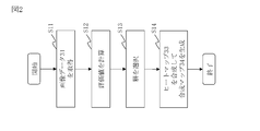
- FIG. The block diagram of the detection result analysis apparatus 10 which concerns on Embodiment 1.
- FIG. The flowchart which shows the overall operation of the detection result analysis apparatus 10 which concerns on Embodiment 1.
- FIG. The flowchart of the evaluation value calculation process which concerns on Embodiment 1.
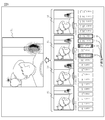
- FIG. The explanatory view of the layer selection process and the synthesis process which concerns on Embodiment 1.
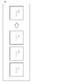
- FIG. The explanatory view of the synthesis process which concerns on Embodiment 1.
- FIG. The explanatory view of the example of the analysis based on the synthesis map 34 which concerns on Embodiment 1.
- FIG. 1 The block diagram of the detection result analysis apparatus 10 which concerns on modification 1.
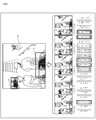
- FIG. 2 The flowchart of the evaluation value calculation process which concerns on Embodiment 2.
- the detection result analyzer 10 is a computer that identifies a layer suitable for visualizing a portion that is the basis for judgment by the object detection model.
- the detection result analyzer 10 includes hardware for a processor 11, a memory 12, a storage 13, and a communication interface 14.
- the processor 11 is connected to other hardware via a signal line and controls these other hardware.
- the processor 11 is an IC (Integrated Circuit) that performs processing. Specific examples of the processor 11 are a CPU (Central Processing Unit), a DSP (Digital Signal Processor), and a GPU (Graphics Processing Unit).
- a CPU Central Processing Unit
- DSP Digital Signal Processor
- GPU Graphics Processing Unit
- the memory 12 is a storage device that temporarily stores data. Specific examples of the memory 12 are SRAM (Static Random Access Memory) and DRAM (Dynamic Random Access Memory).
- the storage 13 is a storage device for storing data.
- the storage 13 is an HDD (Hard Disk Drive).
- the storage 13 includes SD (registered trademark, Secure Digital) memory card, CF (Compact Flash, registered trademark), NAND flash, flexible disk, optical disk, compact disk, Blu-ray (registered trademark) disk, DVD (Digital Versaille Disk), and the like. It may be a portable recording medium.
- the communication interface 14 is an interface for communicating with an external device.
- the communication interface 14 is a port of Ethernet (registered trademark), USB (Universal Serial Bus), HDMI (registered trademark, High-Definition Multimedia Interface).
- the detection result analysis device 10 includes an image acquisition unit 21, an evaluation value calculation unit 22, a layer selection unit 23, and a composition unit 24 as functional components.
- the functions of each functional component of the detection result analyzer 10 are realized by software.
- the storage 13 stores a program that realizes the functions of each functional component of the detection result analyzer 10. This program is read into the memory 12 by the processor 11 and executed by the processor 11. As a result, the functions of each functional component of the detection result analyzer 10 are realized.
- processors 11 In FIG. 1, only one processor 11 was shown. However, the number of processors 11 may be plural, and the plurality of processors 11 may execute programs that realize each function in cooperation with each other.
- the operation of the detection result analyzer 10 according to the first embodiment will be described with reference to FIGS. 2 to 6.
- the operation procedure of the detection result analysis device 10 according to the first embodiment corresponds to the detection result analysis method according to the first embodiment.
- the program that realizes the operation of the detection result analysis device 10 according to the first embodiment corresponds to the detection result analysis program according to the first embodiment.
- the object detection model is a model that detects a target object included in the image data.
- the object detection model is a model constructed by using a neural network. Since it is constructed using a neural network, the object detection model is composed of a plurality of layers.
- Step S11 in FIG. 2 Image acquisition process
- the image acquisition unit 21 acquires the image data 31 to be processed. Specifically, the image acquisition unit 21 acquires the image data 31 by reading the image data 31 set in the storage 13 by the user of the detection result analysis device 10.
- Step S12 of FIG. 2 Evaluation value calculation process
- the evaluation value calculation unit 22 calculates the evaluation value of the target layer, with each of the plurality of layers constituting the object detection model as the target layer. At this time, the evaluation value calculation unit 22 detects the target object from the heat map 33 showing the activity of each pixel in the image data 31 obtained from the output result of the target layer and the image data 31 acquired in step S11. The evaluation value is calculated from the detection area 32.
- the evaluation value calculation process according to the first embodiment will be described with reference to FIG. (Step S21 in FIG. 3: Object detection process)
- the evaluation value calculation unit 22 detects the target object by the object detection model using the image data 31 acquired in step S11 as an input.
- the type of the target object may be specified in advance or may be specified by the user.
- FIG. 4 shows a case where a bottle is specified as the type of the target object.
- Step S22 of FIG. 3 Detection area identification process
- the evaluation value calculation unit 22 identifies the detection area 32, which is the area where the target object is detected, which is specified by detecting the target object in step S21.
- Step S23 in FIG. 3 Heat map generation process
- the evaluation value calculation unit 22 generates a heat map 33 with each of the plurality of layers constituting the object detection model as a target layer. Specifically, the evaluation value calculation unit 22 generates a heat map 33 for the target layer from the output result of the target layer obtained when the target object is detected in step S21.
- the heat map 33 represents the activity of each pixel in the image data 31 acquired in step S11. Here, it is assumed that the heat map 33 shows a larger value as the pixel has a higher activity.
- the layer to be the target layer is only the layer capable of generating the heat map 33, such as the convolutional layer and the pooling layer, among the layers constituting the object detection model.
- the layer capable of generating the heat map 33 specifically refers to a layer having a plurality of channels having two or more pixels in each of the vertical and horizontal directions and capable of calculating a gradient.
- all the layers capable of generating the heat map 33 are set as the target layers.
- only a part of all the layers capable of generating the heat map 33 may be set as the target layer.
- only the layers after a certain layer may be set as the target layer.
- the layer to be processed later has a smaller number of pixels of the image data to be processed.
- the evaluation value calculation unit 22 expands the output result of the target layer to generate a heat map 33 representing the activity of each pixel of the image data 31.
- the number of pixels may be 1/4 of the image data 31 acquired in step S11.
- the evaluation value calculation unit 22 sets the heat map 33 on the assumption that one pixel represents the four pixels of the image data 31.
- the number of pixels of the image data of the output result may increase even in the layer to be processed later among the plurality of layers.
- the number of pixels of the output result may vary depending on the layer, but in any case, the number of pixels of the output result may be increased or decreased so as to match the number of pixels of the image data 31.
- Step S24 of FIG. 3 Evaluation process
- the evaluation value calculation unit 22 sets each of the plurality of layers from which the heat map 33 is generated as the target layer, and from the heat map 33 generated in step S23 for the target layer and the detection region 32 specified in step S22. Calculate the evaluation value. Specifically, the evaluation value calculation unit 22 calculates the evaluation value from the ratio of the inside and the outside of the activity detection region 32 represented by the heat map for the target layer. In the first embodiment, the evaluation value calculation unit 22 calculates the ratio of the total activity value inside the detection region 32 to the total activity value outside the detection region 32 as the evaluation value. In FIG. 4, it is assumed that the darker the hatched pixel, the higher the activity. In FIG.
- the total value of the activity inside the detection region 32 is larger than the total value of the activity outside the detection region 32, and the evaluation value is 1 or more.
- the ratio of the total activity value inside the detection area 32 to the total activity value outside the detection area 32 was calculated as the evaluation value.
- the ratio of the total activity value inside the detection region 32 to the total activity value of the entire image data 31 may be calculated as the evaluation value.
- Step S13 of FIG. 2 Layer selection process
- the layer selection unit 23 selects at least a part of the layers constituting the object detection model based on the evaluation value calculated in step S12. Specifically, the layer selection unit 23 selects a reference number of layers among the layers whose evaluation value is higher than the evaluation threshold. Therefore, when there are more than a reference number of layers whose evaluation value is higher than the evaluation threshold, the reference layer is selected. On the other hand, when there are less than a reference number of layers having an evaluation value higher than the evaluation threshold, all layers having an evaluation value higher than the evaluation threshold are selected.
- the evaluation threshold value is a value set in advance according to the degree to which the layer contributes to the detection of the target object is to be analyzed.
- the reference piece is a value set in advance according to the number of layers constituting the object detection model and the like.
- layer conv11 among the layers from layer conv0 to layer conv17_1, four layers having an evaluation value higher than the evaluation threshold value of 1.0 are layer conv11, layer conv13, layer conv14_1, and layer conv14_2. be.
- the evaluation value of layer conv11 is shown as inf. inf indicates that all the activated pixels were inside the detection region 32, and the evaluation value was infinite.
- the reference number is 5, and all four of the layer conv11, the layer conv13, the layer conv14_1, and the layer conv14_2 are selected.
- Step S14 of FIG. 2 Synthesis process
- the compositing unit 24 synthesizes the heat map 33 for the layer selected in step S13 to generate the compositing map 34. Specifically, the compositing unit 24 sets each pixel of the image data 31 as a target pixel and steps.
- a composite map 34 is generated by setting the highest activity among the activity of the target pixel represented by the heat map for each of the plurality of selected layers to the activity of the target pixel in the composite map 34. do. For example, as shown in FIG. 6, for a pixel pi, j , the activity represented by the heat map for the selected layer is 15, 239, 76, respectively. In this case, the activity of the pixels pi and j in the composite map 34 is 239, which is the highest among 15, 239 and 76.
- heat maps 33 for four layers, layer conv11, layer conv13, layer conv14_1, and layer conv14_2, are combined to generate a composite map 34. Therefore, the activity shown by each pixel of the composite map 34 shows the highest activity among the layer conv11, the layer conv13, the layer conv14_1, and the layer conv14_2.
- the detection result analyzer 10 calculates an evaluation value from the heat map 33 and the detection area 32 for each layer, and selects a layer based on the evaluation value. This makes it possible to identify a layer suitable for visualization.
- a large total activity inside the detection region 32 means that the results of that layer are likely to have contributed to the detection of the target object.
- the fact that the ratio of the total activity value inside the detection region 32 to the total activity value outside the detection region 32 is high means that the result of that layer is strong against the detection result of the target object. It means that it is reflected.
- the ratio of the total activity value inside the detection region 32 to the total activity value outside the detection region 32 is an index used as an evaluation value in the first embodiment. Therefore, selecting a layer with a high evaluation value means selecting a layer suitable for visualizing the part that is the basis for judgment by the object detection model.
- the detection result analyzer 10 selects a layer suitable for visualization and generates a composite map 34. Therefore, it is possible to generate a composite map 34 that appropriately represents the portion that is the basis for the judgment by the object detection model. As a result, it is possible to perform an appropriate analysis on the object detection model.
- the type of the target object is a bicycle.
- the entire bicycle is not specified as the detection area 32, and the area from the front wheel of the bicycle to the vicinity of the chain wheel is specified as the detection area 32. That is, it cannot be said that the bicycle is properly detected by the object detection model.
- the pedal, the crank, a part of the frame, and a part of the front wheels are the basis for judgment. It can be seen that the handlebars, saddles, and rear wheels are not often used as grounds for judgment. Therefore, from this result, for example, it is conceivable to give learning data about the handlebar, the saddle, and the rear wheel, which are not often used as the basis for judgment, to the object detection model for training.
- the reference layer was selected from the layers whose evaluation value was higher than the evaluation threshold in step S13 of FIG.
- the reference piece may be 1. However, it may be desirable that the reference number is 2 or more.
- the compositing unit 24 may output the heat map 33 for the selected layer as it is as the compositing map 34.
- the type of the target object is a motorcycle.
- an evaluation value higher than 1.0 which is an evaluation threshold value, is obtained for the layer conv7, the layer conv9, the layer conv12, the layer conv13, the layer conv14_1, the layer conv14_2, and the layer conv15_1.
- the reference number is 5, and the layer conv9, the layer conv12, the layer conv14_1, the layer conv14_2, and the layer conv15_1 are selected, and the composite map 34 is generated. ..
- the front wheels of the motorcycle, the periphery of the front wheels, and a part of the steering wheel are the locations on which the judgment is based.
- the exposed wheels are often the basis for judgment, and it can be seen from the composite map 34 that the judgment is appropriately made by the object detection model.
- the layer having the highest evaluation value is layer conv9. Therefore, if the reference number is 1, that is, when only the layer having the highest evaluation value is selected, only the layer conv9 is selected. Then, from the composite map 34, it seems that a part of the handle is the place where the judgment is based. In this way, there is a possibility that the evaluation value of the layer that focuses only on a narrow area will be the highest, and only the layer that does not properly represent the part that was the basis for the judgment will be selected. There is.
- the type of the target object is a bicycle.
- the image data 31 of FIG. 9 includes two bicycles.
- the layer with the highest evaluation value in FIG. 9 is layer conv15_1. Therefore, if the reference number is 1, that is, when only the layer having the highest evaluation value is selected, only the layer conv15_1 is selected. However, in the layer conv15_1, only the vicinity of the bicycle in the foreground is activated, and the vicinity of the bicycle in the back is not activated. Therefore, in this way, when there are a plurality of target objects, the evaluation value of the layer that focuses only on some of the target objects becomes the highest, and the part that is the basis for the judgment is appropriately represented. It is possible that only layers that are not present will be selected.
- each functional component is realized by software.
- each functional component may be realized by hardware. The difference between the first modification and the first embodiment will be described.
- the detection result analyzer 10 includes an electronic circuit 15 instead of the processor 11, the memory 12, and the storage 13.
- the electronic circuit 15 is a dedicated circuit that realizes the functions of each functional component, the memory 12, and the storage 13.
- Examples of the electronic circuit 15 include a single circuit, a composite circuit, a programmed processor, a parallel programmed processor, a logic IC, a GA (Gate Array), an ASIC (Application Specific Integrated Circuit), and an FPGA (Field-Programmable Gate Array). is assumed.
- Each functional component may be realized by one electronic circuit 15, or each functional component may be distributed and realized by a plurality of electronic circuits 15.
- Modification 2> As a modification 2, some functional components may be realized by hardware, and other functional components may be realized by software.
- the processor 11, the memory 12, the storage 13, and the electronic circuit 15 are called processing circuits. That is, the function of each functional component is realized by the processing circuit.
- Embodiment 2 is different from the first embodiment in that the evaluation value is calculated after converting the activity of each pixel represented by the heat map 33 into an n value.
- n is an integer of 2 or more. In the second embodiment, these different points will be described, and the same points will be omitted.
- the operation of the detection result analyzer 10 according to the second embodiment will be described with reference to FIGS. 11 and 12.
- the operation procedure of the detection result analysis device 10 according to the second embodiment corresponds to the detection result analysis method according to the second embodiment.
- the program that realizes the operation of the detection result analysis device 10 according to the second embodiment corresponds to the detection result analysis program according to the second embodiment.
- step S31 to step S33 is the same as the process from step S21 to step S23 in FIG.
- Step S34 of FIG. 11 n-value processing
- the evaluation value calculation unit 22 converts the heat map 33 of each layer generated in step S33 into an n value.
- the evaluation value calculation unit 22 binarizes the heat map 33 of each layer. Specifically, the evaluation value calculation unit 22 sets each pixel in the heat map 33 as a target pixel, and when the activity of the target pixel is higher than the activity threshold, converts the activity of the target pixel to 1. When the activity of the target pixel is equal to or less than the activity threshold, the activity of the target pixel is converted to 0. As a result, as shown in FIG. 12, the activity of the pixel with dark hatching in the heat map 33 becomes 1, and the activity of the other pixels becomes 0. In FIG. 12, a pixel having an activity of 1 is represented by white, and a pixel having an activity of 0 is represented by black.
- Step S35 in FIG. 11 Evaluation process
- the evaluation value calculation unit 22 uses the activity after conversion in step S34 to evaluate the ratio of the total activity inside the detection region 32 to the total activity outside the detection region 32. Calculate as. In FIG. 12, there are 864 pixels with an activity of 1 outside the detection region 32, and 2944 pixels with an activity of 1 inside the detection region 32. Therefore, the evaluation value is 2944/864 ⁇ 3.4.
- the detection result analyzer 10 calculates the evaluation value after binarizing the activity of each pixel in the heat map 33.
- the important layer has a higher evaluation value
- the non-important layer has a lower evaluation value. This makes it possible to more appropriately identify a layer suitable for visualization.
- the conversion activity when the activity is higher than the activity threshold, the conversion activity is set to 1, and when the activity is less than or equal to the activity threshold, the conversion activity is set to 0.
- the conversion activity for each activity threshold can be set to any number.
- the evaluation values of many layers were in a state of slightly exceeding the evaluation threshold value of 1.0.
- the evaluation value becomes low for the layer in which some evaluation values slightly exceed the evaluation threshold value, and the evaluation value becomes less than 1.0, which is the evaluation threshold value.
- the layer that originally had a relatively high evaluation value has a higher evaluation value. As a result, the number of layers whose evaluation value exceeds the evaluation threshold value of 1.0 is reduced.
- the heat map 33 is binarized. However, it is not limited to binarization and may be binarized.
- the evaluation value calculation unit 22 uses two threshold values, a threshold value X and a threshold value Y, as the activity threshold value. In this case, as shown in FIG. 14, the conversion activity is set to 0 for the pixels whose activity is equal to or less than the threshold value X. For pixels whose activity is higher than the threshold X and equal to or less than the threshold Y, the conversion activity is set to 0.5. For pixels whose activity is higher than the threshold Y, the conversion activity is set to 1.
- the activity threshold value of n-1 is set, and the conversion activity degree for each activity threshold value is set.
- the conversion activity is determined for each range in which the activity is divided by i (0 ⁇ i ⁇ n) to i-1.
- the activity is higher than the activity threshold of n-1, it is converted into the conversion activity corresponding to the activity threshold of n-1, and the activity is equal to or less than the activity threshold of n-1 and higher than the activity threshold of n-2. In the case, it is converted into a conversion activity corresponding to the activity threshold of n-2.
- the calculation can be simplified by setting the lower limit of the conversion activity to 0.
- the upper limit of the conversion activity is not limited to 1 and may be another value.
- the activity is set to 0 for pixels whose activity is equal to or less than the evaluation threshold value X. For pixels whose activity is higher than the evaluation threshold X, the activity value is maintained.
- the detection result analyzer 10 in each embodiment may be applied to an object detection model used for an automated guided vehicle (AGV).
- AGV automated guided vehicle
- the position of the own vehicle is grasped by reading the symbols drawn on the floor and ceiling.
Landscapes
- Engineering & Computer Science (AREA)
- Theoretical Computer Science (AREA)
- General Physics & Mathematics (AREA)
- Physics & Mathematics (AREA)
- Multimedia (AREA)
- Computer Vision & Pattern Recognition (AREA)
- Evolutionary Computation (AREA)
- General Health & Medical Sciences (AREA)
- Artificial Intelligence (AREA)
- Health & Medical Sciences (AREA)
- Databases & Information Systems (AREA)
- Computing Systems (AREA)
- Medical Informatics (AREA)
- Software Systems (AREA)
- Biomedical Technology (AREA)
- Molecular Biology (AREA)
- Biodiversity & Conservation Biology (AREA)
- Life Sciences & Earth Sciences (AREA)
- Computational Linguistics (AREA)
- Image Analysis (AREA)
Priority Applications (3)
| Application Number | Priority Date | Filing Date | Title |
|---|---|---|---|
| EP21767418.3A EP4089632B1 (en) | 2020-03-10 | 2021-01-13 | Detection result analysis device, detection result analysis method, and detection result analysis program |
| CN202180017889.2A CN115244574B (zh) | 2020-03-10 | 2021-01-13 | 检测结果分析装置、检测结果分析方法和检测结果分析程序产品 |
| US17/880,333 US12374082B2 (en) | 2020-03-10 | 2022-08-03 | Detection result analysis device, detection result analysis method, and computer readable medium |
Applications Claiming Priority (2)
| Application Number | Priority Date | Filing Date | Title |
|---|---|---|---|
| JP2020040424A JP7139369B2 (ja) | 2020-03-10 | 2020-03-10 | 検出結果分析装置、検出結果分析方法及び検出結果分析プログラム |
| JP2020-040424 | 2020-03-10 |
Related Child Applications (1)
| Application Number | Title | Priority Date | Filing Date |
|---|---|---|---|
| US17/880,333 Continuation US12374082B2 (en) | 2020-03-10 | 2022-08-03 | Detection result analysis device, detection result analysis method, and computer readable medium |
Publications (1)
| Publication Number | Publication Date |
|---|---|
| WO2021181858A1 true WO2021181858A1 (ja) | 2021-09-16 |
Family
ID=77668836
Family Applications (1)
| Application Number | Title | Priority Date | Filing Date |
|---|---|---|---|
| PCT/JP2021/000835 Ceased WO2021181858A1 (ja) | 2020-03-10 | 2021-01-13 | 検出結果分析装置、検出結果分析方法及び検出結果分析プログラム |
Country Status (5)
| Country | Link |
|---|---|
| US (1) | US12374082B2 (https=) |
| EP (1) | EP4089632B1 (https=) |
| JP (1) | JP7139369B2 (https=) |
| CN (1) | CN115244574B (https=) |
| WO (1) | WO2021181858A1 (https=) |
Cited By (1)
| Publication number | Priority date | Publication date | Assignee | Title |
|---|---|---|---|---|
| WO2023053365A1 (ja) * | 2021-09-30 | 2023-04-06 | 楽天グループ株式会社 | 情報処理装置、情報処理方法及び情報処理プログラム |
Citations (3)
| Publication number | Priority date | Publication date | Assignee | Title |
|---|---|---|---|---|
| JP2019125204A (ja) * | 2018-01-17 | 2019-07-25 | 株式会社東芝 | 目標認識装置、目標認識方法、プログラム及び畳み込みニューラルネットワーク |
| JP2019153092A (ja) * | 2018-03-02 | 2019-09-12 | 日本電信電話株式会社 | 位置特定装置、位置特定方法及びコンピュータプログラム |
| JP2019192082A (ja) | 2018-04-27 | 2019-10-31 | Awl株式会社 | 学習用サーバ、不足学習用画像収集支援システム、及び不足学習用画像推定プログラム |
Family Cites Families (13)
| Publication number | Priority date | Publication date | Assignee | Title |
|---|---|---|---|---|
| JP6948851B2 (ja) | 2016-06-30 | 2021-10-13 | キヤノン株式会社 | 情報処理装置、情報処理方法 |
| US11468290B2 (en) * | 2016-06-30 | 2022-10-11 | Canon Kabushiki Kaisha | Information processing apparatus, information processing method, and non-transitory computer-readable storage medium |
| JP2018156586A (ja) | 2017-03-21 | 2018-10-04 | 株式会社東芝 | 監視システム |
| JP6959114B2 (ja) | 2017-11-20 | 2021-11-02 | 株式会社パスコ | 誤判別可能性評価装置、誤判別可能性評価方法及びプログラム |
| JP7122328B2 (ja) | 2018-01-10 | 2022-08-19 | 富士フイルム株式会社 | 画像処理装置、プロセッサ装置、画像処理方法、及びプログラム |
| JP6554193B1 (ja) | 2018-01-30 | 2019-07-31 | 三菱電機インフォメーションシステムズ株式会社 | 記入領域抽出装置および記入領域抽出プログラム |
| WO2019155628A1 (ja) * | 2018-02-09 | 2019-08-15 | 日本電気株式会社 | 画像処理装置、画像処理方法および記録媒体 |
| CN110163031B (zh) * | 2018-02-13 | 2023-10-20 | 佳能株式会社 | 用于检测对象的部位的装置和方法及存储介质 |
| JP6992590B2 (ja) | 2018-02-23 | 2022-01-13 | 日本電信電話株式会社 | 特徴表現装置、特徴表現方法、およびプログラム |
| US10740647B2 (en) * | 2018-03-14 | 2020-08-11 | Adobe Inc. | Detecting objects using a weakly supervised model |
| JP2019197311A (ja) | 2018-05-08 | 2019-11-14 | コニカミノルタ株式会社 | 学習方法、学習プログラム、および学習装置 |
| JP2019211913A (ja) | 2018-06-01 | 2019-12-12 | 日本電信電話株式会社 | 特徴量抽出装置、方法、及びプログラム |
| EP3748540A1 (en) * | 2019-06-06 | 2020-12-09 | Koninklijke Philips N.V. | Deep neural network visualisation |
-
2020
- 2020-03-10 JP JP2020040424A patent/JP7139369B2/ja active Active
-
2021
- 2021-01-13 CN CN202180017889.2A patent/CN115244574B/zh active Active
- 2021-01-13 EP EP21767418.3A patent/EP4089632B1/en active Active
- 2021-01-13 WO PCT/JP2021/000835 patent/WO2021181858A1/ja not_active Ceased
-
2022
- 2022-08-03 US US17/880,333 patent/US12374082B2/en active Active
Patent Citations (3)
| Publication number | Priority date | Publication date | Assignee | Title |
|---|---|---|---|---|
| JP2019125204A (ja) * | 2018-01-17 | 2019-07-25 | 株式会社東芝 | 目標認識装置、目標認識方法、プログラム及び畳み込みニューラルネットワーク |
| JP2019153092A (ja) * | 2018-03-02 | 2019-09-12 | 日本電信電話株式会社 | 位置特定装置、位置特定方法及びコンピュータプログラム |
| JP2019192082A (ja) | 2018-04-27 | 2019-10-31 | Awl株式会社 | 学習用サーバ、不足学習用画像収集支援システム、及び不足学習用画像推定プログラム |
Non-Patent Citations (2)
| Title |
|---|
| ANONYMOUS: "Visualize the characteristics of each layer of the VGC16 network, A1 artificial intelligence technology blog for beginners", 3 February 2019 (2019-02-03), pages 1 - 16, XP009538635, Retrieved from the Internet <URL:https://newtechnologylifestyle.net/vggl6networkvisual> [retrieved on 20210322] * |
| See also references of EP4089632A4 |
Cited By (1)
| Publication number | Priority date | Publication date | Assignee | Title |
|---|---|---|---|---|
| WO2023053365A1 (ja) * | 2021-09-30 | 2023-04-06 | 楽天グループ株式会社 | 情報処理装置、情報処理方法及び情報処理プログラム |
Also Published As
| Publication number | Publication date |
|---|---|
| JP7139369B2 (ja) | 2022-09-20 |
| US12374082B2 (en) | 2025-07-29 |
| JP2021140705A (ja) | 2021-09-16 |
| CN115244574A (zh) | 2022-10-25 |
| EP4089632A1 (en) | 2022-11-16 |
| EP4089632A4 (en) | 2023-02-08 |
| CN115244574B (zh) | 2025-12-16 |
| EP4089632B1 (en) | 2024-10-23 |
| US20220375200A1 (en) | 2022-11-24 |
Similar Documents
| Publication | Publication Date | Title |
|---|---|---|
| US9552536B2 (en) | Image processing device, information storage device, and image processing method | |
| US11170470B1 (en) | Content-adaptive non-uniform image downsampling using predictive auxiliary convolutional neural network | |
| JP7311310B2 (ja) | 情報処理装置、情報処理方法及びプログラム | |
| KR102669454B1 (ko) | 깊이 정보를 사용하는 비디오 이미지 시퀀스에서의 활동 인식 기법 | |
| CN114241388A (zh) | 基于时空记忆信息的视频实例分割方法和分割装置 | |
| CN114694005B (zh) | 目标检测模型训练方法和装置、目标检测方法和装置 | |
| JP2018520443A (ja) | 適応ブースティング(afdaboost)分類器における効率的なディシジョンツリートラバース | |
| KR101833943B1 (ko) | 동영상의 주요 장면을 추출 및 탐색하는 방법 및 시스템 | |
| KR20130072073A (ko) | 영상 윤곽선 추출 장치 및 방법 | |
| Wibowo et al. | Object detection in dense and mixed traffic for autonomous vehicles with modified YOLO | |
| CN119804490B (zh) | 一种基于图像识别的印制线路板缺陷检测方法及系统 | |
| Park et al. | A 182 mW 94.3 f/s in Full HD Pattern-Matching Based Image Recognition Accelerator for an Embedded Vision System in 0.13-$\mu {\rm m} $ CMOS Technology | |
| CN119206196B (zh) | 一种单目3d目标检测方法及装置 | |
| US20070223785A1 (en) | Image processor and method | |
| CN109961083B (zh) | 用于将卷积神经网络应用于图像的方法和图像处理实体 | |
| WO2021181858A1 (ja) | 検出結果分析装置、検出結果分析方法及び検出結果分析プログラム | |
| Yu et al. | A lightweight detection algorithm of PCB surface defects based on YOLO | |
| CN114018215B (zh) | 基于语义分割的单目测距方法、装置、设备及存储介质 | |
| KR102018773B1 (ko) | Akbing을 이용한 영상의 객체 후보 검출 장치 및 방법 | |
| CN116664829B (zh) | 一种rgb-t语义分割方法、系统、装置及存储介质 | |
| US20240362470A1 (en) | Panoptic perception system, method thereof and non-transitory computer-readable media | |
| CN117974482A (zh) | 一种用于增强异常检测能力的图像增强方法、系统和设备 | |
| KR101403035B1 (ko) | 차량용 블랙박스의 영상 탐색장치 및 그 방법 | |
| Saini et al. | Enhancing Object Detection in Adverse Weather for Autonomous Driving with YOLOv9. | |
| JP6539469B2 (ja) | 特徴量抽出装置、特徴量抽出方法及び特徴量抽出用プログラム |
Legal Events
| Date | Code | Title | Description |
|---|---|---|---|
| 121 | Ep: the epo has been informed by wipo that ep was designated in this application |
Ref document number: 21767418 Country of ref document: EP Kind code of ref document: A1 |
|
| ENP | Entry into the national phase |
Ref document number: 2021767418 Country of ref document: EP Effective date: 20220809 |
|
| NENP | Non-entry into the national phase |
Ref country code: DE |