WO2021181833A1 - 回転霧化式静電塗装機及びそのエアリング部材 - Google Patents
回転霧化式静電塗装機及びそのエアリング部材 Download PDFInfo
- Publication number
- WO2021181833A1 WO2021181833A1 PCT/JP2020/048928 JP2020048928W WO2021181833A1 WO 2021181833 A1 WO2021181833 A1 WO 2021181833A1 JP 2020048928 W JP2020048928 W JP 2020048928W WO 2021181833 A1 WO2021181833 A1 WO 2021181833A1
- Authority
- WO
- WIPO (PCT)
- Prior art keywords
- air
- air holes
- peripheral side
- twist angle
- transient
- Prior art date
- Legal status (The legal status is an assumption and is not a legal conclusion. Google has not performed a legal analysis and makes no representation as to the accuracy of the status listed.)
- Ceased
Links
Images






Classifications
-
- B—PERFORMING OPERATIONS; TRANSPORTING
- B05—SPRAYING OR ATOMISING IN GENERAL; APPLYING FLUENT MATERIALS TO SURFACES, IN GENERAL
- B05B—SPRAYING APPARATUS; ATOMISING APPARATUS; NOZZLES
- B05B3/00—Spraying or sprinkling apparatus with moving outlet elements or moving deflecting elements
- B05B3/02—Spraying or sprinkling apparatus with moving outlet elements or moving deflecting elements with rotating elements
- B05B3/10—Spraying or sprinkling apparatus with moving outlet elements or moving deflecting elements with rotating elements discharging over substantially the whole periphery of the rotating member
-
- B—PERFORMING OPERATIONS; TRANSPORTING
- B05—SPRAYING OR ATOMISING IN GENERAL; APPLYING FLUENT MATERIALS TO SURFACES, IN GENERAL
- B05B—SPRAYING APPARATUS; ATOMISING APPARATUS; NOZZLES
- B05B5/00—Electrostatic spraying apparatus; Spraying apparatus with means for charging the spray electrically; Apparatus for spraying liquids or other fluent materials by other electric means
- B05B5/025—Discharge apparatus, e.g. electrostatic spray guns
- B05B5/04—Discharge apparatus, e.g. electrostatic spray guns characterised by having rotary outlet or deflecting elements, i.e. spraying being also effected by centrifugal forces
Definitions
- the present invention relates to a rotary atomization type electrostatic coating machine and its airing member.
- An electrostatic coating method in which paint particles obtained by atomizing a liquid paint are charged and the charged paint particles are attracted to an object to be coated (hereinafter referred to as "work") by electrostatic force.
- a typical example of a coating machine that realizes this is a rotary atomizing electrostatic coating machine equipped with a rotary atomizing head (hereinafter referred to as "Bell").
- Bell rotary atomizing head
- shaping air is generally used to forcibly direct paint particles scattered outward from a high-speed rotating bell to the front. This shaping air can form a circular coating pattern of the desired diameter.
- Patent Document 1 discloses a rotary atomization type electrostatic coating machine that can be suitably applied to metallic paints.
- This coating machine is provided with an air ring member that defines the discharge direction of shaping air.
- the air ring member includes an inner peripheral side air hole located relatively inward in the radial direction and an outer peripheral side air hole located relatively outward.
- the inner peripheral side shaping air discharged from the inner peripheral side air hole is intended for atomizing the paint.
- the outer peripheral shaping air discharged from the outer peripheral air holes directs the paint particles forward and contributes to controlling the diameter of the circular coating pattern.
- Patent Document 1 is a rotary atomization type for the purpose of maintaining coating quality even when a larger amount of liquid coating material (for example, 600cc / min.) Is discharged than before, and for improving coating efficiency.
- the inner peripheral shaping air is directed to the back of the bell and twisted at an angle of 50 ° or more and less than 60 ° in the direction opposite to the direction of rotation of the bell.
- the outer peripheral side shaping air is twisted in the direction opposite to the rotation direction of the bell like the inner peripheral side shaping air.
- twisted and “twisted angle” are terms based on the straight hole disclosed in the following Patent Document 2, and mean that they are inclined in the circumferential direction with respect to the straight hole. There is.
- the coating pattern of the rotary atomization type electrostatic coating machine is circular. Proposals have already been made to transform this circular coating pattern into an ellipse.
- a rotary atomization type electrostatic coating machine that realizes an elliptical coating pattern a coating machine that generates an elliptical coating pattern using an external electrode and a coating machine that generates an elliptical coating pattern using shaping air are known. Has been done.
- Patent Document 2 discloses a rotary atomization type electrostatic coating machine that generates a substantially elliptical coating pattern using shaping air.
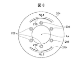
- FIG. 8 attached to the specification of the present application corresponds to FIG. 7 of Patent Document 2.
- FIG. 9 is a schematic side view for explaining the coating machine of Patent Document 2.
- reference numeral 200 indicates a coating machine of Patent Document 2.
- Reference numeral 202 is a bell. The bell 202 rotates in one direction about the axis Ax.
- Reference numeral 204 is an air ring member. The air ring member 204 is detachably attached to the coating machine main body 206 by a plurality of bolts 208 (FIG. 8).
- the plurality of bolts 208 are composed of a total of six bolts arranged at equal intervals on the same circumference centered on the axis Ax. By removing all the bolts 208, the air ring member 204 can be positioned at an arbitrary position rotationally displaced about the axis Ax.
- Patent Document 2 In the rotary atomization type electrostatic coating machine around 1983 when Patent Document 2 was filed, the rotation speed of the bell 202 was 10,000 rpm or less. Patent Document 2 describes that the rotation speed of the rotary atomizing electrostatic coating machine is 30,000 to 100,000 rpm, but at that time, such a high-speed rotating rotary atomizing electrostatic coating machine was not developed. From this fact, 30,000 to 100,000 rpm in Patent Document 2 is an erroneous description, and the correct value is 3,000 to 10,000 rpm.
- the air ring member 204 has a plurality of air holes 210 arranged on the same circle centered on the axis Ax.
- the plurality of air holes 210 discharge shaping air SA (FIG. 9).
- the plurality of air holes 210 form a first group No. 1 and a second group No. 2 that oppose each other in the radial direction on the same circumference centered on the axis Ax.
- the air ring member 204 is not provided with an air hole in the region between the first air hole group No. 1 and the second air hole group No. 2.
- the air ring member 204 includes first and second air hole groups No. 1 and No. 2 in the upper and lower regions. , There are no air holes in the left and right regions.
- Patent Document 2 discloses that a substantially elliptical coating pattern in which the upper and lower parts are crushed is generated by the first and second shaping airs SA (1) and SA (2) that oppose each other across the axis Ax. It is a suggestion. As described above, around 1983 when the application for Patent Document 2 was filed, the rotation speed of the bell 202 was 10,000 rpm or less. The amount of paint discharged at that time was generally about 300 cc / min.
- the electrostatic coating machine 200 disclosed in Patent Document 2 can position the air ring member 204 at an arbitrary position in which the air ring member 204 is rotationally displaced by removing the plurality of bolts 208.
- a pattern deformation ring is added as a modification of the embodiment, and the rotation amount of the pattern deformation ring is adjusted to obtain substantially the same effect as the rotation displacement of the air ring member 204.
- This proposal is to deal with the rotational displacement of the coating pattern about the axis Ax when the coating conditions are changed with the change of the type of paint.
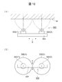
- FIG. 10 is a diagram for explaining a painting device called "twin bell".
- FIG. 10 (I) is a plan view of the twin bell coating apparatus 300 as viewed from above, and
- FIG. 10 (II) is a rear view.
- the twin bell coating apparatus 300 has a configuration in which two identical rotary atomizing electrostatic coating machines 302 (1) and 302 (2) are arranged on a common base 304.
- reference numeral W indicates an object to be coated (work).
- This twin bell painting device 300 is assembled to a painting robot or a reciprocating engine.
- the alignment directions of the two coating machines 302 (1) and 302 (2) are indicated by reference numerals X (FIG. 10 (I)).
- the twin bell coating apparatus 300 performs the coating operation while moving in the direction Y (FIG. 10 (II)) orthogonal to the alignment direction X of the two coating machines 302 (1) and 302 (2).
- the paint discharge amount of each of the coating machines 302 (1) and 302 (2) is about 300 cc / min. A large amount of liquid paint of about 600 cc / min. Can be applied to the paint. As a result, the coating processing efficiency can be improved.
- Patent Document 2 The inventors of the present application have adopted the technical idea disclosed in Patent Document 2 with the aim of achieving substantially the same coating processing efficiency as the twin bell coating apparatus 300 with one coating machine instead of the twin bell coating apparatus 300.
- the coating machine that is, the rotary atomization type electrostatic coating machine 200 described with reference to FIGS. 8 and 9, was manufactured and tested under the condition of a paint discharge rate of about 600 cc / min.
- this experiment was unsuccessful. That is, it was not possible to form a coating pattern having a substantially elliptical shape and a desired paint distribution under the coating conditions of a paint ejection amount of about 600 cc / min., Which is larger than that at the time when Patent Document 2 was filed. ..
- the rotation speed of the bell 202 was 20,000 to 30,000 rpm, which is generally used at present.
- the air hole is a straight hole, and shaping air is discharged straight from this straight air hole toward the front.
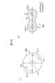
- FIG. 11 is a diagram for explaining the produced air ring member 400 and the coating pattern 420 generated by the air ring member 400.
- FIG. 11 (I) is a view of the air ring member 400 as viewed from the back.
- the air hole 410 seen in FIG. 11 (I) is shown by a solid line.
- the air ring member 400 includes first and second air hole groups No. 1 and No. 2 in the upper and lower regions on the same circumference, and the left and right regions. There are no air holes in.
- the plurality of air holes 410 included in the upper and lower groups No. 1 and No. 2 have the same twist angle. Further, the diameters of the plurality of air holes 410 are all the same.
- the twisted shaping air SA is discharged from each air hole 410.
- the terms "twisted angle” and “twisted” are the same as those disclosed in Patent Document 1. It means that it has an inclination angle in the circumferential direction with reference to the "straight hole” disclosed in Patent Document 2.
- the coating pattern 420 has a peanut-like outer contour. That is, the coating pattern 420 has a vertically crushed shape in which two circular portions 424 (1) and 424 (2) are connected by a relatively narrow connecting portion 426. This shape is preferable. However, the central portions 428 (1) and 428 (2) of the first and second circular portions 424 (1) and 424 (2) become the outer peripheral portions 430 (1), 430 (2) and the connecting portion 426. There was a new problem that the density of the paint was higher than that. This means that it is virtually impossible to make the paint adhering to the work a uniform film thickness.
- FIG. 12 schematically shows the captured image.
- FIG. 12 (I) is an image taken immediately after the paint adheres to the work. It can be seen that the liquid paint is concentrated on the two portions 440 (1) and 440 (2) separated from each other on the surface of the work.
- FIG. 12 (II) is an image taken 2-3 seconds after the paint adheres to the work. From this image, it can be seen that the paint adhesion region expands outward from the two paint concentrated portions 440 (1) and 440 (2).
- Reference numerals 442 (1) and 442 (2) indicate the outer peripheral portions generated by expanding the paint adhesion region outward from the two paint concentrated portions 440 (1) and 440 (2). Then, it was found that the coating pattern 420 of FIG. 11 (II) described above was finally generated by the adhesion region of the liquid paint. That is, the first and second central portions 428 (1) and 428 (2) of the coating pattern 420 (FIG. 11 (II)) become the paint concentrated portions 440 (1) and 440 (2) immediately after the paint adheres, respectively. It corresponds.
- the inventors of the present application understood that the series of captured images of the above high-speed camera teaches the following. That is, in a large amount of paint discharged at 600 cc / min., By adopting twisted shaping air, the coating pattern 420 can be deformed into a crushed shape (FIG. 11 (II)).
- this coating pattern 420 includes the first and second central portions 428 (1) and (2) having high paint densities, the coating film of the paint adhering to the work becomes non-uniform.
- the reference symbol “R” shown in FIG. 11 (I) indicates the direction of rotation of the bell.
- the coating pattern 420 is rotationally displaced in the same direction as the rotation direction R of the bell.
- the painting conditions were as follows. (i) Bell rotation speed: 20,000 rpm to 30,000 rpm. (ii) Air pressure of shaping air SA: 2.0Kgf / cm 2 . (iii) Paint discharge rate: 600 cc / min.
- the problem of rotational displacement of the coating pattern 420 does not need to be considered as a problem if the applicable paint is limited to one.
- the problem of rotational displacement is seen as a problem when applied to various paints.
- this problem can be solved by displacing the fixed position of the air ring member 400 around the axis Ax.
- FIG. 13 is a diagram corresponding to FIG.
- the characteristics of paint differ depending on the color of the paint.
- the electrostatic coating machine is generally controlled to change the bell rotation speed and the pressure of the shaping air according to the characteristics of the paint.
- experiments were conducted to change the bell speed and / or the pressure of the shaping air in order to investigate the adaptability to the change of the bell speed and the pressure of the shaping air.
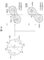
- the resulting coating pattern is shown in FIG. FIG. 14 (I) shows the coating pattern 420 (A) when the bell rotation speed is changed from 20,000 rpm to 30,000 rpm.
- FIG. 14 (II) shows the coating pattern 420 (B) when the pressure of the shaping air is changed from 2.0 Kgf / cm 2 to 3.0 Kgf / cm 2 while the bell rotation speed is maintained at 30,000 rpm. Note that FIG. 14 is a diagram corresponding to FIG.
- the twin bell coating apparatus 300 (FIG. 10) has the advantage of being able to improve the coating processing efficiency, as described above.
- the twin bell coating device 300 requires two electrostatic coating machines 302 (1) and 302 (2). If one coating machine can achieve coating with substantially the same quality as the twin bell coating apparatus 300, the cost of the coating machine, related peripheral equipment, and equipment including control equipment can be significantly reduced.
- the coating pattern 420 includes the central portions 428 (1) and 428 (2) having high paint densities at positions separated from each other.
- the coating pattern is rotationally displaced in response to the change.
- a main object of the present invention is a rotary atomization type electrostatic coating machine capable of generating a coating pattern having a crushed circular shape using shaping air and optimizing the coating distribution in the coating pattern.
- the purpose is to provide an airing member.
- a further object of the present invention is a rotary atomization type electrostatic coating machine capable of optimizing the paint distribution in the crushed coating pattern and suppressing the rotational displacement of the coating pattern even when applied to various paints.
- the purpose is to provide an air ring member.
- a further object of the present invention is to provide a rotary atomization type electrostatic coating machine that can be replaced with a twin bell coating device and an airing member thereof.
- a rotating atomizing head that emits liquid paint particles
- a plurality of mains constituting the first and second main groups arranged so as to oppose the radial direction on the first circumference centered on the rotation axis of the rotary atomizing head and having a first twist angle.
- a plurality of inner peripherals located on the inner peripheral side of the plurality of main air holes, arranged over the entire circumference on the second circumference centered on the axis of the rotary atomizing head, and having a second twist angle.
- Peripheral air hole and The outer peripheral side shaping air is discharged from the plurality of main air holes of the first and second main groups, and the outer peripheral side shaping air is discharged.
- the inner peripheral side shaping air is discharged from the plurality of inner peripheral side air holes, and the inner peripheral side shaping air is discharged.
- the inner peripheral side shaping air is stronger than the outer peripheral side shaping air
- the first twist angle of each of the main air holes is a twist angle opposite to the rotation direction of the rotary atomizing head
- the second twist angle of each of the inner peripheral side air holes is the rotary mist.
- the twist angle is the same as the direction of rotation of the head.
- the first twist angle of each of the main air holes is the twist angle in the same direction as the rotation direction of the rotary atomizing head
- the second twist angle of each of the inner peripheral side air holes is the rotary atomization. This is achieved by providing a rotary atomizing electrostatic coating machine characterized by a twist angle opposite to the direction of rotation of the head and an airing member included therein.
- the twisted outer peripheral side shaping air has the function of crushing the application pattern.
- the twisted inner peripheral side shaping air has a function of optimizing the paint distribution in the coating pattern and making the coating film of the paint adhering to the work uniform. Then, by twisting the outer peripheral side shaping air and the inner peripheral side shaping air in opposite directions, it is possible to obtain the effect of suppressing the rotational displacement of the coating pattern even when applied to various paints.
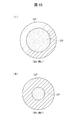
- the coating density of the central portion CP is low as compared with that of the central portion CP and the outer peripheral portion OP.
- the size of the central CP which has a relatively low paint density, changes depending on the strength of the shaping air.
- FIG. 15 (I) shows a coating pattern when the shaping air is weak
- FIG. 15 (II) shows a coating pattern when the shaping air is strong.
- the central CP expands (Fig. 15 (I)).
- the central CP becomes smaller (Fig. 15 (II)).
- the present invention is further characterized in that the strengths of the twisted shaping air inside and outside that are discharged diagonally forward from the air ring are different.
- the inner peripheral side shaping air is stronger than the outer peripheral side shaping air.
- the paint particles are conveyed toward the work by the strong propulsive force of the inner peripheral side shaping air, and the central portion CP having a low paint density is formed.
- the paint distribution in the coating pattern can be optimized.
- the circular coating pattern can be deformed into a crushed shape by the relatively weak outer peripheral side shaping air SA.
- the outer peripheral side shaping air and the inner peripheral side shaping air are twisted in relatively opposite directions in order to generate a coating pattern having a crushed circular shape and to optimize the paint distribution in the coating pattern. It was found that this is effective in suppressing the rotational displacement of the coating pattern. Specifically, it was found that one of the following two combinations is effective.
- the first twist angle of the outer peripheral side shaping air is the twist angle in the direction opposite to the rotation direction of the bell.
- the second twist angle of the inner peripheral side shaping air is the twist angle in the same direction as the rotation direction of the bell.
- the first twist angle of the outer peripheral side shaping air is the twist angle in the same direction as the rotation direction of the bell.
- the second twist angle of the inner peripheral side shaping air is the twist angle in the direction opposite to the rotation direction of the bell.
- the first twist angle of the outer peripheral side shaping air is the twist angle in the direction opposite to the rotation direction of the bell.
- the second twist angle of the inner peripheral side shaping air is the twist angle in the direction opposite to the rotation direction of the bell.
- ⁇ Fourth combination (1)
- the first twist angle of the outer peripheral side shaping air is the twist angle in the same direction as the rotation direction of the bell.
- the second twist angle of the inner peripheral side shaping air is the twist angle in the same direction as the rotation direction of the bell.
- FIG. 7 is a view corresponding to FIG.
- FIG. 7 of Patent Document 2 is a front view of an airing member incorporated in a conventional coating machine that generates an elliptical coating pattern by shaping air.
- FIG. 8 is a diagram for explaining a configuration of a conventional coating machine incorporating the illustrated air ring member.
- (I) is a diagram for explaining the arrangement of the two coating machines of the twin bell coating device, and
- (II) is a diagram for explaining the moving direction of the twin bell coating device. It is a figure for demonstrating that a coating pattern of a crushed circle shape can be generated by using twisted shaping air
- (I) is a rear view of the used air ring member
- (II) is a coating pattern. It is a front view of.
- FIG. 11 is a diagram for explaining an image captured by a high-speed camera in order to analyze the problem of the illustrated coating pattern, and (I) shows a state immediately after the paint adheres to the work, and (II). ) Indicates the state after 2-3 seconds. It is a figure for demonstrating the state in which the air ring member was installed at the position which was rotationally displaced in order to correct the rotational displacement of the coating pattern generated by using the twisted shaping air, and is the figure corresponding to FIG.
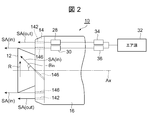
- FIG. 1 and 2 are views for explaining the rotary atomization type electrostatic coating machine 10 of the embodiment.
- the liquid paint is supplied to the central portion of the bell 12. Further, a negative high voltage is applied to the bell 12.
- the coating machine 10 discharges the charged paint particles from the outer peripheral edge of the bell 12 to the outside by rotating the bell 12 at high speed by an air motor (not shown).
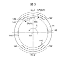
- FIG. 3 is a front view of the air ring member 14 as viewed from the front.
- the air ring member 14 has a pair of air holes No. 1 and No. 2 located on the first circumference centered on the axis Ax and opposed to each other with the bell rotation axis Ax in between. .. That is, the first and second main groups No. 1 and No. 2 are located opposite to each other in the radial direction.
- the first and second main groups No. 1 and No. 2 are composed of a plurality of first air holes 142, and the outer peripheral side shaping air SA (out) is discharged from the plurality of first air holes 142. ..
- the air ring member 14 also has a plurality of second air holes 146 on the inner peripheral side of the plurality of first air holes 142.
- the plurality of second air holes that is, the inner peripheral side air holes 146 are arranged at equal intervals over the entire circumference on the second circumference centered on the bell axis Ax.
- the inner peripheral side shaping air SA (in) is discharged from the inner peripheral side air hole 146.
- the inner peripheral side shaping air SA (in) is stronger than the outer peripheral side shaping air SA (out).
- the plurality of first air holes constituting the first and second main groups No. 1 and No. 2 related to the outer peripheral side shaping air SA (out), that is, the outer peripheral side air holes 142 are all circular holes having the same diameter in cross section. be. Further, the plurality of second air holes that generate the inner peripheral side shaping air SA (in), that is, the inner peripheral side air holes 146 are all circular holes having the same diameter in cross section.
- the outer peripheral side shaping air SA (out) is directed toward a position away from the outer peripheral edge of the bell 12.
- the inner peripheral side shaping air SA (in) is directed toward the outer peripheral edge of the bell 12.
- the inner peripheral side shaping air SA (in) may be directed to a position away from the outer peripheral edge of the bell 12. This separation distance is preferably in the range of about 5 mm from the outer peripheral edge of the bell 12.
- the outer peripheral side shaping air SA (out) and the inner peripheral side shaping air SA (in) are twisted in relatively opposite directions. More specifically, with reference to FIGS. 1 and 3, the outer peripheral side shaping air SA (out) is twisted in the direction opposite to the rotation direction R of the bell 12. On the other hand, the inner peripheral side shaping air SA (in) is twisted in the same direction as the rotation direction R of the bell.
- the outer peripheral side shaping air SA (out), that is, the first twist angle ⁇ out (FIG. 1) of the outer peripheral side air hole 142 is 45 ° in the direction opposite to the rotation direction R of the bell 12.
- the twist angle ⁇ out of the outer peripheral air hole 142 is not limited to 45 °.
- the first twist angle ⁇ out may be 10 ° to 60 °, preferably 30 to 50 °.
- the inner peripheral side shaping air SA (in) that is, the second twist angle ⁇ in of the inner peripheral side air hole 146 is 45 ° in the same direction as the rotation direction R of the bell 12 (FIGS. 1 and 2).
- the twist angle ⁇ in of the inner peripheral side air hole 146 is not limited to 45 °.
- the second twist angle ⁇ in may be 10 ° to 60 °, preferably 30 to 50 °.
- the inner peripheral side shaping air SA (in) is stronger than the outer peripheral side shaping air SA (out).
- compressed air is supplied to the outer peripheral side air hole 142 from the outer peripheral side air chamber 28.
- Compressed air is supplied from the inner peripheral side air chamber 30 to the inner peripheral side air hole 146.
- Compressed air is supplied from the common compressed air source 32 to the outer peripheral side air chamber 28 and the inner peripheral side air chamber 30 through the first and second air pressure adjusting units 34 and 36.
- the pressure of the compressed air supplied to the outer peripheral side and inner peripheral side air chambers 28 and 30 can be controlled by the outer peripheral side and inner peripheral side air pressure adjusting units 34 and 36.
- the inner and outer air holes 142 and 146 have the same diameter, specifically 1.0 mm. Then, the pressure of the compressed air supplied to the inner peripheral side air chamber 30 is set to a value higher than that of the outer peripheral side air chamber 28.
- the diameter of the bell 12 is 60 mm.
- the amount of paint discharged, the number of revolutions of the bell, and the pressure of the compressed air supplied to the outer peripheral side and inner peripheral side air chambers 28 and 30 can be controlled by a control signal from a control panel (not shown).
- the rotation speed of the bell 12 was controlled in the range of 30,000 to 40,000 rpm, and the pressure of the outer peripheral side shaping air SA (out) was fixed at 0.5 Kgf / cm 2.
- the pressure of the inner peripheral side shaping air SA (in) was controlled in the range of 1.5 to 2.0 Kgf / cm 2 which is higher than the outer peripheral side shaping air SA (out).
- the coating pattern 40 shown in FIG. 4 could be generated.
- the coating pattern 40 had an elliptical outer contour, and the width in the major axis direction was 630 to 650 mm.
- the coating pattern 40 was composed of an outer peripheral portion OP in which the amount of paint was large and the paint density was substantially uniform, and an inner peripheral portion CP in which the paint was thin. As a result, a coating film having a uniform film thickness could be formed on the work surface.
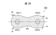
- the whiskers 42 were found in the coating pattern 420 generated by the conventional coating machine 200 described with reference to FIGS. 8 and 9.
- the application pattern 420 in which the whiskers 42 are generated is shown in FIG.
- the whiskers 42 appeared at the four corners of the application pattern 420.
- the inventors of the present application have examined the airing member 14 (FIG. 3) of the first embodiment with the aim of realizing a more preferable coating pattern without a whiskers 42.
- the air holes are completely present in the region sandwiched between the first and second main groups No. 1 and No. 2 composed of the plurality of outer peripheral side air holes 142.
- the inventors of the present application have an extreme configuration between the region where the air holes 142 of the first main group No. 1 and the second main group No. 2 exist and the region where the air holes 142 do not exist at all. It was speculated that the difference was the cause of the whiskers 42. Based on this inference, additional air holes are provided in each transient region at both ends of the first main group No. 1 and the second main group No. 2, and relatively weak air is discharged from the additional air holes. I came up with that.
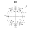
- FIG. 5 shows the air ring member 50 of the second embodiment.
- This FIG. 5 corresponds to FIG. Therefore, the air ring member 50 of the second embodiment will be described using the reference reference numerals used in FIG.
- the air ring member 50 of the second embodiment has a total of four transient groups 152 that are continuous at both ends of the first main group No. 1 and the second main group No. 2.
- the transient group 152 is composed of a plurality of transient air holes 154, and compressed air is supplied from the outer peripheral side air chamber 28 to the plurality of transient air holes 154.
- the air discharged from the transient group 152 constitutes a part of the outer peripheral side shaping air SA (out).
- the plurality of transient air holes 154 are arranged at equal intervals on the first circumference common to the outer peripheral side air holes 142 of the first main group No. 1 and the second main group No. 2.
- Each transient air hole 154 is the same as the outer peripheral side air hole 142 in that it has a first twist angle of 45 ° in the direction opposite to the rotation direction R of the bell 12.
- the air discharged from the plurality of transient air holes 154 is the first and first. It is weaker than the air discharged from the plurality of main air holes 142 constituting the main groups No. 1 and No. 2 of 2.
- the outer peripheral air chamber 28 (FIG. 2) for supplying air to the main air hole 142 is used to supply air from the outer peripheral air chamber 28 to the transient air hole 154
- the main air chamber 28 is used.
- the diameter of the transient air hole 154 may be smaller than that of the air hole 142.
- the diameter of the transient air hole 154 may be set to, for example, 0.8 mm.
- the plurality of transient air holes 154 may all be formed of holes having the same diameter.
- the diameter of each of the plurality of transient air holes 154 constituting the transient group 152 gradually or gradually increases as it approaches the end of the first main group No. 1 or the second main group No. 2. It may be designed to have a large diameter.
- a plurality of transient air holes 154 constituting each transient group 152 are composed of two types of holes having a diameter of 0.8 mm and a diameter of 0.6 mm, and the first main group No. 1 or the second is formed.
- the transient air hole 154 close to the main group No. 2 is composed of air holes with a diameter of 0.8 mm, and the transient air hole 154 far from the first main group No. 1 or the second main group No. 2 is 0.6 mm in diameter. It may be composed of the air holes of.
- FIG. 6 shows the air ring member 60 of the third embodiment.
- the air ring member 60 is also a modified example of the air ring member 50 of the second embodiment.
- the air ring member 60 of the third embodiment has two transient groups 152 extending from both ends of the first main group No. 1 and two transient groups extending from both ends of the second main group. It has two complementary groups 162, each of which is continuous with 152.
- the plurality of complementary air holes 164 constituting each complementary group 162 are the main air holes 142 of the first main group No. 1 and the second main group No. 2 and the transient air holes 154 of the transient group 152 adjacent thereto. They are arranged at equal intervals on the first circumference in common with. Compressed air is supplied from the outer peripheral side air chamber 28 to the plurality of complementary air holes 164.
- the air discharged from the complement group 162 constitutes a part of the outer peripheral side shaping air.
- the air ring member 60 of the third embodiment can discharge the outer peripheral side shaping air SA (out) from the plurality of complementary air holes 164, the main air holes 142, and the transient air holes 154 over the entire circumference.
- the complementary air hole 164 is the same as the main air hole 142 and the transient air hole 154 in that it has a first twist angle of 45 ° in the direction opposite to the rotation direction R of the bell 12.
- the air discharged from the plurality of complementary air holes 164 is weaker than the air discharged from the plurality of transient air holes 154.
- air is supplied from the outer peripheral side air chamber 28 to the transient air hole 154 and the complementary air hole 164 by using the outer peripheral side air chamber 28 (FIG. 2) that supplies air to the main air hole 142. If this is the case, the diameter of the complementary air hole 164 may be smaller than that of the transient air hole 154.
- the diameter of the main air hole 142 was 1 mm
- the diameter of the transient air hole 154 was 0.8 mm
- the diameter of the complementary air hole 164 was 0.5 mm.
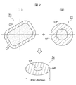
- FIG. 7 shows the action of the outer peripheral side shaping air SA (out) and the inner peripheral side shaping air SA (in) in the rotary atomization type electrostatic coating machine incorporating the air ring member 60 (FIG. 6) of the third embodiment. It is a figure for conceptually explaining that an elliptical coating pattern 40 is formed by superimposing the action of).
- FIG. 7 (I) shows a first pattern 70 formed only by the outer peripheral side shaping air SA (out) without the inner peripheral side shaping air SA (in).
- the outer contour of the first pattern 70 is substantially rectangular.
- FIG. 7 (II) shows a second pattern 72 formed only by the inner peripheral side shaping air SA (in) without the outer peripheral side shaping air SA (out).
- the outer contour of the second pattern 72 is circular.
- the coating machine 10 incorporating the air ring member 60 of the third embodiment can achieve the same coating quality as the twin bell coating apparatus 300 (FIG. 10).
- the rotary atomization type electrostatic coating machine according to the present invention is effective for the following coating conditions.
- Bell rotation speed 20,000-45,000 rpm. Preferably 30,000-40,000 rpm.
- Paint discharge rate 200 to 600 cc / min. Preferably 300-500 cc / min.
- Applicable paints water-based and oil-based paints. Metallic paint, clear paint, solid paint.
Landscapes
- Electrostatic Spraying Apparatus (AREA)
- Nozzles (AREA)
Abstract
Description
(i)ベルの回転数:20,000rpm~30,000rpm。
(ii)シェーピングエアSAのエア圧:2.0Kgf/cm2。
(iii)塗料吐出量:600cc/min.。
液体塗料粒子を放出する回転霧化頭と、
該回転霧化頭の回転軸線を中心とする第1の円周上の径方向に対抗して配置された第1、第2の主群を構成し且つ第1の捻り角を有する複数の主エア孔と、
該複数の主エア孔の内周側に位置し、前記回転霧化頭の軸線を中心とした第2の円周上の全周に亘って配置され且つ第2の捻り角を有する複数の内周側エア孔と、
前記第1、第2の主群の複数の主エア孔から外周側シェーピングエアが吐出され、
前記複数の内周側エア孔から内周側シェーピングエアが吐出され、
該内周側シェーピングエアが前記外周側シェーピングエアよりも強く、
前記主エア孔の各々の前記第1の捻り角が前記回転霧化頭の回転方向とは逆方向の捻り角であり且つ前記内周側エア孔の各々の第2の捻り角が前記回転霧化頭の回転方向と同一方向の捻り角であり、
又は、
前記主エア孔の各々の前記第1の捻り角が前記回転霧化頭の回転方向と同一方向の捻り角であり且つ前記内周側エア孔の各々の第2の捻り角が前記回転霧化頭の回転方向と逆方向の捻り角であることを特徴とする回転霧化式静電塗装機及びこれに含まれるエアリング部材を提供することにより達成される。
(1)外周側シェーピングエアの第1の捻り角がベルの回転方向と逆方向の捻り角である。
(2)内周側シェーピングエアの第2の捻り角がベルの回転方向と同じ方向の捻り角である。
<第2の組み合わせ>
(1)外周側シェーピングエアの第1の捻り角がベルの回転方向と同じ方向の捻り角である。
(2)内周側シェーピングエアの第2の捻り角がベルの回転方向と逆方向の捻り角である。
(1)外周側シェーピングエアの第1の捻り角がベルの回転方向と逆方向の捻り角である。
(2)内周側シェーピングエアの第2の捻り角がベルの回転方向と逆方向の捻り角である。
<第4の組み合わせ>
(1)外周側シェーピングエアの第1の捻り角がベルの回転方向と同じ方向の捻り角である。
(2)内周側シェーピングエアの第2の捻り角がベルの回転方向と同じ方向の捻り角である。
図1、図2は実施例の回転霧化式静電塗装機10を説明するための図である。図示の塗装機10において、液体塗料はベル12の中心部分に供給される。また、ベル12にはマイナスの高電圧が印可される。塗装機10は、図外のエアモータによってベル12を高速回転させることにより、帯電した塗料粒子をベル12の外周縁から外方に放出する。
(1)ベル回転数:20,000~45,000rpm。好ましくは30,000~40,000rpm。
(2)塗料吐出量:200~600cc/min.。好ましくは300~500cc/min.。
(3)適用可能な塗料:水性及び油性塗料。メタリック塗料、クリア塗料、ソリッド塗料。
12 ベル
14 エアリング部材
142 外周側シェーピングエアを吐出する第1エア孔(外周側エア孔)
No.1 外周側エア孔の第1の主群
No.2 外周側エア孔の第2の主群
146 内周側シェーピングエアを吐出する第2エア孔(内周側エア孔)
16 塗装機本体
28 外周側エア孔に圧縮エアを供給する外周側エア室
30 内周側エア孔に圧縮エアを供給する内周側エア室
34 外周側エア室に供給する圧縮エアのエア圧を調整する外周側ユニット
36 内周側エア室に供給する圧縮エアのエア圧を調整する内周側ユニット
40 塗布パターン
SA(in) 内周側シェーピングエア
SA(out) 外周側シェーピングエア
θout 外周側エア孔の第1の捻り角
θin 内周側エア孔の第2の捻り角
152 過渡群
154 過渡エア孔
162 補完群
164 補完エア孔
Claims (18)
- 液体塗料粒子を放出する回転霧化頭と、
該回転霧化頭の回転軸線を中心とする第1の円周上の径方向に対抗して配置された第1、第2の主群を構成し且つ第1の捻り角を有する複数の主エア孔と、
該複数の主エア孔の内周側に位置し、前記回転霧化頭の軸線を中心とした第2の円周上の全周に亘って配置され且つ第2の捻り角を有する複数の内周側エア孔と、
前記第1、第2の主群の複数の主エア孔から外周側シェーピングエアが吐出され、
前記複数の内周側エア孔から内周側シェーピングエアが吐出され、
該内周側シェーピングエアが前記外周側シェーピングエアよりも強く、
前記主エア孔の各々の前記第1の捻り角が前記回転霧化頭の回転方向とは逆方向の捻り角であり且つ前記内周側エア孔の各々の第2の捻り角が前記回転霧化頭の回転方向と同一方向の捻り角であり、
又は、
前記主エア孔の各々の前記第1の捻り角が前記回転霧化頭の回転方向と同一方向の捻り角であり且つ前記内周側エア孔の各々の第2の捻り角が前記回転霧化頭の回転方向と逆方向の捻り角であることを特徴とする回転霧化式静電塗装機。
- 前記回転霧化頭の回転数が20,000~45,000rpmである、請求項1に記載の回転霧化式静電塗装機。
- 塗料吐出量が200~600cc/min.である、請求項1に記載の回転霧化式静電塗装機。
- 前記複数の主エア孔に圧縮エアを供給する第1エア室と、
該第1エア室から独立し且つ前記内周側エア孔に圧縮エアを供給する第2エア室とを有し、
前記第2エア室の圧縮エアの圧力が前記第1エア室の圧縮エアの圧力よりも高い、請求項1に記載の回転霧化式静電塗装機。
- 前記主エア孔の各々の前記第1の捻り角が前記回転霧化頭の回転方向とは逆方向の捻り角であり且つ前記内周側エア孔の各々の第2の捻り角が前記回転霧化頭の回転方向と同一方向の捻り角である、請求項1に記載の回転霧化式静電塗装機。
- 前記内周側シェーピングエアの前記第2の捻り角が10°~60°である、請求項1に記載の回転霧化式静電塗装機。
- 前記内周側シェーピングエアの前記第2の捻り角が30°~50°である、請求項1に記載の回転霧化式静電塗装機。
- 前記外周側シェーピングエアの前記第1の捻り角が10°~60°である、請求項1に記載の回転霧化式静電塗装機。
- 前記外周側シェーピングエアの前記第1の捻り角が30°~50°である、請求項1に記載の回転霧化式静電塗装機。
- 前記内周側シェーピングエアが前記回転霧化頭の外周縁又はその径方向外方の近傍に指向されている、請求項1に記載の回転霧化式静電塗装機。
- 前記外周側シェーピングエアが前記回転霧化頭の外周縁から離間した位置に向けて指向されている、請求項10に記載の回転霧化式静電塗装機。
- 前記第1、第2の主群に隣接し且つ前記第1の円周上に配置された複数の過渡エア孔からなる過渡群を更に有し、
前記複数の過渡エア孔が前記主エア孔と同じ方向の且つ同じ捻り角を有し、
該複数の過渡エア孔から吐出されるエアが前記外周側シェーピングエアの一部を構成し、
該過渡エア孔の各々から吐出されるエアが前記主エア孔の各々から吐出されるエアよりも弱い、請求項1に記載の回転霧化式静電塗装機。
- 前記第1、第2の主群に隣接し且つ前記第1の円周上に配置された複数の過渡エア孔からなる過渡群を更に有し、
前記複数の過渡エア孔が前記主エア孔と同じ方向の且つ同じ捻り角を有し、
該複数の過渡エア孔から吐出されるエアが前記外周側シェーピングエアの一部を構成し、
前記第1エア室から前記過渡エア孔に圧縮エアが供給され、
前記各過渡エア孔の直径が前記主エア孔の直径よりも小さい、請求項4に記載の回転霧化式静電塗装機。
- 前記第1の主群に隣接した過渡群と、前記第2の主群に隣接した過渡群との間に位置し且つ前記第1の円周上に配置された複数の補完エア孔からなる一対の補完群を有し、
前記複数の補完エア孔が前記過渡エア孔と同じ方向の且つ同じ捻り角を有し、
該複数の補完エア孔から吐出されるエアが前記外周側シェーピングエアの一部を構成し、
該補完エア孔の各々から吐出されるエアが前記過渡エア孔の各々から吐出されるエアよりも弱い、請求項13に記載の回転霧化式静電塗装機。
- 前記第1の主群に隣接した過渡群と、前記第2の主群に隣接した過渡群との間に位置し且つ前記第1の円周上に配置された複数の補完エア孔からなる一対の補完群を有し、
前記複数の補完エア孔が前記過渡エア孔と同じ方向の且つ同じ捻り角を有し、
該複数の補完エア孔から吐出されるエアが前記外周側シェーピングエアの一部を構成し、
前記第1エア室から前記補完エア孔に圧縮エアが供給され、
前記各補完エア孔の直径が前記過渡エア孔の直径よりも小さい、請求項14に記載の回転霧化式静電塗装機。
- 請求項1~11のいずれか一項に記載の回転霧化式静電塗装機の一部を構成し、
前記複数の主エア孔と、前記複数の内周側エア孔とを有するエアリング部材。
- 前記第1、第2の主群に隣接して位置し且つ前記第1の円周上に配置された複数の過渡エア孔からなる過渡群を更に有し、
前記複数の過渡エア孔が前記主エア孔と同じ方向の且つ同じ捻り角を有し、
該複数の過渡エア孔の直径が前記主エア孔の直径よりも小さい、請求項16に記載のエアリング部材。
- 前記第1の主群に隣接した過渡群と、前記第2の主群に隣接した過渡群との間に位置し且つ前記第1の円周上に配置された複数の補完エア孔からなる一対の補完群を有し、
前記複数の補完エア孔が前記過渡エア孔と同じ方向の且つ同じ捻り角を有し、
該複数の補完エア孔の直径が前記過渡エア孔の直径よりも小さい、請求項17に記載のエアリング部材。
Priority Applications (3)
| Application Number | Priority Date | Filing Date | Title |
|---|---|---|---|
| CN202080098419.9A CN115297967B (zh) | 2020-03-10 | 2020-12-25 | 旋转雾化式静电涂装机及其空气环部件 |
| JP2022505785A JP7389890B2 (ja) | 2020-03-10 | 2020-12-25 | 回転霧化式静電塗装機及びそのエアリング部材 |
| BR112022015366A BR112022015366A2 (pt) | 2020-03-10 | 2020-12-25 | Aparelho de pintura eletrostática do tipo com atomização rotacional e membro de ventilação para a mesmo |
Applications Claiming Priority (2)
| Application Number | Priority Date | Filing Date | Title |
|---|---|---|---|
| JP2020-041374 | 2020-03-10 | ||
| JP2020041374 | 2020-03-10 |
Publications (1)
| Publication Number | Publication Date |
|---|---|
| WO2021181833A1 true WO2021181833A1 (ja) | 2021-09-16 |
Family
ID=77671559
Family Applications (1)
| Application Number | Title | Priority Date | Filing Date |
|---|---|---|---|
| PCT/JP2020/048928 Ceased WO2021181833A1 (ja) | 2020-03-10 | 2020-12-25 | 回転霧化式静電塗装機及びそのエアリング部材 |
Country Status (4)
| Country | Link |
|---|---|
| JP (1) | JP7389890B2 (ja) |
| CN (1) | CN115297967B (ja) |
| BR (1) | BR112022015366A2 (ja) |
| WO (1) | WO2021181833A1 (ja) |
Citations (7)
| Publication number | Priority date | Publication date | Assignee | Title |
|---|---|---|---|---|
| JPH0884941A (ja) * | 1994-07-22 | 1996-04-02 | Nissan Motor Co Ltd | 回転霧化静電塗装方法および装置 |
| JPH0899052A (ja) * | 1994-09-29 | 1996-04-16 | Abb Ransburg Kk | 回転霧化頭型塗装装置 |
| JP2008093521A (ja) * | 2006-10-06 | 2008-04-24 | Ransburg Ind Kk | 回転式静電塗装装置 |
| JP2009214065A (ja) * | 2008-03-12 | 2009-09-24 | Ransburg Ind Kk | 回転式静電塗装装置及び塗装パターン制御方法 |
| JP2011524801A (ja) * | 2008-06-12 | 2011-09-08 | デュール システムズ ゲゼルシャフト ミット ベシュレンクテル ハフツング | 汎用アトマイザ |
| JP2016150265A (ja) * | 2015-02-16 | 2016-08-22 | トヨタ自動車株式会社 | 回転霧化型静電塗装機及びそのシェーピングエアリング |
| JP2018161642A (ja) * | 2017-03-27 | 2018-10-18 | トヨタ車体株式会社 | 回転霧化型静電塗装機及びそのシェーピングエアリング |
Family Cites Families (5)
| Publication number | Priority date | Publication date | Assignee | Title |
|---|---|---|---|---|
| JPS6054754A (ja) * | 1983-09-06 | 1985-03-29 | Nippon Ranzubaagu Kk | 静電噴霧装置 |
| DE102007006547B4 (de) * | 2007-02-09 | 2016-09-29 | Dürr Systems GmbH | Lenkluftring und entsprechendes Beschichtungsverfahren |
| JP5149566B2 (ja) * | 2007-08-29 | 2013-02-20 | 旭サナック株式会社 | 塗装ガン |
| JP2011230013A (ja) * | 2010-04-23 | 2011-11-17 | Asahi Sunac Corp | 回転霧化塗装機 |
| JP5684672B2 (ja) * | 2011-08-12 | 2015-03-18 | 本田技研工業株式会社 | 塗装方法及び塗装装置 |
-
2020
- 2020-12-25 BR BR112022015366A patent/BR112022015366A2/pt active IP Right Grant
- 2020-12-25 JP JP2022505785A patent/JP7389890B2/ja active Active
- 2020-12-25 CN CN202080098419.9A patent/CN115297967B/zh active Active
- 2020-12-25 WO PCT/JP2020/048928 patent/WO2021181833A1/ja not_active Ceased
Patent Citations (7)
| Publication number | Priority date | Publication date | Assignee | Title |
|---|---|---|---|---|
| JPH0884941A (ja) * | 1994-07-22 | 1996-04-02 | Nissan Motor Co Ltd | 回転霧化静電塗装方法および装置 |
| JPH0899052A (ja) * | 1994-09-29 | 1996-04-16 | Abb Ransburg Kk | 回転霧化頭型塗装装置 |
| JP2008093521A (ja) * | 2006-10-06 | 2008-04-24 | Ransburg Ind Kk | 回転式静電塗装装置 |
| JP2009214065A (ja) * | 2008-03-12 | 2009-09-24 | Ransburg Ind Kk | 回転式静電塗装装置及び塗装パターン制御方法 |
| JP2011524801A (ja) * | 2008-06-12 | 2011-09-08 | デュール システムズ ゲゼルシャフト ミット ベシュレンクテル ハフツング | 汎用アトマイザ |
| JP2016150265A (ja) * | 2015-02-16 | 2016-08-22 | トヨタ自動車株式会社 | 回転霧化型静電塗装機及びそのシェーピングエアリング |
| JP2018161642A (ja) * | 2017-03-27 | 2018-10-18 | トヨタ車体株式会社 | 回転霧化型静電塗装機及びそのシェーピングエアリング |
Also Published As
| Publication number | Publication date |
|---|---|
| JPWO2021181833A1 (ja) | 2021-09-16 |
| CN115297967A (zh) | 2022-11-04 |
| CN115297967B (zh) | 2024-07-26 |
| JP7389890B2 (ja) | 2023-11-30 |
| BR112022015366A2 (pt) | 2022-09-27 |
Similar Documents
| Publication | Publication Date | Title |
|---|---|---|
| US5078321A (en) | Rotary atomizer cup | |
| RU2502566C2 (ru) | Роторный распылитель и способ распыления материала покрытия при помощи такого роторного распылителя | |
| US9295999B2 (en) | Rotary atomizing painting device | |
| EP3417946B1 (en) | Electrostatic coater | |
| EP2905082B1 (en) | Bell cup for rotary atomizing type electrostatic coating device | |
| JP4385151B2 (ja) | 塗装方法及び塗装機 | |
| US11351559B2 (en) | Rotary atomization head and coating device | |
| JPH0899052A (ja) | 回転霧化頭型塗装装置 | |
| CN105709954B (zh) | 喷头和具有这种喷头的旋转式喷雾器 | |
| JPH0884941A (ja) | 回転霧化静電塗装方法および装置 | |
| JP2008093521A (ja) | 回転式静電塗装装置 | |
| WO2021181833A1 (ja) | 回転霧化式静電塗装機及びそのエアリング部材 | |
| US5954275A (en) | Rotary atomizing electrostatic coating apparatus | |
| CN115400893A (zh) | 旋转钟形雾化器成形空气配置和空气帽装置 | |
| CN114762843A (zh) | 旋转雾化式涂装装置 | |
| JP2013166113A (ja) | 回転霧化式静電塗装機及び回転霧化頭 | |
| JP5684672B2 (ja) | 塗装方法及び塗装装置 | |
| JP6973356B2 (ja) | ベル型塗装装置 | |
| JPH0833859A (ja) | 回転霧化静電塗装装置 | |
| JP6235963B2 (ja) | 回転霧化式静電塗装機 | |
| JP2747439B2 (ja) | 静電塗装装置 | |
| CN115121387A (zh) | 旋转雾化型涂装装置和旋转平衡调整方法 | |
| US12478991B2 (en) | Rotary atomizing coating device that includes a plurality of through holes that extend in a radial direction in a side surface portion of the rotary atomizing coating device | |
| US20220362787A1 (en) | Rotary atomization type painting apparatus | |
| JPS58104656A (ja) | 回転霧化静電塗装装置 |
Legal Events
| Date | Code | Title | Description |
|---|---|---|---|
| 121 | Ep: the epo has been informed by wipo that ep was designated in this application |
Ref document number: 20923979 Country of ref document: EP Kind code of ref document: A1 |
|
| REG | Reference to national code |
Ref country code: BR Ref legal event code: B01A Ref document number: 112022015366 Country of ref document: BR |
|
| ENP | Entry into the national phase |
Ref document number: 2022505785 Country of ref document: JP Kind code of ref document: A |
|
| ENP | Entry into the national phase |
Ref document number: 112022015366 Country of ref document: BR Kind code of ref document: A2 Effective date: 20220803 |
|
| NENP | Non-entry into the national phase |
Ref country code: DE |
|
| 122 | Ep: pct application non-entry in european phase |
Ref document number: 20923979 Country of ref document: EP Kind code of ref document: A1 |