WO2021181807A1 - 車両用電動パーキングブレーキ装置 - Google Patents
車両用電動パーキングブレーキ装置 Download PDFInfo
- Publication number
- WO2021181807A1 WO2021181807A1 PCT/JP2020/047371 JP2020047371W WO2021181807A1 WO 2021181807 A1 WO2021181807 A1 WO 2021181807A1 JP 2020047371 W JP2020047371 W JP 2020047371W WO 2021181807 A1 WO2021181807 A1 WO 2021181807A1
- Authority
- WO
- WIPO (PCT)
- Prior art keywords
- parking brake
- current
- electric motor
- current value
- operating position
- Prior art date
- Legal status (The legal status is an assumption and is not a legal conclusion. Google has not performed a legal analysis and makes no representation as to the accuracy of the status listed.)
- Ceased
Links
Images



Classifications
-
- B—PERFORMING OPERATIONS; TRANSPORTING
- B60—VEHICLES IN GENERAL
- B60T—VEHICLE BRAKE CONTROL SYSTEMS OR PARTS THEREOF; BRAKE CONTROL SYSTEMS OR PARTS THEREOF, IN GENERAL; ARRANGEMENT OF BRAKING ELEMENTS ON VEHICLES IN GENERAL; PORTABLE DEVICES FOR PREVENTING UNWANTED MOVEMENT OF VEHICLES; VEHICLE MODIFICATIONS TO FACILITATE COOLING OF BRAKES
- B60T13/00—Transmitting braking action from initiating means to ultimate brake actuator with power assistance or drive; Brake systems incorporating such transmitting means, e.g. air-pressure brake systems
- B60T13/74—Transmitting braking action from initiating means to ultimate brake actuator with power assistance or drive; Brake systems incorporating such transmitting means, e.g. air-pressure brake systems with electrical assistance or drive
-
- B—PERFORMING OPERATIONS; TRANSPORTING
- B60—VEHICLES IN GENERAL
- B60T—VEHICLE BRAKE CONTROL SYSTEMS OR PARTS THEREOF; BRAKE CONTROL SYSTEMS OR PARTS THEREOF, IN GENERAL; ARRANGEMENT OF BRAKING ELEMENTS ON VEHICLES IN GENERAL; PORTABLE DEVICES FOR PREVENTING UNWANTED MOVEMENT OF VEHICLES; VEHICLE MODIFICATIONS TO FACILITATE COOLING OF BRAKES
- B60T8/00—Arrangements for adjusting wheel-braking force to meet varying vehicular or ground-surface conditions, e.g. limiting or varying distribution of braking force
- B60T8/17—Using electrical or electronic regulation means to control braking
-
- H—ELECTRICITY
- H02—GENERATION; CONVERSION OR DISTRIBUTION OF ELECTRIC POWER
- H02P—CONTROL OR REGULATION OF ELECTRIC MOTORS, ELECTRIC GENERATORS OR DYNAMO-ELECTRIC CONVERTERS; CONTROLLING TRANSFORMERS, REACTORS OR CHOKE COILS
- H02P3/00—Arrangements for stopping or slowing electric motors, generators, or dynamo-electric converters
- H02P3/06—Arrangements for stopping or slowing electric motors, generators, or dynamo-electric converters for stopping or slowing an individual dynamo-electric motor or dynamo-electric converter
Definitions
- the present invention has a parking brake lever that enables rotation between an operating position for obtaining a parking brake state and a non-operating position for releasing the parking brake state, and is elastically urged toward the non-operating position side;
- the parking brake is capable of switching between a normal rotation state in which the parking brake lever exerts power to move the parking brake lever from the non-operating position to the operating position and a reverse rotation state when the parking brake lever is returned from the operating position to the non-operating position side.
- An electric actuator having an electric motor connected to a lever and capable of applying a load to the electric motor after a state in which the load of the electric motor becomes unloaded at the time of reversal of the electric motor;
- the present invention relates to an electric parking brake device for a vehicle, comprising: a control unit for controlling the operation of the electric motor; and a current detecting means for detecting an energizing current to the electric motor.
- the parking brake lever is moved to the operating position by the operation of the electric actuator to obtain the parking brake state, and the parking braking force is released according to the operation of the electric actuator so as to move the parking brake lever to the non-operating position.
- An electric parking brake device for a vehicle is known in Patent Document 1.
- the slope of the current value also fluctuates due to noise due to various electrical factors and mechanical factors (for example, external voltage fluctuation, motor internal structure, etc.), and in the above-mentioned Patent Document 1 disclosure, such fluctuation. There is a possibility that the operation stop of the electric motor may be erroneously accelerated due to the above.
- the present invention has been made in view of such circumstances, and is an electric parking brake device for a vehicle that enables the operation of the electric motor to be stopped quickly and accurately after the lapse of a no-load current state when the parking brake state is released.
- the purpose is to provide.
- the present invention enables rotation between an operating position for obtaining a parking brake state and a non-operating position for releasing the parking brake state, and is elastic toward the non-operating position side.
- the parking brake lever that is forced; a normal rotation state that exerts the power to move the parking brake lever from the non-operating position to the operating position, and a reverse rotation when the parking brake lever is returned from the operating position to the non-operating position side.
- It has an electric motor that is connected to the parking brake lever so that the state can be switched, and it is possible to apply a load to the electric motor after the state in which the load of the electric motor becomes no load when the electric motor reverses.
- an electric parking brake device for a vehicle including an electric actuator; a control unit for controlling the operation of the electric motor; and a current detecting means for detecting an energizing current to the electric motor; the control unit is the control unit.
- the tilt calculating means for calculating the tilt of the detected current value by the current detecting means and the electric motor to the side where the parking brake lever in the operating position in the parking brake state is returned to the non-operating position.
- a current stabilization determining means that determines that the energizing current has stabilized after the start of energization based on the current value detected by the current detecting means, and a setting after the current stabilizing determining means determines that the energizing current has stabilized.
- the storage means for storing the slope of the current value calculated by the tilt calculation means within a time, and the slope of the increasing current value other than the slope of the current value stored in the storage means after the lapse of the set time are described.
- the first feature is that the motor stop determination means for stopping the operation of the electric motor based on the calculation by the inclination calculation means is included.
- the motor stop determination means does not have a slope of the current value on the increasing side other than the slope of the current value stored in the storage means after the lapse of the set time.
- the second feature is that when the detection is sustained, the operation stop of the electric motor is determined based on the detection current value of the current detecting means.
- the electric motor in a state where the electric motor is loaded after the no-load current state ends, an increase in the current value other than the gradient of the current value caused by noise in the no-load current state. Since the operation of the electric motor is stopped in response to the detection of the side tilt, the tilt of the current value caused by noise due to various electrical and mechanical factors is eliminated, and it is quick and quick after the no-load current state elapses. The operation of the electric motor can be stopped accurately.
- the operation of the electric motor can be reliably stopped by the current value.
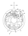
- FIG. 1 is a front view of the drum brake device.
- FIG. 2 is a rear view of the drum brake.
- FIG. 3 is a vertical cross-sectional view of the electric actuator.
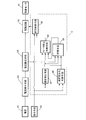
- FIG. 4 is a block diagram showing the configuration of the control unit.
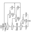
- FIG. 5 is a flowchart showing a part of the control procedure.
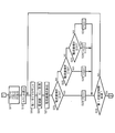
- FIG. 6 is a flowchart showing a control procedure following the control procedure of FIG.
- FIG. 7 is a flowchart showing a control procedure following the control procedure of FIG.
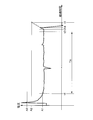
- FIG. 8 is a diagram showing an example of a change in the energizing current at the time of reversing the electric motor with the passage of time.
- FIGS. 1 to 8 An embodiment of the present invention will be described with reference to FIGS. 1 to 8 attached.
- a drum brake B is provided on a wheel of a four-wheeled vehicle, for example, the left rear wheel, and the drum brake B is fixed with a through hole 12 in the center for penetrating the axle 11 of the left rear wheel.
- the first and second brake shoes 15, 16 and the first and second brake shoes 15 and 16 arranged in the back plate 13 so as to be slidable with the back plate 13 and the inner circumference of the brake drum 14 rotating with the left rear wheel.
- a braking gap automatic adjusting means (so-called auto adjuster) 18 for automatically adjusting the gap and a return spring 19 provided between the first and second brake shoes 15 and 16 are provided.
- the first and second brake shoes 15 and 16 include the first and second webs 15a and 16a formed in a bow-shaped flat plate shape along the inner circumference of the brake drum 14, and their first and second brake shoes 15a and 16a.
- the first and second rims 15b and 16b are connected so as to be orthogonal to the outer periphery of the second webs 15a and 16a, and the first and second rims 15b and 16b attached to the outer periphery of the first and second rims 15b and 16b. It consists of a second lining 15c and 16c.
- an anchor plate 21 serving as a fulcrum during expansion and contraction of the first and second brake shoes 15 and 16 is provided at one end of the first and second webs 15a and 16a (this embodiment). Then, the lower end portion) is fixed so as to be rotatably supported. Further, the wheel cylinder 17 is operated by the output hydraulic pressure of a master cylinder (not shown) operated by a brake pedal to expand the first and second brake shoes 15 and 16 with the anchor plate 21 as a fulcrum. A pair of pistons 20 included in the wheel cylinder 17 are fixed to the back plate 13 between the other ends of the first and second brake shoes 15 and 16 so as to exert a driving force to the side. The outer end portion is arranged so as to face the other end portion (upper end portion in this embodiment) of the first and second webs 15a and 16a.
- a coil spring 22 is provided between the one ends of the first and second webs 15a and 16a to urge the one ends of the first and second webs 15a and 16a toward the anchor plate 21.
- a pair of return springs 19 for urging the first and second brake shoes 15 and 16 in the contraction direction are provided between the other ends of the first and second webs 15a and 16a.
- the braking gap automatic adjusting means 18 is provided between the first and second webs 15a and 16a of the first and second brake shoes 15 and 16, and is a contraction position regulating that can be extended by rotation of the adjusting gear 23. It has a strut 24 and a feed claw 25a that engages with the adjust gear 23, and can rotate to the second web 16a of the second brake shoe 16 of the first and second brake shoes 15 and 16. It is composed of an adjusting lever 25 that is supported and an adjusting spring 26 that rotates and urges the adjusting lever 25 to the side that rotates the adjusting gear 23 in a direction that extends the contraction position regulating strut 24.
- the contraction position regulating strut 24 regulates the contraction positions of the first and second brake shoes 15 and 16, and the first brake shoe 15 of the first and second brake shoes 15 and 16 is provided.
- a first rod 27 having a first engaging connecting portion 27a that engages with the other end of the first web 15a and a second web 16a provided with the second brake shoe 16 near the other end.
- a second rod 28 having a second engaging connecting portion 28a that engages with the first rod 27 and arranged coaxially with the first rod 27, and one end of the first rod 27 being inserted into the first rod 27 so as to be relatively movable in the axial direction.
- the two rods 28 have an adjusting bolt 29 whose other end is coaxially screwed, and the adjusting gear 23 is arranged between the first and second rods 27 and 28 to provide an outer circumference of the adjusting bolt 29. Is formed in.
- a first locking recess 30 for engaging the first engaging connecting portion 27a is provided on the side edge of the first web 15a near the other end and facing the axle 11 side, and the second web 16a is provided.
- a second locking recess 31 for engaging the second engaging connecting portion 28a is provided on the side edge facing the axle 11 side near the other end of the above.
- the adjusting lever 25 having a feed claw 25a that engages with the adjusting gear 23 is rotatably supported by the second web 16a via a support shaft 32, and is rotatably supported between the second web 16a and the adjusting lever 25. Is provided with the adjust spring 26. Moreover, the spring force of the adjust spring 26 is set to be smaller than the spring force of the return spring 19.
- the first and second linings 15c and 16c are worn when the first and second brake shoes 15 and 16 are extended by the operation of the wheel cylinder 17.
- the adjustment lever 25 is expanded by a certain value or more due to the above, the adjust lever 25 is rotated around the axis of the support shaft 32 by the spring force of the adjust spring 26, whereby the adjust gear 23 is rotated.
- the effective length of the contraction position regulating strut 24 is increased and corrected accordingly.
- the drum brake B includes a parking brake lever 34 capable of generating a parking brake force according to the operation, and the parking brake lever 34 is one of the first webs 15a of the first brake shoe 15.
- the brake drum 14 is arranged so as to overlap with each other in a front view (direction shown in FIG. 1) in a direction along the rotation axis of the brake drum 14, and extends long along the longitudinal direction of the first web 15a.
- An engaging piece 36 fixed to one end of the brake cable 37 is engaged with one end of the parking brake lever 34 (the lower end in this embodiment), and the other end of the parking brake lever 34 (this).
- the upper end portion is connected to the other end portion of the first web 15a in the first brake shoe 15 via a pin 35.
- the parking brake lever 34 When the parking brake of the vehicle is activated, the parking brake lever 34 is rotated and driven in the counterclockwise direction of FIG. 1 with the pin 35 as a fulcrum by the traction force input from the brake cable 37. Due to the rotation of the lever 34, a force in a direction in which the second lining 16c of the brake shoe 16 is pressed against the inner circumference of the brake drum 14 is applied to the second brake shoe 16 via the contraction position regulating strut 24. To work. Further, when the parking brake lever 34 is continuously rotated and driven in the counterclockwise direction of FIG. 1, the parking brake lever 34 engages with the first engaging connecting portion 27a of the contraction position regulating strut 24.
- the parking brake lever 34 operates at an operating position where the first and second linings 15c and 16c of the first and second brake shoes 15 and 16 are in pressure contact with the inner circumference of the brake drum 14. , The parking brake state can be obtained in this state.
- the first operation is performed by the spring force of the return spring 19 in a direction away from the inner circumference of the brake drum 14.
- the parking brake lever 34 returns to the non-operating position together with the second brake shoes 15 and 16, and the parking brake lever 34 is urged toward the non-operating position side.
- the brake cable 37 is towed by the power exerted by the electric actuator 38, and the electric actuator 38 has a screw shaft 39 connected to the brake cable 37 and the screw shaft 39.
- an actuator case 40 that supports the screw shaft 39 so as to be able to reciprocate in the axial direction while blocking its rotation
- an electric motor 41 that is supported by the actuator case 40 with free forward and reverse rotation
- the electric motor 41 A motion conversion mechanism 42 (see FIG. 3) that is interposed between the electric motor 41 and the screw shaft 39 and housed in the actuator case 40 while enabling the rotational motion to be converted into a linear motion of the screw shaft 39. ) And.
- the actuator case 40 of the electric actuator 38 is attached to the back plate 13 on the opposite side of the wheel cylinder 17 via the attachment member 43.
- the mounting member 43 is fixed to the actuator case 40, and the mounting member 43 is fastened to the back plate 13 with a plurality of, for example, three bolts 44.
- the brake cable 37 that is arranged outside the back plate 13 is covered with a tubular member, and in this embodiment, for example, a member formed by winding an iron wire rod into a coil shape.
- the outer cable 45 covers at least a portion of the brake cable 37 that is arranged outside the back plate 13.
- the tubular member may be a member that can receive a reaction force due to the output of the electric actuator 38, and a metal tubular member may be used instead of the outer cable 45.
- the screw shaft 39 of the electric actuator 38 is connected to the brake cable 37 via a cable joint 51, and the screw shaft 39 and the connecting portion of the brake cable 37 are connected to each other. It is covered with a protective cylinder 50 coupled to the actuator case 40, and the end of the outer cable 44 on the electric actuator 38 side is attached to the protective cylinder 50 via a guide tube 52.
- a tubular portion 13b is integrally projected from the lower portion of the back plate 13 along the vehicle front-rear direction, and the brake cable 37 covered with the outer cable 45 is formed from the tubular portion 13b to the back plate. Introduced in 13.
- a holding plate 46 sandwiching the anchor plate 21 with the back plate 13 is formed by a pair of rivets 47 together with the anchor plate 21 to form the back plate.
- a guide portion 46a which is attached to the lower part of the 13 and guides the brake cable 37 together with the outer cable 44, is integrally provided on the holding plate 46 so as to have a substantially U-shaped cross-sectional shape.
- the actuator case 40 includes a case main body 57 integrally having first and second accommodating cylinders 55 and 56, a first cover member 58 coupled to an open end of the first accommodating cylinder 55, and a first cover member 58. It is composed of a cover member 58 of 1 and a second cover member 59 coupled to the case main body 57 from the opposite side.
- the first accommodating cylinder portion 55 is formed in a bottomed cylindrical shape so that a first end wall portion 55a is provided at one end thereof, and is fitted to a central portion of the first end wall portion 55a.
- the holes 60 are formed coaxially.
- the second accommodating cylinder portion 56 is arranged on the side of the first accommodating cylinder portion 55, has one end opened, and is arranged in the intermediate portion in the longitudinal direction of the first accommodating cylinder portion 55. It is formed in a bottomed cylindrical shape so that the other end is closed by the end wall portion 56a, and a cylindrical tubular portion 56b surrounding the screw shaft 39 is integrated with the central portion of the second end wall portion 56a. It is thrust into. Further, a boot 80 is provided between the protruding end of the screw shaft 39 from the tubular portion 56b and the tubular portion 56b.
- a cylindrical first bearing portion 63a that rotatably supports the motor shaft 64 is projected from one end portion of the motor case 63 of the electric motor 41 in the axial direction, and one end portion of the motor shaft 64 is the first bearing.
- the bearing portion 63b is projected.
- one end of the motor case 63 is brought into contact with the first end wall portion 55a while fitting the first bearing portion 63a into the fitting hole 60 of the case main body 57.
- the electric motor 41 is accommodated in the first accommodating cylinder portion 55 in this way so that the other end of the motor case 63 on the side where the second bearing portion 63b is provided faces the outside. Is housed in the first storage tube portion 55.
- the first cover member 58 covers the portion of the electric motor 41 housed in the first storage cylinder portion 55 that faces the outside from the first storage cylinder portion 55, and the first storage cylinder portion 55.
- a lid portion 58a coupled to the opening end and a connector portion 58b (see FIG. 2) that projects laterally from the lid portion 58a and is arranged laterally of the first storage cylinder portion 55 are integrally provided.
- a wave washer 66 is interposed between the second bearing portion 63b and the lid portion 58a of the electric motor 41.
- the second cover member 59 is coupled to the case main body 57 so as to form a gear chamber 65 with the case main body 57, and the motion conversion mechanism 42 is housed in the gear chamber 65.
- the motion conversion mechanism 42 includes a drive gear 67 provided on the motor shaft 64 of the electric motor 41, an intermediate large-diameter gear 68 that meshes with the drive gear 67, and an intermediate small-diameter gear that rotates together with the intermediate large-diameter gear 68. It has a 69, a driven gear 70 that meshes with the intermediate small-diameter gear 69, and a nut 71 that is integrally provided with the driven gear 70.
- the intermediate large-diameter gear 68 and the intermediate small-diameter gear 69 are integrally formed, and are rotatably supported by a support shaft 72 parallel to the motor shaft 64 and the screw shaft 39. Both ends of the support shaft 72 are supported by the case main body 57 and the second cover member 59.
- the nut 71 has a radius from a large-diameter cylindrical portion 71a rotatably housed in the second accommodating cylinder portion 56 and an end portion of the large-diameter cylindrical portion 71a opposite to the second cover member 59.
- a small-diameter cylindrical portion 71c that extends inwardly extending in the direction and extends to the side opposite to the second cover member 59 and penetrates the screw shaft 39 so as to be connected to the inner peripheral edge of the inward flange 71b.
- an outward flange portion 71d that projects outward in the radial direction from the end portion of the large-diameter cylindrical portion 71a on the side of the second cover member 59.
- a female screw 67 screwed to the screw shaft 39 is engraved on the inner circumference of the small-diameter cylindrical portion 71c, and the driven gear 70 is formed on the outer circumference of the outward flange portion 71d.
- a ball bearing 74 is interposed between the small-diameter cylindrical portion 71c and the end of the second accommodating cylinder portion 56 on the second end wall portion 56a side.
- the nut 71 is formed so that the recess 75 defined by the large-diameter cylindrical portion 71a and the inward flange portion 71b of the nut 71 opens toward the protrusion 39a side.
- the recess 75 accommodates a plurality of the disc springs 76 and a disk-shaped retainer 77 that sandwiches the disc springs 76 between the inward flange 71b of the nut 71.
- the second cover member 59 of the actuator case 40 is integrally formed with a bottomed cylindrical guide cylinder portion 59a surrounding the screw shaft 39, and the inner surface of the guide cylinder portion 59a is described as described above.
- a pair of locking grooves 78 that extend along the axis of the screw shaft 39 and engage the protrusion 39a in a slidable manner are formed.
- a bearing member 79 that receives a thrust load from the nut 71 is interposed between the open end of the guide cylinder portion 59a and the nut 71, and the bearing member 79 is short that is inserted into the recess 75. It has a cylindrical portion 79a integrally.
- the screw shaft 39 has its protrusion 39a due to the forward rotation operation of the electric motor 41. Moves in a direction away from the retainer 77, but the outer peripheral portion of the retainer 72 comes into contact with the short cylindrical portion 79a of the bearing member 79 to prevent the disc spring 76 from detaching from the recess 75. NS. Further, when the electric motor 41 is reversely operated so as to loosen the brake cable 37, the screw shaft 39 moves in a direction in which the protrusion 39a approaches the retainer 77, but the brake cable 37 is on the non-operating position side.
- the electric motor 41 Since the spring is urged toward, the electric motor 41 is in a no-load state until the protrusion 39a abuts on the retainer 77, and after the protrusion 39a abuts on the retainer 77, the protrusion 39a.
- the elastic force of the disc spring 76 acts on the portion 39a via the retainer 77, and a load is applied to the electric motor 41.
- the electric power of the power supply 81 is supplied to the electric motor 41 in the electric actuator 38 via the drive circuit 82, and the operation of the electric motor 41, that is, the operation of the drive circuit 82 is a control unit. It is controlled by C.
- the control unit C is provided with an instruction means 83 for detecting that the vehicle user has performed an operation for releasing the parking brake state and outputting a signal for releasing the parking brake state, and the electric motor 41.
- the current detecting means 84 for detecting the energizing current and the voltage detecting means 85 for detecting the energizing voltage to the electric motor 41 are connected.
- the control unit C moves the parking brake lever 34, which is in the operating position in the parking brake state, to the non-operating position in response to a signal input from the instruction means 83.
- the energization control means 86 that controls the operation of the drive circuit 82 so as to start energization of the electric motor 41 to the return side, and the inclination calculation means 87 that calculates the inclination of the detected current value by the current detection means 84.
- a load is applied to the electric motor 41 after the current stabilization determining means 88 for determining whether or not the energizing current has stabilized after the start of energization of the electric motor 41 and the current stabilization determining means 88 for determining the stabilization of the energizing current.
- the storage means 89 that stores the slope of the current value calculated by the tilt calculation means 87 until just before this, and the slope of the current value stored by the storage means 89 with the electric motor 41 loaded.
- a motor stop determining means 90 that inputs a signal for stopping the operation of the electric motor 41 to the energizing control means 86 based on the inclination calculating means 87 calculating the inclination of the current value on the increasing side other than the above. include.
- step S2 After the signal for the current is input from the energization control means 86 to the drive circuit 82, the current value A (n) detected by the current detection means 84 is acquired, and in the next step S3, the flag FI1 is set to ". 1 ”is determined.
- This flag FI1 is for determining the start of the inrush current, and when it is determined in step S3 that FI1 is "0", the current value A (n) is equal to or greater than the inrush current start determination current A0 in step S4.
- step S4 When it is determined whether or not A (n) ⁇ A0, the process proceeds from step S4 to step S5, the flag FI1 is set to "1", and then the process returns to step S2 and A (n). ) ⁇ A0 is determined, the process proceeds from step S4 to step S6, the flag FI1 is set to "0", and then the process returns to step S2.
- step S7 determines whether or not the flag FI2 is "1".
- This flag FI2 is for determining the end of the inrush current, and when it is determined in step S7 that FI2 is "0", the current value A (n) is equal to or less than the inrush current end determination current A1 in step S8.
- step S8 determines whether or not A (n) ⁇ A1
- the process proceeds from step S8 to step S9, the flag FI2 is set to "1", and then the process returns to step S2 and A (n). )>
- the flag FI2 is set to "0", and then the process returns to step S2.
- steps S1 to S10 described above is performed by the current stabilization determining means 88, and as shown in FIG. 8, the reverse operation of the electric motor 41 for releasing the parking brake state is started and the inrush current is generated.
- the current after the current instability due to the rush current immediately after the start of energization has passed from the time t1 when the current value A (n) is generated and the rush current start judgment current A0 or more and then the rush current end judgment current A1 or less. It will enter a stabilized state.
- step S7 the process proceeds from step S7 to step S11, and the voltage value V (n) detected by the voltage detecting means 85 is acquired in step S11.
- step S12 it is determined whether or not the voltage value V (n) is equal to or less than the first set voltage value VA, and when V (n) ⁇ VA, the process proceeds to step S13 and the first set time TA. Is set in TA1.
- step S12 it is determined that V (n)> VA
- step S14 it is determined whether or not the voltage value V (n) is equal to or less than the second set voltage value VB.
- step S15 to set the first set time TA to TA2
- V (n)> VB the process proceeds to step S16 to set the first set time TA. Specified in TA3.
- the first set time TA is set to three values of TA1, TA2, and TA3 according to the voltage value V (n) detected by the voltage detecting means 85.
- the process proceeds to step S17 of FIG. After setting the count value to "0", the count by the first timer is executed in the next step S19, and the current value A (n) detected by the current detecting means 84 is acquired in the next step S20.
- step S21 following step S20 the slope of the current value is calculated by the slope calculation means 87.
- the slope calculation means 87 has the current value A (n) acquired this time and the slope calculation means.
- the difference from the current value A (n-1) acquired in the previous calculation before the calculation cycle in 87 is calculated as a value representing the slope of the current value.
- step S22 it is determined whether or not the slope of the current value is equal to or less than the first predetermined value SA, and when the slope of the current value ⁇ SA, the process proceeds to step S23 and the flag FS1 is set to "1". After determining, the process proceeds to step S24. Further, when it is determined in step S22 that the slope of the current value> SA, it is determined in step S25 whether or not the slope of the current value is greater than the first predetermined value SA and equal to or less than the second predetermined value SB. When it is determined in step S25 that the slope of the current value is ⁇ SB, the process proceeds to step S26 to set the flag FS2 to “1” and then to step S24.
- step S25 To step S27, it is determined whether or not the slope of the current value is equal to or less than the third predetermined value SC, which is larger than the second predetermined value SB.
- the flag FS3 is set to “1” in step S28 and then the process proceeds to step S24. After determining "1", the process proceeds to step S24.
- step S24 it is determined whether or not the time measurement by the first timer has reached the first set time TA, and if the time measurement by the first timer has not reached the first set time TA, the process returns to step S19 and the first set time TA is reached. When it is determined that the value has been reached, the process proceeds to step S30 of FIG.
- steps S17 to S29 described above is performed by the storage means 89, and as shown in FIG. 8, immediately before the time t3 when the electric motor 41 is loaded from the time t1 when the current destabilization state due to the inrush current ends.
- the slope of the current value calculated by the tilt calculation means 87 is set by the flags FS1, FS2, FS3, according to the magnitude of the tilt.
- FS4 as "1"
- the gradient of the current value generated between the time when the energizing current stabilizes and the time when the first set time TA elapses is set according to the magnitude of the flags FS1, FS2, FS3.
- the storage means 89 stores the FS4 while attaching the FS4.
- the slope of the current value used for determining the operation stop of the electric motor 41 by the motor stop determination means 90 is larger than the first predetermined value SA, and is the third. It is set in a range that is equal to or less than the predetermined value SC of.
- step S30 of FIG. 7 the current value A (n) detected by the current detecting means 84 is acquired, and in the subsequent step S31, the slope of the current value is calculated by the slope calculating means 87.
- the tilt calculation means 87 sets the difference from the current value A (n-1) acquired in the previous calculation before the calculation cycle in the tilt calculation means 87 as the slope of the current value. Calculated as a representative value.
- step S32 it is determined whether or not the slope of the current value is equal to or less than the first predetermined value SA, and when the slope of the current value is equal to or less than the first predetermined value SA, the count value by the second timer is set in step S33. After setting “0”, the process proceeds to step S39, and when the slope of the current value exceeds the first predetermined value SA, the process proceeds from step S32 to step S34. In this step S34, it is determined whether or not the slope of the current value is equal to or less than the second predetermined value SB and the flag FS2 is “0”, and the slope of the current value is equal to or less than the second predetermined value SB.
- step S35 When the flag FS2 is "0", the count by the second timer is executed in step S35, and then the process proceeds to step S39.
- Step S34 When the slope of the current value exceeds the second predetermined value SB or the flag FS2 is "1". , Step S34 to step S36.
- step S36 it is determined whether or not the slope of the current value is equal to or less than the third predetermined value SC and the flag FS3 is “0”, and the slope of the current value is equal to or less than the third predetermined value SC and the flag is flagged.
- the FS3 is "0”
- the count by the second timer is executed in step S35, and when the slope of the current value exceeds the third predetermined value SC or the flag FS3 is "1", steps S36 to S37 Proceed to.
- the current value gradient other than the current value gradient stored by the storage means 89 is generated by the processing of steps S32 to S39, that is, the first predetermined value SA is exceeded and the second predetermined value SB or less is formed.
- the slope of the current value of is generated after the lapse of the first set time TA, or when the slope of the current value exceeding the second predetermined value SB and equal to or less than the third predetermined value SC is the first set time TA.
- the count by the second timer is executed, and when the inclination of the current value equal to the inclination of the current value stored in the storage means 89 occurs, and the inclination of the current value is equal to or less than the first predetermined value SA.
- the count value by the second timer is set to "0".
- step S33 After executing the count by the second timer in step S33, the process proceeds to step S39, and in this step S39, it is determined whether or not the elapsed time due to the count of the second timer exceeds the second set time.
- This second set time is set as the time required for determining the slope of the current value.
- step S39 When it is determined in step S39 that the second set time has elapsed, the process proceeds to step S40 and a signal for stopping the electric motor 41 is input to the energization control means 86.
- step S39 When it is determined in step S39 that the second set time has not elapsed, the process proceeds from step S39 to step S41, and it is determined whether or not the current value A (n) is equal to or greater than the set current value A2.
- n) ⁇ A2 the process proceeds from step S41 to step S40, and when A (n) ⁇ A2, the process returns from step S41 to step S39.
- steps S30 to S41 described above is performed by the motor stop determination means 90, and as shown in FIG. 8, the current stored by the storage means 89 after the time t3 when the load starts to be applied to the electric motor 41.
- the motor stop determination means 90 inputs a signal for stopping the operation of the electric motor 41 to the energization control means 86 at that time t4.
- the motor stop determining means 90 sends a signal for stopping the operation of the electric motor 41 at the time t5 when the detected current value of the current detecting means 84 becomes the set current value A2 or more. Enter in.
- the control unit C that controls the operation of the electric motor 41 included in the electric actuator 38 includes the inclination calculation means 87 that calculates the inclination of the detected current value by the current detection means 84, and parking. Based on the current value detected by the current detecting means 84, it is determined that the energizing current has stabilized after the energization of the electric motor 41 to the side where the parking brake lever 34 in the operating position is returned to the non-operating position in the braking state is started.
- the tilt calculation means 87 calculates the slope of the current value on the increasing side other than the slope of the current value stored in the storage means 89 and the storage means 89 after the lapse of the first set time TA. Since the motor stop determination means 90 for stopping the operation of the electric motor 41 based on the above is included, the electric motor 41 is loaded after the no-load current state is completed, and the electric motor 41 is in a no-load current state. The operation of the electric motor 41 was stopped in response to detecting the inclination on the increasing side of the current value other than the inclination of the current value caused by the noise, which was caused by the noise caused by various electric factors and mechanical factors. By eliminating the inclination of the current value, the operation of the electric motor 41 can be stopped quickly and accurately after the lapse of the no-load current state.
- the motor stop determining means 90 is in a state where non-detection of the inclination of the current value on the increasing side other than the inclination of the current value stored in the storage means 89 continues after the lapse of the first set time TA. Since the operation stop of the electric motor 41 is determined based on the detected current value of the detection means 84, even if the operation stop of the electric motor 41 cannot be determined due to the inclination of the current value, the operation of the electric motor 41 is surely determined by the current value. Can be stopped.
Landscapes
- Engineering & Computer Science (AREA)
- Transportation (AREA)
- Mechanical Engineering (AREA)
- Power Engineering (AREA)
- Regulating Braking Force (AREA)
- Stopping Of Electric Motors (AREA)
- Braking Systems And Boosters (AREA)
Abstract
車両用電動パーキングブレーキ装置において、電動モータ(41)の作動を制御する制御ユニット(C)は、電流検出手段(84)による検出電流値の傾きを演算する傾き演算手段(87)と、パーキングブレーキレバー(34)を非作動位置に戻す側への電動モータへの通電開始後に通電電流が安定したことを判断する電流安定化判断手段(88)と、通電電流が安定化した後の設定時間内の電流値の傾きを記憶する記憶手段(89)と、設定時間の経過後に記憶手段で記憶された電流値の傾き以外の増大側の電流値の傾きを傾き演算手段が演算するのに基づいて電動モータの作動を停止するモータ停止判断手段(90)とを含む。これにより電動モータを有する電動アクチュエータが、パーキングブレーキレバーを非作動位置に動かしてパーキングブレーキ状態を解除する際に、無負荷電流状態経過後に早くかつ正確に電動モータの作動を停止する。
Description
本発明は、パーキングブレーキ状態を得る作動位置ならびにパーキングブレーキ状態を解除する非作動位置間での回動を可能とするとともに前記非作動位置側に向けて弾発付勢されるパーキングブレーキレバーと;当該パーキングブレーキレバーを前記非作動位置から前記作動位置に動かす動力を発揮する正転状態ならびに前記パーキングブレーキレバーを前記作動位置から前記非作動位置側に戻す際の逆転状態を切替え可能として前記パーキングブレーキレバーに連結される電動モータを有するとともに前記電動モータの逆転時に当該電動モータの負荷が無負荷となる状態を経過した後に前記電動モータに負荷を与えることを可能とした電動アクチュエータと;前記電動モータの作動を制御する制御ユニットと;前記電動モータへの通電電流を検出する電流検出手段と;を備える車両用電動パーキングブレーキ装置に関する。
電動アクチュエータの作動によってパーキングブレーキレバーを作動位置に動かしてパーキングブレーキ状態を得るとともに、パーキングブレーキレバーを非作動位置に動かすように電動アクチュエータが作動するのに応じてパーキングブレーキ力を解放するようにした車両用電動パーキングブレーキ装置が、特許文献1で知られている。
ところで、車両用電動パーキングブレーキ装置においてパーキングブレーキ解除時には、電動アクチュエータの電動モータにかかる負荷が小さくなって無負荷電流と区別できなくなり、電動アクチュエータを構成する複数の部材で戻し過ぎが生じてロック状態に陥る可能性がある。このため上記特許文献1で開示されたものでは、電動アクチュエータの一部を構成する直動部材にばねによる負荷を与えることで、電動モータへの通電電流の増大側の傾きを検出し、その傾きが予め設定した所定値以上となるのに応じて前記戻し過ぎが生じるのを防止するようにしている。しかるに電流値の傾きは、様々な電気的要因や機械的要因(たとえば外部電圧変動やモータ内部構造等)によるノイズによっても変動するものであり、上記特許文献1開示のものでは、そのような変動に起因して電動モータの作動停止が誤って早められてしまう可能性がある。
本発明は、かかる事情に鑑みてなされたものであり、パーキングブレーキ状態を解除する際に無負荷電流状態経過後に早くかつ正確に電動モータの作動を停止し得るようにした車両用電動パーキングブレーキ装置を提供することを目的とする。
上記目的を達成するために、本発明は、パーキングブレーキ状態を得る作動位置ならびにパーキングブレーキ状態を解除する非作動位置間での回動を可能とするとともに前記非作動位置側に向けて弾発付勢されるパーキングブレーキレバーと;当該パーキングブレーキレバーを前記非作動位置から前記作動位置に動かす動力を発揮する正転状態ならびに前記パーキングブレーキレバーを前記作動位置から前記非作動位置側に戻す際の逆転状態を切替え可能として前記パーキングブレーキレバーに連結される電動モータを有するとともに前記電動モータの逆転時に当該電動モータの負荷が無負荷となる状態を経過した後に前記電動モータに負荷を与えることを可能とした電動アクチュエータと;前記電動モータの作動を制御する制御ユニットと;前記電動モータへの通電電流を検出する電流検出手段と;を備える車両用電動パーキングブレーキ装置において、前記制御ユニットは、前記制御ユニットは、前記電流検出手段による検出電流値の傾きを演算する傾き演算手段と、前記パーキングブレーキ状態で前記作動位置に在る前記パーキングブレーキレバーを前記非作動位置に戻す側への前記電動モータへの通電開始後に通電電流が安定したことを前記電流検出手段による検出電流値に基づいて判断する電流安定化判断手段と、通電電流が安定化したことを前記電流安定化判断手段が判断した後の設定時間内に前記傾き演算手段によって演算される電流値の傾きを記憶する記憶手段と、前記設定時間の経過後に前記記憶手段で記憶された電流値の傾き以外の増大側の電流値の傾きを前記傾き演算手段が演算するのに基づいて前記電動モータの作動を停止するようにしたモータ停止判断手段とを含むことを第1の特徴とする。
また本発明は、第1の特徴の構成に加えて、前記モータ停止判断手段は、前記設定時間の経過後に前記記憶手段で記憶された電流値の傾き以外の増大側の電流値の傾きの非検出が持続する状態では前記電流検出手段の検出電流値に基づいて前記電動モータの作動停止を判断することを第2の特徴とする。
本発明の第1の特徴によれば、無負荷電流状態が終了した後に電動モータに負荷がかかっている状態で、無負荷電流状態でのノイズによって生じた電流値の傾き以外の電流値の増大側の傾きを検出するのに応じて電動モータの作動を停止するので、様々な電気的要因や機械的要因によるノイズに起因した電流値の傾きを排除して、無負荷電流状態経過後に早くかつ正確に電動モータの作動を停止することができる。
また本発明の第2の特徴によれば、電流値の傾きによって電動モータの作動停止が判断できない場合でも、電流値によって電動モータの作動を確実に停止することができる。
34・・・パーキングブレーキレバー
38・・・電動アクチュエータ
41・・・電動モータ
84・・・電流検出手段
87・・・傾き演算手段
88・・・電流安定化判断手段
89・・・記憶手段
90・・・モータ停止判断手段
C・・・制御ユニット
38・・・電動アクチュエータ
41・・・電動モータ
84・・・電流検出手段
87・・・傾き演算手段
88・・・電流安定化判断手段
89・・・記憶手段
90・・・モータ停止判断手段
C・・・制御ユニット
本発明の実施の形態について、添付の図1~図8を参照しながら説明する。
先ず図1において、四輪車両の車輪たとえば左後輪にドラムブレーキBが設けられており、このドラムブレーキBは、前記左後輪の車軸11を貫通させる貫通孔12を中央部に有する固定のバックプレート13と、前記左後輪とともに回転するブレーキドラム14の内周に摺接することを可能として前記バックプレート13内に配置される第1および第2のブレーキシュー15,16と、第1および第2のブレーキシュー15,16が拡張作動する力を発揮するようにして前記バックプレート13に固定されるホイールシリンダ17と、第1および第2のブレーキシュー15,16および前記ブレーキドラム14間の間隙を自動的に調整する制動間隙自動調整手段(所謂オートアジャスタ)18と、第1および第2のブレーキシュー15,16間に設けられるリターンスプリング19とを備える。
第1および第2のブレーキシュー15,16は、前記ブレーキドラム14の内周に沿うようにして弓形の平板状に形成される第1および第2のウエブ15a,16aと、それらの第1および第2のウエブ15a,16aの外周に直交するように連設される第1および第2のリム15b,16bと、第1および第2のリム15b,16bの外周に貼着される第1および第2のライニング15c,16cとから成る。
前記バックプレート13には、第1および第2のブレーキシュー15,16の拡張、収縮時の支点となるアンカープレート21が、第1および第2のウエブ15a,16aの一端部(この実施の形態では下端部)を回動可能に支持するようにして固設される。また前記ホイールシリンダ17は、ブレーキペダルで操作されるマスタシリンダ(図示せず)の出力液圧によって作動して、前記アンカープレート21を支点として第1および第2のブレーキシュー15,16を拡張する側に駆動する力を発揮するようにして、第1および第2のブレーキシュー15,16の他端部間で前記バックプレート13に固定されており、このホイールシリンダ17が備える一対のピストン20の外端部は、第1および第2のウエブ15a,16aの他端部(この実施の形態では上端部)に対向するように配置される。
第1および第2のウエブ15a,16aの前記一端部間には、それらの第1および第2のウエブ15a,16aの前記一端部を前記アンカープレート21側に付勢するコイルスプリング22が設けられ、第1および第2のウエブ15a,16aの他端部間には、第1および第2のブレーキシュー15,16を収縮方向に付勢する一対の前記リターンスプリング19が設けられる。
前記制動間隙自動調整手段18は、第1および第2のブレーキシュー15,16が有する第1および第2のウエブ15a,16a間に設けられるとともにアジャストギヤ23の回動によって伸長し得る収縮位置規制ストラット24と、前記アジャストギヤ23に係合する送り爪25aを有して第1および第2のブレーキシュー15,16のうち第2のブレーキシュー16の前記第2のウエブ16aに回動可能に支持されるアジャストレバー25と、前記収縮位置規制ストラット24を伸長させる方向に前記アジャストギヤ23を回動させる側に前記アジャストレバー25を回動付勢するアジャストスプリング26とで構成される。
前記収縮位置規制ストラット24は、第1および第2のブレーキシュー15,16の収縮位置を規制するものであり、第1および第2のブレーキシュー15,16のうち第1のブレーキシュー15が備える前記第1のウエブ15aの前記他端部寄りに係合する第1係合連結部27aを有する第1ロッド27と、第2のブレーキシュー16が備える第2のウエブ16aの前記他端部寄りに係合する第2係合連結部28aを有して第1ロッド27と同軸に配置される第2ロッド28と、第1ロッド27に一端部が軸方向相対移動可能に挿入されるとともに第2ロッド28に他端部が同軸に螺合されるアジャストボルト29とを有しており、前記アジャストギヤ23は、第1および第2ロッド27,28間に配置されて前記アジャストボルト29の外周に形成される。
第1のウエブ15aの前記他端部寄りの前記車軸11側に臨む側縁には、第1係合連結部27aを係合させる第1係止凹部30が設けられ、また第2のウエブ16aの前記他端部寄りの前記車軸11側に臨む側縁には、第2係合連結部28aを係合させる第2係止凹部31が設けられる。
前記アジャストギヤ23に係合する送り爪25aを有するアジャストレバー25は、前記第2のウエブ16aに支軸32を介して回動可能に支持され、前記第2のウエブ16aおよび前記アジャストレバー25間に前記アジャストスプリング26が設けられる。しかも前記アジャストスプリング26のばね力は、前記リターンスプリング19のばね力よりも小さく設定される。
このような制動間隙自動調整手段18によれば、第1および第2のブレーキシュー15,16が前記ホイールシリンダ17の作動によって拡張作動する際に前記第1および第2のライニング15c,16cの摩耗に起因して一定値以上拡張した場合には、前記アジャストスプリング26のばね力によって前記アジャストレバー25が前記支軸32の軸線まわりに回動し、それによって前記アジャストギヤ23が回動するのに応じて前記収縮位置規制ストラット24の有効長さが増加補正される。
ところで、このドラムブレーキBは、作動に応じてパーキングブレーキ力を発生させ得るパーキングブレーキレバー34を備えており、このパーキングブレーキレバー34は、第1のブレーキシュー15における前記第1のウエブ15aの一部に、前記ブレーキドラム14の回転軸線に沿う方向での正面視(図1で示す方向)で重なるように配置され、前記第1のウエブ15aの長手方向に沿って長く延びる。
前記パーキングブレーキレバー34の一端部(この実施の形態では下端部)には、ブレーキケーブル37の一端部に固定された係合駒36が係合され、前記パーキングブレーキレバー34の他端部(この実施の形態では上端部)は、第1のブレーキシュー15における前記第1のウエブ15aの他端部にピン35を介して連結される。
車両のパーキングブレーキ作動時には、前記ブレーキケーブル37から入力される牽引力により、前記パーキングブレーキレバー34が前記ピン35を支点として図1の反時計方向に回動、駆動されるものであり、このパーキングブレーキレバー34の回動によって、第2のブレーキシュー16に、当該ブレーキシュー16が有する前記第2のライニング16cを前記ブレーキドラム14の内周に圧接させる方向の力が前記収縮位置規制ストラット24を介して作用する。さらに前記パーキングブレーキレバー34が図1の反時計方向に続けて回動、駆動されると、前記パーキングブレーキレバー34が前記収縮位置規制ストラット24の第1係合連結部27aとの係合部を支点として回動し、今度は、前記ピン35を介して第1のブレーキシュー15が拡張作動し、第1のブレーキシュー15の前記第1のライニング15cが前記ブレーキドラム14の内周に圧接することになる。すなわち前記パーキングブレーキレバー34は、第1および第2のブレーキシュー15,16の前記第1および第2のライニング15c,16cが前記ブレーキドラム14の内周に圧接するようにした作動位置に作動し、この状態でパーキングブレーキ状態が得られることになる。
また前記ブレーキケーブル37を緩めることで前記パーキングブレーキレバー34に対する回動駆動力の付与を停止したときには、前記ブレーキドラム14の内周から離反する方向に前記リターンスプリング19のばね力によって作動する第1および第2のブレーキシュー15,16とともに前記パーキングブレーキレバー34は非作動位置に戻ることになり、前記パーキングブレーキレバー34は非作動位置側に向けて付勢されている。
図2を併せて参照して、前記ブレーキケーブル37は、電動アクチュエータ38が発揮する動力で牽引されるものであり、この電動アクチュエータ38は、前記ブレーキケーブル37に連結されるねじ軸39と、当該ねじ軸39をその回転を阻止しつつ軸線方向の往復運動を可能として支持するアクチュエータケース40と、正逆回転を自在として前記アクチュエータケース40に支持される電動モータ41と、その電動モータ41で発生する回転運動を前記ねじ軸39の直線運動に変換することを可能としつつ前記電動モータ41および前記ねじ軸39間に介設されて前記アクチュエータケース40に収容される運動変換機構42(図3参照)とを備える。
この電動アクチュエータ38の前記アクチュエータケース40は、前記ホイールシリンダ17とは反対側で前記バックプレート13に取付け部材43を介して取付けられる。前記取付け部材43は、前記アクチュエータケース40に固着されており、この取付け部材43が複数個たとえば3個のボルト44で前記バックプレート13に締結される。
また前記ブレーキケーブル37のうち少なくとも前記バックプレート13の外部に配索される部分は筒状部材で覆われており、この実施の形態では、たとえば鉄製の線材をコイル状に巻回して成る状部材であるアウターケーブル45で前記ブレーキケーブル37のうち少なくとも前記バックプレート13の外部に配索される部分が覆われる。また前記筒状部材は、前記電動アクチュエータ38の出力による反力を受けられる部材であればよく、前記アウターケーブル45に代えて、金属製の筒状部材を用いるようにしてもよい。
図3を併せて参照して、前記電動アクチュエータ38の前記ねじ軸39は、ケーブルジョイント51を介して前記ブレーキケーブル37に連結されており、そのねじ軸39および前記ブレーキケーブル37の連結部は、前記アクチュエータケース40に結合される保護筒50で覆われており、前記アウターケーブル44の前記電動アクチュエータ38側の端部は、ガイドチューブ52を介して前記保護筒50に取付けられる。
前記バックプレート13の下部の車両前後方向に沿う前部には筒部13bが一体に突設されており、前記アウターケーブル45で覆われた前記ブレーキケーブル37は、前記筒部13bから前記バックプレート13内に導入される。
また前記第1および第2のウエブ15a,16aの一端部間で、前記アンカープレート21を前記バックプレート13との間に挟む押さえ板46が、前記アンカープレート21とともに一対のリベット47によって前記バックプレート13の下部に取付けられ、前記押さえ板46に、前記アウターケーブル44とともに前記ブレーキケーブル37をガイドするガイド部46aが、略U字状の横断面形状を有するようにして一体に設けられる。
前記アクチュエータケース40は、第1および第2の収容筒部55,56を一体に有するケース主体57と、第1の収容筒部55の開口端に結合される第1のカバー部材58と、第1のカバー部材58と反対側から前記ケース主体57に結合される第2のカバー部材59とで構成される。
前記第1の収容筒部55は、一端部に第1の端壁部55aが設けられるようにして有底円筒状に形成され、前記第1の端壁部55aの中央部には、嵌合孔60が同軸に形成される。第2の収容筒部56は、前記第1の収容筒部55の側方に配置され、一端部を開放するとともに前記第1の収容筒部55の長手方向中間部に配置される第2の端壁部56aで他端部が閉じられるようにして有底円筒状に形成され、第2の端壁部56aの中央部には、前記ねじ軸39を囲繞する円筒状の筒部56bが一体に突設される。また前記筒部56bからの前記ねじ軸39の突出端部および前記筒部56b間にはブーツ80が設けられる。
前記電動モータ41のモータケース63の軸方向一端部には、モータ軸64を回転自在に支持する円筒状の第1軸受部63aが突設され、前記モータ軸64の一端部は前記第1軸受部63aを貫通して前記モータケース63の一端部から突出され、前記モータケース63の軸方向他端部には前記モータ軸64の他端部を回転自在に支持する有底円筒状の第2軸受部63bが突設される。
この電動モータ41は、前記第1軸受部63aを前記ケース主体57の前記嵌合孔60に嵌合するようにしつつ前記モータケース63の一端部を前記第1の端壁部55aに当接させるようにして第1の収容筒部55に収容されるものであり、前記第2軸受部63bが設けられる側の前記モータケース63の他端部を外部に臨ませるようにして、前記電動モータ41が第1の収容筒部55に収容される。
前記第1のカバー部材58は、前記第1の収容筒部55に収容される前記電動モータ41のうち第1の収容筒部55から外部に臨む部分を覆って第1の収容筒部55の開口端に結合される蓋部58aと、当該蓋部58aから側方に張り出すとともに前記第1の収容筒部55の側方に配置されるコネクタ部58b(図2参照)とを一体に有し、前記電動モータ41の前記第2軸受部63bおよび前記蓋部58a間にはウエーブワッシャ66が介設される。第2のカバー部材59は、前記ケース主体57との間にギヤ室65を形成するようにして前記ケース主体57に結合され、このギヤ室65に前記運動変換機構42が収容される。
前記運動変換機構42は、前記電動モータ41の前記モータ軸64に設けられる駆動ギヤ67と、その駆動ギヤ67に噛合する中間大径ギヤ68と、その中間大径ギヤ68とともに回転する中間小径ギヤ69と、当該中間小径ギヤ69に噛合する被動ギヤ70と、当該被動ギヤ70に一体に設けられるナット71とを有する。
前記中間大径ギヤ68および前記中間小径ギヤ69は一体に形成されており、前記モータ軸64および前記ねじ軸39と平行な支軸72で回転自在に支持される。また前記支軸72の両端部は、前記ケース主体57および前記第2のカバー部材59で支持される。
前記ナット71は、前記第2の収容筒部56内に回転自在に収容される大径円筒部71aと、大径円筒部71aの前記第2のカバー部材59とは反対側の端部から半径方向内方に張り出す内向き鍔部71bと、この内向き鍔部71bの内周縁に連なって前記第2のカバー部材59とは反対側に延びるとともに前記ねじ軸39を貫通させる小径円筒部71cと、前記大径円筒部71aの前記第2のカバー部材59側の端部から半径方向外方に張り出す外向き鍔部71dとを一体に有するように形成される。前記小径円筒部71cの内周に前記ねじ軸39に螺合する雌ねじ67が刻設され、前記外向き鍔部71dの外周に前記被動ギヤ70が形成される。また前記小径円筒部71cと、前記第2の収容筒部56の前記第2の端壁部56a側の端部との間にはボールベアリング74が介装される。
前記ブレーキケーブル37とは反対側で前記ねじ軸39の端部には、当該ねじ軸39の一直径線に沿う両側に向かって突出する突部39aが設けられる。一方、前記ナット71には、当該ナット71の前記大径円筒部71aおよび前記内向き鍔部71bで規定される凹部75が、前記突部39a側に向かって開放するようにして形成される。
ところで前記ねじ軸39は、前記パーキングブレーキレバー34を作動位置側に駆動すべく前記ブレーキケーブル37を牽引する際には前記突部39aが前記ナット71から離反する側に移動し、前記パーキングブレーキレバー34を前記作動位置から前記非作動位置側に戻すべく前記ブレーキケーブル37を緩める際には前記突部39aが前記ナット71に近接する側に移動するものであり、前記ブレーキケーブル37を緩める方向に前記ねじ軸39が移動する際に前記突部39aおよび前記ナット71間に介在して前記突部39aを前記ナット71から離反させる側に付勢する弾発力を発揮する複数個の皿ばね76が、前記凹部75に収容される。
前記凹部75には、複数個の前記皿ばね76と、それらの皿ばね76を前記ナット71の前記内向き鍔部71bとの間に挟む円板状のリテーナ77とが収容される。
前記アクチュエータケース40の前記第2のカバー部材59には、前記ねじ軸39を囲繞する有底円筒状のガイド筒部59aが一体に形成されており、このガイド筒部59aの内面には、前記ねじ軸39の軸線に沿う方向に延びて前記突部39aをスライド可能に係合させる一対の係止溝78が形成される。
前記ガイド筒部59aの開口端部および前記ナット71間には、ナット71からのスラスト荷重を受ける軸受部材79が介装されており、この軸受部材79は、前記凹部75内に突入される短円筒部79aを一体に有する。
ここで前記パーキングブレーキレバー34を前記非作動位置から前記作動位置側に駆動すべく前記ブレーキケーブル37を牽引する際には、前記電動モータ41の正転作動によって前記ねじ軸39はその突部39aが前記リテーナ77から離反する方向に移動するが、前記リテーナ72の外周部が、前記軸受部材79における前記短円筒部79aに接触することで前記皿ばね76の前記凹部75からの離脱が阻止される。また前記ブレーキケーブル37を緩めるように前記電動モータ41を逆転作動させたときには前記突部39aが前記リテーナ77に近接する方向に前記ねじ軸39が移動するが、前記ブレーキケーブル37が非作動位置側に向けてばね付勢されているので、前記突部39aが前記リテーナ77に当接するまでは前記電動モータ41は無負荷状態となり、前記突部39aが前記リテーナ77に当接した後には当該突部39aに前記リテーナ77を介して前記皿ばね76の弾性力が作用し、前記電動モータ41に負荷がかかることになる。
図4において、前記電動アクチュエータ38における前記電動モータ41には、電源81の電力が駆動回路82を介して供給されるものであり、前記電動モータ41の作動すなわち前記駆動回路82の作動は制御ユニットCで制御される。この制御ユニットCには、車両ユーザがパーキングブレーキ状態を解除するための操作を行なったことを検出してパーキングブレーキ状態を解除するための信号を出力する指示手段83と、前記電動モータ41への通電電流を検出する電流検出手段84と、前記電動モータ41への通電電圧を検出する電圧検出手段85とが接続される。
前記制御ユニットCは、そのパーキングブレーキ状態解除に関連する部分として、前記指示手段83からの信号入力に応じて前記パーキングブレーキ状態で前記作動位置に在る前記パーキングブレーキレバー34を前記非作動位置に戻す側への前記電動モータ41への通電を開始するように前記駆動回路82の作動を制御する通電制御手段86と、前記電流検出手段84による検出電流値の傾きを演算する傾き演算手段87と、前記電動モータ41への通電開始後に通電電流が安定したかどうかを判断する電流安定化判断手段88と、当該電流安定化判断手段88による通電電流の安定化判断後に前記電動モータ41に負荷がかかる直前までの間で前記傾き演算手段87によって演算される電流値の傾きを記憶する記憶手段89と、前記電動モータ41に負荷がかかった状態で前記記憶手段89で記憶された電流値の傾き以外の増大側の電流値の傾きを前記傾き演算手段87が演算するのに基づいて前記電動モータ41の作動を停止するための信号を前記通電制御手段86に入力するモータ停止判断手段90とを含む。
パーキングブレーキ状態を解除する際に、前記制御ユニットCは図5~図7で示す手順に従って前記電動モータ41の作動を制御するものであり、図5のステップS1で電動モータ41の逆転を開始するための信号を前記通電制御手段86から前記駆動回路82に入力した後のステップS2では、前記電流検出手段84で検出した電流値A(n)を取得し、次のステップS3ではフラグFI1が「1」であるか否かを判断する。このフラグFI1は、突入電流の開始を判定するためのものであり、ステップS3でFI1が「0」であると判断したときには、ステップS4で電流値A(n)が突入電流開始判定電流A0以上となるか否かを判定し、A(n)≧A0であると判定したときには、ステップS4からステップS5に進んでフラグFI1を「1」に設定した後、ステップS2に戻り、またA(n)<A0であると判定したときには、ステップS4からステップS6に進んでフラグFI1を「0」に設定した後、ステップS2に戻る。
ステップS3でFI1=1であることを確認したときには、ステップS7に進んでフラグFI2が「1」であるか否かを判断する。このフラグFI2は、突入電流の終了を判定するためのものであり、ステップS7でFI2が「0」であると判断したときには、ステップS8で電流値A(n)が突入電流終了判定電流A1以下となるか否かを判定し、A(n)≦A1であると判定したときには、ステップS8からステップS9に進んでフラグFI2を「1」に設定した後、ステップS2に戻り、またA(n)>A1であると判定したときには、ステップS8からステップS10に進んでフラグFI2を「0」に設定した後、ステップS2に戻ることになる。
上述のステップS1~ステップS10の処理は電流安定化判断手段88によるものであり、図8で示すように、パーキングブレーキ状態を解除するための前記電動モータ41の逆転作動を開始して突入電流が生じて電流値A(n)が突入電流開始判定電流A0以上となった後に突入電流終了判定電流A1以下となった時刻t1から通電開始直後の突入電流による電流不安定状態を経過した後の電流安定化状態に入ることになる。
上記ステップS7でフラグFI2が「1」となったことを確認したときには、ステップS7からステップS11に進み、前記電圧検出手段85で検出した電圧値V(n)をステップS11で取得する。次のステップS12では、電圧値V(n)が第1設定電圧値VA以下であるか否かを判定し、V(n)≦VAであったときにはステップS13に進んで第1の設定時間TAをTA1に定める。またステップS12でV(n)>VAであると判定したときには、ステップS12からステップS14に進み、このステップS14では電圧値V(n)が第2設定電圧値VB以下であるか否かを判定し、V(n)≦VBであったときにはステップS15に進んで第1の設定時間TAをTA2に定め、V(n)>VBであったときにはステップS16に進んで第1の設定時間TAをTA3に定める。
すなわちステップS11~S16は前記電圧検出手段85で検出した電圧値V(n)に応じて第1の設定時間TAをTA1,TA2,TA3の値の3つの値に定めることになる。上述のステップS13,S15,S16の処理が終了した後は、図6のステップS17に進み、このステップS17では、フラグFS1,FS2,FS3,FS4をそれぞれ「0」と定め、次のステップS18でカウント値を「0」に定めた後、次のステップS19で第1タイマによるカウントを実行し、さらに次のステップS20で前記電流検出手段84で検出した電流値A(n)を取得する。
ステップS20に続くステップS21では、前記傾き演算手段87によって電流値の傾きを算出するが、この実施の形態で前記傾き演算手段87は、今回取得した電流値A(n)と、前記傾き演算手段87における演算周期前の前回の演算で取得した電流値A(n-1)との差を、電流値の傾きを代表する値として算出する。
ステップS21に続くステップS22では、電流値の傾きが第1の所定値SA以下であるか否かを判断し、電流値の傾き≦SAであったときにはステップS23に進んでフラグFS1を「1」と定めた後、ステップS24に進む。またステップS22で電流値の傾き>SAであると判断したときにはステップS25で電流値の傾きが前記第1の所定値SAよりも大きな第2の所定値SB以下であるか否かを判断する。このステップS25で電流値の傾き≦SBであると判断したときにはステップS26に進んでフラグFS2を「1」と定めた後にステップS24に進み、電流値の傾き>SBであると判断したときにはステップS25からステップS27に進んで電流値の傾きが前記第2の所定値SBよりも大きな第3の所定値SC以下であるか否かを判断する。このステップS27で電流値の傾き≦SCであると判断したときにはステップS28でフラグFS3を「1」に定めた後にステップS24に進み、電流値の傾き>SCだったときにはステップS29でフラグFS4を「1」に定めた後にステップS24に進む。
ステップS24では、第1タイマによる時間計測が第1の設定時間TAに達したか否かを判断し、第1の設定時間TAに達していなかったときにはステップS19に戻り、第1の設定時間TAに達したと判断したときには、図7のステップS30に進む。
上述のステップS17~S29の処理は記憶手段89によるものであり、図8で示すように、突入電流による電流不安定化状態が終了した時刻t1から前記電動モータ41に負荷がかかる時刻t3の直前と想定される時刻t2までの電圧によって定まる第1の設定時間TA内に、前記傾き演算手段87によって演算される電流値の傾きを、その傾きの大きさに応じたフラグFS1,FS2,FS3,FS4を「1」と定めることにより、通電電流が安定してから第1の設定時間TAが経過するまでの間に生じた電流値の傾きをその大きさに応じたフラグFS1,FS2,FS3,FS4を付しながら前記記憶手段89が記憶することになる。
しかも前記記憶手段89によって記憶された電流値の傾きのうち前記モータ停止判断手段90による電動モータ41の作動停止判断に用いられる電流値の傾きは、第1の所定値SAよりも大きく、第3の所定値SC以下である範囲に設定されている。
図7のステップS30では、前記電流検出手段84で検出した電流値A(n)を取得し、その後のステップS31において前記傾き演算手段87によって電流値の傾きを算出するが、この実施の形態では、上述のステップS21と同様に、前記傾き演算手段87は当該傾き演算手段87における前記演算周期前の前回の演算で取得した電流値A(n-1)との差を、電流値の傾きを代表する値として算出する。
ステップS32では、電流値の傾きが第1の所定値SA以下であるか否かを判断し、電流値の傾きが第1の所定値SA以下であるときにはステップS33で第2タイマによるカウント値を「0」とした後にステップS39に進み、電流値の傾きが第1の所定値SAを超えたときにはステップS32からステップS34に進む。このステップS34では、電流値の傾きが第2の所定値SB以下であってフラグFS2が「0」であるか否かを判断し、電流値の傾きが第2の所定値SB以下であってフラグFS2が「0」であるときにはステップS35で第2タイマによるカウントを実行した後にステップS39に進み、電流値の傾きが第2の所定値SBを超えるか、フラグFS2が「1」であるときには、ステップS34からステップS36に進む。ステップS36では、電流値の傾きが第3の所定値SC以下であってフラグFS3が「0」であるか否かを判断し、電流値の傾きが第3の所定値SC以下であってフラグFS3が「0」であるときにはステップS35で第2タイマによるカウントを実行し、電流値の傾きが第3の所定値SCを超えるか、フラグFS3が「1」であるときには、ステップS36からステップS37に進む。ステップS37では、フラグFS4が「0」であるか否かを判断し、FS4=0であったときにはステップS35で第2タイマによるカウントを実行し、FS4=1であったときにはステップS38で第2タイマによるカウント値を「0」とした後に、ステップS39に進む。
このようなステップS32~S39の処理によって、前記記憶手段89が記憶した電流値の傾き以外の電流値の傾きが生じたとき、すなわち第1の所定値SAを超えて第2の所定値SB以下の電流値の傾きが前記第1の設定時間TAの経過後に生じたときや、第2の所定値SBを超えて第3の所定値SC以下の電流値の傾きが前記第1の設定時間TAの経過後に生じたときには、第2タイマによるカウントを実行し、記憶手段89が記憶した電流値の傾きと同じ電流値の傾きが生じたとき、ならびに電流値の傾きが第1の所定値SA以下の小さな値であるときや、電流値の傾きが第3の所定値SCを超える大きな値であるときには、第2タイマによるカウント値を「0」に設定することになる。
ステップS33での第2タイマによるカウントを実行した後には、ステップS39に進み、このステップS39では第2タイマのカウントによる経過時間が第2の設定時間を超えるか否かを判断する。この第2の設定時間は電流値の傾き判定に必要な時間として設定されている。
ステップS39で第2の設定時間が経過していると判断したときにはステップS40に進んで前記電動モータ41を停止するための信号を前記通電制御手段86に入力する。またステップS39で第2の設定時間が経過していないと判断したときには、ステップS39からステップS41に進み、電流値A(n)が設定電流値A2以上となったか否かを判断し、A(n)≧A2となったときにはステップS41からステップS40に進み、A(n)<A2であったときにはステップS41からステップS39に戻る。
上述のステップS30~S41の処理はモータ停止判断手段90によるものであり、図8で示すように、電動モータ41に負荷がかかり始めた時刻t3以降に、前記記憶手段89が記憶していた電流値以外の増大側の電流値の傾きが生じたときには、その時刻t4で前記モータ停止判断手段90は前記電動モータ41の作動を停止するための信号を前記通電制御手段86に入力する。
また前記時刻t3以降に前記記憶手段89で記憶された電流値の傾き以外の増大側の電流値の傾きの非検出が持続し、図8の鎖線で示すように電動モータ41への通電電流が増大するときには、前記電流検出手段84の検出電流値が設定電流値A2以上となる時刻t5で、前記モータ停止判断手段90は前記電動モータ41の作動を停止するための信号を前記通電制御手段86に入力する。
次にこの実施の形態の作用について説明すると、電動アクチュエータ38が有する電動モータ41の作動を制御する制御ユニットCは、電流検出手段84による検出電流値の傾きを演算する傾き演算手段87と、パーキングブレーキ状態で前記作動位置に在るパーキングブレーキレバー34を非作動位置に戻す側への電動モータ41への通電開始後に通電電流が安定したことを前記電流検出手段84による検出電流値に基づいて判断する電流安定化判断手段88と、通電電流が安定化したことを前記電流安定化判断手段88が判断した後の第1の設定時間TA内に前記傾き演算手段87によって演算される電流値の傾きを記憶する記憶手段89と、前記第1の設定時間TAの経過後に前記記憶手段89で記憶された電流値の傾き以外の増大側の電流値の傾きを前記傾き演算手段87が演算するのに基づいて前記電動モータ41の作動を停止するようにしたモータ停止判断手段90とを含むので、無負荷電流状態が終了した後に電動モータ41に負荷がかかっている状態で、無負荷電流状態でのノイズによって生じた電流値の傾き以外の電流値の増大側の傾きを検出するのに応じて電動モータ41の作動を停止することになり、様々な電気的要因や機械的要因によるノイズに起因した電流値の傾きを排除して、無負荷電流状態経過後に早くかつ正確に電動モータ41の作動を停止することができる。
また前記モータ停止判断手段90は、前記第1の設定時間TAの経過後に前記記憶手段89で記憶された電流値の傾き以外の増大側の電流値の傾きの非検出が持続する状態では前記電流検出手段84の検出電流値に基づいて前記電動モータ41の作動停止を判断するので、電流値の傾きによって電動モータ41の作動停止が判断できない場合でも、電流値によって電動モータ41の作動を確実に停止することができる。
以上、本発明の実施の形態について説明したが、本発明は上記実施の形態に限定されるものではなく、その要旨を逸脱することなく種々の設計変更を行うことが可能である。
Claims (2)
- パーキングブレーキ状態を得る作動位置ならびにパーキングブレーキ状態を解除する非作動位置間での回動を可能とするとともに前記非作動位置側に向けて弾発付勢されるパーキングブレーキレバー(34)と;当該パーキングブレーキレバー(34)を前記非作動位置から前記作動位置に動かす動力を発揮する正転状態ならびに前記パーキングブレーキレバー(34)を前記作動位置から前記非作動位置側に戻す際の逆転状態を切替え可能として前記パーキングブレーキレバー(34)に連結される電動モータ(41)を有するとともに前記電動モータ(41)の逆転時に当該電動モータ(41)の負荷が無負荷となる状態を経過した後に前記電動モータ(41)に負荷を与えることを可能とした電動アクチュエータ(38)と;前記電動モータ(41)の作動を制御する制御ユニット(C)と;前記電動モータ(41)への通電電流を検出する電流検出手段(84)と;を備える車両用電動パーキングブレーキ装置において、前記制御ユニット(C)は、前記電流検出手段84)による検出電流値の傾きを演算する傾き演算手段(87)と、前記パーキングブレーキ状態で前記作動位置に在る前記パーキングブレーキレバー(34)を前記非作動位置に戻す側への前記電動モータ(41)への通電開始後に通電電流が安定したことを前記電流検出手段による検出電流値に基づいて判断する電流安定化判断手段(88)と、通電電流が安定化したことを前記電流安定化判断手段(88)が判断した後の設定時間内に前記傾き演算手段(87)によって演算される電流値の傾きを記憶する記憶手段(89)と、前記設定時間の経過後に前記記憶手段(89)で記憶された電流値の傾き以外の増大側の電流値の傾きを前記傾き演算手段(87)が演算するのに基づいて前記電動モータ(41)の作動を停止するようにしたモータ停止判断手段(90)とを含むことを特徴とする車両用電動パーキングブレーキ装置。
- 前記モータ停止判断手段(90)は、前記設定時間の経過後に前記記憶手段(89)で記憶された電流値の傾き以外の増大側の電流値の傾きの非検出が持続する状態では前記電流検出手段(84)の検出電流値に基づいて前記電動モータ(41)の作動停止を判断することを特徴とする請求項1に記載の車両用電動パーキングブレーキ装置。
Priority Applications (1)
| Application Number | Priority Date | Filing Date | Title |
|---|---|---|---|
| JP2022505768A JP7431939B2 (ja) | 2020-03-12 | 2020-12-18 | 車両用電動パーキングブレーキ装置 |
Applications Claiming Priority (2)
| Application Number | Priority Date | Filing Date | Title |
|---|---|---|---|
| JP2020043289 | 2020-03-12 | ||
| JP2020-043289 | 2020-03-12 |
Publications (1)
| Publication Number | Publication Date |
|---|---|
| WO2021181807A1 true WO2021181807A1 (ja) | 2021-09-16 |
Family
ID=77671588
Family Applications (1)
| Application Number | Title | Priority Date | Filing Date |
|---|---|---|---|
| PCT/JP2020/047371 Ceased WO2021181807A1 (ja) | 2020-03-12 | 2020-12-18 | 車両用電動パーキングブレーキ装置 |
Country Status (2)
| Country | Link |
|---|---|
| JP (1) | JP7431939B2 (ja) |
| WO (1) | WO2021181807A1 (ja) |
Citations (3)
| Publication number | Priority date | Publication date | Assignee | Title |
|---|---|---|---|---|
| JP2008296849A (ja) * | 2007-06-04 | 2008-12-11 | Hi-Lex Corporation | 車載用電子制御装置の故障検出装置 |
| JP2014019232A (ja) * | 2012-07-16 | 2014-02-03 | Advics Co Ltd | 車両用ブレーキ装置 |
| JP2016043798A (ja) * | 2014-08-22 | 2016-04-04 | 株式会社アドヴィックス | 電動駐車ブレーキ装置 |
-
2020
- 2020-12-18 WO PCT/JP2020/047371 patent/WO2021181807A1/ja not_active Ceased
- 2020-12-18 JP JP2022505768A patent/JP7431939B2/ja active Active
Patent Citations (3)
| Publication number | Priority date | Publication date | Assignee | Title |
|---|---|---|---|---|
| JP2008296849A (ja) * | 2007-06-04 | 2008-12-11 | Hi-Lex Corporation | 車載用電子制御装置の故障検出装置 |
| JP2014019232A (ja) * | 2012-07-16 | 2014-02-03 | Advics Co Ltd | 車両用ブレーキ装置 |
| JP2016043798A (ja) * | 2014-08-22 | 2016-04-04 | 株式会社アドヴィックス | 電動駐車ブレーキ装置 |
Also Published As
| Publication number | Publication date |
|---|---|
| JPWO2021181807A1 (ja) | 2021-09-16 |
| JP7431939B2 (ja) | 2024-02-15 |
Similar Documents
| Publication | Publication Date | Title |
|---|---|---|
| KR100658812B1 (ko) | 차량 브레이크제어장치 및 차량브레이크장치의 제어방법 | |
| US8776958B2 (en) | Brake apparatus | |
| CN103443495B (zh) | 制动装置 | |
| JP6581152B2 (ja) | 電動アクチュエータおよび電動パーキングブレーキ装置 | |
| JP2013545670A (ja) | 駐車ブレーキによって加えられたクランプ力を調節するための方法 | |
| JP6596294B2 (ja) | 車両用ブレーキ装置 | |
| JP6562811B2 (ja) | 車両用ブレーキ装置 | |
| JP6651482B2 (ja) | ドラムブレーキ装置 | |
| JP7431939B2 (ja) | 車両用電動パーキングブレーキ装置 | |
| JP7417805B2 (ja) | 車両用電動パーキングブレーキ装置 | |
| WO2021181811A1 (ja) | 電動パーキングブレーキ装置 | |
| WO2019187362A1 (ja) | 電動パーキングブレーキ装置 | |
| JP7591032B2 (ja) | 電動パーキングブレーキ装置 | |
| CN115279636B (zh) | 电动驻车制动装置 | |
| JP7488883B2 (ja) | 電動パーキングブレーキ装置 | |
| JP6471572B2 (ja) | 電動駐車制動装置 | |
| JP2000264186A (ja) | 電動式ブレーキ装置 | |
| JP4131042B2 (ja) | ブレーキシステム | |
| JP7526254B2 (ja) | 電動パーキングブレーキ装置 | |
| JP2024100242A (ja) | 車両用制動装置 | |
| JP2025067304A (ja) | 車両のブレーキシステム |
Legal Events
| Date | Code | Title | Description |
|---|---|---|---|
| 121 | Ep: the epo has been informed by wipo that ep was designated in this application |
Ref document number: 20924218 Country of ref document: EP Kind code of ref document: A1 |
|
| ENP | Entry into the national phase |
Ref document number: 2022505768 Country of ref document: JP Kind code of ref document: A |
|
| NENP | Non-entry into the national phase |
Ref country code: DE |
|
| 122 | Ep: pct application non-entry in european phase |
Ref document number: 20924218 Country of ref document: EP Kind code of ref document: A1 |