WO2021181731A1 - 表示制御装置、表示制御方法、及び表示制御プログラム - Google Patents
表示制御装置、表示制御方法、及び表示制御プログラム Download PDFInfo
- Publication number
- WO2021181731A1 WO2021181731A1 PCT/JP2020/036595 JP2020036595W WO2021181731A1 WO 2021181731 A1 WO2021181731 A1 WO 2021181731A1 JP 2020036595 W JP2020036595 W JP 2020036595W WO 2021181731 A1 WO2021181731 A1 WO 2021181731A1
- Authority
- WO
- WIPO (PCT)
- Prior art keywords
- information
- given
- tomographic image
- tomographic
- computer
- Prior art date
- Legal status (The legal status is an assumption and is not a legal conclusion. Google has not performed a legal analysis and makes no representation as to the accuracy of the status listed.)
- Ceased
Links
Images


Classifications
-
- G—PHYSICS
- G06—COMPUTING OR CALCULATING; COUNTING
- G06T—IMAGE DATA PROCESSING OR GENERATION, IN GENERAL
- G06T11/00—2D [Two Dimensional] image generation
- G06T11/60—Editing figures and text; Combining figures or text
-
- G—PHYSICS
- G06—COMPUTING OR CALCULATING; COUNTING
- G06T—IMAGE DATA PROCESSING OR GENERATION, IN GENERAL
- G06T11/00—2D [Two Dimensional] image generation
- G06T11/20—Drawing from basic elements, e.g. lines or circles
- G06T11/203—Drawing of straight lines or curves
-
- A—HUMAN NECESSITIES
- A61—MEDICAL OR VETERINARY SCIENCE; HYGIENE
- A61B—DIAGNOSIS; SURGERY; IDENTIFICATION
- A61B5/00—Measuring for diagnostic purposes; Identification of persons
- A61B5/05—Detecting, measuring or recording for diagnosis by means of electric currents or magnetic fields; Measuring using microwaves or radio waves
- A61B5/055—Detecting, measuring or recording for diagnosis by means of electric currents or magnetic fields; Measuring using microwaves or radio waves involving electronic [EMR] or nuclear [NMR] magnetic resonance, e.g. magnetic resonance imaging
-
- A—HUMAN NECESSITIES
- A61—MEDICAL OR VETERINARY SCIENCE; HYGIENE
- A61B—DIAGNOSIS; SURGERY; IDENTIFICATION
- A61B6/00—Apparatus or devices for radiation diagnosis; Apparatus or devices for radiation diagnosis combined with radiation therapy equipment
- A61B6/02—Arrangements for diagnosis sequentially in different planes; Stereoscopic radiation diagnosis
- A61B6/03—Computed tomography [CT]
-
- G—PHYSICS
- G06—COMPUTING OR CALCULATING; COUNTING
- G06F—ELECTRIC DIGITAL DATA PROCESSING
- G06F3/00—Input arrangements for transferring data to be processed into a form capable of being handled by the computer; Output arrangements for transferring data from processing unit to output unit, e.g. interface arrangements
- G06F3/01—Input arrangements or combined input and output arrangements for interaction between user and computer
- G06F3/048—Interaction techniques based on graphical user interfaces [GUI]
- G06F3/0481—Interaction techniques based on graphical user interfaces [GUI] based on specific properties of the displayed interaction object or a metaphor-based environment, e.g. interaction with desktop elements like windows or icons, or assisted by a cursor's changing behaviour or appearance
-
- G—PHYSICS
- G06—COMPUTING OR CALCULATING; COUNTING
- G06F—ELECTRIC DIGITAL DATA PROCESSING
- G06F3/00—Input arrangements for transferring data to be processed into a form capable of being handled by the computer; Output arrangements for transferring data from processing unit to output unit, e.g. interface arrangements
- G06F3/01—Input arrangements or combined input and output arrangements for interaction between user and computer
- G06F3/048—Interaction techniques based on graphical user interfaces [GUI]
- G06F3/0484—Interaction techniques based on graphical user interfaces [GUI] for the control of specific functions or operations, e.g. selecting or manipulating an object, an image or a displayed text element, setting a parameter value or selecting a range
- G06F3/04845—Interaction techniques based on graphical user interfaces [GUI] for the control of specific functions or operations, e.g. selecting or manipulating an object, an image or a displayed text element, setting a parameter value or selecting a range for image manipulation, e.g. dragging, rotation, expansion or change of colour
-
- G—PHYSICS
- G06—COMPUTING OR CALCULATING; COUNTING
- G06F—ELECTRIC DIGITAL DATA PROCESSING
- G06F3/00—Input arrangements for transferring data to be processed into a form capable of being handled by the computer; Output arrangements for transferring data from processing unit to output unit, e.g. interface arrangements
- G06F3/01—Input arrangements or combined input and output arrangements for interaction between user and computer
- G06F3/048—Interaction techniques based on graphical user interfaces [GUI]
- G06F3/0484—Interaction techniques based on graphical user interfaces [GUI] for the control of specific functions or operations, e.g. selecting or manipulating an object, an image or a displayed text element, setting a parameter value or selecting a range
- G06F3/04847—Interaction techniques to control parameter settings, e.g. interaction with sliders or dials
-
- G—PHYSICS
- G06—COMPUTING OR CALCULATING; COUNTING
- G06F—ELECTRIC DIGITAL DATA PROCESSING
- G06F3/00—Input arrangements for transferring data to be processed into a form capable of being handled by the computer; Output arrangements for transferring data from processing unit to output unit, e.g. interface arrangements
- G06F3/01—Input arrangements or combined input and output arrangements for interaction between user and computer
- G06F3/048—Interaction techniques based on graphical user interfaces [GUI]
- G06F3/0484—Interaction techniques based on graphical user interfaces [GUI] for the control of specific functions or operations, e.g. selecting or manipulating an object, an image or a displayed text element, setting a parameter value or selecting a range
- G06F3/0485—Scrolling or panning
- G06F3/04855—Interaction with scrollbars
-
- G—PHYSICS
- G06—COMPUTING OR CALCULATING; COUNTING
- G06T—IMAGE DATA PROCESSING OR GENERATION, IN GENERAL
- G06T11/00—2D [Two Dimensional] image generation
- G06T11/001—Texturing; Colouring; Generation of texture or colour
-
- G—PHYSICS
- G06—COMPUTING OR CALCULATING; COUNTING
- G06T—IMAGE DATA PROCESSING OR GENERATION, IN GENERAL
- G06T2200/00—Indexing scheme for image data processing or generation, in general
- G06T2200/24—Indexing scheme for image data processing or generation, in general involving graphical user interfaces [GUIs]
-
- G—PHYSICS
- G06—COMPUTING OR CALCULATING; COUNTING
- G06T—IMAGE DATA PROCESSING OR GENERATION, IN GENERAL
- G06T2210/00—Indexing scheme for image generation or computer graphics
- G06T2210/41—Medical
Definitions
- the present disclosure relates to a display control device, a display control method, and a display control program.
- diagnostic imaging has been performed using medical three-dimensional images taken by imaging devices such as CT (Computed Tomography) devices and MRI (Magnetic Resonance Imaging) devices.
- imaging devices such as CT (Computed Tomography) devices and MRI (Magnetic Resonance Imaging) devices.
- CT Computer Tomography
- MRI Magnetic Resonance Imaging
- Such a three-dimensional image includes tomographic images at a plurality of different tomographic positions.
- image diagnosis using a three-dimensional image by a doctor a plurality of tomographic images are switched and displayed.
- a technique for displaying a slider bar for designating a tomographic position corresponding to each of the plurality of tomographic images has been proposed (see Japanese Patent Application Laid-Open No. 2004-173910).
- a slider is displayed on the slider bar, the user specifies a tomographic position by moving the slider, and a tomographic image corresponding to the specified tomographic position is displayed.
- the computer diagnosis result is included in the tomographic position corresponding to the tomographic image including the result of the image diagnosis executed by the computer such as the abnormal shadow candidate (hereinafter referred to as "computer diagnosis result").
- a mark indicating that is displayed next to the slider bar is displayed next to the slider bar.
- the given information such as the computer diagnosis result described in Japanese Patent Application Laid-Open No. 2004-173910 means that the given information given to each tomographic image and the mark corresponding to the given information are linked one-to-one. So, it is the information given unique to each tomographic image.
- the user grasps whether or not unique imparted information is assigned to the tomographic image corresponding to the tomographic position specified on the slider bar. It was sometimes difficult to do.
- the technique described in Japanese Patent No. 6419441 is merely a technique for displaying a label of an organ name included in a tomographic image corresponding to a designated tomographic position. Therefore, even in the technique described in Japanese Patent No. 6419441, unique imparted information is added to the tomographic image corresponding to the tomographic position specified on the slider bar, as in Japanese Patent Application Laid-Open No. 2004-173910. In some cases, it was difficult for the user to know whether or not it was present.
- the given information given to the tomographic image described in Japanese Patent No. 6419441 is given information corresponding to the organ, and the given information given to each tomographic image and the label are one-to-one. It is not the information given to each tomographic image that is associated with it. For example, even if the designation of the tomographic position is changed on the slider bar, the given information given to each tomographic image is the same as long as the same organ is shown in each tomographic image of the tomographic position before and after the change. Therefore, the label with the same organ name will be displayed. This means that one label is associated with a plurality of imparted information given to a plurality of tomographic images containing the same organ. Therefore, as described above, even in the technique described in Japanese Patent No.
- This disclosure has been made in view of the above circumstances, and it is easy for the user to grasp whether or not unique imparted information is assigned to the tomographic image corresponding to the tomographic position specified by the designated object. It is an object of the present invention to provide a display control device, a display control method, and a display control program.
- the display control device of the present disclosure is a display control device including at least one processor, and the processor is for designating a tomographic position corresponding to each of a plurality of medical tomographic images obtained by photographing a subject. Controls to display a designated object and a tomographic image corresponding to a designated tomographic position, and includes at least one of a user-granted information given by a user and a computer-granted information given by a computer, and a plurality of faults. A tomographic image unique to each image and to which the given information set to be given for each tomographic image is given is a mark indicating the given information, and one tomographic image is given by one mark.
- the depth direction means the depth direction of a plurality of tomographic images.
- the designated object may include a slider bar.
- the designated object may include a schema.
- the display control device of the present disclosure controls the processor to display the slider bar in different colors from one end of the slider bar to the specified fault position and from the other end to the specified fault position. May be done.
- the given information includes the computer-granted information
- the processor gives a mark indicating the computer-granted information given to the undisplayed tomographic image and a computer given to the displayed tomographic image. Control may be performed to display the mark representing the given information in an identifiable manner.
- the display control device of the present disclosure accepts an input indicating whether or not the computer-assigned information is correct, and the processor accepts an input indicating that the computer-assigned information is incorrect.
- control may be performed to change the color of the mark representing the computer-assigned information from the current display color to a color close to the background color.
- the grant information includes the computer grant information
- the processor accepts an input for switching between display and non-display of the computer grant information, and a mark representing the computer grant information according to the received input. You may control to switch the display and non-display of.
- the processor controls to display the computer-assigned information on the tomographic image for the tomographic image to which the computer-assigned information is added, and the computer-assigned information is given according to the received input. Control may be performed to switch the display / non-display of both the mark representing the mark and the computer-assigned information on the tomographic image.
- the imparted information includes the contour of the region of interest in the tomographic image as computer-assigned information, and the processor assigns the contour of the region of interest to the tomographic image corresponding to the designated tomographic position. If so, the contour of the region of interest is controlled to be displayed on the tomographic image, and the contour of the region of interest is given to any of the other tomographic images in which the same region of interest as the display target region is detected. May be controlled to display.
- the display control device of the present disclosure may control the processor to display the maximum contour of the contours of the region of interest given to other tomographic images.
- the computer-assigned information is represented by a computer extracting a tomographic image group showing the same object from a plurality of tomographic images and extracting the tomographic image group.
- a tomographic image may be selected and include information to be given to the selected tomographic image.
- the user-supplied information includes information given by the user to a tomographic image that is a representative of a tomographic image group in which the same object is captured among a plurality of tomographic images. May be good.
- the display control method of the present disclosure includes a designated object for designating a tomographic position corresponding to each of a plurality of medical tomographic images obtained by photographing a subject, and a tomographic image corresponding to the designated tomographic position.
- Controls to display the image and includes at least one of the user-granted information given by the user and the computer-granted information given by the computer, which is unique to each of a plurality of tomographic images and is given to each tomographic image.
- a mark representing the given information and a mark that can identify one tomographic image by one mark is given to the tomographic image.
- the processing to be controlled is executed by the processor included in the display control device.
- the display control program of the present disclosure includes a designated object for designating a tomographic position corresponding to each of a plurality of medical tomographic images obtained by photographing a subject, and a tomographic image corresponding to the designated tomographic position.
- Controls to display the image and includes at least one of the user-granted information given by the user and the computer-granted information given by the computer, which is unique to each of a plurality of tomographic images and is given to each tomographic image.
- a mark representing the given information and a mark that can identify one tomographic image by one mark is given to the tomographic image.
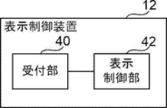
- the diagnostic support system 10 includes a display control device 12, a photographing device 14, and an image storage device 16.
- the display control device 12, the photographing device 14, and the image storage device 16 are each connected to the network N, and can communicate with each other via the network N.
- the imaging device 14 is an apparatus that generates a three-dimensional medical image representing the site by photographing the site to be diagnosed of the subject.
- the three-dimensional medical image taken by the imaging device 14 includes a plurality of tomographic images.
- a CT device is applied as the photographing device 14
- the present invention is not limited to this.
- a device that generates a three-dimensional medical image other than a CT device such as an MRI device or a PET (Positron Emission Tomography) device may be applied.
- a tomographic image of an axial cross section is applied as a tomographic image constituting a three-dimensional medical image
- the present invention is not limited to this.
- a tomographic image constituting a three-dimensional medical image a tomographic image of a cross section other than the axial cross section such as a sagittal cross section and a coronal cross section may be applied.
- the image storage device 16 is a computer that stores and manages medical images, and includes a storage device for storing medical images and the like.
- the image storage device 16 transmits / receives a medical image generated by the imaging device 14 between the display control device 12 and the imaging device 14 via the network N.
- the storage format of medical images and communication between each device via network N are based on a predetermined protocol such as DICOM (Digital Imaging and Communication in Medicine).
- Examples of the display control device 12 include a personal computer, a server computer, and the like.
- the display control device 12 may be a cloud server.
- the display control device 12 includes a CPU (Central Processing Unit) 20, a memory 21 as a temporary storage area, and a non-volatile storage unit 22. Further, the display control device 12 includes a display 23 such as a liquid crystal display, an input unit 24 such as a keyboard and a mouse, and a network I / F (InterFace) 25 connected to the network N.
- the CPU 20, the memory 21, the storage unit 22, the display 23, the input unit 24, and the network I / F 25 are connected to the bus 26.
- the storage unit 22 is realized by an HDD (Hard Disk Drive), an SSD (Solid State Drive), a flash memory, or the like.
- the display control program 30 is stored in the storage unit 22 as a storage medium.
- the CPU 20 reads the display control program 30 from the storage unit 22, expands it into the memory 21, and executes the expanded display control program 30.
- the display control device 12 includes a reception unit 40 and a display control unit 42.
- the CPU 20 executes the display control program 30, it functions as the reception unit 40 and the display control unit 42.
- the reception unit 40 receives various instructions input by the user via the input unit 24. Details of various instructions by this user will be described later.
- the display control unit 42 has a slider bar SB for designating a tomographic position corresponding to each of a plurality of medical tomographic images obtained by photographing the subject, and a designated tomographic position.
- the tomographic image corresponding to the above is controlled to be displayed on the display 23.
- the plurality of medical tomographic images obtained by photographing the subject constitute a three-dimensional medical image designated as a display target among the three-dimensional medical images stored in the image storage device 16. It is a tomographic image group.
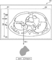
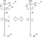
- the screen displayed on the display 23 includes a display area A1 for displaying the slider bar SB and a display area A2 for displaying the tomographic image.
- the user-granted information given by the user and the computer-granted information given by the computer are set to be given to each tomographic image.
- the given information means the given information unique to each tomographic image in which the given information given to each tomographic image and the mark to be described later corresponding to the given information are linked one-to-one. ..
- Examples of the user-assigned information include bookmarks given by the user as markers for the tomographic image that the user wants to see later, and annotations such as information on the region of interest (ROI) included in the tomographic image.
- examples of the computer-aided information include information on the region of interest detected by CAD (Computer-Aided Diagnosis) or information on the region of interest detected by AI (Artificial Intelligence) diagnostic imaging.
- the area of interest here means an area of interest to the user, such as an area of a lesion such as a tumor.
- examples of information regarding the region of interest include the contour, position, area, and the like of the region of interest.
- the number of computers to which the computer-assigned information is given may be one or a plurality of computers.
- the computer to which the computer-assigned information is given may be the display control device 12, the control device included in the photographing device 14, or the image storage device 16. Further, a computer such as an external image processing device of the diagnosis support system 10 may be used.
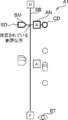
- FIG. 5 shows only the display area A1 out of the display area A1 and the display area A2 shown in FIG.
- the display control unit 42 controls to display the slider SD at a position along the longitudinal direction of the slider bar SB corresponding to the designated fault position.
- the “H” surrounded by the rectangle represents the head side of the subject
- the “F” surrounded by the rectangle represents the foot side. That is, the position of the slider SD on the slider bar SB represents the tomographic position on the cranial side as it approaches "H” among the tomographic positions of each tomographic image constituting the three-dimensional medical image, and as it approaches "F". It represents the fault position on the foot side.
- FIG. 5 shows only the display area A1 out of the display area A1 and the display area A2 shown in FIG.
- the display control unit 42 controls to display the slider SD at a position along the longitudinal direction of the slider bar SB corresponding to the designated fault position.
- the “H” surrounded by the rectangle represents the head side of the subject
- the slider bar SB and the slider SD are examples of designated objects for designating tomographic positions corresponding to each of a plurality of tomographic images.
- the display control unit 42 attaches a mark indicating the given information to the tomographic image to which the given information is given, and a mark that can identify one tomographic image by one mark is given to the tomographic image. Control is performed to display at the position of the slider bar SB corresponding to the tomographic position of the image.
- the display control unit 42 controls the display control unit 42 to display the mark BM representing the bookmark at the position of the slider bar SB corresponding to the tomographic position of the assigned tomographic image for the tomographic image to which the bookmark is attached. I do. Further, the display control unit 42 controls that the annotated tomographic image is displayed with the mark AN representing the annotation at the position of the slider bar SB corresponding to the tomographic position of the annotated tomographic image. Further, the display control unit 42 displays a mark CD representing the computer-assigned information at the position of the slider bar SB corresponding to the tomographic position of the assigned tomographic image for the tomographic image to which the computer-assigned information is added. Take control.
- the display control unit 42 controls to display each mark at the position of the slider bar SB corresponding to the fault position by shifting the mark along the direction orthogonal to the longitudinal direction of the slider bar SB (that is, the longitudinal direction of the slider SD). conduct. As a result, even if there are multiple marks at the same fault position, the marks do not overlap.
- the display control unit 42 controls to display the button BT for accepting the input for switching the display and non-display of the computer-assigned information by the user.
- the user specifies the tomographic position of the tomographic image to be displayed via the input unit 24. For example, the user specifies the tomographic position by dragging the slider SD to the tomographic position of the tomographic image to be displayed on the slider bar SB. Further, for example, the user specifies the tomographic position of the tomographic image to be displayed on the slider bar SB by scrolling the mouse wheel.
- the display control unit 42 controls to highlight the mark indicating the given information when the given information is given to the tomographic image corresponding to the designated tomographic position. For example, as shown in FIG. 6, the display control unit 42 highlights the outline of the mark corresponding to the designated fault position by displaying it thicker than the mark corresponding to the undesignated fault position. I do.
- FIG. 6 shows an example in which bookmarks, annotations, and computer-assigned information are added to the tomographic image corresponding to the specified tomographic position.
- the display control unit 42 controls to highlight the color of the outline of the mark corresponding to the designated fault position by making it different from the color of the outline of the mark corresponding to the non-designated fault position. You may go. Further, for example, the display control unit 42 may control highlighting by blinking only the mark corresponding to the designated fault position. The form of such highlighting is an example, and other forms may be used.
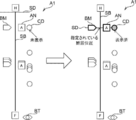
- the display control unit 42 includes a mark CD (indicated as “undisplayed” on the left side of FIG. 7) representing computer-assigned information assigned to the undisplayed tomographic image, and the displayed tomographic image. Control is performed to identifiablely display the mark CD (indicated as "displayed” on the right side of FIG. 7) representing the computer-assigned information given to the image. Specifically, for example, when the background color is black, the display control unit 42 fills the mark CD representing the computer-assigned information given to the undisplayed tomographic image with a relatively bright color (for example, orange). To display.
- a relatively bright color for example, orange
- the color of the mark CD given to the displayed tomographic image is changed to a color close to the background color (for example,). Change to light gray) and display.
- the user can grasp at a glance whether or not the computer-assigned information has been confirmed, that is, whether or not the region of interest detected by the computer has been confirmed.
- the display control unit 42 controls to display the computer-assigned information on the tomographic image for the tomographic image to which the computer-assigned information is added. Specifically, for example, the display control unit 42 controls to display the region of interest represented by the computer-assigned information in a state of being filled with a color different from other regions (for example, orange). In addition, the computer-assigned information is displayed without a contour line in the initial state.
- the display control unit 42 controls to display the annotation on the tomographic image with respect to the tomographic image to which the annotation is added. Specifically, for example, the display control unit 42 controls to display the outline of the region of interest represented by the annotation in a color (for example, white) different from the region of interest represented by the computer-assigned information. Therefore, the user can grasp whether the region of interest displayed on the tomographic image is detected by the user operation or by the computer.
- the outline of the region of interest represented by the annotation, and the outline of the white solid line is represented by a broken line.
- a button designated by the user when the computer-assigned information is correct (“agree” button in the example of FIG. 8).
- control to display a button specified by the user (“disagree” button in the example of FIG. 8) when the computer-assigned information is incorrect.
- the case where the computer-assigned information is correct or incorrect means a case where the user determines that the information is correct or incorrect.
- the outline of the region of interest represented by the computer-assigned information is correct, the user specifies an "agree” button via the input unit 24.
- the outline of the region of interest represented by the computer-assigned information is incorrect, the user specifies a "disagree” button via the input unit 24.
- the display control unit 42 When the reception unit 40 receives an input indicating that the computer-assigned information is incorrect, that is, when the "disagree" button is specified, the display control unit 42 performs the following control. In this case, as shown in FIG. 9, the display control unit 42 controls to change the color of the mark CD representing the computer-assigned information from the current display color to a color close to the background color. Specifically, the display control unit 42 controls to change the color of the mark CD from gray, which indicates that the mark CD has been displayed, to dark gray, which is close to black, which is the background color. As a result, although the information is given by the computer, the information unnecessary for the user can be made inconspicuous.
- the display control unit 42 When the reception unit 40 receives an input indicating that the computer-assigned information is correct, that is, when the "agree" button is specified, the display control unit 42 performs the following control. In this case, the display control unit 42 controls to add annotations to the tomographic image to which the computer-assigned information designated as correct is added. Therefore, the outline of the region of interest represented by the computer-assigned information designated as correct is displayed as an annotation, for example, in white. In this case, since the computer-granted information is still given, the user determines whether the area of interest is not detected by the computer and is specified by the user, or is the area of interest detected by the computer and determined to be correct by the computer. Can be grasped.
- Computer detection may detect a large number of areas of interest. Therefore, the user may want to hide the computer-assigned information in the image diagnosis.
- the user wants to switch the display / non-display of the computer-assigned information, the user specifies the button BT via the input unit 24.
- the display control unit 42 displays a mark CD representing the computer-assigned information according to the received input, as shown in FIG. And control to switch between non-display. Further, in the present embodiment, as shown in FIG. 11, the display control unit 42 also controls to switch the display / non-display of the computer-assigned information on the tomographic image in addition to the mark CD.
- the display control process is executed, for example, when the user inputs an execution instruction and identification information capable of identifying a tomographic image group constituting a three-dimensional medical image to be displayed via the input unit 24.
- the display control unit 42 acquires a tomographic image group specified according to the input identification information from the image storage device 16, and displays an initial screen on the display 23 based on the acquired tomographic image group. Take control. Specifically, as described above, the display control unit 42 includes a slider bar SB for designating the tomographic position corresponding to each of the acquired tomographic image groups, a tomographic image corresponding to the designated tomographic image group, and the tomographic image. Is controlled to be displayed on the display 23. Further, as described above, the display control unit 42 controls to display the slider SD at a position along the longitudinal direction of the slider bar SB corresponding to the designated fault position.
- the fault position on the foot side may be applied or the central fault position may be applied as the specified fault position.
- the display control unit 42 corresponds to the tomographic position of the tomographic image to which the tomographic image is given, with the mark indicating the given information for the tomographic image to which the tomographic image is given. Controls the display at the position of the slider bar SB. In addition, the display control unit 42 controls the display of the button BT for accepting the input for switching the display and non-display of the computer-assigned information by the user.
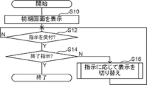
- step S10 the screen shown in FIG. 4 is displayed on the display 23 as an example.
- step S10 is executed from the second time onward, the display control unit 42 takes over the latest display state.
- step S12 the reception unit 40 waits until the instruction input by the user via the input unit 24 is received.
- the determination in step S12 becomes an affirmative determination, and the process proceeds to step S14.
- step S14 the reception unit 40 determines whether or not the instruction received in step S12 is an instruction to end the display. If this determination is a negative determination, the process proceeds to step S16.
- step S16 the display control unit 42 controls to switch the display according to the instruction received in step S12. When the process of step S16 is completed, the process returns to step S12. On the other hand, if the determination in step S14 is a negative determination, the display control process ends.
- the display state of each display object displayed in the display area A1 and the display area A2 at the time when the display control process is completed is stored in the image storage device 16 in association with the tomographic image group, and is stored for the second time.
- step S10 is subsequently executed, the display state is inherited.
- step S12 If the instruction received in step S12 is an instruction to specify the fault position by dragging the slider SD or scrolling the mouse wheel, the processing routine shown in FIG. 13 is executed in step S16.
- step S20 of FIG. 13 the display control unit 42 controls to move the slider SD to the position of the slider bar SB corresponding to the fault position designated by the user operation.
- step S22 the display control unit 42 controls to switch the tomographic image of the display area A2 to the tomographic image at the designated tomographic position.
- step S24 the display control unit 42 determines whether or not the given information is given to the tomographic image of the designated tomographic position. If this determination is affirmative, the process proceeds to step S26. In step S26, the display control unit 42 determines whether or not a bookmark is added to the tomographic image at the designated tomographic position. If this determination is affirmative, the process proceeds to step S28.
- step S28 the display control unit 42 controls to highlight the mark BM representing the bookmark attached to the tomographic image at the designated tomographic position. If the determination in step S26 is a negative determination, the process in step S28 is not executed and the process proceeds to step S30.
- step S30 the display control unit 42 determines whether or not the tomographic image at the designated tomographic position is annotated. If this determination is affirmative, the process proceeds to step S32. In step S32, the display control unit 42 controls to highlight the mark AN representing the annotation attached to the tomographic image at the designated tomographic position. In step S34, the display control unit 42 controls to display the annotation on the tomographic image as described above. If the determination in step S30 is a negative determination, the processes from step S32 to step S34 are not executed and the process proceeds to step S36.
- step S36 the display control unit 42 determines whether or not the computer-assigned information is added to the tomographic image of the designated tomographic position. If this determination is affirmative, the process proceeds to step S38.
- step S38 the display control unit 42 controls to highlight the mark CD representing the computer-assigned information given to the tomographic image at the designated tomographic position.
- step S40 as described above, the display control unit 42 changes the color of the mark CD representing the computer-assigned information given to the tomographic image of the designated tomographic position to a color indicating that it has been displayed. ..
- step S42 the display control unit 42 controls to display the computer-assigned information on the tomographic image as described above.
- step S42 When the process of step S42 is completed, the process routine shown in FIG. 13 ends. If the determination in step S36 is a negative determination, the processing routines shown in FIG. 13 are terminated without executing the processes from step S38 to step S42. If the determination in step S24 is a negative determination, the processing routines shown in FIG. 13 are terminated without executing the processes from step S26 to step S42.
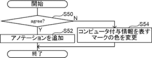
- step S12 If the instruction received in step S12 is an instruction indicating whether the computer-granted information specified by the "agree” button or the "disagree” button is correct or incorrect, the processing routine shown in FIG. 14 is executed in step S16. ..
- step S50 of FIG. 14 the reception unit 40 determines whether or not the received instruction is an input indicating that the computer-assigned information is correct, that is, whether or not the "agree" button is specified. If this determination is affirmative, the process proceeds to step S52. If the instruction received by the reception unit 40 is an input indicating that the computer-assigned information is incorrect, that is, if the "disagree" button is specified, the determination in step S50 becomes a negative determination, and the process proceeds to step S54. Transition.
- step S52 the display control unit 42 controls to add annotations to the tomographic image to which the computer-assigned information designated as correct is added.
- step S54 the display control unit 42 controls to change the color of the mark CD representing the computer-assigned information from the current display color to a color close to the background color.
- step S12 If the instruction received in step S12 is an instruction to switch the display / non-display of the computer-assigned information by designating the button BT, the processing routine shown in FIG. 15 is executed in step S16.
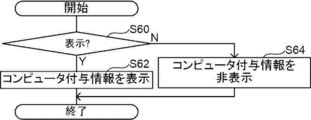
- step S60 of FIG. 15 the reception unit 40 determines whether or not the received instruction is an instruction for displaying computer-assigned information. If this determination is affirmative, the process proceeds to step S62. If the instruction received by the reception unit 40 is an instruction to hide the computer-assigned information, the determination in step S60 becomes a negative determination, and the process proceeds to step S64.
- step S62 the display control unit 42 controls to hide the mark CD representing the computer-assigned information and hide the computer-assigned information on the tomographic image.
- step S64 the display control unit 42 controls to display the mark CD representing the computer-assigned information and to display the computer-assigned information on the tomographic image.
- one tomographic image can be specified by one mark, and it corresponds to a designated tomographic position.
- the mark indicating the given information is highlighted. Therefore, it is easy for the user to grasp whether or not unique addition information is added to the tomographic image corresponding to the tomographic position designated on the slider bar SB.
- the display control unit 42 is designated from one end of the slider bar SB to the designated fault position and from the other end without displaying the slider SD. Control may be performed to display the slider bar SB in a different color from that up to the fault position. In this case, it is not necessary to display the slider SD, which is a dedicated object for designating the fault position. However, in this case, the slider SD may also be displayed as in the above embodiment.
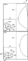
- the display control unit 42 has the outline of the region of interest represented by the computer-assigned information given to the tomographic image with respect to the tomographic image to which the computer-assigned information is added.
- control may be performed to further display the contour O2 of the region of interest.
- the display control unit 42 controls the contour O2 to display the contour of the region of interest represented by the computer-assigned information assigned to any of the other tomographic images in which the same region of interest is detected.
- the display control unit 42 sets the maximum contour of the contour of the region of interest represented by the computer-assigned information given to any of the other tomographic images in which the same region of interest is detected as the contour O2. Control the display.
- Examples of the maximum contour referred to here include a contour having the largest area, a contour having the longest contour length, and the like.
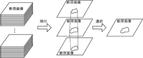
- a computer extracts a tomographic image group showing the same object (for example, a region of interest) from a plurality of tomographic images constituting a three-dimensional medical image, and the extracted tomographic image group A representative tomographic image may be selected from the images, and computer-assigned information may be added only to the selected tomographic image.
- the computer in this case, for example, in a continuous tomographic image, the computer has a first value in which the absolute value of the difference in the position of the center of gravity of the detected region of interest is equal to or less than a predetermined first threshold value and the absolute value of the difference in area is predetermined. Areas of interest below two thresholds are identified as the same area of interest.
- the first threshold value and the second threshold value in this case, preset values can be applied as the upper limit values of the differences between the same regions of interest in continuous tomographic images.
- the computer uses a tomographic image in which the region of interest having the largest area or the longest contour length is detected from the extracted tomographic image group as a representative tomographic image. Extract.
- the computer in this case may be a display control device 12, a control device included in the photographing device 14, an image storage device 16, or a computer outside the diagnosis support system 10.
- the process selected as the tomographic image to which the given information is given by the computer may be performed by the user via the input unit 24 in the same manner.
- the user-granted information in this case is information given by the user to a tomographic image that is a representative of a tomographic image group in which the same object is captured, among a plurality of tomographic images.
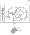
- a schema SM and a slider SD may be applied as a designated object for designating a tomographic position corresponding to each of a plurality of tomographic images.
- the schema SM referred to here means a schematic diagram schematically showing a part of the human body.
- FIG. 19 shows an example in which a plurality of medical tomographic images obtained by tomosynthesis imaging using a mammography apparatus are applied as a plurality of tomographic images. The upper part of FIG.
- FIG. 19 shows a tomographic image obtained by performing MLO (Medio-Lateral Oblique) imaging on the right breast, and the lower part shows CC (Cranio-Caudal) imaging on the right breast.
- the tomographic image obtained by is shown.
- the depth direction of the tomographic image that is, the moving direction of the slider SD is indicated by a broken double arrow.
- the user specifies the tomographic position by dragging the slider SD to the tomographic position of the tomographic image to be displayed on the schema SM.
- the mark indicating the given information is highlighted.
- the mark AN and the mark CD may be displayed in the schema SM so that the two-dimensional arrangement when the breast is viewed from the front can be seen.
- both the slider SD and the slider bar SB shown in FIGS. 4 and 5 and the schema SM and the slider SD shown in FIG. 19 may be displayed in the display area A1. Further, in this embodiment, the operation performed on one of these may be reflected in conjunction with the other.
- the various processors include a CPU, which is a general-purpose processor that executes software (program) and functions as various processing units, and a circuit after manufacturing an FPGA (Field Programmable Gate Array) or the like.
- Dedicated electricity which is a processor with a circuit configuration specially designed to execute specific processing such as programmable logic device (PLD), ASIC (Application Specific Integrated Circuit), which is a processor whose configuration can be changed. Circuits and the like are included.
- One processing unit may be composed of one of these various processors, or a combination of two or more processors of the same type or different types (for example, a combination of a plurality of FPGAs or a combination of a CPU and an FPGA). It may be composed of a combination). Further, a plurality of processing units may be configured by one processor.
- one processor is configured by a combination of one or more CPUs and software, as represented by a computer such as a client and a server.
- a processor functions as a plurality of processing units.
- SoC System On Chip
- the various processing units are configured by using one or more of the above-mentioned various processors as a hardware structure.
- an electric circuit in which circuit elements such as semiconductor elements are combined can be used.
- the display control program 30 is provided in a form recorded on a recording medium such as a CD-ROM (Compact Disc Read Only Memory), a DVD-ROM (Digital Versatile Disc Read Only Memory), and a USB (Universal Serial Bus) memory. May be good. Further, the display control program 30 may be downloaded from an external device via a network.
- a recording medium such as a CD-ROM (Compact Disc Read Only Memory), a DVD-ROM (Digital Versatile Disc Read Only Memory), and a USB (Universal Serial Bus) memory. May be good.
- the display control program 30 may be downloaded from an external device via a network.
Landscapes
- Engineering & Computer Science (AREA)
- Theoretical Computer Science (AREA)
- Physics & Mathematics (AREA)
- General Engineering & Computer Science (AREA)
- General Physics & Mathematics (AREA)
- Health & Medical Sciences (AREA)
- Life Sciences & Earth Sciences (AREA)
- Human Computer Interaction (AREA)
- Medical Informatics (AREA)
- Nuclear Medicine, Radiotherapy & Molecular Imaging (AREA)
- Pathology (AREA)
- Surgery (AREA)
- Radiology & Medical Imaging (AREA)
- Biomedical Technology (AREA)
- Heart & Thoracic Surgery (AREA)
- High Energy & Nuclear Physics (AREA)
- Molecular Biology (AREA)
- Biophysics (AREA)
- Animal Behavior & Ethology (AREA)
- General Health & Medical Sciences (AREA)
- Public Health (AREA)
- Veterinary Medicine (AREA)
- Optics & Photonics (AREA)
- Magnetic Resonance Imaging Apparatus (AREA)
- Apparatus For Radiation Diagnosis (AREA)
Priority Applications (4)
| Application Number | Priority Date | Filing Date | Title |
|---|---|---|---|
| JP2022505744A JP7510495B2 (ja) | 2020-03-09 | 2020-09-28 | 表示制御装置、表示制御方法、及び表示制御プログラム |
| US17/819,358 US11983801B2 (en) | 2020-03-09 | 2022-08-12 | Display control apparatus, display control method, and display control program |
| US18/630,840 US12277629B2 (en) | 2020-03-09 | 2024-04-09 | Display control apparatus, display control method, and display control program |
| JP2024100685A JP7763900B2 (ja) | 2020-03-09 | 2024-06-21 | 表示制御装置、表示制御方法、及び表示制御プログラム |
Applications Claiming Priority (2)
| Application Number | Priority Date | Filing Date | Title |
|---|---|---|---|
| JP2020-040359 | 2020-03-09 | ||
| JP2020040359 | 2020-03-09 |
Related Child Applications (1)
| Application Number | Title | Priority Date | Filing Date |
|---|---|---|---|
| US17/819,358 Continuation US11983801B2 (en) | 2020-03-09 | 2022-08-12 | Display control apparatus, display control method, and display control program |
Publications (1)
| Publication Number | Publication Date |
|---|---|
| WO2021181731A1 true WO2021181731A1 (ja) | 2021-09-16 |
Family
ID=77671511
Family Applications (1)
| Application Number | Title | Priority Date | Filing Date |
|---|---|---|---|
| PCT/JP2020/036595 Ceased WO2021181731A1 (ja) | 2020-03-09 | 2020-09-28 | 表示制御装置、表示制御方法、及び表示制御プログラム |
Country Status (3)
| Country | Link |
|---|---|
| US (2) | US11983801B2 (enExample) |
| JP (2) | JP7510495B2 (enExample) |
| WO (1) | WO2021181731A1 (enExample) |
Cited By (2)
| Publication number | Priority date | Publication date | Assignee | Title |
|---|---|---|---|---|
| WO2023048268A1 (ja) * | 2021-09-27 | 2023-03-30 | 富士フイルム株式会社 | 情報処理装置、情報処理方法及び情報処理プログラム |
| JP2024111254A (ja) * | 2020-03-09 | 2024-08-16 | 富士フイルム株式会社 | 表示制御装置、表示制御方法、及び表示制御プログラム |
Families Citing this family (2)
| Publication number | Priority date | Publication date | Assignee | Title |
|---|---|---|---|---|
| CN113961124B (zh) * | 2021-09-27 | 2024-02-27 | 上海联影医疗科技股份有限公司 | 医学图像显示方法、装置、计算机设备和存储介质 |
| EP4468307A1 (en) * | 2023-05-25 | 2024-11-27 | Koninklijke Philips N.V. | Workflow interfaces driven by artificial intelligence results |
Citations (4)
| Publication number | Priority date | Publication date | Assignee | Title |
|---|---|---|---|---|
| JP2008006187A (ja) * | 2006-06-30 | 2008-01-17 | Fujifilm Corp | 医用画像表示処理装置、及び、医用画像表示処理プログラム |
| US20100141654A1 (en) * | 2008-12-08 | 2010-06-10 | Neemuchwala Huzefa F | Device and Method for Displaying Feature Marks Related to Features in Three Dimensional Images on Review Stations |
| WO2014203940A1 (ja) * | 2013-06-18 | 2014-12-24 | キヤノン株式会社 | トモシンセシス撮影の制御装置、撮影装置、撮影システム、制御方法および当該制御方法をコンピュータに実行させるためのプログラム |
| JP2015198928A (ja) * | 2014-03-31 | 2015-11-12 | 株式会社東芝 | 医用画像処理装置、および医用画像処理システム |
Family Cites Families (7)
| Publication number | Priority date | Publication date | Assignee | Title |
|---|---|---|---|---|
| JP2004173910A (ja) | 2002-11-27 | 2004-06-24 | Fuji Photo Film Co Ltd | 画像表示装置 |
| WO2008001928A1 (en) | 2006-06-30 | 2008-01-03 | Fujifilm Corporation | Medical image display apparatus and medical image display program |
| JP6419441B2 (ja) | 2014-03-11 | 2018-11-07 | キヤノンメディカルシステムズ株式会社 | 医用画像処理装置、医用画像処理システム、および医用画像処理プログラム |
| JP6258084B2 (ja) * | 2014-03-12 | 2018-01-10 | 東芝メディカルシステムズ株式会社 | 医用画像表示装置、医用画像表示システムおよび医用画像表示プログラム |
| US11344371B2 (en) * | 2018-10-19 | 2022-05-31 | Canon U.S.A., Inc. | Visualization of three-dimensional image data on a two-dimensional image |
| JP2020099612A (ja) * | 2018-12-25 | 2020-07-02 | 小林製薬株式会社 | 嗅覚検査具、嗅覚検査キット及び嗅覚検査方法 |
| WO2021181731A1 (ja) * | 2020-03-09 | 2021-09-16 | 富士フイルム株式会社 | 表示制御装置、表示制御方法、及び表示制御プログラム |
-
2020
- 2020-09-28 WO PCT/JP2020/036595 patent/WO2021181731A1/ja not_active Ceased
- 2020-09-28 JP JP2022505744A patent/JP7510495B2/ja active Active
-
2022
- 2022-08-12 US US17/819,358 patent/US11983801B2/en active Active
-
2024
- 2024-04-09 US US18/630,840 patent/US12277629B2/en active Active
- 2024-06-21 JP JP2024100685A patent/JP7763900B2/ja active Active
Patent Citations (4)
| Publication number | Priority date | Publication date | Assignee | Title |
|---|---|---|---|---|
| JP2008006187A (ja) * | 2006-06-30 | 2008-01-17 | Fujifilm Corp | 医用画像表示処理装置、及び、医用画像表示処理プログラム |
| US20100141654A1 (en) * | 2008-12-08 | 2010-06-10 | Neemuchwala Huzefa F | Device and Method for Displaying Feature Marks Related to Features in Three Dimensional Images on Review Stations |
| WO2014203940A1 (ja) * | 2013-06-18 | 2014-12-24 | キヤノン株式会社 | トモシンセシス撮影の制御装置、撮影装置、撮影システム、制御方法および当該制御方法をコンピュータに実行させるためのプログラム |
| JP2015198928A (ja) * | 2014-03-31 | 2015-11-12 | 株式会社東芝 | 医用画像処理装置、および医用画像処理システム |
Cited By (3)
| Publication number | Priority date | Publication date | Assignee | Title |
|---|---|---|---|---|
| JP2024111254A (ja) * | 2020-03-09 | 2024-08-16 | 富士フイルム株式会社 | 表示制御装置、表示制御方法、及び表示制御プログラム |
| JP7763900B2 (ja) | 2020-03-09 | 2025-11-04 | 富士フイルム株式会社 | 表示制御装置、表示制御方法、及び表示制御プログラム |
| WO2023048268A1 (ja) * | 2021-09-27 | 2023-03-30 | 富士フイルム株式会社 | 情報処理装置、情報処理方法及び情報処理プログラム |
Also Published As
| Publication number | Publication date |
|---|---|
| JP7763900B2 (ja) | 2025-11-04 |
| JP7510495B2 (ja) | 2024-07-03 |
| US20220392124A1 (en) | 2022-12-08 |
| US12277629B2 (en) | 2025-04-15 |
| US11983801B2 (en) | 2024-05-14 |
| JP2024111254A (ja) | 2024-08-16 |
| JPWO2021181731A1 (enExample) | 2021-09-16 |
| US20240257416A1 (en) | 2024-08-01 |
Similar Documents
| Publication | Publication Date | Title |
|---|---|---|
| JP7763900B2 (ja) | 表示制御装置、表示制御方法、及び表示制御プログラム | |
| US20190267132A1 (en) | Medical image display device, method, and program | |
| US11093699B2 (en) | Medical image processing apparatus, medical image processing method, and medical image processing program | |
| US12307561B2 (en) | Display control apparatus, display control method, and display control program | |
| JP7701493B2 (ja) | 医用画像処理装置、方法およびプログラム | |
| US12170140B2 (en) | Customizable multimodality image hanging protocols | |
| WO2022215530A1 (ja) | 医用画像装置、医用画像方法、及び医用画像プログラム | |
| JP6843785B2 (ja) | 診断支援システム、診断支援方法、及びプログラム | |
| US10324582B2 (en) | Medical image display apparatus, method for controlling the same | |
| JP7650345B2 (ja) | 画像処理装置、画像表示システム、画像処理装置の作動方法及びプログラム | |
| JP2005185405A (ja) | 医用画像処理装置、関心領域抽出方法、ならびに、プログラム | |
| CN102656586B (zh) | 将采集的图像与对象相关联的方法和系统 | |
| US20230281810A1 (en) | Image display apparatus, method, and program | |
| US20230225681A1 (en) | Image display apparatus, method, and program | |
| WO2023048267A1 (ja) | 情報処理装置、情報処理方法及び情報処理プログラム | |
| WO2023048268A1 (ja) | 情報処理装置、情報処理方法及び情報処理プログラム | |
| JP7710071B2 (ja) | 画像処理装置、画像表示システム、画像処理装置の作動方法及びプログラム | |
| US20230143966A1 (en) | Image processing apparatus and non-transitory computer readable medium | |
| WO2025216242A1 (ja) | 表示制御装置、表示制御方法、及び表示制御プログラム | |
| JP2024140470A (ja) | 画像処理装置、画像処理方法、画像処理プログラム、学習装置、学習方法、及び学習プログラム | |
| WO2022220081A1 (ja) | 文書作成支援装置、文書作成支援方法、及び文書作成支援プログラム | |
| JP2024140469A (ja) | 画像処理装置、画像処理方法、及び画像処理プログラム | |
| WO2022270151A1 (ja) | 画像処理装置、方法およびプログラム | |
| JP2023047909A (ja) | 医用画像表示装置、方法およびプログラム | |
| JP2024101315A (ja) | 画像解析支援装置、画像解析支援システム、画像解析支援方法及び画像解析支援プログラム |
Legal Events
| Date | Code | Title | Description |
|---|---|---|---|
| 121 | Ep: the epo has been informed by wipo that ep was designated in this application |
Ref document number: 20924557 Country of ref document: EP Kind code of ref document: A1 |
|
| ENP | Entry into the national phase |
Ref document number: 2022505744 Country of ref document: JP Kind code of ref document: A |
|
| NENP | Non-entry into the national phase |
Ref country code: DE |
|
| 122 | Ep: pct application non-entry in european phase |
Ref document number: 20924557 Country of ref document: EP Kind code of ref document: A1 |