WO2021181703A1 - 空気調和機、空気調和機の通信制御プログラム、および、無線通信方法 - Google Patents
空気調和機、空気調和機の通信制御プログラム、および、無線通信方法 Download PDFInfo
- Publication number
- WO2021181703A1 WO2021181703A1 PCT/JP2020/011273 JP2020011273W WO2021181703A1 WO 2021181703 A1 WO2021181703 A1 WO 2021181703A1 JP 2020011273 W JP2020011273 W JP 2020011273W WO 2021181703 A1 WO2021181703 A1 WO 2021181703A1
- Authority
- WO
- WIPO (PCT)
- Prior art keywords
- router
- air conditioner
- mode
- connection information
- pairing
- Prior art date
- Legal status (The legal status is an assumption and is not a legal conclusion. Google has not performed a legal analysis and makes no representation as to the accuracy of the status listed.)
- Ceased
Links
Images





Classifications
-
- F—MECHANICAL ENGINEERING; LIGHTING; HEATING; WEAPONS; BLASTING
- F24—HEATING; RANGES; VENTILATING
- F24F—AIR-CONDITIONING; AIR-HUMIDIFICATION; VENTILATION; USE OF AIR CURRENTS FOR SCREENING
- F24F11/00—Control or safety arrangements
- F24F11/50—Control or safety arrangements characterised by user interfaces or communication
- F24F11/56—Remote control
- F24F11/58—Remote control using Internet communication
Definitions
- the present invention relates to an air conditioner having a wireless communication function, a communication control program for the air conditioner, and a wireless communication method.
- Patent Document 1 describes an invention in which one-to-one communication is performed and pairing is performed using, for example, a short-range communication function (infrared communication or the like) mounted on a smartphone or the like.
- an object of the present invention is to shift to a pairing mode when a connection to a new router is required in an air conditioner equipped with a wireless LAN (Local Area Network) function.
- LAN Local Area Network
- the air conditioner of the present invention is paired with a router via a wireless communication path, and is connected to the paired router with a wireless communication unit that communicates with the paired router. If the connection information is not stored in the storage unit that stores the connection information of the above and the storage unit after the power is turned on, the mode shifts to the pairing mode for connecting to the desired router and the connection is connected to the storage unit. It is characterized by including a control unit that does not transition to the pairing mode if the information is stored.
- the communication control program of the air conditioner of the present invention is a process of pairing a computer provided with a wireless communication unit with a router via a wireless communication path, a process of communicating with the paired router, or pairing with any router.
- the wireless communication unit pairs with a router via a wireless communication path
- the paired step communicates with the router
- the control unit pairs with any router.
- the present embodiment relates to a remote control system.
- This remote control system is compatible with, for example, the Home Energy Management System, and manages to save energy used at home.
- the remote control system 700 will be described with reference to FIGS. 1 and 2. Note that FIGS. 1 and 2 are examples of remote control systems, and various configurations can be considered.
- FIG. 1 is a conceptual diagram showing a device configuration of the remote control system 700.
- the remote control system 700 of the present embodiment uses the operation terminal 100 to refrigerate cycle devices such as an air conditioner 400 (air conditioner, controlled device) and a heat pump water heater (not shown) from outside the house 1 to inside the house 3.
- the remote control system 700 is mainly constructed of an air conditioner 400 equipped with a dedicated server 600 connected from the operation terminal 100 via the Internet 10 and a wireless LAN module 300 of the home 3.
- the infrared remote controller 800 of FIG. 1 is not essential for the remote control system 700.
- the refrigeration cycle device of the present embodiment will be described by taking the air conditioner 400 as an example.
- the present invention is not limited to air conditioners, and may be applied to any electronic device.
- a home gateway 20 (HGW) and a router 21 are installed in the house 3.
- the router 21 can communicate with the operation terminal 100 and the wireless LAN module 300 in the house 3 by wire or wirelessly.
- the operation terminal 100 can communicate with the dedicated server 600 connected to the Internet 10.
- the dedicated server 600 can communicate with the air conditioner 400.
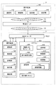
- FIG. 2 is a detailed view showing the device configuration of the remote control system 700. The details of each device will be described with reference to FIG. ⁇ Controlled equipment >>
- the air conditioner 400 is a controlled device, and is composed of a control unit 410, an air conditioner unit 420, a display unit 430, a storage unit 440, an infrared light receiving unit 450, and a wireless LAN module 300.
- the control unit 410 is a processor that controls the air conditioner 400 in an integrated manner.
- the air-conditioning unit 420 is a portion that is air-conditioned by, for example, a refrigeration cycle, and is controlled by the control unit 410.
- the display unit 430 displays the state of the air conditioner 400 by means of an LED (Light Emitting Diode) or the like. The user can visually recognize the state of the air conditioner 400 by the display unit 430.
- a connection information sticker is attached to the housing of the air conditioner 400. On this connection information sticker, its own SSID (Service Set Identifier) and password are described, and a two-dimensional code in which these SSID and password are encoded is printed. The details of this connection information seal will be described later with reference to FIG.
- FIG. 3 is a diagram showing a display unit 430 of the air conditioner 400.
- the display unit 430 includes a remote lamp 431, a cleaning lamp 432, a clean lamp 433, an ECO lamp 434, an operation lamp 435, a timer lamp 436, an auto-off lamp 437, and a Mihari lamp 438.
- the operation lamp 435 is a green LED
- the timer lamp 436 is an orange LED
- the others are yellow LEDs.
- the remote lamp 431 indicates that the remote control function is effective.
- the remote control function refers to a function of operating the air conditioner 400 or acquiring the state of the air conditioner 400 via a wireless communication path.
- the cleaning lamp 432 indicates that the indoor unit or the outdoor unit is being freeze-cleaned.
- the clean lamp 433 indicates that the filter is being cleaned or mold is being suppressed inside the indoor unit.
- the ECO lamp 434 indicates that the eco-driving is in progress.
- the operation lamp 435 indicates that the air conditioner 400 is in operation.
- the timer lamp 436 indicates that the timer is reserved.
- the auto-off lamp 437 indicates that the auto-off setting is in progress.
- the Mihari lamp 438 indicates, for example, that "Miharite good night" is being set.
- the storage unit 440 is a non-volatile rewritable memory such as a flash memory, and stores connection information 441 for connecting to the router after pairing with the router.
- the infrared light receiving unit 450 is an infrared sensor and receives infrared light emitted by the infrared remote controller 800. As a result, the control unit 410 decodes the control command of the infrared remote controller 800 and performs an operation according to the control command.
- the wireless LAN module 300 is, for example, a board on which a WiFi (registered trademark) communication LSI (Large Scale Integration) is mounted.
- the control unit 410 can wirelessly communicate with an external device or the like.
- the control unit 410 uses the wireless LAN module 300 to pair with the router 21 via the wireless communication path, and then communicates with the external device via the wireless LAN module 300 and the router 21.
- state acquisition communication (hereinafter referred to as GET communication) for instructing acquisition of the operating state of the air conditioner 400
- state setting communication (hereinafter referred to as SET communication) for instructing a change in the operating state of the air conditioner 400, etc.
- the air conditioner 400 is connected via a router 21 by a wireless LAN module 300 so that it can communicate with the operation terminal 100 of the home 3.
- the air conditioner 400 is further connected to the Internet 10 via a router 21 and a home gateway 20 so as to be able to communicate with the operation terminal 100 outside the home 1.
- the operation terminal 100 is a terminal capable of controlling a controlled device, may be a dedicated control terminal for controlling the controlled device, or may be a mobile phone or a tablet terminal using application software for executing a function of controlling the controlled device. , It may be used as a control terminal by mounting it on a smartphone or the like.
- the operation terminal 100 is configured so that two types of communication modes can be selected.
- One communication mode is a communication mode (home mode) when the air conditioner 400 and the operation terminal 100 are connected to the router 21 and are within the reach of the radio waves of the router 21 (for example, the home 3).
- the other communication mode is a communication mode (out-of-home mode) when the radio wave of the router 21 does not reach.
- ECHONET Lite communication protocol when the operation request from the operation terminal 100 is an operation from outside the home, it is supposed to be transmitted with an attribute outside the home.
- the operation terminal 100 includes a communication unit 110, a control unit 120, a storage unit 130, a display unit 140, a photographing unit 150, and the like.
- the control unit 120 controls the operation terminal 100 in an integrated manner.
- the communication unit 110 transmits / receives information to / from an external device and a device connected via the external device.
- the storage unit 130 is, for example, a flash memory or the like, and stores information.
- the display unit 140 is, for example, a liquid crystal display, and displays characters, figures, images, and the like.
- the photographing unit 150 is, for example, a combination of an optical system, an image sensor, and an image processing processor, and photographs an optical image and converts it into digital image information.
- the operation command from the operation terminal 100 is transmitted to the dedicated server 600 via the Internet 10, and the dedicated server 600 further transmits the command to the air conditioner 400 via the Internet 10.
- the above is a configuration example of the remote control system 700.
- Comparative Example 1 The air conditioner 400 of Comparative Example 1 does not require a dedicated button or display unit by pairing by remote control operation.
- FIG. 4 is a mode transition diagram of the air conditioner 400 paired by remote control operation.
- the air conditioner 400 shifts to the mode M10 in which the wireless LAN cannot be used. In this mode M10, the air conditioner 400 turns off the remote lamp 431.
- the air conditioner 400 transitions to the mode M11 for executing the pairing. In this mode M11, the air conditioner 400 counts the timer while blinking the remote lamp 431.
- the air conditioner 400 shifts to the mode M10. If the air conditioner 400 succeeds in connecting to the router 21, the air conditioner 400 shifts to the mode M12 in which the wireless LAN can be used. At this time, the air conditioner 400 lights the remote lamp 431.
- the air conditioner 400 cannot be operated remotely. Therefore, the air conditioner 400 of Comparative Example 1 is provided with a pairing instruction button on the infrared remote controller 800 in order to perform pairing at a timing desired by the user.
- FIG. 5 is a sequence diagram of pairing operations by remote control operation. At the time when this sequence is started, the operation terminal 100 has established a connection with the router 21 and stores connection information to the router 21.
- the user activates the air conditioner application on the operation terminal 100 (S10), and photographs the connection information sticker 460 of the air conditioner 400 (S11).
- FIG. 6 is a diagram showing a connection information sticker 460 of the air conditioner 400.
- the connection information sticker 460 is printed including a character string indicating the SSID and password (connection information) of the air conditioner 400 and a two-dimensional code 461 in which the connection information to the air conditioner 400 is encoded.
- the operation terminal 100 decodes the two-dimensional code 461 to acquire connection information to the air conditioner 400.
- the user instructs the air conditioner 400 to pair by pressing the "remote" button (not shown) of the infrared remote controller 800 (S11). As a result, the air conditioner 400 shifts to the access point mode (S12).
- the air conditioner 400 transmits a bucket of beacons including the SSID (S13).
- the operation terminal 100 receives the SSID of the air conditioner 400.
- the operation terminal 100 executes a series of connection sequences with and from the air conditioner 400 using the connection information to the air conditioner 400 (S14), and establishes a connection with the air conditioner 400 (S15).
- the operation terminal 100 transmits the connection information 441 to the router 21 to the air conditioner 400 (S16).
- the air conditioner 400 receives this connection information 441.
- the air conditioner 400 uses the connection information 441 to execute a series of connection sequences with the router 21 (S17) to establish a connection with the router 21 (S18).
- the remote controller needs a pairing request function, and a new remote controller needs to be developed.
- man-hours are required for individual maintenance such as remote control operation method and guidance.
- FIG. 7 is a mode transition diagram of the air conditioner 400 paired by turning on the power.
- the air conditioner 400 shifts to the mode M20 for executing pairing.
- the air conditioner 400 counts the timer while blinking the remote lamp 431.
- the air conditioner 400 If the air conditioner 400 succeeds in connecting to the router 21 in the mode M20, the air conditioner 400 shifts to the mode M21 in which the wireless LAN can be used. At this time, the air conditioner 400 lights the remote lamp 431. If the time is up or the connection with the router 21 fails in the mode M20, the air conditioner 400 shifts to the mode M22 in which the wireless LAN cannot be used. In this mode M10, the air conditioner 400 turns off the remote lamp 431.
- the air conditioner 400 of Comparative Example 2 is not easy to use because it shifts to the pairing mode every time the power is turned on.
- the air conditioner 400 of the present embodiment skips the pairing mode when the storage unit 440 has the connection information 441 for connecting to the router 21 after the power is turned on and the router 21 can be detected. As a result, the air conditioner 400 can suppress a careless transition to the pairing mode without using a dedicated remote controller.
- FIG. 8 is a mode transition diagram of the air conditioner 400 of the present embodiment.
- the mode shifts to the mode M30 for determining the presence / absence of the connection information 441 to the router 21.
- the control unit 410 of the air conditioner 400 transitions to mode M31 for monitoring the router if there is connection information 441 to the router 21, and pairs with the router if there is no connection information 441 to the router 21.
- the mode shifts to the mode M32. This is a function that assumes replacement of the router. That is, the air conditioner 400 transitions to the pairing mode when the connection information is not stored in the storage unit 440 and a connection to a new router is required.
- the air conditioner 400 attempts to connect to the router 21. Then, if the connection with the router is not established and the connection error with the router 21 is detected, the air conditioner 400 shifts to the mode M32 for pairing with the router. That is, even if the air conditioner 400 stores the connection information in the storage unit 440, the router that can be connected cannot be detected by the connection information, so that the air conditioner 400 shifts to the pairing mode when it is necessary to connect to a new router.
- the air conditioner 400 In the mode M31, when the connection with the router 21 is established, the air conditioner 400 counts the timer for a predetermined period (for example, 120 seconds) while turning on the remote lamp 431. At this time, the air conditioner 400 accepts control from an external device via the wireless communication path and monitors a connection error with the router 21.
- the air conditioner 400 detects a connection error with the router 21 and transitions to the mode M32. That is, the air conditioner 400 shifts to the pairing mode when it is necessary to connect to a new router.
- the control unit 410 of the air conditioner 400 detects that the timer has timed up, the control unit 410 shifts to the mode M33 in which the wireless LAN can be used. In this mode M33, the air conditioner 400 turns on the remote lamp 431. After that, the air conditioner 400 does not monitor the router 21. As a result, the air conditioner 400 can prevent the transition to the pairing mode every time an error occurs in the wireless communication path.
- mode M32 the air conditioner 400 executes pairing.
- the air conditioner 400 counts the timer while blinking the remote lamp 431. If the air conditioner 400 succeeds in connecting to the router 21, the air conditioner 400 transitions to the mode M33. If the time is up or the connection with the router 21 fails, the air conditioner 400 shifts to the mode M34 in which the wireless LAN cannot be used. In the mode M32, the air conditioner 400 does not accept control from an external device because the connection with the router 21 has not been established.
- 9A and 9B are sequence diagrams of operations that do not pair if there is connection information 441.
- the user has started the air conditioner application on the operation terminal 100, and the air conditioner 400 stores the connection information to the router 21a in advance.
- the control unit 410 of the air conditioner 400 determines the presence / absence of connection information immediately after the power is turned on (S20).
- the storage unit 440 of the air conditioner 400 stores the connection information 441 to the router 21a. Therefore, the control unit 410 executes a series of connection sequences with the router 21a (S21) and connects with the router 21a (S22).
- the control unit 410 of the air conditioner 400 does not shift to the pairing mode when it is not necessary to connect to a new router.
- the user turns off the power of the router 21a (S23). Then, the user removes the router 21a and replaces it with the router 21b to start the router 21b.
- the router 21b transmits a bucket of beacons containing the SSID (S30).
- the operation terminal 100 receives the SSID of the router 21b.
- the user selects the SSID of the router 21b on the setting screen of the operation terminal 100, and further inputs the password of the router 21b (S31).
- the operation terminal 100 can know the combination of the SSID and password of the router 21b, that is, the connection information to the router 21b.
- the operation terminal 100 executes a series of connection sequences with and from the router 21b (S32), and connects to the router 21b (S33). Then, the operation terminal 100 stores the connection information to the router 21b in the storage unit 130.
- the operation shown in FIG. 9B is that the air conditioner 400 connects to the new router 21.
- the user photographs the connection information sticker 460 of the air conditioner 400 with the operation terminal 100 (S40).
- the operation terminal 100 acquires connection information for connecting to the air conditioner 400. If the operation terminal 100 has already stored the connection information to the air conditioner 400, the operation in step S40 may be omitted.
- the air conditioner 400 attempts to connect to the router 21a based on the connection information to the router 21a, and monitors an error related to the router 21a.
- the air conditioner 400 detects an error related to the router 21a (S42).
- the air conditioner 400 transitions to the access point mode in order to perform pairing with the new router (S43). That is, the control unit 410 of the air conditioner 400 shifts to the pairing mode when a connection to a new router 21b is required.
- the air conditioner 400 transmits a beacon bucket containing its own SSID (S44).
- the connection information to the air conditioner 400 acquired in step S40 is used to execute a series of connection sequences with the air conditioner 400 (S45) to connect to the air conditioner 400.
- the operation terminal 100 transmits the connection information 441 to the router 21b to the air conditioner 400 (S47).
- the air conditioner 400 receives this connection information 441.
- the air conditioner 400 executes a series of connection sequences with and from the router 21b using the connection information 441 to the router 21b (S48), and establishes a connection with the router 21 (S49).
- the present invention is not limited to the above-described embodiment, and includes various modifications.
- the above-described embodiment has been described in detail in order to explain the present invention in an easy-to-understand manner, and is not necessarily limited to the one including all the described configurations. It is possible to replace a part of the configuration of one embodiment with the configuration of another embodiment, and it is also possible to add the configuration of another embodiment to the configuration of one embodiment. It is also possible to add / delete / replace a part of the configuration of each embodiment with another configuration.
- Each of the above configurations, functions, processing units, processing means, etc. may be partially or wholly realized by hardware such as an integrated circuit.
- Each of the above configurations, functions, and the like may be realized by software by the processor interpreting and executing a program that realizes each function.
- Information such as programs, tables, and files that realize each function can be stored in a recording device such as a memory, hard disk, SSD (Solid State Drive), or a recording medium such as a flash memory card or DVD (Digital Versatile Disk). can.
- control lines and information lines indicate what is considered necessary for explanation, and do not necessarily indicate all the control lines and information lines in the product. In practice, it can be considered that almost all configurations are interconnected.
- the present invention is not limited to the air conditioner, and may be any electronic device having a wireless LAN communication function.
- the monitoring period for router detection is not limited to 120 seconds.
- the present invention is not limited to a device conforming to the ECHONET Lite communication protocol, and may be a device conforming to another protocol.
- the pairing method is not limited to the method using the access point mode, and may be connected by, for example, the WPS (Wi-Fi Protected Setup) method, and is not limited.
- the blinking of the remote lamp during the monitoring period of router detection may be different from the blinking of the remote lamp in the pairing mode.
- the present invention is not limited to HEMS, and may be any system that realizes remote control by a wireless LAN communication function.
Landscapes
- Engineering & Computer Science (AREA)
- Human Computer Interaction (AREA)
- Chemical & Material Sciences (AREA)
- Combustion & Propulsion (AREA)
- Mechanical Engineering (AREA)
- General Engineering & Computer Science (AREA)
- Selective Calling Equipment (AREA)
Abstract
エアコン(400)は、無線通信路を介してルータ(21)とペアリングし、ペアリングしたルータ(21)と通信する無線LANモジュール(300)と、ペアリングしたルータ(21)へ接続するための接続情報を記憶する記憶部(440)と、電源が投入された後、記憶部(440)に接続情報(441)が記憶されていなかったならば、所望のルータと接続するペアリングモードに遷移し、記憶部(440)に接続情報(441)が記憶されていたならば、ペアリングモードに遷移しない制御部(410)と、を備える。
Description
本発明は、無線通信機能を備えた空気調和機、空気調和機の通信制御プログラム、および、無線通信方法に関する。
エアコンにおいて、WiFi(登録商標)モジュールを標準搭載したシステムでは、専用のボタンや表示部がない場合がある。
特許文献1には、例えばスマートフォン等に搭載された近距離通信機能(赤外線通信等)を利用して、1対1の通信を行い、ペアリングを行う発明が記載されている。
特許文献1には、例えばスマートフォン等に搭載された近距離通信機能(赤外線通信等)を利用して、1対1の通信を行い、ペアリングを行う発明が記載されている。
特許文献1に記載の発明では、ルータとのペアリングを赤外線リモコンなどの指示で、エアコンに開始させる必要がある。このとき、ペアリング要求を行う機能が赤外線リモコンに新たに必要なため、その開発が必要になる。赤外線リモコンには様々なタイプがあるため、操作方法やガイダンスなど個別のメンテナンスに手間や工数が掛かってしまう。
一方で、赤外線リモコンを使用せずに、エアコンの電源投入後、強制的にルータとのペアリングモードに遷移させるエアコンが上市されている。しかし、電源投入後、強制的にペアリングモードに遷移させる為、電源投入後のペアリング中は遠隔からの操作ができず、使い勝手が悪い。
そこで、本発明は、無線LAN(Local Area Network)機能を備えたエアコンにおいて、新たなルータへの接続を要する場合にペアリングモードに遷移させることを課題とする。
前記した課題を解決するため、本発明の空気調和機は、無線通信路を介してルータとペアリングし、ペアリングした当該ルータと通信する無線通信部と、ペアリングした前記ルータへ接続するための接続情報を記憶する記憶部と、電源が投入された後、前記記憶部に接続情報が記憶されていなかったならば、所望のルータと接続するペアリングモードに遷移し、前記記憶部に接続情報が記憶されていたならば、前記ペアリングモードに遷移しない制御部と、を備えることを特徴とする。
本発明の空気調和機の通信制御プログラムは、無線通信部を備えたコンピュータに、無線通信路を介してルータとペアリングする工程、ペアリングした前記ルータと通信する工程、何れかのルータとペアリングしていたか否かを、新たに電源が投入された際に判定する工程、何れかのルータとペアリングしていたならば、所望のルータと接続するペアリングモードに遷移せず、ルータとペアリングしていなかったならば、前記ペアリングモードに遷移する工程、を実行させるためのものである。
本発明の無線通信制御方法は、無線通信部が無線通信路を介してルータとペアリングするステップと、ペアリングした当該ルータと通信するステップと、制御部が、何れかのルータとペアリングしていたか否かを、新たに電源が投入された際に判定するステップと、何れかのルータとペアリングしていたならば、所望のルータと接続するペアリングモードに遷移せず、ルータとペアリングしていなかったならば、前記ペアリングモードに遷移するステップと、を実行することを特徴とする。
その他の手段については、発明を実施するための形態のなかで説明する。
その他の手段については、発明を実施するための形態のなかで説明する。
本発明によれば、新たなルータへの接続を要する場合にペアリングモードに遷移させることができる。
以降、本発明を実施するための形態を、各図を参照して詳細に説明する。
本実施形態は、遠隔制御システムに係るものである。この遠隔制御システムは、例えばホーム・エネルギー・マネジメントシステム(Home Energy Management System)に対応しており、家庭で使うエネルギーを節約するための管理を実施する。
本実施形態は、遠隔制御システムに係るものである。この遠隔制御システムは、例えばホーム・エネルギー・マネジメントシステム(Home Energy Management System)に対応しており、家庭で使うエネルギーを節約するための管理を実施する。
遠隔制御システム700について図1、図2を用いて説明する。なお、図1、図2は、遠隔制御システムの一例であり、種々の構成が考えられる。
図1は、遠隔制御システム700の装置構成を示す概念図である。本実施形態の遠隔制御システム700は、操作端末100を使用して、宅外1から宅内3のエアコン400(エアーコンディショナ、被制御機器)やヒートポンプ給湯機(図示せず)などの冷凍サイクル機器を制御する。このため、遠隔制御システム700は、操作端末100からインターネット10を介して接続される専用サーバ600と宅内3の無線LANモジュール300を搭載したエアコン400を主体に構築される。なお、図1の赤外線リモコン800は、遠隔制御システム700には必須ではない。
なお、本実施形態の冷凍サイクル機器は、エアコン400を例に説明する。しかし本発明はエアコンに限定されるものではなく、任意の電子機器に適用されてもよい。
宅内3には、ホームゲートウェイ20(HGW)、ルータ21が設置されている。ルータ21は、宅内3にある操作端末100、無線LANモジュール300と、有線または無線で通信可能である。
操作端末100は、インターネット10に接続されている専用サーバ600と通信可能である。専用サーバ600は、エアコン400と通信可能である。
図2は、遠隔制御システム700の装置構成を示す詳細図である。図2を参照して、各装置の詳細について説明する。
《被制御機器》
エアコン400は、被制御機器であり、制御部410と、空調部420と、表示部430と、記憶部440と、赤外線受光部450と、無線LANモジュール300とで構成されている。
制御部410は、このエアコン400を統括制御するプロセッサである。
空調部420は、例えば冷凍サイクルにより空気調和する部位であり、制御部410によって制御される。
《被制御機器》
エアコン400は、被制御機器であり、制御部410と、空調部420と、表示部430と、記憶部440と、赤外線受光部450と、無線LANモジュール300とで構成されている。
制御部410は、このエアコン400を統括制御するプロセッサである。
空調部420は、例えば冷凍サイクルにより空気調和する部位であり、制御部410によって制御される。
表示部430は、LED(Light Emitting Diode)などにより、エアコン400の状態を表示する。ユーザは、この表示部430によりエアコン400の状態を視認可能である。
エアコン400の筐体には、接続情報シールが貼り付けられている。この接続情報シールには、自身のSSID(Service Set Identifier)とパスワードが記載され、更にこれらSSIDとパスワードがエンコードされた二次元コードが印刷されている。この接続情報シールの詳細は、後記する図6にて説明する。
エアコン400の筐体には、接続情報シールが貼り付けられている。この接続情報シールには、自身のSSID(Service Set Identifier)とパスワードが記載され、更にこれらSSIDとパスワードがエンコードされた二次元コードが印刷されている。この接続情報シールの詳細は、後記する図6にて説明する。
図3は、エアコン400の表示部430を示す図である。
表示部430は、遠隔ランプ431、洗浄ランプ432、クリーンランプ433、ECOランプ434、運転ランプ435、タイマーランプ436、オートオフランプ437、みはりランプ438を含んで構成される。これらのうち運転ランプ435は緑色のLEDであり、タイマーランプ436は橙色のLEDであり、それ以外は黄色のLEDである。
表示部430は、遠隔ランプ431、洗浄ランプ432、クリーンランプ433、ECOランプ434、運転ランプ435、タイマーランプ436、オートオフランプ437、みはりランプ438を含んで構成される。これらのうち運転ランプ435は緑色のLEDであり、タイマーランプ436は橙色のLEDであり、それ以外は黄色のLEDである。
遠隔ランプ431は、遠隔操作機能が有効であることを示すものである。遠隔操作機能とは、無線通信路を介してこのエアコン400を操作したり、エアコン400の状態を取得する機能のことをいう。
洗浄ランプ432は、室内機や室外機の凍結洗浄中であることを示すものである。
クリーンランプ433は、フィルタ掃除中または室内機内部のカビ抑制中であることを示すものである。
洗浄ランプ432は、室内機や室外機の凍結洗浄中であることを示すものである。
クリーンランプ433は、フィルタ掃除中または室内機内部のカビ抑制中であることを示すものである。
ECOランプ434は、エコ運転中であることを示すものである。
運転ランプ435は、このエアコン400が運転中であることを示すものである。
タイマーランプ436は、タイマー予約中であることを示すものである。
オートオフランプ437は、オートオフ設定中であることを示すものである。
みはりランプ438は、例えは、「みはっておやすみ」設定中であることを示すものである。
運転ランプ435は、このエアコン400が運転中であることを示すものである。
タイマーランプ436は、タイマー予約中であることを示すものである。
オートオフランプ437は、オートオフ設定中であることを示すものである。
みはりランプ438は、例えは、「みはっておやすみ」設定中であることを示すものである。
図2に戻り説明を続ける。記憶部440は、例えばフラッシュメモリなどの不揮発性の書き換え可能メモリであり、ルータとペアリングした後には、このルータに接続するための接続情報441を記憶している。
赤外線受光部450は、赤外線センサであり、赤外線リモコン800が出射する赤外光を受光する。これにより制御部410は、赤外線リモコン800の制御コマンドをデコードして、この制御コマンドに応じた動作を行う。
無線LANモジュール300は、例えばWiFi(登録商標)通信用LSI(Large Scale Integration)が実装された基板である。これにより制御部410は、外部装置等と無線で通信することができる。制御部410は、無線LANモジュール300により、無線通信路を介してルータ21とペアリングした後、無線LANモジュール300とルータ21を介して外部装置と通信する。
ECHONET Lite通信プロトコルでは、エアコン400の運転状態の取得を指令する状態取得通信(以下、GET通信と称する)、エアコン400の運転状態の変更を指令する状態設定通信(以下、SET通信と称する)などがある。
エアコン400は、無線LANモジュール300により、宅内3の操作端末100と互いに通信可能となるように、ルータ21を介して繋がれている。エアコン400は更に、宅外1の操作端末100と互いに通信可能となるように、ルータ21とホームゲートウェイ20を介してインターネット10に接続されている。
《操作端末》
操作端末100は、被制御機器を制御可能な端末であり、被制御機器を制御するための専用の制御端末でもよいし、被制御機器を制御する機能を実行するアプリケーションソフトウェアを携帯電話やタブレット端末、スマートフォンなどに実装することで制御端末として使用するようにしてもよい。
操作端末100は、被制御機器を制御可能な端末であり、被制御機器を制御するための専用の制御端末でもよいし、被制御機器を制御する機能を実行するアプリケーションソフトウェアを携帯電話やタブレット端末、スマートフォンなどに実装することで制御端末として使用するようにしてもよい。
操作端末100は、2種類の通信モードを選択可能に構成されている。一方の通信モードは、ルータ21にエアコン400と操作端末100が接続されている状態で、ルータ21の電波の届く範囲(例えば宅内3)にあるときの通信モード(宅内モード)である。他方の通信モードはルータ21の電波が届かないときの通信モード(宅外モード)である。ECHONET Liteの通信プロトコルでは、操作端末100からの操作要求が宅外からの操作の場合、宅外の属性をつけて送信することになっている。
操作端末100は、通信部110、制御部120、記憶部130、表示部140、撮影部150などを備える。
制御部120は、この操作端末100を統括して制御する。
通信部110は、外部機器や、この外部機器を介して接続される機器と情報を送受信する。
制御部120は、この操作端末100を統括して制御する。
通信部110は、外部機器や、この外部機器を介して接続される機器と情報を送受信する。
記憶部130は、例えばフラッシュメモリなどであり、情報を記憶する。
表示部140は、例えば液晶ディスプレイであり、文字や図形や画像などを表示する。
撮影部150は、例えば光学系と撮像素子と画像処理プロセッサの組み合わせであり、光学像を撮影してデジタル画像情報に変換する。
表示部140は、例えば液晶ディスプレイであり、文字や図形や画像などを表示する。
撮影部150は、例えば光学系と撮像素子と画像処理プロセッサの組み合わせであり、光学像を撮影してデジタル画像情報に変換する。
操作端末100からの操作指令は、インターネット10を介して専用サーバ600に送信され、さらに専用サーバ600は、インターネット10を介してエアコン400に指令を送信するという流れである。
以上が遠隔制御システム700の構成例である。
以上が遠隔制御システム700の構成例である。
次に、エアコン400がどのようにルータ21とのペアリングを行うかについて、図4~図9Bを参照して説明する。まずは、比較例とその問題点について説明する。
《比較例1》
比較例1のエアコン400は、リモコン操作でペアリングすることにより、専用のボタンや表示部を不要としている。
比較例1のエアコン400は、リモコン操作でペアリングすることにより、専用のボタンや表示部を不要としている。
図4は、リモコン操作でペアリングするエアコン400のモード遷移図である。
エアコン400は、電源が投入されると、無線LAN使用不可のモードM10に遷移する。このモードM10にて、エアコン400は、遠隔ランプ431を消灯している。
エアコン400は、電源が投入されると、無線LAN使用不可のモードM10に遷移する。このモードM10にて、エアコン400は、遠隔ランプ431を消灯している。
モードM10にて、ユーザが赤外線リモコン800を用いてペアリングを指示すると、エアコン400は、ペアリングを実行するモードM11に遷移する。このモードM11にて、エアコン400は、遠隔ランプ431を点滅しつつ、タイマーをカウントする。
エアコン400は、タイムアップしたか、またはルータ21との接続に失敗したならば、モードM10に遷移する。エアコン400は、ルータ21との接続に成功したならば、無線LANが使用可能なモードM12に遷移する。このときエアコン400は、遠隔ランプ431を点灯している。
ペアリング中において、エアコン400は遠隔からの操作ができない。そのため、比較例1のエアコン400は、ユーザが所望のタイミングにおいてペアリングするため、赤外線リモコン800にペアリングの指示ボタンを設けている。
図5は、リモコン操作でペアリングする動作のシーケンス図である。このシーケンスを開始した時点において、操作端末100は、ルータ21との接続を確立しており、ルータ21への接続情報を記憶している。
最初、ユーザは、操作端末100上にてエアコン用アプリケーションを起動し(S10)、エアコン400の接続情報シール460を撮影する(S11)。
図6は、エアコン400の接続情報シール460を示す図である。
この接続情報シール460には、エアコン400のSSIDとパスワード(接続情報)を示す文字列と、エアコン400への接続情報がエンコードされた二次元コード461を含んで印刷されている。操作端末100は、二次元コード461をデコードして、エアコン400への接続情報を取得する。
この接続情報シール460には、エアコン400のSSIDとパスワード(接続情報)を示す文字列と、エアコン400への接続情報がエンコードされた二次元コード461を含んで印刷されている。操作端末100は、二次元コード461をデコードして、エアコン400への接続情報を取得する。
図5に戻り説明を続ける。ユーザは、赤外線リモコン800の「遠隔」ボタン(不図示)の押下により、エアコン400にペアリングを指示する(S11)。これによりエアコン400は、アクセスポイントモードに遷移する(S12)。
エアコン400は、SSIDを含むビーコンのバケットを送信する(S13)。これにより操作端末100は、エアコン400のSSIDを受信する。
操作端末100は、エアコン400への接続情報を用いて、エアコン400との間の一連の接続シーケンスを実行し(S14)、エアコン400との接続を確立する(S15)。
操作端末100は、エアコン400への接続情報を用いて、エアコン400との間の一連の接続シーケンスを実行し(S14)、エアコン400との接続を確立する(S15)。
更に操作端末100は、ルータ21への接続情報441をエアコン400に送信する(S16)。エアコン400は、この接続情報441を受信する。
次にエアコン400は、この接続情報441を用いて、ルータ21との間の一連の接続シーケンスを実施して(S17)、このルータ21との接続を確立する(S18)。
次にエアコン400は、この接続情報441を用いて、ルータ21との間の一連の接続シーケンスを実施して(S17)、このルータ21との接続を確立する(S18)。
この比較例1では、リモコンにペアリング要求機能が必要となり、新たにリモコンの開発が必要になる。また、リモコンの操作方法やガイダンスなどの個別のメンテナンスに工数を要するという問題がある。
《比較例2》
比較例2は、電源投入後、強制的にペアリングモードに遷移させるようにしたものである。これにより、赤外線リモコン800は不要となる。
図7は、電源投入によってペアリングするエアコン400のモード遷移図である。
エアコン400は、電源が投入されると、ペアリングを実行するモードM20に遷移する。このモードM20にて、エアコン400は遠隔ランプ431を点滅しつつ、タイマーをカウントする。
比較例2は、電源投入後、強制的にペアリングモードに遷移させるようにしたものである。これにより、赤外線リモコン800は不要となる。
図7は、電源投入によってペアリングするエアコン400のモード遷移図である。
エアコン400は、電源が投入されると、ペアリングを実行するモードM20に遷移する。このモードM20にて、エアコン400は遠隔ランプ431を点滅しつつ、タイマーをカウントする。
モードM20にてエアコン400は、ルータ21との接続に成功したならば、無線LANが使用可能なモードM21に遷移する。このときエアコン400は、遠隔ランプ431を点灯している。
モードM20にてエアコン400は、タイムアップしたか、またはルータ21との接続に失敗したならば、無線LAN使用不可のモードM22に遷移する。このモードM10にて、エアコン400は遠隔ランプ431を消灯している。
モードM20にてエアコン400は、タイムアップしたか、またはルータ21との接続に失敗したならば、無線LAN使用不可のモードM22に遷移する。このモードM10にて、エアコン400は遠隔ランプ431を消灯している。
比較例2のエアコン400は、電源投入の度に毎回ペアリングモードに遷移してしまうため、使い勝手が悪い。
《本実施形態のモード遷移》
本実施形態のエアコン400は、電源投入後、ルータ21へ接続するための接続情報441が記憶部440にあり、このルータ21を検出できた場合、ペアリングモードをスキップする。これによりエアコン400は、専用のリモコンを使用することなく、不用意なペアリングモードへの遷移を抑止できる。
本実施形態のエアコン400は、電源投入後、ルータ21へ接続するための接続情報441が記憶部440にあり、このルータ21を検出できた場合、ペアリングモードをスキップする。これによりエアコン400は、専用のリモコンを使用することなく、不用意なペアリングモードへの遷移を抑止できる。
図8は、本実施形態のエアコン400のモード遷移図である。
エアコン400の電源が投入されると、ルータ21への接続情報441の有無を判断するモードM30に遷移する。モードM30にて、エアコン400の制御部410は、ルータ21への接続情報441が有れば、ルータを監視するモードM31に遷移し、ルータ21への接続情報441が無ければ、ルータとペアリングするモードM32に遷移する。これは、ルータの買い替えを想定した機能である。つまり、エアコン400は、記憶部440に接続情報を格納しておらず、新たなルータへの接続を要する場合に、ペアリングモードに遷移する。
エアコン400の電源が投入されると、ルータ21への接続情報441の有無を判断するモードM30に遷移する。モードM30にて、エアコン400の制御部410は、ルータ21への接続情報441が有れば、ルータを監視するモードM31に遷移し、ルータ21への接続情報441が無ければ、ルータとペアリングするモードM32に遷移する。これは、ルータの買い替えを想定した機能である。つまり、エアコン400は、記憶部440に接続情報を格納しておらず、新たなルータへの接続を要する場合に、ペアリングモードに遷移する。
モードM31において、エアコン400は、ルータ21との接続を試みる。そしてエアコン400は、ルータとの接続が確立せず、よってルータ21との接続エラーを検出したならば、ルータとペアリングするモードM32に遷移する。つまり、エアコン400は、記憶部440に接続情報を格納していても、この接続情報によって接続可能なルータが検知できないため、新たなルータへの接続を要する場合にペアリングモードに遷移する。
モードM31において、エアコン400は、ルータ21との接続を確立した場合、遠隔ランプ431を点灯させつつ所定期間(例えば120秒)に亘ってタイマーをカウントする。このとき、エアコン400は、無線通信路を介して外部機器からの制御を受け付けると共に、ルータ21との接続エラーを監視する。ここでユーザがルータ21の電源をオフして新たなルータに取り換えると、エアコン400は、ルータ21との接続エラーを検出して、モードM32に遷移する。つまりエアコン400は、新たなルータへの接続を要する場合にペアリングモードに遷移する。
エアコン400の制御部410は、タイマーのタイムアップを検出したならば、無線LANが使用可能なモードM33に遷移する。このモードM33にて、エアコン400は、遠隔ランプ431を点灯させる。以降、エアコン400は、ルータ21の監視を行わない。これにより、エアコン400は、無線通信路のエラーの度にペアリングモードに遷移することを抑止可能である。
モードM32において、エアコン400は、ペアリングを実行する。このモードM32にて、エアコン400は遠隔ランプ431を点滅しつつ、タイマーをカウントする。エアコン400は、ルータ21との接続に成功したならば、モードM33に遷移する。エアコン400は、タイムアップしたか、またはルータ21との接続に失敗したならば、無線LAN使用不可のモードM34に遷移する。モードM32において、エアコン400は、ルータ21との接続が確立していないので、外部機器からの制御を受け付けない。
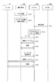
図9Aと図9Bは、接続情報441が有ればペアリングしない動作のシーケンス図である。ユーザは、操作端末100上にてエアコン用アプリケーションを起動しており、エアコン400には、予めルータ21aへの接続情報が格納されている。
エアコン400の制御部410は、電源投入(S20)の直後に、接続情報の有無を判定する。ここでエアコン400の記憶部440には、ルータ21aへの接続情報441が格納されている。よって制御部410は、ルータ21aとの間の一連の接続シーケンスを実行し(S21)、このルータ21aと接続する(S22)。このように、エアコン400の制御部410は、新たなルータへの接続を要しない場合には、ペアリングモードに遷移しない。
その後、ユーザはルータ21aの電源をオフする(S23)。そして、ユーザがルータ21aを撤去してルータ21bに入れ替えて、このルータ21bを起動する。
エアコン400の制御部410は、電源投入(S20)の直後に、接続情報の有無を判定する。ここでエアコン400の記憶部440には、ルータ21aへの接続情報441が格納されている。よって制御部410は、ルータ21aとの間の一連の接続シーケンスを実行し(S21)、このルータ21aと接続する(S22)。このように、エアコン400の制御部410は、新たなルータへの接続を要しない場合には、ペアリングモードに遷移しない。
その後、ユーザはルータ21aの電源をオフする(S23)。そして、ユーザがルータ21aを撤去してルータ21bに入れ替えて、このルータ21bを起動する。
ルータ21bは、SSIDを含むビーコンのバケットを送信する(S30)。これにより操作端末100は、ルータ21bのSSIDを受信する。そして、ユーザは、例えば、操作端末100の設定画面にてルータ21bのSSIDを選択し、更にルータ21bのパスワードを入力する(S31)。これにより操作端末100は、ルータ21bのSSIDとパスワードの組み合わせ、すなわちルータ21bへの接続情報を知ることができる。
ルータ21bへの接続情報に基づき、操作端末100は、ルータ21bとの間の一連の接続シーケンスを実行し(S32)、このルータ21bと接続する(S33)。そして、操作端末100は、ルータ21bへの接続情報を記憶部130に格納する。
ルータ21bへの接続情報に基づき、操作端末100は、ルータ21bとの間の一連の接続シーケンスを実行し(S32)、このルータ21bと接続する(S33)。そして、操作端末100は、ルータ21bへの接続情報を記憶部130に格納する。
図9Bに示した動作は、エアコン400が新たなルータ21に接続するものである。
最初ユーザは、操作端末100にて、エアコン400の接続情報シール460を撮影する(S40)。これにより操作端末100は、エアコン400に接続するための接続情報を取得する。なお、操作端末100が既にエアコン400への接続情報を記憶していた場合、このステップS40の動作を省略してもよい。
最初ユーザは、操作端末100にて、エアコン400の接続情報シール460を撮影する(S40)。これにより操作端末100は、エアコン400に接続するための接続情報を取得する。なお、操作端末100が既にエアコン400への接続情報を記憶していた場合、このステップS40の動作を省略してもよい。
次にエアコン400が電源投入されると(S41)、エアコン400は、ルータ21aへの接続情報に基づいて、ルータ21aへの接続を試み、ルータ21aに係るエラーを監視する。ここでルータ21aは電源オフされて撤去されているので、エアコン400は、ルータ21aに係るエラーを検知する(S42)。これによりエアコン400は、新たなルータとのペアリングを実行するため、アクセスポイントモードに遷移する(S43)。つまりエアコン400の制御部410は、新たなルータ21bへの接続を要する場合にペアリングモードに遷移する。
エアコン400は、自身のSSIDを含むビーコンのバケットを送信する(S44)。操作端末100がエアコン400のSSIDを受信すると、ステップS40で取得したエアコン400への接続情報を用いて、エアコン400との間の一連の接続シーケンスを実行し(S45)、エアコン400との接続を確立する(S46)。
更に操作端末100は、ルータ21bへの接続情報441を、エアコン400に送信する(S47)。エアコン400は、この接続情報441を受信する。
次にエアコン400は、ルータ21bへの接続情報441を用いてルータ21bとの間の一連の接続シーケンスを実行し(S48)、このルータ21との接続を確立する(S49)。
次にエアコン400は、ルータ21bへの接続情報441を用いてルータ21bとの間の一連の接続シーケンスを実行し(S48)、このルータ21との接続を確立する(S49)。
(変形例)
本発明は上記した実施形態に限定されるものではなく、様々な変形例が含まれる。例えば上記した実施形態は、本発明を分かりやすく説明するために詳細に説明したものであり、必ずしも説明した全ての構成を備えるものに限定されるものではない。ある実施形態の構成の一部を他の実施形態の構成に置き換えることが可能であり、ある実施形態の構成に他の実施形態の構成を加えることも可能である。また、各実施形態の構成の一部について、他の構成の追加・削除・置換をすることも可能である。
本発明は上記した実施形態に限定されるものではなく、様々な変形例が含まれる。例えば上記した実施形態は、本発明を分かりやすく説明するために詳細に説明したものであり、必ずしも説明した全ての構成を備えるものに限定されるものではない。ある実施形態の構成の一部を他の実施形態の構成に置き換えることが可能であり、ある実施形態の構成に他の実施形態の構成を加えることも可能である。また、各実施形態の構成の一部について、他の構成の追加・削除・置換をすることも可能である。
上記の各構成、機能、処理部、処理手段などは、それらの一部または全部を、例えば集積回路などのハードウェアで実現してもよい。上記の各構成、機能などは、プロセッサがそれぞれの機能を実現するプログラムを解釈して実行することにより、ソフトウェアで実現してもよい。各機能を実現するプログラム、テーブル、ファイルなどの情報は、メモリ、ハードディスク、SSD(Solid State Drive)などの記録装置、または、フラッシュメモリカード、DVD(Digital Versatile Disk)などの記録媒体に置くことができる。
各実施形態に於いて、制御線や情報線は、説明上必要と考えられるものを示しており、製品上必ずしも全ての制御線や情報線を示しているとは限らない。実際には、殆ど全ての構成が相互に接続されていると考えてもよい。
本発明の変形例として、例えば、次の(a)~(f)のようなものがある。
(a) 本発明はエアコンに限定されず、無線LAN通信機能を備えた任意の電子機器であってもよい。
(b) ルータ検出の監視期間は、120秒に限られない。
(c) 本発明は、ECHONET Lite通信プロトコルに準拠した機器に限られず、他のプロトコルに準拠した機器であってもよい。
(d) ペアリングの方法は、アクセスポイントモードを用いた方法に限られず、例えばWPS(Wi-Fi Protected Setup)方式で接続してもよく、限定されない。
(e) ルータ検出の監視期間における遠隔ランプの点滅と、ペアリングモードにおける遠隔ランプの点滅を異ならせてもよい。
(f) 本発明は、HEMSに限定されず、無線LAN通信機能による遠隔制御を実現するシステムであればよい。
(a) 本発明はエアコンに限定されず、無線LAN通信機能を備えた任意の電子機器であってもよい。
(b) ルータ検出の監視期間は、120秒に限られない。
(c) 本発明は、ECHONET Lite通信プロトコルに準拠した機器に限られず、他のプロトコルに準拠した機器であってもよい。
(d) ペアリングの方法は、アクセスポイントモードを用いた方法に限られず、例えばWPS(Wi-Fi Protected Setup)方式で接続してもよく、限定されない。
(e) ルータ検出の監視期間における遠隔ランプの点滅と、ペアリングモードにおける遠隔ランプの点滅を異ならせてもよい。
(f) 本発明は、HEMSに限定されず、無線LAN通信機能による遠隔制御を実現するシステムであればよい。
1 宅外
3 宅内
10 インターネット
20 ホームゲートウェイ
21 ルータ
100 操作端末
110 通信部
120 制御部
130 記憶部
140 表示部
300 無線LANモジュール (無線LAN通信部)
400 エアコン
410 制御部
420 空調部
430 表示部
431 遠隔ランプ
432 洗浄ランプ
433 クリーンランプ
434 ECOランプ
435 運転ランプ
436 タイマーランプ
437 オートオフランプ
438 みはりランプ
440 記憶部
441 接続情報
450 赤外線受光部
600 専用サーバ
700 遠隔制御システム
800 赤外線リモコン
3 宅内
10 インターネット
20 ホームゲートウェイ
21 ルータ
100 操作端末
110 通信部
120 制御部
130 記憶部
140 表示部
300 無線LANモジュール (無線LAN通信部)
400 エアコン
410 制御部
420 空調部
430 表示部
431 遠隔ランプ
432 洗浄ランプ
433 クリーンランプ
434 ECOランプ
435 運転ランプ
436 タイマーランプ
437 オートオフランプ
438 みはりランプ
440 記憶部
441 接続情報
450 赤外線受光部
600 専用サーバ
700 遠隔制御システム
800 赤外線リモコン
Claims (6)
- 無線通信路を介してルータとペアリングし、ペアリングした当該ルータと通信する無線通信部と、
ペアリングした前記ルータへ接続するための接続情報を記憶する記憶部と、
電源が投入された後、前記記憶部に接続情報が記憶されていなかったならば、所望のルータと接続するペアリングモードに遷移し、前記記憶部に接続情報が記憶されていたならば、前記ペアリングモードに遷移しない制御部と、
を備えることを特徴とする空気調和機。 - 前記制御部は、電源が投入された後、前記記憶部に前記接続情報が記憶されていたならば、前記接続情報に係る前記ルータを監視する監視モードに遷移する、
ことを特徴とする請求項1に記載の空気調和機。 - 前記制御部は、前記監視モードにおいて、所定時間内に前記接続情報に係る前記ルータとのエラーを検出しなかったならば、無線通信できる使用可能モードに遷移する、
ことを特徴とする請求項2に記載の空気調和機。 - 前記制御部は、前記監視モードにおいて、前記所定時間内に前記接続情報に係る前記ルータとのエラーを検出したならば、前記ペアリングモードに遷移する、
ことを特徴とする請求項3に記載の空気調和機。 - 無線通信部を備えたコンピュータに
無線通信路を介してルータとペアリングする工程、
ペアリングした前記ルータと通信する工程、
何れかのルータとペアリングしていたか否かを、新たに電源が投入された際に判定する工程、
何れかのルータとペアリングしていたならば、所望のルータと接続するペアリングモードに遷移せず、ルータとペアリングしていなかったならば、前記ペアリングモードに遷移する工程、
を実行させるための空気調和機の通信制御プログラム。 - 無線通信部が無線通信路を介してルータとペアリングするステップと、
ペアリングした当該ルータと通信するステップと、
制御部が、何れかのルータとペアリングしていたか否かを、新たに電源が投入された際に判定するステップと、
何れかのルータとペアリングしていたならば、所望のルータと接続するペアリングモードに遷移せず、ルータとペアリングしていなかったならば、前記ペアリングモードに遷移するステップと、
を実行することを特徴とする無線通信制御方法。
Priority Applications (2)
| Application Number | Priority Date | Filing Date | Title |
|---|---|---|---|
| JP2020538871A JPWO2021181703A1 (ja) | 2020-03-13 | 2020-03-13 | |
| PCT/JP2020/011273 WO2021181703A1 (ja) | 2020-03-13 | 2020-03-13 | 空気調和機、空気調和機の通信制御プログラム、および、無線通信方法 |
Applications Claiming Priority (1)
| Application Number | Priority Date | Filing Date | Title |
|---|---|---|---|
| PCT/JP2020/011273 WO2021181703A1 (ja) | 2020-03-13 | 2020-03-13 | 空気調和機、空気調和機の通信制御プログラム、および、無線通信方法 |
Publications (1)
| Publication Number | Publication Date |
|---|---|
| WO2021181703A1 true WO2021181703A1 (ja) | 2021-09-16 |
Family
ID=77671488
Family Applications (1)
| Application Number | Title | Priority Date | Filing Date |
|---|---|---|---|
| PCT/JP2020/011273 Ceased WO2021181703A1 (ja) | 2020-03-13 | 2020-03-13 | 空気調和機、空気調和機の通信制御プログラム、および、無線通信方法 |
Country Status (2)
| Country | Link |
|---|---|
| JP (1) | JPWO2021181703A1 (ja) |
| WO (1) | WO2021181703A1 (ja) |
Cited By (1)
| Publication number | Priority date | Publication date | Assignee | Title |
|---|---|---|---|---|
| CN116428694A (zh) * | 2023-03-13 | 2023-07-14 | 青岛海信日立空调系统有限公司 | 一种集控系统和集控方法 |
Citations (5)
| Publication number | Priority date | Publication date | Assignee | Title |
|---|---|---|---|---|
| JP2010278781A (ja) * | 2009-05-28 | 2010-12-09 | Sharp Corp | 通信装置、中継装置、通信システム、通信装置の制御方法、プログラム、及び記録媒体 |
| JP2012530392A (ja) * | 2009-06-11 | 2012-11-29 | クゥアルコム・インコーポレイテッド | ブルームフィルタベースのデバイスの発見 |
| JP2018125849A (ja) * | 2017-01-31 | 2018-08-09 | グリブ カンパニー リミテッドGrib Co.,Ltd | IoTゲートウェイおよびその動作方法 |
| KR20180110686A (ko) * | 2017-03-27 | 2018-10-11 | 주식회사 비즈모델라인 | 차량 거치형 공기청정장치 |
| WO2018220898A1 (ja) * | 2017-06-02 | 2018-12-06 | シャープ株式会社 | 通信制御システム、空気調和機 |
Family Cites Families (3)
| Publication number | Priority date | Publication date | Assignee | Title |
|---|---|---|---|---|
| JP5242528B2 (ja) * | 2009-09-18 | 2013-07-24 | 東芝キヤリア株式会社 | 遠隔制御装置 |
| JP6498419B2 (ja) * | 2014-11-21 | 2019-04-10 | ローム株式会社 | 電力線通信装置 |
| JP7052641B2 (ja) * | 2018-08-27 | 2022-04-12 | 村田機械株式会社 | 無線通信システム及び無線通信方法 |
-
2020
- 2020-03-13 WO PCT/JP2020/011273 patent/WO2021181703A1/ja not_active Ceased
- 2020-03-13 JP JP2020538871A patent/JPWO2021181703A1/ja active Pending
Patent Citations (5)
| Publication number | Priority date | Publication date | Assignee | Title |
|---|---|---|---|---|
| JP2010278781A (ja) * | 2009-05-28 | 2010-12-09 | Sharp Corp | 通信装置、中継装置、通信システム、通信装置の制御方法、プログラム、及び記録媒体 |
| JP2012530392A (ja) * | 2009-06-11 | 2012-11-29 | クゥアルコム・インコーポレイテッド | ブルームフィルタベースのデバイスの発見 |
| JP2018125849A (ja) * | 2017-01-31 | 2018-08-09 | グリブ カンパニー リミテッドGrib Co.,Ltd | IoTゲートウェイおよびその動作方法 |
| KR20180110686A (ko) * | 2017-03-27 | 2018-10-11 | 주식회사 비즈모델라인 | 차량 거치형 공기청정장치 |
| WO2018220898A1 (ja) * | 2017-06-02 | 2018-12-06 | シャープ株式会社 | 通信制御システム、空気調和機 |
Cited By (1)
| Publication number | Priority date | Publication date | Assignee | Title |
|---|---|---|---|---|
| CN116428694A (zh) * | 2023-03-13 | 2023-07-14 | 青岛海信日立空调系统有限公司 | 一种集控系统和集控方法 |
Also Published As
| Publication number | Publication date |
|---|---|
| JPWO2021181703A1 (ja) | 2021-09-16 |
Similar Documents
| Publication | Publication Date | Title |
|---|---|---|
| CN112198819B (zh) | 负载控制系统及设备 | |
| EP1699028B1 (en) | Wireless alarm system with remote alarm receipt | |
| KR102137049B1 (ko) | 조명 장치, 조명 장치 시스템 및 조명장치의 등록 방법 | |
| CN104582167B (zh) | 照明设备、智能终端、照明设备组网系统及方法 | |
| CN110651483B (zh) | 通信控制系统、空调机 | |
| EP3075206B1 (en) | Zigbee light link network commissioning | |
| JP2010514320A (ja) | 無線ネットワークの装置をリセットする方法及びシステム並びに無線ネットワーク装置 | |
| JP2006129098A (ja) | 遠隔操作装置および遠隔制御システム | |
| CN105137774A (zh) | 一种智能家电控制方法、装置及移动终端 | |
| JP2005328295A (ja) | 無線通信システム | |
| CN106713760A (zh) | 终端、led灯的控制显示系统和方法 | |
| JP6469770B2 (ja) | 遠隔操作システムにおける登録支援システム | |
| TWI666909B (zh) | 照明器具或照明控制裝置之控制方法、程式及終端裝置 | |
| KR101377065B1 (ko) | 모바일 기기를 이용한 홈오토메이션 시스템 | |
| JP2011151700A (ja) | 無線センサーネットワークシステム | |
| AU2016434810B2 (en) | Device control system | |
| US11856675B2 (en) | Providing a notification for a lighting device without user-specified power-switch behavior | |
| JP6570616B2 (ja) | 遠隔操作システム、コントローラ、および、プログラム | |
| JP6640942B2 (ja) | 遠隔操作システムにおける登録支援システム | |
| AU2021437956B2 (en) | Device control system | |
| KR20130090182A (ko) | 스마트 클라우드를 이용한 다중기기 제어 장치 | |
| CN117948698A (zh) | 一种空调的控制方法及空调器 | |
| JP2025123618A (ja) | 照明制御システム、照明制御方法、プログラムおよび表示方法 | |
| JP2026010303A (ja) | 通信システム、制御端末、制御方法及びプログラム | |
| TWM469687U (zh) | 電子裝置遙控系統 |
Legal Events
| Date | Code | Title | Description |
|---|---|---|---|
| ENP | Entry into the national phase |
Ref document number: 2020538871 Country of ref document: JP Kind code of ref document: A |
|
| 121 | Ep: the epo has been informed by wipo that ep was designated in this application |
Ref document number: 20924636 Country of ref document: EP Kind code of ref document: A1 |
|
| NENP | Non-entry into the national phase |
Ref country code: DE |
|
| 122 | Ep: pct application non-entry in european phase |
Ref document number: 20924636 Country of ref document: EP Kind code of ref document: A1 |