WO2021181671A1 - 光伝送装置及び光伝送方法 - Google Patents
光伝送装置及び光伝送方法 Download PDFInfo
- Publication number
- WO2021181671A1 WO2021181671A1 PCT/JP2020/011167 JP2020011167W WO2021181671A1 WO 2021181671 A1 WO2021181671 A1 WO 2021181671A1 JP 2020011167 W JP2020011167 W JP 2020011167W WO 2021181671 A1 WO2021181671 A1 WO 2021181671A1
- Authority
- WO
- WIPO (PCT)
- Prior art keywords
- unit
- signal
- optical
- wave signal
- combined wave
- Prior art date
- Legal status (The legal status is an assumption and is not a legal conclusion. Google has not performed a legal analysis and makes no representation as to the accuracy of the status listed.)
- Ceased
Links
Images




Classifications
-
- H—ELECTRICITY
- H04—ELECTRIC COMMUNICATION TECHNIQUE
- H04B—TRANSMISSION
- H04B10/00—Transmission systems employing electromagnetic waves other than radio-waves, e.g. infrared, visible or ultraviolet light, or employing corpuscular radiation, e.g. quantum communication
- H04B10/03—Arrangements for fault recovery
- H04B10/032—Arrangements for fault recovery using working and protection systems
-
- H—ELECTRICITY
- H04—ELECTRIC COMMUNICATION TECHNIQUE
- H04B—TRANSMISSION
- H04B10/00—Transmission systems employing electromagnetic waves other than radio-waves, e.g. infrared, visible or ultraviolet light, or employing corpuscular radiation, e.g. quantum communication
- H04B10/50—Transmitters
- H04B10/501—Structural aspects
- H04B10/506—Multiwavelength transmitters
-
- H—ELECTRICITY
- H04—ELECTRIC COMMUNICATION TECHNIQUE
- H04B—TRANSMISSION
- H04B10/00—Transmission systems employing electromagnetic waves other than radio-waves, e.g. infrared, visible or ultraviolet light, or employing corpuscular radiation, e.g. quantum communication
- H04B10/60—Receivers
- H04B10/61—Coherent receivers
- H04B10/614—Coherent receivers comprising one or more polarization beam splitters, e.g. polarization multiplexed [PolMux] X-PSK coherent receivers, polarization diversity heterodyne coherent receivers
-
- H—ELECTRICITY
- H04—ELECTRIC COMMUNICATION TECHNIQUE
- H04J—MULTIPLEX COMMUNICATION
- H04J14/00—Optical multiplex systems
- H04J14/02—Wavelength-division multiplex systems
-
- H—ELECTRICITY
- H04—ELECTRIC COMMUNICATION TECHNIQUE
- H04J—MULTIPLEX COMMUNICATION
- H04J14/00—Optical multiplex systems
- H04J14/02—Wavelength-division multiplex systems
- H04J14/0287—Protection in WDM systems
- H04J14/0293—Optical channel protection
-
- H—ELECTRICITY
- H04—ELECTRIC COMMUNICATION TECHNIQUE
- H04B—TRANSMISSION
- H04B10/00—Transmission systems employing electromagnetic waves other than radio-waves, e.g. infrared, visible or ultraviolet light, or employing corpuscular radiation, e.g. quantum communication
- H04B10/25—Arrangements specific to fibre transmission
- H04B10/2575—Radio-over-fibre, e.g. radio frequency signal modulated onto an optical carrier
- H04B10/25751—Optical arrangements for CATV or video distribution
-
- H—ELECTRICITY
- H04—ELECTRIC COMMUNICATION TECHNIQUE
- H04B—TRANSMISSION
- H04B10/00—Transmission systems employing electromagnetic waves other than radio-waves, e.g. infrared, visible or ultraviolet light, or employing corpuscular radiation, e.g. quantum communication
- H04B10/40—Transceivers
-
- H—ELECTRICITY
- H04—ELECTRIC COMMUNICATION TECHNIQUE
- H04B—TRANSMISSION
- H04B10/00—Transmission systems employing electromagnetic waves other than radio-waves, e.g. infrared, visible or ultraviolet light, or employing corpuscular radiation, e.g. quantum communication
- H04B10/50—Transmitters
-
- H—ELECTRICITY
- H04—ELECTRIC COMMUNICATION TECHNIQUE
- H04B—TRANSMISSION
- H04B10/00—Transmission systems employing electromagnetic waves other than radio-waves, e.g. infrared, visible or ultraviolet light, or employing corpuscular radiation, e.g. quantum communication
- H04B10/60—Receivers
Definitions
- the present invention relates to an optical transmission device and an optical transmission method.
- FIG. 7 is a diagram showing a configuration example of a video communication network system 900 using the prior art.
- an FM (Frequency Modulation) batch conversion method is used (see Non-Patent Document 1).
- the video communication network system 900 is installed in, for example, a transmission device 910, a transmission device 911, one or more transmission devices 920, one or more transmission devices 921, a WDM filter 930, and each subscriber's home or the like. It has a receiving device 950 and a receiving device 951.
- the receiving device 950 and the receiving device 951 are shown one by one, but the number of the subscriber's house and the number of the receiving device 950 and the receiving device 951 in the subscriber's house are arbitrary.
- the WDM filter 930 and the receiving device 950 are connected via an access network 940.
- the access network 940 performs wavelength division multiplexing transmission.
- the transmission device 910 inputs video signals of terrestrial digital broadcasting, BS (Broadcasting Satellites) broadcasting and CS (Communication Satellites) broadcasting distributed from artificial satellites to the ground using right-handed circular polarization.
- this video signal is also referred to as a terrestrial digital / BSCS right-handed video signal.
- the transmission device 911 inputs the video signals of BS broadcasting and CS broadcasting distributed from the artificial satellite to the ground using left-handed circularly polarized waves. These are video signals for new 4K / 8K satellite broadcasting.
- this video signal is also referred to as a BSCS left-handed video signal.
- Each of the transmission device 910 and the transmission device 911 collectively converts the input multi-channel video signal into a wide band FM signal, and then converts the input multi-channel video signal into an optical signal and outputs the signal.
- the optical signal SG90 having a wavelength ⁇ 1 (for example, ⁇ 1 is 1558 nm) output by the transmission device 910 is relay-transmitted by the transmission device 920 and then input to the WDM filter 930.
- the optical signal SG91 having a wavelength ⁇ 2 (for example, ⁇ 2 is 1552 nm) output by the transmission device 910 is relay-transmitted by the transmission device 920 and then input to the WDM filter 930.
- ⁇ 2 1558 nm is used.
- the WDM filter 930 combines the optical signal SG90 for video relayed by the transmission device 920, the optical signal SG91 for video relayed by the transmission device 921, and the optical signal for communication input from a transmission device (not shown).
- the waved combined wave signal SG92 is output to the access network 940.
- the combined wave signal SG92 transmitted through the access network 940 is demultiplexed, the receiving device 950 receives the combined wave signal SG93 for the image of the wavelength ⁇ 1, and the receiving device 951 receives the combined wave signal SG94 for the image of the wavelength ⁇ 2. ..
- the receiving device 950 and the receiving device 951 are cut by a filter except for the wavelength band corresponding to the own device.
- ITU-T J.185 Transmission equipment for transferring multi-channel television signals over optical access networks by frequency modulation conversion
- the terrestrial digital / BSCS right-handed video signal and the BSCS left-handed video signal are relayed by different systems. Therefore, relay transmission equipment is required for each of the terrestrial digital / BSCS right-handed video signal and the BSCS left-handed video signal. Therefore, it is conceivable to combine the terrestrial digital / BSCS right-handed video signal and the BSCS left-handed video signal, which use different wavelengths, and transmit them in one system. However, some of the combined video signals are deteriorated, and the video being viewed by the viewer may be interrupted.
- an object of the present invention is to provide an optical transmission device and an optical transmission method capable of transmitting a combined wave signal in which optical signals of different wavelengths are combined with high quality.
- One aspect of the present invention is an optical input for inputting a first combined wave signal in which a plurality of optical signals having different wavelengths are combined and a second combined wave signal in which a plurality of the optical signals having different wavelengths are combined.
- a measuring unit that measures the quality of each of the plurality of optical signals obtained by demultiplexing the second combined wave signal, and the first combined wave signal and the second combined wave signal based on the measurement results by the measuring unit.
- It is an optical transmission device including a switching unit for switching which of the wave signals is output to the subsequent stage.
- One aspect of the present invention is an input step of inputting a first combined wave signal in which a plurality of optical signals having different wavelengths are combined and a second combined wave signal in which a plurality of the optical signals having different wavelengths are combined.
- the demultiplexing step of demultiplexing the first combined signal and the second combined signal according to the wavelength, the quality of each of the plurality of optical signals obtained by demultiplexing the first combined signal, and the above.
- the first combined wave signal and the second combined wave are based on a measurement step for measuring the quality of each of a plurality of optical signals obtained by demultiplexing the second combined wave signal and the result of the measurement by the measurement step.
- This is an optical transmission method having a switching unit step for switching which of the signals is output to the subsequent stage.
- the redundant optical transmission system of the embodiment has a redundant configuration in which a transmission signal is transmitted by a redundant transmission line.
- the transmission signal is a combined wave signal in which optical signals of a plurality of wavelength bands are combined.
- the redundant optical transmission system measures the signal quality in each wavelength band before the wavefront of the transmission signal and holds it internally or externally in advance. Signal quality is represented, for example, by level or level difference.
- the signal selection device of the redundant optical transmission system inputs two transmission signals transmitted through each of the duplicated transmission lines, and demultiplexes each transmission signal into optical signals for each wavelength.
- the signal selection device detects the presence or absence of quality deterioration based on the stored information for each optical signal obtained by demultiplexing.
- the switching unit of the signal selection device selects and outputs the other transmission signal in which the quality deterioration is not detected. This makes it possible to more accurately detect an abnormal state even in signal transmission in a combined wave state and switch the transmission signal to be output in the subsequent stage.
- the redundant optical transmission system is a video communication network system for transmitting a video signal.
- FIG. 1 is a diagram showing a configuration example of the video communication network system 100 according to the first embodiment.
- the video communication network system 100 is installed in a transmission device 110, a transmission device 111, a WDM filter 120, one or more transmission devices 130, a transmission device 140, a WDM filter 150, and each subscriber's home or the like. It has a receiving device 170 and a receiving device 171.
- the receiving device 170 and the receiving device 171 are shown one by one, but the number of the subscriber's house and the number of the receiving device 170 and the receiving device 171 in the subscriber's house are arbitrary.
- the WDM filter 150, the receiving device 170, and the receiving device 171 are connected via the access network 160.
- the access network 160 performs wavelength division multiplexing transmission.
- the transmitting device 110, the transmitting device 111, the access network 160, the receiving device 170, and the receiving device 171 are the same as the transmitting device 910, the transmitting device 911, the access network 940, the receiving device 950, and the receiving device 950 shown in FIG.
- the transmission device 110 inputs video signals of terrestrial digital broadcasting, BS broadcasting and CS broadcasting distributed from an artificial satellite to the ground using right-handed circular polarization, and has a wide band. Batch conversion to FM signals.
- the transmission device 110 converts the batch-converted FM signal into an optical signal SG10 having a wavelength of ⁇ 1 and inputs the FM signal to the WDM filter 120.
- the transmission device 111 inputs the video signals of BS broadcasting and CS broadcasting distributed from the artificial satellite to the ground using left-handed circularly polarized waves, and collectively converts them into wideband FM signals. do.
- the transmission device 111 converts the batch-converted FM signal into an optical signal SG11 having a wavelength of ⁇ 2, and inputs the FM signal to the WDM filter 120.
- the WDM filter 120 combines the optical signal SG10 having a wavelength ⁇ 1 input from the transmitting device 110 and the optical signal SG11 having a wavelength ⁇ 2 input from the transmitting device 111, and outputs the combined wave signal SG12.
- the combined wave signal SG12 output by the WDM filter 120 is relay-transmitted by one or more transmission devices 130 and the transmission device 140, and then input to the WDM filter 150.
- the WDM filter 150 combines the combined wave signal SG12 input from the transmission device 140 and the optical signal for communication input from the transmission device (not shown), and outputs the combined wave signal SG13 to the access network 160.
- the combined wave signal SG13 transmitted through the access network 160 is demultiplexed, the receiving device 170 receives the optical signal SG14 for the image of the wavelength ⁇ 1, and the receiving device 171 receives the optical signal SG15 for the image of the wavelength ⁇ 2.
- the two-wavelength transmission from the WDM filter 120 to the WDM filter 150 is duplicated.
- the configuration of the redundant two-wavelength transmission applied to the video communication network system 100 will be described with reference to FIG.
- FIG. 2 is a diagram showing the configuration of the optical transmission system 200 of the present embodiment.
- the optical transmission system 200 includes a head end 210, a head end 211, an optical transmission unit 220, an optical transmission unit 221, an optical transmission unit 230, an optical transmission unit 231 and a combiner unit 240, and a combiner unit 241.
- the 0 system is an operational system
- the 1 system is a backup system.
- the head end 210, the optical transmission unit 220, and the optical transmission unit 230 are operational systems.
- the head end 211, the optical transmission unit 221 and the optical transmission unit 231 are preliminary systems.
- the head end 210, the optical transmission unit 220, and the optical transmission unit 221 correspond to the transmission device 110 shown in FIG. 1, and the head end 211, the optical transmission unit 230, and the optical transmission unit 231 are shown in FIG. Corresponds to the transmitter 111 shown.
- the combiner 240 and the combiner 241 correspond to the WDM filter 120 shown in FIG.
- the relay amplification unit 250 may be the transmission device 130 shown in FIG. 1 or an amplification device connected to the transmission device 130.
- the signal selection device 260 corresponds to the transmission device 140 shown in FIG.
- the amplification unit 270 is connected to the front stage of the WDM filter 150 shown in FIG. 1, and the distribution unit 280 is connected to the rear stage of the WDM filter 150 shown in FIG.
- the optical receiver 290 corresponds to the receiver 170 and the receiver 171 shown in FIG.
- the headend 210 receives video signals of terrestrial digital broadcasting transmitted from a broadcasting station and BS broadcasting and CS broadcasting distributed from an artificial satellite to the ground using right-handed circularly polarized waves by radio waves.
- the wavelength of the video signal is different for each channel.
- the head end 210 converts the video signal of each channel into an electric signal and sends it to the optical transmission unit 220 and the optical transmission unit 221.
- the optical transmission unit 220 and the optical transmission unit 221 convert the received electric signal of each channel into an optical signal SG10 having a wavelength of ⁇ 1. FM batch conversion is used for the conversion.
- the optical transmission unit 220 outputs the converted optical signal SG10 to the combiner unit 240, and the optical transmission unit 221 outputs the converted optical signal SG10 to the combiner unit 241.
- the headend 211 receives the video signal of the new 4K / 8K satellite broadcast transmitted from the broadcasting station by radio waves.
- the wavelength of the video signal is different for each channel.
- the head end 211 converts the video signal of each channel into an electric signal and sends it to the optical transmission unit 230 and the optical transmission unit 231.
- the optical transmission unit 230 and the optical transmission unit 231 convert the received electric signal of each channel into an optical signal SG11 having a wavelength of ⁇ 2. FM batch conversion is used for the conversion.
- the optical transmission unit 230 outputs the converted optical signal SG11 to the combiner unit 240, and the optical transmission unit 231 outputs the converted optical signal SG11 to the combiner unit 241.
- the combiner 240 combines the optical signal SG10 having a wavelength ⁇ 1 received from the optical transmission unit 220 and the optical signal SG11 having a wavelength ⁇ 2 received from the optical transmitter 230, and transmits the 0-system combiner signal SG20 to the transmission line. Output to 245.
- the combined wave signal SG20 of the optical signal is amplified by one or more relay amplification units 250 provided in the transmission line 245 and relayed to the subsequent stage.
- the combiner 241 combines the optical signal SG10 having a wavelength ⁇ 1 received from the optical transmission unit 221 and the optical signal SG11 having a wavelength ⁇ 2 received from the optical transmission unit 231, and transmits the combined wave signal SG21 of one system. Output to 246.
- the combined wave signal SG21 of the optical signal is amplified by one or more relay amplification units 251 provided in the transmission line 246 and relayed to the subsequent stage.
- the signal selection device 260 is an example of an optical transmission device.
- the signal selection device 260 includes a relay amplification unit 261, a relay amplification unit 262, and a signal selection unit 263.
- the relay amplification unit 261 amplifies the 0-system combined wave signal SG20 transmitted through the transmission line 245 and outputs it to the signal selection unit 263.
- the relay amplification unit 262 amplifies the combined wave signal SG21 of the 1 system transmitted through the transmission line 246 and outputs it to the signal selection unit 263.
- the signal selection unit 263 selects either the combined wave signal SG20 or the combined wave signal SG21 and outputs the combined wave signal SG22 to the subsequent stage.
- the amplification unit 270 amplifies the combined wave signal SG22 output by the signal selection device 260 and outputs it to the access network.
- the distribution unit 280 distributes the combined wave signal SG22 received via the access network.
- the optical receiving unit 290 receives the combined wave signal SG22 distributed by the distributing unit 280, and receives the optical signal SG10 having a wavelength ⁇ 1 or the optical signal SG11 having a wavelength ⁇ 2 that are combined with the combined wave signal SG22.
- FIG. 8 is a diagram showing a configuration example of the signal selection unit 980 according to the prior art.
- the signal selection unit 980 includes an optical input unit 981, an optical input unit 982, a detection unit 983, a detection unit 984, a switching unit 985, and an optical output unit 986.
- the optical input unit 981 inputs the 0-system combined wave signal SG20
- the optical input unit 982 inputs the 1-system combined wave signal SG21.
- the detection unit 983 outputs the 0-system combined wave signal SG20 input by the optical input unit 981 to the switching unit 985, and requests switching to the 1-system when the level drop of the 0-system combined wave signal SG20 is detected.
- the process of outputting the signal SG80 to the switching unit 985 is performed.
- the detection unit 983 outputs the 1-system combined wave signal SG21 input by the optical input unit 982 to the switching unit 985, and requests to switch to the 0-system when the level drop of the 1-system combined wave signal SG21 is detected.
- the process of outputting the signal SG81 to the switching unit 985 is performed.
- the switching request signal SG80 and the switching request signal SG81 are control signals.
- the switching unit 985 When the switching unit 985 receives the switching request signal SG80 for the 1st system, the switching unit 985 outputs the combined wave signal SG21 of the 1st system to the optical output unit 986.
- the switching unit 985 receives the switching request signal SG81 for the 0 system, the switching unit 985 outputs the combined wave signal SG20 of the 0 system to the optical output unit 986.
- the optical output unit 986 outputs the 0-system combined wave signal SG20 or the 1-system combined wave signal SG21 output by the switching unit 985 as the combined wave signal SG22 in the subsequent stage.
- the signal selection unit 980 may implement a level adjustment function, but it is omitted in FIG.
- the combined wave signal SG20 and the combined wave signal SG21 are signals in which the optical signal SG10 having a wavelength ⁇ 1 and the optical signal SG11 having a wavelength ⁇ 2 are combined.
- the detection unit 983 detects the level drop of the wave signal SG20, and the detection unit 984 detects the level drop of the wave signal SG21.
- neither the detection unit 983 nor the detection unit 984 can detect which of the optical signal SG10 having the wavelength ⁇ 1 and the optical signal SG11 having the wavelength ⁇ 2 is abnormal.
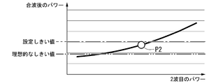
- the ideal threshold value is a value based on the state when there is no power deterioration in each of the two optical signals.
- the set threshold value is lower than the ideal threshold value and the power after the combined wave is the value of P1 exceeding the set threshold value, the light of the second wave. It may not switch even if the signal power is low.
- the set threshold value is higher than the ideal threshold value, there is a problem with the power of the second wave when the power after the combined wave is a value of P2 smaller than the set threshold value. Switching may be performed even if there is no.
- the signal selection unit of the present embodiment demultiplexes the combined wave signal and returns it to the signal of the original wavelength, and then measures the level of the optical signal and detects the level decrease in order to determine the switching. Since the signal selection unit measures the level and detects the level drop for each wavelength, it detects the deterioration of the signal of each wavelength more accurately than the level measurement and the detection of the level drop as the combined wave signal. can do. Therefore, it is possible to improve the determination accuracy of the switching process.
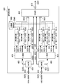
- FIG. 3 is a diagram showing a detailed configuration of the signal selection unit 300 of the present embodiment.
- the signal selection unit 300 shown in FIG. 3 is used as the signal selection unit 263 included in the signal selection device 260 shown in FIG.
- the signal selection unit 300 includes an optical input unit 310, an optical input unit 311, a demultiplexing unit 320, a demultiplexing unit 321 and a storage unit 330, and measurement detection units 340-1 to 340-N (N is 2 or more). ), Measurement detection units 341-1 to 341-N (N is an integer of 2 or more), a combine unit 350, a combine unit 351, a switching unit 360, and an optical output unit 370.
- the optical input unit 310 inputs the 0-system combined wave signal SG20, and the optical input unit 311 inputs the 1-system combined wave signal SG21.
- the demultiplexing unit 320 demultiplexes the 0-system combined wave signal SG20 into N optical signals SG30-1 to SG30-N having different wavelengths.
- the demultiplexing unit 320 outputs an optical signal SG30-n (n is an integer of 1 or more and N or less) to the measurement detection unit 340-n.
- the demultiplexing unit 321 demultiplexes the combined wave signal SG21 of the 1 system into N optical signals SG31-1 to SG31-N having different wavelengths.
- the demultiplexing unit 321 outputs an optical signal SG31-n (n is an integer of 1 or more and N or less) to the measurement detection unit 341-n.
- the storage unit 330 stores the setting table in advance.
- the setting table shows the threshold value of the optical signal level of each wavelength required for detection for switching.
- the optical signal level thresholds for each of the N wavelengths are described as optical signal level thresholds P (1) to P (N).
- the measurement detection units 340-1 to 340-N and 341-1 to 341-N read information from the storage unit 330 using the control signal SG40.
- the measurement detection unit 340-n has a measurement unit 3401, a detection unit 3402, and an instruction unit 3403, respectively.
- the measuring unit 3401 measures the optical signal level M0 (n) of the input optical signal SG30-n, and outputs the measured optical signal SG30-n to the combiner 350.
- the detection unit 3402 reads out the optical signal level threshold value P (n) stored in the storage unit 330 and compares it with the optical signal level M0 (n).
- the detection unit 3402 detects quality deterioration when M0 (n) ⁇ P (n) or M0 (n) ⁇ P (n).
- the instruction unit 3403 outputs the switching instruction SG50 to the 1 system to the switching unit 360.
- the switching instruction SG50 is a control signal.
- the measurement detection unit 341-n has a measurement unit 3411, a detection unit 3412, and an instruction unit 3413, respectively.
- the measuring unit 3411 measures the optical signal level M1 (n) of the input optical signal SG31-n, and outputs the measured optical signal SG31-n to the combine unit 351.
- the detection unit 3412 reads out the optical signal level threshold value P (n) stored in the storage unit 330 and compares it with the optical signal level M1 (n).
- the detection unit 3412 detects quality deterioration when M1 (n) ⁇ P (n) or M1 (n) ⁇ P (n).
- the instruction unit 3413 outputs the switching instruction SG51 to the 0 system to the switching unit 360.
- the switching instruction SG51 is a control signal.
- the combiner 350 inputs optical signals SG30-1 to SG30-N from each of the measurement detection units 340-1 to 340-N.
- the combiner 350 outputs the combiner signal SG20, which is a combination of the optical signals SG30-1 to SG30-N, to the switching unit 360.
- the combined wave unit 351 inputs optical signals SG31-1 to SG31-N from each of the measurement detection units 341-1 to 341-n.
- the combiner section 351 outputs the combiner signal SG21, which is a combination of the optical signals SG31-1 to SG31-N, to the switching unit 360.
- the switching unit 360 When the switching unit 360 receives the switching instruction, it switches whether to output the combined wave signal SG20 or the combined wave signal SG21.
- the switching unit 360 receives the switching instruction SG50 from at least one of the measurement detection units 340-1 to 340-N to one system, the switching unit 360 selects the combined wave signal SG21 and outputs it to the optical output unit 370.
- the switching unit 360 receives the switching instruction SG51 from at least one of the measurement detection units 341-1 to 341-N to the 0 system, the switching unit 360 selects the combined wave signal SG20 and outputs it to the optical output unit 370.
- the optical output unit 370 outputs the combined wave signal SG20 or the combined wave signal SG21 output from the switching unit 360 as the combined wave signal SG22 in the subsequent stage.
- the storage unit 330 may be provided in a device outside the signal selection device 260, or may be provided outside the signal selection unit 300 in the signal selection device 260. Further, a part of the functions of the measurement detection units 340-1 to 340-N and 341-1 to 341-N and the storage unit 330 may be provided by an external device of the signal selection unit 300 or the signal selection device 260. ..
- an external control device that monitors and controls the video communication network system 100 or the optical transmission system 200 has some of the functions of the measurement detection units 340-1 to 340-N and 341-1 to 341-N. You may.
- the control device has a detection unit 3402 and an instruction unit 3403 of the measurement detection units 340-1 to 340-N, and a detection unit 3412 and an instruction unit 3413 of the measurement detection units 341-1 to 341-N. May be good.
- the measurement detection unit 340-n measures the optical signal level M0 (n) of the optical signal SG30-n and notifies the control device, and the measurement detection unit 341-n measures the optical signal level M1 (optical signal level M1) of the optical signal SG31-n. n) is measured and notified to the control device.
- the control device When M0 (n) ⁇ P (n) or M0 (n) ⁇ P (n), the control device outputs a switching instruction SG50 to the 1 system to the switching unit 360, and M1 (n) ⁇ P (n). ) Or M1 (n) ⁇ P (n), the switching unit 360 outputs the switching instruction SG51 to the 0 system.
- the signal selection unit 300 uses the signal selection unit 300 to combine waves between the combining unit 350 and the switching unit 360 and between the combining unit 351 and the switching unit 360.
- a level adjustment unit (AMP) 380 that amplifies the signal may be provided.
- the signal selection device of the first embodiment demultiplexes the main signal output to the subsequent stage, performs level measurement, and then combines the signals. Since the signal selection device of the present embodiment branches the input combined signal and demultiplexes the branched combined signal to measure the level, the main signal is not combined and demultiplexed.
- the present embodiment will be described with a focus on differences from the first embodiment.
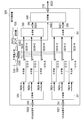
- FIG. 4 is a diagram showing a detailed configuration of the signal selection unit 400 of the present embodiment.
- the signal selection unit 400 shown in FIG. 4 is used as the signal selection unit 263 included in the signal selection device 260 shown in FIG.
- the signal selection unit 400 includes an optical input unit 410, an optical input unit 411, a branch unit 420, a branch unit 421, a demultiplexing unit 430, a demultiplexing unit 431, a storage unit 440, and a measurement detection unit 450-. It has 1 to 450-N (N is an integer of 2 or more), measurement detection units 451-1 to 451-N, a switching unit 460, and an optical output unit 470.
- the optical input unit 410 inputs the 0-series combined wave signal SG20 and outputs it to the branch unit 420.
- the optical input unit 411 inputs the combined wave signal SG21 of the 1 system and outputs it to the branch unit 421.
- the branching unit 420 branches the combined wave signal SG20 input from the optical input unit 410.
- the branching unit 420 outputs the branched combined wave signal SG20 to the demultiplexing unit 430, and outputs the combined wave signal SG20 of the main signal to the switching unit 460.
- the branching unit 421 branches the combined wave signal SG21 input from the optical input unit 411.
- the branching unit 421 outputs the branched wave signal SG21 to the demultiplexing unit 431, and outputs the main signal wave signal SG21 to the switching unit 460.
- the demultiplexing unit 430 demultiplexes the 0-series combined wave signal SG20 into optical signals SG30-1 to SG30-N having N wavelengths.
- the demultiplexing unit 430 outputs an optical signal SG30-n (n is an integer of 1 or more and N or less) to the measurement detection unit 450-n.
- the demultiplexing unit 431 demultiplexes the combined wave signal SG21 of the 1 system into optical signals SG31-1 to SG31-N having N wavelengths.
- the demultiplexing unit 431 outputs an optical signal SG31-n (n is an integer of 1 or more and N or less) to the measurement detection unit 451-n.
- the storage unit 440 stores the same setting table as the storage unit 330 of the first embodiment shown in FIG.
- the measurement detection units 450-1 to 450-N and 451-1 to 451-N read information from the storage unit 440 using the control signal SG40.
- the measurement detection unit 450-n has a measurement unit 4501, a detection unit 4502, and an indicator unit 4503, respectively.
- the measuring unit 4501 measures the optical signal level M0 (n) of the input optical signal SG30-n.
- the detection unit 4502 reads out the optical signal level threshold value P (n) stored in the storage unit 440 and compares it with the optical signal level M0 (n).
- the detection unit 4502 detects quality deterioration when M0 (n) ⁇ P (n) or M0 (n) ⁇ P (n).
- the instruction unit 4503 outputs the switching instruction SG50 to the 1 system to the switching unit 460.
- the measurement detection unit 451-n has a measurement unit 4511, a detection unit 4512, and an instruction unit 4513, respectively.
- the measuring unit 4511 measures the optical signal level M1 (n) of the input optical signal SG31-n.
- the detection unit 4512 reads out the optical signal level threshold value P (n) stored in the storage unit 440 and compares it with the optical signal level M1 (n).
- the detection unit 4512 detects quality deterioration when M1 (n) ⁇ P (n) or M1 (n) ⁇ P (n).
- the instruction unit 4513 outputs the switching instruction SG51 to the 0 system to the switching unit 460.
- the switching unit 460 When the switching unit 460 receives the switching instruction SG50 from at least one of the measurement detection units 450-1 to 450-N to the first system, the switching unit 460 selects the combined wave signal SG21 input from the branching unit 421 and sends the optical output unit 470 to the optical output unit 470. Output.
- the switching unit 460 receives the switching instruction SG51 from at least one of the measurement detection units 451-1 to 451-N to the 0 system, the switching unit 460 selects the combined wave signal SG20 input from the branch unit 420 and sends the optical output unit 470 to the optical output unit 470. Output.
- the optical output unit 470 outputs the combined wave signal SG20 or the combined wave signal SG21 output from the switching unit 460 as the combined wave signal SG22 in the subsequent stage.
- the storage unit 440 may be provided in a device outside the signal selection device 260, or may be provided outside the signal selection unit 400 in the signal selection device 260. Further, a device outside the signal selection unit 400 or the signal selection device 260 may have a part of the functions of the measurement detection units 450-1 to 450-N and 451-1 to 451-N and the storage unit 440. ..
- an external control device that monitors and controls the video communication network system 100 or the optical transmission system 200 has some of the functions of the measurement detection units 450-1 to 450-N and 451-1 to 451-N. You may.
- the control device has a detection unit 4502 and an instruction unit 4503 of the measurement detection units 450-1 to 450-N, and a detection unit 4512 and an instruction unit 4513 of the measurement detection units 451-1 to 451-N. May be good.
- the measurement detection unit 450-n measures the optical signal level M0 (n) of the optical signal SG30-n and notifies the control device, and the measurement detection unit 451-n measures the optical signal level M1 (optical signal level M1) of the optical signal SG31-n. n) is measured and notified to the control device.
- the control device When M0 (n) ⁇ P (n) or M0 (n) ⁇ P (n), the control device outputs a switching instruction SG50 to the 1 system to the switching unit 460, and M1 (n) ⁇ P (n). ) Or M1 (n) ⁇ P (n), the switching unit 460 is output with the switching instruction SG51 to the 0 system.
- the signal selection unit 400 is used between the branching unit 420 and the demultiplexing unit 430, between the branching unit 420 and the switching unit 460, and between the branching unit 421 and the demultiplexing unit.
- a level adjustment unit (AMP) 480 that amplifies the combined wave signal may be provided between the branch unit 421 and the switching unit 460 between the 431 and the branch unit 421.
- this embodiment is slightly more complicated than that of the first embodiment, since the main signal is not demultiplexed and combined, the quality deterioration of the main signal is suppressed as compared with the first embodiment. Is possible.
- the signal selection device of the first embodiment demultiplexes the combined wave signals of the 0 system and the 1 system, compares the optical signal level of each wavelength obtained by the demultiplexing with the threshold value, and deteriorates the optical signal. It was detected.
- the signal selection device of the present embodiment detects deterioration of an optical signal based on an optical signal level difference between adjacent wavelengths.
- a threshold value Bij (i, j is an integer of 1 or more and N or less) is provided for the optical signal level difference between the adjacent i-th wavelength and j-th wavelength.
- the signal selection device is based on a comparison between the measured value Dij (i, j is an integer of 1 or more and N or less) of the optical signal level difference between two adjacent wavelengths and the threshold value Bij, and is a 0-system combined wave signal. And, which of the combined wave signals of the 1 system is output is switched.
- FIG. 5 is a diagram showing a detailed configuration of the signal selection unit 500 of the present embodiment.
- the signal selection unit 500 shown in FIG. 5 is used as the signal selection unit 263 included in the signal selection device 260 shown in FIG.
- the same parts as those of the signal selection unit 300 according to the first embodiment shown in FIG. 3 are designated by the same reference numerals, and the description thereof will be omitted.
- the signal selection unit 500 measures the optical input unit 310, the optical input unit 311, the demultiplexing unit 320, the demultiplexing unit 321 and the measuring units 510-1 to 510-N (N is an integer of 2 or more). It has units 511-1 to 511-N, a storage unit 520, a calculation instruction unit 530, a combiner unit 350, a combiner unit 351 and a switching unit 540, and an optical output unit 370.
- the demultiplexing unit 320 transmits the optical signal SG30-n (n is an integer of 1 or more and N or less) obtained by demultiplexing the 0-system combined wave signal SG20 input from the optical input unit 310 to the measuring unit 510-n. Output.
- the demultiplexing unit 321 transmits the optical signal SG31-n (n is an integer of 1 or more and N or less) obtained by demultiplexing the combined wave signal SG20 of one system input from the optical input unit 311 to the measuring unit 511-n. Output.
- Each of the measuring units 510-n measures the optical signal level M0 (n) of the input optical signal SG30-n, and outputs the measured optical signal SG30-n to the combine unit 350.
- the measurement unit 510-n notifies the calculation instruction unit 530 of the measured optical signal level M0 (n) by the control signal SG41.
- Each of the measuring units 511-n measures the optical signal level M1 (n) of the input optical signal SG31-n, and outputs the measured optical signal SG31-n to the combine unit 351.
- the measurement unit 511-n notifies the calculation instruction unit 530 of the measured optical signal level M1 (n) by the control signal SG41.
- the storage unit 520 stores the setting table.
- the setting table shows the threshold value Bij (i and j are integers of 1 or more and N or less) of the optical signal level difference between two adjacent wavelengths of the i-th wavelength and the j-th wavelength.
- the calculation instruction unit 530 reads information from the storage unit 520 by the control signal SG42.
- the calculation instruction unit 530 receives notifications of optical signal levels M0 (1) to M0 (N) of each wavelength from the measurement units 510-1 to 510-N by the control signal SG41, and the measurement units 511-1 to 511. -N receives notifications of optical signal levels M1 (1) to M1 (N) of each wavelength.
- the calculation instruction unit 530 includes a calculation unit 5301, a detection unit 5302, and an instruction unit 5303.
- the detection unit 5302 reads the threshold value B ij from the setting table stored in the storage unit 520 and compares it with the level difference D0 ij.
- the detection unit 5302 detects the deterioration of the quality of the 0 system when any of the level differences D0 ij is equal to or greater than the threshold value B ij (D0 ij ⁇ B ij ) or less than or equal to (D0 ij ⁇ B ij). do.
- the detection unit 5302 deteriorates the quality of the 0 system. It may be detected.
- the instruction unit 5303 outputs the switching instruction SG52 to the 1 system to the switching unit 540.
- the detection unit 5302 compares the threshold value B ij with the level difference D1 ij.
- the detection unit 5302 detects deterioration of the quality of one system when any of the level differences D1 ij is equal to or greater than the threshold value B ij (D1 ij ⁇ B ij ) or when it is less than or equal to (D1 ij ⁇ B ij). do.
- the detection unit 5302 deteriorates the quality of the 1 system. It may be detected.
- the instruction unit 5303 outputs the switching instruction SG52 to the 0 system to the switching unit 540.
- the combiner 350 outputs the combiner signal SG20 that combines the optical signals SG30-1 to SG30-N output from each of the measurement units 510-1 to 510-N to the switching unit 540.
- the combiner section 351 outputs a combiner signal SG21 that combines the optical signals SG31-1 to SG31-N output from each of the measurement units 511-1 to 511-N to the switching unit 540.
- the switching unit 540 When the switching unit 540 receives the switching instruction SG52 from the calculation instruction unit 530 to the 1 system, the switching unit 540 selects the combined wave signal SG21 and outputs it to the optical output unit 370, and the switching unit 540 switches from the calculation instruction unit 530 to the 0 system SG52. Is received, the combined wave signal SG20 is selected and output to the optical output unit 370. The optical output unit 370 outputs the combined wave signal SG20 or the combined wave signal SG21 output from the switching unit 540 as the combined wave signal SG22 in the subsequent stage.
- the storage unit 520 may be provided in a device outside the signal selection device 260, or may be provided outside the signal selection unit 500 in the signal selection device 260. Further, the storage unit 520 and the calculation instruction unit 530 may be provided by an external device of the signal selection unit 300 or the signal selection device 260. For example, an external control device that monitors and controls the video communication network system 100 or the optical transmission system 200 may have a storage unit 520 and a calculation instruction unit 530.
- the signal selection unit 500 uses the signal selection unit 500 to combine waves between the combining unit 350 and the switching unit 540 and between the combining unit 351 and the switching unit 540.
- a level adjustment unit (AMP) 380 that amplifies the signal may be provided.
- the signal selection device of the third embodiment demultiplexes the main signal output to the subsequent stage, performs level measurement, and then combines the signals. Similar to the second embodiment, the signal selection device of the present embodiment branches the input combined wave signal, demultiplexes the branched combined wave signal, and performs level measurement.
- the present embodiment will be described with a focus on differences from the second embodiment.
- FIG. 6 is a diagram showing a detailed configuration of the signal selection unit 600 of the present embodiment.
- the signal selection unit 600 shown in FIG. 6 is used as the signal selection unit 263 included in the signal selection device 260 shown in FIG.
- the signal selection unit 600 includes an optical input unit 410, an optical input unit 411, a branch unit 420, a branch unit 421, a demultiplexing unit 430, a demultiplexing unit 431, and measuring units 610-1 to 610-N ( N is an integer of 2 or more), a measuring unit 611-1 to 611-N, a storage unit 620, a calculation instruction unit 630, a switching unit 640, and an optical output unit 470.
- the demultiplexing unit 430 outputs an optical signal SG30-n (n is an integer of 1 or more and N or less) obtained by demultiplexing the 0-system combined wave signal SG20 branched by the branching unit 420 to the measuring unit 610-n. do.
- the demultiplexing unit 431 outputs an optical signal SG30-n (n is an integer of 1 or more and N or less) obtained by demultiplexing the combined wave signal SG21 of the 1 system branched by the branching unit 421 to the measuring unit 611-n. do.
- Each of the measuring units 610-n measures the optical signal level M0 (n) of the input optical signal SG30-n, and notifies the calculation instruction unit 630 of the measured optical signal level M0 (n) by the control signal SG41.
- Each of the measuring units 611-n measures the optical signal level M1 (n) of the input optical signal SG31-n, and outputs the measured optical signal level M1 (n) to the calculation instruction unit 630 by the control signal SG41.
- the storage unit 620 stores the same setting table as the storage unit 520 of the third embodiment.
- the setting table shows the threshold value Bij (i and j are integers of 1 or more and N or less) of the optical signal level difference between two adjacent wavelengths of the i-th wavelength and the j-th wavelength.
- the calculation instruction unit 630 reads information from the storage unit 620 by the control signal SG42.
- the calculation instruction unit 630 performs the same processing as the calculation instruction unit 530 of the third embodiment.
- the calculation instruction unit 630 includes a calculation unit 6301, a detection unit 6302, and an instruction unit 6303.
- the detection unit 6302 compares the threshold value B ij read from the setting table with the level difference D0 ij, and when any of the level difference D0 ij is equal to or greater than the threshold value B ij (D0 ij ⁇ B ij ), Alternatively, in the following cases (D0 ij ⁇ B ij ), deterioration of the quality of the 0 system is detected.
- the detection unit 6302 deteriorates the quality of the 0 system. It may be detected.
- the instruction unit 6303 outputs the switching instruction SG52 to the 1 system to the switching unit 460.
- the detection unit 6302 detects deterioration of the quality of one system when any of the level differences D1 ij is equal to or greater than the threshold value B ij (D1 ij ⁇ B ij ) or when it is less than or equal to (D1 ij ⁇ B ij). do.
- the detection unit 6302 deteriorates the quality of the 1 system. It may be detected.
- the instruction unit 6303 outputs the switching instruction SG52 to the 0 system to the switching unit 640.
- the switching unit 640 When the switching unit 640 receives the switching instruction SG52 from the calculation instruction unit 630 to the 1 system, the switching unit 640 selects the combined wave signal SG21 and outputs it to the optical output unit 470, and the switching unit 640 switches from the calculation instruction unit 630 to the 0 system SG52. Is received, the combined wave signal SG20 is selected and output to the optical output unit 470. The optical output unit 470 outputs the combined wave signal SG20 or the combined wave signal SG21 output from the switching unit 640 as the combined wave signal SG22 in the subsequent stage.
- the storage unit 620 may be provided in a device outside the signal selection device 260, or may be provided outside the signal selection unit 600 in the signal selection device 260. Further, the storage unit 620 and the calculation instruction unit 630 may be provided by an external device of the signal selection unit 600 or the signal selection device 260. For example, an external control device that monitors and controls the video communication network system 100 or the optical transmission system 200 may have a storage unit 620 and a calculation instruction unit 630.
- the signal selection unit 600 is used between the branching unit 420 and the demultiplexing unit 430, between the branching unit 420 and the switching unit 460, and between the branching unit 421 and the demultiplexing unit 421.
- a level adjustment unit (AMP) 480 that amplifies the combined wave signal may be provided between the branch unit 421 and the switching unit 460 between the 431 and the branch unit 421.
- the combined wave signal performed to transmit a plurality of signals on one optical fiber is not demultiplexed until the signal transmission in the optical transmission system is completed.
- This signal transmission is completed, for example, until the access section is completed, that is, until the ONU receives the signal. This is to avoid deterioration of signal quality and complication of the internal structure of the device that performs transmission in the optical transmission system by performing demultiplexing processing.
- the signal selection device of the present embodiment improves the switching accuracy by internally demultiplexing the combined optical signal to the original wavelength and then measuring the level.
- the signal selection device of the present embodiment branches the signal for measurement so as not to affect the original signal transmission itself, divides the branched optical signal into the original wavelength, and then measures the level. Further, in order to prevent the signal level from being lowered due to branching, the main signal can be transmitted without impairing the original signal transmission quality by configuring the amplification by adjusting the level.
- the signal selection device is measured as a structure in which the main signal conductor and the conductor for measurement and detection are further branched by a branching portion in order to suppress deterioration of the main signal, and as a countermeasure when the optical output level is kept constant. And it is possible to take a structure in which detection is performed by level differences of a plurality of wavelengths.
- the present embodiment it is possible to transmit a combined wave signal in which optical signals of different wavelengths are combined with good quality to the subsequent stage. Therefore, when the present embodiment is applied to the transmission of a video signal, the video being viewed by the viewer can be made less likely to be interrupted. In addition, since the accuracy of the transmission signal switching determination can be improved, unnecessary signal switching processing can be suppressed.
- the optical transmission device includes an optical input unit, a demultiplexing unit, a measuring unit, and a switching unit.
- the optical input unit inputs a first combined wave signal in which a plurality of optical signals having different wavelengths are combined and a second combined wave signal in which a plurality of optical signals having different wavelengths are combined.
- the demultiplexing unit demultiplexes the first and second combined signals according to the wavelength.
- the measuring unit measures the quality of each of the plurality of optical signals obtained by demultiplexing the first combined wave signal and the quality of each of the plurality of optical signals obtained by demultiplexing the second combined wave signal.
- the switching unit switches whether to output the first combined wave signal or the second combined wave signal to the subsequent stage based on the result of the measurement by the measuring unit.
- the optical transmission device demultiplexes the first combined signal and outputs a plurality of optical signals obtained by demultiplexing them to the switching unit after measurement by the measuring unit and outputs the second combined signal to the switching unit.
- a combiner unit may be further provided which performs a process of demultiplexing the obtained plurality of optical signals after measurement by the measuring unit and outputting them to the switching unit.
- the optical transmission device branches the first combined wave signal input by the input unit and outputs the branched first combined wave signal to the demultiplexing unit and the switching unit, and the second combined wave signal input by the input unit. It may be further provided with a branching portion for performing a process of branching the above and outputting the branched second combined wave signal to the demultiplexing portion and the switching portion.
- the optical transmission device causes the switching unit to output the second combined wave signal. Instruct the switching unit to output the first combined wave signal when the level of any of the plurality of optical signals obtained by demultiplexing the second combined wave signal satisfies the condition indicating deterioration of quality. It may further have an indicator.
- the optical transmission device is a second combined wave signal when the level difference of the optical signals of adjacent wavelengths satisfies the condition indicating deterioration of quality among a plurality of optical signals obtained by demultiplexing the first combined wave signal.
- the switching unit is instructed to output, and the level difference of the optical signals of adjacent wavelengths satisfies the condition indicating deterioration of quality among a plurality of optical signals obtained by demultiplexing the second combined wave signal. It may further have an instruction unit that instructs the switching unit to output the first combined wave signal.
- Optical transmission system 210, 211 ... Headend, 220, 221 and 230, 231 ...
- Distribution section 290 ... Optical receiver, 310, 311, 410, 411, 981, 982 ...
- Optical input unit 320, 321, 430, 431 ...
- Demultiplexing part 330, 440, 520, 620 ...
- Storage unit 340-1 to 340-N, 341-1 to 341-N, 450-1 to 450-N, 451-1 to 451-N ... Measurement detector, 360, 460, 540, 640, 985 ... Switching part, 370, 470, 986 ...
- Optical output unit 380, 480 ... Level adjustment unit, 420, 421 ...
- Branch 510-1 to 510-N, 511-1 to 511-N, 610-1 to 610-N, 611-1 to 611-N, 3401, 3411, 4501, 4511 ... Measuring unit, 530, 630 ... Calculation indicator, 983, 984, 3402, 3412, 4502, 4512, 5302, 6302 ... Detector, 3403, 3413, 4503, 4513, 5303, 6303 ... Indicator, 5301, 6301 ... Calculation unit
Landscapes
- Engineering & Computer Science (AREA)
- Computer Networks & Wireless Communication (AREA)
- Signal Processing (AREA)
- Physics & Mathematics (AREA)
- Electromagnetism (AREA)
- Optical Communication System (AREA)
Abstract
光伝送装置は、入力部と、分波部と、測定部と、切替部とを有する。入力部は、異なる波長の複数の光信号が合波された第一合波信号及び第二合波信号を入力する。分波部は、第一合波信号及び第二合波信号を波長により分波する。測定部は、第一合波信号を分波して得られた複数の光信号それぞれの品質と、第二合波信号を分波して得られた複数の光信号それぞれの品質を測定する。切替部は、測定部による測定に基づいて、第一合波信号と第二合波信号とのいずれを後段に出力するかを切り替える。
Description
本発明は、光伝送装置及び光伝送方法に関する。
加入者宅へ映像を配信する映像通信網システムとして、光信号を用いて中継を行うシステムが知られている。図7は、従来技術を用いた映像通信網システム900の構成例を示す図である。映像通信網システム900には、例えばFM(Frequency Modulation;周波数変調)一括変換方式が用いられる(非特許文献1参照)。映像通信網システム900は、例えば、送信装置910と、送信装置911と、1台以上の伝送装置920と、1台以上の伝送装置921と、WDMフィルタ930と、各加入者宅等に設置される受信装置950及び受信装置951とを有する。同図では、受信装置950及び受信装置951を1台ずつ示しているが、加入者宅の数、及び、加入者宅における受信装置950及び受信装置951の台数は任意である。WDMフィルタ930と受信装置950とは、アクセス網940を介して接続される。アクセス網940は、波長多重伝送を行う。
送信装置910は、地上デジタル放送や、右旋円偏波を用いて人工衛星から地上へ配信されるBS(Broadcasting Satellites)放送及びCS(Communication Satellites)放送の映像信号を入力する。以下ではこの映像信号を、地デジ・BSCS右旋映像信号とも記載する。送信装置911は、左旋円偏波を用いて人工衛星から地上へ配信されるBS放送及びCS放送の映像信号を入力する。これらは、新4K・8K衛星放送用の映像信号である。以下ではこの映像信号を、BSCS左旋映像信号とも記載する。送信装置910及び送信装置911はそれぞれ、入力した多チャンネルの映像信号を、一括して広帯域なFM信号に変換した後、光信号に変換して出力する。送信装置910が出力した波長λ1(例えば、λ1は1558nm)の光信号SG90は、伝送装置920により中継伝送された後、WDMフィルタ930に入力される。送信装置910が出力した波長λ2(例えば、λ2は1552nm)の光信号SG91は、伝送装置920により中継伝送された後、WDMフィルタ930に入力される。なお、現状では、左旋円偏波のチャンネル数が少ないため、λ2=1558nmを用いている。
WDMフィルタ930は、伝送装置920により中継された映像用の光信号SG90と、伝送装置921により中継された映像用の光信号SG91と、図示しない伝送装置から入力した通信用の光信号とを合波した合波信号SG92をアクセス網940に出力する。アクセス網940を伝送した合波信号SG92は分波され、受信装置950は波長λ1の映像用の合波信号SG93を受信し、受信装置951は波長λ2の映像用の合波信号SG94を受信する。なお、受信装置950及び受信装置951は、自装置が対応する波長帯以外はフィルタでカットする。
"ITU‐T J.185: Transmission equipment for transferring multi-channel television signals over optical access networks by frequency modulation conversion," International Telecommunication Union, June 2012.
図7に示す映像通信網システムでは、地デジ・BSCS右旋映像信号と、BSCS左旋映像信号とを、異なる系統で中継している。そのため、地デジ・BSCS右旋映像信号用とBSCS左旋映像信号用とのそれぞれに中継伝送の設備が必要であった。そこで、異なる波長が用いられている地デジ・BSCS右旋映像信号とBSCS左旋映像信号とを合波して一つの系統で伝送することが考えられる。しかし、合波された映像信号のうち、一部の映像信号に劣化が生じ、視聴者が視聴している映像が途切れることがあった。
上記事情に鑑み、本発明は、異なる波長の光信号が合波された合波信号を品質良く伝送することができる光伝送装置及び光伝送方法を提供することを目的としている。
本発明の一態様は、異なる波長の複数の光信号が合波された第一合波信号と、異なる波長の複数の前記光信号が合波された第二合波信号とを入力する光入力部と、前記第一合波信号及び前記第二合波信号を波長により分波する分波部と、前記第一合波信号を分波して得られた複数の光信号それぞれの品質と、前記第二合波信号を分波して得られた複数の光信号それぞれの品質を測定する測定部と、前記測定部による測定の結果に基づいて、前記第一合波信号と前記第二合波信号とのいずれを後段に出力するかを切り替える切替部と、を備える光伝送装置である。
本発明の一態様は、異なる波長の複数の光信号が合波された第一合波信号と、異なる波長の複数の前記光信号が合波された第二合波信号とを入力する入力ステップと、前記第一合波信号及び前記第二合波信号を波長により分波する分波ステップと、前記第一合波信号を分波して得られた複数の光信号それぞれの品質と、前記第二合波信号を分波して得られた複数の光信号それぞれの品質を測定する測定ステップと、前記測定ステップによる測定の結果に基づいて、前記第一合波信号と前記第二合波信号とのいずれを後段に出力するかを切り替える切替部ステップと、を有する光伝送方法である。
本発明により、異なる波長の光信号が合波された合波信号を品質良く伝送することが可能となる。
以下、図面を参照しながら本発明の実施形態を詳細に説明する。実施形態の冗長化光伝送システムは、二重化した伝送路により伝送信号を伝送する冗長構成を有する。伝送信号は、複数の波長帯の光信号が合波された合波信号である。冗長化光伝送システムは、伝送信号の合波前の各波長帯における信号品質を測定し、内部又は外部に予め保持しておく。信号品質は、例えば、レベルあるいはレベル差により表される。冗長化光伝送システムの信号選択装置は、二重化された各伝送路を伝送した二つの伝送信号を入力し、各伝送信号を波長ごとの光信号に分波する。信号選択装置は、分波して得られた光信号ごとに、保持しておいた情報に基づいて品質低下の有無を検知する。信号選択装置の切替部は、一方の伝送信号において品質低下が検知された場合に、品質低下が検知されなかった他方の伝送信号を選択して出力する。これにより、合波状態での信号伝送においてもより正確に異常状態を検知し、後段に出力する伝送信号の切替を行うことが可能となる。以下では、冗長化光伝送システムが、映像信号を伝送する映像通信網システムである場合を例に説明する。
(第1の実施形態)
図1は、第1の実施形態による映像通信網システム100の構成例を示す図である。映像通信網システム100は、送信装置110と、送信装置111と、WDMフィルタ120と、1台以上の伝送装置130と、伝送装置140と、WDMフィルタ150と、各加入者宅等に設置される受信装置170及び受信装置171とを有する。同図では、受信装置170及び受信装置171を1台ずつ示しているが、加入者宅の数、及び、加入者宅における受信装置170及び受信装置171の台数は任意である。WDMフィルタ150と受信装置170及び受信装置171とは、アクセス網160を介して接続される。アクセス網160は、波長多重伝送を行う。送信装置110、送信装置111、アクセス網160、受信装置170及び受信装置171とは、図7に示す送信装置910、送信装置911、アクセス網940、受信装置950及び受信装置950と同様である。
図1は、第1の実施形態による映像通信網システム100の構成例を示す図である。映像通信網システム100は、送信装置110と、送信装置111と、WDMフィルタ120と、1台以上の伝送装置130と、伝送装置140と、WDMフィルタ150と、各加入者宅等に設置される受信装置170及び受信装置171とを有する。同図では、受信装置170及び受信装置171を1台ずつ示しているが、加入者宅の数、及び、加入者宅における受信装置170及び受信装置171の台数は任意である。WDMフィルタ150と受信装置170及び受信装置171とは、アクセス網160を介して接続される。アクセス網160は、波長多重伝送を行う。送信装置110、送信装置111、アクセス網160、受信装置170及び受信装置171とは、図7に示す送信装置910、送信装置911、アクセス網940、受信装置950及び受信装置950と同様である。
送信装置110は、図7に示す送信装置910と同様に、地上デジタル放送や、右旋円偏波を用いて人工衛星から地上へ配信されるBS放送及びCS放送の映像信号を入力し、広帯域なFM信号に一括変換する。送信装置110は、一括変換したFM信号を波長λ1の光信号SG10に変換し、WDMフィルタ120に入力する。送信装置111は、図7に示す送信装置910と同様に、左旋円偏波を用いて人工衛星から地上へ配信されるBS放送及びCS放送の映像信号を入力し、広帯域なFM信号に一括変換する。送信装置111は、一括変換したFM信号を波長λ2の光信号SG11に変換し、WDMフィルタ120に入力する。
WDMフィルタ120は、送信装置110から入力した波長λ1の光信号SG10と、送信装置111から入力した波長λ2の光信号SG11とを合波し、合波信号SG12を出力する。WDMフィルタ120が出力した合波信号SG12は、1台以上の伝送装置130と、伝送装置140とにより中継伝送された後、WDMフィルタ150に入力される。
WDMフィルタ150は、伝送装置140から入力した合波信号SG12と、図示しない伝送装置から入力した通信用の光信号とを合波し、合波信号SG13をアクセス網160に出力する。アクセス網160を伝送した合波信号SG13は分波され、受信装置170は波長λ1の映像用の光信号SG14を受信し、受信装置171は波長λ2の映像用の光信号SG15を受信する。
映像通信網システム100においては、WDMフィルタ120~WDMフィルタ150までの2波長伝送が二重化される。図2を用いて、映像通信網システム100に適用される二重化された2波長伝送の構成について説明する。
図2は、本実施形態の光伝送システム200の構成を示す図である。光伝送システム200は、ヘッドエンド210と、ヘッドエンド211と、光送信部220と、光送信部221と、光送信部230と、光送信部231と、合波部240と、合波部241と、1以上の中継用増幅部250と、1以上の中継用増幅部251と、信号選択装置260と、1以上の増幅部270と、1以上の分配部280と、1以上の光受信部290とを有する。0系は、運用系であり、1系は予備系である。ヘッドエンド210と、光送信部220と、光送信部230とは、運用系である。ヘッドエンド211と、光送信部221と、光送信部231とは、予備系である。
ヘッドエンド210と、光送信部220と、光送信部221とは、図1に示す送信装置110に対応し、ヘッドエンド211と、光送信部230と、光送信部231とは、図1に示す送信装置111に対応する。合波部240及び合波部241は、図1に示すWDMフィルタ120に相当する。中継用増幅部250は、図1に示す伝送装置130でもよく、伝送装置130と接続される増幅装置でもよい。信号選択装置260は、図1に示す伝送装置140に相当する。増幅部270は、図1に示すWDMフィルタ150の前段に接続され、分配部280は、図1に示すWDMフィルタ150の後段に接続される。光受信部290は、図1に示す受信装置170及び受信装置171に相当する。
ヘッドエンド210は、放送局から送信される地上デジタル放送や、右旋円偏波を用いて人工衛星から地上へ配信されるBS放送及びCS放送の映像信号を電波により受信する。チャンネル毎に映像信号の波長は異なる。ヘッドエンド210は、各チャンネルの映像信号を電気信号に変換し、光送信部220及び光送信部221へ送出する。光送信部220及び光送信部221は、受信した各チャンネルの電気信号を波長λ1の光信号SG10に変換する。変換には、FM一括変換が用いられる。光送信部220は、変換後の光信号SG10を合波部240に出力し、光送信部221は、変換後の光信号SG10を合波部241に出力する。
ヘッドエンド211は、放送局から送信される新4K・8K衛星放送の映像信号を電波により受信する。チャンネル毎に映像信号の波長は異なる。ヘッドエンド211は、各チャンネルの映像信号を電気信号に変換し、光送信部230及び光送信部231へ送出する。光送信部230及び光送信部231は、受信した各チャンネルの電気信号を波長λ2の光信号SG11に変換する。変換には、FM一括変換が用いられる。光送信部230は、変換後の光信号SG11を合波部240に出力し、光送信部231は、変換後の光信号SG11を合波部241に出力する。
合波部240は、光送信部220から受信した波長λ1の光信号SG10と、光送信部230から受信した波長λ2の光信号SG11とを合波し、0系の合波信号SG20を伝送路245へ出力する。光信号の合波信号SG20は、伝送路245に設けられた1台以上の中継用増幅部250において増幅され、後段に中継される。
合波部241は、光送信部221から受信した波長λ1の光信号SG10と、光送信部231から受信した波長λ2の光信号SG11とを合波し、1系の合波信号SG21を伝送路246へ出力する。光信号の合波信号SG21は、伝送路246に設けられた1台以上の中継用増幅部251において増幅され、後段に中継される。
信号選択装置260は、光伝送装置の一例である。信号選択装置260は、中継用増幅部261と、中継用増幅部262と、信号選択部263とを有する。中継用増幅部261は、伝送路245を伝送した0系の合波信号SG20を増幅し、信号選択部263に出力する。中継用増幅部262は、伝送路246を伝送した1系の合波信号SG21を増幅し、信号選択部263に出力する。信号選択部263は、合波信号SG20と合波信号SG21のいずれかを選択し、合波信号SG22として後段に出力する。
増幅部270は、信号選択装置260が出力した合波信号SG22を増幅し、アクセス網へ出力する。分配部280は、アクセス網を介して受信した合波信号SG22を分配する。光受信部290は、分配部280により分配された合波信号SG22を受信し、合波信号SG22に合波されている波長λ1の光信号SG10又は波長λ2の光信号SG11を受信する。
ここで、従来技術を用いた信号選択部について説明する。図8は、従来技術による信号選択部980の構成例を示す図である。信号選択部980は、光入力部981と、光入力部982と、検知部983と、検知部984と、切替部985と、光出力部986とを有する。光入力部981は、0系の合波信号SG20を入力し、光入力部982は、1系の合波信号SG21を入力する。検知部983は、光入力部981が入力した0系の合波信号SG20を切替部985に出力する処理と、0系の合波信号SG20のレベル低下を検知した場合に1系への切替要求信号SG80を切替部985に出力する処理とを行う。検知部983は、光入力部982が入力した1系の合波信号SG21を切替部985に出力する処理と、1系の合波信号SG21のレベル低下を検知した場合に0系への切替要求信号SG81を切替部985に出力する処理とを行う。切替要求信号SG80及び切替要求信号SG81は、制御信号である。
切替部985は、1系への切替要求信号SG80を受信した場合、1系の合波信号SG21を光出力部986に出力する。切替部985は、0系への切替要求信号SG81を受信した場合、0系の合波信号SG20を光出力部986に出力する。光出力部986は、切替部985が出力した0系の合波信号SG20又は1系の合波信号SG21を、合波信号SG22として後段に出力する。なお、信号選択部980は、レベル調整機能を実装する場合もあるが、図8では、省略している。
合波信号SG20及び合波信号SG21は、波長λ1の光信号SG10と、波長λ2の光信号SG11とが合波された信号である。検知部983は、合波信号SG20のレベル低下を検出し、検知部984は、合波信号SG21のレベル低下を検出する。しかし、検知部983及び検知部984とも、波長λ1の光信号SG10と、波長λ2の光信号SG11とのいずれの異常であるかは検出できない。
図9及び図10は、2波の光信号が合波された合波信号のパワーと、合波信号に合波されている2波目の光信号のパワーとの関係を示している。信号劣化のしきい値は、合波後のパワーに対して与えられ、個々の波長のパワーでは与えられない。そのため、一方のパワー低下による切替が実際には不要であることや、または逆の場合が考えられる。理想的なしきい値は、2波の光信号それぞれにパワーの劣化がないときの状態に基づく値である。このとき、図9に示すように、設定しきい値が理想的なしきい値よりも低いと、合波後のパワーが設定しきい値を超えるP1の値であるときは、2波目の光信号のパワーが低くても切り替わらない場合がある。また、図10に示すように、設定しきい値が理想的なしきい値より高いと、合波後のパワーが設定しきい値よりも小さなP2の値であるときには、2波目のパワーに問題がなくても切り替えが行われてしまう場合がある。
従来、複数の伝送路を有し、各伝送路において、複数の波長帯の光信号を合波して1本の光ファイバにより伝送する伝送システムでは、切替部が伝送路の切替を行う際には、伝送系内の合波信号をもとの波長に分波する処理を行わない。通常、分波は、アクセスの手前か、アクセス区間の末端のONU(Optical Network Unit;光回線終端装置)において行われる。そこで、従来技術の信号選択部は、上述したように合波信号のレベル低下を検知する。従って、波長ごとのレベル低下のしきい値を正確に設定しにくい。そのため、しきい値近傍で切替が発生しない場合や、逆に切替が不要であっても切替が発生する場合がある。
そこで、本実施形態の信号選択部は、合波信号を分波して元の波長の信号に戻してから、切替を判断するために光信号のレベル測定及びレベル低下の検知を行う。信号選択部は、波長ごとにレベルの測定及びレベル低下の検知を行うため、合波信号のままレベルの測定やレベル低下の検知を行うよりも、個々の波長の信号の劣化をより正確に検知することができる。よって、切替処理の判断精度を向上させることが可能となる。
図3は、本実施形態の信号選択部300の詳細な構成を示す図である。図3に示す信号選択部300は、図2に示す信号選択装置260が有する信号選択部263として用いられる。信号選択部300は、光入力部310と、光入力部311と、分波部320と、分波部321と、記憶部330と、測定検知部340-1~340-N(Nは2以上の整数)と、測定検知部341-1~341-N(Nは2以上の整数)と、合波部350と、合波部351と、切替部360と、光出力部370とを有する。
光入力部310は、0系の合波信号SG20を入力し、光入力部311は、1系の合波信号SG21を入力する。分波部320は、0系の合波信号SG20を、N個の異なる波長の光信号SG30-1~SG30-Nに分波する。分波部320は、光信号SG30-n(nは1以上N以下の整数)を、測定検知部340-nに出力する。分波部321は、1系の合波信号SG21を、N個の異なる波長の光信号SG31-1~SG31-Nに分波する。分波部321は、光信号SG31-n(nは1以上N以下の整数)を、測定検知部341-nに出力する。
記憶部330は、設定テーブルを予め記憶する。設定テーブルは、切替を行うための検知に必要な各波長の光信号レベルのしきい値を示す。N個の波長それぞれの光信号レベルのしきい値を、光信号レベルしきい値P(1)~P(N)と記載する。測定検知部340-1~340-N、341-1~341-Nは、制御信号SG40を用いて、記憶部330から情報を読み出す。
測定検知部340-nはそれぞれ、測定部3401、検知部3402及び指示部3403を有する。測定部3401は、入力した光信号SG30-nの光信号レベルM0(n)を測定し、測定後の光信号SG30-nを合波部350に出力する。検知部3402は、記憶部330に記憶される光信号レベルしきい値P(n)を読み出して、光信号レベルM0(n)と比較する。検知部3402は、M0(n)≦P(n)又はM0(n)<P(n)の場合、品質の劣化を検知する。指示部3403は、検知部3402が品質の劣化を検知した場合、切替部360に1系への切替指示SG50を出力する。切替指示SG50は、制御信号である。
測定検知部341-nはそれぞれ、測定部3411、検知部3412及び指示部3413を有する。測定部3411は、入力した光信号SG31-nの光信号レベルM1(n)を測定し、測定後の光信号SG31-nを合波部351に出力する。検知部3412は、記憶部330に記憶される光信号レベルしきい値P(n)を読み出して、光信号レベルM1(n)と比較する。検知部3412は、M1(n)≦P(n)又はM1(n)<P(n)の場合、品質の劣化を検知する。指示部3413は、検知部3412が品質の劣化を検知した場合、切替部360に0系への切替指示SG51を出力する。切替指示SG51は、制御信号である。
合波部350は、測定検知部340-1~340-Nのそれぞれから光信号SG30-1~SG30-Nを入力する。合波部350は、光信号SG30-1~SG30-Nを合波した合波信号SG20を切替部360に出力する。
合波部351は、測定検知部341-1~341-nのそれぞれから光信号SG31-1~SG31-Nを入力する。合波部351は、光信号SG31-1~SG31-Nを合波した合波信号SG21を切替部360に出力する。
切替部360は、切替指示を受信した場合、合波信号SG20と合波信号SG21のいずれを出力するかを切り替える。切替部360は、測定検知部340-1~340-Nの少なくともいずれから1系への切替指示SG50を受信した場合、合波信号SG21を選択し、光出力部370に出力する。切替部360は、測定検知部341-1~341-Nの少なくともいずれから0系への切替指示SG51を受信した場合、合波信号SG20を選択し、光出力部370に出力する。光出力部370は、切替部360から出力された合波信号SG20又は合波信号SG21を、合波信号SG22として後段に出力する。
なお、記憶部330を、信号選択装置260の外部の装置に設けてもよく、信号選択装置260内の信号選択部300の外部に設けてもよい。また、測定検知部340-1~340-N、341-1~341-Nの機能の一部及び記憶部330を、信号選択部300又は信号選択装置260の外部の装置が有してもよい。例えば、映像通信網システム100又は光伝送システム200の監視及び制御を行う外部の制御装置が、測定検知部340-1~340-N、341-1~341-Nの機能の一部を有してもよい。この場合、制御装置が、測定検知部340-1~340-Nの検知部3402及び指示部3403と、測定検知部341-1~341-Nの検知部3412及び指示部3413とを有してもよい。測定検知部340-nは、光信号SG30-nの光信号レベルM0(n)を測定して制御装置に通知し、測定検知部341-nは、光信号SG31-nの光信号レベルM1(n)を測定して制御装置に通知する。制御装置は、M0(n)≦P(n)又はM0(n)<P(n)である場合、切替部360に1系への切替指示SG50を出力し、M1(n)≦P(n)又はM1(n)<P(n)である場合、切替部360に0系への切替指示SG51を出力する。
なお、分波や合波によるレベル低下を補てんするため、信号選択部300は、合波部350と切替部360との間、及び、合波部351と切替部360との間に、合波信号を増幅するレベル調整部(AMP)380を設けてもよい。
(第2の実施形態)
第1の実施形態の信号選択装置は、後段に出力する主信号を分波し、レベル測定を行った後に合波していた。本実施形態の信号選択装置は、入力した合波信号を分岐し、分岐した合波信号を分波してレベル測定を行うため、主信号の合波及び分波を行わない。以下、本実施形態を、第1の実施形態との差分を中心に説明する。
第1の実施形態の信号選択装置は、後段に出力する主信号を分波し、レベル測定を行った後に合波していた。本実施形態の信号選択装置は、入力した合波信号を分岐し、分岐した合波信号を分波してレベル測定を行うため、主信号の合波及び分波を行わない。以下、本実施形態を、第1の実施形態との差分を中心に説明する。
図4は、本実施形態の信号選択部400の詳細な構成を示す図である。図4に示す信号選択部400は、図2に示す信号選択装置260が有する信号選択部263として用いられる。信号選択部400は、光入力部410と、光入力部411と、分岐部420と、分岐部421と、分波部430と、分波部431と、記憶部440と、測定検知部450-1~450-N(Nは2以上の整数)と、測定検知部451-1~451-Nと、切替部460と、光出力部470とを有する。
光入力部410は、0系の合波信号SG20を入力し、分岐部420に出力する。光入力部411は、1系の合波信号SG21を入力し、分岐部421に出力する。分岐部420は、光入力部410から入力した合波信号SG20を分岐する。分岐部420は、分岐した合波信号SG20を分波部430に出力し、主信号の合波信号SG20を切替部460に出力する。分岐部421は、光入力部411から入力した合波信号SG21を分岐する。分岐部421は、分岐した合波信号SG21を分波部431に出力し、主信号の合波信号SG21を切替部460に出力する。
分波部430は、0系の合波信号SG20を、N個の波長の光信号SG30-1~SG30-Nに分波する。分波部430は、光信号SG30-n(nは1以上N以下の整数)を、測定検知部450-nに出力する。分波部431は、1系の合波信号SG21を、N個の波長の光信号SG31-1~SG31-Nに分波する。分波部431は、光信号SG31-n(nは1以上N以下の整数)を、測定検知部451-nに出力する。
記憶部440は、図3に示す第1の実施形態の記憶部330と同様の設定テーブルを記憶する。測定検知部450-1~450-N、451-1~451-Nは、制御信号SG40を用いて、記憶部440から情報を読み出す。
測定検知部450-nはそれぞれ、測定部4501、検知部4502及び指示部4503を有する。測定部4501は、入力した光信号SG30-nの光信号レベルM0(n)を測定する。検知部4502は、記憶部440に記憶される光信号レベルしきい値P(n)を読み出して、光信号レベルM0(n)と比較する。検知部4502は、M0(n)≦P(n)又はM0(n)<P(n)の場合、品質の劣化を検知する。指示部4503は、検知部4502が品質の劣化を検知した場合、切替部460に1系への切替指示SG50を出力する。
測定検知部451-nはそれぞれ、測定部4511、検知部4512及び指示部4513を有する。測定部4511は、入力した光信号SG31-nの光信号レベルM1(n)を測定する。検知部4512は、記憶部440に記憶される光信号レベルしきい値P(n)を読み出して、光信号レベルM1(n)と比較する。検知部4512は、M1(n)≦P(n)又はM1(n)<P(n)の場合、品質の劣化を検知する。指示部4513は、検知部4512が品質の劣化を検知した場合、切替部460に0系への切替指示SG51を出力する。
切替部460は、測定検知部450-1~450-Nの少なくともいずれから1系への切替指示SG50を受信した場合、分岐部421から入力した合波信号SG21を選択し、光出力部470に出力する。切替部460は、測定検知部451-1~451-Nの少なくともいずれから0系への切替指示SG51を受信した場合、分岐部420から入力した合波信号SG20を選択し、光出力部470に出力する。光出力部470は、切替部460から出力された合波信号SG20又は合波信号SG21を、合波信号SG22として後段に出力する。
なお、記憶部440を、信号選択装置260の外部の装置に設けてもよく、信号選択装置260内の信号選択部400の外部に設けてもよい。また、測定検知部450-1~450-N、451-1~451-Nの機能の一部及び記憶部440を、信号選択部400又は信号選択装置260の外部の装置が有してもよい。例えば、映像通信網システム100又は光伝送システム200の監視及び制御を行う外部の制御装置が、測定検知部450-1~450-N、451-1~451-Nの機能の一部を有してもよい。この場合、制御装置が、測定検知部450-1~450-Nの検知部4502及び指示部4503と、測定検知部451-1~451-Nの検知部4512及び指示部4513とを有してもよい。測定検知部450-nは、光信号SG30-nの光信号レベルM0(n)を測定して制御装置に通知し、測定検知部451-nは、光信号SG31-nの光信号レベルM1(n)を測定して制御装置に通知する。制御装置は、M0(n)≦P(n)又はM0(n)<P(n)である場合、切替部460に1系への切替指示SG50を出力し、M1(n)≦P(n)又はM1(n)<P(n)である場合、切替部460に0系への切替指示SG51を出力する。
なお、分岐や分波によるレベル低下を補てんするため、信号選択部400は、分岐部420と分波部430との間、分岐部420と切替部460との間、分岐部421と分波部431との間、分岐部421と切替部460との間に、合波信号を増幅するレベル調整部(AMP)480を設けてもよい。
本実施形態は、第1の実施形態よりも構造はやや複雑になるが、主信号の分波及び合波を行わないため、第1の実施形態と比較して主信号の品質劣化を抑えることが可能となる。
(第3の実施形態)
第1の実施形態の信号選択装置は、0系及び1系の合波信号を分波し、分波により得られた各波長の光信号レベルとしきい値とを比較して光信号の劣化を検出していた。本実施形態の信号選択装置は、隣接する波長間の光信号レベル差に基づいて光信号の劣化を検出する。
第1の実施形態の信号選択装置は、0系及び1系の合波信号を分波し、分波により得られた各波長の光信号レベルとしきい値とを比較して光信号の劣化を検出していた。本実施形態の信号選択装置は、隣接する波長間の光信号レベル差に基づいて光信号の劣化を検出する。
隣接する波長間の光信号レベル差が規定値の範囲からずれてしまうと、弱い方の光信号の品質が下がってしまう場合がある。そこで、本実施形態では、隣接するi番目の波長とj番目の波長との間の光信号レベル差に対してしきい値Bij(i,jは1以上N以下の整数)を設ける。信号選択装置は、隣接する2波長間の光信号レベル差の測定値Dij(i,jは1以上N以下の整数)としきい値Bijとの比較に基づいて、0系の合波信号と1系の合波信号のいずれを出力するかの切り替えを行う。以下、本実施形態を、第1の実施形態との差分を中心に説明する。
図5は、本実施形態の信号選択部500の詳細な構成を示す図である。図5に示す信号選択部500は、図2に示す信号選択装置260が有する信号選択部263として用いられる。図5において、図3に示す第1の実施形態による信号選択部300と同一の部分には同一の符号を付し、その説明を省略する。信号選択部500は、光入力部310と、光入力部311と、分波部320と、分波部321と、測定部510-1~510-N(Nは2以上の整数)と、測定部511-1~511-Nと、記憶部520と、計算指示部530と、合波部350と、合波部351と、切替部540と、光出力部370とを有する。
分波部320は、光入力部310から入力した0系の合波信号SG20を分波して得られた光信号SG30-n(nは1以上N以下の整数)を測定部510-nに出力する。分波部321は、光入力部311から入力した1系の合波信号SG20を分波して得られた光信号SG31-n(nは1以上N以下の整数)を測定部511-nに出力する。
測定部510-nはそれぞれ、入力した光信号SG30-nの光信号レベルM0(n)を測定し、測定後の光信号SG30-nを合波部350に出力する。測定部510-nは、測定した光信号レベルM0(n)を制御信号SG41により計算指示部530に通知する。測定部511-nはそれぞれ、入力した光信号SG31-nの光信号レベルM1(n)を測定し、測定後の光信号SG31-nを合波部351に出力する。測定部511-nは、測定した光信号レベルM1(n)を制御信号SG41により計算指示部530に通知する。
記憶部520は、設定テーブルを記憶する。設定テーブルは、隣接するi番目の波長とj番目の波長の2波長間の光信号レベル差のしきい値Bij(i,jは1以上N以下の整数)を示す。計算指示部530は、制御信号SG42により記憶部520から情報を読み出す。
計算指示部530は、制御信号SG41により、測定部510-1~510-Nから、各波長の光信号レベルM0(1)~M0(N)の通知を受信し、測定部511-1~511-Nから、各波長の光信号レベルM1(1)~M1(N)の通知を受信する。計算指示部530は、計算部5301、検知部5302及び指示部5303を備える。計算部5301は、光信号レベルM0(1)~M0(N)を用いて、0系について、隣接する波長i及び波長jの光信号レベルのレベル差D0ij(=M0(i)-M0(j))を計算する。検知部5302は、記憶部520が記憶する設定テーブルからしきい値Bijを読み出し、レベル差D0ijと比較する。検知部5302は、いずれかのレベル差D0ijがしきい値Bij以上の場合(D0ij≧Bij)、又は、以下の場合(D0ij≦Bij)、0系の品質の劣化を検知する。検知部5302は、いずれかのレベル差D0ijがしきい値Bijよりも大きい場合(D0ij>Bij)、又は、小さい場合(D0ij<Bij)に、0系の品質の劣化を検知してもよい。指示部5303は、検知部5302が0系の品質の劣化を検知した場合、切替部540へ1系への切替指示SG52を出力する。
計算指示部530は、1系についても0系と同様の処理を行う。すなわち、計算部5301は、光信号レベルM1(1)~M1(N)を用いて、隣接する波長i及び波長jの光信号レベルのレベル差D1ij(=M1(i)-M1(j))を計算する。検知部5302は、しきい値Bijとレベル差D1ijと比較する。検知部5302は、いずれかのレベル差D1ijがしきい値Bij以上の場合(D1ij≧Bij)、又は、以下の場合(D1ij≦Bij)、1系の品質の劣化を検知する。検知部5302は、いずれかのレベル差D1ijがしきい値Bijよりも大きい場合(D1ij>Bij)、又は、小さい場合(D1ij<Bij)に、1系の品質の劣化を検知してもよい。指示部5303は、検知部5302が1系の品質の劣化を検知した場合、切替部540へ0系への切替指示SG52を出力する。
なお、レベル差D0ij、D1ijがしきい値Bij以上又はしきい値Bijよりも大きい場合と、レベル差D0ij、D1ijがしきい値Bij以下又はしきい値Bijよりも小さい場合とのいずれが品質の劣化の検知に適切な条件であるかは、各波長によって伝送されるサービスの適切な光信号レベル等によって変わる。
合波部350は、測定部510-1~510-Nのそれぞれから出力された光信号SG30-1~SG30-Nを合波した合波信号SG20を切替部540に出力する。合波部351は、測定部511-1~511-Nのそれぞれから出力された光信号SG31-1~SG31-Nを合波した合波信号SG21を切替部540に出力する。
切替部540は、計算指示部530から1系への切替指示SG52を受信した場合、合波信号SG21を選択して光出力部370に出力し、計算指示部530から0系への切替指示SG52を受信した場合、合波信号SG20を選択して光出力部370に出力する。光出力部370は、切替部540から出力された合波信号SG20又は合波信号SG21を、合波信号SG22として後段に出力する。
なお、記憶部520を、信号選択装置260の外部の装置に設けてもよく、信号選択装置260内の信号選択部500の外部に設けてもよい。また、記憶部520及び計算指示部530を、信号選択部300又は信号選択装置260の外部の装置が有してもよい。例えば、映像通信網システム100又は光伝送システム200の監視及び制御を行う外部の制御装置が、記憶部520及び計算指示部530を有してもよい。
なお、分波や合波によるレベル低下を補てんするため、信号選択部500は、合波部350と切替部540との間、及び、合波部351と切替部540との間に、合波信号を増幅するレベル調整部(AMP)380を設けてもよい。
(第4の実施形態)
第3の実施形態の信号選択装置は、後段に出力する主信号を分波し、レベル測定を行った後に合波していた。本実施形態の信号選択装置は、第2の実施形態と同様に、入力した合波信号を分岐し、分岐した合波信号を分波してレベル測定を行う。以下、本実施形態を、第2の実施形態との差分を中心に説明する。
第3の実施形態の信号選択装置は、後段に出力する主信号を分波し、レベル測定を行った後に合波していた。本実施形態の信号選択装置は、第2の実施形態と同様に、入力した合波信号を分岐し、分岐した合波信号を分波してレベル測定を行う。以下、本実施形態を、第2の実施形態との差分を中心に説明する。
図6は、本実施形態の信号選択部600の詳細な構成を示す図である。図6に示す信号選択部600は、図2に示す信号選択装置260が有する信号選択部263として用いられる。信号選択部600は、光入力部410と、光入力部411と、分岐部420と、分岐部421と、分波部430と、分波部431と、測定部610-1~610-N(Nは2以上の整数)と、測定部611-1~611-Nと、記憶部620と、計算指示部630と、切替部640と、光出力部470とを有する。
分波部430は、分岐部420が分岐した0系の合波信号SG20を分波して得られた光信号SG30-n(nは1以上N以下の整数)を測定部610-nに出力する。分波部431は、分岐部421が分岐した1系の合波信号SG21を分波して得られた光信号SG30-n(nは1以上N以下の整数)を測定部611-nに出力する。
測定部610-nはそれぞれ、入力した光信号SG30-nの光信号レベルM0(n)を測定し、測定した光信号レベルM0(n)を制御信号SG41により計算指示部630に通知する。測定部611-nはそれぞれ、入力した光信号SG31-nの光信号レベルM1(n)を測定し、測定した光信号レベルM1(n)を制御信号SG41により計算指示部630に出力する。
記憶部620は、第3の実施形態の記憶部520と同様の設定テーブルを記憶する。設定テーブルは、隣接するi番目の波長とj番目の波長の2波長間の光信号レベル差のしきい値Bij(i,jは1以上N以下の整数)を示す。計算指示部630は、制御信号SG42により、記憶部620から情報を読み出す。
計算指示部630は、第3の実施形態の計算指示部530と同様の処理を行う。計算指示部630は、計算部6301、検知部6302及び指示部6303を備える。計算部6301は、測定部610-1~610-Nから通知された光信号レベルM0(1)~M0(N)を用いて、隣接する波長i及び波長jの光信号レベルのレベル差D0ij(=M0(i)-M0(j))を計算する。検知部6302は、設定テーブルから読み出したしきい値Bijと、レベル差D0ijとを比較し、いずれかのレベル差D0ijがしきい値Bij以上の場合(D0ij≧Bij)、又は、以下の場合(D0ij≦Bij)、0系の品質の劣化を検知する。検知部6302は、いずれかのレベル差D0ijがしきい値Bijよりも大きい場合(D0ij>Bij)、又は、小さい場合(D0ij<Bij)に、0系の品質の劣化を検知してもよい。指示部6303は、検知部6302が0系の品質の劣化を検知した場合、切替部460へ1系への切替指示SG52を出力する。
計算指示部630は、1系についても0系と同様の処理を行う。すなわち、計算部6301は、光信号レベルM1(1)~M1(N)を用いて、隣接する波長i及び波長jの光信号レベルのレベル差D1ij(=M1(i)-M1(j))を計算する。検知部6302は、いずれかのレベル差D1ijがしきい値Bij以上の場合(D1ij≧Bij)、又は、以下の場合(D1ij≦Bij)、1系の品質の劣化を検知する。検知部6302は、いずれかのレベル差D1ijがしきい値Bijよりも大きい場合(D1ij>Bij)、又は、小さい場合(D1ij<Bij)に、1系の品質の劣化を検知してもよい。指示部6303は、検知部6302が1系の品質の劣化を検知した場合、切替部640へ0系への切替指示SG52を出力する。
切替部640は、計算指示部630から1系への切替指示SG52を受信した場合、合波信号SG21を選択して光出力部470に出力し、計算指示部630から0系への切替指示SG52を受信した場合、合波信号SG20を選択して光出力部470に出力する。光出力部470は、切替部640から出力された合波信号SG20又は合波信号SG21を、合波信号SG22として後段に出力する。
なお、記憶部620を、信号選択装置260の外部の装置に設けてもよく、信号選択装置260内の信号選択部600の外部に設けてもよい。また、記憶部620及び計算指示部630を、信号選択部600又は信号選択装置260の外部の装置が有してもよい。例えば、映像通信網システム100又は光伝送システム200の監視及び制御を行う外部の制御装置が、記憶部620及び計算指示部630を有してもよい。
なお、分岐や分波によるレベル低下を補てんするため、信号選択部600は、分岐部420と分波部430との間、分岐部420と切替部460との間、分岐部421と分波部431との間、分岐部421と切替部460との間に、合波信号を増幅するレベル調整部(AMP)480を設けてもよい。
通常、複数の信号をひとつの光ファイバで伝送するために行う合波された合波信号は、光伝送システムにおける信号伝送が完了するまでは分波されることはない。この信号伝送が完了とは、例えば、アクセス区間が完了するまで、すなわちONUが受信するまでである。これは、分波処理を行うことによって、信号品質の劣化や、光伝送システムにおいて伝送を行う装置の内部構造の複雑化を避けるためである。
本実施形態の信号選択装置は、合波された光信号を内部で一度元の波長に分波した上で、レベルを測定することにより、切替精度の向上を実現している。あるいは、本実施形態の信号選択装置は、本来の信号伝送自体に影響しないように、測定用に信号を分岐し、分岐した光信号を元の波長に分波した上で、レベルを測定する。さらには、分岐による信号レベル低下を防ぐため、レベル調整により増幅を行う構成とすることにより、本来の信号伝送品質を損なわずに主信号伝送を行うことが可能となる。
また、信号選択装置は、主信号の劣化を抑制するために分岐部によって主信号導線と測定及び検知を行うための導線をさらに分岐する構造や、光出力レベルを一定に保つ場合の対処として測定及び検知を複数波長のレベル差によって行う構造をとり得る。
以上説明した実施形態によれば、異なる波長の光信号が合波された合波信号を品質良く後段に伝送することができる。よって、本実施形態を映像信号の伝送に適用した場合、視聴者が視聴している映像を途切れにくくすることができる。加えて、伝送信号の切替判断の精度を向上させることができるため、不要な信号切替処理を抑制することが可能となる。
上述した実施形態によれば、光伝送装置は、光入力部と、分波部と、測定部と、切替部とを備える。光入力部は、異なる波長の複数の光信号が合波された第一合波信号と、異なる波長の複数の光信号が合波された第二合波信号とを入力する。分波部は、第一合波信号及び第二合波信号を波長により分波する。測定部は、第一合波信号を分波して得られた複数の光信号それぞれの品質と、第二合波信号を分波して得られた複数の光信号それぞれの品質を測定する。切替部は、測定部による測定の結果に基づいて、第一合波信号と第二合波信号とのいずれを後段に出力するかを切り替える。
光伝送装置は、第一合波信号を分波して得られた複数の光信号を測定部による測定後に合波して切替部に出力する処理と、第二合波信号を分波して得られた複数の光信号を測定部による測定後に分波して切替部に出力する処理とを行う合波部をさらに備えてもよい。
光伝送装置は、入力部が入力した第一合波信号を分岐し、分岐された第一合波信号を分波部及び切替部に出力する処理と、入力部が入力した第二合波信号を分岐し、分岐された第二合波信号を分波部及び切替部に出力する処理とを行う分岐部をさらに備えてもよい。
光伝送装置は、第一合波信号を分波して得られた複数の光信号のいずれかのレベルが品質の劣化を表す条件を満たす場合、第二合波信号を出力するよう切替部に指示し、第二合波信号を分波して得られた複数の光信号のいずれかのレベルが品質の劣化を表す条件を満たす場合、第一合波信号を出力するよう切替部に指示する指示部をさらに有してもよい。
光伝送装置は、第一合波信号を分波して得られた複数の光信号間において、隣接する波長の光信号のレベル差が品質の劣化を表す条件を満たす場合、第二合波信号を出力するよう切替部に指示し、第二合波信号を分波して得られた複数の光信号間において、隣接する波長の光信号のレベル差が品質の劣化を表す条件を満たす場合、第一合波信号を出力するよう切替部に指示する指示部をさらに有してもよい。
以上、この発明の実施形態について図面を参照して詳述してきたが、具体的な構成はこれら実施形態に限られるものではなく、この発明の要旨を逸脱しない範囲の設計等も含まれる。
100、900…映像通信網システム、
110、111、910、911…送信装置、
120、150、930…WDMフィルタ、
130、140、920、921…伝送装置、
160、940…アクセス網、
170、171、950、951…受信装置、
200…光伝送システム、
210、211…ヘッドエンド、
220、221、230、231…光送信部、
240、241、350、351…合波部、
245、246…伝送路、
250、251、261、262…中継用増幅部、
260…信号選択装置、
263、300、400、500、600、980…信号選択部、
270…増幅部、
280…分配部、
290…光受信部、
310、311、410、411、981、982…光入力部、
320、321、430、431…分波部、
330、440、520、620…記憶部、
340-1~340-N、341-1~341-N、450-1~450-N、451-1~451-N…測定検知部、
360、460、540、640、985…切替部、
370、470、986…光出力部、
380、480…レベル調整部、
420、421…分岐部、
510-1~510-N、511-1~511-N、610-1~610-N、611-1~611-N、3401、3411、4501、4511…測定部、
530、630…計算指示部、
983、984、3402、3412、4502、4512、5302、6302…検知部、
3403、3413、4503、4513、5303、6303…指示部、
5301、6301…計算部
110、111、910、911…送信装置、
120、150、930…WDMフィルタ、
130、140、920、921…伝送装置、
160、940…アクセス網、
170、171、950、951…受信装置、
200…光伝送システム、
210、211…ヘッドエンド、
220、221、230、231…光送信部、
240、241、350、351…合波部、
245、246…伝送路、
250、251、261、262…中継用増幅部、
260…信号選択装置、
263、300、400、500、600、980…信号選択部、
270…増幅部、
280…分配部、
290…光受信部、
310、311、410、411、981、982…光入力部、
320、321、430、431…分波部、
330、440、520、620…記憶部、
340-1~340-N、341-1~341-N、450-1~450-N、451-1~451-N…測定検知部、
360、460、540、640、985…切替部、
370、470、986…光出力部、
380、480…レベル調整部、
420、421…分岐部、
510-1~510-N、511-1~511-N、610-1~610-N、611-1~611-N、3401、3411、4501、4511…測定部、
530、630…計算指示部、
983、984、3402、3412、4502、4512、5302、6302…検知部、
3403、3413、4503、4513、5303、6303…指示部、
5301、6301…計算部
Claims (7)
- 異なる波長の複数の光信号が合波された第一合波信号と、異なる波長の複数の光信号が合波された第二合波信号とを入力する光入力部と、
前記第一合波信号及び前記第二合波信号を波長により分波する分波部と、
前記第一合波信号を分波して得られた複数の光信号それぞれの品質と、前記第二合波信号を分波して得られた複数の光信号それぞれの品質を測定する測定部と、
前記測定部による測定の結果に基づいて、前記第一合波信号と前記第二合波信号とのいずれを後段に出力するかを切り替える切替部と、
を備える光伝送装置。 - 前記第一合波信号を分波して得られた複数の光信号を前記測定部による測定後に合波して前記切替部に出力する処理と、前記第二合波信号を分波して得られた複数の光信号を前記測定部による測定後に分波して前記切替部に出力する処理とを行う合波部をさらに備える、
請求項1に記載の光伝送装置。 - 前記光入力部が入力した前記第一合波信号を分岐し、分岐された前記第一合波信号を前記分波部及び前記切替部に出力する処理と、前記光入力部が入力した前記第二合波信号を分岐し、分岐された前記第二合波信号を前記分波部及び前記切替部に出力する処理とを行う分岐部をさらに備える、
請求項1に記載の光伝送装置。 - 前記第一合波信号を分波して得られた複数の前記光信号のいずれかのレベルが品質の劣化を表す条件を満たす場合、前記第二合波信号を出力するよう前記切替部に指示し、前記第二合波信号を分波して得られた複数の前記光信号のいずれかのレベルが品質の劣化を表す前記条件を満たす場合、前記第一合波信号を出力するよう前記切替部に指示する指示部をさらに有する、
請求項1から請求項3のいずれか一項に記載の光伝送装置。 - 前記第一合波信号を分波して得られた複数の前記光信号間において、隣接する波長の前記光信号のレベル差が品質の劣化を表す条件を満たす場合、前記第二合波信号を出力するよう前記切替部に指示し、前記第二合波信号を分波して得られた複数の前記光信号間において、隣接する波長の前記光信号のレベル差が品質の劣化を表す前記条件を満たす場合、前記第一合波信号を出力するよう前記切替部に指示する指示部をさらに有する、
請求項1から請求項3のいずれか一項に記載の光伝送装置。 - 前記第一合波信号及び前記第二合波信号を増幅する増幅部をさらに備える、
請求項1から請求項5のいずれか一項に記載の光伝送装置。 - 異なる波長の複数の光信号が合波された第一合波信号と、異なる波長の複数の前記光信号が合波された第二合波信号とを入力する光入力ステップと、
前記第一合波信号及び前記第二合波信号を波長により分波する分波ステップと、
前記第一合波信号を分波して得られた複数の光信号それぞれの品質と、前記第二合波信号を分波して得られた複数の光信号それぞれの品質を測定する測定ステップと、
前記測定ステップによる測定の結果に基づいて、前記第一合波信号と前記第二合波信号とのいずれを後段に出力するかを切り替える切替部ステップと、
を有する光伝送方法。
Priority Applications (3)
| Application Number | Priority Date | Filing Date | Title |
|---|---|---|---|
| US17/910,919 US12155411B2 (en) | 2020-03-13 | 2020-03-13 | Optical transmission apparatus and optical transmission method |
| JP2022505699A JP7464876B2 (ja) | 2020-03-13 | 2020-03-13 | 光伝送装置及び光伝送方法 |
| PCT/JP2020/011167 WO2021181671A1 (ja) | 2020-03-13 | 2020-03-13 | 光伝送装置及び光伝送方法 |
Applications Claiming Priority (1)
| Application Number | Priority Date | Filing Date | Title |
|---|---|---|---|
| PCT/JP2020/011167 WO2021181671A1 (ja) | 2020-03-13 | 2020-03-13 | 光伝送装置及び光伝送方法 |
Publications (1)
| Publication Number | Publication Date |
|---|---|
| WO2021181671A1 true WO2021181671A1 (ja) | 2021-09-16 |
Family
ID=77672198
Family Applications (1)
| Application Number | Title | Priority Date | Filing Date |
|---|---|---|---|
| PCT/JP2020/011167 Ceased WO2021181671A1 (ja) | 2020-03-13 | 2020-03-13 | 光伝送装置及び光伝送方法 |
Country Status (3)
| Country | Link |
|---|---|
| US (1) | US12155411B2 (ja) |
| JP (1) | JP7464876B2 (ja) |
| WO (1) | WO2021181671A1 (ja) |
Citations (2)
| Publication number | Priority date | Publication date | Assignee | Title |
|---|---|---|---|---|
| JPH11127090A (ja) * | 1997-10-23 | 1999-05-11 | Nippon Telegr & Teleph Corp <Ntt> | 伝送路切替装置 |
| JPH11239100A (ja) * | 1998-02-20 | 1999-08-31 | Fujitsu Ltd | 冗長構成を有する光波長多重システム |
Family Cites Families (7)
| Publication number | Priority date | Publication date | Assignee | Title |
|---|---|---|---|---|
| US6922529B2 (en) * | 2002-08-09 | 2005-07-26 | Corvis Corporation | Optical communications systems, devices, and methods |
| US7522842B1 (en) * | 2005-09-30 | 2009-04-21 | Nortel Networks Limited | Optical transmission system using Raman amplification |
| US8204389B2 (en) * | 2008-02-27 | 2012-06-19 | University Of Central Florida Research Foundation, Inc. | Electronic post-compensation of optical transmission impairments using digital backward propagation |
| US8320759B2 (en) * | 2008-03-05 | 2012-11-27 | Tellabs Operations, Inc. | Methods and apparatus for reconfigurable add drop multiplexers |
| US8625994B2 (en) * | 2008-03-11 | 2014-01-07 | Ciena Corporation | Directionless reconfigurable optical add-drop multiplexer systems and methods |
| EP3270545B1 (en) * | 2015-04-22 | 2019-08-21 | Nippon Telegraph and Telephone Corporation | Station-side device and wavelength changeover method |
| JP6629709B2 (ja) | 2016-11-01 | 2020-01-15 | 日本電信電話株式会社 | 光伝送システム及び光伝送方法 |
-
2020
- 2020-03-13 JP JP2022505699A patent/JP7464876B2/ja active Active
- 2020-03-13 US US17/910,919 patent/US12155411B2/en active Active
- 2020-03-13 WO PCT/JP2020/011167 patent/WO2021181671A1/ja not_active Ceased
Patent Citations (2)
| Publication number | Priority date | Publication date | Assignee | Title |
|---|---|---|---|---|
| JPH11127090A (ja) * | 1997-10-23 | 1999-05-11 | Nippon Telegr & Teleph Corp <Ntt> | 伝送路切替装置 |
| JPH11239100A (ja) * | 1998-02-20 | 1999-08-31 | Fujitsu Ltd | 冗長構成を有する光波長多重システム |
Also Published As
| Publication number | Publication date |
|---|---|
| US12155411B2 (en) | 2024-11-26 |
| JP7464876B2 (ja) | 2024-04-10 |
| US20230135622A1 (en) | 2023-05-04 |
| JPWO2021181671A1 (ja) | 2021-09-16 |
Similar Documents
| Publication | Publication Date | Title |
|---|---|---|
| US7434249B2 (en) | FTTH PON that O/E converts 1310 nm for output to transmitters for E/O as 1550 nm | |
| US8270834B2 (en) | Frequency modulated burst mode optical system | |
| TWI574519B (zh) | 光學組合器之能量收穫 | |
| US20050220397A1 (en) | Coarse wavelength division multiplexing optical transmission system, and coarse wavelength division multiplexing optical transmission method | |
| US11757555B2 (en) | Method and apparatus for an optical transceiver | |
| EP1344336A2 (en) | Method and apparatus for suppressing relative intensity noise (rin) and improving transmission signals in an optical transmission system | |
| WO2009081449A1 (ja) | 波長分割多重装置及び光信号の分散補償方法 | |
| US12224795B2 (en) | Optical transmission system and transmission quality monitoring method | |
| JP7464875B2 (ja) | 光伝送装置及び光伝送方法 | |
| JP7464876B2 (ja) | 光伝送装置及び光伝送方法 | |
| JP7239812B2 (ja) | 光伝送システム、及び出力調整装置 | |
| AU2017225642B2 (en) | Agrregator-based cost-optimized communications topology for a point-to-multipoint network | |
| US8971724B2 (en) | Optical transmission apparatus and characteristic compensation method | |
| JPH1013382A (ja) | 光分岐挿入多重ノード装置 | |
| US11444716B2 (en) | Optical transmission system and carrier monitoring apparatus | |
| JP2004147086A (ja) | 光伝送システム、光合波器および光分波器 | |
| WO2025186945A1 (ja) | 光伝送特性推定装置 | |
| JP2000295590A (ja) | Catvシステムのhfcシステム | |
| US8660422B2 (en) | Combined communication and broadcasting dual switching system and method | |
| WO2023162207A1 (ja) | 光送信装置及び送信方法 | |
| JP2004048583A (ja) | 光多重伝送装置 |
Legal Events
| Date | Code | Title | Description |
|---|---|---|---|
| 121 | Ep: the epo has been informed by wipo that ep was designated in this application |
Ref document number: 20924326 Country of ref document: EP Kind code of ref document: A1 |
|
| ENP | Entry into the national phase |
Ref document number: 2022505699 Country of ref document: JP Kind code of ref document: A |
|
| NENP | Non-entry into the national phase |
Ref country code: DE |
|
| 122 | Ep: pct application non-entry in european phase |
Ref document number: 20924326 Country of ref document: EP Kind code of ref document: A1 |