WO2021181669A1 - 流体を移送するシステム及び流体の移送方法 - Google Patents
流体を移送するシステム及び流体の移送方法 Download PDFInfo
- Publication number
- WO2021181669A1 WO2021181669A1 PCT/JP2020/011159 JP2020011159W WO2021181669A1 WO 2021181669 A1 WO2021181669 A1 WO 2021181669A1 JP 2020011159 W JP2020011159 W JP 2020011159W WO 2021181669 A1 WO2021181669 A1 WO 2021181669A1
- Authority
- WO
- WIPO (PCT)
- Prior art keywords
- fluid
- storage tank
- transfer
- bypass
- line
- Prior art date
- Legal status (The legal status is an assumption and is not a legal conclusion. Google has not performed a legal analysis and makes no representation as to the accuracy of the status listed.)
- Ceased
Links
Images



Classifications
-
- B—PERFORMING OPERATIONS; TRANSPORTING
- B67—OPENING, CLOSING OR CLEANING BOTTLES, JARS OR SIMILAR CONTAINERS; LIQUID HANDLING
- B67D—DISPENSING, DELIVERING OR TRANSFERRING LIQUIDS, NOT OTHERWISE PROVIDED FOR
- B67D9/00—Apparatus or devices for transferring liquids when loading or unloading ships
- B67D9/02—Apparatus or devices for transferring liquids when loading or unloading ships using articulated pipes
-
- B—PERFORMING OPERATIONS; TRANSPORTING
- B63—SHIPS OR OTHER WATERBORNE VESSELS; RELATED EQUIPMENT
- B63B—SHIPS OR OTHER WATERBORNE VESSELS; EQUIPMENT FOR SHIPPING
- B63B27/00—Arrangement of ship-based loading or unloading equipment for cargo or passengers
- B63B27/24—Arrangement of ship-based loading or unloading equipment for cargo or passengers of pipe-lines
-
- F—MECHANICAL ENGINEERING; LIGHTING; HEATING; WEAPONS; BLASTING
- F17—STORING OR DISTRIBUTING GASES OR LIQUIDS
- F17C—VESSELS FOR CONTAINING OR STORING COMPRESSED, LIQUEFIED OR SOLIDIFIED GASES; FIXED-CAPACITY GAS-HOLDERS; FILLING VESSELS WITH, OR DISCHARGING FROM VESSELS, COMPRESSED, LIQUEFIED, OR SOLIDIFIED GASES
- F17C13/00—Details of vessels or of the filling or discharging of vessels
-
- F—MECHANICAL ENGINEERING; LIGHTING; HEATING; WEAPONS; BLASTING
- F17—STORING OR DISTRIBUTING GASES OR LIQUIDS
- F17C—VESSELS FOR CONTAINING OR STORING COMPRESSED, LIQUEFIED OR SOLIDIFIED GASES; FIXED-CAPACITY GAS-HOLDERS; FILLING VESSELS WITH, OR DISCHARGING FROM VESSELS, COMPRESSED, LIQUEFIED, OR SOLIDIFIED GASES
- F17C6/00—Methods and apparatus for filling vessels not under pressure with liquefied or solidified gases
-
- F—MECHANICAL ENGINEERING; LIGHTING; HEATING; WEAPONS; BLASTING
- F17—STORING OR DISTRIBUTING GASES OR LIQUIDS
- F17C—VESSELS FOR CONTAINING OR STORING COMPRESSED, LIQUEFIED OR SOLIDIFIED GASES; FIXED-CAPACITY GAS-HOLDERS; FILLING VESSELS WITH, OR DISCHARGING FROM VESSELS, COMPRESSED, LIQUEFIED, OR SOLIDIFIED GASES
- F17C9/00—Methods or apparatus for discharging liquefied or solidified gases from vessels not under pressure
-
- B—PERFORMING OPERATIONS; TRANSPORTING
- B63—SHIPS OR OTHER WATERBORNE VESSELS; RELATED EQUIPMENT
- B63B—SHIPS OR OTHER WATERBORNE VESSELS; EQUIPMENT FOR SHIPPING
- B63B27/00—Arrangement of ship-based loading or unloading equipment for cargo or passengers
- B63B27/30—Arrangement of ship-based loading or unloading equipment for transfer at sea between ships or between ships and off-shore structures
- B63B27/34—Arrangement of ship-based loading or unloading equipment for transfer at sea between ships or between ships and off-shore structures using pipe-lines
-
- F—MECHANICAL ENGINEERING; LIGHTING; HEATING; WEAPONS; BLASTING
- F17—STORING OR DISTRIBUTING GASES OR LIQUIDS
- F17C—VESSELS FOR CONTAINING OR STORING COMPRESSED, LIQUEFIED OR SOLIDIFIED GASES; FIXED-CAPACITY GAS-HOLDERS; FILLING VESSELS WITH, OR DISCHARGING FROM VESSELS, COMPRESSED, LIQUEFIED, OR SOLIDIFIED GASES
- F17C2205/00—Vessel construction, in particular mounting arrangements, attachments or identifications means
- F17C2205/03—Fluid connections, filters, valves, closure means or other attachments
- F17C2205/0302—Fittings, valves, filters, or components in connection with the gas storage device
- F17C2205/0323—Valves
-
- F—MECHANICAL ENGINEERING; LIGHTING; HEATING; WEAPONS; BLASTING
- F17—STORING OR DISTRIBUTING GASES OR LIQUIDS
- F17C—VESSELS FOR CONTAINING OR STORING COMPRESSED, LIQUEFIED OR SOLIDIFIED GASES; FIXED-CAPACITY GAS-HOLDERS; FILLING VESSELS WITH, OR DISCHARGING FROM VESSELS, COMPRESSED, LIQUEFIED, OR SOLIDIFIED GASES
- F17C2205/00—Vessel construction, in particular mounting arrangements, attachments or identifications means
- F17C2205/03—Fluid connections, filters, valves, closure means or other attachments
- F17C2205/0302—Fittings, valves, filters, or components in connection with the gas storage device
- F17C2205/0323—Valves
- F17C2205/0335—Check-valves or non-return valves
-
- F—MECHANICAL ENGINEERING; LIGHTING; HEATING; WEAPONS; BLASTING
- F17—STORING OR DISTRIBUTING GASES OR LIQUIDS
- F17C—VESSELS FOR CONTAINING OR STORING COMPRESSED, LIQUEFIED OR SOLIDIFIED GASES; FIXED-CAPACITY GAS-HOLDERS; FILLING VESSELS WITH, OR DISCHARGING FROM VESSELS, COMPRESSED, LIQUEFIED, OR SOLIDIFIED GASES
- F17C2205/00—Vessel construction, in particular mounting arrangements, attachments or identifications means
- F17C2205/03—Fluid connections, filters, valves, closure means or other attachments
- F17C2205/0302—Fittings, valves, filters, or components in connection with the gas storage device
- F17C2205/0352—Pipes
- F17C2205/0364—Pipes flexible or articulated, e.g. a hose
-
- F—MECHANICAL ENGINEERING; LIGHTING; HEATING; WEAPONS; BLASTING
- F17—STORING OR DISTRIBUTING GASES OR LIQUIDS
- F17C—VESSELS FOR CONTAINING OR STORING COMPRESSED, LIQUEFIED OR SOLIDIFIED GASES; FIXED-CAPACITY GAS-HOLDERS; FILLING VESSELS WITH, OR DISCHARGING FROM VESSELS, COMPRESSED, LIQUEFIED, OR SOLIDIFIED GASES
- F17C2221/00—Handled fluid, in particular type of fluid
- F17C2221/03—Mixtures
- F17C2221/032—Hydrocarbons
- F17C2221/033—Methane, e.g. natural gas, CNG, LNG, GNL, GNC, PLNG
-
- F—MECHANICAL ENGINEERING; LIGHTING; HEATING; WEAPONS; BLASTING
- F17—STORING OR DISTRIBUTING GASES OR LIQUIDS
- F17C—VESSELS FOR CONTAINING OR STORING COMPRESSED, LIQUEFIED OR SOLIDIFIED GASES; FIXED-CAPACITY GAS-HOLDERS; FILLING VESSELS WITH, OR DISCHARGING FROM VESSELS, COMPRESSED, LIQUEFIED, OR SOLIDIFIED GASES
- F17C2223/00—Handled fluid before transfer, i.e. state of fluid when stored in the vessel or before transfer from the vessel
- F17C2223/01—Handled fluid before transfer, i.e. state of fluid when stored in the vessel or before transfer from the vessel characterised by the phase
- F17C2223/0146—Two-phase
- F17C2223/0153—Liquefied gas, e.g. LPG, GPL
- F17C2223/0161—Liquefied gas, e.g. LPG, GPL cryogenic, e.g. LNG, GNL, PLNG
-
- F—MECHANICAL ENGINEERING; LIGHTING; HEATING; WEAPONS; BLASTING
- F17—STORING OR DISTRIBUTING GASES OR LIQUIDS
- F17C—VESSELS FOR CONTAINING OR STORING COMPRESSED, LIQUEFIED OR SOLIDIFIED GASES; FIXED-CAPACITY GAS-HOLDERS; FILLING VESSELS WITH, OR DISCHARGING FROM VESSELS, COMPRESSED, LIQUEFIED, OR SOLIDIFIED GASES
- F17C2223/00—Handled fluid before transfer, i.e. state of fluid when stored in the vessel or before transfer from the vessel
- F17C2223/03—Handled fluid before transfer, i.e. state of fluid when stored in the vessel or before transfer from the vessel characterised by the pressure level
- F17C2223/033—Small pressure, e.g. for liquefied gas
-
- F—MECHANICAL ENGINEERING; LIGHTING; HEATING; WEAPONS; BLASTING
- F17—STORING OR DISTRIBUTING GASES OR LIQUIDS
- F17C—VESSELS FOR CONTAINING OR STORING COMPRESSED, LIQUEFIED OR SOLIDIFIED GASES; FIXED-CAPACITY GAS-HOLDERS; FILLING VESSELS WITH, OR DISCHARGING FROM VESSELS, COMPRESSED, LIQUEFIED, OR SOLIDIFIED GASES
- F17C2223/00—Handled fluid before transfer, i.e. state of fluid when stored in the vessel or before transfer from the vessel
- F17C2223/04—Handled fluid before transfer, i.e. state of fluid when stored in the vessel or before transfer from the vessel characterised by other properties of handled fluid before transfer
- F17C2223/042—Localisation of the removal point
- F17C2223/046—Localisation of the removal point in the liquid
-
- F—MECHANICAL ENGINEERING; LIGHTING; HEATING; WEAPONS; BLASTING
- F17—STORING OR DISTRIBUTING GASES OR LIQUIDS
- F17C—VESSELS FOR CONTAINING OR STORING COMPRESSED, LIQUEFIED OR SOLIDIFIED GASES; FIXED-CAPACITY GAS-HOLDERS; FILLING VESSELS WITH, OR DISCHARGING FROM VESSELS, COMPRESSED, LIQUEFIED, OR SOLIDIFIED GASES
- F17C2225/00—Handled fluid after transfer, i.e. state of fluid after transfer from the vessel
- F17C2225/01—Handled fluid after transfer, i.e. state of fluid after transfer from the vessel characterised by the phase
- F17C2225/0146—Two-phase
- F17C2225/0153—Liquefied gas, e.g. LPG, GPL
- F17C2225/0161—Liquefied gas, e.g. LPG, GPL cryogenic, e.g. LNG, GNL, PLNG
-
- F—MECHANICAL ENGINEERING; LIGHTING; HEATING; WEAPONS; BLASTING
- F17—STORING OR DISTRIBUTING GASES OR LIQUIDS
- F17C—VESSELS FOR CONTAINING OR STORING COMPRESSED, LIQUEFIED OR SOLIDIFIED GASES; FIXED-CAPACITY GAS-HOLDERS; FILLING VESSELS WITH, OR DISCHARGING FROM VESSELS, COMPRESSED, LIQUEFIED, OR SOLIDIFIED GASES
- F17C2225/00—Handled fluid after transfer, i.e. state of fluid after transfer from the vessel
- F17C2225/03—Handled fluid after transfer, i.e. state of fluid after transfer from the vessel characterised by the pressure level
- F17C2225/033—Small pressure, e.g. for liquefied gas
-
- F—MECHANICAL ENGINEERING; LIGHTING; HEATING; WEAPONS; BLASTING
- F17—STORING OR DISTRIBUTING GASES OR LIQUIDS
- F17C—VESSELS FOR CONTAINING OR STORING COMPRESSED, LIQUEFIED OR SOLIDIFIED GASES; FIXED-CAPACITY GAS-HOLDERS; FILLING VESSELS WITH, OR DISCHARGING FROM VESSELS, COMPRESSED, LIQUEFIED, OR SOLIDIFIED GASES
- F17C2227/00—Transfer of fluids, i.e. method or means for transferring the fluid; Heat exchange with the fluid
- F17C2227/01—Propulsion of the fluid
- F17C2227/0128—Propulsion of the fluid with pumps or compressors
- F17C2227/0135—Pumps
-
- F—MECHANICAL ENGINEERING; LIGHTING; HEATING; WEAPONS; BLASTING
- F17—STORING OR DISTRIBUTING GASES OR LIQUIDS
- F17C—VESSELS FOR CONTAINING OR STORING COMPRESSED, LIQUEFIED OR SOLIDIFIED GASES; FIXED-CAPACITY GAS-HOLDERS; FILLING VESSELS WITH, OR DISCHARGING FROM VESSELS, COMPRESSED, LIQUEFIED, OR SOLIDIFIED GASES
- F17C2265/00—Effects achieved by gas storage or gas handling
- F17C2265/06—Fluid distribution
- F17C2265/061—Fluid distribution for supply of supplying vehicles
-
- F—MECHANICAL ENGINEERING; LIGHTING; HEATING; WEAPONS; BLASTING
- F17—STORING OR DISTRIBUTING GASES OR LIQUIDS
- F17C—VESSELS FOR CONTAINING OR STORING COMPRESSED, LIQUEFIED OR SOLIDIFIED GASES; FIXED-CAPACITY GAS-HOLDERS; FILLING VESSELS WITH, OR DISCHARGING FROM VESSELS, COMPRESSED, LIQUEFIED, OR SOLIDIFIED GASES
- F17C2270/00—Applications
- F17C2270/01—Applications for fluid transport or storage
- F17C2270/0102—Applications for fluid transport or storage on or in the water
- F17C2270/0105—Ships
-
- F—MECHANICAL ENGINEERING; LIGHTING; HEATING; WEAPONS; BLASTING
- F17—STORING OR DISTRIBUTING GASES OR LIQUIDS
- F17C—VESSELS FOR CONTAINING OR STORING COMPRESSED, LIQUEFIED OR SOLIDIFIED GASES; FIXED-CAPACITY GAS-HOLDERS; FILLING VESSELS WITH, OR DISCHARGING FROM VESSELS, COMPRESSED, LIQUEFIED, OR SOLIDIFIED GASES
- F17C2270/00—Applications
- F17C2270/01—Applications for fluid transport or storage
- F17C2270/0134—Applications for fluid transport or storage placed above the ground
- F17C2270/0136—Terminals
Definitions
- the present invention relates to a system for storing a fluid that vaporizes at room temperature in a storage tank and transferring the fluid in the storage tank to an LNG carrier through a pipe, and a method for transferring the fluid.
- a loading arm capable of adjusting the connection position of pipes is used in a system for transferring a fluid between land equipment and floating equipment on the sea. Further, in such a loading arm, for example, in order to prevent damage to the piping and its peripheral equipment due to excessive swing of the floating equipment, fluid transfer is interrupted in an emergency and the connection between the piping is disconnected. A device is provided.
- the produced LNG is temporarily stored in a storage tank and then transferred from the storage tank to an LNG carrier at a predetermined timing by an LNG transfer system.
- LNG may be transferred within the piping of the transfer line at a large flow rate of about 10,000-12,000 m 3 / h. Further, it is known that the LNG transfer line is provided with a loading arm having an emergency shutoff device.
- a shutoff valve provided in the LNG transfer line may suddenly shut off the flow of a large flow rate of LNG.
- the pressure of LNG in the vicinity of the shutoff valve suddenly rises, and a large pressure surge occurs.
- the flow of LNG flows back from the shutoff valve to the storage tank side, that is, the LNG pressure wave is reflected from the shutoff valve to the storage tank side. Therefore, the flow of LNG that has flowed back to the storage tank side is blocked by a valve or the like provided on the storage tank side, and is directed to the loading arm side again.
- the LNG flow repeatedly reciprocates on the transfer line, which causes repeated rapid pressure fluctuations in the LNG.
- gas is generated because the pressure of LNG in the pipe becomes equal to or lower than the saturated vapor pressure due to the backflow of LNG.
- the gas generated there collides with the flow of LNG directed toward the loading arm side again on the storage tank side, and the gas is crushed, causing a large pressure fluctuation.
- Such a pressure surge can cause a failure of piping and its peripheral equipment. Further, such a pressure surge can occur not only in the transfer of LNG but also in the transfer of other fluids that vaporize at least at room temperature.
- the present invention alleviates the pressure surge generated in the transfer line.
- a first aspect of the present invention is a system for transferring a fluid that is gas at room temperature and liquefied by cooling, and is a transfer that connects a storage tank that stores the fluid and the storage tank and an LNG ship.
- a bypass line connecting the storage tank and a bypass valve provided in the bypass line and closed when the fluid is transferred are provided, and the storage tank includes a fluid receiving pipe for receiving the fluid from the outside. It has a BOG pipe for discharging the boil-off gas of the fluid generated in the storage tank to the outside, and the bypass line is connected to at least one of the fluid receiving pipe and the BOG pipe. ..
- a control device for controlling the bypass valve is further provided, and the control device is configured to change the bypass valve from a closed state to an open state when the emergency shutoff device is activated. do.
- a plurality of the storage tank, the bypass line connected to the storage tank, and the transfer line are provided, the plurality of transfer lines are connected to each other, and the control device comprises the control device.
- the transfer line is provided, and the control device is the bypass valve of the bypass line when the emergency shutoff device corresponding to any of the plurality of transfer lines is activated. Is configured to change from the closed state to the open state.
- the branch portion provided in the transfer line is located on land, and the loading arm is located on the sea.
- the entire bypass line can be provided on land, so that the pressure surge generated in the transfer line can be alleviated by an inexpensive configuration.
- At least one pressure in the fluid receiving pipe or the BOG pipe to which the bypass line is connected is the same as the pressure of the gas phase in the storage tank.
- the fluid stably flows into the storage tank through the bypass line without being affected by the pressure of the fluid received from the outside in the fluid receiving pipe or the boil-off gas discharged to the outside from the BOG pipe.
- a seventh aspect of the present invention is a method of transferring a fluid by a system that transfers a fluid that is gas at room temperature and liquefied by cooling, wherein the system comprises a land storage tank for storing the fluid and a storage tank on land.
- the system comprises a land storage tank for storing the fluid and a storage tank on land.
- a transfer line connecting the storage tank and the LNG ship, a loading arm provided on the transfer line, and an emergency provided on the loading arm to shut off the transfer line.
- the storage tank has a fluid receiving pipe for receiving the fluid from the outside and a gas discharging pipe for discharging the boil-off gas of the fluid generated in the storage tank to the outside.
- the bypass line is connected to at least one of the fluid receiving pipe and the gas discharging pipe, and the bypass valve is opened when the emergency release device is activated.
- the system comprises a plurality of each of the storage tank, the bypass line connected to the storage tank, and the transfer line, and the plurality of transfer lines are connected to each other.
- the bypass valve of the bypass line is changed from the closed state to the open state.
- the system comprises a plurality of the transfer lines, and when the emergency shutoff device corresponding to any of the plurality of transfer lines is activated, the bypass valve of the bypass line is operated.
- the configuration is such that the closed state is changed to the open state.
- the pressure surge generated in the transfer line is alleviated.
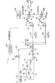
- FIG. 1 is an overall configuration diagram showing an outline of the LNG transfer system 1 according to the first embodiment.
- the LNG transfer system 1 transfers the LNG stored in the land storage tank 3 to the LNG carrier 5 at sea via the transfer line 4.
- the storage tank 3 is provided with a fluid receiving pipe 7 and a BOG (Boil Off Gas) pipe 9.
- the fluid receiving pipe 7 penetrates the upper wall 3a of the storage tank 3 and supplies LNG from the outside into the storage tank 3.
- the fluid receiving pipe 7 has a vertical portion 7a extending in the vertical direction.
- the BOG pipe 9 penetrates the upper wall 3a of the storage tank 3 and discharges the LNG boil-off gas generated in the storage tank 3 to the outside.
- the BOG pipe 9 has a vertical portion 9a extending in the vertical direction. The lower ends of the vertical portions 7a and 9a are located in the gas phase 11a of the LNG 11 stored in the storage tank 3.
- LNG from the outside is supplied to the fluid receiving pipe 7.
- Such LNG is produced by liquefying natural gas in an LNG liquefaction system (not shown).
- the fluid receiving pipe 7 is provided with an expansion valve 13.
- the LNG from the LNG liquefaction system is expanded by the expansion valve 13 so that the temperature is adjusted to about -162 ° C and flows into the storage tank 3.
- the boil-off gas discharged from the BOG pipe 9 is reliquefied using a compressor and a cooler (not shown).
- the transfer line 4 connects the storage tank 3 and the LNG carrier 5 at sea to transfer LNG.
- the storage tank 3 side that supplies LNG is the upstream side
- the LNG carrier 5 side that receives the LNG is the downstream side.
- a pump (not shown) for transferring LNG is provided near the storage tank 3. Further, a check valve 23 and a flow control valve 25 are sequentially provided on the downstream side of the pump in the transfer line 4.
- bypass branch portion 31 is provided on the land transfer line 4.
- the bypass line 33 connects the bypass branch portion 31 of the transfer line 4 and the fluid receiving pipe 7 of the storage tank 3.
- the connection portion 33a of the bypass line 33 to the fluid receiving pipe 7 is on the downstream side of the expansion valve 13.
- the bypass line 33 has a bypass valve 35, and the bypass valve 35 blocks the inflow of LNG from the transfer line 4 to the bypass line 33 during normal transfer.
- the transfer line 4 on the sea is provided with a loading arm 37 for handling fluid.
- the loading arm 37 is provided with an emergency shutoff device 43 that shuts off the transfer line 4 on the downstream side of the arm main body 41.
- the emergency shutoff device 43 is composed of two emergency shutoff valves 51 and 52 and an emergency disconnection coupler 53 interposed between them.
- the loading arm 37 is provided with an ESD (emergency shutdown) system 55 that operates the emergency shutoff device 43.
- the ESD system 55 is activated in an emergency when an angle abnormality of the arm body 41 occurs, and sends an emergency cutoff signal to the emergency cutoff device 43.
- the emergency shutoff device 43 that has received the emergency shutoff signal operates. Therefore, in the emergency shutoff device 43, the emergency release coupler 53 is opened after the two emergency shutoff valves 51 and 52 are closed.
- the opening of the emergency withdrawal coupler 53 is performed, for example, by controlling the hydraulic pressure.
- the emergency shutoff device 43 is not limited to the configuration shown here. Further, the emergency shutoff device 43 provided on the loading arm 37 does not necessarily have to be provided integrally with the arm main body 41. The emergency shutoff device 43 may be provided at least on the transfer line 4 and may block the flow of LNG on the transfer line 4 in an emergency.
- a shutoff valve 57 for shutting off the transfer line 4 is provided on the sea transfer line 4 and on the upstream side of the loading arm 37. The shutoff valve 57 is closed when the emergency shutoff valve 51 fails, and shuts off the flow of LNG in the transfer line 4.
- the LNG carrier 5 is equipped with a ship-side tank (not shown).
- the LNG from the storage tank 3 is filled in the ship side tank. Further, the upstream end of the ship-side pipe 61 extending from the ship-side tank is connected to one of the emergency shutoff valves 52, and constitutes a part of the transfer line 4.
- the LNG carrier 5 transfers the LNG received from the storage tank 3 to another place.
- the storage tank 3 is provided on land in the present embodiment, the storage tank 3 may be provided on the sea.
- the storage tank 3 may be provided in an FSU (Floating Storage Unit) or FLNG (Floating LNG) on the sea.
- FSU Floating Storage Unit
- FLNG Floating LNG
- all the components including the transfer line 4 may be provided at sea.
- a loading hose is used instead of the loading arm.
- the LNG transfer system 1 is provided with a control device 63.
- the control device 63 receives an emergency shutoff signal from the ESD system 55 notifying the operation of the emergency shutoff device 43 in an emergency, and controls the opening of the bypass valve 35.
- the emergency cutoff signal received by the control device 63 is not limited to that transmitted from the ESD system 55. Any signal indicating the operation of the emergency shutoff device 43 may be transmitted from another device. Further, instead of receiving the emergency shutoff signal, the operator of the LNG transfer system 1 may perform an input operation for controlling the bypass valve 35 in the control device 63.
- the ESD system 55 sends an emergency cutoff signal to the emergency cutoff device 43, and at the same time, sends an emergency cutoff signal to the control device 63. Therefore, in the emergency shutoff device 43 that has received the emergency shutoff signal, the emergency shutoff valves 51 and 52 are closed and the emergency disconnection coupler 53 is opened. Further, the control device 63 that has received the emergency shutoff signal controls the bypass valve 35 from the closed state to the open state.
- the pressure of the fluid receiving pipe 7 is substantially the same as the pressure of the gas phase 11a of the LNG 11 stored in the storage tank 3.
- the LNG of the bypass line 33 stably flows into the storage tank 3 without being affected by the pressure of the LNG supplied from the outside to the fluid receiving pipe 7.
- FIG. 2 is a diagram showing a first modification of the LNG transfer system 1 according to the first embodiment.
- FIG. 3 is a diagram showing a second modification of the LNG transfer system 1 according to the first embodiment.
- the same components as those of the LNG transfer system 1 shown in FIG. 1 are designated by the same reference numerals. However, for convenience of explanation, auxiliary reference numerals AD are added to the numbers of the reference numerals for some of the components.
- the first and second modifications of the LNG transfer system 1 are the same as those of the first embodiment described above, except for the matters particularly mentioned below.
- a storage tank 3, a bypass line 33 connected to the storage tank 3, and a transfer line 4 are added, respectively.
- the second transfer line 4B is provided in addition to the first transfer line 4A corresponding to the transfer line 4 in the first embodiment described above.
- the second transfer line 4B has the same configuration as the first transfer line 4A.
- a transfer line branch portion 71 (hereinafter referred to as “branch portion 71”) is provided on the first transfer line 4A on land and on the downstream side of the bypass branch portion 31.
- the second transfer line 4B branches from the first transfer line 4A at the branch portion 71.
- downstream ends of the third transfer line 4C and the fourth transfer line 4D are connected to the second transfer line 4B branched from the branch portion 71, respectively.
- the upstream ends of the third transfer line 4C and the fourth transfer line 4D are connected to independent storage tanks 3C and 3D, respectively.
- bypass branch portions 31C and 31D are provided on the upstream side of the third transfer line 4C and the fourth transfer line 4D, respectively, and the bypass branch portions 31 correspond to the storage tank 3 via the bypass lines 33C and 33D, respectively. Connected to.
- a further transfer line constituting the downstream side may be added.
- a further transfer line constituting the upstream side and equipment for supplying LNG to the additional transfer line may be added.
- the LNG is transferred from any of the three storage tanks 3, 3C, and 3D via the first transfer line 4A or the second transfer line 4B. Will be done.
- the bypass valves 35, 35C, 35D of the bypass lines 33, 33C, 33D are in the closed state, LNG does not flow through the bypass lines 33, 33C, 33D.
- the emergency shutoff valves 51B and 52B in the second transfer line 4B are closed, and the emergency release coupler 53B is opened.
- the control device 63 that has received the emergency shutoff signal controls the bypass valves 35, 35C, 35D in all the bypass lines 33, 33C, 33D so as to change from the closed state to the open state.
- the LNG transfer system 1 can include a plurality of transfer lines 4A and 4B connected to one storage tank 3. Also in this case, a part of the liquefied fluid in the blocked transfer line 4A or transfer line 4B flows into the storage tank via the bypass line 33. Therefore, the pressure surge generated in the plurality of transfer lines connected to one storage tank 3 can be alleviated.
- FIG. 4 is an overall configuration diagram showing an outline of the LNG transfer system 1 according to the second embodiment.
- the same components as those of the LNG transfer system 1 shown in FIG. 1 are designated by the same reference numerals.
- the LNG transfer system 1 according to the second embodiment is the same as that of the first embodiment or a modification thereof, except for the matters specifically mentioned below.
- bypass line 33 is connected to the bypass branch portion 31 of the transfer line 4 and the BOG pipe 9 of the storage tank 3.
- connection portion 33b of the bypass line 33 in the BOG pipe 9 the pressure in the pipe is substantially the same as the pressure in the gas phase 11a of the LNG 11 stored in the storage tank 3. According to this, the LNG of the bypass line 33 stably flows into the storage tank 3 without being affected by the pressure of the boil-off gas discharged to the outside from the BOG pipe 9.
- the LNG transfer system 1 according to the second embodiment can also be provided with a plurality of storage tanks 3 and a plurality of transfer lines 4 connected to the storage tank 3 as in the modified example of the LNG transfer system 1 according to the first embodiment.
- the bypass line 33 may be further connected to the fluid receiving pipe 7 by being branched in the middle, as in the case of the first embodiment. In that case, it is selected whether the LNG flowing through the bypass line 33 flows into the fluid receiving pipe 7 or the BOG pipe 9 by opening / closing a valve (not shown) provided on the fluid receiving pipe 7 side and the BOG pipe 9 side, respectively. You may.
- the system for transferring a fluid and the method for transferring a fluid according to the present invention are applicable not only to LNG but also to a fluid that vaporizes at room temperature.
- LPG may be used as the fluid that vaporizes at room temperature.
Landscapes
- Engineering & Computer Science (AREA)
- Mechanical Engineering (AREA)
- General Engineering & Computer Science (AREA)
- Chemical & Material Sciences (AREA)
- Combustion & Propulsion (AREA)
- Ocean & Marine Engineering (AREA)
- Filling Or Discharging Of Gas Storage Vessels (AREA)
Abstract
【課題】ローディングアームの緊急遮断装置の作動により流体を移送する移送ラインが遮断された場合でも、移送ラインで発生する圧力サージを緩和する。 【解決手段】流体を移送するシステムが、貯蔵タンクとLNG船とを接続する移送ラインと、移送ラインに設けられたローディングアームと、移送ラインを遮断する緊急遮断装置と、移送ラインと貯蔵タンクとを接続するバイパスラインと、バイパスラインに設けられたバイパス弁と、を備え、貯蔵タンクは、流体を外部から受け入れるための流体受入配管と、貯蔵タンク内で発生した流体のボイルオフガスを外部に排出するためのBOG配管とを有し、バイパスラインは、流体受入配管及び前記BOG配管の少なくとも一方に接続される構成とする。
Description
本発明は、常温で気化する流体を貯蔵タンクに貯蔵し、その貯蔵タンクの流体をLNG船に配管を通して移送する流体を移送するシステム及び流体の移送方法に関する。
特許文献1に記載されたように、陸上設備と海上の浮体式設備との間で流体を移送するシステムでは、配管の接続位置を調節できるローディングアームを用いることが知られている。また、そのようなローディングアームには、例えば浮体式設備の過大な揺動による配管やその周辺機器の破損を防止するために、緊急時に流体移送を遮断し、配管同士の接続を解除する緊急遮断装置が設けられている。
陸上のLNG(Liquefied Natural Gas)の生産設備では、生産されたLNGは、貯蔵タンクに一旦貯蔵された後に、LNG移送システムによって所定のタイミングで貯蔵タンクからLNG船に移送される。LNGは、10,000-12,000m3/h程度の大流量で移送ラインの配管内を移送されることもある。また、LNGの移送ラインには、緊急遮断装置を有するローディングアームが設けられることが知られている。
そのようなLNG移送システムでは、緊急事態の発生により緊急遮断装置が作動すると、LNGの移送ラインに設けられた遮断弁によって大流量のLNGの流れが急に遮断される場合がある。このとき、慣性を有するLNGの流れが急に止められるため、その遮断弁付近でのLNGの圧力が急激に上昇して大きな圧力サージが生じる。また、このとき、LNGの流れが遮断弁から貯蔵タンク側に逆流する、すなわちLNGの圧力波が遮断弁から貯蔵タンク側に反射する。そこで、貯蔵タンク側に逆流したLNGの流れは、貯蔵タンク側に設けられた弁等によって遮断され、再びローディングアーム側に向けられる。その結果、LNGの流れは移送ラインを繰り返し往復し、これによりLNGの急激な圧力変動が繰り返される。さらに、遮断弁付近では、LNGの逆流により配管内のLNGの圧力がその飽和蒸気圧以下となることで気体が発生する。そこで発生した気体は、貯蔵タンク側で再びローディングアーム側に向けられたLNGの流れと衝突し気体がつぶされることで大きな圧力変動を生じさせる。
そのような圧力サージの発生は、配管やその周辺機器の故障の原因となり得る。また、そのような圧力サージは、LNGの移送に限らず、少なくとも常温で気化する他の流体の移送においても同様に生じ得る。
そこで、緊急時に発生する圧力サージを緩和するために、緊急時に移送ラインを流れるLNGの一部を一時的に貯留するサージドラムを設けることが考えられる。しかしながら、そのようなサージドラムは大流量のLNGを受け入れるために大きな容量を必要とする。その結果、サージドラムのための大規模な設備が必要となってその設備コストも嵩む。
本発明は、その移送ラインで発生する圧力サージを緩和する。
本発明の第1の側面では、常温で気体であってかつ冷却により液化された流体を移送するシステムであって、前記流体を貯蔵する貯蔵タンクと、前記貯蔵タンクとLNG船とを接続する移送ラインと、前記移送ラインに設けられたローディングアームと、前記ローディングアームに設けられ、前記移送ラインを遮断する緊急遮断装置と、前記移送ラインにおいて前記ローディングアームの上流側に設けられた分岐部と前記貯蔵タンクとを接続するバイパスラインと、前記バイパスラインに設けられ、前記流体の移送時に閉状態にあるバイパス弁と、を備え、前記貯蔵タンクは、前記流体を外部から受け入れるための流体受入配管と、前記貯蔵タンク内で発生した前記流体のボイルオフガスを外部に排出するためのBOG配管とを有し、前記バイパスラインは、前記流体受入配管及び前記BOG配管の少なくとも一方に接続される構成とする。
これによると、ローディングアームを備えたシステムにおいて、ローディングアームの緊急遮断装置の作動により流体を移送する移送ラインが遮断された場合でも、移送ライン内の流体の一部がバイパスラインを介して貯蔵タンクに流入するため、移送ラインで発生する圧力サージを緩和することができる。
本発明の第2の側面では、前記バイパス弁を制御する制御装置を更に備え、前記制御装置は、前記緊急遮断装置が作動した場合には、前記バイパス弁を閉状態から開状態とする構成とする。
これによると、緊急遮断装置が作動した場合にバイパス弁を閉状態から開状態とするように制御できる。
本発明の第3の側面では、前記貯蔵タンク、前記貯蔵タンクに接続される前記バイパスライン、及び前記移送ラインをそれぞれ複数備え、前記複数の移送ラインは、相互に接続され、前記制御装置は、前記緊急遮断装置が作動した場合には、前記バイパスラインのいずれかの前記バイパス弁を閉状態から開状態とする構成とする。
これによると、複数の移送ラインのうちの1つの移送ラインが緊急遮断装置の作動により遮断された場合でも、その遮断された移送ライン内の流体の一部がバイパスラインを介して対応する貯蔵タンクに流入するため、複数の貯蔵タンクに接続された複数の移送ラインで発生する圧力サージ緩和することができる。
本発明の第4の側面では、前記移送ラインを複数備え、前記制御装置は、前記複数の移送ラインのいずれかに対応する前記緊急遮断装置が作動した場合には、前記バイパスラインの前記バイパス弁を閉状態から開状態とする構成とする。
これによると、複数の移送ラインのうちのいずれかが緊急遮断装置の作動により遮断された場合でも、その遮断された移送ライン内の流体の一部がバイパスラインを介して貯蔵タンクに流入するため、1つの貯蔵タンクに接続された複数の移送ラインで発生する圧力サージを緩和することができる。
本発明の第5の側面では、前記移送ラインに設けられた前記分岐部は陸上に位置し、前記ローディングアームは海上に位置する構成とする。
これによると、ローディングアームが海上に位置する場合でもバイパスラインの全体を陸上に設けることが可能となるため、安価な構成により移送ラインで発生する圧力サージを緩和することができる。
本発明の第6の側面では、前記バイパスラインが接続される前記流体受入配管内または前記BOG配管内の少なくとも一方の圧力は、前記貯蔵タンク内の気相の圧力と同一である構成とする。
これによると、流体受入配管に外部から受け入れられる流体またはBOG配管から外部に排出されるボイルオフガスの圧力の影響を受けることなく、バイパスラインを介して流体が貯蔵タンクに安定的に流入する。
本発明の第7の側面では、常温で気体であってかつ冷却により液化された流体を移送するシステムによる流体の移送方法であって、前記システムは、前記流体を貯蔵する陸上の貯蔵タンクと、前記流体をLNG船に移送するべく、前記貯蔵タンクと前記LNG船とを接続する移送ラインと、前記移送ラインに設けられたローディングアームと、前記ローディングアームに設けられ、前記移送ラインを遮断する緊急離脱装置と、前記移送ラインにおいて前記ローディングアームの上流側に設けられた分岐部と前記貯蔵タンクとを接続するバイパスラインと、前記バイパスラインに設けられ、前記流体の移送時に閉状態にあるバイパス弁と、を備え、前記貯蔵タンクは、前記流体を外部から受け入れるための流体受入配管と、前記貯蔵タンク内で発生した前記流体のボイルオフガスを外部に排出するためのガス排出配管とを有し、前記バイパスラインは、前記流体受入配管及び前記ガス排出配管の少なくとも一方に接続され、前記緊急離脱装置が作動した場合には、前記バイパス弁を開状態とする構成とする。
これによると、ローディングアームを備えたシステムにおいて、ローディングアームの緊急遮断装置の作動により流体を移送する移送ラインが遮断された場合でも、移送ライン内の流体の一部がバイパスラインを介して貯蔵タンクに流入するため、移送ラインで発生する圧力サージを緩和することができる。
本発明の第8の側面では、前記システムは、前記貯蔵タンク、前記貯蔵タンクに接続される前記バイパスライン、及び前記移送ラインをそれぞれ複数備え、前記複数の移送ラインは、相互に接続され、前記緊急遮断装置が作動した場合には、前記バイパスラインの前記バイパス弁を閉状態から開状態とする構成とする。
これによると、複数の移送ラインのうちの1つの移送ラインが緊急遮断装置の作動により遮断された場合でも、その遮断された移送ライン内の流体の一部がバイパスラインを介して対応する貯蔵タンクに流入するため、複数の貯蔵タンクに接続された複数の移送ラインで発生する圧力サージを緩和することができる。
本発明の第9の側面では、前記システムは、前記移送ラインを複数備え、前記複数の移送ラインのいずれかに対応する前記緊急遮断装置が作動した場合には、前記バイパスラインの前記バイパス弁を閉状態から開状態とする構成とする。
これによると、複数の移送ラインのうちのいずれかが緊急遮断装置の作動により遮断された場合でも、その遮断された移送ライン内の流体の一部がバイパスラインを介して貯蔵タンクに流入するため、1つの貯蔵タンクに接続された複数の移送ラインで発生する圧力サージを緩和することができる。
このように本発明によれば、その移送ラインで発生する圧力サージを緩和する。
以下、本発明の実施形態について図面を参照しながら説明する。
(第1実施形態)
図1は、第1実施形態に係るLNG移送システム1の概略を示す全体構成図である。
図1は、第1実施形態に係るLNG移送システム1の概略を示す全体構成図である。
LNG移送システム1は、陸上の貯蔵タンク3に貯蔵されたLNGを、移送ライン4を介して海上のLNG船5に移送する。
貯蔵タンク3には、流体受入配管7と、BOG(Boil Off Gas)配管9とが設けられている。流体受入配管7は、貯蔵タンク3の上壁3aを貫通し、LNGを外部から貯蔵タンク3内に供給する。流体受入配管7は上下方向に延在する鉛直部7aを有している。同様に、BOG配管9は、貯蔵タンク3の上壁3aを貫通し、貯蔵タンク3内で発生したLNGのボイルオフガスを外部に排出する。BOG配管9は上下方向に延在する鉛直部9aを有している。それら鉛直部7a、9aの下端は、貯蔵タンク3に貯蔵されたLNG11の気相11aに位置する。
流体受入配管7には、外部からのLNGが供給される。そのようなLNGは、図示しないLNG液化システムにおいて天然ガスを液化することによって生成される。流体受入配管7には、膨張弁13が設けられている。LNG液化システムからのLNGは、膨張弁13によって膨張し、これにより、温度を約-162℃に調整されて貯蔵タンク3に流入する。
BOG配管9から排出されるボイルオフガスは、図示しないコンプレッサ及び冷却器を用いて再液化される。
移送ライン4は、LNGを移送するべく貯蔵タンク3と海上のLNG船5とを接続する。以下の説明では、移送ライン4について、LNGを供給する貯蔵タンク3側を上流側とし、LNGを受け入れるLNG船5側を下流側とする。
移送ライン4では、貯蔵タンク3の付近にLNGを移送するポンプ(図示しない)が設けられている。また、移送ライン4におけるポンプの下流側には、逆止弁23及び流調弁25が順に設けられている。
また、陸上の移送ライン4にはバイパス分岐部31が設けられている。バイパスライン33は、移送ライン4のバイパス分岐部31と貯蔵タンク3の流体受入配管7とを接続する。バイパスライン33の流体受入配管7に対する接続部33aは、膨張弁13の下流側となる。バイパスライン33はバイパス弁35を有し、通常移送時にバイパス弁35は移送ライン4からバイパスライン33へのLNGの流入を遮断する。
また、海上の移送ライン4には、流体荷役用のローディングアーム37が設けられている。ローディングアーム37には、そのアーム本体41の下流側に移送ライン4を遮断する緊急遮断装置43が設けられている。緊急遮断装置43は2つの緊急遮断弁51、52と、その間に介在した緊急離脱カプラー53により構成される。
また、ローディングアーム37は、緊急遮断装置43を作動させるESD(緊急シャットダウン)システム55を備えている。ESDシステム55は、アーム本体41の角度異常が発生した緊急時に発動し、緊急遮断装置43に緊急遮断信号を送出する。これにより、緊急遮断信号を受信した緊急遮断装置43が作動する。そこで、緊急遮断装置43では、2つの緊急遮断弁51、52が閉じられた後に、緊急離脱カプラー53が開放される。緊急離脱カプラー53の開放は、例えば油圧の制御によって行われる。
なお、緊急遮断装置43は、ここに示した構成に限らない。また、ローディングアーム37に設けられる緊急遮断装置43は、必ずしもアーム本体41と一体に設けられる必要はない。緊急遮断装置43は、少なくとも移送ライン4に設けられ、緊急時に移送ライン4におけるLNGの流れを遮断するものであればよい。
また、海上の移送ライン4で、かつローディングアーム37の上流側には、移送ライン4を遮断する遮断弁57が設けられている。遮断弁57は、緊急遮断弁51の故障時に閉状態となり、移送ライン4におけるLNGの流れを遮断する。
LNG船5は、図示しない船側タンクを備えている。貯蔵タンク3からのLNGは船側タンクに充填される。また、船側タンクから延びる船側配管61は、その上流端が一方の緊急遮断弁52に接続され、移送ライン4の一部を構成する。LNG船5は、貯蔵タンク3から受け入れたLNGを他所に移送する。
なお、本実施形態では、貯蔵タンク3が陸上に設けられた例を示したが、貯蔵タンク3は海上に設けられてもよい。貯蔵タンク3は、海上のFSU(Floating Storage Unit)やFLNG(Floating LNG)などに設けられ得る。また、LNG移送システム1では、移送ライン4を含む全ての構成要素が海上に設けられてもよい。FLNGからLNG船5へのLNGの移送では、ローディングアームの代わりに、ローディングホースが用いられる。
また、LNG移送システム1は、制御装置63が設けられている。制御装置63は、緊急時に緊急遮断装置43の作動を知らせる緊急遮断信号をESDシステム55から受信し、バイパス弁35の開の制御をする。なお、制御装置63が受信する緊急遮断信号は、ESDシステム55から送信されるものに限らない。緊急遮断装置43の作動を知らせる信号であれば、他の装置から送信されてもよい。また、緊急遮断信号を受信する代わりに、LNG移送システム1のオペレータが、制御装置63において、バイパス弁35を制御するための入力操作を行ってもよい。
LNGの移送運転時には、移送ライン4のポンプによって貯蔵タンク3内のLNG11が海上のLNG船5に向けて移送される。このとき、バイパスライン33のバイパス弁35は閉状態にあるため、LNGがバイパスライン33を流れることはない。
LNGの移送運転時に、緊急事態が発生すると、ESDシステム55が、緊急遮断装置43に対して緊急遮断信号を送出し、これと同時に、制御装置63に対して緊急遮断信号を送出する。そこで、緊急遮断信号を受信した緊急遮断装置43では、緊急遮断弁51、52が閉じられ、緊急離脱カプラー53が開放される。また、緊急遮断信号を受信した制御装置63は、バイパス弁35を閉状態から開状態に制御する。
この場合、移送ライン4におけるLNGの移送方向の流れは、緊急遮断弁51によって遮断される。一方で、移送ライン4内のLNG11の一部がバイパス分岐部31からバイパスライン33に流入する。さらに、バイパスライン33に流入したLNGは、流体受入配管7を介して貯蔵タンク3に流入する。このようなバイパスライン33により、移送ライン4におけるLNGの流れの急な遮断によって発生する圧力サージが緩和される。なお、緊急遮断弁51から貯蔵タンク3への移送ライン4を介したLNGの逆流は、逆止弁23によって止められる。
また、バイパスライン33の接続部33aでは、流体受入配管7の圧力は、貯蔵タンク3内に貯蔵されたLNG11の気相11aの圧力と略同一である。これにより、バイパスライン33のLNGは、外部から流体受入配管7に供給されるLNGの圧力の影響を受けることなく、貯蔵タンク3に安定的に流入する。
図2は、第1実施形態に係るLNG移送システム1の第1の変形例を示す図である。図3は、第1実施形態に係るLNG移送システム1の第2の変形例を示す図である。図2及び図3では、図1に示したLNG移送システム1と同様の構成要素について同一の符号が付されている。ただし、説明の便宜上、一部の構成要素については、符号の数字に補助的な符号A-Dが付されている。また、LNG移送システム1の第1及び第2の変形例については、以下で特に言及した事項を除き、上述の第1実施形態の場合と同様とする。
LNG移送システム1の第1の変形例では、貯蔵タンク3、貯蔵タンク3に接続されるバイパスライン33、及び移送ライン4がそれぞれ追加される。第1の変形例では、上述の第1実施形態における移送ライン4に相当する第1移送ライン4Aに加え、第2移送ライン4Bが設けられている。第2移送ライン4Bは、第1移送ライン4Aと同様の構成を有している。
図2に示すように、陸上の第1移送ライン4Aで、かつバイパス分岐部31の下流側には移送ライン分岐部71(以下、「分岐部71」という。)が設けられている。第2移送ライン4Bは分岐部71にて第1移送ライン4Aから分岐する。
また、分岐部71から分岐した第2移送ライン4Bには、第3移送ライン4C及び第4移送ライン4Dの下流端がそれぞれ接続されている。第3移送ライン4C及び第4移送ライン4Dの上流端は、それぞれ独立した貯蔵タンク3C、3Dに接続される。また、第3移送ライン4C及び第4移送ライン4Dの上流側には、それぞれバイパス分岐部31C、31Dが設けられ、それらバイパス分岐部31は、バイパスライン33C、33Dを介して対応する貯蔵タンク3に接続される。
なお、第1移送ライン4A及び第2移送ライン4Bに加え、下流側を構成する更なる移送ラインを追加してもよい。また、第3移送ライン4C及び第4移送ライン4Dに加え、上流側を構成する更なる移送ライン及びそれにLNGを供給するための設備を追加してもよい。
LNG移送システム1の第1の変形例では、LNGの移送運転時には、3つの貯蔵タンク3、3C、3Dのうちのいずれかから第1移送ライン4Aまたは第2移送ライン4Bを介してLNGが移送される。このとき、各バイパスライン33、33C、33Dのバイパス弁35、35C、35Dは閉状態にあるため、LNGが各バイパスライン33、33C、33Dを流れることはない。
例えば、第2移送ライン4B及び第3移送ライン4Cを用いたLNGの移送運転時に緊急事態が発生すると、第2移送ライン4Bにおける緊急遮断弁51B、52Bが閉じられ、緊急離脱カプラー53Bが開放される。また、緊急遮断信号を受信した制御装置63は、全てのバイパスライン33、33C、33Dにおけるバイパス弁35、35C、35Dを閉状態から開状態とするように制御する。
この場合、第2移送ライン4BにおけるLNGの移送方向の流れは、第2移送ライン4Bの緊急遮断弁51Bによって遮断される。一方で、第2移送ライン4B内のLNG11の一部がLNGを供給していた貯蔵タンク3、3C、3Dの少なくとも1つに対してバイパスライン33、33C、33Dを介して流入する。したがって、複数の貯蔵タンクに接続された複数の移送ラインで発生する圧力サージを緩和することができる。
LNG移送システム1の第2の変形例では、図3に示すように、第1の変形例における第3移送ライン4C及び第4移送ライン4DならびにそれらにLNGを供給する設備が省略される。つまり、LNG移送システム1は、1つの貯蔵タンク3に接続される複数の移送ライン4A、4Bを備えることができる。この場合にも、遮断された移送ライン4Aまたは移送ライン4B内の液化流体の一部がバイパスライン33を介して貯蔵タンクに流入する。したがって、1つの貯蔵タンク3に接続された複数の移送ラインで発生する圧力サージを緩和することができる。
(第2実施形態)
図4は、第2実施形態に係るLNG移送システム1の概略を示す全体構成図である。図4では、図1に示したLNG移送システム1と同様の構成要素について同一の符号が付されている。また、第2実施形態に係るLNG移送システム1については、以下で特に言及した事項を除き、上述の第1実施形態またはその変形例の場合と同様とする。
図4は、第2実施形態に係るLNG移送システム1の概略を示す全体構成図である。図4では、図1に示したLNG移送システム1と同様の構成要素について同一の符号が付されている。また、第2実施形態に係るLNG移送システム1については、以下で特に言及した事項を除き、上述の第1実施形態またはその変形例の場合と同様とする。
第2実施形態に係るLNG移送システム1では、バイパスライン33が、移送ライン4のバイパス分岐部31と貯蔵タンク3のBOG配管9と接続される。
LNGの移送運転時に緊急事態が発生すると、バイパスライン33に流入したLNGは、BOG配管9を介して貯蔵タンク3に流入する。このようなバイパスライン33の利用により、移送ライン4におけるLNGの流れの急な遮断によって発生する圧力サージが緩和される。
また、BOG配管9におけるバイパスライン33の接続部33bでは、配管内の圧力は、貯蔵タンク3内に貯蔵されたLNG11の気相11aの圧力と略同一である。これによると、バイパスライン33のLNGは、BOG配管9から外部に排出されるボイルオフガスの圧力の影響を受けることなく、貯蔵タンク3に安定的に流入する。
なお、第2実施形態に係るLNG移送システム1においても、第1実施形態に係るLNG移送システム1の変形例と同様に、貯蔵タンク3及びそれに接続される移送ライン4を複数備えることができる。また、バイパスライン33は、途中で分岐されることにより、第1実施形態の場合と同様に、更に流体受入配管7に対して接続されてもよい。その場合、流体受入配管7側及びBOG配管9側にそれぞれ設けられる図示しない弁の開閉操作により、バイパスライン33を流れるLNGを、流体受入配管7及びBOG配管9のいずれに流入させるかが選択されてもよい。
以上、本発明を特定の実施形態に基づいて説明したが、これらの実施形態はあくまでも例示であって、本発明はこれらの実施形態によって限定されるものではない。上述の実施形態に示した本発明に係る流体を移送するシステム及び流体の移送方法の各構成要素は、必ずしも全てが必須ではなく、少なくとも当業者であれば本発明の範囲を逸脱しない限りにおいて適宜取捨選択することが可能である。
本発明に係る流体を移送するシステム及び流体の移送方法は、常温で気化する流体であればLNGに限らず適用可能である。例えば、常温で気化する流体としてLPGが用いられてもよい。
1 :LNG移送システム
3 :貯蔵タンク
4 :移送ライン
4A :第1移送ライン
4B :第2移送ライン
4C :第3移送ライン
4D :第4移送ライン
5 :LNG船
7 :流体受入配管
9 :BOG配管
11a:気相
13 :膨張弁
23 :逆止弁
25 :流調弁
31 :バイパス分岐部
33 :バイパスライン
35 :バイパス弁
37 :ローディングアーム
41 :アーム本体
43 :緊急遮断装置
51 :緊急遮断弁
52 :緊急遮断弁
53 :緊急離脱カプラー
55 :ESDシステム
57 :遮断弁
61 :船側配管
63 :制御装置
71 :移送ライン分岐部
3 :貯蔵タンク
4 :移送ライン
4A :第1移送ライン
4B :第2移送ライン
4C :第3移送ライン
4D :第4移送ライン
5 :LNG船
7 :流体受入配管
9 :BOG配管
11a:気相
13 :膨張弁
23 :逆止弁
25 :流調弁
31 :バイパス分岐部
33 :バイパスライン
35 :バイパス弁
37 :ローディングアーム
41 :アーム本体
43 :緊急遮断装置
51 :緊急遮断弁
52 :緊急遮断弁
53 :緊急離脱カプラー
55 :ESDシステム
57 :遮断弁
61 :船側配管
63 :制御装置
71 :移送ライン分岐部
Claims (9)
- 常温で気体であってかつ冷却により液化された流体を移送するシステムであって、
前記流体を貯蔵する貯蔵タンクと、
前記貯蔵タンクとLNG船とを接続する移送ラインと、
前記移送ラインに設けられたローディングアームと、
前記ローディングアームに設けられ、前記移送ラインを遮断する緊急遮断装置と、
前記移送ラインにおいて前記ローディングアームの上流側に設けられた分岐部と前記貯蔵タンクとを接続するバイパスラインと、
前記バイパスラインに設けられ、前記流体の移送時に閉状態にあるバイパス弁と、を備え、
前記貯蔵タンクは、前記流体を外部から受け入れるための流体受入配管と、前記貯蔵タンク内で発生した前記流体のボイルオフガスを外部に排出するためのBOG配管とを有し、
前記バイパスラインは、前記流体受入配管及び前記BOG配管の少なくとも一方に接続されるシステム。 - 前記バイパス弁を制御する制御装置を更に備え、
前記制御装置は、前記緊急遮断装置が作動した場合には、前記バイパス弁を閉状態から開状態とする、請求項1に記載の移送システム。 - 前記貯蔵タンク、前記貯蔵タンクに接続される前記バイパスライン、及び前記移送ラインをそれぞれ複数備え、
前記複数の移送ラインは、相互に接続され、
前記制御装置は、前記緊急遮断装置が作動した場合には、前記バイパスラインのいずれかの前記バイパス弁を閉状態から開状態とする、請求項1または請求項2に記載のシステム。 - 前記移送ラインを複数備え、
前記制御装置は、前記複数の移送ラインのいずれかに対応する前記緊急遮断装置が作動した場合には、前記バイパスラインの前記バイパス弁を閉状態から開状態とする、請求項1または請求項2に記載のシステム。 - 前記移送ラインに設けられた前記分岐部は陸上に位置し、
前記ローディングアームは海上に位置する、請求項1から請求項4のいずれかに記載のシステム。 - 前記バイパスラインが接続される前記流体受入配管内または前記BOG配管内の少なくとも一方の圧力は、前記貯蔵タンク内の気相の圧力と同一である、請求項1から請求項5のいずれかに記載のシステム。
- 常温で気体であってかつ冷却により液化された流体を移送するシステムによる流体の移送方法であって、
前記システムは、
前記流体を貯蔵する貯蔵タンクと、
前記流体をLNG船に移送するべく、前記貯蔵タンクと前記LNG船とを接続する移送ラインと、
前記移送ラインに設けられたローディングアームと、
前記ローディングアームに設けられ、前記移送ラインを遮断する緊急遮断装置と、
前記移送ラインにおいて前記ローディングアームの上流側に設けられた分岐部と前記貯蔵タンクとを接続するバイパスラインと、
前記バイパスラインに設けられ、前記流体の移送時に閉状態にあるバイパス弁と、を備え、
前記貯蔵タンクは、前記流体を外部から受け入れるための流体受入配管と、前記貯蔵タンク内で発生した前記流体のボイルオフガスを外部に排出するためのBOG配管とを有し、
前記バイパスラインは、前記流体受入配管及び前記BOG配管の少なくとも一方に接続され、前記緊急遮断装置が作動した場合には、前記バイパス弁を開状態とする流体の移送方法。 - 前記システムは、前記貯蔵タンク、前記貯蔵タンクに接続される前記バイパスライン、及び前記移送ラインをそれぞれ複数備え、
前記複数の移送ラインは、相互に接続され、
前記緊急遮断装置が作動した場合には、前記バイパスラインのいずれかの前記バイパス弁を閉状態から開状態とする、請求項7に記載の流体の移送方法。 - 前記システムは、前記移送ラインを複数備え、
前記複数の移送ラインのいずれかに対応する前記緊急遮断装置が作動した場合には、前記バイパスラインの前記バイパス弁を閉状態から開状態とする、請求項7に記載の流体の移送方法。
Priority Applications (3)
| Application Number | Priority Date | Filing Date | Title |
|---|---|---|---|
| CA3164340A CA3164340C (en) | 2020-03-13 | System for transferring fluid and fluid transfer method | |
| US17/791,104 US20230032503A1 (en) | 2020-03-13 | 2020-03-13 | System for transferring fluid and fluid transfer method |
| PCT/JP2020/011159 WO2021181669A1 (ja) | 2020-03-13 | 2020-03-13 | 流体を移送するシステム及び流体の移送方法 |
Applications Claiming Priority (1)
| Application Number | Priority Date | Filing Date | Title |
|---|---|---|---|
| PCT/JP2020/011159 WO2021181669A1 (ja) | 2020-03-13 | 2020-03-13 | 流体を移送するシステム及び流体の移送方法 |
Publications (1)
| Publication Number | Publication Date |
|---|---|
| WO2021181669A1 true WO2021181669A1 (ja) | 2021-09-16 |
Family
ID=77672163
Family Applications (1)
| Application Number | Title | Priority Date | Filing Date |
|---|---|---|---|
| PCT/JP2020/011159 Ceased WO2021181669A1 (ja) | 2020-03-13 | 2020-03-13 | 流体を移送するシステム及び流体の移送方法 |
Country Status (2)
| Country | Link |
|---|---|
| US (1) | US20230032503A1 (ja) |
| WO (1) | WO2021181669A1 (ja) |
Citations (7)
| Publication number | Priority date | Publication date | Assignee | Title |
|---|---|---|---|---|
| JPH0534399U (ja) * | 1991-10-14 | 1993-05-07 | 石川島播磨重工業株式会社 | 液化ガス受入用ローデイングアーム内の不活性ガス置換装置 |
| JP2007292180A (ja) * | 2006-04-25 | 2007-11-08 | Chiyoda Corp | 液化ガス設備の保冷循環システム |
| JP2007298052A (ja) * | 2006-04-27 | 2007-11-15 | Ihi Corp | 液化ガス受入管の冷却保持方法および装置 |
| JP2010196823A (ja) * | 2009-02-25 | 2010-09-09 | Chugoku Electric Power Co Inc:The | 低温液化ガス払出し装置 |
| JP2014031829A (ja) * | 2012-08-03 | 2014-02-20 | Chugoku Electric Power Co Inc:The | 残留lng回収方法 |
| JP2016070377A (ja) * | 2014-09-30 | 2016-05-09 | 川崎重工業株式会社 | 液化水素移送システム |
| JP2019132291A (ja) * | 2018-01-29 | 2019-08-08 | Jfeエンジニアリング株式会社 | Lngタンクの蒸発ガス抑制装置及び蒸発ガス抑制方法 |
Family Cites Families (7)
| Publication number | Priority date | Publication date | Assignee | Title |
|---|---|---|---|---|
| US5421161A (en) * | 1993-09-27 | 1995-06-06 | Minnesota Valley Engineering, Inc. | Storage system for cryogenic fluids |
| US7464734B2 (en) * | 2005-08-08 | 2008-12-16 | Xuejie Liu | Self-cooling pipeline system and method for transfer of cryogenic fluids |
| EP2072885A1 (en) * | 2007-12-21 | 2009-06-24 | Cryostar SAS | Natural gas supply method and apparatus. |
| KR101713857B1 (ko) * | 2014-12-05 | 2017-03-09 | 대우조선해양 주식회사 | Lng 추진선박 |
| CN107002931B (zh) * | 2014-12-17 | 2019-06-04 | 国际壳牌研究有限公司 | 具有紧急释放系统的用于递送加压气体的耦合组合件 |
| JP6703837B2 (ja) * | 2016-01-07 | 2020-06-03 | 株式会社神戸製鋼所 | ボイルオフガス供給装置 |
| FR3085948B1 (fr) * | 2018-09-14 | 2020-12-11 | Fmc Tech | Systeme de transfert d'un produit fluide |
-
2020
- 2020-03-13 US US17/791,104 patent/US20230032503A1/en active Pending
- 2020-03-13 WO PCT/JP2020/011159 patent/WO2021181669A1/ja not_active Ceased
Patent Citations (7)
| Publication number | Priority date | Publication date | Assignee | Title |
|---|---|---|---|---|
| JPH0534399U (ja) * | 1991-10-14 | 1993-05-07 | 石川島播磨重工業株式会社 | 液化ガス受入用ローデイングアーム内の不活性ガス置換装置 |
| JP2007292180A (ja) * | 2006-04-25 | 2007-11-08 | Chiyoda Corp | 液化ガス設備の保冷循環システム |
| JP2007298052A (ja) * | 2006-04-27 | 2007-11-15 | Ihi Corp | 液化ガス受入管の冷却保持方法および装置 |
| JP2010196823A (ja) * | 2009-02-25 | 2010-09-09 | Chugoku Electric Power Co Inc:The | 低温液化ガス払出し装置 |
| JP2014031829A (ja) * | 2012-08-03 | 2014-02-20 | Chugoku Electric Power Co Inc:The | 残留lng回収方法 |
| JP2016070377A (ja) * | 2014-09-30 | 2016-05-09 | 川崎重工業株式会社 | 液化水素移送システム |
| JP2019132291A (ja) * | 2018-01-29 | 2019-08-08 | Jfeエンジニアリング株式会社 | Lngタンクの蒸発ガス抑制装置及び蒸発ガス抑制方法 |
Also Published As
| Publication number | Publication date |
|---|---|
| US20230032503A1 (en) | 2023-02-02 |
| CA3164340A1 (en) | 2021-09-16 |
Similar Documents
| Publication | Publication Date | Title |
|---|---|---|
| US10168003B2 (en) | Valve system for an LNG tank | |
| JP2017106568A (ja) | 安全弁システム、タンク、船舶、船舶における安全弁システムの運用方法 | |
| KR102827345B1 (ko) | 가스 퍼징시스템의 역류방지 밸브셋 및 이를 구비하는 선박의 가스 퍼징시스템 | |
| WO2021181669A1 (ja) | 流体を移送するシステム及び流体の移送方法 | |
| CA3164340C (en) | System for transferring fluid and fluid transfer method | |
| OA21007A (en) | System for transferring fluid and fluid transferring method | |
| KR102276359B1 (ko) | Lngc 언로딩 시스템의 안전 장치 | |
| KR101826900B1 (ko) | 화물 저장탱크 및 그의 배관 시스템 | |
| JPH11280996A (ja) | 流体受入方法および流体貯蔵設備 | |
| JP2023529204A (ja) | 液化ガス運搬船の燃料供給システム及び燃料供給方法 | |
| KR200488325Y1 (ko) | Lng 재기화 장치 및 이를 포함하는 선박 | |
| KR102239827B1 (ko) | 선박용 연료가스 공급 시스템 및 방법 | |
| KR102233194B1 (ko) | 재기화설비의 안전시스템 | |
| WO2024154181A1 (ja) | 液化水素設備 | |
| EP2808293A1 (en) | Loading Assembly for conveying a pressurized Gas, and a floating Gas processing Unit | |
| KR102631184B1 (ko) | 선박의 벙커링라인 쿨링시스템 | |
| CN116464906B (zh) | 可自动排气泄压的低温lpg装船系统 | |
| KR101875089B1 (ko) | 부유식 액화천연가스 설비의 이상압력 보호장치 | |
| KR102608686B1 (ko) | 카고 파이핑 시스템 및 lng 로딩 방법 | |
| KR102487006B1 (ko) | Lng 재기화 시스템의 고압펌프 가압 장치 | |
| KR102239706B1 (ko) | 액화가스 재기화 시스템 및 이를 구비하는 선박 | |
| CN116989258B (zh) | 一种低温接收站节能系统及其工作方法 | |
| KR101973040B1 (ko) | Lng 재기화 시스템 및 이를 시동하는 방법 | |
| KR102535973B1 (ko) | Fsu 양방향 무어링 및 비상차단시스템 운용방법 | |
| EP2808294A1 (en) | Loading Assembly and Emergency Disconnection Coupler for conveying a pressurized Gas between a floating Gas processing Unit and another Structure |
Legal Events
| Date | Code | Title | Description |
|---|---|---|---|
| 121 | Ep: the epo has been informed by wipo that ep was designated in this application |
Ref document number: 20924209 Country of ref document: EP Kind code of ref document: A1 |
|
| ENP | Entry into the national phase |
Ref document number: 3164340 Country of ref document: CA |
|
| NENP | Non-entry into the national phase |
Ref country code: DE |
|
| 122 | Ep: pct application non-entry in european phase |
Ref document number: 20924209 Country of ref document: EP Kind code of ref document: A1 |
|
| NENP | Non-entry into the national phase |
Ref country code: JP |