WO2021181498A1 - 基板処理装置、排気流量制御装置及び半導体装置の製造方法 - Google Patents
基板処理装置、排気流量制御装置及び半導体装置の製造方法 Download PDFInfo
- Publication number
- WO2021181498A1 WO2021181498A1 PCT/JP2020/010172 JP2020010172W WO2021181498A1 WO 2021181498 A1 WO2021181498 A1 WO 2021181498A1 JP 2020010172 W JP2020010172 W JP 2020010172W WO 2021181498 A1 WO2021181498 A1 WO 2021181498A1
- Authority
- WO
- WIPO (PCT)
- Prior art keywords
- exhaust
- control valve
- valve body
- flow rate
- gas
- Prior art date
- Legal status (The legal status is an assumption and is not a legal conclusion. Google has not performed a legal analysis and makes no representation as to the accuracy of the status listed.)
- Ceased
Links
Images





Classifications
-
- H—ELECTRICITY
- H10—SEMICONDUCTOR DEVICES; ELECTRIC SOLID-STATE DEVICES NOT OTHERWISE PROVIDED FOR
- H10P—GENERIC PROCESSES OR APPARATUS FOR THE MANUFACTURE OR TREATMENT OF DEVICES COVERED BY CLASS H10
- H10P14/00—Formation of materials, e.g. in the shape of layers or pillars
- H10P14/60—Formation of materials, e.g. in the shape of layers or pillars of insulating materials
Definitions
- the present disclosure relates to a method for manufacturing a substrate processing device, an exhaust flow rate control device, and a semiconductor device.
- a process of forming a silicon nitride (SiN) film or a silicon oxide (SiO) film on a substrate by supplying a processing gas while adjusting the pressure in a processing chamber containing the substrate.
- SiN silicon nitride
- SiO silicon oxide
- An object of the present disclosure is to provide a configuration capable of increasing the diameter of an exhaust line due to miniaturization of a device.
- a configuration including an exhaust flow control device including a seal portion provided on a side facing the opening and a heating portion for heating the flow control valve body to a predetermined temperature or higher.
- FIG. 2A is a diagram for explaining a configuration of an exhaust flow rate control device preferably used in one embodiment of the present disclosure.
- FIG. 2B is an enlarged view for explaining the gas flow of the portion indicated by A in FIG. 2A.
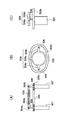
- 3 (A) is a view showing a part of the exhaust flow rate control device,
- FIG. 3 (B) is a top view of FIG. 3 (A), and
- FIG. 3 (C) is FIG. 3 (A). It is a side view of.
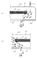
- FIG. 6A is an enlarged view for explaining the gas flow of the portion shown by B in FIG.
- FIG. 6B is an enlarged view for explaining the gas flow of the portion shown by C in FIG.
- FIG. 6A is an enlarged view for explaining the gas flow of the portion shown by B in FIG.
- FIG. 6B is an enlarged view for explaining the gas flow of the portion shown by C in FIG.
- FIG. 6A is an enlarged view for explaining the gas flow of the portion shown by C in FIG.
- FIG. 6B is an enlarged view for explaining the gas flow of the portion shown by C in FIG.
- the processing furnace 202 has a heater 207 as a heating means (heating mechanism).
- the heater 207 has a cylindrical shape and is vertically installed by being supported by a heater base (not shown) as a holding plate.
- a reaction tube 203 forming a reaction vessel is arranged concentrically with the heater 207.
- the reaction tube 203 is made of a heat-resistant material such as quartz (SiO 2 ) or silicon carbide (SiC), and is formed in a cylindrical shape with the upper end closed and the lower end open.
- a processing chamber 201 is formed in the hollow portion of the reaction tube 203.
- the processing chamber 201 is configured to accommodate the wafer 200 as a substrate in a state of being arranged in multiple stages in the vertical direction in a horizontal posture by a boat 217 described later.
- the processing chamber 201 is provided with a nozzle 249 and a nozzle 250 so as to penetrate the lower part of the reaction tube 203.
- the nozzles 249 and 250 are made of a heat resistant material such as quartz or SiC.
- a gas supply pipe 232a is connected to the nozzle 249.
- a gas supply pipe 232c is connected to the nozzle 250.
- the gas supply pipes 232a and 232c are provided with mass flow controllers (MFCs) 241a and 241c which are flow rate controllers (flow control units) and valves 243a and 243c which are on-off valves, respectively, in order from the upstream direction.
- MFCs mass flow controllers
- Gas supply pipes 232b and 232d for supplying the inert gas are connected to the downstream side of the valves 243a and 243c of the gas supply pipes 232a and 232c, respectively.
- the gas supply pipes 232b and 232d are provided with MFCs 241b and 241d and valves 243b and 243d in this order from the upstream direction, respectively.
- the gas supply pipe 232a, the MFC 241a, and the valve 243a form a processing gas supply unit which is a processing gas supply system.
- the gas supply pipe 232c, the MFC 241c, and the valve 243c form a reaction gas supply unit which is a reaction gas supply system.
- the gas supply pipes 232b, 232d, MFC241b, 241d, and valves 243b, 243d constitute an inert gas supply unit which is an inert gas supply system.
- the nozzles 249 and 250 stand up in the annular space between the inner wall of the reaction tube 203 and the wafer 200, respectively, from the lower part to the upper part of the inner wall of the reaction tube 203 toward the upper side in the arrangement direction of the wafer 200. It is provided. That is, the nozzles 249 and 250 are provided along the wafer arrangement region in the region horizontally surrounding the wafer arrangement region on the side of the wafer arrangement region in which the wafer 200 is arranged.
- the nozzles 249 and 250 are each configured as an L-shaped long nozzle, the horizontal portion thereof is provided so as to penetrate the lower side wall of the reaction tube 203, and the vertical portion thereof is at least one end side of the wafer arrangement region. It is provided so as to stand up from the other end side.
- Gas supply holes 249A and 250A for supplying gas are provided on the side surfaces of the nozzles 249 and 250, respectively.
- the gas supply holes 249A and 250A are opened so as to face the center of the reaction tube 203, respectively, so that gas can be supplied toward the wafer 200.
- a plurality of gas supply holes 249A and 250A are provided from the lower part to the upper part of the reaction tube 203, each having the same opening area, and further provided with the same opening pitch.
- the reaction pipe 203 is formed with an exhaust port 251, and the exhaust port 251 is provided with an exhaust pipe 231a for exhausting the atmosphere of the processing chamber 201. That is, the exhaust pipe 231a discharges the gas from the processing chamber 201 to the outside of the processing chamber 201.
- An exhaust flow rate control device 500, an exhaust pipe 231b, and a vacuum pump 246 as an exhaust device are connected to the exhaust pipe 231a in this order from the upstream direction of the gas flow.
- the exhaust flow control device 500 can perform vacuum exhaust and vacuum exhaust stop of the processing chamber 201 and the exhaust flow control device 500 in a state where the vacuum pump 246 is operated, and further, the vacuum pump 246.
- the processing space including the processing chamber 201 and the exhaust flow control device 500 is included. It is a control device configured to be able to adjust the pressure of.
- the exhaust line is mainly composed of the exhaust pipe 231a, the exhaust flow rate control device 500, and the exhaust pipe 231b.
- the vacuum pump 246 may be included in the exhaust line. According to this configuration, it is not necessary to provide a bypass line separate from the conventional exhaust pipe 231a, so that the footprint can be expected to be lowered, and the piping on the exhaust side can be easily routed, so that the installation time is shortened. can.
- the pressure sensor is provided in the exhaust flow rate control device 500 as described above, it goes without saying that the pressure sensor may be provided in the exhaust pipe 231a of the processing chamber 201 as in the conventional case.
- a temperature sensor 263 as a temperature detector is installed in the reaction tube 203.
- the temperature of the processing chamber 201 is configured to have a desired temperature distribution.
- the temperature sensor 263 is L-shaped like the nozzles 249 and 250, and is provided along the inner wall of the reaction tube 203.
- a seal cap 219 is provided as a furnace palate body that can airtightly close the lower end opening of the reaction tube 203.
- the seal cap 219 is made of a metal such as SUS or stainless steel, and is a disk-shaped member.
- An O-ring 220 as a sealing member that comes into contact with the lower end of the reaction tube 203 is provided on the upper surface of the seal cap 219.
- the seal cap 219 is configured to come into contact with the lower end of the reaction tube 203 from the lower side in the vertical direction.
- the boat 217 as a substrate support (board support device) supports a plurality of wafers, for example, 25 to 200 wafers, in a horizontal position and vertically aligned with each other in a multi-stage manner. That is, they are configured to be arranged at intervals.
- the boat 217 is made of a heat resistant material such as quartz or SiC.
- a rotation mechanism 267 as a boat rotation device for rotating the boat 217 is installed.
- the rotating shaft 255 of the rotating mechanism 267 penetrates the seal cap 219 and is connected to the boat 217.
- the rotation mechanism 267 is configured to rotate the wafer 200 by rotating the boat 217.
- the exhaust flow rate control device 500 is provided so as to vertically connect the exhaust pipe 231a and the exhaust pipe 231b vertically.
- the exhaust flow rate control device 500 includes a container unit 502, a flow rate control valve body 504 provided in the container unit 502, and a drive unit 507 that drives the flow rate control valve body 504 up and down.
- the container portion 502 is composed of a cover portion 502a that covers the flow rate control valve body 504 and a plate portion 502b provided at the lower end of the cover portion 502a.
- An opening 503 communicating with the exhaust pipe 231a is formed on the upper surface of the cover portion 502a.
- the plate portion 502b is formed with an opening 505 communicating with the exhaust pipe 231b. That is, the container portion 502 is formed with openings 503 and 505 on the intake side and the exhaust side (upstream side and downstream side of the gas) of the gas exhausted from the processing chamber 201, respectively.
- the area of the opening 505 is larger than the area of the exhaust port 251 of the processing chamber 201. Further, the area of the opening 505 is configured to be equal to or larger than the area of the exhaust pipes 231a and 231b.
- the inner diameters of the exhaust pipes 231a and 231b are, for example, 200 mm or more.
- the flow control valve body 504 is formed in a plate shape integrally with the circular portion 504a having a circular shape larger than the opening 505 and the circular portion 504a, and supports the circular portion 504a. It is composed of two support portions 504b. The two support portions 504b are provided at positions different from each other by 180 degrees on the center line of the circular portion 504a. Support pins 506 are provided on each of the two support portions 504b. That is, the flow control valve body 504 is supported by two support pins 506.
- the two support pins 506 are configured to support the flow control valve body 504 substantially horizontally.
- the two support pins 506 are connected to the drive unit 507, respectively.
- the drive unit 507 synchronizes the two support pins 506 to move them up and down.
- the flow control valve body 504 is driven up and down substantially horizontally. That is, the height of the flow rate control valve body 504 is adjusted by the synchronized drive of the drive unit 507, and the flow rate control valve body 504 is configured to cover the opening 505. That is, the opening 505 is opened and closed by moving the flow control valve body 504 in the container portion 502 in the vertical direction.
- Two or more support pins 506 may be provided.
- the flow rate control device 500 controls the flow rate of the exhaust gas by changing the conductance (easiness of flow) by the vertical movement of the flow rate control valve body 504 above the opening 505.
- a heating unit 508 is embedded in the flow control valve body 504.
- the heating portion 508 may be embedded near the center of the circular portion 504a of the flow control valve body 504, or may be embedded around the circular portion 504 of the flow control valve body 504, and is embedded so as to wind around the circular portion 504a.
- the configuration may be changed.
- the heating unit 508 is configured to heat the flow control valve body 504 from the inside to a predetermined temperature (for example, vaporization temperature) or higher. As a result, it is possible to reduce the adhesion of by-products on the surfaces of the container portion 502 and the flow rate control valve body 504.
- the predetermined temperature when the flow rate control valve body 504 by the heating unit 508 is heated is an O-ring or the like.
- the temperature must be below the heat resistant temperature of the O-ring member.
- the lower surface of the flow control valve body 504 (the surface facing the plate portion 502b) and the inner peripheral side of the circular portion 504a serves as a sealing portion for sealing the opening 505.
- An O-ring 510 is provided.
- a groove 509 is formed on the lower surface of the flow control valve body 504 and on the inner circumference of the circular portion 504a, and the O-ring 510 is configured to be fitted in the groove 509. That is, the O-ring 510 is attached to the flow control valve body 504 so as to be fitted in the groove 509, and the O-ring 510 is embedded in the flow control valve body 504.
- the O-ring 510 may be baked and adhered without forming the groove 509 on the inner circumference of the lower surface of the circular portion 504a of the flow rate control valve body 504.
- the O-ring 510 is configured so as not to face the gas flow in the container portion 502, and the portion of the O-ring 510 in contact with the exhausted gas is reduced to be exhausted. It is configured to minimize the range in which the O-ring 510 is exposed to the flow of gas. As a result, the contact of the gas with the O-ring 510 is suppressed, and the deterioration of the O-ring 510 and the leakage due to the adhesion of the by-product to the O-ring 510 are suppressed.
- the O-ring 510 is provided on the side of the flow control valve body 504 facing the exhaust side opening 505, and the flow control valve body 504 is driven downward by the drive unit 507 to be driven downward from the opening 505 to the inside of the container portion 502. Is configured to be hermetically sealed.
- the exhaust flow rate control device 500 is configured to communicate the exhaust pipes 231a and 231b and the flow path of the exhaust gas in the vertical direction with respect to the flow rate control valve body 504. Further, the gas exhausted from the opening 505 is uniformly exhausted by flowing the gas exhausted from the opening 505 from the upper side to the lower side with respect to the flow rate control valve body 504. Specifically, in a plan view, the flow control valve body 504 and the openings 503 and 505 are provided concentrically, and the gas introduced from the opening 503 is introduced between the flow control valve body 504 and the opening 505. Since it is configured to exhaust from the formed flow path, the flow rate of the gas to be opened can be made uniform in the circumferential direction of the flow rate control valve body 504.
- a piping port is connected to the exhaust flow rate control device 500, and air valves 608a, 608b, 608c and a pressure sensor 602, which are on-off valves, are further connected by joints.
- a pressure sensor 604 is connected to the air valve 608b. By closing the air valve 608b, it is possible to prevent unnecessary gas from hitting the pressure sensor 604 except when the pressure is controlled by the pressure control controller 520.
- the air valve 608b may not be provided.
- a pressure switch 606 is connected to the air valve 608c.
- the pressure switch 606 detects when the processing space including the processing chamber 201 and the exhaust flow rate control device 500 is at atmospheric pressure or higher. That is, the pressure switch 606 detects the overpressurized state of the processing space including the processing chamber 201 and the exhaust flow rate control device 500.
- the pressure sensors 602, 604 and the pressure switch 606 are connected to the processing chamber 201 and the exhaust flow rate control device 500, and press the pressure in the space including both the processing chamber 201 and the exhaust flow rate control device 500 (inside the container portion 502). It is configured to detect.
- the pressure sensor 602 one that detects the pressure band from vacuum to atmospheric pressure is used.
- the pressure sensor 602 has a wider working pressure band than the pressure sensor 604, but its detection accuracy is coarser than that of the pressure sensor 604.
- a 10 torr meter having a limited working pressure band can be used as the pressure sensor 604.
- the pressure band for which the accuracy of this 10 torr meter is guaranteed is 1 to 10 torr (about 133 Pa to 1333 Pa).
- the pressure sensor 604 has higher detection accuracy than the pressure sensor 602.
- the pressure sensor 604 use a 1 torr meter (number of working pressure bands mtorr to 1 torr), a 100 torr meter (working pressure band 1 to 100 torr), a 1000 torr meter (working pressure band 100 to 1000 torr), or the like, depending on the pressure band to be used. Can be done. That is, in the exhaust flow control device 500, by using both the pressure sensor 602 and the pressure sensor 604, it is possible to correspond to the pressure control in a wide band, and the processing pressure is controlled by the pressure control controller 520. ing.
- the pressure sensors 602, 604 and the pressure switch 606 may be provided in the exhaust pipe 231a (preferably near the exhaust port 251). For example, due to the routing of the exhaust pipe 231a from the exhaust port 251 of the processing chamber 201 to the exhaust flow control device 500, a pressure difference may occur between the exhaust pressure near the exhaust port 251 of the exhaust pipe 231a and the pressure of the container portion 502. Even if there is, the pressure in the processing chamber 201 can be detected. Further, in this case, pressure sensors may be provided in both the vicinity of the exhaust port 251 of the exhaust pipe 231a and the container portion 502.
- An auxiliary gas supply unit 512 as a supply unit for supplying the auxiliary gas is connected to the air valve 608a.
- the auxiliary gas supply unit 512 is connected to the exhaust flow rate control device 500 at a position different from the exhaust pipe 231a via the air valve 608a. Further, the auxiliary gas supply unit 512 is connected to the outer peripheral side of the opening 503 of the cover unit 502a.
- the auxiliary gas supply unit 512 is used as a dilution line for supplying auxiliary gas to the exhaust flow rate control device 500 (inside the container unit 502) to dilute the gas in the container unit 502.
- An inert gas such as N 2 gas is used as the auxiliary gas.
- auxiliary gas such as an inert gas
- the inside of the container unit 502 becomes a nitrogen atmosphere. can do.
- this auxiliary gas it is possible to safely exhaust by diluting the concentration of exhaust gas such as H 2 gas.
- the gas flow to the flow path formed between the flow rate control valve body 504 and the opening 505 can be made uniform.
- the exhaust flow rate control device 500 is provided with a discharge section 514 for discharging the atmosphere in the processing chamber 201 and the container section 502, and a discharge section 515 as a bypass line.
- the discharge portion 514 and the discharge portion 515 are provided on the plate portion 502b of the container portion 502 which is the same as the opening 505, but the present invention is not limited to this form, and the discharge portion 514 and the discharge portion 515 may be provided on the cover portion 502a (particularly the side wall). good. Rather, it is preferable to consider the influence on the flow rate of the gas exhausted from the opening 505.
- An air valve 608d is provided in the discharge unit 514.
- the air valve 608d for example, a valve with a spring that prevents the backflow of the discharged gas is used. Then, when the inside of the processing chamber 201 and the exhaust flow control device 500 is in an overpressurized state, a signal indicating the overpressurized state in the processing chamber 201 or the exhaust flow control device 500 is detected from the pressure switch 606.
- the pressure control controller 520 is configured to open the air valve 608d that opens to the atmosphere and exhaust the exhaust gas from the exhaust unit 514. Further, the pressure control controller 520 is configured to open the air valve 608d and discharge the atmosphere inside the container portion 502 to the outside of the container portion 502 when the opening 505 is closed by the flow control valve body 504.
- the discharge portion 515 is configured to connect an opening formed separately from the opening 505 and an exhaust pipe 231b. That is, the discharge section 515 is used as a bypass line for discharging the atmosphere inside the container section 502 to the exhaust pipe 231b without passing through the opening 505 (the gap between the flow rate control valve body 504 and the plate section 502b). Further, the discharge unit 515 is provided with an orifice which is a small hole through which the discharged gas flows, and is used as the first slow exhaust line for evacuating from atmospheric pressure. At this time, the pressure sensor 602 detects the pressure, and when the predetermined pressure is reached, the pressure sensor 604 is switched to. Further, the discharge unit 515 is provided with an air valve 608e.
- the pressure control controller 520 is configured so that when the opening 505 is closed by the flow control valve body 504, the air valve 608e is opened so that the atmosphere in the container portion 502 can be discharged to the exhaust pipe 231b.
- there is only one bypass line but a plurality of bypass lines may be provided, and an APC (Auto Pressure Controller) valve may be provided as one of the bypass lines instead of the air valve. It may be provided.
- the pressure control controller 520 adjusts the opening degree of the APC valve to continue the pressure control. can do.
- a vacuum pump 246 as an exhaust device is connected to the downstream side of the gas flow of the exhaust pipe 231b.
- the exhaust flow rate control device 500 is provided in the vicinity of the vacuum pump 246.
- the flow control valve body 504 With the vacuum pump 246 operating, the flow control valve body 504 is moved up and down by the drive unit 507 to adjust the amount of gas discharged from the opening 505, thereby adjusting the vacuum of the processing chamber 201 and the exhaust flow rate control device 500. Exhaust and vacuum stop is performed. Further, with the vacuum pump 246 operating, the flow control valve body 504 is moved up and down by the drive unit 507 based on the pressure information detected by the pressure sensors 602 and 604 to reduce the amount of gas discharged from the opening 505. By adjusting, the pressure in the processing chamber 201 and the exhaust flow rate control device 500 is adjusted.
- the controller 121 which is a control unit (control means), includes a CPU (Central Processing Unit) 121a, a RAM (Random Access Memory) 121b, a storage device 121c, and an I / O port. It is configured as a computer equipped with 121d.
- the RAM 121b, the storage device 121c, and the I / O port 121d are configured so that data can be exchanged with the CPU 121a via the internal bus 121e.
- An input / output device 122 configured as, for example, a touch panel is connected to the controller 121.
- the storage device 121c is composed of, for example, a flash memory, an HDD (Hard Disk Drive), or the like.
- a control program for controlling the operation of the substrate processing device, a process recipe in which the procedures and conditions for substrate processing described later are described, and the like are readablely stored.
- the process recipes are combined so that the controller 121 can execute each procedure in the substrate processing step described later and obtain a predetermined result, and functions as a program.
- this process recipe, control program, etc. are collectively referred to as a program.
- the term program is used in the present specification, it may include only a process recipe alone, a control program alone, or both.
- the RAM 121b is configured as a memory area (work area) in which programs, data, and the like read by the CPU 121a are temporarily held.
- the I / O port 121d includes the above-mentioned MFC 241a, 241b, 241c, 241d, valves 243a, 243b, 243c, 243d, exhaust flow control device 500, pressure control controller 520, vacuum pump 246, heater 207, temperature sensor 263, and rotation mechanism. It is connected to 267, a boat elevator 115, and the like.
- the exhaust flow control device 500 includes a drive unit 507, a pressure sensor 602, 604, a pressure switch 606, air valves 608a, 608b, 608c, 608d, 608e, a heating unit 508, and the like, and includes a pressure control controller 520. The pressure is controlled by the controller 121 via.
- the CPU 121a is configured to read and execute a control program from the storage device 121c and read a process recipe from the storage device 121c in response to an input of an operation command from the input / output device 122 or the like.
- the CPU 121a adjusts the flow rate of various gases by the MFC 241a, 241b, 241c, and 241d, opens and closes the valves 243a, 243b, 243c, and 243d, and exhausts the pressure via the pressure control controller 520 so as to follow the contents of the read process recipe.
- the pressure control controller 520 may also control the start and stop of the vacuum pump 246.
- the controller 121 is stored in an external storage device (for example, magnetic tape, magnetic disk such as flexible disk or hard disk, optical disk such as CD or DVD, magneto-optical disk such as MO, semiconductor memory such as USB memory or memory card) 123.
- the above-mentioned program can be configured by installing it on a computer.
- the storage device 121c and the external storage device 123 are configured as a computer-readable recording medium. Hereinafter, these are collectively referred to simply as a recording medium.
- recording medium When the term recording medium is used in the present specification, it may include only the storage device 121c alone, it may include only the external storage device 123 alone, or it may include both of them.
- the program may be provided to the computer by using a communication means such as the Internet or a dedicated line without using the external storage device 123.
- This substrate processing step is, for example, one step for manufacturing a semiconductor device.
- a film is formed on the wafer 200 by alternately supplying the first processing gas (raw material gas) and the second processing gas (reaction gas) to the wafer 200 will be described.
- hexachlorodisilane (Si 2 Cl 6 , abbreviated as HCDS) gas is used as a raw material gas
- ammonia (NH 3 ) gas is used as a reaction gas
- a silicon nitride film (Si 3 N 4 film, hereinafter, Si N) is used on the wafer 200.
- Si N silicon nitride film
- a step of supplying HCDS gas to the wafer 200 of the processing chamber 201 there is a step of supplying HCDS gas to the wafer 200 of the processing chamber 201, a step of removing HCDS gas (residual gas) from the processing chamber 201, and a step of supplying the wafer 200 of the processing chamber 201.
- a predetermined film may be formed in advance on the wafer 200, or a predetermined pattern may be formed in advance on the wafer 200 or the predetermined film.
- the wafer 200 is loaded into the boat 217, and the boat 217 is carried into the processing chamber 201. Then, vacuum exhaust (vacuum exhaust) is performed by the vacuum pump 246 so that the space in which the wafer 200 exists has a predetermined pressure (vacuum degree).
- the pressure control controller 520 drives the flow control valve body 504 up and down by the drive unit 507 based on the pressure information detected from the pressure sensors 602 and 604 to drive the pressure in the processing chamber 201 and the exhaust flow control device 500. Let it control the feedback.
- the vacuum pump 246 is always kept in operation until at least the processing of the wafer 200 is completed.
- the wafer 200 in the processing chamber 201 is heated by the heater 207 so as to have a predetermined temperature.
- the state of energization of the heater 207 is feedback-controlled based on the temperature information detected by the temperature sensor 263 so that the processing chamber 201 has a predetermined temperature distribution.
- the flow control valve body 504 is heated by the heating unit 508 so that the temperature becomes equal to or higher than a predetermined temperature. The heating in the processing chamber 201 by the heater 207 and the heating of the flow rate control valve body 504 by the heating unit 508 are continuously performed at least until the processing on the wafer 200 is completed.
- the rotation mechanism 267 starts the rotation of the boat 217 and the wafer 200.
- the rotation mechanism 267 rotates the boat 217 to rotate the wafer 200.
- the rotation of the boat 217 and the wafer 200 by the rotation mechanism 267 is continuously performed at least until the processing on the wafer 200 is completed.
- steps 1 and 2 are sequentially executed.
- Step 1 The valve 243a is opened to allow HCDS gas to flow into the gas supply pipe 232a.
- the flow rate of the HCDS gas is adjusted by the MFC 241a, supplied to the processing chamber 201 via the nozzle 249, and exhausted from the vacuum pump 246 via the exhaust pipe 231a, the exhaust flow rate control device 500, and the exhaust pipe 231b.
- HCDS gas is supplied to the wafer 200.
- the valves 243b and 243d are opened at the same time to allow N 2 gas to flow into the gas supply pipes 232b and 232d.
- the flow rate of the N 2 gas is adjusted by the MFCs 241b and 241d, respectively, and is supplied to the processing chamber 201, and is exhausted from the vacuum pump 246 via the exhaust pipe 231a, the exhaust flow rate control device 500, and the exhaust pipe 231b.
- HCDS gas By supplying HCDS gas to the wafer 200, a silicon (Si) -containing layer having a thickness of less than one atomic layer to several atomic layers is formed as a first layer on the outermost surface of the wafer 200. ..
- the valve 243a is closed to stop the supply of HCDS gas.
- the opening 505 is opened by the flow control valve body 504 of the exhaust flow rate control device 500, and the processing chamber 201 and the inside of the exhaust flow rate control device 500 (inside the container portion 502) are evacuated by the vacuum pump 246.
- the HCDS gas remaining in the processing chamber 201 and the exhaust flow rate control device 500 after contributing to the formation of the unreacted or first layer is discharged from the processing chamber 201.
- the valves 243b and 243d are kept open to maintain the supply of the N 2 gas to the processing chamber 201.
- the N 2 gas acts as a purge gas, which can enhance the effect of discharging the gas remaining in the processing chamber 201 from the processing chamber 201.
- Step 2 After the step 1 is completed, NH 3 gas is supplied to the wafer 200 of the processing chamber 201, that is, the first layer formed on the wafer 200. The NH 3 gas is heat activated and supplied to the wafer 200.
- the valve 243c is opened to allow NH 3 gas to flow into the gas supply pipe 232c.
- the flow rate of the NH 3 gas is adjusted by the MFC 241c, is supplied to the processing chamber 201 via the nozzle 250, and is exhausted from the vacuum pump 246 via the exhaust pipe 231a, the exhaust flow rate control device 500, and the exhaust pipe 231b.
- NH 3 gas is supplied to the wafer 200.
- the valves 243b and 243d are opened at the same time to allow N 2 gas to flow into the gas supply pipes 232b and 232d.
- the flow rate of the N 2 gas is adjusted by the MFCs 241b and 241d, respectively, and is supplied to the processing chamber 201, and is exhausted from the vacuum pump 246 via the exhaust pipe 231a, the exhaust flow rate control device 500, and the exhaust pipe 231b.
- the NH 3 gas supplied to the wafer 200 reacts with at least a part of the first layer formed on the wafer 200, that is, the Si-containing layer in step 1.
- the first layer is changed (modified) into a second layer containing Si and N, that is, a silicon nitride layer (SiN layer).
- the valve 243c is closed and the supply of NH 3 gas is stopped. Then, by the same treatment procedure as in step 1, NH 3 gas and reaction by-products remaining in the treatment chamber 201 after contributing to the formation of the unreacted or second layer are discharged from the treatment chamber 201. At this time, the point that the gas or the like remaining in the processing chamber 201 does not have to be completely discharged is the same as in step 1.
- a SiN film having a predetermined composition and a predetermined film thickness can be formed on the wafer 200 by performing the above-mentioned two steps non-simultaneously, that is, by performing a predetermined number of cycles (n times) without synchronizing them.
- the above cycle is preferably repeated a plurality of times.
- the valves 243b and 243d are opened, N 2 gas is supplied from the gas supply pipes 232b and 232d to the processing chamber 201, and the N 2 gas is supplied to the processing chamber 201 via the exhaust pipe 231a, the exhaust flow rate control device 500, and the exhaust pipe 231b. Exhaust from the vacuum pump 246.
- the N 2 gas acts as a purge gas.
- the treatment chamber 201 is purged, and the gas and reaction by-products remaining in the treatment chamber 201 are removed from the treatment chamber 201 (purge).
- the atmosphere of the treatment chamber 201 is replaced with the inert gas (replacement of the inert gas), and the pressure in the treatment chamber 201 is restored to the normal pressure (return to atmospheric pressure).
- the auxiliary gas into the flow rate control device 500 (inside the container portion 502), the contact of the gas with the O-ring 510 is suppressed, and the gas can be evenly exhausted around the opening 505. Adhesion of products is suppressed. Further, since the gas is uniformly exhausted in the exhaust flow rate control device 500 (particularly around the opening 505), the uneven adhesion of by-products can be reduced. Therefore, the maintenance cycle of the exhaust line can be lengthened. In addition, since the air valve, pressure sensor, pressure switch, etc. are connected to the exhaust flow control device 500 and integrated, the exhaust line can be made smaller than before, and for large-diameter exhaust pipes. Space saving can be realized.
- the exhaust flow rate control device 600 includes the above-mentioned exhaust flow rate control device 500, the position of the opening on the intake side of the container portion connected to the exhaust pipe 231a, and the auxiliary gas supply unit.
- the connection position of 512 is different.
- the exhaust flow rate control device 600 has a container portion 602, and the container portion 602 is composed of a cover portion 602a that covers the flow rate control valve body 504 and a plate portion 602b provided at the lower end of the cover portion 602a.
- An opening 603 that communicates with the exhaust pipe 231a is formed on the side surface of the cover portion 602a.
- the plate portion 602b is formed with an opening 605 communicating with the exhaust pipe 231b.
- the exhaust flow rate control device 600 has an opening 603 formed on the intake side of the gas and an opening 605 formed on the exhaust side.
- the exhaust flow rate control device 600 is configured to be connected substantially horizontally to the exhaust pipe 231a and substantially perpendicular to the exhaust pipe 231b.
- the exhaust flow rate control device 600 discharges the gas to the flow rate control valve body 504 from the side surface direction (from the left direction in FIG. 5) and downward through the opening 605.
- the flow rate control valve body 504 is configured to cover the opening 605.
- the area of the opening 605 is larger than the area of the exhaust port 251 of the processing chamber 201. Further, the area of the opening 605 is configured to be equal to or larger than the area of the exhaust pipes 231a and 231b.
- the auxiliary gas supply unit 512 is connected to the upper surface of the cover unit 602a on the opposite side of the exhaust flow rate control device 600 to which the exhaust pipe 231a is connected via the air valve 608a. That is, the auxiliary gas supply unit 512 is connected to the exhaust pipe 231a at a position different from that of the exhaust pipe 231a via the air valve 608a. Then, by opening the air valve 608a and supplying the auxiliary gas from the auxiliary gas supply unit 512 into the flow rate control device 600 (inside the container unit 602), the mixed gas of the gas introduced from the opening 603 and the auxiliary gas is released. Exhaust from the opening 605.
- the auxiliary gas supply unit 512 may be provided on the side surface of the cover unit 602a on the opposite side on the side to which the exhaust pipe 231a is connected.
- the auxiliary gas supply unit 512 is a cover unit at a position corresponding to an extension of a straight line connecting the center of the flow control valve body 504 (opening 605) and the exhaust pipe 231a (opening 603) in a plan view. It is preferably provided on the side surface of the 602a.
- the flow of the discharged gas may be biased toward the side closer to the processing chamber 201.
- the auxiliary gas is supplied from the side opposite to the exhaust port 251 in which the processing chamber 201 is arranged.
- the configuration is such that a gas flow can be formed. With this configuration, adhesion of by-products is suppressed and uniform exhaust is performed. That is, by opening the air valve 608a of the auxiliary gas supply unit 512, the gas can be evenly exhausted around the opening 605.
- the exhaust pipe 231a is connected to the side surface of the exhaust flow rate control device 600, and the exhaust gas is taken in from the lateral direction with respect to the flow rate control valve body 504.
- the volume (volume of the container portion 602) can be reduced.
- the bias of the exhaust gas from the circumferential direction of the opening 605 can be reduced, and the exhaust gas can be uniformly exhausted.
- heating the flow rate control valve body 504 to a predetermined temperature or higher by heating from the heating unit 508 provided inside the flow rate control valve body 504 adhesion of by-products is reduced.
- the O-ring 510 is provided on the lower surface of the flow rate control valve body 504 so as not to face the gas flow in the container portion 602. Further, since the auxiliary gas supply unit 512 is provided above the outer peripheral side of the O-ring 510, the contact of gas with the O-ring 510 is suppressed as shown in FIG. 6 (A). That is, the range in which the O-ring 510 is exposed to the flow of the exhausted gas is minimized. As a result, the contact of gas with the O-ring 510 is suppressed, and leakage due to deterioration of the O-ring 510 and adhesion of by-products is suppressed.
- the exhaust flow rate control device 600 in the modified example can also obtain the same effect as the exhaust flow rate control device 500 described above.
- FIG. 7 is a diagram showing a modified example of the substrate processing device to which the above-mentioned exhaust flow rate control device 500 can be applied.
- an FPD (flat panel display) device which is one of the substrate processing devices, will be described below.
- the exhaust flow rate control device 500 can also be used as an exhaust line of the LCD device 700 that manufactures the substrate 800, which is a large LCD (liquid crystal display) substrate which is an example of the FPD device.
- the LCD device 700 is not provided with the cover portion 502a of the exhaust flow rate control device 500 described above.
- the LCD device 700 includes a processing container 702 for processing the substrate 800, a gas supply unit 703 for supplying processing gas into the processing container 702, and a gas supply unit for supplying gas to the gas supply unit 703.
- the source 706, the plate heater 802 that heats the substrate 800 while supporting the substrate 800 in the processing chamber 701, and the gas in the processing container 702 are exhausted through the large-diameter exhaust port 705 formed on the bottom surface of the processing container 702. It is composed of an exhaust pipe 704 and.
- the flow rate control valve body 504 is arranged so as to cover the exhaust port 705 from the inside of the processing container 702. Then, the flow control valve body 504 is driven up and down by the drive unit 507 in the processing chamber 701 to open and close the exhaust port 705, and goes out of the processing chamber 701 via the exhaust port 705, the opening 505, and the exhaust pipe 704. It is configured to exhaust gas.
- an example of processing using a substrate processing apparatus which is a batch type vertical apparatus for processing a plurality of substrates at a time or a single-wafer type substrate processing apparatus for processing one substrate at a time.
- the present disclosure is not limited to this, and can be suitably applied to the case of processing using a single-wafer type substrate processing apparatus that processes several substrates at a time.
- the present disclosure is not limited to such a film forming step.
- the process recipe (program that describes the treatment procedure, treatment conditions, etc.) used for forming these various thin films is the content of the substrate treatment (film type, composition ratio, film quality, film thickness, treatment procedure, treatment of the thin film to be formed). It is preferable to prepare each individually (multiple preparations are made) according to the conditions, etc.). Then, when starting the substrate processing, it is preferable to appropriately select an appropriate process recipe from a plurality of process recipes according to the content of the substrate processing.
- the board processing device includes a plurality of process recipes individually prepared according to the content of the board processing via a telecommunication line or a recording medium (external storage device 123) on which the process recipe is recorded. It is preferable to store (install) in the storage device 121c in advance.
- the CPU 121a included in the substrate processing apparatus appropriately selects an appropriate process recipe from the plurality of process recipes stored in the storage device 121c according to the content of the substrate processing. Is preferable.
- thin films of various film types, composition ratios, film qualities, and film thicknesses can be formed with a single substrate processing device in a versatile and reproducible manner. Further, the operation load of the operator (input load of processing procedure, processing condition, etc.) can be reduced, and the board processing can be started quickly while avoiding operation mistakes.
- the present disclosure can also be realized by, for example, changing the process recipe of the existing substrate processing apparatus.
- the process recipe according to the present disclosure may be installed on an existing board processing device via a telecommunications line or a recording medium on which the process recipe is recorded, or input / output of the existing board processing device. It is also possible to operate the device and change the process recipe itself to the process recipe according to the present disclosure.
Landscapes
- Chemical Vapour Deposition (AREA)
Abstract
デバイスの微細化に伴う排気ラインの大口径化に対応可能な構成を提供することができる。 基板を処理する処理室と、処理室からのガスを排出する排気管と、排気管に設けられ、少なくともガスの吸気側と排気側に開口部を有する容器部と、排気側の開口部を覆うように構成される流量制御弁体と、流量制御弁体を駆動させる駆動部と、該駆動部により流量制御弁体を下方に駆動させて排気側の開口部から容器部内を密閉可能なように、流量制御弁体の排気側の開口部に対向する側に設けられるシール部と、流量制御弁体を所定温度以上に加熱する加熱部と、を含む排気流量制御装置を備えた構成が提供される。
Description
本開示は、基板処理装置、排気流量制御装置及び半導体装置の製造方法に関する。
半導体装置の製造工程の一工程として、基板を収容した処理室内の圧力を調整しながら処理ガスを供給することで、基板上にシリコン窒化(SiN)膜やシリコン酸化(SiO)膜を形成する処理が行われることがある(例えば特許文献1参照)。
近年では、従来よりも高真空での成膜が要求されており、装置に大口径の排気ラインを設け、大口径の排気ラインに対応する圧力制御バルブ(以後、APCバルブともいう)の制御が必要とされている。
しかしながら、大口径に対応するAPCバルブは、高真空域での圧力制御に対応させようとすると広帯域の圧力制御に対応させることが難しいものの、今後のデバイスの微細化に伴い成膜条件の厳格化に対応させる必要がある。
本開示は、デバイスの微細化に伴う排気ラインの大口径化に対応可能な構成を提供することを目的とする。
本開示の一態様によれば、
基板を処理する処理室と、
前記処理室からのガスを排出する排気管と、
前記排気管に設けられ、少なくとも前記ガスの吸気側と排気側に開口部を有する容器部と、前記排気側の開口部を覆うように構成される流量制御弁体と、前記流量制御弁体を上下に駆動させる駆動部と、前記駆動部により前記流量制御弁体を下方に駆動させて前記排気側の開口部から前記容器部内を密閉可能なように、前記流量制御弁体の前記排気側の開口部に対向する側に設けられるシール部と、前記流量制御弁体を所定温度以上に加熱する加熱部と、を含む排気流量制御装置と、を備えた構成が提供される。
基板を処理する処理室と、
前記処理室からのガスを排出する排気管と、
前記排気管に設けられ、少なくとも前記ガスの吸気側と排気側に開口部を有する容器部と、前記排気側の開口部を覆うように構成される流量制御弁体と、前記流量制御弁体を上下に駆動させる駆動部と、前記駆動部により前記流量制御弁体を下方に駆動させて前記排気側の開口部から前記容器部内を密閉可能なように、前記流量制御弁体の前記排気側の開口部に対向する側に設けられるシール部と、前記流量制御弁体を所定温度以上に加熱する加熱部と、を含む排気流量制御装置と、を備えた構成が提供される。
本開示によれば、デバイスの微細化に伴う排気ラインの大口径化に対応可能な構成を提供することができる。
(1)基板処理装置の構成
以下、実施形態について、図面を用いて説明する。ただし、以下の説明において、同一構成要素には同一符号を付し繰り返しの説明を省略することがある。なお、図面は説明をより明確にするため、実際の態様に比べ、各部の幅、厚さ、形状等について模式的に表される場合があるが、あくまで一例であって、本開示の解釈を限定するものではない。
以下、実施形態について、図面を用いて説明する。ただし、以下の説明において、同一構成要素には同一符号を付し繰り返しの説明を省略することがある。なお、図面は説明をより明確にするため、実際の態様に比べ、各部の幅、厚さ、形状等について模式的に表される場合があるが、あくまで一例であって、本開示の解釈を限定するものではない。
(処理炉)
図1に示すように、処理炉202は加熱手段(加熱機構)としてのヒータ207を有する。ヒータ207は円筒形状であり、保持板としてのヒータベース(図示せず)に支持されることにより垂直に据え付けられている。
図1に示すように、処理炉202は加熱手段(加熱機構)としてのヒータ207を有する。ヒータ207は円筒形状であり、保持板としてのヒータベース(図示せず)に支持されることにより垂直に据え付けられている。
ヒータ207の内側には、ヒータ207と同心円状に反応容器(処理容器)を構成する反応管203が配設されている。反応管203は、例えば石英(SiO2)または炭化シリコン(SiC)等の耐熱性材料により構成され、上端が閉塞し下端が開口した円筒形状に形成されている。反応管203の筒中空部には、処理室201が形成されている。処理室201は、基板としてのウエハ200を後述するボート217によって水平姿勢で垂直方向に多段に整列した状態で収容可能に構成されている。
処理室201には、ノズル249及びノズル250が、反応管203の下部を貫通するように設けられている。ノズル249,250は、例えば石英またはSiC等の耐熱性材料により構成される。ノズル249には、ガス供給管232aが接続されている。ノズル250には、ガス供給管232cが接続されている。ガス供給管232a,232cには、それぞれ上流方向から順に、流量制御器(流量制御部)であるマスフローコントローラ(MFC)241a,241cおよび開閉弁であるバルブ243a,243cが設けられている。ガス供給管232a,232cのバルブ243a,243cよりも下流側には、それぞれ不活性ガスを供給するガス供給管232b,232dが接続されている。ガス供給管232b,232dには、それぞれ上流方向から順に、MFC241b,241dおよびバルブ243b,243dが設けられている。主に、ガス供給管232a、MFC241a、バルブ243aにより、処理ガス供給系である処理ガス供給部が構成される。また、ガス供給管232c、MFC241c、バルブ243cにより、反応ガス供給系である反応ガス供給部が構成される。また、ガス供給管232b,232d、MFC241b,241d、バルブ243b,243dにより、不活性ガス供給系である不活性ガス供給部が構成される。
ノズル249,250は、それぞれ反応管203の内壁とウエハ200との間における円環状の空間に、反応管203の内壁の下部より上部に沿って、ウエハ200の配列方向上方に向かって立ち上がるように設けられている。すなわち、ノズル249,250は、それぞれウエハ200が配列されるウエハ配列領域の側方の、ウエハ配列領域を水平に取り囲む領域に、ウエハ配列領域に沿うように設けられている。ノズル249,250は、それぞれL字型のロングノズルとして構成されており、その水平部は反応管203の下部側壁を貫通するように設けられており、その垂直部は少なくともウエハ配列領域の一端側から他端側に向かって立ち上がるように設けられている。ノズル249,250の側面には、ガスを供給するガス供給孔249A,250Aがそれぞれ設けられている。ガス供給孔249A,250Aは、それぞれ反応管203の中心を向くようにそれぞれ開口しており、ウエハ200に向けてガスを供給することが可能となっている。ガス供給孔249A,250Aは、それぞれ反応管203の下部から上部にわたって複数設けられ、それぞれが同一の開口面積を有し、更に同じ開口ピッチで設けられている。
反応管203には、排気口251が形成され、排気口251には、処理室201の雰囲気を排気する排気管231aが設けられている。すなわち、排気管231aは、処理室201からのガスを処理室201外へ排出する。排気管231aには、ガス流の上流方向から順に、排気流量制御装置500、排気管231b、排気装置としての真空ポンプ246が接続されている。排気流量制御装置500は、詳細には後述するが、真空ポンプ246を作動させた状態で処理室201及び排気流量制御装置500の真空排気および真空排気停止を行うことができ、更に、真空ポンプ246を作動させた状態で、圧力センサにより検出された圧力情報に基づいて駆動部により流量制御弁を上下させて高さを調節することで、処理室201及び排気流量制御装置500内を含む処理空間の圧力を調整することができるように構成されている制御装置である。主に、排気管231a、排気流量制御装置500及び排気管231bにより、排気ラインが構成される。なお、真空ポンプ246を排気ラインに含めて考えてもよい。この構成によれば、従来の排気管231aと別のバイパスラインを設けなくて良いため、フットプリントの低下を期待でき、また、排気側の配管の引き回しが簡単になるため設置に係る時間を短縮できる。なお、排気流量制御装置500に圧力センサを設けた形態で上述しているが、従来のように処理室201の排気管231aに圧力センサを設けてもよいのは言うまでもない。
反応管203には、温度検出器としての温度センサ263が設置されている。温度センサ263により検出された温度情報に基づきヒータ207への通電具合を調整することで、処理室201の温度が所望の温度分布となるように構成されている。温度センサ263は、ノズル249,250と同様にL字型に構成されており、反応管203の内壁に沿って設けられている。
反応管203の下方には、反応管203の下端開口を気密に閉塞可能な炉口蓋体としてのシールキャップ219が設けられている。シールキャップ219は、例えばSUSやステンレス等の金属からなり、円盤状の部材である。シールキャップ219の上面には、反応管203の下端と当接するシール部材としてのOリング220が設けられている。シールキャップ219は、反応管203の下端に垂直方向下側から当接されるように構成されている。
基板支持具(基板支持装置)としてのボート217は、複数枚、例えば25~200枚のウエハ200を、水平姿勢で、かつ、互いに中心を揃えた状態で垂直方向に整列させて多段に支持するように、すなわち、間隔を空けて配列させるように構成されている。ボート217は、例えば石英やSiC等の耐熱性材料により構成される。
シールキャップ219の処理室201と反対側には、ボート217を回転させるボート回転装置としての回転機構267が設置されている。回転機構267の回転軸255は、シールキャップ219を貫通してボート217に接続されている。回転機構267は、ボート217を回転させることでウエハ200を回転させるように構成されている。
(2)排気流量制御装置500の構成
次に、本実施形態における排気ラインとして用いられる排気流量制御装置500の詳細について図2(A)、図2(B)及び図3(A)~図3(C)を用いて説明する。
次に、本実施形態における排気ラインとして用いられる排気流量制御装置500の詳細について図2(A)、図2(B)及び図3(A)~図3(C)を用いて説明する。
排気流量制御装置500は、排気管231aと排気管231bを上下に縦型に接続するように設けられている。排気流量制御装置500は、容器部502と、容器部502内に設けられる流量制御弁体504と、流量制御弁体504を上下に駆動させる駆動部507と、を備えている。
容器部502は、流量制御弁体504を覆うカバー部502aと、カバー部502aの下端に設けられるプレート部502bと、で構成されている。
カバー部502aの上面には、排気管231aに連通する開口部503が形成されている。プレート部502bには、排気管231bに連通する開口部505が形成されている。つまり、容器部502には、処理室201から排気するガスの吸気側と排気側(ガスの上流側と下流側)にそれぞれ開口部503,505が形成されている。
開口部505の面積は、処理室201の排気口251の面積より大きく構成されている。また、開口部505の面積は、排気管231a,231bの面積と同等もしくはより大きく構成される。なお、排気管231a,231bの内径は例えば200mm以上である。
流量制御弁体504は、図3(B)に示されるように、開口部505よりも大きい円形状の円形部504aと、円形部504aと一体に板状に形成され、円形部504aを支持する2つの支持部504bと、で構成されている。2つの支持部504bは、円形部504aの中心線上に180度異なる位置に設けられている。2つの支持部504bには、それぞれ支持ピン506が設けられている。つまり、流量制御弁体504は、2つの支持ピン506で支持されている。
2つの支持ピン506は、流量制御弁体504を略水平に支持するよう構成されている。2つの支持ピン506は、それぞれ駆動部507に接続されている。駆動部507は、2つの支持ピン506を同期させて上下動作させる。これにより、流量制御弁体504は、上下に略水平に駆動される。すなわち、駆動部507の同期された駆動により、流量制御弁体504は高さが調節され、流量制御弁体504が開口部505を覆うように構成されている。つまり、容器部502内で流量制御弁体504を上下方向に移動させることにより、開口部505が開閉されるように構成されている。なお、支持ピン506は、2つ以上設けてもよい。
すなわち、流量制御装置500は、開口部505上方での流量制御弁体504の上下動作によってコンダクタンス(流れやすさ)を変えることにより排気されるガスの流量制御を行う。
流量制御弁体504には、加熱部508が埋め込まれている。加熱部508は、流量制御弁体504の円形部504aの中央付近に埋め込まれた構成でもよく、流量制御弁体504の周囲に埋め込まれた構成でもよく、円形部504aにとぐろを巻くように埋め込まれた構成でもよい。加熱部508は、流量制御弁体504を内部から所定温度(例えば、気化温度)以上に加熱するように構成されている。これにより、容器部502や流量制御弁体504の表面に副生成物の付着を低減することができる。
以下に後述するように、流量制御弁体504には、シール部としてのOリング510が設けられているため、加熱部508による流量制御弁体504を加熱するときの所定温度は、Oリング等のシール部材の耐熱温度以下になるようにしなければならない。
流量制御弁体504の下面(プレート部502bと対向する面)であって、円形部504aの内周側には、図2(B)に示すように、開口部505を密閉するシール部としてのOリング510が設けられている。流量制御弁体504の下面であって円形部504aの内周には、溝509が形成され、Oリング510は、この溝509内に嵌め込まれるよう構成されている。すなわち、Oリング510は、溝509内に嵌め込むようにして流量制御弁体504に取り付けられ、Oリング510が流量制御弁体504に埋設されるよう構成されている。なお、流量制御弁体504の円形部504aの下面の内周に溝509を形成せずに、Oリング510を焼き付け接着するようにしてもよい。Oリング510は、図2(B)に示すように、容器部502内のガスの流れに対向しないように構成され、Oリング510が排気されるガスに接触する部分を小さくして、排気されるガスの流れに対してOリング510が晒される範囲を最小にして構成されている。これにより、Oリング510へのガスの接触が抑制され、Oリング510の劣化やOリング510への副生成物の付着によるリーク(漏れ)が抑制される。すなわち、Oリング510は、流量制御弁体504の排気側の開口部505に対向する側に設けられ、駆動部507により流量制御弁体504を下方に駆動させて開口部505から容器部502内を密閉可能なように構成している。
図2(A)に示すように、排気流量制御装置500は、流量制御弁体504に対して、上下方向に排気管231a、231bと排気されるガスの流路を連通するように構成されており、更に、開口部505から排気されるガスを、流量制御弁体504に対して上方から下方に流すことで、ガスを均等排気するよう構成されている。具体的には、平面視において、流量制御弁体504と開口部503,505が同心円状に設けられており、開口部503から導入されるガスを流量制御弁体504と開口部505の間に形成される流路から排気するように構成されているので、開口されるガスの流量を流量制御弁体504の周方向で均等にすることができる。
排気流量制御装置500には、配管ポートが接続され、さらに継手によって開閉弁であるエアバルブ608a,608b,608c及び圧力センサ602が接続されている。
エアバルブ608bには、圧力センサ604が接続されている。エアバルブ608bを閉じることにより、圧力制御コントローラ520による圧力制御時以外は、圧力センサ604に不要なガスが当たるのを防止することができる。なお、エアバルブ608bは、設けなくてもよい。
また、エアバルブ608cには、圧力スイッチ606が接続されている。圧力スイッチ606は、処理室201及び排気流量制御装置500を含む処理空間が大気圧以上である場合に検出する。すなわち、圧力スイッチ606は、処理室201及び排気流量制御装置500を含む処理空間の過加圧状態を検出する。
すなわち、圧力センサ602,604及び圧力スイッチ606は、処理室201と排気流量制御装置500に接続され、処理室201と排気流量制御装置500内(容器部502内)の両方を含む空間の圧力を検出するよう構成されている。圧力センサ602として、真空から大気圧までの圧力帯域を検出するものを使用する。圧力センサ602は、圧力センサ604と比較して使用圧力帯域が広域であるが、圧力センサ604と比較して検出精度が荒い。また、圧力センサ604として、使用圧力帯域が限定される10torr計を用いることができる。この10torr計の精度保証される圧力帯域は1~10torr(約133Pa~1333Pa)である。圧力センサ604は、使用圧力帯域が限定されるが、圧力センサ602と比較して検出精度が高い。圧力センサ604として、使用したい圧力帯域に応じて、1torr計(使用圧力帯域数mtorr~1torr)、100torr計(使用圧力帯域1~100torr)、1000torr計(使用圧力帯域100~1000torr)等を用いることができる。つまり、排気流量制御装置500において、圧力センサ602と圧力センサ604の両方を用いることで、広帯域の圧力制御に対応させることが可能となり、圧力制御コントローラ520による処理圧力の制御が行われるよう構成されている。
ここで、処理室201の圧力を測定するため、圧力センサ602,604及び圧力スイッチ606を排気管231a(好ましくは、排気口251の近く)に設けるようにしてもよい。例えば、処理室201の排気口251から排気流量制御装置500までの排気管231aの引き回しにより、排気管231aの排気口251付近での排気圧と容器部502の圧力とで圧力差が生じる場合があっても、処理室201の圧力を検出できる。また、この場合、排気管231aの排気口251付近と容器部502の両方に圧力センサを設けるようにしてもよい。
なお、これらのエアバルブ608a,608b,608c、圧力センサ602,604、圧力スイッチ606を、排気流量制御装置500に搭載し、IGS集積ユニット(集積化ガスシステム)のように埋め込んで一体化させることもできる。このように一体化させることにより、エアバルブ608a,608b,608c等の部品を排気流量制御装置500と共に加熱することができ、加熱、保温効率を向上させることができる。なお、エアバルブ608a,608b,608c等の部品は、配管を介して排気流量制御装置500と接続してもよい。
エアバルブ608aには、補助ガスを供給する供給部としての補助ガス供給部512が接続される。補助ガス供給部512は、排気流量制御装置500の排気管231aとは異なる位置に、エアバルブ608aを介して接続される。また、補助ガス供給部512は、カバー部502aの開口部503よりも外周側に接続されている。補助ガス供給部512は、排気流量制御装置500内(容器部502内)に補助ガスを供給して、容器部502内のガスを希釈する希釈ラインとして用いられる。補助ガスとして、N2ガス等の不活性ガスが用いられる。そして、エアバルブ608aを開にして、補助ガス供給部512から流量制御装置500内(容器部502内)に例えば、不活性ガス等の補助ガスを供給することで、容器部502内を窒素雰囲気にすることができる。また、この補助ガスの供給により、H2ガス等のような排気ガスの濃度を希釈することで安全に排気ができる。また、この補助ガスの供給により、流量制御弁体504と開口部505の間に形成される流路へのガス流れを均等にすることができる。
また、排気流量制御装置500には、処理室201および容器部502内の雰囲気を排出する排出部514と、バイパスラインとしての排出部515が設けられている。なお、排出部514と排出部515が、開口部505と同じ容器部502のプレート部502bに設けられているが、この形態に限定されず、カバー部502a(特に側壁)に設けるようにしてもよい。むしろ、開口部505から排気されるガスの流量への影響を考慮すれば好ましい。
排出部514には、エアバルブ608dが設けられている。エアバルブ608dとして、例えば排出されるガスの逆流を防ぐばね付きのバルブが用いられる。そして、処理室201、排気流量制御装置500内が過加圧状態になった場合に、圧力スイッチ606から、処理室201又は排気流量制御装置500内の過加圧状態を示す信号が検出されると、圧力制御コントローラ520は、大気開放するエアバルブ608dを開にし、排出部514から排気ガスを排気するように構成されている。また、圧力制御コントローラ520は、流量制御弁体504により開口部505を閉塞するときに、エアバルブ608dを開とし、容器部502内の雰囲気を容器部502外へ排出するように構成されている。
排出部515は、開口部505とは別に形成された開口と、排気管231bと、を接続するように構成されている。つまり、排出部515は、容器部502内の雰囲気を、開口部505(流量制御弁体504およびプレート部502bの間の間隙)を通過させずに排気管231bに排出させるバイパスラインとして用いられる。また、排出部515には、排出されるガスを流す小さな穴であるオリフィスが設けられ、大気圧から真空引きする最初のスロー排気ラインとして用いられる。このとき、圧力センサ602で圧力を検出し、所定圧力に到達すると圧力センサ604に切り替えられる。また、排出部515には、エアバルブ608eが設けられている。また、圧力制御コントローラ520は、流量制御弁体504により開口部505を閉塞する際に、エアバルブ608eを開とし、容器部502内の雰囲気を排気管231bへ排出可能なように構成されている。なお、本実施の形態では、バイパスラインが一つであるが、複数のバイパスラインを設けるようにしてもよく、更に、バイパスラインの一つに、エアバルブの代わりにAPC(Auto Pressure Controller)バルブを設けるようにしてもよい。例えば、流量制御弁体504の駆動部507の故障により開口部505が意図しない閉塞状態に陥った際に、圧力制御コントローラ520により上述のAPCバルブの開度を調整することにより、圧力制御を継続することができる。
排気管231bのガス流の下流側には、排気装置としての真空ポンプ246が接続されている。例えば、排気流量制御装置500は、真空ポンプ246に近接して設けられている。真空ポンプ246を作動させた状態で、駆動部507により流量制御弁体504を上下させて開口部505から排出されるガスの量を調整することで、処理室201及び排気流量制御装置500の真空排気および真空排気停止が行われる。更に、真空ポンプ246を作動させた状態で、圧力センサ602、604により検出された圧力情報に基づいて駆動部507により流量制御弁体504を上下させて開口部505から排出されるガスの量を調節することで、処理室201及び排気流量制御装置500内の圧力が調整される。
(3)コントローラ121の構成
図4に示すように、制御部(制御手段)であるコントローラ121は、CPU(Central Processing Unit)121a、RAM(Random Access Memory)121b、記憶装置121c、I/Oポート121dを備えたコンピュータとして構成されている。RAM121b、記憶装置121c、I/Oポート121dは、内部バス121eを介して、CPU121aとデータ交換可能なように構成されている。コントローラ121には、例えばタッチパネル等として構成された入出力装置122が接続されている。
図4に示すように、制御部(制御手段)であるコントローラ121は、CPU(Central Processing Unit)121a、RAM(Random Access Memory)121b、記憶装置121c、I/Oポート121dを備えたコンピュータとして構成されている。RAM121b、記憶装置121c、I/Oポート121dは、内部バス121eを介して、CPU121aとデータ交換可能なように構成されている。コントローラ121には、例えばタッチパネル等として構成された入出力装置122が接続されている。
記憶装置121cは、例えばフラッシュメモリ、HDD(Hard Disk Drive)等で構成されている。記憶装置121c内には、基板処理装置の動作を制御する制御プログラムや、後述する基板処理の手順や条件等が記載されたプロセスレシピ等が、読み出し可能に格納されている。プロセスレシピは、後述する基板処理工程における各手順をコントローラ121に実行させ、所定の結果を得ることが出来るように組み合わされたものであり、プログラムとして機能する。以下、このプロセスレシピや制御プログラム等を総称して、単に、プログラムともいう。本明細書においてプログラムという言葉を用いた場合は、プロセスレシピ単体のみを含む場合、制御プログラム単体のみを含む場合、または、その両方を含む場合がある。RAM121bは、CPU121aによって読み出されたプログラムやデータ等が一時的に保持されるメモリ領域(ワークエリア)として構成されている。
I/Oポート121dは、上述のMFC241a,241b,241c,241d、バルブ243a,243b,243c,243d、排気流量制御装置500、圧力制御コントローラ520、真空ポンプ246、ヒータ207、温度センサ263、回転機構267、ボートエレベータ115等に接続されている。なお、排気流量制御装置500は、上述したように、駆動部507、圧力センサ602,604、圧力スイッチ606、エアバルブ608a,608b,608c,608d,608e、加熱部508等を含み、圧力制御コントローラ520を介してコントローラ121によって圧力制御される。
CPU121aは、記憶装置121cから制御プログラムを読み出して実行すると共に、入出力装置122からの操作コマンドの入力等に応じて記憶装置121cからプロセスレシピを読み出すように構成されている。CPU121aは、読み出したプロセスレシピの内容に沿うように、MFC241a,241b,241c,241dによる各種ガスの流量調整動作、バルブ243a,243b,243c,243dの開閉動作、圧力制御コントローラ520を介しての排気流量制御装置500における圧力センサ602,604から検出される圧力に基づく駆動部507による流量制御弁体504の上下駆動動作による、処理室201及び排気流量制御装置500内を少なくとも含む空間の圧力制御動作、圧力制御コントローラ520を介しての排気流量制御装置500における圧力スイッチ606からの信号検出に基づくバルブ608a,608b,608c,608d,608eの開閉動作、加熱部508の温度調整動作、真空ポンプ246の起動および停止、温度センサ263に基づくヒータ207の温度調整動作、回転機構267によるボート217の回転および回転速度調節動作、ボートエレベータ115によるボート217の昇降動作等を制御するように構成されている。なお、真空ポンプ246の起動および停止も圧力制御コントローラ520が制御するように構成してもよい。
コントローラ121は、外部記憶装置(例えば、磁気テープ、フレキシブルディスクやハードディスク等の磁気ディスク、CDやDVD等の光ディスク、MO等の光磁気ディスク、USBメモリやメモリカード等の半導体メモリ)123に格納された上述のプログラムを、コンピュータにインストールすることにより構成することができる。記憶装置121cや外部記憶装置123は、コンピュータ読み取り可能な記録媒体として構成されている。以下、これらを総称して、単に、記録媒体ともいう。本明細書において記録媒体という言葉を用いた場合は、記憶装置121c単体のみを含む場合、外部記憶装置123単体のみを含む場合、または、その両方を含む場合がある。なお、コンピュータへのプログラムの提供は、外部記憶装置123を用いず、インターネットや専用回線等の通信手段を用いて行ってもよい。
(4)基板処理工程
次に、半導体製造装置としての基板処理装置の処理室201内でウエハ200を処理する基板処理工程の概略について説明する。この基板処理工程は、例えば、半導体装置を製造するための一工程である。ここでは、ウエハ200に対して、第1の処理ガス(原料ガス)と第2の処理ガス(反応ガス)とを交互に供給することで、ウエハ200上に膜を形成する例について説明する。
次に、半導体製造装置としての基板処理装置の処理室201内でウエハ200を処理する基板処理工程の概略について説明する。この基板処理工程は、例えば、半導体装置を製造するための一工程である。ここでは、ウエハ200に対して、第1の処理ガス(原料ガス)と第2の処理ガス(反応ガス)とを交互に供給することで、ウエハ200上に膜を形成する例について説明する。
以下、原料ガスとしてヘキサクロロジシラン(Si2Cl6、略称:HCDS)ガスを用い、反応ガスとしてアンモニア(NH3)ガスを用い、ウエハ200上にシリコン窒化膜(Si3N4膜、以下、SiN膜ともいう)を形成する例について説明する。なお、以下の説明において、基板処理装置を構成する各部の動作はコントローラ121により制御される。
本実施形態における基板処理工程では、処理室201のウエハ200に対してHCDSガスを供給する工程と、処理室201からHCDSガス(残留ガス)を除去する工程と、処理室201のウエハ200に対してNH3ガスを供給する工程と、処理室201からNH3ガス(残留ガス)を除去する工程と、を非同時に行うサイクルを所定回数(1回以上)行うことで、ウエハ200上にSiN膜を形成する。なお、例えば、ウエハ200上には、予め所定の膜が形成されていてもよく、また、ウエハ200又は所定の膜には予め所定のパターンが形成されていてもよい。
また、本明細書において「基板」という言葉を用いた場合も、「ウエハ」という言葉を用いた場合と同義である。
先ず、ウエハ200がボート217に装填され、処理室201内にボート217が搬入される。そして、ウエハ200が存在する空間が所定の圧力(真空度)となるように、真空ポンプ246によって真空排気(減圧排気)される。この際、圧力制御コントローラ520は、処理室201及び排気流量制御装置500内の圧力を、圧力センサ602,604から検出された圧力情報に基づいて駆動部507により流量制御弁体504を上下に駆動させてフィードバック制御する。真空ポンプ246は、少なくともウエハ200に対する処理が終了するまでの間は常時作動させた状態を維持する。
また、処理室201のウエハ200が所定の温度となるように、ヒータ207によって加熱される。この際、処理室201が所定の温度分布となるように、温度センサ263が検出した温度情報に基づきヒータ207への通電具合がフィードバック制御される。また、流量制御弁体504が所定の温度以上となるように加熱部508によって加熱される。ヒータ207による処理室201内の加熱と、加熱部508による流量制御弁体504の加熱は、少なくともウエハ200に対する処理が終了するまでの間は継続して行われる。
また、回転機構267によるボート217およびウエハ200の回転を開始する。回転機構267により、ボート217が回転されることで、ウエハ200が回転される。回転機構267によるボート217およびウエハ200の回転は、少なくとも、ウエハ200に対する処理が終了するまでの間は継続して行われる。
処理室201の温度が予め設定された処理温度に安定すると、次の2つのステップ、すなわち、ステップ1~2を順次実行する。
[ステップ1]
バルブ243aを開き、ガス供給管232a内へHCDSガスを流す。HCDSガスは、MFC241aにより流量調整され、ノズル249を介して処理室201へ供給され、排気管231a、排気流量制御装置500、排気管231bを介して、真空ポンプ246から排気される。このとき、ウエハ200に対してHCDSガスが供給されることとなる。このとき、同時にバルブ243b,243dを開き、ガス供給管232b,232d内へN2ガスを流す。N2ガスは、MFC241b,241dによりそれぞれ流量調整されて、処理室201へ供給され、排気管231a、排気流量制御装置500、排気管231bを介して、真空ポンプ246から排気される。ウエハ200に対してHCDSガスを供給することにより、ウエハ200の最表面上に、第1の層として、例えば1原子層未満から数原子層の厚さのシリコン(Si)含有層が形成される。
バルブ243aを開き、ガス供給管232a内へHCDSガスを流す。HCDSガスは、MFC241aにより流量調整され、ノズル249を介して処理室201へ供給され、排気管231a、排気流量制御装置500、排気管231bを介して、真空ポンプ246から排気される。このとき、ウエハ200に対してHCDSガスが供給されることとなる。このとき、同時にバルブ243b,243dを開き、ガス供給管232b,232d内へN2ガスを流す。N2ガスは、MFC241b,241dによりそれぞれ流量調整されて、処理室201へ供給され、排気管231a、排気流量制御装置500、排気管231bを介して、真空ポンプ246から排気される。ウエハ200に対してHCDSガスを供給することにより、ウエハ200の最表面上に、第1の層として、例えば1原子層未満から数原子層の厚さのシリコン(Si)含有層が形成される。
第1の層が形成された後、バルブ243aを閉じ、HCDSガスの供給を停止する。このとき、排気流量制御装置500の流量制御弁体504により開口部505を開いた状態にして、真空ポンプ246により処理室201と排気流量制御装置500内(容器部502内)を真空排気し、処理室201、排気流量制御装置500内に残留する未反応もしくは第1の層の形成に寄与した後のHCDSガスを処理室201から排出する。このとき、バルブ243b,243dを開いたままとして、N2ガスの処理室201への供給を維持する。N2ガスはパージガスとして作用し、これにより、処理室201に残留するガスを処理室201から排出する効果を高めることができる。
[ステップ2]
ステップ1が終了した後、処理室201のウエハ200、すなわち、ウエハ200上に形成された第1の層に対してNH3ガスを供給する。NH3ガスは熱で活性化されてウエハ200に対して供給されることとなる。
ステップ1が終了した後、処理室201のウエハ200、すなわち、ウエハ200上に形成された第1の層に対してNH3ガスを供給する。NH3ガスは熱で活性化されてウエハ200に対して供給されることとなる。
このステップでは、バルブ243cを開き、ガス供給管232c内へNH3ガスを流す。NH3ガスは、MFC241cにより流量調整され、ノズル250を介して処理室201へ供給され、排気管231a、排気流量制御装置500、排気管231bを介して、真空ポンプ246から排気される。このとき、ウエハ200に対してNH3ガスが供給されることとなる。このとき、同時にバルブ243b,243dを開き、ガス供給管232b,232d内へN2ガスを流す。N2ガスは、MFC241b,241dによりそれぞれ流量調整されて、処理室201へ供給され、排気管231a、排気流量制御装置500、排気管231bを介して、真空ポンプ246から排気される。ウエハ200に対して供給されたNH3ガスは、ステップ1でウエハ200上に形成された第1の層、すなわちSi含有層の少なくとも一部と反応する。これにより第1の層は、SiおよびNを含む第2の層、すなわち、シリコン窒化層(SiN層)へと変化させられる(改質される)。
第2の層が形成された後、バルブ243cを閉じ、NH3ガスの供給を停止する。そして、ステップ1と同様の処理手順により、処理室201に残留する未反応もしくは第2の層の形成に寄与した後のNH3ガスや反応副生成物を処理室201から排出する。このとき、処理室201に残留するガス等を完全に排出しなくてもよい点は、ステップ1と同様である。
上述した2つのステップを非同時に、すなわち、同期させることなく行うサイクルを所定回数(n回)行うことにより、ウエハ200上に、所定組成および所定膜厚のSiN膜を形成することができる。なお、上述のサイクルは複数回繰り返すのが好ましい。
成膜処理が完了した後、バルブ243b,243dを開き、ガス供給管232b,232dからN2ガスを処理室201へ供給し、排気管231a、排気流量制御装置500、排気管231bを介して、真空ポンプ246から排気する。N2ガスはパージガスとして作用する。これにより、処理室201がパージされ、処理室201に残留するガスや反応副生成物が処理室201から除去される(パージ)。その後、処理室201の雰囲気が不活性ガスに置換され(不活性ガス置換)、処理室201の圧力が常圧に復帰される(大気圧復帰)。
(5)本実施形態による効果
本実施形態によれば、内径が200mm以上(好ましくは250mm以上)の排気配管において、従来技術と比較して、緻密な圧力制御に対応可能である。また、流量制御弁体504に埋め込まれた加熱部508により流量制御弁体504を所定の温度に加熱することができるため、配管加熱が簡素化され、排気ラインでの副生成物の付着を抑制できる。また、Oリング510を、容器部502内のガスの流れに対向しないように設け、排気されるガスの流れに対してOリング510が晒される範囲を最小にしているため、Oリング510の劣化やOリング510への副生成物の付着によるリーク(漏れ)が抑制される。また、流量制御装置500内(容器部502内)に補助ガスを供給することで、Oリング510へのガスの接触が抑制され、開口部505周りで均等にガス排気を行うことができ、副生成物の付着が抑制される。また、排気流量制御装置500内(特に開口部505周り)でガスが均等排気されるため、副生成物の付着の偏りが低減できる。よって、排気ラインのメンテナンスの周期を長くすることができる。また、エアバルブ、圧力センサ、圧力スイッチ等を排気流量制御装置500に接続させて集積化した構成としたため、従来と比較して排気ラインを小型化することができ、大口径の排気管に対して省スペース化を実現できる。
本実施形態によれば、内径が200mm以上(好ましくは250mm以上)の排気配管において、従来技術と比較して、緻密な圧力制御に対応可能である。また、流量制御弁体504に埋め込まれた加熱部508により流量制御弁体504を所定の温度に加熱することができるため、配管加熱が簡素化され、排気ラインでの副生成物の付着を抑制できる。また、Oリング510を、容器部502内のガスの流れに対向しないように設け、排気されるガスの流れに対してOリング510が晒される範囲を最小にしているため、Oリング510の劣化やOリング510への副生成物の付着によるリーク(漏れ)が抑制される。また、流量制御装置500内(容器部502内)に補助ガスを供給することで、Oリング510へのガスの接触が抑制され、開口部505周りで均等にガス排気を行うことができ、副生成物の付着が抑制される。また、排気流量制御装置500内(特に開口部505周り)でガスが均等排気されるため、副生成物の付着の偏りが低減できる。よって、排気ラインのメンテナンスの周期を長くすることができる。また、エアバルブ、圧力センサ、圧力スイッチ等を排気流量制御装置500に接続させて集積化した構成としたため、従来と比較して排気ラインを小型化することができ、大口径の排気管に対して省スペース化を実現できる。
(6)変形例
次に、本実施形態の排気流量制御装置500の変形例について図5を用いて説明する。
次に、本実施形態の排気流量制御装置500の変形例について図5を用いて説明する。
図5に示すように、変形例に係る排気流量制御装置600は、上述した排気流量制御装置500と、排気管231aに接続される容器部の吸気側の開口部の位置と、補助ガス供給部512の接続される位置が異なる。
排気流量制御装置600は、容器部602を有し、容器部602は、流量制御弁体504を覆うカバー部602aと、カバー部602aの下端に設けられるプレート部602bと、で構成される。カバー部602aの側面には、排気管231aに連通する開口部603が形成されている。プレート部602bには、排気管231bに連通する開口部605が形成されている。排気流量制御装置600は、ガスの吸気側に開口部603が形成され、排気側に開口部605が形成されている。排気流量制御装置600は、排気管231aに対して略水平に接続され、排気管231bに対して略垂直に接続されるように構成されている。
つまり、排気流量制御装置600は、ガスを、流量制御弁体504に対して、側面方向から(図5において左方向から)排出し、開口部605を介して下方向に排出する。そして、流量制御弁体504が、開口部605を覆うように構成されている。開口部605の面積は、処理室201の排気口251の面積より大きく構成されている。また、開口部605の面積は、排気管231a,231bの面積と同等もしくはより大きく構成される。
また、補助ガス供給部512は、排気流量制御装置600の、排気管231aが接続される側の対向する側のカバー部602aの上面にエアバルブ608aを介して接続される。すなわち、補助ガス供給部512は、排気管231aとは異なる位置に、エアバルブ608aを介して接続されている。そして、エアバルブ608aを開にして、補助ガス供給部512から流量制御装置600内(容器部602内)に補助ガスを供給することで、開口部603から導入されたガスと補助ガスの混合ガスが開口部605から排気される。ここで、補助ガス供給部512は、排気管231aが接続される側の対向する側のカバー部602aの側面に設けられていてもよい。具体的には、補助ガス供給部512は、平面視において、流量制御弁体504(開口部605)の中心と排気管231a(開口部603)と結ぶ直線の延長上に相当する位置のカバー部602aの側面に設けられるのが好ましい。このような構成により、開口部603から導入されたガスと補助ガスの混合ガスが流量制御弁体504と開口部505の間に形成される流路から排気されるよう構成されているので、排気されるガスの流量を流量制御弁体504の周方向で均等にすることができる。
ここで、補助ガスの供給を行わない場合、排出されるガスの流れは、処理室201に近い側に偏ることがある。排出されるガスの偏りが発生すると流れが無い部分に副生成物が付着しやすい傾向があるため、本実施形態では、処理室201が配置される排気口251とは反対側から補助ガスを供給し、ガス流れを形成することが可能な構成にしている。この構成により、副生成物の付着が抑制され、均等排気される。すなわち、補助ガス供給部512のエアバルブ608aを開にすることで、開口部605周りで均等にガス排気を行うことができる。
このように、排気管231aを、排気流量制御装置600の側面に接続し、排出されるガスを流量制御弁体504に対して横方向から吸気する構成にすることにより、排気流量制御装置600の容積(容器部602の容積)を小さくすることができる。また、排気口251と対向する位置から補助ガスを導入することにより、開口部605の周方向からの排気の偏りを低減させることができ、均等に排気することができる。更に、流量制御弁体504内部に設けられる加熱部508からの加熱により流量制御弁体504を所定温度以上にすることにより、副生成物の付着が低減される。
図6(A)及び図6(B)に示すように、Oリング510は、流量制御弁体504の下面に設けられ、容器部602内のガスの流れに対向しないように構成されている。また、補助ガス供給部512が、Oリング510の外周側上方に設けられているため、図6(A)に示すように、Oリング510は、ガスの接触が抑制される。つまり、排気されるガスの流れに対してOリング510が晒される範囲を最小にして構成されている。これにより、Oリング510へのガスの接触が抑制され、Oリング510の劣化や副生成物の付着によるリーク(漏れ)が抑制される。
すなわち、変形例における排気流量制御装置600によっても、上述した排気流量制御装置500と同様の効果を得ることができる。
図7は、上述した排気流量制御装置500が適用されうる基板処理装置の変形例を示す図である。ここでは、基板処理装置の一つであるFPD(フラットパネルディスプレイ)装置について以下説明する。
排気流量制御装置500は、FPD装置の一例である大型LCD(液晶ディスプレイ)基板である基板800を製造するLCD装置700の排気ラインとして用いることもできる。なお、LCD装置700においては、上述した排気流量制御装置500におけるカバー部502aを設けていない。LCD装置700は、例えば図7に示すように、基板800を処理する処理容器702と、処理容器702内に処理ガスを供給するガス供給部703と、ガス供給部703にガスを供給するガス供給源706と、処理室701内で基板800を支持しながら加熱するプレートヒータ802と、処理容器702内のガスを、処理容器702の底面に形成された大口径の排気口705を介して排気する排気管704と、により構成されている。排気流量制御装置500は、処理容器702の内側から排気口705を覆うように、流量制御弁体504が配置されている。そして、処理室701内で流量制御弁体504が駆動部507により上下に駆動されることにより排気口705を開閉し、排気口705、開口部505、排気管704を介して処理室701外へガスを排出するように構成されている。すなわち、排気流量制御装置500等の排気ラインを処理容器702の底面に配置した装置構成においても、処理室701内の大量の処理ガスを排気ガスとして取り出すことができ、上述した効果と同様の効果を得ることができる。
すなわち、上記実施形態では、一度に複数枚の基板を処理するバッチ式の縦型装置である基板処理装置や一度に1枚の基板を処理する枚葉式の基板処理装置を用いて処理する例について説明したが、本開示はこれに限定されず、一度に数枚の基板を処理する枚葉式の基板処理装置を用いて処理する場合にも、好適に適用できる。
なお、上記実施形態では、基板処理工程としてSiN膜を形成する工程を用いて説明したが、本開示はこのような成膜工程に限定されるものではない。一例として、アニール工程、酸化・拡散工程、エッチング工程等があり、本開示は半導体装置を製造する工程の一工程であれば適用できる。
これらの各種薄膜の形成に用いられるプロセスレシピ(処理手順や処理条件等が記載されたプログラム)は、基板処理の内容(形成する薄膜の膜種、組成比、膜質、膜厚、処理手順、処理条件等)に応じて、それぞれ個別に用意する(複数用意する)ことが好ましい。そして、基板処理を開始する際、基板処理の内容に応じて、複数のプロセスレシピの中から、適正なプロセスレシピを適宜選択することが好ましい。具体的には、基板処理の内容に応じて個別に用意された複数のプロセスレシピを、電気通信回線や当該プロセスレシピを記録した記録媒体(外部記憶装置123)を介して、基板処理装置が備える記憶装置121c内に予め格納(インストール)しておくことが好ましい。そして、基板処理を開始する際、基板処理装置が備えるCPU121aが、記憶装置121c内に格納された複数のプロセスレシピの中から、基板処理の内容に応じて、適正なプロセスレシピを適宜選択することが好ましい。このように構成することで、1台の基板処理装置で様々な膜種、組成比、膜質、膜厚の薄膜を汎用的に、かつ、再現性よく形成できるようになる。また、オペレータの操作負担(処理手順や処理条件等の入力負担等)を低減でき、操作ミスを回避しつつ、基板処理を迅速に開始できるようになる。
また、本開示は、例えば、既存の基板処理装置のプロセスレシピを変更することでも実現できる。プロセスレシピを変更する場合は、本開示に係るプロセスレシピを電気通信回線や当該プロセスレシピを記録した記録媒体を介して既存の基板処理装置にインストールしたり、また、既存の基板処理装置の入出力装置を操作し、そのプロセスレシピ自体を本開示に係るプロセスレシピに変更したりすることも可能である。
以上、本開示の種々の典型的な実施形態を説明してきたが、本開示はそれらの実施形態に限定されず、適宜組み合わせて用いることもできる。
121 コントローラ
200 ウエハ(基板)
201 処理室
231a、231b 排気管
246 真空ポンプ
500、600 排気流量制御装置
502、602 容器部
504 流量制御弁体
507 駆動部
200 ウエハ(基板)
201 処理室
231a、231b 排気管
246 真空ポンプ
500、600 排気流量制御装置
502、602 容器部
504 流量制御弁体
507 駆動部
Claims (13)
- 基板を処理する処理室と、
前記処理室からのガスを排出する排気管と、
前記排気管に設けられ、少なくとも前記ガスの吸気側と排気側に開口部を有する容器部と、前記排気側の開口部を覆うように構成される流量制御弁体と、前記流量制御弁体を駆動させる駆動部と、前記駆動部により前記流量制御弁体を下方に駆動させて前記排気側の開口部から前記容器部内を密閉可能なように、前記流量制御弁体の前記排気側の開口部に対向する側に設けられるシール部と、前記流量制御弁体を所定温度以上に加熱する加熱部と、を含む排気流量制御装置と、
を備えた基板処理装置。 - 前記排気流量制御装置の前記排気側の開口部の面積は、前記処理室の排気口の面積、または、前記排気管の面積と同等もしくはより大きく構成される請求項1記載の基板処理装置。
- 前記容器部に設けられる吸気側と排気側の開口部と前記流量制御弁体は同心円状に設けられている請求項1記載の基板処理装置。
- 前記流量制御弁体には、加熱部が埋め込まれ、
前記加熱部は、前記流量制御弁体を前記シール部に設けられるシール部材の耐熱温度以下にするように構成されている請求項1記載の基板処理装置。 - 更に、前記流量制御弁体には、シール部が埋設されるよう設けられた溝が形成され、
前記シール部は、前記溝に嵌め込むようにして前記流量制御弁体に取り付けられ、前記容器部内の前記ガスに接触する部分を小さくするように構成されている請求項1記載の基板処理装置。 - 前記排気流量制御装置は、補助ガスを供給する供給部を更に備え、
前記供給部は、前記流量制御弁体と前記排気側の開口部に設けられる流路への前記ガスの流れを均等にするように、前記補助ガスを供給する請求項1記載の基板処理装置。 - 前記排気流量制御装置は、前記処理室の圧力を検出する圧力センサを少なくとも一つ備える請求項1記載の基板処理装置。
- 前記圧力センサから検出される圧力に基づき、前記駆動部を上下に駆動させて、前記処理室を圧力制御する圧力制御コントローラを備える請求項7記載の基板処理装置。
- 前記排気流量制御装置は、前記処理室の過加圧状態を検出する圧力スイッチを備える請求項1記載の基板処理装置。
- 前記流量制御弁体により前記排気側の開口部が閉塞されるときに、少なくとも前記容器部内の雰囲気を排出する排出部を備え、
前記圧力スイッチからの信号を検出すると、前記排出部に設けられる大気開放する弁を開にするように構成されている圧力制御コントローラを備える請求項9記載の基板処理装置。 - 前記処理室の雰囲気を排気する排気装置を備え、
前記排気流量制御装置は、前記排気装置に近接して設けられる請求項1記載の基板処理装置。 - 処理室からのガスを排出する排気管に設けられ、少なくとも前記ガスの吸気側と排気側に開口部を有する容器部と、
前記排気側の開口部を覆うように構成される流量制御弁体と、
前記流量制御弁体を駆動させる駆動部と、
前記駆動部により前記流量制御弁体を下方に駆動させて前記排気側の開口部から前記容器部内を密閉可能なように、前記流量制御弁体の前記排気側の開口部に対向する側に設けられるシール部と、
前記流量制御弁体を所定温度以上に加熱する加熱部と、
を含む排気流量制御装置。 - 処理室からのガスを排出する排気管に設けられ、少なくとも前記ガスの吸気側と排気側に開口部を有する容器部と、前記排気側の開口部を覆うように構成される流量制御弁体と、前記流量制御弁体を駆動させる駆動部と、前記駆動部により前記流量制御弁体を下方に駆動させて前記排気側の開口部から前記容器部内を密閉可能なように、前記流量制御弁体の前記排気側の開口部に対向する側に設けられるシール部と、前記流量制御弁体を所定温度以上に加熱する加熱部と、を含む排気流量制御装置により、前記処理室を排気しつつ基板を処理する基板処理工程を有する半導体装置の製造方法。
Priority Applications (3)
| Application Number | Priority Date | Filing Date | Title |
|---|---|---|---|
| PCT/JP2020/010172 WO2021181498A1 (ja) | 2020-03-10 | 2020-03-10 | 基板処理装置、排気流量制御装置及び半導体装置の製造方法 |
| PCT/JP2021/008421 WO2021182292A1 (ja) | 2020-03-10 | 2021-03-04 | 基板処理装置、排気流量制御装置及び半導体装置の製造方法 |
| TW110108517A TW202205479A (zh) | 2020-03-10 | 2021-03-10 | 基板處理裝置、排氣流量控制裝置及半導體裝置的製造方法 |
Applications Claiming Priority (1)
| Application Number | Priority Date | Filing Date | Title |
|---|---|---|---|
| PCT/JP2020/010172 WO2021181498A1 (ja) | 2020-03-10 | 2020-03-10 | 基板処理装置、排気流量制御装置及び半導体装置の製造方法 |
Publications (1)
| Publication Number | Publication Date |
|---|---|
| WO2021181498A1 true WO2021181498A1 (ja) | 2021-09-16 |
Family
ID=77671304
Family Applications (2)
| Application Number | Title | Priority Date | Filing Date |
|---|---|---|---|
| PCT/JP2020/010172 Ceased WO2021181498A1 (ja) | 2020-03-10 | 2020-03-10 | 基板処理装置、排気流量制御装置及び半導体装置の製造方法 |
| PCT/JP2021/008421 Ceased WO2021182292A1 (ja) | 2020-03-10 | 2021-03-04 | 基板処理装置、排気流量制御装置及び半導体装置の製造方法 |
Family Applications After (1)
| Application Number | Title | Priority Date | Filing Date |
|---|---|---|---|
| PCT/JP2021/008421 Ceased WO2021182292A1 (ja) | 2020-03-10 | 2021-03-04 | 基板処理装置、排気流量制御装置及び半導体装置の製造方法 |
Country Status (2)
| Country | Link |
|---|---|
| TW (1) | TW202205479A (ja) |
| WO (2) | WO2021181498A1 (ja) |
Citations (6)
| Publication number | Priority date | Publication date | Assignee | Title |
|---|---|---|---|---|
| JPH07198063A (ja) * | 1993-12-28 | 1995-08-01 | Benkan Corp | Cvd装置の真空排気弁 |
| JP2001351870A (ja) * | 2000-06-09 | 2001-12-21 | Ebara Corp | 基板処理装置 |
| JP2003161382A (ja) * | 2001-11-26 | 2003-06-06 | Smc Corp | ヒーター付きポペット弁 |
| JP2006283935A (ja) * | 2005-04-04 | 2006-10-19 | Smc Corp | 真空調圧バルブ |
| JP2007042823A (ja) * | 2005-08-02 | 2007-02-15 | Tokyo Electron Ltd | 成膜方法、成膜装置及び記憶媒体 |
| JP2011146412A (ja) * | 2010-01-12 | 2011-07-28 | Hitachi Kokusai Electric Inc | 基板処理装置 |
Family Cites Families (1)
| Publication number | Priority date | Publication date | Assignee | Title |
|---|---|---|---|---|
| WO2014085497A1 (en) * | 2012-11-30 | 2014-06-05 | Applied Materials, Inc | Process chamber gas flow apparatus, systems, and methods |
-
2020
- 2020-03-10 WO PCT/JP2020/010172 patent/WO2021181498A1/ja not_active Ceased
-
2021
- 2021-03-04 WO PCT/JP2021/008421 patent/WO2021182292A1/ja not_active Ceased
- 2021-03-10 TW TW110108517A patent/TW202205479A/zh unknown
Patent Citations (6)
| Publication number | Priority date | Publication date | Assignee | Title |
|---|---|---|---|---|
| JPH07198063A (ja) * | 1993-12-28 | 1995-08-01 | Benkan Corp | Cvd装置の真空排気弁 |
| JP2001351870A (ja) * | 2000-06-09 | 2001-12-21 | Ebara Corp | 基板処理装置 |
| JP2003161382A (ja) * | 2001-11-26 | 2003-06-06 | Smc Corp | ヒーター付きポペット弁 |
| JP2006283935A (ja) * | 2005-04-04 | 2006-10-19 | Smc Corp | 真空調圧バルブ |
| JP2007042823A (ja) * | 2005-08-02 | 2007-02-15 | Tokyo Electron Ltd | 成膜方法、成膜装置及び記憶媒体 |
| JP2011146412A (ja) * | 2010-01-12 | 2011-07-28 | Hitachi Kokusai Electric Inc | 基板処理装置 |
Also Published As
| Publication number | Publication date |
|---|---|
| WO2021182292A1 (ja) | 2021-09-16 |
| TW202205479A (zh) | 2022-02-01 |
Similar Documents
| Publication | Publication Date | Title |
|---|---|---|
| US11495477B2 (en) | Substrate processing apparatus | |
| US7858534B2 (en) | Semiconductor device manufacturing method and substrate processing apparatus | |
| US20080075838A1 (en) | Oxidation apparatus and method for semiconductor process | |
| KR102674572B1 (ko) | 반도체 장치의 제조 방법, 기판 처리 장치, 프로그램 및 온도 조정 방법 | |
| US12503768B2 (en) | Substrate processing apparatus, method of manufacturing semiconductor device, method of processing substrate, and gas injector | |
| WO2021186677A1 (ja) | 基板処理装置、半導体装置の製造方法及びプログラム | |
| US20080199610A1 (en) | Substrate processing apparatus, and substrate processing method | |
| WO2022137301A1 (ja) | 基板処理装置、基板保持具、半導体装置の製造方法及びプログラム | |
| KR20230168588A (ko) | 기판 처리 방법 및 기판 처리 장치 | |
| JP2021014614A (ja) | 基板処理方法及び基板処理装置 | |
| US7211514B2 (en) | Heat-processing method for semiconductor process under a vacuum pressure | |
| KR20250049957A (ko) | 기판 처리 방법, 반도체 장치의 제조 방법, 프로그램 및 기판 처리 장치 | |
| JP7013589B2 (ja) | 半導体装置の製造方法、基板処理装置およびプログラム | |
| KR102709858B1 (ko) | 반도체 장치의 제조 방법, 기판 처리 장치, 프로그램 및 기판 처리 방법 | |
| WO2021181498A1 (ja) | 基板処理装置、排気流量制御装置及び半導体装置の製造方法 | |
| WO2020213506A1 (ja) | 基板処理装置、基板処理システム及び基板処理方法 | |
| JP2010123624A (ja) | 基板処理装置 | |
| JP7240557B2 (ja) | 基板処理装置、半導体装置の製造方法、プログラムおよびインナーチューブ | |
| US20240170310A1 (en) | Substrate processing apparatus, method of manufacturing semiconductor device, and recording medium | |
| JP7650403B2 (ja) | シールアセンブリ、半導体装置の製造方法、基板処理方法およびプログラム | |
| WO2023175740A1 (ja) | 基板処理装置、基板処理方法、半導体装置の製造方法、プログラム及びガス供給ユニット | |
| CN120709179A (zh) | 基板处理装置及半导体器件的制造方法 | |
| WO2023188465A1 (ja) | 基板処理装置、ガス供給システム、基板処理方法、半導体装置の製造方法及びプログラム | |
| KR20250145519A (ko) | 기판 처리 방법, 반도체 장치의 제조 방법, 기판 처리 장치 및 프로그램 | |
| KR20180050709A (ko) | 기판 처리 장치, 이음부 및 반도체 장치의 제조 방법 |
Legal Events
| Date | Code | Title | Description |
|---|---|---|---|
| 121 | Ep: the epo has been informed by wipo that ep was designated in this application |
Ref document number: 20923851 Country of ref document: EP Kind code of ref document: A1 |
|
| NENP | Non-entry into the national phase |
Ref country code: DE |
|
| 122 | Ep: pct application non-entry in european phase |
Ref document number: 20923851 Country of ref document: EP Kind code of ref document: A1 |
|
| NENP | Non-entry into the national phase |
Ref country code: JP |