WO2021176910A1 - 合金部材の製造方法、合金部材、および合金部材を用いた製造物 - Google Patents
合金部材の製造方法、合金部材、および合金部材を用いた製造物 Download PDFInfo
- Publication number
- WO2021176910A1 WO2021176910A1 PCT/JP2021/003382 JP2021003382W WO2021176910A1 WO 2021176910 A1 WO2021176910 A1 WO 2021176910A1 JP 2021003382 W JP2021003382 W JP 2021003382W WO 2021176910 A1 WO2021176910 A1 WO 2021176910A1
- Authority
- WO
- WIPO (PCT)
- Prior art keywords
- atomic
- alloy
- less
- heat treatment
- alloy member
- Prior art date
- Legal status (The legal status is an assumption and is not a legal conclusion. Google has not performed a legal analysis and makes no representation as to the accuracy of the status listed.)
- Ceased
Links
Images






Classifications
-
- B—PERFORMING OPERATIONS; TRANSPORTING
- B22—CASTING; POWDER METALLURGY
- B22F—WORKING METALLIC POWDER; MANUFACTURE OF ARTICLES FROM METALLIC POWDER; MAKING METALLIC POWDER; APPARATUS OR DEVICES SPECIALLY ADAPTED FOR METALLIC POWDER
- B22F10/00—Additive manufacturing of workpieces or articles from metallic powder
- B22F10/20—Direct sintering or melting
- B22F10/28—Powder bed fusion, e.g. selective laser melting [SLM] or electron beam melting [EBM]
-
- B—PERFORMING OPERATIONS; TRANSPORTING
- B22—CASTING; POWDER METALLURGY
- B22F—WORKING METALLIC POWDER; MANUFACTURE OF ARTICLES FROM METALLIC POWDER; MAKING METALLIC POWDER; APPARATUS OR DEVICES SPECIALLY ADAPTED FOR METALLIC POWDER
- B22F10/00—Additive manufacturing of workpieces or articles from metallic powder
- B22F10/60—Treatment of workpieces or articles after build-up
- B22F10/64—Treatment of workpieces or articles after build-up by thermal means
-
- C—CHEMISTRY; METALLURGY
- C22—METALLURGY; FERROUS OR NON-FERROUS ALLOYS; TREATMENT OF ALLOYS OR NON-FERROUS METALS
- C22C—ALLOYS
- C22C1/00—Making non-ferrous alloys
- C22C1/04—Making non-ferrous alloys by powder metallurgy
-
- C—CHEMISTRY; METALLURGY
- C22—METALLURGY; FERROUS OR NON-FERROUS ALLOYS; TREATMENT OF ALLOYS OR NON-FERROUS METALS
- C22C—ALLOYS
- C22C1/00—Making non-ferrous alloys
- C22C1/04—Making non-ferrous alloys by powder metallurgy
- C22C1/0433—Nickel- or cobalt-based alloys
-
- C—CHEMISTRY; METALLURGY
- C22—METALLURGY; FERROUS OR NON-FERROUS ALLOYS; TREATMENT OF ALLOYS OR NON-FERROUS METALS
- C22C—ALLOYS
- C22C30/00—Alloys containing less than 50% by weight of each constituent
-
- C—CHEMISTRY; METALLURGY
- C22—METALLURGY; FERROUS OR NON-FERROUS ALLOYS; TREATMENT OF ALLOYS OR NON-FERROUS METALS
- C22F—CHANGING THE PHYSICAL STRUCTURE OF NON-FERROUS METALS AND NON-FERROUS ALLOYS
- C22F1/00—Changing the physical structure of non-ferrous metals or alloys by heat treatment or by hot or cold working
-
- C—CHEMISTRY; METALLURGY
- C22—METALLURGY; FERROUS OR NON-FERROUS ALLOYS; TREATMENT OF ALLOYS OR NON-FERROUS METALS
- C22F—CHANGING THE PHYSICAL STRUCTURE OF NON-FERROUS METALS AND NON-FERROUS ALLOYS
- C22F1/00—Changing the physical structure of non-ferrous metals or alloys by heat treatment or by hot or cold working
- C22F1/16—Changing the physical structure of non-ferrous metals or alloys by heat treatment or by hot or cold working of other metals or alloys based thereon
-
- F—MECHANICAL ENGINEERING; LIGHTING; HEATING; WEAPONS; BLASTING
- F04—POSITIVE - DISPLACEMENT MACHINES FOR LIQUIDS; PUMPS FOR LIQUIDS OR ELASTIC FLUIDS
- F04D—NON-POSITIVE-DISPLACEMENT PUMPS
- F04D29/00—Details, component parts, or accessories
- F04D29/02—Selection of particular materials
- F04D29/023—Selection of particular materials especially adapted for elastic fluid pumps
-
- F—MECHANICAL ENGINEERING; LIGHTING; HEATING; WEAPONS; BLASTING
- F04—POSITIVE - DISPLACEMENT MACHINES FOR LIQUIDS; PUMPS FOR LIQUIDS OR ELASTIC FLUIDS
- F04D—NON-POSITIVE-DISPLACEMENT PUMPS
- F04D29/00—Details, component parts, or accessories
- F04D29/26—Rotors specially for elastic fluids
- F04D29/28—Rotors specially for elastic fluids for centrifugal or helico-centrifugal pumps for radial-flow or helico-centrifugal pumps
- F04D29/284—Rotors specially for elastic fluids for centrifugal or helico-centrifugal pumps for radial-flow or helico-centrifugal pumps for compressors
-
- B—PERFORMING OPERATIONS; TRANSPORTING
- B22—CASTING; POWDER METALLURGY
- B22F—WORKING METALLIC POWDER; MANUFACTURE OF ARTICLES FROM METALLIC POWDER; MAKING METALLIC POWDER; APPARATUS OR DEVICES SPECIALLY ADAPTED FOR METALLIC POWDER
- B22F2203/00—Controlling
- B22F2203/11—Controlling temperature, temperature profile
-
- B—PERFORMING OPERATIONS; TRANSPORTING
- B22—CASTING; POWDER METALLURGY
- B22F—WORKING METALLIC POWDER; MANUFACTURE OF ARTICLES FROM METALLIC POWDER; MAKING METALLIC POWDER; APPARATUS OR DEVICES SPECIALLY ADAPTED FOR METALLIC POWDER
- B22F2301/00—Metallic composition of the powder or its coating
- B22F2301/15—Nickel or cobalt
-
- B—PERFORMING OPERATIONS; TRANSPORTING
- B22—CASTING; POWDER METALLURGY
- B22F—WORKING METALLIC POWDER; MANUFACTURE OF ARTICLES FROM METALLIC POWDER; MAKING METALLIC POWDER; APPARATUS OR DEVICES SPECIALLY ADAPTED FOR METALLIC POWDER
- B22F2301/00—Metallic composition of the powder or its coating
- B22F2301/20—Refractory metals
- B22F2301/205—Titanium, zirconium or hafnium
-
- B—PERFORMING OPERATIONS; TRANSPORTING
- B22—CASTING; POWDER METALLURGY
- B22F—WORKING METALLIC POWDER; MANUFACTURE OF ARTICLES FROM METALLIC POWDER; MAKING METALLIC POWDER; APPARATUS OR DEVICES SPECIALLY ADAPTED FOR METALLIC POWDER
- B22F2301/00—Metallic composition of the powder or its coating
- B22F2301/35—Iron
-
- B—PERFORMING OPERATIONS; TRANSPORTING
- B22—CASTING; POWDER METALLURGY
- B22F—WORKING METALLIC POWDER; MANUFACTURE OF ARTICLES FROM METALLIC POWDER; MAKING METALLIC POWDER; APPARATUS OR DEVICES SPECIALLY ADAPTED FOR METALLIC POWDER
- B22F2304/00—Physical aspects of the powder
- B22F2304/05—Submicron size particles
- B22F2304/054—Particle size between 1 and 100 nm
-
- B—PERFORMING OPERATIONS; TRANSPORTING
- B22—CASTING; POWDER METALLURGY
- B22F—WORKING METALLIC POWDER; MANUFACTURE OF ARTICLES FROM METALLIC POWDER; MAKING METALLIC POWDER; APPARATUS OR DEVICES SPECIALLY ADAPTED FOR METALLIC POWDER
- B22F2998/00—Supplementary information concerning processes or compositions relating to powder metallurgy
- B22F2998/10—Processes characterised by the sequence of their steps
-
- B—PERFORMING OPERATIONS; TRANSPORTING
- B22—CASTING; POWDER METALLURGY
- B22F—WORKING METALLIC POWDER; MANUFACTURE OF ARTICLES FROM METALLIC POWDER; MAKING METALLIC POWDER; APPARATUS OR DEVICES SPECIALLY ADAPTED FOR METALLIC POWDER
- B22F2999/00—Aspects linked to processes or compositions used in powder metallurgy
-
- B—PERFORMING OPERATIONS; TRANSPORTING
- B33—ADDITIVE MANUFACTURING TECHNOLOGY
- B33Y—ADDITIVE MANUFACTURING, i.e. MANUFACTURING OF THREE-DIMENSIONAL [3D] OBJECTS BY ADDITIVE DEPOSITION, ADDITIVE AGGLOMERATION OR ADDITIVE LAYERING, e.g. BY 3D PRINTING, STEREOLITHOGRAPHY OR SELECTIVE LASER SINTERING
- B33Y10/00—Processes of additive manufacturing
-
- B—PERFORMING OPERATIONS; TRANSPORTING
- B33—ADDITIVE MANUFACTURING TECHNOLOGY
- B33Y—ADDITIVE MANUFACTURING, i.e. MANUFACTURING OF THREE-DIMENSIONAL [3D] OBJECTS BY ADDITIVE DEPOSITION, ADDITIVE AGGLOMERATION OR ADDITIVE LAYERING, e.g. BY 3D PRINTING, STEREOLITHOGRAPHY OR SELECTIVE LASER SINTERING
- B33Y40/00—Auxiliary operations or equipment, e.g. for material handling
- B33Y40/20—Post-treatment, e.g. curing, coating or polishing
-
- B—PERFORMING OPERATIONS; TRANSPORTING
- B33—ADDITIVE MANUFACTURING TECHNOLOGY
- B33Y—ADDITIVE MANUFACTURING, i.e. MANUFACTURING OF THREE-DIMENSIONAL [3D] OBJECTS BY ADDITIVE DEPOSITION, ADDITIVE AGGLOMERATION OR ADDITIVE LAYERING, e.g. BY 3D PRINTING, STEREOLITHOGRAPHY OR SELECTIVE LASER SINTERING
- B33Y70/00—Materials specially adapted for additive manufacturing
-
- B—PERFORMING OPERATIONS; TRANSPORTING
- B33—ADDITIVE MANUFACTURING TECHNOLOGY
- B33Y—ADDITIVE MANUFACTURING, i.e. MANUFACTURING OF THREE-DIMENSIONAL [3D] OBJECTS BY ADDITIVE DEPOSITION, ADDITIVE AGGLOMERATION OR ADDITIVE LAYERING, e.g. BY 3D PRINTING, STEREOLITHOGRAPHY OR SELECTIVE LASER SINTERING
- B33Y80/00—Products made by additive manufacturing
-
- F—MECHANICAL ENGINEERING; LIGHTING; HEATING; WEAPONS; BLASTING
- F05—INDEXING SCHEMES RELATING TO ENGINES OR PUMPS IN VARIOUS SUBCLASSES OF CLASSES F01-F04
- F05D—INDEXING SCHEME FOR ASPECTS RELATING TO NON-POSITIVE-DISPLACEMENT MACHINES OR ENGINES, GAS-TURBINES OR JET-PROPULSION PLANTS
- F05D2230/00—Manufacture
- F05D2230/40—Heat treatment
-
- F—MECHANICAL ENGINEERING; LIGHTING; HEATING; WEAPONS; BLASTING
- F05—INDEXING SCHEMES RELATING TO ENGINES OR PUMPS IN VARIOUS SUBCLASSES OF CLASSES F01-F04
- F05D—INDEXING SCHEME FOR ASPECTS RELATING TO NON-POSITIVE-DISPLACEMENT MACHINES OR ENGINES, GAS-TURBINES OR JET-PROPULSION PLANTS
- F05D2300/00—Materials; Properties thereof
- F05D2300/10—Metals, alloys or intermetallic compounds
- F05D2300/17—Alloys
-
- Y—GENERAL TAGGING OF NEW TECHNOLOGICAL DEVELOPMENTS; GENERAL TAGGING OF CROSS-SECTIONAL TECHNOLOGIES SPANNING OVER SEVERAL SECTIONS OF THE IPC; TECHNICAL SUBJECTS COVERED BY FORMER USPC CROSS-REFERENCE ART COLLECTIONS [XRACs] AND DIGESTS
- Y02—TECHNOLOGIES OR APPLICATIONS FOR MITIGATION OR ADAPTATION AGAINST CLIMATE CHANGE
- Y02P—CLIMATE CHANGE MITIGATION TECHNOLOGIES IN THE PRODUCTION OR PROCESSING OF GOODS
- Y02P10/00—Technologies related to metal processing
- Y02P10/25—Process efficiency
Definitions
- the present invention relates to a method for manufacturing an alloy member manufactured by a laminated molding method, an alloy member obtained by this manufacturing method, and a product using the alloy member.
- High high entropy alloy
- MPEA multi-principal element alloy
- Patent Document 1 contains each element of Co, Cr, Fe, Ni, and Ti in the range of 5 atomic% or more and 35 atomic% or less, and Mo in the range of more than 0 atomic% and 8 atomic% or less.
- an alloy member having a chemical composition in which the balance is composed of unavoidable impurities and in which extremely small particles having an average particle size of 100 nm or less are dispersed and precipitated in the parent phase crystal grains.
- Patent Document 1 by subjecting a modeling member produced by a laminated molding method to a predetermined heat treatment, a fine structure in which nanoscale microparticles are dispersed and precipitated in the matrix crystal grains can be obtained, and as a result, It is said that it is possible to provide an alloy member in which the tensile strength is improved, the ductility is significantly improved, and the corrosion resistance is improved.
- an object of the present invention to provide an alloy member produced by additive manufacturing method using alloy powder, which has excellent mechanical properties and corrosion resistance, and further has improved hardness and wear resistance.
- the purpose is to provide the manufacturing method.
- Another object of the present invention is to provide a method for manufacturing an alloy member having higher mechanical properties. Further, it is an object of the present invention to provide a product using this alloy member, which has excellent mechanical properties and excellent corrosion and wear resistance.
- the method for producing an alloy member of the present invention contains each element of Co, Cr, Fe, Ni, and Ti in the range of 5 atomic% or more and 35 atomic% or less, and Mo in the range of more than 0 atomic% and 8 atomic% or less.
- the molding member (modeling member A) formed in the laminated molding step is heated between the laminated molding step and the aging heat treatment step, and the temperature is 1080 ° C.
- the modeling member (modeling member A) is heated between the laminated molding step and the aging heat treatment step, and the temperature range is 1080 ° C. or higher and 1180 ° C. or lower.
- a surface layer addition molding step of forming a melting / solidifying layer on the surface layer portion of the molding member (modeling member B) that has undergone the cooling step by a molding method (the molding member obtained in this step is referred to as a molding member D). It is a manufacturing method of an alloy member having.
- the alloy member of the present invention contains each element of Co, Cr, Fe, Ni, and Ti in the range of 5 atomic% or more and 35 atomic% or less, and Mo in the range of more than 0 atomic% and 8 atomic% or less.
- the balance is an alloy member composed of unavoidable impurities, and has a microcell structure with an average diameter of 10 ⁇ m or less in at least the crystal grains on the surface layer, and the surface density at the boundary of the microcell structure is higher than that inside the microcell structure. It is an alloy member having dislocations and characterized in that ultrafine particles having an average particle size of 50 nm or less are dispersed and precipitated at least inside the microcell structure.
- the present invention is a product using the above-mentioned alloy member.
- the product can be an impeller of a fluid machine, a screw of an injection molding machine, or a mold.
- an alloy member having excellent mechanical properties and corrosion resistance, further improved hardness and wear resistance, and a method for producing the same Further, it is possible to provide a method for manufacturing an alloy member having higher mechanical properties. Further, it is possible to provide a product using this alloy member, which has excellent mechanical properties and excellent corrosion and wear resistance.
- An example of the fine structure of the alloy member according to the comparative example is (a) a scanning electron microscope image (SEM image) and (b) a scanning transmission electron microscope image (STEM image). It is a process drawing which shows another example of the manufacturing method of the alloy member which concerns on this invention. It is a process drawing which shows still another example of the manufacturing method of the alloy member which concerns on this invention. It is a schematic diagram which shows an example of the cross-sectional view of the microstructure of the 2nd alloy member (modeling member C or modeling member D) which concerns on this invention. It is a figure which shows the relationship between the aging heat treatment temperature and hardness which concerns on this invention.
- the alloy member is a metal laminated molding member manufactured by a laminated molding method (also referred to as an additional manufacturing method), and may be simply referred to as a molding member below.
- the present inventors have repeatedly investigated and studied the relationship between the fine structure of the alloy member derived from the manufacturing method and various properties.
- the shaped member as it is shaped exceeds 500 ° C. with at least a molten solidified structure on the surface layer.
- aging heat treatment in the present invention an aging treatment step of keeping the temperature in a temperature range of less than 900 ° C.
- a cell-like region having an average diameter of 10 ⁇ m or less (book) was finely divided by a network of dislocations having a higher density than the surroundings inside the crystal grains composed of columnar crystals generated by the laminated molding method.
- it is called a microcell structure
- microparticles with an average particle size of 50 nm or less which are smaller than the microparticles in the crystal grains of the matrix other than the microcell structure, are generated in the microcell structure.
- the dislocation is a linear crystal defect contained in the crystal, and is a site where the atomic arrangement is locally changed.
- each element of Co, Cr, Fe, Ni, and Ti is contained in the range of 5 atomic% or more and 35 atomic% or less, and Mo is contained in the range of more than 0 atomic% and 8 atomic% or less, and the balance is an unavoidable impurity.
- Aged heat treatment in which a molding member A is obtained by a laminated molding method using an alloy powder composed of the above, and the molding member A is held in a temperature range of more than 500 ° C and less than 900 ° C with a melt-solidified structure at least on the surface layer portion. Is given.
- the present invention is characterized in that the shaped member as it is laminated and shaped is directly subjected to aging heat treatment without going through the solution heat treatment step, whereby the hardness is improved.
- the ductility of this alloy member is lower than that obtained through the solution heat treatment step, the alloy member is excellent in tensile strength.
- it has excellent corrosion resistance, its hardness is further improved, and it is particularly suitable for applications requiring wear resistance. This point is different from Patent Document 1.
- the basics of the manufacturing method of the present invention are as described above, but as a different manufacturing method of the present invention, there is a mode in which a new melting / solidifying step is additionally carried out on the preliminarily obtained molding member.
- the molding member A obtained in advance is subjected to a solution heat treatment for holding at 1080 ° C. or higher and 1180 ° C. or lower.
- a solution heat treatment for holding at 1080 ° C. or higher and 1180 ° C. or lower.
- a modeling member C (hereinafter, may be referred to as a remelting modeling member C) is obtained by remelting and solidifying the surface layer portion of the modeling member B using a laser beam or the like.
- the modeling member C is subjected to the above-mentioned aging heat treatment in a state where at least the surface layer portion has a melt-solidified structure, and the average particle size of the microcell structure of the surface layer portion is 50 nm, which is smaller than the microparticles in the matrix crystal grains.
- the following ultrafine particles are dispersed and precipitated to impart hardness. Therefore, according to this embodiment, in addition to the first embodiment, it is possible to obtain an alloy member having higher mechanical properties and improved hardness of the surface layer portion.
- a layered manufacturing method (re-layered modeling step) is performed on the previously obtained modeling member B by the method of (ii) above, and the surface layer portion of the modeling member B is subjected to.
- a modeling member D (hereinafter, may be referred to as a surface layer additional modeling member D) on which a new melted / solidified layer is formed is obtained.
- the modeling member D is subjected to the above-mentioned aging heat treatment in a state where at least the surface layer portion has a melt-solidified structure, and the average particle size of the microcell structure of the surface layer portion is 50 nm, which is smaller than the microparticles in the matrix crystal grains.
- the following ultrafine particles are dispersed and precipitated to impart hardness. Therefore, even with this embodiment, it is possible to obtain an alloy member having higher mechanical properties and improved hardness of the surface layer portion.
- the manufacturing methods (ii) and (iii) above selectively carry out additional melting and solidification steps on the pre-obtained (manufactured) modeling member.
- the remelt molding member C in the second embodiment and (iii) the surface layer addition molding member D in the third embodiment are (i) the molding member A in the first embodiment and at least the surface layer portion is a microcell. It is a solidified structure having a structure, and is common in that it is heat-treated by aging without undergoing solution treatment.
- These manufacturing methods correspond to the manufacturing methods of alloy members having higher mechanical properties in the present invention.
- this manufacturing method it is possible to selectively manufacture an alloy member according to the application, such as an application that requires wear resistance exclusively, or an application that requires not only wear resistance but also mechanical properties. Therefore, as the production process is shortened, the variety of products expands, which is beneficial for production control.
- a laser beam or an electron beam can be used as a heat source used in the additive manufacturing method in the additive manufacturing process and the re-additive manufacturing process. This makes it possible to perform laminated molding in an inert gas atmosphere or in a vacuum, and it is possible to reduce the mixing of impurities such as oxygen and nitrogen in the alloy member due to the atmosphere.
- a material supply method of the additive manufacturing method in the additive manufacturing process and the re-additive manufacturing process a supply method by a powder bed (powder bed) and a direct metal deposition method of ejecting powder directly to a molten portion, for example, a laser beam The powder overlay method can be used. This makes it possible to support both the powder bed method, which has an excellent degree of freedom in shape, and the direct metal deposition method, which supports local modeling.
- the alloy member of the present invention is (Vi) Each element of Co, Cr, Fe, Ni, and Ti is contained in the range of 5 atomic% or more and 35 atomic% or less, and Mo is contained in the range of more than 0 atomic% and 8 atomic% or less, and the balance is an unavoidable impurity. It is an alloy member composed of, and has a microcell structure having an average diameter of 10 ⁇ m or less in at least the crystal grains of the surface layer portion, and has dislocations having a higher surface density than the inside of the microcell structure at the boundary portion of the microcell structure. In addition, ultrafine particles having an average particle size of 50 nm or less are dispersed and precipitated at least inside the microcell structure. Having such a structure improves hardness.
- Ti is concentrated at the boundary of the microcell structure of the parent phase.
- dislocations can remain more stable because the lattice strain at the atomic level becomes larger than the surroundings.
- at least a part of the concentrated Ti is expected to have an effect of further inhibiting the movement of dislocations by transforming into ultrafine particles and other intermetallic compounds by aging heat treatment, which is effective in increasing hardness.
- the crystal structure of the parent phase has at least one of a face-centered cubic structure and a simple cubic structure. Such a crystal structure is effective in imparting ductility required as a matrix in that it is excellent in deformability.
- the alloy member has excellent hardness and can have a Vickers hardness of 550 HV or more.
- the alloy member according to the above-mentioned production methods (ii) and (iii) has a surface layer portion having a hardness of more than 550 HV in a base body having a tensile strength of 1100 MPa or more and a breaking elongation of 10% or more.
- the manufacturing method (i) also provides a breaking elongation of 5% or more and a tensile strength of 1500 MPa or more. Corrosion resistance is also superior to that of corrosion-resistant stainless steel. As described above, this alloy member is excellent in mechanical properties and hardness.
- FIG. 1 is a process diagram showing an example of a method for manufacturing an alloy member according to an embodiment of the present invention.
- the manufacturing method of the present invention is characterized by a laminated molding step and an aging heat treatment step.
- a laminated molding step and an aging heat treatment step.
- an alloy powder 20 having a desired HEA composition (Co-Cr-Fe-Ni-Ti-Mo) is prepared.
- the alloy powder 20 to be used can be obtained, for example, by an atomizing method.
- the atomizing method There are no particular restrictions on the atomizing method, and the conventional method can be used.
- a gas atomizing method vacuum gas atomizing method, electrode induction dissolution type gas atomizing method, etc.
- a centrifugal force atomizing method disk atomizing method, plasma rotating electrode atomizing method, etc.
- a plasma atomizing method or the like can be preferably used.
- the HEA composition of the present invention contains 5 elements of Co, Cr, Fe, Ni, and Ti as main components in the range of 5 atomic% or more and 35 atomic% or less, respectively, and Mo as a sub component is more than 0 atomic% and 8 atomic% or less.
- the balance is composed of unavoidable impurities.
- the chemical composition is as follows: Co is 20 atomic% or more and 35 atomic% or less, Cr is 10 atomic% or more and 25 atomic% or less, Fe is 10 atomic% or more and 25 atomic% or less, and Ni is 15 atomic% or more and 30 atomic% or less. In the following, Ti may be contained in an amount of 5 atomic% or more and 15 atomic% or less.
- the chemical composition is as follows: Co is 25 atomic% or more and 33 atomic% or less, Cr is 15 atomic% or more and 23 atomic% or less, Fe is 15 atomic% or more and 23 atomic% or less, and Ni is 17 atomic% or more and 28 atomic% or less.
- Ti may be contained in an amount of 5 atomic% or more and 10 atomic% or less, and Mo may be contained in an amount of 1 atomic% or more and 7 atomic% or less.
- the chemical composition is as follows: Co is 25 atomic% or more and less than 30 atomic%, Cr is 15 atomic% or more and less than 20 atomic%, Fe is 15 atomic% or more and less than 20 atomic%, and Ni is 23 atomic% or more and 28 atomic% or more.
- Ti may be contained in an amount of 7 atomic% or more and 10 atomic% or less, and Mo may be contained in an amount of 1 atomic% or more and 7 atomic% or less.
- the chemical composition is as follows: Co is 30 atomic% or more and 33 atomic% or less, Cr is 20 atomic% or more and 23 atomic% or less, Fe is 20 atomic% or more and 23 atomic% or less, and Ni is 17 atomic% or more and 23 atomic% or less. Less than, Ti may be contained in an amount of 5 atomic% or more and less than 7 atomic%, and Mo may be contained in an amount of 1 atomic% or more and 3 atomic% or less. Controlling to these composition ranges is more effective in achieving both improvement in ductility and improvement in tensile strength.
- Co is more preferably 25 atomic% or more and less than 30 atomic%
- Cr is more preferably 15 atomic% or more and less than 20 atomic%
- Fe is 15 atoms.
- % Or more and less than 20 atomic% is more preferable
- Ni is more preferably 23 atomic% or more and 28 atomic% or less
- Ti is more preferably 7 atomic% or more and 10 atomic% or less
- Mo is more preferably 1 atomic% or more and 7 atomic% or less. preferable.
- Co is more preferably 30 atomic% or more and 33 atomic% or less
- Cr is more preferably 20 atomic% or more and 23 atomic% or less
- Fe is 20 atoms.
- % To 23 atomic% is more preferable, Ni is more preferably 17 atomic% or more and less than 23 atomic%, Ti is more preferably 5 atomic% or more and less than 7 atomic%, and Mo is more preferably 1 atomic% or more and 3 atomic% or less. preferable.
- Co is 26.7 atomic%
- Cr is 17.9 atomic%
- Fe is 17.9
- Ni should be 26.8 atomic%
- Ti should be 8.9 atomic%
- Mo should be 1.8 atomic%
- Co may be 28.0 atomic%
- Cr may be 19.7 atomic%
- Fe may be 17.6 atomic%
- Ni may be 23.4 atomic%
- Ti may be 8.9 atomic%
- Mo may be 2.4 atomic%.
- Each composition corresponds to the composition range when the improvement of the tensile strength is prioritized, but the composition can be made in consideration of the improvement of ductility by increasing Co and Cr in P2 as compared with P1. ..
- the average particle size of the alloy powder 20 is preferably 10 ⁇ m or more and 200 ⁇ m or less from the viewpoint of handleability and filling property.
- the suitable average particle size differs depending on the laminating method used in this method.
- the selective laser melting method (SLM) is 10 ⁇ m or more and 50 ⁇ m or less
- the electron beam melting method (Electron Beam Melting: EBM) is used. More preferably, it is 45 ⁇ m or more and 105 ⁇ m or less.
- the laser beam powder overlay method Laser Metal Deposition: LMD
- it is preferable that the thickness is 50 ⁇ m or more and 150 ⁇ m or less.
- the alloy powder 20 tends to fly up in the next step of the laminated molding step, which may cause a decrease in the shape accuracy of the alloy laminated model.
- the average particle size exceeds 200 ⁇ m, the surface roughness of the laminated model may increase or the alloy powder 20 may be insufficiently melted in the next layered modeling step.
- an alloy additive manufacturing body having a desired shape (hereinafter, simply referred to as a modeling member) 101 by a metal powder additive manufacturing method (hereinafter, simply referred to as a layered manufacturing method) using the alloy powder 20 prepared above.
- a metal powder additive manufacturing method (hereinafter, simply referred to as a layered manufacturing method) using the alloy powder 20 prepared above.
- the laminated molding method that forms a near-net-shaped alloy member by melting and solidifying (called melting and solidification)
- a modeling member with a hardness equal to or higher than that of a forged material and a three-dimensional complex shape is produced. can do.
- the laminated molding method a laminated molding method using the SLM method, the EBM method, and the LMD method can be preferably used.
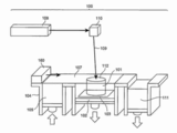
- FIG. 2 is a schematic view showing the configuration of the powder additive manufacturing apparatus 100 of the SLM method.
- the stage 102 is lowered by the thickness of one layer (for example, about 20 to 50 ⁇ m) of the modeling member 101 to be laminated.
- the alloy powder 105 is supplied from the powder supply container 104 onto the base plate 103 on the upper surface of the stage 102, and the alloy powder 105 is flattened by the recoater 160 to form a powder bed 107 (layered powder).
- the laser beam 109 output from the laser oscillator 108 is passed through the galvanometer mirror 110 to the unmelted powder on the base plate 103.
- 2D slice-shaped solidification layer 112 is formed by irradiating the surface to form a micro-melting pond and moving the micro-melting pond to sequentially melt and solidify.
- the unmelted powder is collected in the collection container 111. By repeating this operation and laminating, the modeling member 101 is manufactured.
- the modeling member 101 is manufactured integrally with the base plate 103, and is covered with unmelted powder. At the time of taking out, after the irradiation of the laser beam is completed and the powder and the modeling member 101 are sufficiently cooled, the unmelted powder is collected, and the modeling member 101 and the base plate 103 are taken out from the powder additive manufacturing device 100. After that, the modeling member 101 is cut from the base plate 103 to obtain the modeling member 101 (corresponding to the modeling member A).
- the matrix of the modeling member 101 had a structure in which fine columnar crystals (average width 50 ⁇ m or less) were forested along the stacking direction of the modeling member 101 (so-called quenching solidification structure).
- quenching solidification structure a structure in which fine columnar crystals (average width 50 ⁇ m or less) were forested along the stacking direction of the modeling member 101.
- microcell structures with an average diameter of 10 ⁇ m or less were formed inside the fine columnar crystals.
- the microcell structure refers to an elliptical or rectangular solidified structure that appears by electrolytic etching with oxalic acid or the like.
- FIG. 3 is a schematic view showing the configuration of the powder additive manufacturing apparatus 200 of the LMD method.
- the optical system is focused on the surface layer portion of the modeling member 303 to be laminated, and the alloy powder 105 is ejected and supplied from the powder supply container 201 toward the laser focal portion.
- the laser beam or electron beam 203 output from the laser oscillator 202 via the laser head portion 206 is modeled on the base plate 205.
- a solidification layer 112 is formed on the irradiation path by irradiating the member to form a micro-melting pond and moving the micro-melting pond to sequentially melt and solidify.
- the modeling member 101 (corresponding to the modeling member A) is manufactured.
- the molten portion can be formed on the surface layer portion by scanning the laser beam or the electron beam on the modeling member 303 without ejecting and supplying the alloy powder 105.
- FIG. 1 An example of aging heat treatment is shown in FIG.
- the above-mentioned modeling member 101 is heated and subjected to aging heat treatment to maintain it in a temperature range in which ultrafine particles are likely to increase, for example, in a temperature range of more than 500 ° C and less than 900 ° C.
- aging heat treatment above the operating temperature of the modeling member, it is possible to obtain a member that causes almost no decrease in hardness when used in a temperature range below the temperature of the aging heat treatment. Can be done.
- aging heat treatment For members that require wear resistance at high temperatures, it is preferable to perform aging heat treatment at a temperature higher than the temperature at which the modeling member is used. Further, when the surface treatment is applied to impart wear resistance, the surface treatment temperature is often high. In that case, it is preferable to perform aging heat treatment at a surface treatment temperature or higher.
- the temperature of the aging heat treatment for increasing the hardness of the laminated model is preferably 600 ° C. or higher and 850 ° C. or lower, and more preferably 650 ° C. or higher and 800 ° C. or lower.
- the holding time should be 0.5 hours or more and 24 hours or less. It is preferably set to 0.5 hours or more and 8 hours or less, and more preferably 1 hour or more and 8 hours or less. If it is 0.5 hours or more, the effect of improving the strength can be obtained, and if it is 24 hours or less, it is possible to suppress the formation of hexagonal precipitates that cause deterioration of corrosion resistance.
- nanoscale ultrafine particles having an average particle size of 50 nm or less can be generated in the microcell structure described later, and the strength can be improved.
- the cooling step after the aging heat treatment is not particularly limited, but if it is held for a long time in the vicinity of the aging heat treatment temperature, nanoscale ultrafine particles may be excessively generated. Cool to room temperature.
- FIG. 4 is an example, and the heat treatment pattern can be variously changed.
- the temperature raising process in the aging heat treatment for example, if the temperature rising rate is 5 ° C./min or more, the residence temperature in the intermediate temperature range where it is difficult to adjust the precipitation amount can be shortened, which is preferable. It is preferably 10 ° C./min or higher.
- the upper limit is not particularly limited, but is about 1000 ° C./min or less from the viewpoint of ensuring temperature uniformity in the modeling member 101, particularly prevention of generation of overheated parts.
- ultrafine particles are generated in the microcell structure having an average diameter of 10 ⁇ m or less. Its average particle size is 50 nm or less, which is smaller than the tiny particles in the parent phase crystal grains described below.
- the lower limit of the average particle size is not particularly limited, but is, for example, about 2 nm, preferably 3 nm, and more preferably 5 nm.
- the preferred upper limit is about 30 nm, more preferably 20 nm, and even more preferably 10 nm.
- the average particle size of the ultrafine particles is 2 nm or more and 50 nm or less, the hardness can be increased.
- ductility decreases when the average particle size of ultrafine particles exceeds 50 nm.
- the size of the ultrafine particles an image containing the ultrafine particles is acquired by a high-magnification observation means represented by a transmission electron microscopy or a high-resolution scanning electron microscopy, and the inscribed circle diameter of the ultrafine particles is obtained.
- the average value of the circumscribing circle diameters is used as the particle size of the ultrafine particles, and the average value of the particle sizes of 20 ultrafine particles is used as the average particle size.
- FIG. 5 shows an example of the fine structure of the alloy member (aging heat-treated material: M1-650AG) according to the present invention, which will be described later, and (a) and (b) are scanning electron microscope images (SEM images) and (c). (d) is a scanning transmission electron microscope image (STEM image).
- the alloy member of the present invention has a matrix structure 2 mainly composed of columnar crystals having a crystal grain size of 20 ⁇ m or more and 150 ⁇ m or less (average crystal grain size of 100 ⁇ m or less) ( Since it is difficult to distinguish in this figure, one tissue is shown by a broken line).
- the average crystal grain size is the average of 10 crystal grains measured by the cutting method using an SEM image with a magnification of 500 times. Further, although not shown in the SEM image of (a), a microcell structure having an average diameter of 10 ⁇ m or less is formed inside the tissue. For example, it can be said that the interval indicated by the arrow in the enlarged image of (b) indicates the diameter of the microcell structure. Then, in the SEM-EDS image of (b), the concentration of Ti was confirmed at the boundary portion 3 of the microcell structure shown by the white bright part.
- the brighter region shows the inside of the microstructure
- the boundary portion 3 of the microstructure is shown by a black line having a higher density than the inside. It has a dislocation 4 that is Therefore, by confirming the concentrated portion where black streaks are gathered more than the inside of the microstructure by the STEM image, it can be identified that the dislocation has a higher surface density than the inside of the tissue. Further, it was confirmed that a precipitate 5 made of an intermetallic compound was formed at the boundary portion 3 of another microcell structure. In the higher magnification (d) STEM image, ultrafine particles 6 having an average particle size of about 3 nm were confirmed.
- the element mapping image of this region by STEM-EDX is shown in the upper right of (d), and it was confirmed that the above-mentioned ultrafine particles 6 are particles in which Ni and Ti are concentrated.
- (e) is a schematic representation of the microstructure. As described above, this microstructure has a microcell structure in the crystal grains of the surface layer portion, and black streaky dislocations having a higher surface density than the inside of the microcell structure are formed at the boundary portion 3 of the microcell structure. Has 4. Further, it was found that the microcell structure was a structure in which ultrafine particles 6 were dispersed and precipitated.
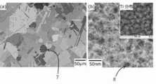
- FIG. 6 shows an example of the fine structure of the alloy member (solution treatment material: M1-S) related to the comparative example described later, in which (a) is a scanning electron microscope image (SEM image) and (b). Is a scanning transmission electron microscope image (STEM image).
- the alloy member M1 (without solution heat treatment and without aging heat treatment) of the comparative example is a parent phase crystal mainly composed of columnar crystals having a crystal grain size of 20 ⁇ m to 150 ⁇ m (average crystal grain size of 100 ⁇ m or less) as in FIG. 5 (a). It had a structure, and a microcell structure with an average diameter of 10 ⁇ m or less was formed inside. As shown in FIG.
- M1-S (with solution heat treatment and without aging heat treatment) is a matrix mainly composed of equiaxed crystals with a crystal grain size of 50 ⁇ m to 150 ⁇ m (average crystal grain size of 100 ⁇ m or less). It had a structure (crystal grain) 7. It was confirmed that the columnar crystals were recrystallized into equiaxed crystals by the solution heat treatment. Further, in M1-S, as shown in FIG. 6 (b), extremely small particles 8 having an average particle size of 20 to 30 nm were observed in the crystal grains of the matrix phase. The element mapping image by STEM-EDX is also shown in (b), and it was confirmed that the microparticles 8 are particles in which Ni and Ti are concentrated. In the alloy member M1, only the microcell structure having dislocations was observed, and no clear ultrafine particles having a particle size of 3 nm or more were observed.
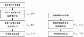
- the manufacturing method according to another embodiment of the present invention can be started by preparing the preliminarily obtained modeling member A.
- the modeling member A one obtained after the above-mentioned extraction step may be used, or one separately manufactured in advance may be used.
- the modeling member A is subjected to the following solution heat treatment to obtain a modeling member B having a matrix structure mainly composed of equiaxed crystals.
- the surface layer of the modeling member B is melted and solidified by a laser beam or an electron beam to form a new solidified layer.
- the solidified layer can be formed by scanning the laser beam or the electron beam on the modeling member B without ejecting and supplying the alloy powder.
- Such a remelting / solidifying step is carried out to obtain a remelting modeling member C.
- This remelt molding member C forms a melt-solidified structure containing a microcell structure having a diameter of 10 ⁇ m or less on the surface layer on a mother body having excellent corrosion resistance and mechanical properties.
- this manufacturing method may start from the preparation of the preliminarily obtained modeling member A, or the modeling member B having a matrix structure mainly composed of equiaxed crystals is subjected to solution heat treatment. You can also start by preparing in advance. As the modeling member B, one obtained after the solution heat treatment step may be used, or one separately manufactured in advance may be used.
- a surface layer addition molding process is performed on the modeling member B by subjecting it to a layered manufacturing method using a laser or an electron beam to form a new solidification layer by melting and solidifying on the surface layer portion, and the surface layer addition modeling member (modeling member D) is formed. obtain.
- the molding member D By directly subjecting the molding member D to aging heat treatment, it is possible to obtain an alloy member having more excellent tensile strength and ductility mechanical properties and improved hardness.
- the hardness of the surface layer of the second alloy member manufactured by the above remelting / solidifying step or the manufacturing method using the surface layer addition molding step is improved. That is, as shown in FIG. 9, a matrix structure mainly composed of equiaxed crystals having excellent toughness and ductility is arranged inside the alloy member 101a, and a microcell structure and the inside 101a of the alloy member are arranged on the surface layer portion 101b. It is possible to provide a structure in which ultrafine particles smaller than the ultrafine particles contained in the above coexist. As a result, as described above, the mechanical properties of tensile strength and ductility are more excellent, and in addition, the alloy member has improved hardness.
- the solution heat treatment will be described below.
- the holding temperature in the solution heat treatment shall be in the temperature range of 1080 ° C or higher and 1180 ° C or lower (1080 ° C to 1180 ° C). It is preferably 1100 ° C. or higher and 1140 ° C. or lower, and more preferably 1110 ° C. or higher and 1130 ° C. or lower.
- 1080 ° C or higher hexagonal precipitates that lead to embrittlement are precipitated and are difficult to remain.
- defects such as coarsening of crystal grain size and partial melting are less likely to occur.
- the holding time at the maximum temperature is preferably 0.5 hours or more and 24 hours or less, preferably 0.5 hours or more and 8 hours or less, and more preferably 1 hour or more and 4 hours or less.
- it is 0.5 hours or more, the formation of hexagonal precipitates in the modeling member 101 can be suppressed, and when it is 24 hours or less, the coarsening of the crystal grain size can be suppressed.
- the temperature range in which hexagonal precipitates are likely to occur (for example, from 800 ° C. to 1080 ° C.) is swift, and if the temperature rise rate is, for example, 5 ° C./min or more, hexagonal crystals It is preferable because the amount of precipitates of the above can be reduced before the heat treatment. It is preferably 10 ° C./min or higher.
- the upper limit is not particularly limited, but is about 1000 ° C./min from the viewpoint of ensuring temperature uniformity in the modeling member 101, particularly prevention of occurrence of overheated parts.
- the solid solution limit of the alloy is not clear, and extremely small particles having an average particle size of 100 nm or less are dispersed and precipitated on the alloy member which is the final product. Therefore, the heat treatment as described above is performed. Can be said to be a pseudo-solution heat treatment. However, in the present specification, these are included and simply referred to as solution heat treatment.
- a cooling step is performed on the modeling member after the solution heat treatment step.
- the cooling step it is preferable to cool at least the temperature range from the holding temperature to 800 ° C. at a cooling rate of 110 ° C./min or more and 2400 ° C./min or less in the heat treatment.
- the cooling rate is preferably 110 ° C./min or more and less than 600 ° C./min, and more preferably 200 ° C./min or more and less than 600 ° C./min. Cooling in this range can be adjusted by gas cooling using, for example, an inert gas such as nitrogen, argon or helium.
- the cooling rate is 600 ° C./min or more and 2400 ° C./min or less, more preferably 1000 ° C./min or more and 2000 ° C./min or less. Cooling in this range can be adjusted by, for example, liquid cooling using a salt bath, quenching oil, an aqueous polymer solution, or the like. If the cooling rate is less than 110 ° C./min (for example, furnace cooling or air cooling treatment), hexagonal precipitates are likely to be generated from the grain boundaries, which may cause a problem that corrosion resistance is lowered.
- a cooling rate exceeding 2400 ° C./min for example, immersion cooling in a water tank
- deformation of the modeling member due to temperature unevenness that occurs during rapid cooling may become a problem.
- a manufacturing method is appropriately selected, such as a laminated model body subjected to aging heat treatment or a laminated model body subjected to solution heat treatment and aging heat treatment, to obtain mechanical properties and wear resistance according to the application. be able to.
- the modeling member A and the modeling member B can be separately manufactured and prepared. Since the modeling member A and the modeling member B can be appropriately used according to the desired product and the production time, the production control can be rationalized and the production can be performed at low cost. Examples of applications are fluid machine impellers, injection molding machine screws, oil well drilling equipment and injection molding screws and cylinders, turbine wheels for generators, compressor impellers, chemical plant valves and joints, heat.
- Example 1 (Preparation of HEA powder P1 to P2)
- the raw materials were mixed according to the nominal composition shown in Table 1, and an alloy powder was produced from the molten metal by the vacuum gas atomizing method.
- the obtained alloy powder was classified by sieving and sorted so that the particle size was 10 ⁇ m or more and 53 ⁇ m or less and the average particle size (d50) was about 35 ⁇ m, and HEA powders P1 and P2 were prepared.
- the reason why the compositions of P1 and P2 were selected is that they were particularly excellent in mechanical properties related to strength and ductility in the preliminary study by the inventor.
- a powder having the composition disclosed in the above-mentioned International Publication No. 2019/031577 can also be used.
- the laser output during laminated molding was set to 300 W based on a preliminary study by the inventor, the laser scanning speed was set to 1000 mm / sec, and the scanning interval was set to 0.11 mm.
- the laminated thickness of each layer was set to about 0.04 mm.
- a modeling member M1 (corresponding to the modeling member A) was obtained.
- Various heat treatments were applied to the modeling member M1 to prepare each alloy member.
- the modeling member M1 was subjected to aging heat treatment as it was.
- a sample cooled with high-pressure nitrogen gas having a set pressure of 0.5 MPa was sampled using a vacuum furnace, heated at a heating rate of 10 ° C./min, held at 500 ° C. for 8 hours, and then cooled with M1-500AG. And said.
- the sample cooled with nitrogen gas was similarly cooled with M1-600AG, M1-650AG, M1-700AG, and M1-. It was set to 800AG and M1-900AG.
- a modeling member M2 (corresponding to modeling member A) was obtained through a laminated modeling step S30 and an extraction step S50 in the same manner as described above.
- the modeling member M2 was subjected to the aging heat treatment step S70 to prepare M2-500AG, M2-600AG, M2-650AG, M2-700AG, M2-800AG, and M2-900AG.
- M2-S (corresponding to modeling member B) was produced by performing only solution heat treatment on the modeling member M2.
- M1 (M2) -RM650AG ⁇ Making alloy member M1 (M2) -RM650AG>
- M1-S corresponding to the modeling member B
- a remelting / solidification step S60 for forming the solidified layer was performed to obtain a modeling member (corresponding to modeling member C).
- the temperature was raised at a heating rate of 10 ° C./min, held at 650 ° C. for 8 hours, cooled with high-pressure nitrogen gas having a set pressure of 0.5 MPa, and subjected to the aging heat treatment step S70.
- the remelting / solidifying step S60 and the aging heat treatment step S70 were carried out in the same manner as described above to prepare M2-RM650AG.
- ⁇ Making alloy member M1 (M2) -LD650AG> A laser beam powder overlay method (LMD method) using P1 powder was carried out on the previously obtained M1-S (corresponding to modeling member B), and a new molten / solidified layer was added to the surface layer of the M1-S (corresponding to the modeling member B).
- a surface layer addition molding step S65 in which only the layers were laminated and molded was performed to obtain a molding member (corresponding to the molding member D).
- the molding conditions were a laser output of 1.0 kW, a scanning speed of 1000 mm / min, a scanning interval of 2.0 mm, and a powder supply amount of 14 g / min.
- the matrix structure of the alloy members M1 and M2 without aging heat treatment has a structure in which fine columnar crystals having an average crystal grain size of 100 ⁇ m or less stand along the stacking direction of the laminated model (so-called local structure). It had a quenching solidification structure).
- the columnar crystal referred to here is defined as a crystal in which the ratio of the major axis length of the crystal grain to the minor axis length is 2 or more. Then, a microcell structure having a diameter of 10 ⁇ m or less was formed inside each crystal grain.
- M2-700AG, M2-800AG, M2-900AG the matrix structure is composed of columnar crystals and has a microcell structure, but when the aging heat treatment is 900 ° C, the microcell structure disappears and the inside of the crystal grains The ultrafine particles of are also over 50 nm.
- the microcell structure disappears although the ultrafine particles in the crystal grains are precipitated, and the crystal grains have a polygonal shape, etc. It had changed to an axial crystal. Furthermore, in the M1-RM650AG and M2-RM650AG, in which the surface layers of the alloy members M1-S and M2-S are remelted to provide a new melting / solidifying layer and further subjected to aging heat treatment, fine particles are precipitated inside. However, the microcell structure disappeared and became equiaxed crystals.
- the molten / solidified layer on the surface is columnar crystals and has a microcell structure, and ultrafine particles are also precipitated.
- M1-LD650AG and M2-LD650AG which were provided with a new molten / solidified layer by laminated molding on the alloy members M1-S and M2-S and further subjected to aging heat treatment.
- M1-LD650AG, M2-RM650AG, and M2-LD650AG very small particles with an average particle size of 100 nm or less are generated in the crystal grains.
- TEM and STEM-EDX Furthermore, it was confirmed by STEM-EDX that the Ni component and the Ti component of these extremely small particles were thicker than those of the parent phase crystal.
- test pieces obtained a tensile strength of 1100 MPa or more and a breaking elongation of 5% or more. Among them, it was confirmed that the test pieces of M1-650AG and M2-650AG had a tensile strength of 1500 MPa or more.
- the Vickers hardness (load: 4.9 N, indentation time: 10 seconds) was measured for the cross-section test pieces of each alloy member prepared above. In each case, 5 points in the plane were measured to obtain the average value, which is shown in Table 4.
- the hardness is based on the hardness of 550HV required for wear-resistant parts such as resource mining environments, and a hardness of 550HV or higher is judged as "pass” and a hardness of less than 550HV is judged as "fail”.
- 550HV is a value necessary for ensuring wear resistance, and is a value that can be sufficiently put into practical use in a normal environment.
- the hardness is measured separately for the built-up part or remelting part of the surface layer and the inside, and the hardness depends on the hardness of the surface layer where wear resistance is required. The pass / fail was judged.
- a immersion test piece (length 25 mm ⁇ width 25 mm ⁇ thickness 2 mm) for a 10% boiling sulfuric acid immersion test was collected from each alloy member produced above.
- the boiling sulfuric acid immersion test is a test that is additionally performed especially for members used in a strongly acidic atmosphere such as a resource mining environment or a chemical plant, and is performed in order to evaluate higher corrosion resistance.
- the immersion test was performed on each test piece with a test area of 14.5 cm 2 , test equipment: a glass flask connected with a glass backflow water-cooled condenser (capacity: 1000 mL), test solution: 10% aqueous sulfuric acid solution (surface area of the test piece).
- test temperature Determine the weight loss after immersion for 24 hours under boiling conditions , and use the alloy density (8.04 g / cm 3 ), for the corrosion rate (mm / year). It was used as an index.
- a corrosion rate of 5 mm / year or less in boiling sulfuric acid was judged as "pass”, and a corrosion rate of more than 5 mm / year was judged as "fail”.
- a case exceeding 5 mm / year was judged as "failed”, but it is a value that can be sufficiently put into practical use in a normal environment.
- the results of the above corrosion test are also shown in Table 4.
- Table 4 and Fig. 10 show the evaluation results and pass / fail judgment of each test piece.
- the alloy members M1 and M2 which are the samples not subjected to the heat treatment step, have a hardness of less than 550 HV and are not suitable for application to an environment requiring high wear resistance. It was also confirmed that the hardness of M1-S and M2-S, which had undergone only solution heat treatment, was similarly less than 550 HV. However, the tensile strength is 1100 MPa or more and the breaking elongation is 10% or more, so that it can be sufficiently put into practical use in applications and parts where high wear resistance is not required.
- the alloy members M1-500AG and M2-500AG basically show the same characteristics as M1 and M2, respectively, and since ultrafine particles do not precipitate, the change in hardness from M1 and M2 is small and less than 550HV. rice field.
- the alloy members M1-900AG and M2-900AG were rejected because the corrosion rate exceeded 5 mm / year. It is considered that this is because the ultrafine particles were transformed into hexagonal precipitates, which were coarser and had poor corrosion resistance, and became larger than 50 nm during the aging heat treatment at a high temperature.
- Fig. 10 shows the relationship between the aging heat treatment temperature and hardness. From the figure, it can be seen that the hardness is 550 HV or more when the aging temperature is 550 ° C or higher, and tends to be maximum near 800 ° C.
- remelt molding members M1-RM650AG, M2-RM650AG
- surface layer addition molding members M1-LD650AG, M2-LD650AG
- a new cured layer was obtained on the surface layer, and the inside was excellent in ductility. It maintained a structure consisting of axial crystals. It was confirmed that the inside of these members maintains ductility of 20% or more, and is particularly suitable for applications such as molds that require both surface hardness, ductility and toughness.
- the present invention is not limited to the specific configurations described.
- the alloy member disclosed in the present invention can be applied to corrosion-resistant and wear-resistant parts widely used in industrial fields, resource fields, chemical plants, mold members, and the like.
- Modeling member (surface layer), 200 ... Powder lamination Modeling equipment, 201 ... Powder supply container, 203 ... Laser beam or electron beam, 204 ... Table, 205 ... Vise, 206 ... Laser head, 303 ... Modeling member, S10 ... Raw material powder manufacturing process, S30 ... Laminated modeling process, S40 ... Solution heat treatment process, S50 ... Extraction process, S60 ... Remelt / solidification process, S65 ... Surface layer addition modeling process, S70 ... Aging heat treatment process
Landscapes
- Chemical & Material Sciences (AREA)
- Engineering & Computer Science (AREA)
- Materials Engineering (AREA)
- Mechanical Engineering (AREA)
- Metallurgy (AREA)
- Organic Chemistry (AREA)
- Manufacturing & Machinery (AREA)
- Physics & Mathematics (AREA)
- Thermal Sciences (AREA)
- General Engineering & Computer Science (AREA)
- Plasma & Fusion (AREA)
- Crystallography & Structural Chemistry (AREA)
- Powder Metallurgy (AREA)
Priority Applications (3)
| Application Number | Priority Date | Filing Date | Title |
|---|---|---|---|
| US17/908,529 US20230122004A1 (en) | 2020-03-03 | 2021-01-29 | Production method of alloy member, alloy member, and product using alloy member |
| EP21764385.7A EP4116013A4 (en) | 2020-03-03 | 2021-01-29 | METHOD FOR PRODUCING AN ALLOY ELEMENT, ALLOY ELEMENT AND PRODUCT COMPRISING THE ALLOY ELEMENT |
| JP2022505041A JP7173397B2 (ja) | 2020-03-03 | 2021-01-29 | 合金部材の製造方法、合金部材、および合金部材を用いた製造物 |
Applications Claiming Priority (2)
| Application Number | Priority Date | Filing Date | Title |
|---|---|---|---|
| JP2020-035862 | 2020-03-03 | ||
| JP2020035862 | 2020-03-03 |
Publications (1)
| Publication Number | Publication Date |
|---|---|
| WO2021176910A1 true WO2021176910A1 (ja) | 2021-09-10 |
Family
ID=77613851
Family Applications (1)
| Application Number | Title | Priority Date | Filing Date |
|---|---|---|---|
| PCT/JP2021/003382 Ceased WO2021176910A1 (ja) | 2020-03-03 | 2021-01-29 | 合金部材の製造方法、合金部材、および合金部材を用いた製造物 |
Country Status (4)
| Country | Link |
|---|---|
| US (1) | US20230122004A1 (https=) |
| EP (1) | EP4116013A4 (https=) |
| JP (1) | JP7173397B2 (https=) |
| WO (1) | WO2021176910A1 (https=) |
Cited By (3)
| Publication number | Priority date | Publication date | Assignee | Title |
|---|---|---|---|---|
| CN116103592A (zh) * | 2023-04-12 | 2023-05-12 | 北京中辰至刚科技有限公司 | 一种高熵合金的热处理方法 |
| CN116815077A (zh) * | 2023-08-30 | 2023-09-29 | 北京中辰至刚科技有限公司 | 一种基于TaHfNbZrTi系难熔高熵合金气淬时效热处理方法 |
| EP4242335A4 (en) * | 2020-11-04 | 2024-04-24 | Proterial, Ltd. | Alloy member manufacturing method, alloy member, and product using alloy member |
Families Citing this family (3)
| Publication number | Priority date | Publication date | Assignee | Title |
|---|---|---|---|---|
| CN116949338B (zh) * | 2023-07-18 | 2025-10-21 | 浙江绿色智行科创有限公司 | 甲醇喷油器、甲醇喷油器阀座的合金材料及其制备方法 |
| CN117464019A (zh) * | 2023-09-22 | 2024-01-30 | 华南理工大学 | 一种基于粉末形配的高熵合金粘结剂喷射3d打印与烧结成形方法 |
| CN119407198A (zh) * | 2024-11-08 | 2025-02-11 | 沈阳飞机工业(集团)有限公司 | 一种基于跨尺度协同界面强化的梯度金属增材制造方法 |
Citations (2)
| Publication number | Priority date | Publication date | Assignee | Title |
|---|---|---|---|---|
| WO2017138191A1 (ja) * | 2016-02-09 | 2017-08-17 | 株式会社日立製作所 | 合金部材、該合金部材の製造方法、および該合金部材を用いた製造物 |
| WO2019031577A1 (ja) | 2017-08-09 | 2019-02-14 | 日立金属株式会社 | 合金部材、該合金部材の製造方法、および該合金部材を用いた製造物 |
Family Cites Families (5)
| Publication number | Priority date | Publication date | Assignee | Title |
|---|---|---|---|---|
| WO2013098054A1 (en) * | 2011-12-28 | 2013-07-04 | Arcam Ab | Method and apparatus for detecting defects in freeform fabrication |
| CN106119835A (zh) * | 2016-07-28 | 2016-11-16 | 四川建筑职业技术学院 | 一种等轴晶高熵合金涂层及其制备方法 |
| JP6937491B2 (ja) | 2017-03-02 | 2021-09-22 | 株式会社日立製作所 | 合金部材、該合金部材の製造方法、および該合金部材を用いた製造物 |
| EP4032637A4 (en) * | 2019-09-20 | 2023-10-04 | Proterial, Ltd. | METHOD FOR PRODUCING ALLOY ELEMENT AND ALLOY ELEMENT |
| WO2022097652A1 (ja) * | 2020-11-04 | 2022-05-12 | 日立金属株式会社 | 合金部材の製造方法、合金部材、および合金部材を用いた製造物 |
-
2021
- 2021-01-29 WO PCT/JP2021/003382 patent/WO2021176910A1/ja not_active Ceased
- 2021-01-29 JP JP2022505041A patent/JP7173397B2/ja active Active
- 2021-01-29 US US17/908,529 patent/US20230122004A1/en active Pending
- 2021-01-29 EP EP21764385.7A patent/EP4116013A4/en active Pending
Patent Citations (2)
| Publication number | Priority date | Publication date | Assignee | Title |
|---|---|---|---|---|
| WO2017138191A1 (ja) * | 2016-02-09 | 2017-08-17 | 株式会社日立製作所 | 合金部材、該合金部材の製造方法、および該合金部材を用いた製造物 |
| WO2019031577A1 (ja) | 2017-08-09 | 2019-02-14 | 日立金属株式会社 | 合金部材、該合金部材の製造方法、および該合金部材を用いた製造物 |
Cited By (4)
| Publication number | Priority date | Publication date | Assignee | Title |
|---|---|---|---|---|
| EP4242335A4 (en) * | 2020-11-04 | 2024-04-24 | Proterial, Ltd. | Alloy member manufacturing method, alloy member, and product using alloy member |
| CN116103592A (zh) * | 2023-04-12 | 2023-05-12 | 北京中辰至刚科技有限公司 | 一种高熵合金的热处理方法 |
| CN116815077A (zh) * | 2023-08-30 | 2023-09-29 | 北京中辰至刚科技有限公司 | 一种基于TaHfNbZrTi系难熔高熵合金气淬时效热处理方法 |
| CN116815077B (zh) * | 2023-08-30 | 2023-11-21 | 北京中辰至刚科技有限公司 | 一种基于TaHfNbZrTi系难熔高熵合金气淬时效热处理方法 |
Also Published As
| Publication number | Publication date |
|---|---|
| JP7173397B2 (ja) | 2022-11-16 |
| EP4116013A4 (en) | 2023-10-11 |
| US20230122004A1 (en) | 2023-04-20 |
| JPWO2021176910A1 (https=) | 2021-09-10 |
| EP4116013A1 (en) | 2023-01-11 |
Similar Documents
| Publication | Publication Date | Title |
|---|---|---|
| JP7173397B2 (ja) | 合金部材の製造方法、合金部材、および合金部材を用いた製造物 | |
| Brenne et al. | Microstructural design of Ni-base alloys for high-temperature applications: impact of heat treatment on microstructure and mechanical properties after selective laser melting | |
| JP6835139B2 (ja) | 合金部材の製造方法 | |
| Vishwakarma et al. | Effect of build orientation on microstructure and tensile behaviour of selectively laser melted M300 maraging steel | |
| Qi et al. | Studies of standard heat treatment effects on microstructure and mechanical properties of laser net shape manufactured INCONEL 718 | |
| JP6690789B2 (ja) | 合金材、該合金材を用いた製造物、および該製造物を有する流体機械 | |
| JP6690790B2 (ja) | 合金材、該合金材の製造方法、該合金材を用いた製造物、および該製造物を有する流体機械 | |
| TWI799782B (zh) | 鈷基合金構造體及其製造方法 | |
| JP7248196B2 (ja) | 合金部材の製造方法、合金部材、および合金部材を用いた製造物 | |
| KR101909152B1 (ko) | 열 저항 알루미늄 기본 합금 및 제조 방법 | |
| Yan et al. | Laser powder bed fusion and post processing of alloy 22 | |
| JP7156474B2 (ja) | 合金部材の製造方法 | |
| Tu et al. | Microstructure and mechanical properties of Mg-12Gd-3Y-0.4 Zr magnesium alloy with layered heterogeneous microstructure fabricated by wire arc additive manufacturing | |
| JP7327704B2 (ja) | 合金材、合金材を用いた合金製造物、及び合金製造物を備える機械装置 | |
| JP2024071286A (ja) | Ni基合金造形物の製造方法、およびNi基合金造形物 | |
| JP7761177B2 (ja) | 付加製造用Ni基合金粉末及びNi基合金造形物の製造方法 | |
| JP7677529B2 (ja) | 積層造形体からなるNi-Cr合金部材、Ni-Cr合金部材の製造方法、およびNi-Cr合金部材を用いた製造物 | |
| Farhang | ENHANCING MICROSTRUCTURE, COMPOSITION HOMOGENEITY, AND MECHANICAL PROPERTIES IN LASER POWDER BED FUSED METALLIC ALLOYS: DESIGN, FABRICATION, AND EVALUATION | |
| WO2022071378A1 (ja) | 合金材料、該合金材料を用いた合金製造物、および該合金製造物を有する機械装置 | |
| JP2023045935A (ja) | Fe-Al系合金、Fe-Al系合金部材、Fe-Al系合金粉末およびFe-Al系合金の製造方法 | |
| Schloetter | Effect of Composition and Build Direction on Additively Manufactured Hastelloy X Alloys | |
| Spitzer et al. | Effect of Composition and Build Direction on Additively Manufactured Hastelloy X Alloys | |
| Pramod et al. | Improved tensile strength and ductility of IN718 via functionally gradient structure processed through Laser Powder Bed Fusion (L-PBF) technique. | |
| Vrancken et al. | AM: Characterisation and Post Treatment: Adapted Heat Treatment of Selective Laser Melted Materials | |
| Wu et al. | Some recent work on alloy and process development of Ti and TiAl-based alloys |
Legal Events
| Date | Code | Title | Description |
|---|---|---|---|
| 121 | Ep: the epo has been informed by wipo that ep was designated in this application |
Ref document number: 21764385 Country of ref document: EP Kind code of ref document: A1 |
|
| ENP | Entry into the national phase |
Ref document number: 2022505041 Country of ref document: JP Kind code of ref document: A |
|
| NENP | Non-entry into the national phase |
Ref country code: DE |
|
| ENP | Entry into the national phase |
Ref document number: 2021764385 Country of ref document: EP Effective date: 20221004 |