WO2021176545A1 - 湿度センサ - Google Patents
湿度センサ Download PDFInfo
- Publication number
- WO2021176545A1 WO2021176545A1 PCT/JP2020/008814 JP2020008814W WO2021176545A1 WO 2021176545 A1 WO2021176545 A1 WO 2021176545A1 JP 2020008814 W JP2020008814 W JP 2020008814W WO 2021176545 A1 WO2021176545 A1 WO 2021176545A1
- Authority
- WO
- WIPO (PCT)
- Prior art keywords
- sound wave
- wave element
- sound
- humidity
- distance
- Prior art date
- Legal status (The legal status is an assumption and is not a legal conclusion. Google has not performed a legal analysis and makes no representation as to the accuracy of the status listed.)
- Ceased
Links
Images

Classifications
-
- G—PHYSICS
- G01—MEASURING; TESTING
- G01N—INVESTIGATING OR ANALYSING MATERIALS BY DETERMINING THEIR CHEMICAL OR PHYSICAL PROPERTIES
- G01N29/00—Investigating or analysing materials by the use of ultrasonic, sonic or infrasonic waves; Visualisation of the interior of objects by transmitting ultrasonic or sonic waves through the object
- G01N29/02—Analysing fluids
-
- G—PHYSICS
- G01—MEASURING; TESTING
- G01N—INVESTIGATING OR ANALYSING MATERIALS BY DETERMINING THEIR CHEMICAL OR PHYSICAL PROPERTIES
- G01N29/00—Investigating or analysing materials by the use of ultrasonic, sonic or infrasonic waves; Visualisation of the interior of objects by transmitting ultrasonic or sonic waves through the object
- G01N29/22—Details, e.g. general constructional or apparatus details
- G01N29/24—Probes
Definitions
- This disclosure relates to a humidity sensor that measures the humidity in the air.
- psychrometers and hair hygrometers have been widely used as measuring instruments for humidity in the air.
- a dew point detection sensor a thermista humidity sensor, a lithium chloride humidity sensor, a ceramic humidity sensor, a polymer film humidity sensor, and the like have been proposed.
- the humidity measuring device described in Patent Document 1 has a pair of vibrators arranged so as to face each other while maintaining a certain distance. One oscillator emits ultrasonic waves, and the other oscillator receives the ultrasonic waves. Then, the humidity measuring device obtains the humidity in the air by obtaining the change in the sound velocity or the attenuation coefficient of the ultrasonic wave based on the reception result of the ultrasonic wave.
- the humidity measuring device described in Patent Document 1 can measure only the humidity in the vicinity of a pair of oscillators.
- the distance between the transmitting side vibrator and the receiving side vibrator in the space is long. Need to be installed. In that case, the sound wave transmitted from the transmitting side vibrator is attenuated in space before reaching the receiving side vibrator. Therefore, the signal level of the received signal of the oscillator on the receiving side becomes weak. As a result, there is a problem that the S / N of the received signal is lowered and it is difficult to measure the humidity.
- the present disclosure has been made to solve the above-mentioned problems, and by suppressing the decrease in S / N of the received signal, the accuracy of humidity measurement can be improved regardless of the size of the space.
- the purpose is to obtain a humidity sensor.
- the humidity sensor includes a first sound wave element that transmits and receives sound waves, a second sound wave element that transmits sound waves, a drive unit that drives the first sound wave element and the second sound wave element, and the above.
- the first sound wave element is provided with a detection unit that obtains humidity based on the reception result of the sound wave of the first sound wave element, and the first sound wave element and the second sound wave element are arranged side by side on a straight line parallel to the reflection surface.
- the 1-sound wave element receives the interference wave of the sound wave transmitted from the first sound wave element and the second sound wave element.
- the humidity sensor According to the humidity sensor according to the present disclosure, it is possible to improve the accuracy of humidity measurement regardless of the size of the space by suppressing the decrease in S / N of the received signal.
- FIG. 1 It is a side sectional view which shows typically the structure of the air conditioner 1 which concerns on Embodiment 1.
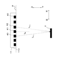
- FIG. It is a side sectional view which shows the structure of the humidity sensor 11 which concerns on Embodiment 1, and the relationship between a humidity sensor 11 and a reflection surface 4.
- FIG. It is a figure which shows the arrangement relationship between the sound wave element 12 and 13 and the reflection surface 4 in the humidity sensor 11 which concerns on Embodiment 1.
- FIG. It is a figure which shows the experimental result of Experiment 1. It is a figure which shows the relationship between the square integral value of an output voltage, and relative humidity. It is a figure which shows the experimental result of Experiment 2.
- It is a side sectional view which shows typically the structure of the air conditioner 1 which concerns on Embodiment 2.
- FIG. 1 It is a side sectional view which shows typically the structure of the air conditioner 1 which concerns on Embodiment 1.
- FIG. 1 It is a block diagram which shows the structure of the controller 16 of the humidity sensor 11 which concerns on Embodiment 2.
- FIG. It is a side sectional view which shows typically the structure of the air conditioner 1 which concerns on Embodiment 4.
- Embodiment 1 the air conditioner 1 and the humidity sensor 11 according to the first embodiment will be described with reference to the drawings.
- FIG. 1 is a side sectional view schematically showing the configuration of the air conditioner 1 according to the first embodiment.
- FIG. 1 shows a state in which the air conditioner 1 is installed in the room 2.
- Room 2 is an office space for business use or an indoor space of a general house.
- Room 2 is, for example, a rectangular parallelepiped space.
- Room 2 is provided with a ceiling 3.
- the ceiling 3 is provided with an installation hole 3a for installing the air conditioner 1.
- the installation hole 3a is a recess formed by hollowing out a part of the ceiling 3.
- the air conditioner 1 is embedded and fixed in the installation hole 3a.
- the position of the lower surface of the air conditioner 1 in the height direction coincides with the position of the ceiling 3 in the height direction.
- the straight line distance between the floor surface 39 of the room 2 and the ceiling 3 is 2 m or more. Therefore, the linear distance between the lower surface of the air conditioner 1 and the floor surface 39 of the room 2 is also 2 m or more.
- the vertical direction is referred to as a height direction.
- the vertical direction is, for example, the vertical direction.
- the reflective surface 4 is fixed to one surface of the room 2.
- the reflective surface 4 is installed on the floor surface 39 or the wall surface 38 of the room 2.
- the reflective surface 4 has a smooth surface, and the material is, for example, a metal plate or a resin plate.
- the floor surface 39 and the wall surface 38 of the room 2 have smooth surfaces, and the materials are, for example, a metal plate, a resin plate, and a wooden plate.
- the ceiling 3 of the room 2 also has a smooth surface.
- the air conditioner 1 is, for example, a package type air conditioner.
- the present invention is not limited to this case, and the air conditioner 1 may be a general air conditioner such as a cassette type air conditioner, a room air conditioner, or an outside air processing unit.
- the air conditioner 1 has a symmetrical configuration.
- the white arrow indicates the direction of air flow.
- the air conditioner 1 is provided with a suction port 5, a filter 6, a fan 7, two heat exchangers 8, an outlet 9, and two humidifying elements 10.
- the air conditioner 1 has a cooling function, a heating function, and a humidifying function.
- the air conditioner 1 may not have a humidifying function.
- the suction port 5 is provided on the lower surface of the air conditioner 1.
- the suction port 5 is arranged so as to face the indoor space of the room 2.
- the suction port 5 faces, for example, the floor surface 39 of the room 2. Air is sucked into the air conditioner 1 from the suction port 5.
- the air outlets 9 are arranged on the left and right sides of the suction port 5. Alternatively, the air outlet 9 is arranged so as to surround the suction port 5 in a bottom view.
- the bottom view means a case where the air conditioner 1 is looked up from the floor surface 39 side.
- the air outlet 9 is arranged so as to face the indoor space of the room 2.
- the air outlet 9 faces, for example, the floor surface 39 of the room 2.
- the air in the air conditioner 1 is blown out from the air outlet 9 toward the indoor space of the room 2.
- a wind direction plate may be provided at the air outlet 9 so that the wind direction of the air blown from the air outlet 9 can be changed.
- the fan 7 is arranged above the suction port 5.
- the fan 7 and the suction port 5 are separated from each other.
- a filter 6 is arranged between the fan 7 and the suction port 5.
- the fan 7 is, for example, a propeller fan. As the fan 7 rotates, air is sucked in from the suction port 5 and the air is discharged from the air outlet 9. Therefore, in the air flow path, the suction port 5 is on the upstream side and the air outlet 9 is on the downstream side. In this way, the fan 7 sends air to the heat exchanger 8.
- the heat exchangers 8 face each other.
- a fan 7 is arranged between the heat exchangers 8.
- Each of the heat exchangers 8 is arranged on the downstream side of the fan 7 in the air flow path.
- the heat exchanger 8 has a front surface 8a and a back surface 8b.
- the front surface 8a is arranged on the fan 7 side, and the back surface 8b is arranged on the air outlet 9 side. As shown in FIG. 1, the front surface 8a and the back surface 8b are arranged so that their main surfaces are parallel to each other in the vertical direction.
- the rotation of the fan 7 causes air to flow in from the front surface 8a and air to flow out from the back surface 8b. Therefore, in the air flow path, the front surface 8a is the upstream portion and the back surface 8b is the downstream portion.
- the heat exchanger 8 may be arranged so as to be inclined in the vertical direction so that the lower end portion of the heat exchanger 8 is the upstream portion and the upper end portion of the heat exchanger 8 is the downstream portion.
- the heat exchanger 8 is, for example, a fin and tube type heat exchanger.
- the heat exchanger 8 is provided with a plurality of heat transfer tubes through which the refrigerant flows.
- the heat exchanger 8 exchanges heat between the air sent by the fan 7 and the refrigerant flowing inside the heat transfer tube.
- the heat exchanger 8 heats or cools the air by the heat exchange. As a result, the room 2 is heated or cooled.
- the filter 6 is arranged between the suction port 5 and the heat exchanger 8 in the air flow path.
- the filter 6 removes dust from the air sucked from the suction port 5.
- the air from which the dust has been removed flows into the heat exchanger 8 by the rotation of the fan 7.
- Each of the humidifying elements 10 is arranged along the left and right heat exchangers 8. Therefore, of the two humidifying elements 10, one is arranged on the left side of the air conditioner 1 and the other is arranged on the right side. In the example of FIG. 1, the humidifying element 10 is arranged between the heat exchanger 8 and the air outlet 9. Each of the humidifying elements 10 is formed, for example, by arranging a plurality of plate-shaped members in parallel at regular intervals.
- the material of the humidifying element 10 is, for example, porous or fibrous paper or resin, and a filter-like material thereof is used.
- the length of the humidifying element 10 in the longitudinal direction is substantially the same as the length in the longitudinal direction of the heat exchanger 8.
- all the air flowing out of the heat exchanger 8 flows into the humidifying element 10.
- the air is uniformly humidified as a whole.
- a supply source (not shown) for supplying water is arranged above the humidifying element 10.
- the humidifying element 10 When water is supplied to the humidifying element 10 from the supply source, the humidifying element 10 is immersed in water. When air passes through the humidifying element 10 in that state, water volatilizes from the humidifying element 10 to humidify the air.
- Both tap water and industrial water can be used as the water, but it is desirable that the water has a small amount of scale components that cause sediments, such as calcium, magnesium, and silica.
- the air conditioner 1 when the fan 7 is driven, air is sucked from the suction port 5, and the air passes through the filter 6 to remove dust. After that, the air is cooled or heated by passing through the heat exchanger 8. The air cooled or heated by the heat exchanger 8 is humidified by the humidifying element 10. The humidified air is blown out from the outlet 9 into the room 2.
- the humidification operation may or may not be performed during the cooling operation or the heating operation. Alternatively, any one of the cooling operation, the heating operation, and the humidification operation may be performed independently. The user can freely select a desired air conditioner 1 from the cooling operation, the heating operation, and the humidifying operation by setting the operation mode.
- a humidity sensor 11 is provided.
- the humidity sensor 11 is composed of a plurality of sensor units 11A and 11B.
- the sensor units 11A and 11B of the humidity sensor 11 may be built in the air conditioner 1 or may be provided outside the air conditioner 1.
- the humidity sensor 11 may be a component of the air conditioner 1 or may be a device different from the air conditioner 1.
- each sensor unit 11A and 11B of the humidity sensor 11 is arranged in the lower part of the air conditioner 1.
- the sensor units 11A and 11B are arranged on the left and right sides of the suction port 5.
- the sensor units 11A and 11B are arranged between the suction port 5 and the air outlet 9, for example, as shown in FIG.
- the sensor units 11A and 11B are arranged at positions symmetrical with respect to the center of the suction port 5 in the left-right direction. That is, the distance from the center of the suction port 5 to the sensor unit 11A on the left side is D1, and the distance from the center of the suction port 5 to the sensor unit 11B on the right side is D2. At this time, the distance D1 and the distance D2 are equivalent.
- the electric parts and the electronic parts provided inside are collectively sealed with a resin, or these parts are housed in one casing.
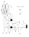
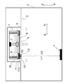
- FIG. 2 is a side sectional view showing the configuration of the humidity sensor 11 according to the first embodiment and the relationship between the humidity sensor 11 and the reflecting surface 4.
- the humidity sensor 11 is composed of a sensor unit 11A on the left side, a sensor unit 11B on the right side, and a controller 16.
- the sensor unit 11A is provided with a sound wave element 12, and the sensor unit 11B is provided with a sound wave element 13.
- the sound wave elements 12 and 13 emit sound waves, respectively.
- the sound wave elements 12 and 13 emit, for example, sound waves having a frequency of 20 kHz or more, that is, ultrasonic waves. In the following, a case where the sound wave elements 12 and 13 emit ultrasonic waves will be described as an example.
- the sound wave elements 12 and 13 have piezoelectric ceramics.
- the sound wave elements 12 and 13 have a mechanism of emitting ultrasonic waves by applying a voltage to the piezoelectric ceramics.
- Piezoelectric ceramics can not only transmit ultrasonic waves but also receive ultrasonic waves.
- Piezoelectric ceramics can receive ultrasonic waves in the air and convert the received ultrasonic waves into a voltage. Therefore, when the sound wave elements 12 and 13 have the piezoelectric ceramic, the sound wave elements 12 and 13 can transmit and receive ultrasonic waves.
- the sound wave elements 12 and 13 are arranged in a row on a straight line P. Specifically, the ultrasonic emission ports of the sound wave elements 12 and 13 are arranged in a row on a straight line P.
- the straight line P is parallel to the main surface of the reflecting surface 4.
- the sound wave element 12 transmits ultrasonic waves as a transmission wave 17.
- the sound wave element 13 transmits ultrasonic waves as a transmission wave 18.
- the transmitted wave 17 and the transmitted wave 18 are reflected by the reflecting surface 4 to become a reflected wave.
- the reflected wave is received by the sound wave element 12 as a received wave 19.
- the controller 16 has a detection unit 35, a drive unit 36, and a storage unit 37.
- the detection unit 35 detects the humidity of the room 2 based on the reception result of the sound wave element 12.
- the drive unit 36 drives the sound wave elements 12 and 13.
- the sound wave elements 12 and 13 are electrically connected to the drive unit 36 via the electric wire 14, respectively.
- the drive unit 36 drives the sound wave elements 12 and 13 by applying a pulse wave to the sound wave elements 12 and 13.
- the sound wave elements 12 and 13 emit transmitted waves 17 and 18, respectively, based on the pulse wave.
- the sound wave element 12 is electrically connected to the detection unit 35 via the electric wire 15.
- the detection unit 35 includes an AD converter 35a that converts the analog signal into a digital signal.
- the AD converter 35a performs AD conversion on the voltage output from the sound wave element 12 to obtain a digital signal.
- the detection unit 35 analyzes the waveform of the digital signal to obtain the humidity.
- the sampling frequency of the detection unit 35 is 2.4 MHz, and the resolution is 12 bits.
- the sampling frequency is preferably twice or more the pulse frequency of the pulse wave applied to the sound wave elements 12 and 13 by the drive unit 36, but here it is eight times.
- the controller 16 is composed of a processing circuit. Therefore, each function of the detection unit 35 and the drive unit 36 of the controller 16 is realized by the processing circuit.
- the processing circuit is composed of dedicated hardware or a processor.
- the dedicated hardware is, for example, an ASIC (Application Specific Integrated Circuit) or an FPGA (Field Programmable Gate Array).
- the processor executes a program stored in memory.
- the storage unit 37 of the controller 16 is composed of a memory.
- the memory is a non-volatile or volatile semiconductor memory such as RAM (RandomAccessMemory), ROM (ReadOnlyMemory), flash memory, EPROM (ErasableProgrammableROM), or a disk such as a magnetic disk, flexible disk, or optical disk. be.
- the distance between the sensor units 11A and 11B and the reflecting surface 4 may be arbitrary, but if the distance is too long, the ultrasonic waves will be attenuated and will not reach the reflecting surface 4.
- the frequency of the ultrasonic waves is set to 40 kHz as the frequency for the ultrasonic waves to reach up to 10 m.
- the frequency of the ultrasonic wave is not limited to this, and may be appropriately determined according to the size or characteristics of the room 2.
- FIG. 2 shows an example in which the sound wave element 12 receives ultrasonic waves, but the present invention is not limited to this, and the sound wave element 13 may receive ultrasonic waves.
- the sound wave element 13 is connected to the detection unit 35 via the electric wire 15. Both the sound wave elements 12 and 13 may be connected to the detection unit 35 via the electric wire 15, or one of the receiving sides may be connected to the detection unit 35 via the electric wire 15. May be good.
- the first sound wave element for transmitting and receiving sound waves and the second sound wave element for transmitting sound waves are provided.
- the sound wave element 12 is a first sound wave element and the sound wave element 13 is a second sound wave element will be described.
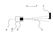
- FIG. 3 is a diagram showing an arrangement relationship between the sound wave elements 12 and 13 and the reflecting surface 4 in the humidity sensor 11 according to the first embodiment.
- the sensor unit 11A is shown as a representative for the sake of simplification of the figure.
- the directivity angle of the half width of the sound wave element 12 is defined as ⁇ .
- the reflecting surface 4 is installed so that the sound wave element 12 and the reflecting surface 4 face each other.
- the normal line from the sound wave element 12 and the reflecting surface 4 are made to intersect, and a part of the range of the directivity angle ⁇ is made to overlap a part of the reflecting surface 4.
- the reflective surface 4 may be fixed or movable.
- the directivity angle ⁇ of the half-value width of the sound wave element 12 is the width of the wavelength at which the relative radiant intensity becomes 50% of the peak value in the spectral distribution of the ultrasonic output from the sound wave element 12.
- the full width at half maximum is the full width at half maximum.
- the normal line from the sound wave element 12 is the radiation direction of the ultrasonic wave, and is a line passing through the center of the circumferential direction of the directivity angle ⁇ .
- the drive unit 36 applies a pulse wave having a frequency of 40 kHz to the sound wave elements 12 and 13.
- the sound wave elements 12 and 13 generate ultrasonic waves having a frequency of 40 kHz.
- the method of transmitting ultrasonic waves is not limited to the application of pulse waves by the driving unit 36, and the driving unit 36 may apply continuous waves such as AC to the sound wave elements 12 and 13.
- the pulse width may be arbitrary, but if it is too long, detection becomes difficult, so 1 to 5 times the wavelength is appropriate.
- the resolution tends to improve as the number of pulses increases, but on the other hand, the influence of the reverberant sound also increases, so about 1 to 100 pulses is appropriate.
- the ultrasonic wave transmission time is appropriately in the range of 0.01 to 1 millisecond.
- the ultrasonic waves generated from the sound wave elements 12 and 13 reach the reflecting surface 4 as the transmitted waves 17 and 18 indicated by the arrows, respectively. After that, the transmitted waves 17 and 18 are reflected by the reflecting surface 4 and reach the sound wave element 12 as the received wave 19. At that time, the interference wave 20 is generated.
- the solid line indicates the range in which the ultrasonic waves are overlapped and strengthened, and the broken line indicates the range in which the ultrasonic waves cancel each other out and mute. When this solid line portion overlaps the position of the sound wave element 12, the overlapped ultrasonic waves are detected by the sound wave element 12.
- the sound wave element 12 receives the interference wave 20 of the transmission waves 17 and 18 transmitted from the sound wave elements 12 and 13.
- the sound wave element 12 In order to make it easier for the sound wave element 12 to detect the interference wave 20, it is necessary to create a condition in which the ultrasonic waves are intensified. Therefore, in the first embodiment, attention is paid to the positional relationship between the sound wave element 12 and the sound wave element 13.
- a specific description will be given.
- the distance between the sound wave element 12 and the reflecting surface 4 is defined as the first distance L1
- the distance between the sound wave element 13 and the reflecting surface 4 is defined as the second distance L2.
- n is an integer and the following equation (1) holds for the difference (L1-L2) between the first distance L1 and the second distance L2
- the sound wave element 12 and the sound wave element 13 The emitted ultrasonic waves intensify each other. That is, when the difference in distance (L1-L2) becomes an integral multiple of the wavelength ⁇ , the ultrasonic waves emitted from the sound wave element 12 and the sound wave element 13 intensify each other.
- the distance difference (L1-L2) is 85.8 mm, which is 10 times the wavelength of 8.58 mm, and the ultrasonic waves are strengthened.
- the distance D3 between the sound wave element 12 and the sound wave element 13 as is clear from FIG. 2, the first distance L1, the second distance L2, and the distance D3 have the second distance L2 as the hypotenuse. Consists of a right triangle. Therefore, the distance D3 can be approximately calculated to be 0.930 m. From this, when the distance D3 between the sound wave element 12 and the sound wave element 13 is set to 0.930 m, the received wave 19 is strengthened.
- the distance D3 is the distance between the center of the outlet of the sound wave element 12 and the center of the outlet of the sound wave element 13.
- the sound wave element 12 and the sound wave element 13 are installed so that the difference (L1-L2) between the first distance L1 and the second distance L2 is an integral multiple of the wavelength ⁇ . This makes it easier for the sound wave element 12 to detect the interference wave 20.
- the sound wave element 12 converts the received ultrasonic wave into a voltage and outputs it.
- the output of the sound wave element 12 is referred to as a voltage output.
- the ultrasonic wave received by the sound wave element 12 includes at least one of a component derived from the transmitted wave 17 transmitted by the sound wave element 12 itself, a component derived from the received wave 19, and a component derived from the interference wave 20. Is included.
- the voltage output from the sound wave element 12 is transmitted to the detection unit 35 via the electric wire 15.
- the AD converter 35a of the detection unit 35 converts the voltage output into a digital signal by performing AD conversion on the voltage output from the sound wave element 12.
- the detection unit 35 calculates and outputs the relative humidity based on the voltage output converted into the digital signal.
- the relative humidity becomes the humidity of the room 2 detected by the humidity sensor 11.
- a specific calculation process in the detection unit 35 will be shown.
- Experiment 1 An example of the experimental results is shown below. Hereinafter, the experiment will be referred to as Experiment 1.
- the experiment was conducted in a constant temperature and humidity chamber as a space in which the indoor conditions of the room 2 shown in FIG. 1 were reduced to a size of about 1/10.
- L1 was set to 50 cm and L2 was set to 50.858 cm.
- the temperature was 22 ° C. and the relative humidity was changed to 30, 40, 50, 60, 70, 80 and 90%.
- the number of pulses applied to the sound wave element 12 was 20. Therefore, the number of transmitted waves 17 transmitted by the sound wave element 12 is 20.
- the change in the voltage output from the sound wave element 12 at this time was investigated.
- the voltage output from the sound wave element 12 was converted into a digital signal by the detection unit 35, and thereafter analyzed as discrete data. Further, in Experiment 1, only the sound wave element 12 transmitted the transmitted wave 17, and the sound wave element 13 did not transmit the transmitted wave 18. Further, the reflected wave from the reflecting surface 4 was received by the sound wave element 12 as a received wave 19.
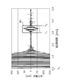
- FIG. 4 is a diagram showing the experimental results of Experiment 1.
- FIG. 4 shows the time change of the waveform of the output voltage from the sound wave element 12.
- the horizontal axis represents time and the vertical axis represents the output voltage of the sound wave element 12.
- the elapsed time of 0 ms indicates the time T 0 when the ultrasonic wave is transmitted from the sound wave element 12.
- the output voltage from the elapsed time of 0 ms to the elapsed time of 1.5 ms is not derived from the received wave 19 or the interference wave 20, but is derived from the transmitted wave 17 transmitted by the sound wave element 12.
- the first distance L1 is 50 cm, and the speed of sound is 343 m / s.
- the total number of pulse waves applied to the sound wave element 12 is 20. Therefore, the sound wave element 12 transmits 20 transmitted waves 17 according to those pulse waves. Out of 20 of the transmitted wave 17, reflected waves of the transmitted wave 17 transmitted to the first, as a received wave 19 is received at time T 1. Thereafter, ultrasonic element 12, during the period from the time T 1 to time T 2, 2, third, the reflected wave of the transmission wave 17 sent to ... sequentially receives as the reception wave 19.
- the method of determining the time T 2 will be described.
- the output voltage in the range from time T 1 to time T 2 is surrounded by a frame R1.
- the range indicated by the frame R1 is the output voltage derived from the received wave 19 and the interference wave 20.
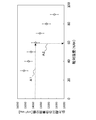
- FIG. 5 shows the result of calculating the square-integrable value of the output voltage by squaring the output voltage and integrating it in the range of 2.9 ms to 3.4 ms.
- FIG. 5 is a diagram showing the relationship between the square-integrable value of the output voltage and the relative humidity.
- the horizontal axis represents relative humidity and the vertical axis represents the square-integrable integrated value of the output voltage.
- Experiment 1 is repeated 10 times, a simple average value of each value is calculated, and the range of variation is indicated by an error bar. As shown in FIG.
- the square-integrable value of the output voltage is the highest when the relative humidity is 30%, and the square-integrable value of the output voltage decreases substantially linearly as the relative humidity increases.
- Moisture in the air has the property of scattering sound waves, and high relative humidity means that it contains a large amount of moisture in the air. Becomes smaller.
- the data table that defines the relationship between the output voltage of the sound wave element 12 and the relative humidity is stored in advance in the storage unit 37 of the controller 16.
- the data table defines, for example, the relationship between the square-integrable integral value of the output voltage of the sound wave element 12 and the relative humidity as the relationship.
- a method of generating a data table will be described.
- the data table has the relationship shown in FIG. 5 obtained for each indoor condition as data.
- the detection unit 35 obtains the relative humidity based on the square-integrable value of the output voltage of the sound wave element 12. For example, detector 35, when the square integral value of the output voltage of the ultrasonic element 12 was 13800mV 2 ⁇ ms, as indicated by arrows A1 and A2 in FIG. 5, from the data table, square integrated value 13800mV 2 ⁇ ms The relative humidity corresponding to can be obtained. In this case, the corresponding relative humidity is 59%, so the detection unit 35 outputs "humidity 59%" as humidity.
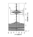
- FIG. 6 is a diagram showing the experimental results of Experiment 2.
- the output voltage in the range from time T 1 to time T 2 is surrounded by the frame R1 so that it can be easily compared with FIG.
- the range indicated by the frame R1 is the output voltage derived from the received wave 19 and the interference wave 20.
- the peak width of the output voltage of the frame R1 is +100 mV to -100 mV, which is clearly larger than that in the case of FIG.
- the S / N is improved in the case of FIG. 6 as compared with the case of FIG. Therefore, as in the case of FIG. 6, the S / N can be improved by simultaneously transmitting the transmission wave 17 and the transmission wave 18 from the sound wave element 12 and the sound wave element 13.
- Experiment 1 and Experiment 2 the experiment was performed on a scale of 1/10 of the room 2, but under the actual indoor conditions, the output voltage is small as a whole, so that the signal is amplified and the S / N is increased. Further improvement over Experiment 1 and Experiment 2.
- the detection unit 35 calculates the relative humidity based on the output voltage of the sound wave element 12 in a state where the following conditions (A) to (C) are satisfied.
- the S / N of the output voltage is improved, and it is possible to measure the humidity in the air with higher accuracy even in a wide space.
- the sound wave elements 12 and 13 emit ultrasonic waves
- the sound wave elements 12 and 13 may emit audible sound waves having a frequency of 20 kHz or less.
- the phenomenon is the same, only the frequency and wavelength are different with respect to the ultrasonic wave. Therefore, the same effect as in the case of ultrasonic waves is obtained.
- the output voltage of the sound wave element 12 is measured, but the same effect can be obtained by using the output voltage of the sound wave element 13.
- the number of sound wave elements may be any number N of 3 or more.
- the humidity is measured based on the output voltage from any one or more sound wave elements.
- the distance between the i-th ultrasonic element to the reflecting surface 4 and L i the distance up to the reflecting surface 4 (i + 1) -th ultrasonic element L Let i + 1 .
- the i-th sound wave element and the (i + 1) -th sound wave element are arranged so that the difference between the distance Li and the distance Li + 1 is an integral multiple of the wavelength ⁇ . It should be installed.
- the sound wave element 12 receives the interference wave 20, so that the sound wave element 12 can receive the overlapping ultrasonic waves, so that the S / N is improved. As a result, the humidity of the room 2 can be obtained with high accuracy.
- the sound wave element 12 and the sound wave element 13 are installed so that the difference between the first distance L1 and the second distance L2 is an integral multiple of the wavelength ⁇ .
- the ultrasonic waves emitted from the sound wave element 12 and the sound wave element 13 are intensified.
- the reception result of the sound wave element 12 is strengthened, and the S / N is improved.
- the detection unit 35 obtains the humidity using the data table stored in the storage unit 37. As a result, the calculation load of the detection unit 35 can be reduced.
- FIG. 7 is a side sectional view schematically showing the configuration of the air conditioner 1 according to the second embodiment.
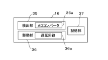
- FIG. 8 is a block diagram showing the configuration of the controller 16 of the humidity sensor 11 according to the second embodiment.
- the differences between the first embodiment and the second embodiment are the following two points.
- the humidity sensor 11 is composed of two sensor units 11A and 11B, but in the second embodiment, as shown in FIG. 7, the humidity sensor 11 is one sensor. It is composed of the unit 11C.
- the second is that the drive unit 36 of the controller 16 has a delay circuit 36a as shown in FIG.
- the sound wave element 12 and the sound wave element 13 are installed at a position where ultrasonic interference occurs, so that a condition for generating an interference wave 20 is obtained.
- the same condition is realized by shifting the application time of the pulse wave to the sound wave element 12 and the sound wave element 13 by the delay circuit 36a.
- the sound wave element 12 and the sound wave element 13 can be integrated and incorporated in one sensor unit 11C.
- the first distance L1 and the second distance L2 are substantially the same. Since other configurations and operations are the same as those in the first embodiment, the description thereof will be omitted here.
- the delay circuit 36a delays the time for the drive unit 36 to apply the pulse wave to the sound wave elements 12 and 13 by a preset delay time Td. That is, the delay circuit 36a delays the transmission timing of either the sound wave element 12 or the sound wave element 13 by the delay time Td with respect to the transmission timing of the other.
- the delay time Td is preset for each of the sound wave elements 12 and 13. As a result, for example, the sound wave element 13 transmits the transmitted wave 18 with a delay time Td behind the transmission time of the transmitted wave 17 of the sound wave element 12.
- the delay time Td is determined in the range of 0 ⁇ Td ⁇ 1/2 ⁇ T with respect to the period T of the ultrasonic waves transmitted from the sound wave element 12 and the sound wave element 13.
- the time point of application to the sound wave element 12 is 0 ms. Further, the timing of application to the sound wave element 13 is delayed by a preset delay time Td from 0 ms by using the delay circuit 36a. That is, the drive unit 36 applies the pulse wave to the sound wave element 12 when the elapsed time is 0 ms, and applies the pulse wave to the sound wave element 13 when the elapsed time is 0 ms + Td.
- the delay time Td is not set to one fixed value, but a plurality of delay times Td are prepared in advance.
- the first time is the delay time Td1
- the second time is the delay time Td2
- the third time is the delay time Td3. This will be specifically described.
- the detection unit 35 obtains the square-integrable value shown in FIG. 5 from the output voltage of the sound wave element 12 for each of the first to third times.
- the detection unit 35 determines that the interference wave 20 has occurred when the square-integrable integrated value is the largest among the square-integrable integrated values, and selects the square-integrable integrated value.
- the step size of the cycle T is set to 1/12 of the cycle T here, but it may be further subdivided.
- the sound wave element 12 and the sound wave element 13 are installed in the sensor unit 11C.
- the sound wave element 12 and the sound wave element 13 may be installed in separate sensor units 11A and 11B.
- the application time of the pulse wave by the drive unit 36 may be delayed by the delay time Td by using the delay circuit 36a.
- the detection unit 35 calculates the relative humidity based on the output voltage of the sound wave element 12 in a state where the following conditions (A) to (C) are satisfied. As a result, the S / N of the output voltage is improved, and it is possible to measure the humidity in the air with higher accuracy even in a wide space.
- the delay circuit 36a shifts the ultrasonic wave transmission timing of the sound wave element 12 and the ultrasonic wave transmission timing of the sound wave element 13 by the delay time Td.
- the delay time Td that maximizes the voltage output of the sound wave element 12 may be selected from the set of the plurality of delay times Td.
- C The sound wave element 12 receives the interference wave 20. Humidity is obtained based on the output voltage including the component derived from the interference wave 20 in the range from time T 1 to time T 2 surrounded by the frame R1 among the output voltage from the sound wave element 12.
- (A) is not an indispensable condition. That is, in the second embodiment, as shown in (B) above, the delay circuit 36a is used to shift the ultrasonic wave transmission time between the sound wave element 12 and the sound wave element 13 so that the ultrasonic waves strengthen each other. As a result, the sound wave element 12 receives the intensified ultrasonic waves and outputs the output voltage.
- the detection unit 35 calculates the square-integrable value from the output voltage and calculates the relative humidity. As a result, the S / N of the output voltage is improved, which has the effect of making it possible to measure the humidity in the air with higher accuracy.
- Embodiment 3 has basically the same configuration as the first embodiment, but the position of the reflecting surface 4 is different from that of the first embodiment. Therefore, in the following description, reference will be made to FIGS. 1 and 2.
- the reflective surface 4 is basically fixed to the floor surface 39 and the wall surface 38 of the room 2 .
- the layout of the room 2 it is necessary to relocate the reflective surface 4.
- the positions of the sound wave element 12 and the sound wave element 13 that satisfy the condition for generating the interference wave 20 shown in the first embodiment are displaced. Therefore, in many cases, the output voltage is likely to decrease.
- the third embodiment there is a distance D3 between the sound wave element 12 and the sound wave element 13 as in the above-described first and second embodiments. Therefore, since the sound wave element 12 and the sound wave element 13 have different inclinations with respect to the reflecting surface 4, a phase shift occurs. Therefore, it is desirable to set a plurality of delay times instead of one delay time. That is, as in the second embodiment, a plurality of delay times Td are prepared in advance instead of being set to one fixed value.
- the first time is the delay time Td1
- the second time is the delay time Td2
- the third time is the delay time Td3.
- the delay times Td1, Td2, and Td3 are set to the same values as in the second embodiment, for example.
- the detection unit 35 determines that the interference wave 20 has occurred when the square-integrable integrated value obtained from any of the output voltages of the 1st to 3rd times is the largest, and assumes that the delay time corresponds to the displacement of the position. , Correct the obtained relative humidity.
- the delay time is set in advance and the relative humidity is measured so that even if the position of the reflecting surface 4 changes, the humidity with a high S / N can always be measured. It produces the possible effects.
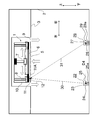
- FIG. 9 is a side sectional view schematically showing the configuration of the air conditioner 1 according to the fourth embodiment.
- the following two points are different from the above-described first embodiment.
- the first point is that in FIG. 9, only the sensor unit 11A is arranged out of the two sensor units 11A and 11B of FIG.
- the configuration of the sensor unit 11A is the same as that of the sensor unit 11A of the first embodiment. Therefore, the sound wave element 12 provided in the sensor unit 11A is a first sound wave element that transmits and receives sound waves.
- the second point is that the ultrasonic wave generating units 22 and 26 are installed instead of the reflecting surface 4 of FIG. Other configurations and operations are the same as those in the first embodiment.
- the ultrasonic wave generation unit 22 has a sound wave element 23, an electric wire 24, and a controller 25.
- the sound wave element 23 is connected to the controller 25 via the electric wire 24.
- the controller 25 drives the sound wave element 23.
- the sound wave element 23 is a second sound wave element that transmits sound waves. Therefore, the ultrasonic wave generation unit 22 has the same configuration as the sensor unit 11B shown in FIG.
- the ultrasonic wave generation unit 26 has a sound wave element 27, an electric wire 28, and a controller 29.
- the sound wave element 27 is connected to the controller 29 via an electric wire 28.
- the controller 29 drives the sound wave element 27.
- the sound wave element 27 is a second sound wave element that transmits sound waves. Therefore, the ultrasonic wave generation unit 26 has the same configuration as the sensor unit 11B shown in FIG.
- the ultrasonic wave generation units 22 and 26 are not fixed, but can be physically and automatically moved by a motor (not shown) or the like. The operation of the motor is controlled by the controller 16.
- the number of ultrasonic wave generation units is two, but one or three or more may be used.
- the number of sensor units 11A may be not one but a plurality.
- the sensor unit 11A and the ultrasonic wave generation unit 22 may be interchanged and installed.
- the ultrasonic waves of the sound wave elements 23 and 27 reach the sensor unit 11A as transmitted waves 30 and 31, respectively.
- the controllers 25 and 29 apply pulse waves to the sound wave elements 23 and 27, respectively, in the same manner as the drive unit 36 described in the second embodiment. As a result, the sound wave elements 23 and 27 generate ultrasonic waves.
- controller 29 has a delay circuit 29a.
- the configuration and operation of the delay circuit 29a are the same as those of the delay circuit 36a of the drive unit 36 described in the second embodiment.
- the sound wave element 23 By applying a pulse wave having a frequency of 40 kHz to the sound wave element 23 in the controller 25, the sound wave element 23 generates ultrasonic waves.
- the ultrasonic wave reaches the sensor unit 11A as a transmission wave 30.
- the application time to the sound wave element 27 is delayed by the delay time Td using the delay circuit 29a.
- the ultrasonic waves generated from the sound wave element 27 reach the humidity sensor 11 as a transmission wave 31.
- a plurality of delay times Td are prepared in advance instead of being set to one fixed value.
- the first time is the delay time Td1
- the second time is the delay time Td2
- the third time is the delay time Td3.
- the delay times Td1, Td2, and Td3 are set to the same values as in the second embodiment, for example.
- the detection unit 35 determines that the interference wave 20 has occurred at the delay time when the square-integrable integrated value is the largest among the square-integrable integrated values obtained based on the output voltage of the sound wave element 12 for the first to third times. ..
- the step size of the cycle T is set to 1/12 of the cycle T, but the point that it may be further subdivided is the same as that of the second embodiment.
- the effect of the fourth embodiment is the same as that of the second embodiment. That is, the transmission times of the transmitted waves 30 and 31 are shifted by using the delay circuit 29a so that the ultrasonic waves of the sound wave element 23 and the sound wave element 27 strengthen each other. As a result, the S / N of the output voltage is improved, which has the effect of enabling more accurate measurement of the humidity in the air.
- the ultrasonic waves emitted from the sound wave element 23 and the sound wave element 27 are emitted.
- the ultrasonic waves may be strengthened.
- the sound wave element 23 and the sound wave element 27 simultaneously transmit ultrasonic waves.
- the distance between the sound wave element 23 and the sensor unit 11A is the first distance L1
- the distance between the sound wave element 27 and the sensor unit 11A is the second distance L2
- the difference between the first distance L1 and the second distance L2 is.
- the sound wave element 23 and the sound wave element 27 are arranged so as to be an integral multiple of the wavelength ⁇ .
- the positions of the sound wave element 23 and the sound wave element 27 are gradually changed, and the sound wave element 23 and the sound wave element 27 are arranged at a position where the output power from the sound wave element 12 of the sensor unit 11A is maximized.
- the controller 29 has the delay circuit 29a.
- the controller 25 may have a delay circuit 25a.
- both the controllers 29 and 25 may have delay circuits 29a and 25a, respectively.
- the delay circuits 29a or 25a provided in the controllers 29 and 25 shift the transmission times of the transmitted waves 30 and 31 to strengthen the ultrasonic waves of the sound wave element 23 and the sound wave element 27.
- the S / N of the output voltage is improved, which has the effect of enabling more accurate measurement of the humidity in the air.
- FIG. 10 is a side sectional view schematically showing the configuration of the humidity sensor 11 according to the fifth embodiment.
- the humidity sensor 11 is composed of one sensor unit 11D.
- the sensor unit 11C shown in the second embodiment has two sound wave elements 12 and 13, but in the fifth embodiment, as shown in FIG. 10, the sensor unit 11D has seven sound wave elements. 40 is provided. Only this point is different from the second embodiment. Therefore, other configurations and operations are the same as in the second embodiment.
- the number of sound wave elements 40 is 7, but the number is not limited to that case.
- the number of sound wave elements 40 may be any number. At least one of the sound wave elements 40 is a first sound wave element that transmits and receives ultrasonic waves, and the other sound wave element 40 is a second sound wave element that transmits ultrasonic waves.
- the sound wave element 40 is arranged as an example on the straight line P. More specifically, the ultrasonic emission ports of the sound wave element 40 are arranged in a row on a straight line P.
- one of the sound wave elements 40 is called a sound wave element 41.
- the sound wave element 40 adjacent to the sound wave element 41 is referred to as a sound wave element 42 and 43, respectively.
- the sound wave element 42 is arranged on the right side of the sound wave element 41.
- the sound wave element 43 is arranged on the left side of the sound wave element 41.
- the linear distance between the sound wave element 41 and the reflecting surface 4 is defined as the distance L k
- the linear distance between the sound wave element 42 and the reflecting surface 4 is defined as the distance L k + 1 .
- n is an integer
- the ultrasonic waves emitted from the sound wave element 41 and the sound wave element 42 intensify each other when the following equation (3) holds with respect to the difference in distance (L k ⁇ L k + 1). .. That is, when the difference in distance (L k ⁇ L k + 1 ) becomes an integral multiple of the wavelength ⁇ , the ultrasonic waves emitted from the sound wave element 41 and the sound wave element 42 intensify each other.
- the present invention is not limited to that case. That is, the same applies to the sound wave elements 40 arranged at distant positions.
- the sound wave element 42 and the sound wave element 43 will be described as an example.
- the linear distance between the sound wave element 42 and the reflecting surface 4 is defined as the distance L k + 1
- the linear distance between the sound wave element 43 and the reflecting surface 4 is defined as the distance L k-1 .
- n is an integer
- the ultrasonic waves emitted from the sound wave element 42 and the sound wave element 43 are generated when the following equation (4) holds for the difference in distance (L k + 1- L k-1). Strengthen each other. That is, when the difference in distance (L k + 1- L k-1 ) becomes an integral multiple of the wavelength ⁇ , the ultrasonic waves emitted from the sound wave element 42 and the sound wave element 43 intensify each other.
- the difference in distance between any plurality of sound wave elements 40 and the reflecting surface 4 may be configured to be an integral multiple of the wavelength ⁇ .
- the effect of the fifth embodiment is the same as that of the first or second embodiment. Also in the fifth embodiment, ultrasonic waves are simultaneously transmitted from the sound wave element 41 and the sound wave element 42, or the transmission time of the ultrasonic waves is shifted by using a delay circuit so that the ultrasonic waves strengthen each other. Thereby, the ultrasonic wave is detected by the sound wave element 41, the square-integrable value of the voltage output of the sound wave element 41 is calculated by the detection unit 35, and the relative humidity is calculated. As a result, the S / N of the output voltage is improved, which has the effect of enabling more accurate measurement of the humidity in the air.
- the delay time Td may be set for each of the plurality of sound wave elements 40 so that the plurality of sound wave elements 40 are operated in time series. .. In that case, the detection unit 35 selects the maximum voltage output from the plurality of voltage outputs from the plurality of sound wave elements 40.
Landscapes
- Physics & Mathematics (AREA)
- Health & Medical Sciences (AREA)
- Life Sciences & Earth Sciences (AREA)
- Chemical & Material Sciences (AREA)
- Analytical Chemistry (AREA)
- Biochemistry (AREA)
- General Health & Medical Sciences (AREA)
- General Physics & Mathematics (AREA)
- Immunology (AREA)
- Pathology (AREA)
- Acoustics & Sound (AREA)
- Air Conditioning Control Device (AREA)
Priority Applications (2)
| Application Number | Priority Date | Filing Date | Title |
|---|---|---|---|
| JP2020531792A JP6746048B1 (ja) | 2020-03-03 | 2020-03-03 | 湿度センサ |
| PCT/JP2020/008814 WO2021176545A1 (ja) | 2020-03-03 | 2020-03-03 | 湿度センサ |
Applications Claiming Priority (1)
| Application Number | Priority Date | Filing Date | Title |
|---|---|---|---|
| PCT/JP2020/008814 WO2021176545A1 (ja) | 2020-03-03 | 2020-03-03 | 湿度センサ |
Publications (1)
| Publication Number | Publication Date |
|---|---|
| WO2021176545A1 true WO2021176545A1 (ja) | 2021-09-10 |
Family
ID=72146154
Family Applications (1)
| Application Number | Title | Priority Date | Filing Date |
|---|---|---|---|
| PCT/JP2020/008814 Ceased WO2021176545A1 (ja) | 2020-03-03 | 2020-03-03 | 湿度センサ |
Country Status (2)
| Country | Link |
|---|---|
| JP (1) | JP6746048B1 (cg-RX-API-DMAC7.html) |
| WO (1) | WO2021176545A1 (cg-RX-API-DMAC7.html) |
Cited By (1)
| Publication number | Priority date | Publication date | Assignee | Title |
|---|---|---|---|---|
| JPWO2023286207A1 (cg-RX-API-DMAC7.html) * | 2021-07-14 | 2023-01-19 |
Citations (11)
| Publication number | Priority date | Publication date | Assignee | Title |
|---|---|---|---|---|
| JPS56650A (en) * | 1979-04-20 | 1981-01-07 | Framatome Sa | Method and device for inspecting fuel rod for nuclear reactor |
| JPS59212761A (ja) * | 1983-05-19 | 1984-12-01 | Fuigaro Giken Kk | 気体成分検出装置 |
| JPS59212760A (ja) * | 1983-05-19 | 1984-12-01 | Fuigaro Giken Kk | 気体成分検出装置 |
| JPH0367195A (ja) * | 1989-08-04 | 1991-03-22 | Tokai Univ | 波動伝播を利用した大気の温度及び湿度測定方法及び装置 |
| JP2007128758A (ja) * | 2005-11-04 | 2007-05-24 | Toyota Motor Corp | 燃料電池システム及び燃料電池内のガス成分状態検出方法 |
| WO2009054359A1 (ja) * | 2007-10-26 | 2009-04-30 | Panasonic Electric Works Co., Ltd. | 火災警報システム |
| JP2009257978A (ja) * | 2008-04-18 | 2009-11-05 | Denso Corp | 超音波センサ |
| JP2010018432A (ja) * | 2008-06-13 | 2010-01-28 | Canon Inc | 記録媒体の坪量検知センサ、及び画像形成装置 |
| JP2014095600A (ja) * | 2012-11-08 | 2014-05-22 | Panasonic Corp | 温度測定のための伝搬時間計測システム、及び温度測定のための伝搬時間計測方法 |
| JP2014130113A (ja) * | 2012-12-28 | 2014-07-10 | Panasonic Corp | 超音波送信装置、超音波受信装置、超音波送信方法、超音波受信方法、温度測定のための伝搬時間計測システム、及び温度測定のための伝搬時間計測方法 |
| WO2017149883A1 (ja) * | 2016-03-03 | 2017-09-08 | 三菱電機株式会社 | 空気調和機 |
-
2020
- 2020-03-03 WO PCT/JP2020/008814 patent/WO2021176545A1/ja not_active Ceased
- 2020-03-03 JP JP2020531792A patent/JP6746048B1/ja active Active
Patent Citations (11)
| Publication number | Priority date | Publication date | Assignee | Title |
|---|---|---|---|---|
| JPS56650A (en) * | 1979-04-20 | 1981-01-07 | Framatome Sa | Method and device for inspecting fuel rod for nuclear reactor |
| JPS59212761A (ja) * | 1983-05-19 | 1984-12-01 | Fuigaro Giken Kk | 気体成分検出装置 |
| JPS59212760A (ja) * | 1983-05-19 | 1984-12-01 | Fuigaro Giken Kk | 気体成分検出装置 |
| JPH0367195A (ja) * | 1989-08-04 | 1991-03-22 | Tokai Univ | 波動伝播を利用した大気の温度及び湿度測定方法及び装置 |
| JP2007128758A (ja) * | 2005-11-04 | 2007-05-24 | Toyota Motor Corp | 燃料電池システム及び燃料電池内のガス成分状態検出方法 |
| WO2009054359A1 (ja) * | 2007-10-26 | 2009-04-30 | Panasonic Electric Works Co., Ltd. | 火災警報システム |
| JP2009257978A (ja) * | 2008-04-18 | 2009-11-05 | Denso Corp | 超音波センサ |
| JP2010018432A (ja) * | 2008-06-13 | 2010-01-28 | Canon Inc | 記録媒体の坪量検知センサ、及び画像形成装置 |
| JP2014095600A (ja) * | 2012-11-08 | 2014-05-22 | Panasonic Corp | 温度測定のための伝搬時間計測システム、及び温度測定のための伝搬時間計測方法 |
| JP2014130113A (ja) * | 2012-12-28 | 2014-07-10 | Panasonic Corp | 超音波送信装置、超音波受信装置、超音波送信方法、超音波受信方法、温度測定のための伝搬時間計測システム、及び温度測定のための伝搬時間計測方法 |
| WO2017149883A1 (ja) * | 2016-03-03 | 2017-09-08 | 三菱電機株式会社 | 空気調和機 |
Non-Patent Citations (2)
| Title |
|---|
| KATAOKA, RYUJI: "Humidity measurement based on sound wave propagation characteristics", GRADUATION THESIS, 2005, Retrieved from the Internet <URL:http://ochiro.bpe.es.osaka-u.ac.jp/thesis/bachelor/2005/kataoka.pdf> * |
| TAKAHIRO MOTEGI: "Research on temperature and humidity measurement methods based on the sound velocity and attenuation of ultrasonic waves", DOCTORAL THESIS, 25 March 2014 (2014-03-25), pages i - 104, XP055856260, Retrieved from the Internet <URL:http://hdl.handle.net/2241/00123491> [retrieved on 20211029] * |
Cited By (1)
| Publication number | Priority date | Publication date | Assignee | Title |
|---|---|---|---|---|
| JPWO2023286207A1 (cg-RX-API-DMAC7.html) * | 2021-07-14 | 2023-01-19 |
Also Published As
| Publication number | Publication date |
|---|---|
| JP6746048B1 (ja) | 2020-08-26 |
| JPWO2021176545A1 (cg-RX-API-DMAC7.html) | 2021-09-10 |
Similar Documents
| Publication | Publication Date | Title |
|---|---|---|
| CN110383014B (zh) | 用于测量管道中流体的流速的设备和方法 | |
| US8519854B2 (en) | Fire alarm system | |
| RU2546855C1 (ru) | Определение времени задержки для ультразвуковых расходомеров | |
| JP5679758B2 (ja) | 厚さ測定装置およびその測定方法 | |
| CN114787590A (zh) | 用于测量经过通道的气体的流量的系统和方法 | |
| US9752907B2 (en) | Phase controlled variable angle ultrasonic flow meter | |
| KR20020086656A (ko) | 초음파에 의해 기체의 농도 및 유량을 측정하는 장치 및방법 | |
| CN203848888U (zh) | 发射角度可调超声波流量计探头 | |
| JP6746048B1 (ja) | 湿度センサ | |
| JP2008224674A (ja) | 導管内のフロート位置の光学検知を使用した可変面積型流量計 | |
| CN111141344A (zh) | 一种超声水表换能器及其超声水表 | |
| RU2330247C2 (ru) | Способ калибрования ультразвукового расходомера и настроечный датчик (варианты) | |
| US11573020B2 (en) | Air-conditioning apparatus including detector to detect contaminant adhered to drain pan | |
| CN121855640A (zh) | 基于静态声速及电路传输延时标定的计量方法及燃气表 | |
| CN1293370C (zh) | 流量计 | |
| JP6843309B1 (ja) | 湿度センサおよび空気調和機 | |
| CN106679593B (zh) | 一种基于到达时间的恒温环境的角度校准装置及校准方法 | |
| CN1479917A (zh) | 超声转换器及超声流量计 | |
| JPH0894594A (ja) | 超音波湿度センサ及び超音波温湿度センサ | |
| JP2003156376A (ja) | ガスwi計測装置およびガス燃焼流量計測装置ならびにそれらに用いられるガス密度計測器 | |
| JP7317204B2 (ja) | 空気調和機および空気調和機の製造方法 | |
| Zeng et al. | A method of temperature compensation for the ultrasound resonance wind speed and direction sensor in resonance-state | |
| US1712516A (en) | Electrical measuring device | |
| US1712515A (en) | Acoustimeter | |
| JP7634194B2 (ja) | 振動伝搬部材、およびこれを用いた送受波器、流速計、流量計 |
Legal Events
| Date | Code | Title | Description |
|---|---|---|---|
| ENP | Entry into the national phase |
Ref document number: 2020531792 Country of ref document: JP Kind code of ref document: A |
|
| 121 | Ep: the epo has been informed by wipo that ep was designated in this application |
Ref document number: 20923449 Country of ref document: EP Kind code of ref document: A1 |
|
| NENP | Non-entry into the national phase |
Ref country code: DE |
|
| 122 | Ep: pct application non-entry in european phase |
Ref document number: 20923449 Country of ref document: EP Kind code of ref document: A1 |