WO2021172403A1 - 車載用アンテナ装置 - Google Patents
車載用アンテナ装置 Download PDFInfo
- Publication number
- WO2021172403A1 WO2021172403A1 PCT/JP2021/007016 JP2021007016W WO2021172403A1 WO 2021172403 A1 WO2021172403 A1 WO 2021172403A1 JP 2021007016 W JP2021007016 W JP 2021007016W WO 2021172403 A1 WO2021172403 A1 WO 2021172403A1
- Authority
- WO
- WIPO (PCT)
- Prior art keywords
- antenna
- satellite
- vehicle
- base
- satellite antenna
- Prior art date
- Legal status (The legal status is an assumption and is not a legal conclusion. Google has not performed a legal analysis and makes no representation as to the accuracy of the status listed.)
- Ceased
Links
Images


Classifications
-
- H—ELECTRICITY
- H01—ELECTRIC ELEMENTS
- H01Q—ANTENNAS, i.e. RADIO AERIALS
- H01Q1/00—Details of, or arrangements associated with, antennas
- H01Q1/27—Adaptation for use in or on movable bodies
- H01Q1/32—Adaptation for use in or on road or rail vehicles
- H01Q1/325—Adaptation for use in or on road or rail vehicles characterised by the location of the antenna on the vehicle
- H01Q1/3275—Adaptation for use in or on road or rail vehicles characterised by the location of the antenna on the vehicle mounted on a horizontal surface of the vehicle, e.g. on roof, hood, trunk
-
- B—PERFORMING OPERATIONS; TRANSPORTING
- B60—VEHICLES IN GENERAL
- B60R—VEHICLES, VEHICLE FITTINGS, OR VEHICLE PARTS, NOT OTHERWISE PROVIDED FOR
- B60R11/00—Arrangements for holding or mounting articles, not otherwise provided for
- B60R11/02—Arrangements for holding or mounting articles, not otherwise provided for for radio sets, television sets, telephones, or the like; Arrangement of controls thereof
-
- H—ELECTRICITY
- H01—ELECTRIC ELEMENTS
- H01Q—ANTENNAS, i.e. RADIO AERIALS
- H01Q1/00—Details of, or arrangements associated with, antennas
- H01Q1/12—Supports; Mounting means
- H01Q1/1207—Supports; Mounting means for fastening a rigid aerial element
- H01Q1/1214—Supports; Mounting means for fastening a rigid aerial element through a wall
-
- H—ELECTRICITY
- H01—ELECTRIC ELEMENTS
- H01Q—ANTENNAS, i.e. RADIO AERIALS
- H01Q1/00—Details of, or arrangements associated with, antennas
- H01Q1/42—Housings not intimately mechanically associated with radiating elements, e.g. radome
-
- H—ELECTRICITY
- H01—ELECTRIC ELEMENTS
- H01Q—ANTENNAS, i.e. RADIO AERIALS
- H01Q21/00—Antenna arrays or systems
- H01Q21/30—Combinations of separate antenna units operating in different wavebands and connected to a common feeder system
-
- H—ELECTRICITY
- H01—ELECTRIC ELEMENTS
- H01Q—ANTENNAS, i.e. RADIO AERIALS
- H01Q9/00—Electrically-short antennas having dimensions not more than twice the operating wavelength and consisting of conductive active radiating elements
- H01Q9/04—Resonant antennas
- H01Q9/0407—Substantially flat resonant element parallel to ground plane, e.g. patch antenna
Definitions
- An embodiment of the present invention relates to an in-vehicle antenna device.
- in-vehicle antenna devices that can be attached to the roof of automobiles have been developed.
- a low-profile antenna device in which an antenna case is formed in a shark fin shape is disclosed.
- a patch antenna is mounted on the front side of the antenna base.
- the patch antenna receives, for example, radio waves in the GPS (Global Positioning System) wave band or radio waves in the SDARS (Satellite Digital Audio Radio Service) wave band.
- One example of the purpose of the embodiment is to improve the characteristics of the antenna mounted on the roof of an automobile.
- One aspect of this embodiment is With an antenna base that has a longitudinal direction, The first antenna portion provided on the antenna base and With The first antenna portion is an in-vehicle antenna device that is arranged so as to deviate from the virtual surface parallel to the longitudinal direction in the direction of intersection.
- Another aspect of the present invention is Antenna base and The first antenna portion provided on the antenna base and With The first antenna portion is an in-vehicle antenna device in which the center thereof is arranged so as to be displaced in the left-right direction with respect to the center line along the front-rear direction of the antenna base in the upward view of the antenna base.
- the characteristics of the antenna mounted on the roof of the automobile can be improved.
- ordinal numbers such as “first”, “second”, and “third” are added only for distinguishing configurations having similar names unless otherwise specified. , Does not mean a particular feature of the composition (eg, order or importance).
- FIG. 1 is a perspective view of the vehicle-mounted antenna device 10 according to the embodiment.
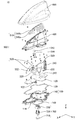
- FIG. 2 is an exploded perspective view showing an example of the vehicle-mounted antenna device 10 according to the embodiment.
- FIG. 3 is a left side view showing an example of a state in which the left side portion of the inner case 400 and the left side portion of the antenna case 600 are removed from the in-vehicle antenna device 10 according to the embodiment.
- FIG. 4 is a perspective view showing an example of a state in which the left side portion of the inner case 400, the capacitive loading element 510, and the left side portion of the antenna case 600 are removed from the in-vehicle antenna device 10 according to the embodiment. ..
- the first direction X, the second direction Y, and the third direction Z indicate the front-rear direction, the left-right direction, and the up-down direction of the in-vehicle antenna device 10, respectively.
- the positive direction of the first direction X is the direction of the arrow indicating the first direction X, and indicates the front direction of the vehicle-mounted antenna device 10.
- the negative direction of the first direction X is the opposite direction of the arrow indicating the first direction X, and indicates the rear direction of the vehicle-mounted antenna device 10.
- the positive direction of the second direction Y is the direction of the arrow indicating the second direction Y, and indicates the left direction of the vehicle-mounted antenna device 10.
- the negative direction of the second direction Y is the opposite direction of the arrow indicating the second direction Y, and indicates the right direction of the vehicle-mounted antenna device 10.
- the white circle with a black dot indicating the second direction Y is a direction in which the positive direction of the second direction Y is from the back to the front of the paper surface of FIG. 3, and the negative direction of the second direction Y is the direction of FIG. It indicates that the direction is from the front to the back of the page.
- the positive direction of the third direction Z is the direction of the arrow indicating the third direction Z, and indicates the upward direction of the vehicle-mounted antenna device 10.
- the negative direction of the third direction Z is the opposite direction of the arrow indicating the third direction Z, and indicates the downward direction of the vehicle-mounted antenna device 10.
- the "front”, “rear”, “left”, “right”, “upper” and “lower” referred to here are determined by the automobile on which the in-vehicle antenna device 10 is mounted. That is, the forward direction is the forward direction of the automobile, and the backward direction is the backward direction of the automobile.
- the left direction is the left direction when viewed from the rear side to the front side of the automobile, and the right direction is the right direction when viewed from the rear side to the front side of the automobile.
- the upward direction is the upward direction of the automobile
- the downward direction is the downward direction of the automobile.
- the first direction X, the second direction Y, and the third direction Z are used for the vehicle-mounted antenna device 10, or the vehicle-mounted antenna device 10 such as the antenna base 100, the inner case 400, and the antenna case 600, respectively. It is referred to as the front-rear direction, the left-right direction, and the up-down direction of the members constituting the above. Further, if necessary, the positive direction of the first direction X, the negative direction of the first direction X, the positive direction of the second direction Y, the negative direction of the second direction Y, the positive direction of the third direction Z, and the third direction.
- the negative directions of Z are the front direction, the rear direction, the left direction, and the right direction of the vehicle-mounted antenna device 10, or the members constituting the vehicle-mounted antenna device 10 such as the antenna base 100, the inner case 400, and the antenna case 600, respectively. Referred as upward and downward.
- the in-vehicle antenna device 10 includes an antenna base 100, a first substrate 120, a pad 130, a first satellite antenna 210, a second satellite antenna 220, a first antenna 310, and a second antenna 320.
- the inner case 400, the third antenna 500, the antenna case 600, and the antenna mounting portion 700 are provided.
- the first satellite antenna 210 and the second satellite antenna 220 are examples of the first antenna portion
- the first antenna 310, the second antenna 320, the inner case 400, and the third antenna 500 are examples of the second antenna portion. be.
- the antenna case 600 is a member that covers the members constituting the in-vehicle antenna device 10, and is a resin molded product made of a synthetic resin having non-translucency and radio wave transmission.
- the antenna case 600 has, for example, a shark fin shape in which the front side of the first direction X is inclined so as to be lower than the rear side of the first direction X, and both side surfaces are curved inward.
- the lower surface of the antenna case 600 is open and covers the inner case 400 and the like from above in the third direction Z.
- the first satellite antenna 210, the second satellite antenna 220, the first antenna 310, the second antenna 320, the inner case 400, and the third antenna 500 are placed. It is stored.
- the inner case 400 is a resin molded product made of a synthetic resin or the like having radio wave transmission, and the lower surface is open to cover the antenna base 100 and the like from above in the third direction Z.
- the first satellite antenna 210, the second satellite antenna 220, the first antenna 310, and the second antenna 320 are housed in the space formed by the inner case 400 and the antenna base 100.
- the antenna base 100 has a metal base 110.
- the metal base 110 and the first substrate 120 have a longitudinal direction in the first direction X. Further, the metal base 110 and the first substrate 120 have a lateral direction in the second direction Y. That is, the length of the antenna base 100 in the first direction X is longer than the length of the antenna base 100 in the second direction Y. Further, the metal base 110 and the first substrate 120 have a thickness in the third direction Z.
- the longitudinal direction of the antenna base 100 can be referred to as the front-rear direction, and the lateral direction thereof can be referred to as the left-right direction.
- a connector 122 is provided on the lower surface of the first substrate 120.
- the first substrate 120 is mounted on the upper surface of the metal base 110.
- the metal base 110 is formed with a hole 114 through which the connector 122 can pass.
- the connector 122 penetrates the hole 114 of the metal base 110 and projects downward from the lower surface of the metal base 110.
- the pad 130 is arranged on the metal base 110 and is located on the outer periphery of the first substrate 120. The pad 130 fills the space between the metal base 110 and the inner case 400 to make it waterproof.
- the antenna base 100 is mounted on the roof of the automobile via the seal member 140, and is fixed to the roof of the automobile by the antenna mounting portion 700.
- the sealing member 140 is an annular elastic member such as an elastomer, urethane, or rubber.
- the seal member 140 is sandwiched between the lower surface of the antenna base 100 and the vehicle body (for example, the vehicle roof) to which the in-vehicle antenna device 10 is attached, and watertightly seals between the two.
- the lower surface of the metal base 110 is provided with a fixing portion 112 that projects downward (the negative direction of the third direction Z).
- the fixing portion 112 is conductive, and is, for example, a conductive block such as a metal block.
- the antenna base 100 may be configured to include an insulating member in part as long as the fixed portion 112 is conductive, or the entire antenna base 100 may be configured to be a conductive member.
- a screw hole is formed on the tip surface of the fixing portion 112 (the surface on the negative direction side of the third direction Z).
- An example of the method of fixing the antenna base 100 by the antenna mounting portion 700 is as follows. First, the washer 720 and the holder 730 of the antenna mounting portion 700 are mounted on the fixing portion 112 of the antenna base 100. Next, the bolt 710 of the antenna mounting portion 700 is inserted into the screw hole formed on the lower surface of the fixing portion 112 of the antenna base 100. As a result, the bolt 710, the washer 720 and the holder 730 are temporarily fixed to the fixing portion 112 of the antenna base 100. Next, the antenna base 100 is mounted on the upper surface of the roof via the seal member 140.
- the fixed portion 112 of the antenna base 100 and the antenna mounting portion 700 temporarily fixed to the fixed portion 112 are passed through the mounting holes formed in the roof, and the in-vehicle antenna is mounted on the roof by the holder 730.
- the device 10 is temporarily fixed.
- the claw portion of the washer 720 is brought into contact with the lower surface of the roof, and the antenna base 100 is fixed to the roof.
- a first satellite antenna 210, a second satellite antenna 220, a first antenna 310, a second antenna 320, and a second board 522 are provided on the upper surface of the first substrate 120.
- the first satellite antenna 210, the second satellite antenna 220, the first antenna 310, the second antenna 320, and the second substrate 522 are covered with an inner case 400.
- a capacitive loading element 510 is attached to the inner case 400.
- the inner case 400 and the third antenna 500 are covered by the antenna case 600.
- the first antenna 310 is, for example, a V2X (Vehicle-to-Everything) antenna.
- the first antenna 310 may be a shared antenna of Wi-Fi (registered trademark) or Bluetooth (registered trademark) and V2X, or may be a shared antenna of V2X with another antenna operating in another frequency band.
- the in-vehicle antenna device 10 is further miniaturized.
- the first antenna 310 may be a shared antenna of Wi-Fi (registered trademark) or Bluetooth (registered trademark) and V2X, or may be a shared antenna of TEL and V2X. When the first antenna 310 is used as a shared antenna, further miniaturization becomes possible.
- the first antenna 310 is located on the rear side of the antenna base 100. That is, the first antenna 310 is located in the first direction X on the negative direction side of the first direction X from the center of the antenna base 100.
- the first antenna 310 is covered with an inner case 400. Therefore, the height of the first antenna 310 in the third direction Z is limited by the height of the inner case 400 in the third direction Z. Further, the height of the inner case 400 on the rear side of the antenna base 100 is higher than the height of the inner case 400 on the front side of the antenna base 100. Therefore, the height of the first antenna 310 can be increased as compared with the case where the first antenna 310 is located on the front side of the antenna base 100. As a result, the degree of freedom for adjusting the first antenna 310 to the desired antenna performance is increased.
- the second antenna 320 is, for example, a TEL (Telephone) antenna.
- the second antenna 320 is located in the first direction X on the negative direction side of the first direction X from the center of the antenna base 100 and on the positive direction side of the first direction X from the position of the first antenna 310. Further, the second antenna 320 is arranged between the first satellite antenna 210 and the second satellite antenna 220 in the second direction Y.
- the second antenna 320 is covered with an inner case 400. Therefore, the height of the second antenna 320 in the third direction Z is limited by the height of the inner case 400 in the third direction Z. Further, the height of the inner case 400 on the rear side of the antenna base 100 is higher than the height of the inner case 400 on the front side of the antenna base 100. Therefore, the height of the second antenna 320 can be increased as compared with the case where the second antenna 320 is located on the front side of the antenna base 100. As a result, the degree of freedom for adjusting the second antenna 320 to the desired antenna performance is increased.
- the first antenna 310 and the second antenna 320 are located on the same straight line extending along the first direction X. However, the first antenna 310 and the second antenna 320 may be arranged so as to be offset from each other in the second direction Y.
- the width of the portion of the inner case 400 that covers the first antenna 310 in the second direction Y is close to the width of the first antenna 310 in the second direction Y.
- the width of the first antenna 310 in the second direction Y is more than 100% and 110% or less. If there is a gap of a certain size between the inner surface of the inner case 400 and the first antenna 310, the radio waves of the first antenna 310 may be reflected by a material such as resin constituting the inner case 400. In the present embodiment, the reflection of radio waves of the first antenna 310 can be suppressed by making the size of the gap between the inner surface of the inner case 400 and the first antenna 310 smaller than a certain size. Therefore, the directivity of the first antenna 310 can be made uniform as compared with the case where there is a gap of a certain size between the inner surface of the inner case 400 and the first antenna 310.
- the third antenna 500 is, for example, an AM / FM (Amplitude Modulation / Frequency Modulation) radio antenna.
- the third antenna 500 has a capacitive loading element 510 and a helical element 520.
- the capacitive loading element 510 and the helical element 520 enable the third antenna 500 to receive AM / FM broadcasts.
- the capacitive loading element 510 includes a first element 510a and a second element 510b.
- the first element 510a is attached to the left side surface of the inner case 400.
- the second element 510b is attached to the right side surface of the inner case 400.
- the first element 510a and the second element 510b are electrically connected via the connecting member 512.
- the helical element 520 is arranged on the second substrate 522.
- the capacitive loading element 510 and the helical element 520 are electrically connected. Specifically, the connecting member 512 is connected to the connecting member 514, and the connecting member 514 is connected to the
- Each of the first element 510a and the second element 510b of the capacitive loading element 510 has a meander shape.
- each element of the capacitive loading element 510 has a vertical meander shape having a folded structure in the vertical direction.
- electrical interference includes radio wave interference and impedance interference.
- a second antenna 320 is arranged below the capacitive loading element 510.
- the first satellite antenna 210 and the second satellite antenna 220 are arranged outside the region where the capacitive loading element 510 is projected onto the antenna base 100. In other words, the first satellite antenna 210 and the second satellite antenna 220 do not overlap in the third direction Z. Specifically, the first satellite antenna 210 is arranged so as to be offset from the rear portion of the first element 510a, specifically, the first element 510a, to the positive side of the second direction Y when viewed from the third direction Z. ing. Further, the second satellite antenna 220 is arranged so as to be offset from the rear portion of the second element 510b, specifically, the second element 510b, to the negative direction side of the second direction Y when viewed from the third direction Z. ..
- the capacitive loading element 510 and the first satellite antenna 210 are compared with the case where the first satellite antenna 210 and the second satellite antenna 220 are arranged in the region where the capacitive loading element 510 is projected onto the antenna base 100.
- electrical interference with the second satellite antenna 220 can be reduced.
- the capacitive loading element 510 is provided on the front side portion of the inner case 400.
- the height of the front portion of the inner case 400 in the third direction Z is lower than the height of the rear portion of the inner case 400 in the third direction Z. Therefore, the length of the capacitive loading element 510 in the third direction Z is limited by the height of the inner case 400 in the third direction Z. If the distance between the capacitive loading element 510 and the metal base 110 cannot be increased, the performance of the third antenna 500 may deteriorate. In the present embodiment, the performance of the third antenna 500 is not significantly deteriorated by widening the width of the lower portion of the capacitive loading element 510 instead of being restricted by the height in the third direction Z.
- the distance between the lower portion of the first element 510a and the lower portion of the second element 510b is the upper portion of the first element 510a and the upper portion of the second element 510b. It is wider than the interval of.
- the first satellite antenna 210 is a GNSS (Global Navigation Satellite System) antenna, specifically a GPS antenna. However, the first satellite antenna 210 may be a satellite antenna different from the GNSS antenna.
- the first satellite antenna 210 is a patch antenna. Specifically, the first satellite antenna 210 has a thickness in the third direction Z. Further, when viewed from the third direction Z, the first satellite antenna 210 is a quadrangle, specifically, a substantially rectangular shape or a substantially square shape.
- the substantially rectangular shape means not only a strict rectangle but also a shape similar to a strict rectangle such as a rectangle with rounded corners and a rectangle with cut corners. The same applies to a substantially square.
- the substantially rectangular or substantially square portion of the first satellite antenna 210 has a pair of sides extending in the first direction X and another pair of sides extending in the second direction Y.
- the pair of sides of the substantially rectangular or substantially square of the first satellite antenna 210 and the other pair of sides have a constant angle, for example, 45 degrees with respect to the first direction X and the second direction Y, respectively. It may be tilted.
- the fixed angle is determined according to various factors. Since the first satellite antenna 210 is affected by the position of the third antenna 500, the factor may be, for example, the relationship between the position of the first satellite antenna 210 and the position of the third antenna 500.
- the second satellite antenna 220 is an SXM (SiriusXM) antenna. However, the second satellite antenna 220 may be a satellite antenna different from the SXM antenna.
- the second satellite antenna 220 is a patch antenna. Specifically, the second satellite antenna 220 has a thickness in the third direction Z. Further, when viewed from the third direction Z, the second satellite antenna 220 is a quadrangle, specifically, a substantially rectangular shape or a substantially square shape.
- the substantially rectangular shape means not only a strict rectangle but also a shape similar to a strict rectangle such as a rectangle with rounded corners and a rectangle with cut corners. The same applies to a substantially square.
- the substantially rectangular or substantially square portion of the second satellite antenna 220 has a pair of sides extending in the first direction X and another pair of sides extending in the second direction Y.
- the pair of sides of the substantially rectangular or substantially square portion of the second satellite antenna 220 and the other pair of sides have a constant angle, for example, 45 degrees with respect to the first direction X and the second direction Y, respectively. It may be tilted.
- the fixed angle is determined according to various factors. Since the second satellite antenna 220 is affected by the position of the third antenna 500, the factor may be, for example, the relationship between the position of the second satellite antenna 220 and the position of the third antenna 500.
- the non-feeding element 222 is arranged in the region of the inner case 400 facing the second satellite antenna 220.
- the non-feeding element 222 makes it possible to improve the antenna performance of the second satellite antenna 220.
- the non-feeding element 222 may be arranged in a region outside the inner case 400 and facing the second satellite antenna 220.
- the size of the first satellite antenna 210 and the size of the second satellite antenna 220 are substantially the same. However, the size of the first satellite antenna 210 and the size of the second satellite antenna 220 may be different from each other.
- the in-vehicle antenna device 10 configured in this way operates as a multi-media compound antenna.
- an in-vehicle antenna device it may be desired to accommodate many antennas, but the height and width are limited because of the shark fin shape. Therefore, in order to accommodate many antennas, for example, it is conceivable to arrange the antennas in the front-rear direction. However, when a plurality of antennas are arranged in the front-rear direction, the length in the front-rear direction becomes long.
- the first satellite antenna 210 and the second satellite antenna 220 are arranged so as to be offset from each other in the second direction Y.
- the first satellite antenna 210 and the second satellite antenna 220 are symmetrical with respect to the virtual surface P1 (hereinafter referred to as "virtual surface") passing through the center line C of the antenna base 100 along the first direction X. It is located in.
- the center line C of the antenna base 100 includes not only the exact center of the antenna base 100 but also a substantially center. This approximately center indicates that it does not necessarily have to be a strict center.
- the first satellite antenna 210 is arranged so as to be offset in the positive direction of the second direction Y with respect to the virtual surface when viewed from the third direction Z, that is, when the antenna base 100 is viewed upward.
- the 220 is arranged so as to be offset in the negative direction of the second direction Y with respect to the virtual surface when viewed from the third direction Z, that is, when the antenna base 100 is viewed upward.
- the first satellite antenna 210 and the second satellite antenna 220 may be arranged asymmetrically with respect to the virtual surface. Further, one of the first satellite antenna 210 and the second satellite antenna 220 may be located on the virtual surface.
- first satellite antenna 210 and the second satellite antenna 220 may be arranged so that their centers are displaced in the second direction Y with respect to the virtual surface.
- the virtual surface is a surface parallel to the longitudinal direction of the antenna base 100.
- parallel to the longitudinal direction of the antenna base 100 includes not only strict parallelism but also substantially parallelism. This substantially parallel indicates that it does not necessarily have to be exactly parallel.
- the virtual surface passing through the center of the antenna base 100 along the first direction X passes through the fixed portion 112, the first antenna 310, and the second antenna 320. Therefore, in the present embodiment, the first satellite antenna 210 and the second satellite antenna 220 with respect to the virtual surface passing through the fixed portion 112, the first antenna 310, or the second antenna 320 along the first direction X. It can also be said that they are arranged so as to be offset in the second direction Y. In this case, the first satellite antenna 210 and the second satellite antenna 220 may be arranged so as to be offset in the second direction Y with respect to the virtual surface passing through the center of the fixed portion 112 along the first direction X. can.
- first satellite antenna 210 is arranged so as to be displaced in the positive direction of the second direction Y with respect to the fixed portion 112 of the antenna base 100.
- second satellite antenna 220 is arranged so as to be displaced in the negative direction of the second direction Y with respect to the fixed portion 112 of the antenna base 100.
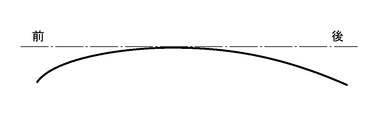
- FIG. 5 is a diagram schematically showing one cross section along the front-rear direction of the roof of the vehicle.
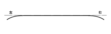
- FIG. 6 is a diagram schematically showing one cross section along the left-right direction of the roof of the vehicle.
- the solid line indicates the roof of the automobile, and the alternate long and short dash line indicates the direction parallel to the front-rear direction of the automobile.
- the solid line indicates the roof of the automobile, and the alternate long and short dash line indicates the direction parallel to the left-right direction of the automobile.
- the roof of an automobile has curvatures in the front-rear direction of the automobile and in the left-right direction of the automobile.
- the radius of curvature of the roof of the automobile in the front-rear direction is generally smaller than the radius of curvature of the roof of the automobile in the left-right direction. That is, in the present embodiment, the radius of curvature of the roof of the automobile on which the in-vehicle antenna device 10 is mounted in the first direction X may be smaller than the radius of curvature of the roof in the second direction Y.
- the antenna base 100 is closest to the roof in the third direction Z at the fixed portion 112.
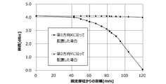
- FIG. 7 is a diagram showing an example of the amount of change in the zenith gain when the height from the roof to the satellite antenna mounting surface fluctuates.
- the X-axis shows the distance from the fixed portion 112 to the satellite antenna
- the Y-axis shows the zenith gain of the satellite antenna.
- FIG. 7 shows the change in the zenith gain of the SXM wave band when the satellite antenna is moved in parallel with the first direction X or the second direction Y.
- the case where the radius of the first direction X is 900 mm and the radius of the second direction Y is 10000 mm is taken as an example.
- the radius of curvature in the first direction X is smaller than the radius of curvature in the second direction Y.
- the gain in the zenith direction decreases as the distance between the satellite antenna and the fixed portion 112 increases.
- the satellite antenna is translated and arranged in the second direction Y, the gain in the zenith direction hardly changes even if the distance between the satellite antenna and the fixed portion 112 becomes long. In other words, the higher the height from the roof to the satellite antenna mounting surface, the lower the antenna performance of the satellite antenna at a high elevation angle.
- the radius of curvature of the automobile roof in the front-rear direction is generally smaller than the radius of curvature of the automobile roof in the left-right direction. That is, even if the distance between the satellite antenna and the fixed portion 112 is the same, when they are separated along the front-rear direction of the roof of the automobile, the satellite antenna is attached from the roof as compared with the case where they are separated along the left-right direction of the roof of the automobile. The height to the surface becomes higher. Therefore, the gain of the satellite antenna is further reduced.
- the characteristics of the first satellite antenna 210 are improved as compared with the case where the first satellite antenna 210 is located on a virtual surface passing through the fixed portion 112 along the first direction X. be able to.
- the characteristics of the second satellite antenna 220 can be improved as compared with the case where the second satellite antenna 220 is located on a virtual surface passing through the fixed portion 112 along the first direction X. ..
- the first satellite antenna 210 and the second satellite antenna 220 are displaced in the second direction Y with respect to the virtual surface. It is preferable that the antenna is arranged in the vicinity of the fixed portion 112.
- the vicinity of the fixed portion 112 of the first satellite antenna 210 means that, for example, at least a part of the first satellite antenna 210 is displaced from the virtual surface along the second direction Y when viewed from the third direction Z. It is a position and means that it is located within a region within 100 mm from the center of the fixed portion 112. The same applies to the vicinity of the fixed portion 112 of the second satellite antenna 220.
- the first satellite antenna 210 and the second satellite antenna 220 are not significantly deviated from the fixed portion 112 in the first direction X.
- the first satellite antenna 210 when viewed from the third direction Z, in the first satellite antenna 210, at least a part of the first satellite antenna 210 passes through any part of the fixed portion 112, preferably the central part, along the second direction Y.
- the first satellite antenna 210 is arranged so as to overlap the virtual line L1 (hereinafter referred to as “virtual line”).
- the virtual line is a virtual line that intersects the virtual plane along the first direction X, preferably orthogonal to each other.
- the virtual line is a virtual line that intersects and preferably is orthogonal to the vehicle front-rear direction.
- the second satellite antenna 220 is a virtual line that intersects and preferably is orthogonal to the vehicle front-rear direction.
- the first satellite antenna 210 and the second satellite antenna 220 are arranged equidistantly in the second direction Y with respect to the fixed portion 112 of the antenna base 100.
- the distance in the second direction Y between the first satellite antenna 210 and the fixed portion 112 and the distance in the second direction Y between the second satellite antenna 220 and the fixed portion 112 are different from each other. good.
- the optimum distance to and from 112 in the second direction Y is determined independently of each other.
- the distance in the second direction Y between the first satellite antenna 210 and the fixed portion 112 and the distance in the second direction Y between the second satellite antenna 220 and the fixed portion 112 may be different from each other. ..
- the center of the fixed portion 112 and the center of the first satellite antenna 210 do not have to be located on the same straight line extending along the second direction Y.
- the virtual surface passing through one of the fixed portion 112 and the first satellite antenna 210 along the second direction Y is either the fixed portion 112 or the other of the first satellite antenna 210. You just have to go through the part.
- the center of the fixed portion 112 and the center of the second satellite antenna 220 do not have to be located on the same straight line extending along the second direction Y.
- a virtual surface that passes through any part of the fixed portion 112 and the second satellite antenna 220 along the second direction Y is the other of the fixed portion 112 and the second satellite antenna 220. You just have to go through either part.
- the center of the first satellite antenna 210 and the center of the second satellite antenna 220 are located on the same straight line extending along the second direction Y.
- the center of the first satellite antenna 210 and the center of the second satellite antenna 220 do not have to be located on the same straight line extending along the second direction Y.
- a virtual surface that passes through any part of one of the first satellite antenna 210 and the second satellite antenna 220 along the second direction Y is the first satellite antenna 210 and the second satellite antenna 210 and the second. It may pass through any other part of the satellite antenna 220.
- the first satellite antenna 210 and the second satellite antenna 220 overlap with the metal base 110 in the third direction Z. Therefore, the metal base 110 can function as a shield cover that shields the LNA (Low Noise Amplifier) of the first satellite antenna 210 and the second satellite antenna 220 from external noise.
- LNA Low Noise Amplifier
- FIG. 8 is a schematic front view showing an example of the vehicle-mounted antenna device 10 according to the modified example.
- the vehicle-mounted antenna device 10 according to this modification is the same as the vehicle-mounted antenna device 10 according to the embodiment, except for the following points. That is, the in-vehicle antenna device 10 does not include the second satellite antenna 220. Instead, the vehicle-mounted antenna device 10 includes the second antenna 320 at the position where the second satellite antenna 220 was provided in the embodiment. In this modification, the second antenna 320 is a TEL antenna.
- the inner case 400, the third antenna 500, and the antenna case 600 are not shown. Further, in FIG.
- the white circle with a black dot indicating the first direction X is a direction in which the positive direction of the first direction X is from the back to the front of the paper surface of FIG. 3, and the negative direction of the first direction X is the paper surface of FIG. It shows that the direction is from the front to the back.
- the upper part of the second antenna 320 is inclined obliquely with respect to the third direction Z in accordance with the shape of the inner case 400 shown in FIG. Therefore, the second antenna 320 can be a low-profile antenna as compared with the case where the upper part of the second antenna 320 is not tilted diagonally.
- the second antenna 320 is tilted diagonally, not only the upper portion of the second antenna 320 may be tilted diagonally, but also the entire second antenna 320 may be tilted according to the shape of the inner case 400.
- the antenna length of the second antenna 320 can be shortened.
- a low profile second antenna 320 may be arranged. For example, a vacant lot may be provided without arranging at least one of the first satellite antenna 210 and the second satellite antenna 220, and the low-profile second antenna 320 may be arranged in this vacant lot.
- two satellite antennas are provided on the antenna base 100.
- the number of satellite antennas provided on the antenna base 100 may be only one, or may be three or more.
- the satellite antenna is arranged so as to be offset from the virtual surface in either the left-right direction.
- the three satellite antennas may be arranged so as to be offset from the virtual surface in the left-right direction.
- two satellite antennas may be arranged so as to be displaced in the left-right direction, and one satellite antenna may be arranged in the vicinity of the fixed portion 112 without being displaced in the left-right direction from the virtual surface, or the above virtual antenna may be arranged in front of the fixed portion 112.
- the two satellite antennas may be arranged so as to be offset in the left-right direction.
- one satellite antenna may be arranged so as to be offset from the virtual surface in either the left-right direction, and one satellite antenna may be arranged in the vicinity of the fixed portion 112 without being displaced from the virtual surface in the left-right direction. It may be arranged in front of the fixed portion 112 without being displaced from the virtual surface in the left-right direction.
- satellite antennas such as the first satellite antenna 210 and the second satellite antenna 220 but also satellites such as the first antenna 310, the second antenna 320, and the third antenna 500 are placed on the antenna base 100.
- An antenna different from the antenna is also provided.
- only the satellite antenna may be provided on the antenna base 100.
- the first antenna 310, the second antenna 320, and the third antenna 500 have been described as an example of the antenna included in the in-vehicle antenna device 10, but the embodiment is not limited to this.
- the type of antenna included in the in-vehicle antenna device 10 can be arbitrarily changed.
- the vehicle-mounted antenna device 10 may have a plurality of antennas operating in the same frequency band.
- the first satellite antenna 210 and the second satellite antenna may be antennas operating in the same frequency band.
- MIMO Multiple-Input and Multiple-Output
- a plurality of TEL antennas that operate in the same frequency band at least in part.
- a plurality of GNSS antennas having different operating frequency bands may be arranged.
- each element of the capacitive loading element 510 has a vertical meander shape having a folded structure in the vertical direction.
- each element may have a lateral meander shape having a laterally folded structure.
- each element may have both a vertical meander shape and a horizontal meander shape.
- each element may have a slit.
- each element may have a plate shape without having a shape such as a meander or a slit.
- the second antenna 320 is arranged below the capacitive loading element 510, but the embodiment is not limited to this.
- the first antenna 310 may be arranged below the capacitive loading element 510.
- a fourth antenna 340 operating in another frequency band may be arranged above the first antenna 310A.
- the first antenna 310A is arranged below the fourth antenna 340 in the in-vehicle antenna device 10.
- FIG. 9 is a diagram showing a first modification of FIG.
- the fourth antenna 340 is a DAB antenna that has a capacitive loading element 342 and a helical element 344 and operates in a DAB (Digital Audio Broadcast) wave band.
- the first antenna 310A is formed in a pattern on the substrate. Further, a part of the DAB antenna may have a function of acting as a reflector of the V2X antenna.
- FIG. 10 is a diagram showing a second modification of FIG. More specifically, in the in-vehicle antenna device 10, the first antenna 310 as a V2X antenna is arranged on the rear side, and the first antenna 310B as a V2X antenna is arranged on the front side.
- the first antenna 310B is formed in a pattern on the substrate. note that.
- the first antenna 310B may be arranged not as a V2X antenna but as an antenna operating in the Internet frequency band (Wi-Fi®).
- FIG. 11 is a diagram showing a third modification of FIG. That is, the in-vehicle antenna device 10 may be configured to have two TELs.
- the vehicle-mounted antenna device 10 has two TEL antennas, as shown in FIG. 11, the vehicle-mounted antenna device 10 is configured to have a second antenna 320 formed of sheet metal and a second antenna 320B formed of sheet metal. You may.
- Aspect 1 is With an antenna base that has a longitudinal direction, The first antenna portion provided on the antenna base and With The first antenna portion is an in-vehicle antenna device that is arranged so as to deviate from the virtual surface parallel to the longitudinal direction in the direction of intersection.
- the radius of curvature of the automobile roof in the front-rear direction is generally smaller than the radius of curvature of the automobile roof in the left-right direction.
- the first antenna portion is arranged so as to intersect the virtual plane parallel to the longitudinal direction. In other words, the first antenna portion is arranged in the left-right direction having a larger radius of curvature than the front-back direction.
- Aspect 2 is The vehicle-mounted antenna device according to aspect 1, wherein the virtual surface passes through the center of the antenna base. According to the second aspect, the change in the distance between the first antenna portion and the roof can be reduced as compared with the case where the first antenna portion is arranged so as to be displaced in the longitudinal direction. Therefore, the characteristics of the first antenna portion can be improved.
- Aspect 3) Aspect 3 is A second antenna portion provided on the antenna base is further provided.
- Aspect 4 is The vehicle-mounted antenna device according to any one of aspects 1 to 3, wherein the virtual surface is a fixed portion provided on the antenna base and passes through the fixed portion for fixing the antenna base to the vehicle. According to the fourth aspect, the change in the distance between the first antenna portion and the roof can be reduced as compared with the case where the first antenna portion is arranged so as to be displaced in the longitudinal direction from the fixed portion.
- Aspect 5 is The first antenna portion according to the fourth aspect, wherein at least a part of the first antenna portion is arranged so as to be parallel to the intersecting direction and overlap with a virtual line passing through any part of the fixed portion. This is an in-vehicle antenna device. According to the fifth aspect, the characteristics of the first antenna portion can be improved as compared with the case where none of the portions of the first antenna portion overlap with the virtual line.
- Aspect 6) is The vehicle-mounted antenna device according to aspect 5, wherein the virtual line is orthogonal to the virtual plane.
- the characteristics of the first antenna portion can be improved as compared with the case where the virtual line intersects the virtual surface obliquely.
- Aspect 7 is The vehicle-mounted antenna device according to any one of aspects 4 to 6, wherein the first antenna portion is located at a position deviated from the virtual surface in the intersecting direction and is arranged in the vicinity of the fixed portion. Is.
- the characteristics of the first antenna portion can be improved as compared with the case where the first antenna portion is located far away from the fixed portion.
- Aspect 8 is The in-vehicle antenna device according to any one of aspects 1 to 7, wherein the first antenna unit is a satellite antenna that receives radio waves from a satellite.
- Aspect 9 is The first antenna portion includes a first satellite antenna and a second satellite antenna.
- the characteristics of both the first satellite antenna and the second satellite antenna can be improved.
- Aspect 10 is Further provided with a capacitive loading element provided on the antenna base, The vehicle-mounted antenna device according to any one of aspects 1 to 9, wherein the first antenna portion is arranged outside the region where the capacitive loading element is projected onto the antenna base.
- Aspect 11 is Antenna base and The first antenna portion provided on the antenna base and With The first antenna portion is an in-vehicle antenna device in which the center thereof is arranged so as to be displaced in the left-right direction with respect to the center line along the front-rear direction of the antenna base in the upward view of the antenna base. According to the eleventh aspect, the characteristics of the first antenna portion can be improved in the same manner as in the first aspect.
- Automotive antenna device 100 Antenna base 110 Metal base 112 Fixed part 114 Hole 120 First substrate 122 Connector 130 Pad 140 Sealing member 210 First satellite antenna 220 Second satellite antenna 222 Non-feeding element 310 First antenna 310A First antenna 310B 1st antenna 320 2nd antenna 320A 2nd antenna 320B 2nd antenna 340 4th antenna 342 Capacitive loading element 344 Helical element 400 Inner case 500 3rd antenna 510 Capacitive loading element 510a 1st element 510b 2nd element 512 Connecting member 514 Connection Member 520 Helical element 522 Second board 600 Antenna case 700 Antenna mounting part 710 Bolt 720 Washer 730 Holder X 1st direction Y 2nd direction Z 3rd direction
Landscapes
- Engineering & Computer Science (AREA)
- Remote Sensing (AREA)
- Mechanical Engineering (AREA)
- Details Of Aerials (AREA)
- Support Of Aerials (AREA)
- Fittings On The Vehicle Exterior For Carrying Loads, And Devices For Holding Or Mounting Articles (AREA)
- Variable-Direction Aerials And Aerial Arrays (AREA)
Priority Applications (1)
| Application Number | Priority Date | Filing Date | Title |
|---|---|---|---|
| US17/802,158 US12206161B2 (en) | 2020-02-26 | 2021-02-25 | Vehicular antenna device |
Applications Claiming Priority (2)
| Application Number | Priority Date | Filing Date | Title |
|---|---|---|---|
| JP2020-030341 | 2020-02-26 | ||
| JP2020030341A JP7549963B2 (ja) | 2020-02-26 | 2020-02-26 | 車載用アンテナ装置 |
Publications (1)
| Publication Number | Publication Date |
|---|---|
| WO2021172403A1 true WO2021172403A1 (ja) | 2021-09-02 |
Family
ID=77370827
Family Applications (1)
| Application Number | Title | Priority Date | Filing Date |
|---|---|---|---|
| PCT/JP2021/007016 Ceased WO2021172403A1 (ja) | 2020-02-26 | 2021-02-25 | 車載用アンテナ装置 |
Country Status (4)
| Country | Link |
|---|---|
| US (1) | US12206161B2 (https=) |
| JP (1) | JP7549963B2 (https=) |
| CN (2) | CN214625367U (https=) |
| WO (1) | WO2021172403A1 (https=) |
Families Citing this family (5)
| Publication number | Priority date | Publication date | Assignee | Title |
|---|---|---|---|---|
| EP4098489A4 (en) * | 2020-01-28 | 2024-02-28 | Yokowo Co., Ltd. | VEHICLE-MOUNTED ANTENNA DEVICE |
| JP7549963B2 (ja) * | 2020-02-26 | 2024-09-12 | 株式会社ヨコオ | 車載用アンテナ装置 |
| JP2022114344A (ja) * | 2021-01-26 | 2022-08-05 | 株式会社ヨコオ | アンテナ装置 |
| JPWO2022210699A1 (https=) * | 2021-03-29 | 2022-10-06 | ||
| CN121399791A (zh) * | 2023-06-20 | 2026-01-23 | 株式会社友华 | 天线装置、天线装置的组装方法 |
Citations (7)
| Publication number | Priority date | Publication date | Assignee | Title |
|---|---|---|---|---|
| JPH01144702A (ja) * | 1987-11-30 | 1989-06-07 | Toyota Central Res & Dev Lab Inc | 移動体用アンテナ装置 |
| JP2001208823A (ja) * | 2000-01-28 | 2001-08-03 | Mazda Motor Corp | 車両用電子機器およびその故障診断方法 |
| JP2007043648A (ja) * | 2005-06-28 | 2007-02-15 | Mitsumi Electric Co Ltd | アンテナ装置 |
| JP2011250108A (ja) * | 2010-05-26 | 2011-12-08 | Nippon Soken Inc | ダイバーシティアンテナ |
| JP3178938U (ja) * | 2012-06-25 | 2012-10-11 | 健二 井澗 | 衛星測位装置 |
| US20170229767A1 (en) * | 2014-08-20 | 2017-08-10 | Jaguar Land Rover Limited | Vehicle antenna |
| WO2018105235A1 (ja) * | 2016-12-06 | 2018-06-14 | 株式会社ヨコオ | アンテナ装置 |
Family Cites Families (8)
| Publication number | Priority date | Publication date | Assignee | Title |
|---|---|---|---|---|
| US9093750B2 (en) * | 2013-09-12 | 2015-07-28 | Laird Technologies, Inc. | Multiband MIMO vehicular antenna assemblies with DSRC capabilities |
| CN106711605B (zh) * | 2015-07-27 | 2024-03-01 | 莫仕无线技术(上海)有限公司 | 多频带车载天线组件 |
| JP6336422B2 (ja) | 2015-09-29 | 2018-06-06 | 原田工業株式会社 | アンテナ装置 |
| JP6711782B2 (ja) * | 2017-05-25 | 2020-06-17 | 株式会社三共 | 遊技機 |
| JP6918607B2 (ja) * | 2017-06-30 | 2021-08-11 | 株式会社ヨコオ | アンテナ装置 |
| JP6411593B1 (ja) * | 2017-08-04 | 2018-10-24 | 株式会社ヨコオ | 車載用アンテナ装置 |
| US11133579B2 (en) * | 2017-10-18 | 2021-09-28 | Ntn Corporation | Cover and vehicle-mounted fin type antenna device |
| JP7549963B2 (ja) * | 2020-02-26 | 2024-09-12 | 株式会社ヨコオ | 車載用アンテナ装置 |
-
2020
- 2020-02-26 JP JP2020030341A patent/JP7549963B2/ja active Active
-
2021
- 2021-02-25 CN CN202120413614.8U patent/CN214625367U/zh active Active
- 2021-02-25 US US17/802,158 patent/US12206161B2/en active Active
- 2021-02-25 CN CN202110210581.1A patent/CN113314831A/zh active Pending
- 2021-02-25 WO PCT/JP2021/007016 patent/WO2021172403A1/ja not_active Ceased
Patent Citations (7)
| Publication number | Priority date | Publication date | Assignee | Title |
|---|---|---|---|---|
| JPH01144702A (ja) * | 1987-11-30 | 1989-06-07 | Toyota Central Res & Dev Lab Inc | 移動体用アンテナ装置 |
| JP2001208823A (ja) * | 2000-01-28 | 2001-08-03 | Mazda Motor Corp | 車両用電子機器およびその故障診断方法 |
| JP2007043648A (ja) * | 2005-06-28 | 2007-02-15 | Mitsumi Electric Co Ltd | アンテナ装置 |
| JP2011250108A (ja) * | 2010-05-26 | 2011-12-08 | Nippon Soken Inc | ダイバーシティアンテナ |
| JP3178938U (ja) * | 2012-06-25 | 2012-10-11 | 健二 井澗 | 衛星測位装置 |
| US20170229767A1 (en) * | 2014-08-20 | 2017-08-10 | Jaguar Land Rover Limited | Vehicle antenna |
| WO2018105235A1 (ja) * | 2016-12-06 | 2018-06-14 | 株式会社ヨコオ | アンテナ装置 |
Also Published As
| Publication number | Publication date |
|---|---|
| JP7549963B2 (ja) | 2024-09-12 |
| US12206161B2 (en) | 2025-01-21 |
| US20230077546A1 (en) | 2023-03-16 |
| JP2021136531A (ja) | 2021-09-13 |
| CN214625367U (zh) | 2021-11-05 |
| CN113314831A (zh) | 2021-08-27 |
Similar Documents
| Publication | Publication Date | Title |
|---|---|---|
| JP7549963B2 (ja) | 車載用アンテナ装置 | |
| JP7326412B2 (ja) | アンテナ装置 | |
| JP7526242B2 (ja) | アンテナ装置 | |
| EP2792020A1 (en) | Multiband mimo antenna assemblies operable with lte frequencies | |
| JP6792406B2 (ja) | 車載用アンテナ装置 | |
| CN116636088A (zh) | 贴片天线及车载用天线装置 | |
| WO2023145455A1 (ja) | アンテナ装置 | |
| EP4318799A1 (en) | On-vehicle antenna device | |
| US20220238988A1 (en) | Vehicle exterior device | |
| WO2018180627A1 (ja) | アンテナ装置 | |
| WO2022181576A1 (ja) | パッチアンテナ | |
| JP2023032627A (ja) | アンテナ装置 | |
| US12183974B2 (en) | Slot antenna | |
| CN113169440A (zh) | 天线装置 | |
| JP2024027192A (ja) | 車載用アンテナ装置 | |
| JP7830775B2 (ja) | アンテナ装置、ダイポールアンテナ及び車両 | |
| US12316030B1 (en) | Low-profile composite antenna device | |
| WO2025004451A1 (ja) | アンテナ装置 | |
| WO2025004452A1 (ja) | アンテナ装置 | |
| WO2025191908A1 (ja) | 車両用装置及び車両用装置の提供方法 | |
| WO2025191968A1 (ja) | アンテナ及びアンテナ装置 |
Legal Events
| Date | Code | Title | Description |
|---|---|---|---|
| 121 | Ep: the epo has been informed by wipo that ep was designated in this application |
Ref document number: 21761441 Country of ref document: EP Kind code of ref document: A1 |
|
| NENP | Non-entry into the national phase |
Ref country code: DE |
|
| 122 | Ep: pct application non-entry in european phase |
Ref document number: 21761441 Country of ref document: EP Kind code of ref document: A1 |