WO2021171867A1 - 組立体、圧力測定用シートセット、シート - Google Patents
組立体、圧力測定用シートセット、シート Download PDFInfo
- Publication number
- WO2021171867A1 WO2021171867A1 PCT/JP2021/002550 JP2021002550W WO2021171867A1 WO 2021171867 A1 WO2021171867 A1 WO 2021171867A1 JP 2021002550 W JP2021002550 W JP 2021002550W WO 2021171867 A1 WO2021171867 A1 WO 2021171867A1
- Authority
- WO
- WIPO (PCT)
- Prior art keywords
- sheet
- layer
- microcapsules
- base material
- rigidity
- Prior art date
- Legal status (The legal status is an assumption and is not a legal conclusion. Google has not performed a legal analysis and makes no representation as to the accuracy of the status listed.)
- Ceased
Links
Images


Classifications
-
- G—PHYSICS
- G01—MEASURING; TESTING
- G01L—MEASURING FORCE, STRESS, TORQUE, WORK, MECHANICAL POWER, MECHANICAL EFFICIENCY, OR FLUID PRESSURE
- G01L1/00—Measuring force or stress, in general
-
- B—PERFORMING OPERATIONS; TRANSPORTING
- B32—LAYERED PRODUCTS
- B32B—LAYERED PRODUCTS, i.e. PRODUCTS BUILT-UP OF STRATA OF FLAT OR NON-FLAT, e.g. CELLULAR OR HONEYCOMB, FORM
- B32B27/00—Layered products comprising a layer of synthetic resin
- B32B27/18—Layered products comprising a layer of synthetic resin characterised by the use of special additives
-
- B—PERFORMING OPERATIONS; TRANSPORTING
- B65—CONVEYING; PACKING; STORING; HANDLING THIN OR FILAMENTARY MATERIAL
- B65H—HANDLING THIN OR FILAMENTARY MATERIAL, e.g. SHEETS, WEBS, CABLES
- B65H18/00—Winding webs
- B65H18/28—Wound package of webs
-
- C—CHEMISTRY; METALLURGY
- C09—DYES; PAINTS; POLISHES; NATURAL RESINS; ADHESIVES; COMPOSITIONS NOT OTHERWISE PROVIDED FOR; APPLICATIONS OF MATERIALS NOT OTHERWISE PROVIDED FOR
- C09D—COATING COMPOSITIONS, e.g. PAINTS, VARNISHES OR LACQUERS; FILLING PASTES; CHEMICAL PAINT OR INK REMOVERS; INKS; CORRECTING FLUIDS; WOODSTAINS; PASTES OR SOLIDS FOR COLOURING OR PRINTING; USE OF MATERIALS THEREFOR
- C09D7/00—Features of coating compositions, not provided for in group C09D5/00; Processes for incorporating ingredients in coating compositions
- C09D7/40—Additives
- C09D7/41—Organic pigments; Organic dyes
-
- C—CHEMISTRY; METALLURGY
- C09—DYES; PAINTS; POLISHES; NATURAL RESINS; ADHESIVES; COMPOSITIONS NOT OTHERWISE PROVIDED FOR; APPLICATIONS OF MATERIALS NOT OTHERWISE PROVIDED FOR
- C09D—COATING COMPOSITIONS, e.g. PAINTS, VARNISHES OR LACQUERS; FILLING PASTES; CHEMICAL PAINT OR INK REMOVERS; INKS; CORRECTING FLUIDS; WOODSTAINS; PASTES OR SOLIDS FOR COLOURING OR PRINTING; USE OF MATERIALS THEREFOR
- C09D7/00—Features of coating compositions, not provided for in group C09D5/00; Processes for incorporating ingredients in coating compositions
- C09D7/40—Additives
- C09D7/60—Additives non-macromolecular
- C09D7/61—Additives non-macromolecular inorganic
-
- C—CHEMISTRY; METALLURGY
- C09—DYES; PAINTS; POLISHES; NATURAL RESINS; ADHESIVES; COMPOSITIONS NOT OTHERWISE PROVIDED FOR; APPLICATIONS OF MATERIALS NOT OTHERWISE PROVIDED FOR
- C09D—COATING COMPOSITIONS, e.g. PAINTS, VARNISHES OR LACQUERS; FILLING PASTES; CHEMICAL PAINT OR INK REMOVERS; INKS; CORRECTING FLUIDS; WOODSTAINS; PASTES OR SOLIDS FOR COLOURING OR PRINTING; USE OF MATERIALS THEREFOR
- C09D7/00—Features of coating compositions, not provided for in group C09D5/00; Processes for incorporating ingredients in coating compositions
- C09D7/40—Additives
- C09D7/60—Additives non-macromolecular
- C09D7/63—Additives non-macromolecular organic
-
- C—CHEMISTRY; METALLURGY
- C09—DYES; PAINTS; POLISHES; NATURAL RESINS; ADHESIVES; COMPOSITIONS NOT OTHERWISE PROVIDED FOR; APPLICATIONS OF MATERIALS NOT OTHERWISE PROVIDED FOR
- C09D—COATING COMPOSITIONS, e.g. PAINTS, VARNISHES OR LACQUERS; FILLING PASTES; CHEMICAL PAINT OR INK REMOVERS; INKS; CORRECTING FLUIDS; WOODSTAINS; PASTES OR SOLIDS FOR COLOURING OR PRINTING; USE OF MATERIALS THEREFOR
- C09D7/00—Features of coating compositions, not provided for in group C09D5/00; Processes for incorporating ingredients in coating compositions
- C09D7/40—Additives
- C09D7/70—Additives characterised by shape, e.g. fibres, flakes or microspheres
Definitions
- the present invention relates to an assembly, a pressure measuring sheet set, and a sheet.
- a sheet set for measuring pressure is known for measuring the distribution of pressure.
- the pressure measurement sheet set is composed of a sheet having a layer containing microcapsules containing a color former and a sheet having a layer containing a color developer. As described in Patent Document 1, the sheet is often transported and stored in a state of being wound around a winding core.
- the microcapsules are easily destroyed and do not function as a pressure measurement sheet.
- the present inventors have evaluated the characteristics of an assembly including a roll of a sheet obtained by winding a sheet having a layer containing microcapsules containing a color former in a winding core as described in Patent Document 1. It has been found that the microcapsules may be destroyed when an impact is applied due to a drop that is expected during transportation and handling.
- the present invention is an assembly having a sheet having a layer containing microcapsules containing a color-developing agent wound around a winding core, and even when an impact due to dropping is applied, the microcapsules are microscopic.
- An object of the present invention is to provide an assembly in which the destruction of the capsule is suppressed.
- Another object of the present invention is to provide a sheet set and a sheet for pressure measurement.
- the first sheet has a long resin base material and a first layer containing microcapsules containing a color former arranged on the resin base material.
- An assembly in which the rigidity of the first sheet in the width direction is 150 mN or more.
- the assembly according to (2), wherein the rigidity of the first sheet in the longitudinal direction is 180 mN or less.
- the assembly has a sheet having a layer containing microcapsules containing a color-developing agent wound around a winding core, and the microcapsules are destroyed even when an impact due to dropping is applied.
- An assembly that is restrained can be provided.
- FIG. 1 It is a perspective view which shows one Embodiment of the assembly of this invention. It is a perspective view which shows one Embodiment of a flange member. It is a top view of the flange member of FIG. It is a perspective view which shows the other embodiment of a flange member. It is sectional drawing which shows one Embodiment of 1st sheet. It is a top view of the first sheet of FIG. It is a partially enlarged sectional view of the 1st sheet.
- the numerical range represented by using "-" in the present specification means a range including the numerical values before and after "-" as the lower limit value and the upper limit value.
- the upper limit value or the lower limit value described in a certain numerical range may be replaced with the upper limit value or the lower limit value of another numerical range described stepwise. good.
- the upper limit value or the lower limit value described in a certain numerical range may be replaced with the value shown in the examples.
- Various components described later may be used alone or in combination of two or more.
- the polyisocyanate described later may be used alone or in combination of two or more.
- a feature of the assembly of the present invention is that the rigidity of the first sheet wound around the winding core in the width direction is adjusted.
- the details of the reason why the desired effect can be obtained by adjusting the above-mentioned rigidity are unknown, but when the above-mentioned rigidity is equal to or more than a predetermined value at the time of a collision due to dropping, even if an impact is applied to the roll of the first sheet, even if an impact is applied to the roll of the first sheet. It is considered that the deformation of the first sheet in the width direction is suppressed, so that the deformation of the first layer is suppressed, and as a result, the destruction of the microcapsules is suppressed.
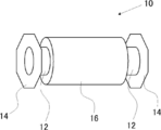
- FIG. 1 is a perspective view showing an embodiment of the assembly of the present invention.
- the assembly 10 is formed by winding a hollow cylindrical winding core 12, a pair of flange members 14 fixed to both ends of the winding core 12, and a long first sheet described later around the winding core 12. It has a roll 16 of the first sheet.
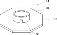
- FIG. 2 shows a perspective view of the flange member 14 shown in FIG.
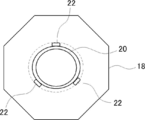
- FIG. 3 shows a top view of the flange member 14.
- the flange member 14 has a substrate (flange) 18, an insertion portion 20 arranged on the substrate 18, and a protrusion 22 arranged on the surface (outer peripheral surface) of the insertion portion 20.
- the insertion portion 20 of the flange member 14 can be inserted into the hollow portion of the hollow cylindrical winding core 12.
- the insertion portion 20 of the flange member 14 is inserted into the hollow portion of the winding core 12, and the protrusion 22 of the insertion portion 20 comes into contact with the inner peripheral surface of the winding core 12, so that the winding core 12 and the flange The member 14 is fixed.
- each member will be described in detail.
- the first sheet is wound around the winding core 12.
- the material of the winding core 12 include plastic, paper, wood, and metal. Of these, paper is preferable because the fixing strength between the winding core and the flange member can be appropriately adjusted. Examples of the paper include paper tube base paper and resin-impregnated paper.
- the size of the winding core 12 is not particularly limited, but the outer diameter (outer diameter of the winding core) is preferably 50 to 350 mm, more preferably 85 to 90 mm. When the winding core has a shape other than a cylindrical shape, the outer diameter corresponds to the diameter of the circumscribed circle of the winding core.
- the inner diameter of the cylindrical winding core 12 is preferably 45 to 345 mm, more preferably 80 to 85 mm.
- the winding core 12 has a hollow cylindrical shape in FIG. 1, the shape is not limited to the shape as long as the first sheet can be wound.
- the winding core may be a polygonal columnar shape. Further, the winding core may be in a solid state.
- the flange member 14 is fixed to both ends of the winding core 12. As described above, in FIG. 1, the winding core 12 and the flange member 14 are fixed by the protrusion 22 in the flange member 14 coming into contact with the inner peripheral surface of the winding core 12.
- Examples of the material of the flange member 14 include plastic, paper, wood, and metal. Of these, plastic is preferable. Examples of the plastic include polypropylene, polyethylene, and polyethylene terephthalate, and polypropylene is preferable.
- the insertion portion 20 and the protrusion 22 described later are also preferably made of the above materials.
- the flange member 14 includes a substrate 18.
- the substrate 18 has an octagonal shape, but the shape is not particularly limited, and may be a circular shape or a polygonal shape other than the octagonal shape (for example, a hexagonal shape). ..
- the thickness of the substrate 18 is not particularly limited, but is preferably 1 to 50 mm, more preferably 2 to 20 mm.
- the size of the substrate 18 is not particularly limited, but it is usually preferable that the size of the substrate 18 is larger than the outer diameter of the roll 16 of the first sheet.
- the size of the substrate 18 means the diameter of the circumscribed circle of the substrate 18.
- the size of the substrate 18 is preferably 1 mm or more larger than the roll 16 of the first sheet, and more preferably 5 mm or more.
- the upper limit is not particularly limited, but it is often 600 mm or less.
- the flange member 14 has an insertion portion 20 arranged on the substrate 18.
- the insertion portion 20 is a member extending along the normal direction of the substrate 18.
- the length of the insertion portion 20 along the extending direction is not particularly limited, but is preferably 2 to 100 mm, more preferably 20 to 30 mm.
- the insertion portion 20 shown in FIGS. 2 and 3 has a cylindrical shape, but is not limited to this form as long as it can be inserted into the hollow portion of the winding core 12.
- the shape of the insertion portion may be polygonal. ..
- the outer diameter of the insertion portion 20 (the outer diameter of the insertion portion 20) is preferably smaller than the inner diameter of the winding core 12.
- the outer diameter of the insertion portion 20 is preferably 45 to 345 mm, more preferably 80 to 85 mm.
- a protrusion 22 is arranged on the outer peripheral surface of the insertion portion 20.
- the number of protrusions 22 is 3, but the number is not particularly limited and may be 4 or more.
- the number of the protrusions 22 is 3 in that the destruction of the microcapsules is further suppressed even when an impact due to dropping is applied (hereinafter, also simply referred to as “the point where the effect of the present invention is more excellent”). More than four are preferable, and four or more are more preferable.
- the upper limit is not particularly limited, and in many cases, the number is 100 or less.
- the three protrusions 22 are arranged at equal intervals on the outer peripheral surface of the insertion portion 20.
- the arrangement position of the protrusions is not limited to the embodiment shown in FIG. 3, but when there are a plurality of protrusions, it is preferable that the plurality of protrusions are arranged at equal intervals on the outer peripheral surface of the insertion portion.
- the three protrusions 22 are arranged so as to be in contact with the substrate 18.
- the relationship between the distance between the protrusion and the substrate is not limited to the embodiment shown in FIG. 3, but it is preferable that the distance between the plurality of protrusions and the substrate is the same. That is, it is preferable that the distance between the protrusion and the substrate is the same in each protrusion.
- the shape of the protrusion 22 is rectangular, but the shape is not particularly limited.
- the height of the protrusion 22 (height from the outer peripheral surface of the insertion portion 20) is not particularly limited, and when the insertion portion 20 is inserted into the hollow portion of the winding core 12, the protrusion is projected on the inner peripheral surface of the winding core 12.
- the height is not particularly limited as long as the height is such that the portions 22 come into contact with each other. Among them, 0.1 to 5 mm is preferable, 0.5 to 2 mm is more preferable, and 0.5 to 1.5 mm is further preferable.
- the height of the protrusion may be constant or may differ depending on the position. For example, in that the effect of the present invention is more excellent, the height of the protrusion may be lowered toward the end of the protrusion in the direction orthogonal to the direction in which the protrusion extends.
- the width in the direction orthogonal to the extending direction of the protrusion 22 is not particularly limited, but is preferably 1 to 25 mm, more preferably 5 to 10 mm.
- the flange member is not limited to the form shown in FIGS. 2 and 3, and for example, as shown in FIG. 4, the substrate 180 included in the flange member 140 may be provided with a hole 40. By passing a finger through the hole 40, the assembly can be easily carried without dropping. In FIG. 4, eight holes 40 are provided, but the number thereof is not particularly limited and may be one or a plurality.
- the roll 16 of the first sheet is a wound product made of the first sheet, which is formed by winding the first sheet around the winding core.
- the first sheet has a long shape.
- the elongated shape means that the length in the longitudinal direction is longer than the length in the lateral direction.
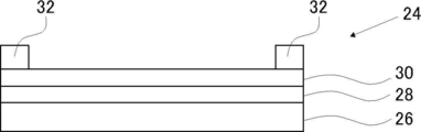
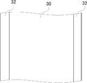
- FIG. 5 shows a cross-sectional view in the width direction of one embodiment of the first sheet
- FIG. 6 shows a top view of the first sheet of FIG.
- the first sheet 24 shown in FIGS. 5 and 6 has a support 26, an adhesion layer 28 arranged on the support 26, and a first layer 30 arranged on the adhesion layer 28.
- a pair of spacers 32 are arranged on the first sheet 24. As shown in FIGS.
- the pair of spacers 32 are arranged apart from each other in the width direction of the first sheet 24.
- the support located on the opposite side of the first layer 30 and the winding core side of the first layer 30 due to the presence of the spacer 32.
- the assembly further has a pair of spacers arranged between the first sheets of the rolls of the first sheet and spaced apart in the width direction of the first sheet.
- the present invention is not limited to this form, and the first sheet may not include the adhesion layer.
- the spacer 32 is arranged on the first sheet 24 shown in FIGS. 5 and 6, the present invention is not limited to this embodiment, and the assembly may not include the spacer.
- the rigidity of the first sheet in the width direction is 150 mN or more. Among them, 153 mN or more is preferable, 165 mN or more is more preferable, 170 mN or more is further preferable, and 175 mN or more is particularly preferable, in that the effect of the present invention is more excellent.
- the rigidity of the first sheet in the width direction is 165 mN or more, the microcapsules are broken even in the first sheet having the first layer containing the fragile microcapsules corresponding to the micro pressure that develops color at 0.2 MPa or less. Hateful.
- the rigidity of the first sheet in the width direction is 175 mN or more, even the first sheet having the first layer containing the more fragile microcapsules corresponding to the ultrafine pressure that develops color at 0.05 MPa or less is microcapsules. Is hard to break.
- the upper limit is not particularly limited, but in many cases it is 500 mN or less.
- the rigidity of the first sheet in the longitudinal direction is not particularly limited, but 180 mN or less is preferable, and 170 mN or less is more preferable, in that the effect of the present invention is more excellent.
- the lower limit is not particularly limited, but from the viewpoint of manufacturing suitability, 100 mN or more is preferable, and 130 mN or more is more preferable.
- the rigidity in the width direction of the first sheet is preferably larger than the rigidity in the longitudinal direction of the first sheet in that the effect of the present invention is more excellent.
- the ratio of the rigidity of the first sheet in the width direction (rigidity in the width direction / rigidity in the longitudinal direction) to the rigidity in the longitudinal direction of the first sheet is not particularly limited, and is often 0.90 or more, which is an effect of the present invention. 1.00 or more is preferable, 1.20 or more is more preferable, and 1.22 or more is further preferable.
- the upper limit is not particularly limited, but it is often 1.50 or less, and more often 1.40 or less.
- the method for measuring the rigidity is as follows. From the first sheet, test pieces of 200 mm in the longitudinal direction (longitudinal direction) and 15 mm in the width direction (horizontal direction) were cut out, and using LOOP STIFFNESS TESTER (manufactured by Toyo Seiki Seisakusho), the cut out test pieces were cut out in the longitudinal direction and the width direction. Measure stiffness.
- the measurement conditions are a clamp interval distance of 100 mm, a loop length of 85 mm, and a compression speed of 3.3 mm / sec.
- the above measurement was performed on two test pieces, and the average value of the longitudinal rigidity obtained from the two test pieces was defined as the longitudinal rigidity of the first sheet, and the average of the widthwise rigidity obtained from the two test pieces was taken.
- the value is the rigidity in the width direction of the first sheet.
- the rigidity of the first sheet in the width direction and the longitudinal direction can be appropriately adjusted depending on the type of the member constituting the first sheet, the manufacturing method of the first sheet, and the like.
- the rigidity of the first sheet can be adjusted.
- the rigidity of the first sheet can be adjusted by adjusting the presence / absence of particles, the type of particles, the hardness of the particles, the size of the particles, and the amount of the particles contained in the resin base material.
- the rigidity of the first sheet can be adjusted by adjusting the procedure of the stretching treatment when the first sheet is manufactured. Further, by adjusting the type of the resin base material to be used and the manufacturing conditions, the rigidity of the resin base material can be adjusted, and as a result, the rigidity of the first sheet can be adjusted.
- each member (resin base material, adhesion layer, first layer, spacer) will be described in detail.
- the first sheet contains an elongated resin base material.
- the resin base material is a member for supporting the first layer.
- the long resin base material means a resin base material whose length in the longitudinal direction is longer than the length in the lateral direction.
- the width of the resin base material is not particularly limited, but is often 50 to 1500 mm, preferably 50 to 500 mm.
- the resin base material is not particularly limited as long as the first sheet satisfies the characteristics of predetermined rigidity, but is not particularly limited, but is a polyester film such as polyethylene terephthalate film, a cellulose derivative film such as cellulose triacetate, and a polyolefin film such as polypropylene and polyethylene. , And polystyrene film.
- the thickness of the resin base material is not particularly limited, but 10 to 200 ⁇ m is preferable from the viewpoint that the effect of the present invention is more excellent.
- the resin base material preferably contains particles in that the rigidity of the first sheet in the width direction is 150 mN or more and that the roll-shaped sheet transportability is improved.
- the particles include calcium carbonate particles, calcium phosphate particles, silica particles, crystalline glass filler particles, kaolin particles, talc particles, titanium dioxide particles, alumina particles, silica-alumina composite oxide particles, barium sulfate particles, and calcium fluoride particles.
- Inorganic particles such as lithium fluoride particles, zeolite particles, molybdenum sulfide particles, and mica particles; polystyrene particles, acrylic resin particles, methyl methacrylate-based particles, benzoguanamine / formaldehyde condensate particles, melamine / formaldehyde condensate particles, and , Organic particles such as polytetrafluoroethylene particles.
- the resin base material is appropriately selected so that the first sheet exhibits a predetermined rigidity. Further, the rigidity in the longitudinal direction and the width direction of the resin base material can be adjusted by controlling the manufacturing conditions when the resin base material is manufactured by a known method (extrusion molding).
- a method for producing a resin base material a step of stretching an unstretched film (for example, biaxial stretching) may be included. Further, the method for producing the resin base material may include a heat fixing step and a heat relaxation step. Further, as a method for producing a resin base material, the methods described in paragraphs 0063 to 0125 of JP2011-208125A can be applied.
- the resin base material in the present invention does not contain coarse particles, foreign substances, defects, precipitates and the like. More coarse grain diameter 5 [mu] m, the number of foreign substances and defects is preferably 50/10 mm 2 or less, more preferably 10/10 mm 2 or less.
- the adhesion layer is a layer for improving the adhesion between the resin base material and the first layer.
- the adhesion layer is preferably a resin layer containing a resin
- the material of the capsule wall of the microcapsules is made of resin
- the adhesion layer is a resin layer containing resin. Is preferable.
- the microcapsules may aggregate with each other when the composition having microcapsules is applied and dried.
- the adhesion layer is a resin layer, as shown in FIG.
- the microcapsules 34 of the first layer 30 interact with the adhesion layer 28 on the resin base material 26, so that aggregation of the microcapsules 34 is suppressed.
- the material constituting the adhesion layer is not particularly limited, and examples thereof include styrene butadiene resin, styrene (meth) acrylic resin, (meth) acrylic resin, olefin resin, urethane resin, polyester resin, and polyvinyl alcohol resin. Of these, styrene-butadiene resin, styrene (meth) acrylic resin, or (meth) acrylic resin is more preferable because the adhesion between the resin base material and the first layer is more excellent.
- the adhesive layer preferably contains a resin having a repeating unit derived from styrene or a derivative thereof, in that the effect of the present invention is more excellent.
- the material of the capsule wall of the microcapsule has an aromatic structure
- the color-developing graininess becomes better when the adhesion layer has an aromatic structure.
- the resin having a repeating unit derived from styrene or a derivative thereof may contain a repeating unit other than the repeating unit derived from styrene or a derivative thereof.
- the content of the repeating unit derived from styrene or its derivative in the resin having the repeating unit derived from styrene or its derivative is not particularly limited, but is preferably 5 to 100% by mass with respect to all the repeating units.
- the styrene derivative means a compound in which a substituent (for example, an alkyl group, an alkoxy group, a carboxyl group, a halogen atom) is substituted at the alpha, ortho, meta or para position of styrene.
- the thickness of the adhesion layer is not particularly limited, but the lower limit is often 0.01 ⁇ m or more, and 0.04 ⁇ m or more is preferable because the effect of the present invention is more excellent.
- the upper limit is often 5 ⁇ m or less, preferably 3 ⁇ m or less in that the effect of the present invention is more excellent, and more preferably 2.0 ⁇ m or less in that the color-developing graininess when used as a pressure measurement sheet is more excellent.
- the adhesion layer may have a single-layer structure or a multi-layer structure. When the adhesion layer has a multi-layer structure, the total thickness of the adhesion layer is preferably within the above range. Further, the adhesion layer may contain a material other than the above-mentioned resin.
- Other materials include, for example, inorganic particles and organic particles.
- the inorganic particles and organic particles include the same particles that may be contained in the resin base material described above.
- the particles may be particles having an antistatic ability.
- a plurality of types of particles may be used, and the particles may be contained in both the resin base material and the adhesion layer. From the viewpoint that the effect of the present invention is more excellent, it is preferable that at least one of the resin base material and the adhesion layer contains particles. Since at least one of the resin base material and the adhesion layer contains particles, it is easy to adjust the rigidity of the first sheet in the width direction to 150 mN or more.
- the particle size of the particles contained in either the resin base material or the adhesion layer is large.
- the proportion of inorganic particles having a particle size of 1 ⁇ m or more in the entire inorganic particles is preferably 50% by volume or more, and more preferably the proportion of inorganic particles having a particle size of 10 ⁇ m or more is 50% by volume or more.
- the proportion of the inorganic particles having a particle size of 1 ⁇ m or more and the proportion of the inorganic particles having a particle size of 10 ⁇ m or more in the entire inorganic particles are as follows. Ask. By firing the resin base material (when it has an adhesion layer, the resin base material and the adhesion layer, the same applies hereinafter), at least a part of the resin is decomposed and removed from the resin base material to leave inorganic particles. Disperse the remaining inorganic particles in ethanol.
- a laser diffraction particle size distribution measuring device for example, Mastersizer 2000 manufactured by Malvern, laser diffraction / scattering type particle size distribution measuring device LA-920 manufactured by HORIBA, Ltd., etc.
- the method for forming the adhesion layer is not particularly limited, and for example, a method of applying the composition for forming the adhesion layer to the resin base material and a method of co-extruding the material for forming the adhesion layer and the material for forming the resin base material. Can be mentioned. Further, as a method for forming the adhesion layer, a method of applying the composition for forming the adhesion layer on the surface of the biaxially stretched resin base material and a resin stretched in the first direction (for example, MD: Machine Direction).
- composition for forming an adhesion layer is applied to the surface of the base material, and then the coating material for forming the adhesion layer is applied in a second direction (for example, TD: Transferse) orthogonal to the first direction along the surface of the resin base material.
- TD Transferse
- a method of stretching together with a resin base material in Direction can also be mentioned.
- the first layer contains microcapsules containing a color former.
- the materials constituting the microcapsules will be described in detail.
- Microcapsules generally have a core portion and a capsule wall for encapsulating a core material (encapsulated (also referred to as an encapsulated component)) forming the core portion.
- the microcapsules contain a color former as a core material (encapsulating component). Since the color-developing agent is encapsulated in the microcapsules, the color-developing agent can exist stably until the microcapsules are destroyed by pressure.
- the microcapsules have a capsule wall that encloses the core material.
- the material (wall material) for the capsule wall of the microcapsules include known resins conventionally used as the wall material for microcapsules containing a color former in the use of pressure-sensitive copying paper or thermal recording paper.
- Specific examples of the resin include polyurethane, polyurea, polyurethane urea, melamine-formaldehyde resin, and gelatin.
- the capsule wall of the microcapsules contains at least one resin selected from the group consisting of polyurethane urea, polyurethane, and polyurea.
- the capsule wall of the microcapsules is substantially made of resin. Being substantially composed of resin means that the content of the resin is 90% by mass or more with respect to the total mass of the capsule wall, and 100% by mass is preferable. That is, the capsule wall of the microcapsules is preferably made of resin.
- the polyurethane is a polymer having a plurality of urethane bonds, and is preferably a reaction product formed from a raw material containing a polyol and a polyisocyanate.
- the polyurea is a polymer having a plurality of urea bonds, and is preferably a reaction product formed from a raw material containing a polyamine and a polyisocyanate.
- the polyurethane urea is a polymer having a urethane bond and a urea bond, and is preferably a reaction product formed from a raw material containing a polyol, a polyamine, and a polyisocyanate.
- a part of the polyisocyanate reacts with water to form a polyamine, and as a result, polyurethane urea may be obtained.
- the melamine-formaldehyde resin is preferably a reaction product formed from polycondensation of melamine and formaldehyde.
- the polyisocyanate is a compound having two or more isocyanate groups, and examples thereof include aromatic polyisocyanates and aliphatic polyisocyanates.
- the polyisocyanate may be, for example, an adduct of a polyol such as trimethylolpropane and a bifunctional polyisocyanate.
- the polyol is a compound having two or more hydroxyl groups.
- a low molecular weight polyol eg, an aliphatic polyol or an aromatic polyol.
- a “low molecular weight polyol” has a molecular weight of 400 or less.
- Polyols are intended), polyvinyl alcohols, polyether polyols, polyester polyols, polylactone-based polyols, castor oil-based polyols, polyolefin-based polyols, and hydroxyl group-containing amine-based compounds (for example, amino alcohols.
- hydroxyl group-containing amine-based compounds for example, amino alcohols.
- examples thereof include propylene oxide of an amino compound such as ethylenediamine or an ethyleneoxide adduct, such as N, N, N', N'-tetrax [2-hydroxypropyl] ethylenediamine, etc.).
- the polyamine is a compound having two or more amino groups (primary amino group or secondary amino group), and is, for example, diethylenetriamine, triethylenetetramine, 1,3-propylenediamine, and hexa.
- Aliphatic polyvalent amines such as methylenediamine; epoxy compound adducts of aliphatic polyvalent amines; alicyclic polyvalent amines such as piperazine; 3,9-bis-aminopropyl-2,4,8,10-tetraoxa Examples thereof include heterocyclic diamines such as Spiro- (5,5) undecane.
- the glass transition temperature of the capsule wall of the microcapsule is not particularly limited, but is preferably 50 to 160 ° C, more preferably 80 to 150 ° C.
- the method for measuring the glass transition temperature of the capsule wall is as follows. 50 sheets of the first sheet having a length of 1 cm and a width of 1 cm are prepared, and all of them are immersed in 10 ml of water and allowed to stand for 24 hours to obtain an aqueous dispersion of microcapsules. The obtained aqueous dispersion of microcapsules is centrifuged at 15,000 rpm for 30 minutes, and the microcapsules are separated. Ethyl acetate is added to the separated microcapsules, and the mixture is further stirred at 25 ° C. for 24 hours.
- the obtained solution is filtered, and the obtained residue is vacuum-dried at 60 ° C. for 48 hours to obtain microcapsules containing nothing inside (hereinafter, also simply referred to as “measurement material”). Be done. That is, a capsule wall material of microcapsules, which is a measurement target of the glass transition temperature, can be obtained.
- the thermal decomposition temperature of the obtained measurement material is measured using a thermogravimetric differential thermal analyzer TG-DTA (device name: DTG-60, Shimadzu Corporation).
- the thermal decomposition temperature refers to the temperature of the measurement material raised from room temperature at a constant temperature rise rate (10 ° C./min) with respect to the mass of the measurement material before heating. The temperature at which the weight is reduced by 5% by mass is defined as the thermal decomposition temperature (° C.).
- the glass transition temperature of the measurement material was measured using a differential scanning calorimeter DSC (device name: DSC-60a Plus, Shimadzu Corporation) using a closed pan, and the temperature rise rate was 25 ° C./min. Measure in the range of ° C to (pyrolysis temperature (° C) -5 ° C). As the glass transition temperature of the capsule wall of the microcapsule, the value at the time of raising the temperature in the second cycle is used.
- the average particle size of the microcapsules is not particularly limited, but is preferably 1 to 80 ⁇ m, more preferably 5 to 70 ⁇ m, and even more preferably 10 to 50 ⁇ m in terms of volume-based median diameter (D50).
- the median diameter based on the volume of the microcapsules can be controlled by adjusting the manufacturing conditions of the microcapsules and the like.
- the volume-based median diameter of the microcapsules is the volume of the particles on the large diameter side and the small diameter side when the entire microcapsule is divided into two with the particle diameter at which the cumulative volume is 50% as a threshold. The diameter at which the total is equal. That is, the median diameter corresponds to the so-called D50.
- the average wall thickness of the number of microcapsules (the average wall thickness of the number of capsule walls of the microcapsules) is not particularly limited, but is preferably 0.01 ⁇ m or more and 2 ⁇ m or less, more preferably more than 0.02 ⁇ m and less than 2 ⁇ m, and 0.05 ⁇ m or more. 5 ⁇ m or less is more preferable.
- the wall thickness of the microcapsules refers to the thickness ( ⁇ m) of the capsule wall forming the capsule particles of the microcapsules, and the number average wall thickness is the thickness ( ⁇ m) of the individual capsule walls of the five microcapsules. Is obtained by a scanning electron microscope (SEM) and averaged.
- a cross-sectional section of the first sheet having the first layer containing microcapsules was prepared, and the cross section was observed at 200 times by SEM (value of average particle size of microcapsules) ⁇ 0.
- SEM value of average particle size of microcapsules
- the major axis means the longest diameter when observing the microcapsules.
- the ratio ( ⁇ / Dm) of the number average wall thickness ⁇ of the microcapsules to the average particle size Dm of the microcapsules is not particularly limited, and is often 0.001 or more. Above all, it is preferable to satisfy the relationship of the formula (1) in that the effect of the present invention is more excellent. Equation (1) 0.100> ⁇ / Dm> 0.001 That is, the above ratio ( ⁇ / Dm) is preferably larger than 0.001 and less than 0.100. When the relationship of the equation (1) is satisfied, the color density gradation can be easily recognized according to the pressure.
- a color former is encapsulated in the microcapsules.
- a color former is a compound that develops a color when it comes into contact with a color developer described later from a colorless state.
- an electron-donating dye precursor precursor of a dye that develops color
- the color former an electron-donating colorless dye is preferable.
- the color former those known in the application of pressure-sensitive copying paper or thermal recording paper can be used.
- Examples of the color former include triphenylmethanephthalide compounds, fluorene compounds, phenothiazine compounds, indolylphthalide compounds, azaindrillphthalide compounds, leucooramine compounds, rhodamine lactam compounds, and tris. Examples thereof include phenylmethane-based compounds, diphenylmethane-based compounds, triazene-based compounds, spiropyran-based compounds, and fluorene-based compounds. Examples of the above compounds include the compounds described in JP-A-5-257272, the compounds described in paragraphs 0030 to 0033 of International Publication No. 2009/8248, and 3', 6'-bis (diethylamino) -2- (4).
- the molecular weight of the color former is not particularly limited, and is preferably 300 or more.
- the upper limit is not particularly limited, but is preferably 1000 or less.
- microcapsules may contain components other than the above-mentioned color former.
- microcapsules preferably contain a solvent.
- the solvent is not particularly limited, and for example, an alkylnaphthalene compound such as diisopropylnaphthalene, a diarylalkane compound such as 1-phenyl-1-xsilylethane, an alkylbiphenyl compound such as isopropylbiphenyl, a triarylmethane compound, and an alkylbenzene compound.
- Aromatic hydrocarbons such as benzylnaphthalene compounds, diarylalkylene compounds, and arylindane compounds; aliphatic hydrocarbons such as dibutyl phthalate and isoparaffin; soybean oil, corn oil, cottonseed oil, rapeseed oil, olive oil, Examples thereof include natural animal and vegetable oils such as coconut oil, castor oil, and fish oil, and high-boiling distillates of natural compounds such as mineral oil.
- the mass ratio of the solvent to the color former is preferably in the range of 98/2 to 30/70 in terms of color development.
- the range of 97/3 to 40/60 is more preferable.
- the microcapsules may contain one or more additives such as an ultraviolet absorber, a light stabilizer, an antioxidant, a wax, and an odor suppressant, if necessary.
- additives such as an ultraviolet absorber, a light stabilizer, an antioxidant, a wax, and an odor suppressant, if necessary.
- the method for producing microcapsules is not particularly limited, and examples thereof include known methods such as an interfacial polymerization method, an internal polymerization method, a phase separation method, an external polymerization method, and a core selvation method. Of these, the interfacial polymerization method is preferable.
- the interfacial polymerization method will be described by taking as an example a method for producing microcapsules in which the capsule wall is polyurea or polyurethane urea.
- the interfacial polymerization method is a raw material containing a color former, a solvent having a boiling point of 100 ° C.
- a capsule wall material for example, polyisocyanate and at least one selected from the group consisting of polyols and polyamines.
- a polyamine is produced in a system by reacting isocyanate with water, a polyol and a polyamine may not be used.
- Interfacial weight including (emulsification step) and step of polymerizing the capsule wall material at the interface between the oil phase and the aqueous phase to form a capsule wall to form microcapsules containing a color former (encapsulation step).
- Legal is preferred.
- the mass ratio of the total amount of polyol and polyamine to the amount of polyisocyanate (total amount of polyol and polyamine / amount of polyisocyanate) in the above raw materials is not particularly limited, but is 0.1 / 99.9 to. 30/70 is preferable, and 1/99 to 25/75 is more preferable.
- the type of emulsifier used in the emulsification step is not particularly limited, and examples thereof include a dispersant and a surfactant.
- examples of the dispersant include polyvinyl alcohol.
- the first layer may contain other components (for example, binder, surfactant) in addition to the above-mentioned microcapsules.
- the mass (g / m 2 ) per unit area of the first layer is not particularly limited, but 0.5 to 30 g / m 2 is preferable because the effect of the present invention is more excellent.
- the method for forming the first layer is not particularly limited.
- a method of applying a composition for forming a first layer containing microcapsules on a resin base material (or on an adhesive layer) and heat-treating the obtained coating film at a predetermined temperature or higher can be mentioned. ..
- a mode of heating at a predetermined temperature or higher will be described in detail.
- the composition for forming the first layer preferably contains at least microcapsules and a solvent.
- the microcapsule dispersion obtained by the above-mentioned interfacial polymerization method may be used as the composition for forming the first layer.
- the composition for forming the first layer may contain other components that may be contained in the first layer described above.
- the method of applying the composition for forming the first layer is not particularly limited, and examples of the coating machine used at the time of application include an air knife coater, a rod coater, a bar coater, a curtain coater, a gravure coater, and an extrusion coater. , Die coater, slide bead coater, and blade coater.
- the obtained coating film is heat-treated at a predetermined temperature or higher.
- the optimum temperature is selected according to the material of the capsule wall of the microcapsules used, but 60 ° C. or higher is preferable, and 70 ° C. or higher is preferable because the effect of the present invention is more excellent. More preferred.
- the upper limit is not particularly limited, but it is often 180 ° C. or lower, and 140 ° C. or lower is preferable, and 120 ° C. or lower is more preferable in that the color development density is more excellent.
- the heating time is not particularly limited, but 1.0 to 20 minutes is preferable, and 3.0 to 10 minutes is more preferable, from the viewpoint of more excellent effect of the present invention and productivity.
- the method of forming the first layer on the resin base material has been described above, the method is not limited to the above embodiment, and for example, after the first layer is formed on the temporary support, the first layer is formed.
- the first layer may be transferred onto a resin substrate.
- the temporary support is not particularly limited as long as it is a peelable support.
- the material of the spacer is not particularly limited, but a rubber foam or an elastic foam is preferable.
- the rubber foam include a rubber foam selected from the group consisting of natural rubber, isoprene rubber, styrene rubber, nitrile rubber, butadiene rubber, chloroprene rubber, and urethane rubber.
- the elastic foam include an elastic foam selected from the group consisting of polyethylene, polypropylene, polystyrene, polyvinyl chloride, and polyvinyl acetate.
- the thickness of the spacer is not particularly limited, but is preferably thicker than that of the first layer.
- the thickness of the spacer is often 1 to 10 mm, and is preferably 1 to 5 mm, more preferably 2.5 to 5 mm, in that the effect of the present invention is more excellent.
- the coefficient of static friction of the spacer is not particularly limited, but 0.1 to 1.0 is preferable because the effect of the present invention is more excellent.
- the coefficient of kinetic friction of the spacer is not particularly limited, but 0.1 to 1.0 is preferable because the effect of the present invention is more excellent.
- the method of arranging the spacer on the first sheet is not particularly limited, and examples thereof include a method of using double-sided tape and a method of using an adhesive or an adhesive.
- the arithmetic mean roughness Ra of the first sheet is not particularly limited, and is often 0.1 ⁇ m or more, and is preferably 2.5 to 7.0 ⁇ m in that the color density is more excellent.
- the arithmetic mean roughness Ra of the first sheet is intended to be the arithmetic average roughness Ra of the surface of the first sheet facing the second sheet (contacting side) when using the pressure measurement sheet set. do.
- the arithmetic mean roughness Ra is the arithmetic mean roughness of the surface of the first layer opposite to the resin base material side. It corresponds to Ra.
- the arithmetic mean roughness Ra in the present specification (the arithmetic average roughness Ra on the first sheet and the arithmetic average roughness Ra on the second sheet described later) is the arithmetic defined in JIS B 0681-6: 2014. It means the average roughness Ra.
- a scanning white interferometer using an optical interferometry method (specifically, NewView 5020 manufactured by Zygo; objective lens ⁇ 50 times; intermediate lens ⁇ 0.5 times) is used.
- the measurement mode when measuring the arithmetic mean roughness Ra of the first sheet using the scanning white interferometer is the Stich mode
- the measurement mode when measuring the arithmetic mean roughness Ra of the second sheet is the Micro mode. Is.
- the insertion portion 20 of the flange member 14 is inserted into the hollow portion of the winding core 12 to fix both, but the fixing method is not limited to this embodiment. ..
- the fixing method is not limited to this embodiment. ..
- the winding core and the flange member may be fixed by the portion in contact with the flange member.
- a fixing method other than the method using the protrusion may be used.
- the winding core and the flange member may be adhered and fixed with an adhesive. Further, the winding core and the flange member may be screwed together.
- the assembly of the present invention may be encapsulated in a package. It may be a bag, or it may be a container including a container body having an opening and a lid for closing the opening.
- the material constituting the package is not particularly limited, and examples thereof include resins, and more specifically, polyolefin resins, polyethylene resins, and polypropylene resins.
- the color of the package is not particularly limited, and examples thereof include transparent color, brown, and black. Among them, brown or black is preferable, and black is more preferable, in terms of light resistance.
- the assembly of the present invention may be combined with a second sheet having a second layer containing a color developer to form a sheet set for pressure measurement.
- the second sheet may be treated as an assembly. That is, the pressure measurement sheet set of the present invention has a first layer including a winding core, a pair of flange members fixed to both ends of the winding core, and microcapsules wound around the winding core and containing a color former.
- the first sheet and the second sheet are laminated so that the first layer in the first sheet and the second layer in the second sheet face each other. ..
- the microcapsules are broken in the pressurized region, and the color-developing agent contained in the microcapsules comes out from the microcapsules, and the color-developing agent in the second layer is combined with the color-developing agent.
- the color reaction progresses between them. As a result, color development progresses in the pressurized region.
- the second sheet has a second layer containing a color developer.
- the second sheet preferably includes a support and a second layer arranged on the support. In the following, each member will be described in detail.
- the support is a member for supporting the second layer. If the second layer itself can be handled, the second sheet does not have to have a support.
- the support may have either a sheet shape or a plate shape. Examples of the support include a resin base material and synthetic paper, and a resin base material is preferable. Examples of the mode of the resin base material include the mode of the resin base material contained in the first sheet described above. Further, as the support, the mode of the laminate of the resin base material and the adhesion layer described in the first sheet described above can also be mentioned. The preferred embodiments of the resin base material and the adhesive layer are as described above.
- the support on the first sheet and the support on the second sheet may be the same or different.
- the support in the second sheet is preferably transparent, and the haze of the support is preferably 0 to 20%, more preferably 0 to 10%, from the viewpoint that the color development state after the pressure measurement can be easily visually recognized through the support. preferable.
- the second layer is a layer containing a color developer.
- the color developer is a compound that does not have a color-developing function by itself, but has a property of causing the color-developing agent to develop color when it comes into contact with the color-developing agent.
- an electron-accepting compound is preferable.
- the color developer include inorganic compounds and organic compounds, and the inorganic compounds and organic compounds described in paragraphs 0055 to 0056 of International Publication No. 2009/008248 are preferable. Acidic clay, activated clay, or a metal salt of an aromatic carboxylic acid is preferable in that the color density and the image quality after color development are more excellent.
- the content of the color developer in the second layer is not particularly limited, but is preferably 20 to 95% by mass and more preferably 30 to 90% by mass with respect to the total mass of the second layer in that the color development concentration is more excellent. ..
- the content of the color developer in the second layer is not particularly limited, but is preferably 0.1 to 30 g / m 2.
- the content of the developer is preferably 3 to 20 g / m 2 and more preferably 5 to 15 g / m 2 .
- the content of the developer is preferably 0.1 to 5 g / m 2 , more preferably 0.2 to 3 g / m 2 .
- the second layer may contain components other than the above-mentioned developer.
- Other components include, for example, polymer binders, pigments, optical brighteners, defoamers, penetrants, UV absorbers, surfactants, and preservatives.
- the polymer binder include styrene-butadiene copolymer, polyvinyl acetate, polyacrylic acid ester, polyvinyl alcohol, polyacrylic acid, maleic anhydride-styrene copolymer, olefin resin, and modified acrylic acid ester copolymer.
- the pigment include heavy calcium carbonate, light calcium carbonate, talc, titanium dioxide and the like.
- the thickness of the second layer is not particularly limited, but 1 to 50 ⁇ m is preferable, and 2 to 30 ⁇ m is more preferable, because the effect of the present invention is more excellent.
- the mass (g / m 2 ) per unit area of the second layer is not particularly limited, but 0.5 to 30 g / m 2 is preferable because the effect of the present invention is more excellent.
- the method for forming the second layer is not particularly limited.
- a method of applying a composition for forming a second layer containing a color developer on a support and, if necessary, subjecting the obtained coating film to a drying treatment can be mentioned.
- the composition for forming the second layer may be a dispersion liquid in which a color developer is dispersed in water or the like.
- the dispersion liquid in which the developer is dispersed can be prepared by mechanically dispersing the inorganic compound in water.
- the color developer is an organic compound, it can be prepared by mechanically dispersing the organic compound in water or dissolving it in an organic solvent.
- the composition for forming the second layer may contain other components that may be contained in the second layer described above.
- the method for applying the composition for forming the second layer is not particularly limited, and examples thereof include a method using a coating machine used for applying the composition for forming the first layer described above.
- the coating film After applying the composition for forming the second layer on the support, the coating film may be subjected to a drying treatment, if necessary.
- a drying treatment include heat treatment.
- the method of forming the second layer on the support has been described above, the method is not limited to the above embodiment.
- the temporary support is peeled off.
- a second sheet composed of the second layer may be formed.
- the temporary support is not particularly limited as long as it is a peelable support.
- the second sheet may have a support other than the above-mentioned support and the second layer.
- the second sheet may have an adhesion layer between the support and the second layer to enhance the adhesion between the two.
- the aspect of the adhesion layer include the aspect of the adhesion layer that the first sheet described above may have.
- the first sheet and the second sheet are laminated by laminating the first sheet and the second sheet so that the first layer of the first sheet and the second layer of the second sheet face each other. It is used by obtaining a body and pressurizing the laminate. That is, the first sheet corresponds to the sheet used for measuring the pressure together with the second sheet.
- the arithmetic mean roughness Ra of the second sheet is preferably 1.2 ⁇ m or less in that the color density is more excellent.
- the arithmetic mean roughness Ra of the second sheet is intended to be the arithmetic average roughness Ra of the surface of the second sheet facing the first sheet (contacting side) when using the pressure measurement sheet set. do.
- the arithmetic mean roughness Ra is the arithmetic mean roughness Ra on the surface opposite to the support side of the second layer. Corresponds to.
- Example 1 A long polyethylene terephthalate film (PET film) (width 450 mm) having a thickness of 75 ⁇ m, which was subjected to corona discharge treatment on both sides after biaxial stretching, was prepared. Next, the composition A for forming an adhesion layer, which will be described later, was applied to one surface of the obtained PET film with a bar coater and dried to form an adhesion layer A having a thickness of 0.45 ⁇ m.
- PET film polyethylene terephthalate film
- composition of the adhesion layer forming composition A is as follows.
- the mass of each dispersion was expressed as "parts by mass” when the total mass of the composition was 100 parts by mass.
- the adhesion layer forming composition B having the following composition was applied onto the adhesion layer A by a bar coater and dried to form a adhesion layer B having a thickness of 0.1 ⁇ m to obtain a support 1.
- a coloring agent 3,3-bis (2-methyl-1-octyl-3-indrill) phthalide (18 parts by mass) was dissolved in diarylethane (70 parts by mass) to obtain Solution A. Further, a butylene oxide adduct (0.4 parts by mass) of ethylenediamine dissolved in methyl ethyl ketone (1 part by mass) was added to the stirring solution A to obtain a solution B. Further, a trimethylolpropane adduct (2 parts by mass) of tolylene diisocyanate dissolved in methyl ethyl ketone (1 part by mass) was added to the stirring solution B to obtain a solution C.
- the above solution C was added to a solution in which polyvinyl alcohol (6 parts by mass) was dissolved in water (150 parts by mass), and the solution was emulsified and dispersed.
- Water (300 parts by mass) was added to the emulsion after emulsification and dispersion, and the mixture was heated to 70 ° C. with stirring, stirred for 1 hour and then cooled to prepare a microcapsule solution containing microcapsules containing a color former. ..
- the average particle size of the obtained microcapsules was 20 ⁇ m.
- the prepared microcapsule liquid was used as a color former-encapsulating microcapsule liquid (A).
- the protective ear layers are formed on both ends of the support 1 in the width direction on the close contact layer B of the support 1, and the first layer is formed between the protective ear layers.
- the above-mentioned color-developing agent-encapsulating microcapsule solution (A) is applied onto the surface of the support 1 having a width of 450 mm on the adhesion layer B side, and then the protective ear layer forming composition is applied so as to be in contact with both ends in the width direction. After that, it was dried to obtain a sheet.
- the width of the first layer was 400 mm
- the width of the protective ear layer was 25 mm on one side (50 mm on both sides).
- the central portion of the sheet was cut to a width of 360 mm using a processing machine so as to remove the protective ear layers located at both ends in the width direction of the obtained sheet, and placed on the support 1 and the support 1.
- a long first sheet having the first layer was obtained.
- the following double-sided tape is attached to both end edges in the width direction on the obtained first sheet, the following cushion (spacer) is attached, and spacers are arranged in the entire area in the longitudinal direction as shown in FIGS. 5 and 6.
- the first sheet was prepared.
- a hollow cylindrical winding core described later and a flange member described later were prepared.
- the flange member had a substrate and a cylindrical insertion portion arranged on the substrate, and a protrusion was arranged on the surface of the insertion portion (see FIGS. 2 and 3).
- the insertion portion of the flange member was inserted into the hollow portion of the winding core, and the flange members were fixed to both ends of the winding core to prepare a winding core with a flange member.
- the first sheet on which the spacer is arranged is wound around the winding core of the winding core with a flange member, and the assembly 1 as shown in FIG. 1 having a cross-sectional diameter (outer diameter of the roll of the first sheet) at both ends is 170 mm.
- Neoprene foam rubber manufactured by Tokiwa Rubber Co., Ltd.
- Width 15 mm
- Thickness 5 mm
- Static friction coefficient 0.63
- Dynamic friction coefficient 0.62 -Double-sided tape- Japanese paper + acrylic adhesive (Sekisui Chemical Co., Ltd., double tack tape # 595)
- width 10 mm -Winding core- Made of paper (impregnated with resin)
- length 390 mm
- inner diameter of hollow part 76 mm -Flange member (see Fig.
- composition C for forming an adhesive layer was applied to both surfaces of a long polyethylene terephthalate film (PET film) having a thickness of 75 ⁇ m uniaxially stretched in the longitudinal direction and dried. Next, it was stretched in the width direction, heat-fixed and heat-relaxed to obtain a support 4.
- PET film polyethylene terephthalate film
- 1% aqueous solution (80 parts by mass) of sodium carboxymethyl cellulose (Daiichi Kogyo Seiyaku, Cellogen EP), 15% aqueous solution (18 parts by mass) of Na alkylbenzene sulfonate (Daiichi Kogyo Seiyaku, Neogen T), 1% aqueous solution (20 parts by mass) of polyoxyethylene polyoxypropylene lauryl ether (Daiichi Kogyo Seiyaku, Neugen LP-70), sodium-bis (3,3,4,4,5,5,6,6) , 6-Nonafluorohexyl) -2-Sulfinatooxysuccinate (Fujifilm, W-AHE) 1% aqueous solution (20 parts by mass) is mixed to prepare a composition for forming a second layer containing a clay substance.
- the composition for forming the second layer was applied onto the support 1 so that the solid content coating amount was 7 g / m 2 . Then, the obtained coating film was dried to form a second layer, and a second sheet was obtained.
- the haze of the support 1 was 10% or less.
- the above measurement was performed on two test pieces, and the average value of the longitudinal rigidity obtained from the two test pieces was defined as the longitudinal rigidity of the first sheet, and the average of the widthwise rigidity obtained from the two test pieces was taken. The value was taken as the rigidity of the first sheet in the width direction.
- a test piece cut out so that the longitudinal direction of the test piece is along the longitudinal direction of the first sheet is used, and the rigidity in the width direction of the first sheet is measured.
- a test piece cut out so that the longitudinal direction of the test piece was along the width direction of the first sheet was used.
- the first sheet included in each assembly and the second sheet cut into a size of 5 cm in length ⁇ 5 cm in width are arranged so that the surface of the first layer of the first sheet and the surface of the second layer of the second sheet face each other. Overlaid. Both of the stacked sheets were placed on a desk sandwiched between two glass plates having a smooth surface, and a weight was placed on the glass plates to pressurize the sheets at a pressure of 0.2 MPa to develop a color. Then, the color-developed surface of the second sheet that developed color was visually observed from the support (PET sheet) surface side via the support, and evaluated according to the following evaluation criteria. The sample of Comparative Example 1 was not evaluated because the capsule was destroyed in the drop test. The evaluation results are shown in Table 1. A: The graininess on the color-developing surface is very small. B: There is some graininess on the colored surface, but there is no problem in practical use. C: The graininess on the color-developing surface is clearly large.
- Example 12 From a comparison between Example 12 and other Examples, it was confirmed that when the thickness of the adhesion layer is 2.0 ⁇ m or less, an excellent effect can be obtained due to the color-developing graininess. Further, from the comparison between Example 14 and other Examples, it was confirmed that when there is an adhesive layer, a more excellent effect can be obtained and the color-developing graininess is excellent.
- Example 16 N, N, N', N'-tetrakis (2-hydroxypropyl) ethylenediamine dissolved in synthetic isoparaffin (Idemitsu Kosan Co., Ltd., IP solvent 1620) (15 parts by mass), ethyl acetate (3 parts by mass) ) Adeca, Adecapolyether EDP-300) (0.4 parts by mass) is added to agitated 1-phenyl-1-xylylethane (Shin Nihon Petroleum Co., Ltd., Hysol SAS296) (78 parts by mass) to a solution. I got D.
- a trimethylolpropane adduct (DIC Corporation, Burnock D-750) (3 parts by mass) of trimethylolpropane dissolved in ethyl acetate (7 parts by mass) is added to the stirring solution D to prepare a solution. E was obtained. Then, the above solution E was added to a solution in which polyvinyl alcohol (PVA-205, Kuraray Co., Ltd.) (69 parts by mass) was dissolved in water (140 parts by mass), and the mixture was emulsified and dispersed. Water (340 parts by mass) was added to the emulsion after emulsification and dispersion, and the mixture was heated to 70 ° C. with stirring, stirred for 1 hour, and then cooled. Further, water was added to adjust the concentration to obtain a color former-free microcapsule solution (B) having a solid content concentration of 19.6%.
- Color-developing agent-encapsulating microcapsule solution (A) (18 parts by mass), color-developing non-encapsulating microcapsule solution (B) (2 parts by mass), water (63 parts by mass), carboxymethyl cellulose Na (Daiichi Kogyo Seiyaku Seiyaku) Co., Ltd., 10% aqueous solution of cellogen 5A (1.8 parts by mass), 1% aqueous solution of carboxymethyl cellulose Na (Daiichi Kogyo Seiyaku Co., Ltd., cellogen EP) (30 parts by mass), sodium alkylbenzene sulfonate (No.
- the assembly 16 was prepared according to the same procedure as in Example 1 above, except that the PET film used was changed by using the above-mentioned specific composition instead of the color-developing agent-encapsulating microcapsule solution (A).
Landscapes
- Chemical & Material Sciences (AREA)
- Engineering & Computer Science (AREA)
- Materials Engineering (AREA)
- Wood Science & Technology (AREA)
- Organic Chemistry (AREA)
- Life Sciences & Earth Sciences (AREA)
- General Physics & Mathematics (AREA)
- Physics & Mathematics (AREA)
- Inorganic Chemistry (AREA)
- Laminated Bodies (AREA)
- Winding Of Webs (AREA)
- Adhesive Tapes (AREA)
- Storage Of Web-Like Or Filamentary Materials (AREA)
- Color Printing (AREA)
- Manufacturing Of Micro-Capsules (AREA)
Priority Applications (4)
| Application Number | Priority Date | Filing Date | Title |
|---|---|---|---|
| KR1020227029976A KR102689167B1 (ko) | 2020-02-25 | 2021-01-26 | 조립체, 압력 측정용 시트 세트, 시트 |
| JP2021573715A JP7480187B2 (ja) | 2020-02-25 | 2021-01-26 | 組立体、圧力測定用シートセット、シート |
| CN202180016469.2A CN115151499A (zh) | 2020-02-25 | 2021-01-26 | 组装体、压力测定用片材组、片材 |
| JP2022171613A JP2023011737A (ja) | 2020-02-25 | 2022-10-26 | 組立体、圧力測定用シートセット、シート |
Applications Claiming Priority (2)
| Application Number | Priority Date | Filing Date | Title |
|---|---|---|---|
| JP2020029387 | 2020-02-25 | ||
| JP2020-029387 | 2020-02-25 |
Publications (1)
| Publication Number | Publication Date |
|---|---|
| WO2021171867A1 true WO2021171867A1 (ja) | 2021-09-02 |
Family
ID=77490917
Family Applications (1)
| Application Number | Title | Priority Date | Filing Date |
|---|---|---|---|
| PCT/JP2021/002550 Ceased WO2021171867A1 (ja) | 2020-02-25 | 2021-01-26 | 組立体、圧力測定用シートセット、シート |
Country Status (5)
| Country | Link |
|---|---|
| JP (2) | JP7480187B2 (enExample) |
| KR (1) | KR102689167B1 (enExample) |
| CN (1) | CN115151499A (enExample) |
| TW (1) | TWI867158B (enExample) |
| WO (1) | WO2021171867A1 (enExample) |
Citations (3)
| Publication number | Priority date | Publication date | Assignee | Title |
|---|---|---|---|---|
| JP2009174991A (ja) * | 2008-01-24 | 2009-08-06 | Fujifilm Corp | 圧力測定シート |
| JP2009173307A (ja) * | 2008-01-24 | 2009-08-06 | Fujifilm Corp | 圧力測定シート |
| JP2013169713A (ja) * | 2012-02-21 | 2013-09-02 | Dainippon Printing Co Ltd | 赤外線抑制フィルム |
Family Cites Families (2)
| Publication number | Priority date | Publication date | Assignee | Title |
|---|---|---|---|---|
| JP2009014493A (ja) * | 2007-07-04 | 2009-01-22 | Fujifilm Corp | 圧力測定用材料 |
| JP2015039847A (ja) * | 2013-08-22 | 2015-03-02 | 大日本印刷株式会社 | シール型熱転写受像シート |
-
2021
- 2021-01-26 WO PCT/JP2021/002550 patent/WO2021171867A1/ja not_active Ceased
- 2021-01-26 KR KR1020227029976A patent/KR102689167B1/ko active Active
- 2021-01-26 CN CN202180016469.2A patent/CN115151499A/zh active Pending
- 2021-01-26 JP JP2021573715A patent/JP7480187B2/ja active Active
- 2021-02-17 TW TW110105204A patent/TWI867158B/zh active
-
2022
- 2022-10-26 JP JP2022171613A patent/JP2023011737A/ja not_active Abandoned
Patent Citations (3)
| Publication number | Priority date | Publication date | Assignee | Title |
|---|---|---|---|---|
| JP2009174991A (ja) * | 2008-01-24 | 2009-08-06 | Fujifilm Corp | 圧力測定シート |
| JP2009173307A (ja) * | 2008-01-24 | 2009-08-06 | Fujifilm Corp | 圧力測定シート |
| JP2013169713A (ja) * | 2012-02-21 | 2013-09-02 | Dainippon Printing Co Ltd | 赤外線抑制フィルム |
Also Published As
| Publication number | Publication date |
|---|---|
| KR20220133989A (ko) | 2022-10-05 |
| TWI867158B (zh) | 2024-12-21 |
| JP2023011737A (ja) | 2023-01-24 |
| KR102689167B1 (ko) | 2024-07-26 |
| CN115151499A (zh) | 2022-10-04 |
| TW202200382A (zh) | 2022-01-01 |
| JPWO2021171867A1 (enExample) | 2021-09-02 |
| JP7480187B2 (ja) | 2024-05-09 |
Similar Documents
| Publication | Publication Date | Title |
|---|---|---|
| JP6698967B2 (ja) | 圧力測定用材料組成物、圧力測定用材料、及び圧力測定用材料セット | |
| CN113330289B (zh) | 压力测定用材料及压力测定用材料的制造方法 | |
| US20100323188A1 (en) | Material for pressure measurement | |
| US20200096400A1 (en) | Material for pressure measurement | |
| WO2021171867A1 (ja) | 組立体、圧力測定用シートセット、シート | |
| JP7360533B2 (ja) | 組立体、圧力測定用シートセット | |
| JP7398001B2 (ja) | 圧力測定用シートセット | |
| JP7100209B2 (ja) | 圧力測定用シートセット、圧力測定用シート、圧力測定用シートセットの製造方法、圧力測定用シートの製造方法 | |
| JP7231732B2 (ja) | 圧力測定用シートセット、圧力測定用シート | |
| JP7405999B2 (ja) | 圧力測定用シートセット | |
| WO2022137951A1 (ja) | 圧力測定用シートセット、圧力測定用シート、マイクロカプセル、分散液、圧力測定用シートセットの製造方法、圧力測定用シートの製造方法 |
Legal Events
| Date | Code | Title | Description |
|---|---|---|---|
| 121 | Ep: the epo has been informed by wipo that ep was designated in this application |
Ref document number: 21759644 Country of ref document: EP Kind code of ref document: A1 |
|
| ENP | Entry into the national phase |
Ref document number: 2021573715 Country of ref document: JP Kind code of ref document: A |
|
| ENP | Entry into the national phase |
Ref document number: 20227029976 Country of ref document: KR Kind code of ref document: A |
|
| NENP | Non-entry into the national phase |
Ref country code: DE |
|
| 122 | Ep: pct application non-entry in european phase |
Ref document number: 21759644 Country of ref document: EP Kind code of ref document: A1 |