WO2021171627A1 - 脱硝触媒研磨方法及び脱硝触媒研磨装置 - Google Patents
脱硝触媒研磨方法及び脱硝触媒研磨装置 Download PDFInfo
- Publication number
- WO2021171627A1 WO2021171627A1 PCT/JP2020/008547 JP2020008547W WO2021171627A1 WO 2021171627 A1 WO2021171627 A1 WO 2021171627A1 JP 2020008547 W JP2020008547 W JP 2020008547W WO 2021171627 A1 WO2021171627 A1 WO 2021171627A1
- Authority
- WO
- WIPO (PCT)
- Prior art keywords
- denitration catalyst
- abrasive
- abrasive grains
- polishing
- holes
- Prior art date
Links
- 239000003054 catalyst Substances 0.000 title claims abstract description 130
- 238000000034 method Methods 0.000 title claims abstract description 29
- 238000005299 abrasion Methods 0.000 title abstract description 8
- 239000006061 abrasive grain Substances 0.000 claims abstract description 138
- 239000003082 abrasive agent Substances 0.000 claims abstract description 37
- 238000005498 polishing Methods 0.000 claims description 80
- 239000002245 particle Substances 0.000 claims description 33
- 238000011144 upstream manufacturing Methods 0.000 claims description 21
- 239000000463 material Substances 0.000 claims description 14
- 238000002156 mixing Methods 0.000 claims description 13
- 239000007789 gas Substances 0.000 description 47
- 239000003245 coal Substances 0.000 description 23
- MWUXSHHQAYIFBG-UHFFFAOYSA-N nitrogen oxide Inorganic materials O=[N] MWUXSHHQAYIFBG-UHFFFAOYSA-N 0.000 description 18
- 238000006477 desulfuration reaction Methods 0.000 description 12
- 230000023556 desulfurization Effects 0.000 description 12
- 238000002485 combustion reaction Methods 0.000 description 10
- 238000011084 recovery Methods 0.000 description 8
- 238000003303 reheating Methods 0.000 description 8
- 239000010883 coal ash Substances 0.000 description 7
- 239000012717 electrostatic precipitator Substances 0.000 description 7
- 238000010248 power generation Methods 0.000 description 7
- 239000000428 dust Substances 0.000 description 6
- 239000010881 fly ash Substances 0.000 description 6
- QGZKDVFQNNGYKY-UHFFFAOYSA-N Ammonia Chemical compound N QGZKDVFQNNGYKY-UHFFFAOYSA-N 0.000 description 5
- PNEYBMLMFCGWSK-UHFFFAOYSA-N aluminium oxide Inorganic materials [O-2].[O-2].[O-2].[Al+3].[Al+3] PNEYBMLMFCGWSK-UHFFFAOYSA-N 0.000 description 4
- 238000010586 diagram Methods 0.000 description 4
- 239000000203 mixture Substances 0.000 description 4
- 230000001172 regenerating effect Effects 0.000 description 4
- XTQHKBHJIVJGKJ-UHFFFAOYSA-N sulfur monoxide Chemical class S=O XTQHKBHJIVJGKJ-UHFFFAOYSA-N 0.000 description 4
- 229910052815 sulfur oxide Inorganic materials 0.000 description 4
- 230000006866 deterioration Effects 0.000 description 3
- 239000010440 gypsum Substances 0.000 description 3
- 229910052602 gypsum Inorganic materials 0.000 description 3
- 230000006698 induction Effects 0.000 description 3
- 238000011069 regeneration method Methods 0.000 description 3
- XLYOFNOQVPJJNP-UHFFFAOYSA-N water Chemical compound O XLYOFNOQVPJJNP-UHFFFAOYSA-N 0.000 description 3
- IJGRMHOSHXDMSA-UHFFFAOYSA-N Atomic nitrogen Chemical compound N#N IJGRMHOSHXDMSA-UHFFFAOYSA-N 0.000 description 2
- 229910052580 B4C Inorganic materials 0.000 description 2
- UQSXHKLRYXJYBZ-UHFFFAOYSA-N Iron oxide Chemical compound [Fe]=O UQSXHKLRYXJYBZ-UHFFFAOYSA-N 0.000 description 2
- VYPSYNLAJGMNEJ-UHFFFAOYSA-N Silicium dioxide Chemical compound O=[Si]=O VYPSYNLAJGMNEJ-UHFFFAOYSA-N 0.000 description 2
- GWEVSGVZZGPLCZ-UHFFFAOYSA-N Titan oxide Chemical compound O=[Ti]=O GWEVSGVZZGPLCZ-UHFFFAOYSA-N 0.000 description 2
- MCMNRKCIXSYSNV-UHFFFAOYSA-N Zirconium dioxide Chemical compound O=[Zr]=O MCMNRKCIXSYSNV-UHFFFAOYSA-N 0.000 description 2
- 229910021529 ammonia Inorganic materials 0.000 description 2
- 239000002956 ash Substances 0.000 description 2
- INAHAJYZKVIDIZ-UHFFFAOYSA-N boron carbide Chemical compound B12B3B4C32B41 INAHAJYZKVIDIZ-UHFFFAOYSA-N 0.000 description 2
- 238000010531 catalytic reduction reaction Methods 0.000 description 2
- 230000001186 cumulative effect Effects 0.000 description 2
- 230000007423 decrease Effects 0.000 description 2
- 229910003460 diamond Inorganic materials 0.000 description 2
- 239000010432 diamond Substances 0.000 description 2
- 230000005484 gravity Effects 0.000 description 2
- AMWRITDGCCNYAT-UHFFFAOYSA-L hydroxy(oxo)manganese;manganese Chemical compound [Mn].O[Mn]=O.O[Mn]=O AMWRITDGCCNYAT-UHFFFAOYSA-L 0.000 description 2
- 239000011259 mixed solution Substances 0.000 description 2
- 230000008929 regeneration Effects 0.000 description 2
- 239000000126 substance Substances 0.000 description 2
- 229910052582 BN Inorganic materials 0.000 description 1
- ZOXJGFHDIHLPTG-UHFFFAOYSA-N Boron Chemical compound [B] ZOXJGFHDIHLPTG-UHFFFAOYSA-N 0.000 description 1
- PZNSFCLAULLKQX-UHFFFAOYSA-N Boron nitride Chemical compound N#B PZNSFCLAULLKQX-UHFFFAOYSA-N 0.000 description 1
- 235000019738 Limestone Nutrition 0.000 description 1
- BUGBHKTXTAQXES-UHFFFAOYSA-N Selenium Chemical compound [Se] BUGBHKTXTAQXES-UHFFFAOYSA-N 0.000 description 1
- WGLPBDUCMAPZCE-UHFFFAOYSA-N Trioxochromium Chemical compound O=[Cr](=O)=O WGLPBDUCMAPZCE-UHFFFAOYSA-N 0.000 description 1
- AYJRCSIUFZENHW-DEQYMQKBSA-L barium(2+);oxomethanediolate Chemical compound [Ba+2].[O-][14C]([O-])=O AYJRCSIUFZENHW-DEQYMQKBSA-L 0.000 description 1
- 238000007664 blowing Methods 0.000 description 1
- 229910052796 boron Inorganic materials 0.000 description 1
- CETPSERCERDGAM-UHFFFAOYSA-N ceric oxide Chemical compound O=[Ce]=O CETPSERCERDGAM-UHFFFAOYSA-N 0.000 description 1
- 229910000422 cerium(IV) oxide Inorganic materials 0.000 description 1
- 238000006243 chemical reaction Methods 0.000 description 1
- 239000003638 chemical reducing agent Substances 0.000 description 1
- 229910000423 chromium oxide Inorganic materials 0.000 description 1
- 230000000694 effects Effects 0.000 description 1
- 239000006028 limestone Substances 0.000 description 1
- 229910052757 nitrogen Inorganic materials 0.000 description 1
- 231100000572 poisoning Toxicity 0.000 description 1
- 230000000607 poisoning effect Effects 0.000 description 1
- 238000007517 polishing process Methods 0.000 description 1
- 238000010298 pulverizing process Methods 0.000 description 1
- 229910052711 selenium Inorganic materials 0.000 description 1
- 239000011669 selenium Substances 0.000 description 1
- 229910010271 silicon carbide Inorganic materials 0.000 description 1
- HBMJWWWQQXIZIP-UHFFFAOYSA-N silicon carbide Chemical compound [Si+]#[C-] HBMJWWWQQXIZIP-UHFFFAOYSA-N 0.000 description 1
- 239000000377 silicon dioxide Substances 0.000 description 1
- 238000005245 sintering Methods 0.000 description 1
- 239000002002 slurry Substances 0.000 description 1
- 239000004071 soot Substances 0.000 description 1
- 238000005507 spraying Methods 0.000 description 1
- 238000005406 washing Methods 0.000 description 1
- 239000002351 wastewater Substances 0.000 description 1
- 238000004065 wastewater treatment Methods 0.000 description 1
Images


Classifications
-
- B—PERFORMING OPERATIONS; TRANSPORTING
- B01—PHYSICAL OR CHEMICAL PROCESSES OR APPARATUS IN GENERAL
- B01D—SEPARATION
- B01D53/00—Separation of gases or vapours; Recovering vapours of volatile solvents from gases; Chemical or biological purification of waste gases, e.g. engine exhaust gases, smoke, fumes, flue gases, aerosols
- B01D53/34—Chemical or biological purification of waste gases
- B01D53/74—General processes for purification of waste gases; Apparatus or devices specially adapted therefor
- B01D53/86—Catalytic processes
-
- B01J35/56—
-
- B—PERFORMING OPERATIONS; TRANSPORTING
- B01—PHYSICAL OR CHEMICAL PROCESSES OR APPARATUS IN GENERAL
- B01J—CHEMICAL OR PHYSICAL PROCESSES, e.g. CATALYSIS OR COLLOID CHEMISTRY; THEIR RELEVANT APPARATUS
- B01J38/00—Regeneration or reactivation of catalysts, in general
Definitions
- the present invention relates to a denitration catalyst polishing method and a denitration catalyst polishing apparatus for polishing a denitration catalyst.
- polishing regeneration is one of the techniques for regenerating a denitration catalyst having deteriorated performance. Polishing regeneration is a technique for recovering catalyst performance by polishing the surface of a denitration catalyst whose performance has deteriorated.
- Patent Document 1 discloses a technique relating to a method for regenerating a denitration catalyst in which a mixture of an abrasive (abrasive) and a gas is passed through a through hole of the denitration catalyst to grind the inner wall of the through hole.
- An upstream fixing member having an expanded portion having a cross-sectional area larger than the cross-sectional area of the member to be ground is connected to one end of the member to be ground made of a denitration catalyst.
- a screen member is arranged in the expanded portion. In such an expanded portion, the mixture of the abrasive and the gas is dispersed as the flow velocity is reduced, and the inner wall of the through hole can be uniformly ground.
- Patent Document 1 reduces the flow velocity of the mixture of the abrasive and the gas in the expanded portion and disperses the mixture to uniformly polish the through holes, but reduces the flow velocity of the abrasive. If this is the case, there is a problem that the polishing efficiency is lowered. However, in order to improve the polishing efficiency, simply increasing the flow velocity of the abrasive material may not necessarily lead to the improvement of the polishing efficiency.
- the present invention has been made in view of the above, and relates to a denitration catalyst polishing method and a denitration catalyst polishing apparatus capable of improving the polishing efficiency of the denitration catalyst.
- the present invention is a denitration catalyst polishing method in which an abrasive is circulated together with air through the through holes of a denitration catalyst provided with a plurality of through holes extending in the longitudinal direction to polish the inner surface of the through holes.
- the denitration catalyst is arranged so that the flow path direction of the through hole is substantially perpendicular to the horizontal plane, the abrasive material flows from the lower side to the upper side of the through hole, and the abrasive material is the first.
- the present invention relates to a denitration catalyst polishing method, which comprises the above-mentioned abrasive grains and the second abrasive grains, and the first abrasive grains and the second abrasive grains have different speeds of flowing through the through holes.
- the average particle size D1 of the first abrasive grains is preferably larger than the average particle size D2 of the second abrasive grains.
- the average particle size D1 is preferably 1.65 to 2.16 mm, and the average particle size D2 is preferably 0.30 to 0.45 mm.
- the first abrasive grains are preferably contained in the abrasive in an amount of 5 to 15% by weight.
- the first abrasive grains having the abrasive material replenishment step and being replenished in the abrasive material replenishment step are contained in the replenished abrasive material in an amount of 5 to 20% by weight.
- the present invention is a denitration catalyst polishing apparatus for polishing the inner surface of the through holes by allowing an abrasive material to flow together with air through the through holes of the denitration catalyst provided with a plurality of through holes extending in the longitudinal direction.
- the abrasive which is arranged on the upstream side of the denitration catalyst and mixes the abrasive and air, connects the mixing portion and the denitration catalyst, and is mixed with air from below the denitration catalyst.
- the abrasive material includes a first abrasive grain and a second abrasive grain, and the first abrasive grain and the second abrasive grain.
- the abrasive grains are related to a denitration catalyst polishing device having a different speed of flowing through the through holes.
- the present invention can provide a denitration catalyst polishing method and a denitration catalyst polishing apparatus capable of improving the polishing efficiency of the denitration catalyst.
- the denitration catalyst to be polished by the denitration catalyst polishing method and the denitration catalyst polishing apparatus according to the embodiment of the present invention is, for example, a denitration catalyst C whose performance has deteriorated after being used for a certain period of time in the coal-fired power generation facility 100 described below. be.
- the coal-fired power generation facility 100 is located on the downstream side of the coal bunker 110, the coal feeder 115, the pulverized coal machine 120, the pulverized coal supply pipe 130, the combustion boiler 140, and the combustion boiler 140.
- An exhaust passage 150 provided, a denitration device 160 provided in the exhaust passage 150, an air preheater 170, a gas heater 180 for heat recovery, an electrostatic dust collector 190, an induction blower 210, a wet desulfurization device 220, and a gas heater 230 for reheating.
- a desulfurization ventilator 240, and a chimney 250 are examples of the air preheater 170, a gas heater 180 for heat recovery.
- the coal bunker 110 stores coal supplied by a coal transport facility from a coal silo (not shown).
- the coal feeder 115 supplies the coal supplied from the coal bunker 110 to the pulverized coal machine 120 at a predetermined supply speed.
- the pulverized coal machine 120 produces pulverized coal by pulverizing the coal supplied from the coal feeder 115 to an average particle size of 60 ⁇ m to 80 ⁇ m.
- a roller mill, a tube mill, a bora mill, a beater mill, an impeller mill and the like are used as the pulverized coal machine 120.
- the combustion boiler 140 burns the pulverized coal supplied from the pulverized coal supply pipe pulverized coal machine 130 together with the forcibly supplied air by the pulverized coal burner b. Combustion of pulverized coal produces coal ash such as clinker ash and fly ash, and also generates exhaust gas.
- Clinker ash refers to lumpy coal ash that falls to the bottom of the combustion boiler 140 among the coal ash.
- Fly ash refers to coal ash having a small particle size (particle size of about 200 ⁇ m or less) that circulates together with exhaust gas on the exhaust passage 150 side.
- the exhaust passage 150 is arranged on the downstream side of the combustion boiler 140, and circulates the exhaust gas and coal ash generated in the combustion boiler 140.
- the denitration device 160 removes nitrogen oxides in the exhaust gas.
- the denitration device 160 removes nitrogen oxides in the exhaust gas by, for example, a dry ammonia catalytic reduction method.
- the dry ammonia catalytic reduction method is a method in which ammonia gas is injected as a reducing agent into exhaust gas at a relatively high temperature (300 ° C to 400 ° C), and nitrogen oxides in the exhaust gas are decomposed into nitrogen and water vapor by the action with a denitration catalyst. Is.
- the denitration device 160 includes a denitration reactor 161 in which a denitration reaction is performed, and a plurality of stages of denitration catalyst layers 162 arranged inside the denitration reactor 161.
- the denitration catalyst layer 162 is composed of a plurality of casings 163.
- a plurality of denitration catalysts C are housed in the casing 163.
- the denitration catalyst C is a long (rectangular parallelepiped) catalyst having a honeycomb structure in which a plurality of through holes C1 extending in the longitudinal direction are formed.
- the plurality of denitration catalysts C are arranged so that the extending direction of the through hole C1 is along the flow path of the exhaust gas.
- the air preheater 170 is arranged on the downstream side of the denitration device 160 in the exhaust passage 150.
- the air preheater 170 exchanges heat between the exhaust gas that has passed through the denitration device 160 and the combustion air, cools the exhaust gas, and heats the combustion air.
- the heated combustion air is supplied to the boiler 140 by the push-in ventilator 175.
- the heat recovery gas heater 180 is arranged on the downstream side of the air preheater 170 in the exhaust passage 150.
- the heat recovery gas heater 180 is supplied with the exhaust gas heat recovered by the air preheater 170.
- the heat recovery gas heater 180 further recovers heat from the exhaust gas.
- the electrostatic precipitator 190 is arranged on the downstream side of the heat recovery gas heater 180 in the exhaust passage 150.
- the exhaust gas recovered by the heat recovery gas heater 180 is supplied to the electrostatic precipitator 190.
- the electrostatic precipitator 190 is a device that collects (captures) coal ash (fly ash) in the exhaust gas by applying a voltage to the electrodes.
- the fly ash collected (captured) by the electrostatic precipitator 190 is collected by the fly ash recovery device 191.
- the attract ventilator 210 is arranged on the downstream side of the electrostatic precipitator 190 in the exhaust passage 150.
- the attraction ventilator 210 takes in the exhaust gas from which the fly ash has been removed in the electrostatic precipitator 190 from the primary side and sends it out to the secondary side.
- the desulfurization device 220 is arranged on the downstream side of the induction ventilator 210 in the exhaust passage 150.
- the exhaust gas sent from the induction ventilator 210 is supplied to the desulfurization apparatus 220.
- the desulfurization apparatus 220 removes sulfur oxides in the exhaust gas by, for example, a wet lime-gypsum method.
- a wet lime-gypsum method by spraying a mixed solution of limestone and water on the exhaust gas, the sulfur oxides contained in the exhaust gas are absorbed by the mixed solution to generate a desulfurized gypsum slurry, and the sulfur oxides in the exhaust gas are generated. Is a method of removing.
- the wastewater containing trace substances such as boron and selenium generated at this time is treated by the wastewater treatment device 221.
- the reheating gas heater 230 is arranged on the downstream side of the desulfurization apparatus 220 in the exhaust passage 150. Exhaust gas from which sulfur oxides have been removed in the desulfurization apparatus 220 is supplied to the reheating gas heater 230. The reheating gas heater 230 heats the exhaust gas.
- the heat recovery gas heater 180 and the reheating gas heater 230 flow between the exhaust gas flowing between the air preheater 170 and the electrostatic precipitator 190 and the desulfurization device 220 and the desulfurization ventilator 240 in the exhaust passage 150. It may be configured as a gas-gas heater that exchanges heat with the exhaust gas to be generated.
- the desulfurization ventilator 240 is arranged on the downstream side of the reheating gas heater 230 in the exhaust passage 150.
- the desulfurization ventilator 240 takes in the exhaust gas heated by the reheating gas heater 230 from the primary side and sends it out to the secondary side.
- the chimney 250 is arranged on the downstream side of the desulfurization ventilator 240 in the exhaust passage 150. Exhaust gas heated by the reheating gas heater 230 is introduced into the chimney 250. The chimney 250 emits exhaust gas.
- the denitration catalyst C used in the coal-fired power generation facility 100 described above has thermal deterioration such as sintering due to continued use, chemical deterioration due to poisoning of catalyst components, and physical deterioration in which soot and dust cover the catalyst surface. Due to such factors, the denitration performance deteriorates.
- the denitration catalyst C whose denitration performance has deteriorated, recovers its denitration performance by polishing the inner surface of the through hole C1 which is the surface of the catalyst and removing deposits and the like on the surface.
- the denitration catalyst polishing apparatus 1 for polishing the inner surface of the through hole C1 of the denitration catalyst C whose denitration performance has deteriorated to recover the denitration performance will be described.
- the denitration catalyst polishing device 1 is an device that circulates the polishing material A together with air through the through hole C1 of the denitration catalyst C to polish the inner surface of the through hole C1.
- the denitration catalyst polishing device 1 includes a mixing unit 10, an inflow path 20, an outflow path 30, a cyclone 40, a compressor 50, a bag filter 60, and a suction fan 70.
- the denitration catalyst C which is the object to be polished by the denitration catalyst polishing device 1, is sandwiched between the upstream fixing member 22 in the inflow path 20 and the downstream fixing member 32 in the outflow path 30.
- the denitration catalyst C is fixed so that the flow path direction of the through hole C1 of the denitration catalyst C is substantially perpendicular to the horizontal plane.
- the mixing unit 10 mixes air and the abrasive A, and supplies the abrasive A mixed with air to the denitration catalyst C via the inflow path 20.
- the mixing section 10 is provided with a blast gun 11, a funnel section 12, and a cabinet 13 for accommodating them.
- the blast gun 11 is connected to the compressor 50 via an air hose 51, and can inject compressed air.
- a plurality of blast guns 11 may be provided.
- An abrasive material supply path 33 which will be described later, is connected to the blast gun 11.
- compressed air is injected from the blast gun 11, an ejector effect is generated, and the abrasive A is supplied into the blast gun 11 through the abrasive supply path 33.
- the abrasive A and the compressed air are mixed inside the blast gun 11 and injected into the funnel portion 12.
- the injected abrasive A flows into the inflow path 20 through the funnel portion 12 in a state of being uniformly mixed with air.
- the inflow path 20 is a flow path on the upstream side of the denitration catalyst C, and is a flow path through which the abrasive A mixed with air flows in from below the denitration catalyst C.
- the inflow path 20 includes an upstream side flow path 21 and an upstream side fixing member 22.
- the upstream side flow path 21 is a flow path having a bent portion, the upstream side is connected to the funnel portion 12, and the downstream side is connected to the upstream side fixing member 22.
- the upstream side fixing member 22 has a linear flow path, and the downstream side is connected to the lower end portion (upstream side end portion) of the denitration catalyst C to fix the denitration catalyst C.
- the abrasive A mixed with air flows into the through hole C1 of the denitration catalyst C through the upstream fixing member 22.
- the configuration of the abrasive A flowing into the through hole C1 of the denitration catalyst C will be described in detail later.
- the outflow passage 30 is a flow path on the downstream side of the denitration catalyst C.
- the outflow passage 30 is a flow path through which the abrasive material A and the object to be polished generated by polishing the surface of the denitration catalyst C flow.
- the abrasive material A and the object to be polished are sucked together with air by a suction fan 70 as a suction part.
- a cyclone 40 is provided in the middle of the outflow passage 30, and the abrasive material A and the object to be polished are separated.
- the outflow passage 30 is a downstream fixing member 32 that is connected to the upper end portion (downstream side end portion) of the denitration catalyst C to fix the denitration catalyst C, and a downstream flow path that connects the downstream fixing member 32 and the cyclone 40. It has a 31 and an abrasive supply path 33 that connects the cyclone 40 and the mixing portion 10.
- the cyclone 40 is a known cyclone classifier, and is arranged at a position higher than that of the mixing unit 10.
- the upstream end of the cyclone 40 is connected to the downstream flow path 31.
- An abrasive material supply path 33 is connected to the lower part of the cyclone 40, and the abrasive material A separated by the cyclone 40 falls by gravity through the abrasive material supply path 33 and is supplied to the mixing unit 10.
- the downstream end of the cyclone 40 is connected to the transport pipe 41, and the downstream end of the transport pipe 41 is connected to the bag filter 60. The object to be polished separated by the cyclone 40 flows into the bag filter 60 together with air through the transport pipe 41.
- the bug filter 60 is a known dust collector.
- the bag filter 60 collects dust in the air including the object to be polished of the denitration catalyst C.
- the collected dust is stored in a storage unit (not shown) provided at the bottom of the bag filter 60, and is collected at a desired timing.
- the downstream end of the bag filter 60 is connected to the connecting pipe 61.
- the downstream end of the connecting pipe 61 is connected to a suction fan 70 as a suction portion.
- the clean air that has passed through the bag filter 60 and whose dust has been removed is sucked by the suction fan 70 and discharged into the atmosphere by the exhaust duct 71.
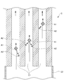
- FIG. 4 is a conceptual diagram showing a cross section of the vicinity of the denitration catalyst C fixed to the upstream fixing member 22.
- the denitration catalyst C As shown in FIG. 4, the denitration catalyst C according to the present embodiment is arranged and fixed so that the flow path directions of the plurality of through holes C1 are substantially perpendicular to the horizontal plane. Then, the abrasive A mixed with air flows through the plurality of through holes C1 from the lower side to the upper side through the upstream fixing member 22 connected below the denitration catalyst C, and the inner surface of the through holes C1. Is polished.
- the abrasive material A is composed of a first abrasive grain A1 and a second abrasive grain A2 (hereinafter, may be simply referred to as "abrasive grain A1" and “abrasive grain A2").
- the abrasive grains A1 and the abrasive grains A2 have different speeds of flowing through the through hole C1.
- the abrasive grains A1 and the abrasive grains A2 differ in at least one of the average particle diameter and the density. As shown in FIG.
- the abrasive grains A1 and the abrasive grains A2 are composed of, for example, abrasive grains A1 having a large particle size and abrasive grains A2 having a small particle size.
- the densities of the abrasive grains A1 and the abrasive grains A2 are the same, the abrasive grains A1 having a large particle size have a larger mass than the abrasive grains A2.
- the gravity acting on the abrasive grains A1 is larger than that of the abrasive grains A2, so that the flow speed of the abrasive grains A1 is increased. It becomes smaller than the distribution speed of A2.
- the abrasive grains A2 collide with the abrasive grains A1, and the abrasive grains A2 are scattered in the through hole C1.
- the proportion of abrasive grains A2 that collide with the inner surface of the through hole C1 increases, and as a result, the polishing efficiency of the denitration catalyst C improves.
- the polishing efficiency of the denitration catalyst C can be improved by using the two types of abrasive grains A1 and abrasive grains A2 having different distribution speeds as the polishing material A.
- the particle size defined in JIS R6001 is preferably F7 to F14, more preferably F8 to F12, and even more preferably F10.
- the average particle size of the abrasive grains A2 is preferably F36 to F60, more preferably F40 to F54, and even more preferably F46, as defined in JIS R6001.
- the average particle size, which is the particle size at the cumulative height of 50% of the abrasive grains A1, is preferably 1.65 to 2.16 mm.
- the average particle size, which is the particle size of the 50% cumulative height of the abrasive grains A2 is preferably 0.30 to 0.45 mm.
- the ratio of the abrasive grains A1 in the abrasive A is preferably 5 to 15% by weight. If the ratio of the abrasive grains A1 is too small with respect to the above range, the polishing efficiency cannot be sufficiently improved. Further, if the ratio of the abrasive grains A1 is too large with respect to the above range, the denitration catalyst C cannot be uniformly polished, and there will be a portion where the polishing is insufficient and a portion where the polishing is excessive. In addition, the denitration catalyst C may be damaged.
- the materials of the abrasive grains A1 and the abrasive grains A2 are not particularly limited, and are, for example, diamond, CBN (cubic boron nitride), B4C (boron carbide), silicon carbide, silica, ceria, alumina, white alumina, zirconia, and titania. , Manganese oxide, barium carbonate, chromium oxide, iron oxide and the like.
- the average particle diameters of the abrasive grains A1 and the abrasive grains A2 are different, so that the speed at which the through holes C1 of the abrasive grains A1 and the abrasive grains A2 flow can be increased. Can be different. Further, the materials of the abrasive grains A1 and the abrasive grains A2 may be different.
- the speed at which the through holes C1 of the abrasive grains A1 and the abrasive grains A2 flow can be made different depending on the density difference between the abrasive grains A1 and the abrasive grains A2.
- the abrasive grains having a low flow rate it is preferable that the hardness of the abrasive grains A1 is higher than the hardness of the abrasive grains A2 having a high flow rate.
- Abrasive grains A1 and abrasive grains A2 need to be replenished at regular intervals because cracks and chips occur as the use continues and the polishing efficiency decreases due to the removal of corners.
- the abrasive grains A1 are less likely to be worn, and the frequency of replenishment of the abrasive grains A1 can be reduced.
- alumina or white alumina is used as the abrasive grains A2
- diamond or CBN having a higher hardness is preferable to use diamond or CBN having a higher hardness as the abrasive grains A1.
- the denitration catalyst C whose denitration performance has deteriorated which is the object to be polished by the denitration catalyst polishing device 1, is removed from the denitration device 160 of the coal-fired power generation facility 100.
- the through hole C1 of the denitration catalyst C may be blocked by coal ash or the like, the blocked object is appropriately removed by air blowing, washing with water, or the like.
- the denitration catalyst C is sandwiched between the upstream fixing member 22 and the downstream fixing member 32 to fix the denitration catalyst C.
- the denitration catalyst C may be arranged and fixed so that the side with a large amount of deposits, which was the end on the inlet side of the exhaust gas in the denitration device 160, is on the downstream side where the flow velocity of the abrasive A is high. ..
- the abrasive A flows into the through hole C1 of the denitration catalyst C via the upstream side flow path 21 and the upstream side fixing member 22.
- the abrasive material A is composed of abrasive grains A1 and abrasive grains A2.
- the abrasive grains A1 have a larger average particle size than the abrasive grains A2, and the flow speed in the through hole C1 is lower than that of the abrasive grains A2.
- the abrasive grains A2 collide with the abrasive grains A1 and scatter, so that they easily collide with the inner surface of the through hole C1.
- the inner surface of the through hole C1 is efficiently polished by the abrasive grains A1 and the abrasive grains A2.
- the polishing material A flows out from the downstream fixing member 32 after polishing the inner surface of the through hole C1.
- the outflowing abrasive material A and the object to be polished are sucked together with air by the suction fan 70 and flow into the cyclone 40 through the downstream flow path 31.
- the abrasive material A and the object to be polished are separated, and the abrasive material A is supplied to the mixing unit 10 via the abrasive material supply path 33. That is, the abrasive A circulates in the denitration catalyst polishing apparatus 1.
- the object to be polished separated by the cyclone 40 is sucked by the suction fan 70, flows into the bag filter 60 through the transport pipe 41, and is collected.
- the air after the object to be polished is collected is discharged to the outside through the exhaust duct 71.
- the denitration catalyst C is regenerated by continuing the operation of the denitration catalyst polishing device 1 for a predetermined time, polishing the inner surface of the through hole C1 of the denitration catalyst C, and removing the deposits and the like adhering to the inner surface of the through hole C1.
- the method for polishing and regenerating the denitration catalyst C includes a step of replenishing the abrasive material A.
- the denitration catalyst C is polished for a predetermined time, the polishing material is cracked or chipped, and the corners of the polishing material are removed, so that the polishing efficiency is lowered.
- the abrasive grains having a particle size smaller than a certain level are separated by the cyclone 40 together with the object to be polished and flow into the bag filter 60 side. That is, the amount of the abrasive A circulating in the apparatus decreases with the polishing time. Therefore, in order to maintain the polishing efficiency, the abrasive material A is replenished by the replenishment step of the abrasive material A.
- the replenishment step can be performed, for example, at the timing when the denitration catalyst polishing device 1 is stopped and the denitration catalyst C is replaced.
- the polishing material A may be added to the mixing portion 10 of the denitration catalyst polishing apparatus 1 to replenish the polishing material A.
- the abrasive grain A1 having a large average particle size is replenished with the abrasive grain A2 having a small average particle size, with the ratio of the abrasive grain A1 in the abrasive material A being 5 to 20% by weight. ..
- the ratio of the abrasive grains A1 is higher than the ratio of the abrasive grains A1 in the abrasive material A before the start of polishing.
- the present invention is not limited to the above embodiment, and can be appropriately modified.
- the abrasive grains A1 and the abrasive grains A2 according to the above embodiment have been described as having different average particle diameters, but the present invention is not limited to the above.
- the abrasive grains A1 and the abrasive grains A2 may have different speeds of flowing through the through holes C1. For example, when the density of the abrasive grains A1 is larger than the density of the abrasive grains A2 and the sizes are the same, the mass of the abrasive grains A1 is larger than the mass of the abrasive grains A2.
- the flow speeds of the two types of abrasive grains are similarly different, and the same phenomenon occurs in which the abrasive grains A2 collide with the abrasive grains A1 and scatter, and the polishing efficiency can be improved.
- the average densities of the abrasive grains A1 and the abrasive grains A2 can be made different.
- the abrasive grains A1 and the abrasive grains A2 may have different distribution speeds because both the average particle size and the average density are different.
- the abrasive material A has been described as being composed of abrasive grains A1 and abrasive grains A2, but the present invention is not limited to the above.
- the abrasive material A may contain other abrasive grains in addition to the abrasive grains A1 and the abrasive grains A2.
- Denitration catalyst polishing device 10 Mixing part 20 Inflow path 22 Upstream side fixing member 70 Suction fan (suction part) C Denitration catalyst C1 Through hole A Abrasive A1 First abrasive grain A2 Second abrasive grain
Abstract
脱硝触媒の研磨効率を向上させることができる脱硝触媒研磨方法及び脱硝触媒研磨装置を提供すること。 長手方向に延びる複数の貫通孔C1が設けられた脱硝触媒Cの貫通孔C1に、空気と共に研磨材Aを流通させて、貫通孔C1の内面を研磨する脱硝触媒研磨方法。脱硝触媒Cは、貫通孔C1の流路方向が水平面に対して略垂直になるように配置され、研磨材Aは、貫通孔C1の下方から上方に向けて流通し、研磨材Aは、第1の砥粒A1と、第2の砥粒A2と、を含み、第1の砥粒A1と、第2の砥粒A2とは、貫通孔C1を流通する速度が異なるため、第1の砥粒A1に第2の砥粒A2が衝突して飛散し、効率よく貫通孔C1の内面を研磨できる。
Description
本発明は、脱硝触媒を研磨する、脱硝触媒研磨方法及び脱硝触媒研磨装置に関する。
火力発電所では、石炭燃焼に伴い窒素酸化物が発生する。環境保全のため、窒素酸化物の排出量は一定水準以下に抑える必要がある。このため、火力発電所には窒素酸化物を還元するための脱硝触媒が充てんされた脱硝装置が設置されている。脱硝触媒は、使用の継続に伴い性能が低下する。性能の低下した脱硝触媒を再生する技術の一つとして研磨再生が挙げられる。研磨再生は、性能の低下した脱硝触媒の表面を研磨することで、触媒性能を回復させる技術である。
特許文献1には、研磨材(研削材)と気体との混合物を脱硝触媒の貫通孔に通過させて、貫通孔の内壁を研削する脱硝触媒の再生方法に関する技術が開示されている。脱硝触媒からなる被研削部材の一端部には、当該被研削部材の断面積より大きな断面積の拡開部を具備する上流固定部材が連結される。当該拡開部には、スクリーン部材が配置される。このような拡開部内で、研磨材と気体との混合物は流速が低下されると共に分散され、貫通孔の内壁の均一な研削が可能となる。
特許文献1に記載された技術は、拡開部内で研磨材と気体との混合物の流速を低下させ、分散させることで貫通孔を均一に研磨できるものであるが、研磨材の流速を低下させれば研磨効率が低下する問題がある。しかし、研磨効率を向上させるため、研磨材の流速を上昇させるのみでは、必ずしも研磨効率の向上に繋がらない場合があった。
本発明は、上記に鑑みてなされたものであり、脱硝触媒の研磨効率を向上させることができる脱硝触媒研磨方法及び脱硝触媒研磨装置に関する。
本発明は、長手方向に延びる複数の貫通孔が設けられた脱硝触媒の前記貫通孔に、空気と共に研磨材を流通させて、前記貫通孔の内面を研磨する脱硝触媒研磨方法であって、前記脱硝触媒は、前記貫通孔の流路方向が水平面に対して略垂直になるように配置され、前記研磨材は、前記貫通孔の下方から上方に向けて流通し、前記研磨材は、第1の砥粒と、第2の砥粒と、を含み、前記第1の砥粒と、前記第2の砥粒とは、前記貫通孔を流通する速度が異なる、脱硝触媒研磨方法に関する。
前記第1の砥粒の平均粒子径D1は、前記第2の砥粒の平均粒子径D2よりも大きいことが好ましい。
前記平均粒子径D1は、1.65~2.16mmであり、前記平均粒子径D2は0.30~0.45mmであることが好ましい。
前記第1の砥粒は、前記研磨材中に5~15重量%含まれることが好ましい。
前記研磨材の補充工程を有し、前記研磨材の補充工程で補充される前記第1の砥粒は、補充される前記研磨材中に5~20重量%含まれることが好ましい。
また、本発明は、長手方向に延びる複数の貫通孔が設けられた脱硝触媒の前記貫通孔に、空気と共に研磨材を流通させて、前記貫通孔の内面を研磨する脱硝触媒研磨装置であって、前記脱硝触媒の上流側に配置され、研磨材と空気とを混合する混合部と、前記混合部と、前記脱硝触媒とを接続し、前記脱硝触媒の下方から空気と混合された前記研磨材が流入する流入路と、前記脱硝触媒を、前記貫通孔の流路方向が水平面に対して略垂直になるように固定する固定部材と、前記脱硝触媒の下流側に配置され、前記脱硝触媒の上方から空気と共に研磨材を吸引する吸引部と、を有し、前記研磨材は、第1の砥粒と、第2の砥粒と、を含み、前記第1の砥粒と、前記第2の砥粒とは、前記貫通孔を流通する速度が異なる、脱硝触媒研磨装置に関する。
本発明は、脱硝触媒の研磨効率を向上させることができる脱硝触媒研磨方法及び脱硝触媒研磨装置を提供できる。
以下、本発明の実施形態について説明する。
本発明の実施形態に係る脱硝触媒研磨方法及び脱硝触媒研磨装置の被研磨対象である脱硝触媒は、例えば、以下説明する石炭火力発電設備100で一定期間使用され、性能の低下した脱硝触媒Cである。
本発明の実施形態に係る脱硝触媒研磨方法及び脱硝触媒研磨装置の被研磨対象である脱硝触媒は、例えば、以下説明する石炭火力発電設備100で一定期間使用され、性能の低下した脱硝触媒Cである。
[石炭火力発電設備]
図1に示すように、石炭火力発電設備100は、石炭バンカ110と、給炭機115と、微粉炭機120と、微粉炭供給管130と、燃焼ボイラ140と、燃焼ボイラ140の下流側に設けられる排気通路150と、この排気通路150に設けられる脱硝装置160、空気予熱器170、熱回収用ガスヒータ180、電気集塵装置190、誘引通風機210、湿式脱硫装置220、再加熱用ガスヒータ230、脱硫通風機240、及び煙突250と、を備える。
図1に示すように、石炭火力発電設備100は、石炭バンカ110と、給炭機115と、微粉炭機120と、微粉炭供給管130と、燃焼ボイラ140と、燃焼ボイラ140の下流側に設けられる排気通路150と、この排気通路150に設けられる脱硝装置160、空気予熱器170、熱回収用ガスヒータ180、電気集塵装置190、誘引通風機210、湿式脱硫装置220、再加熱用ガスヒータ230、脱硫通風機240、及び煙突250と、を備える。
石炭バンカ110は、図示しない石炭サイロから運炭設備により供給される石炭を貯蔵する。給炭機115は、石炭バンカ110から供給される石炭を所定の供給スピードで微粉炭機120に供給する。
微粉炭機120は、給炭機115から供給された石炭を平均粒径60μm~80μmに粉砕して微粉炭を製造する。微粉炭機120としては、ローラミル、チューブミル、ボーラミル、ビータミル、インペラーミル等が用いられる。
微粉炭機120は、給炭機115から供給された石炭を平均粒径60μm~80μmに粉砕して微粉炭を製造する。微粉炭機120としては、ローラミル、チューブミル、ボーラミル、ビータミル、インペラーミル等が用いられる。
燃焼ボイラ140は、微粉炭供給管微粉炭機130から供給された微粉炭を、強制的に供給された空気と共に微粉炭バーナbにより燃焼する。微粉炭を燃焼することによりクリンカアッシュ及びフライアッシュなどの石炭灰が生成されると共に、排ガスが発生する。クリンカアッシュとは、石炭灰のうち、燃焼ボイラ140の底部に落下する塊状の石炭灰をいう。フライアッシュとは、石炭灰のうち、排ガスと共に排気通路150側に流通する、粒径の小さい(粒径200μm程度以下)の石炭灰をいう。
排気通路150は、燃焼ボイラ140の下流側に配置され、燃焼ボイラ140で発生した排ガス及び石炭灰を流通させる。
排気通路150は、燃焼ボイラ140の下流側に配置され、燃焼ボイラ140で発生した排ガス及び石炭灰を流通させる。
脱硝装置160は、排ガス中の窒素酸化物を除去する。脱硝装置160は、例えば、乾式アンモニア接触還元法により排ガス中の窒素酸化物を除去する。乾式アンモニア接触還元法は、比較的高温(300℃~400℃)の排ガス中に還元剤としてアンモニアガスを注入し、脱硝触媒との作用により排ガス中の窒素酸化物を窒素と水蒸気に分解する方法である。
脱硝装置160は、図2に示すように、脱硝反応が行われる脱硝反応器161と、脱硝反応器161の内部に配置される複数段の脱硝触媒層162とを備える。脱硝触媒層162は、複数のケーシング163により構成される。ケーシング163には、複数の脱硝触媒Cが収容される。
脱硝触媒Cは、長手方向に延びる複数の貫通孔C1が形成されたハニカム構造を有する、長尺状(直方体状)の触媒である。複数の脱硝触媒Cは、貫通孔C1の延びる方向が排ガスの流路に沿うように配置される。
脱硝触媒Cは、長手方向に延びる複数の貫通孔C1が形成されたハニカム構造を有する、長尺状(直方体状)の触媒である。複数の脱硝触媒Cは、貫通孔C1の延びる方向が排ガスの流路に沿うように配置される。
空気予熱器170は、排気通路150における脱硝装置160の下流側に配置される。空気予熱器170は、脱硝装置160を通過した排ガスと燃焼用空気とを熱交換させ、排ガスを冷却すると共に、燃焼用空気を加熱する。加熱された燃焼用空気は、押込通風機175によりボイラ140に供給される。
熱回収用ガスヒータ180は、排気通路150における空気予熱器170の下流側に配置される。熱回収用ガスヒータ180には、空気予熱器170において熱回収された排ガスが供給される。熱回収用ガスヒータ180は、排ガスから更に熱回収を行う。
電気集塵装置190は、排気通路150における熱回収用ガスヒータ180の下流側に配置される。電気集塵装置190には、熱回収用ガスヒータ180において熱回収された排ガスが供給される。電気集塵装置190は、電極に電圧を印加することによって排ガス中の石炭灰(フライアッシュ)を収集(捕捉)する装置である。電気集塵装置190において収集(捕捉)されるフライアッシュは、フライアッシュ回収装置191に回収される。
誘引通風機210は、排気通路150における電気集塵装置190の下流側に配置される。誘引通風機210は、電気集塵装置190においてフライアッシュが除去された排ガスを、一次側から取り込んで二次側に送り出す。
脱硫装置220は、排気通路150における誘引通風機210の下流側に配置される。脱硫装置220には、誘引通風機210から送り出された排ガスが供給される。脱硫装置220は、例えば湿式石灰-石膏法により排ガス中の硫黄酸化物を除去する。湿式石灰-石膏法は、排ガスに石灰石と水との混合液を吹き付けることにより、排ガスに含有されている硫黄酸化物を混合液に吸収させて脱硫石膏スラリーを生成させ、排ガス中の硫黄酸化物を除去する方法である。この際に発生したホウ素やセレン等の微量物質が含まれる排水は、排水処理装置221によって処理される。
再加熱用ガスヒータ230は、排気通路150における脱硫装置220の下流側に配置される。再加熱用ガスヒータ230には、脱硫装置220において硫黄酸化物が除去された排ガスが供給される。再加熱用ガスヒータ230は、排ガスを加熱する。熱回収用ガスヒータ180及び再加熱用ガスヒータ230は、排気通路150における、空気予熱器170と電気集塵装置190との間を流通する排ガスと、脱硫装置220と脱硫通風機240との間を流通する排ガスと、の間で熱交換を行うガス-ガスヒータとして構成してもよい。
脱硫通風機240は、排気通路150における再加熱用ガスヒータ230の下流側に配置される。脱硫通風機240は、再加熱用ガスヒータ230において加熱された排ガスを一次側から取り込んで二次側に送り出す。
煙突250は、排気通路150における脱硫通風機240の下流側に配置される。煙突250には、再加熱用ガスヒータ230で加熱された排ガスが導入される。煙突250は、排ガスを排出する。
[脱硝触媒研磨装置]
上記説明した石炭火力発電設備100に用いられる脱硝触媒Cは、使用の継続に伴いシンタリング等の熱的劣化、触媒成分の被毒による化学的劣化、及び煤塵が触媒表面を被覆する物理的劣化等により、脱硝性能が低下する。脱硝性能が低下した脱硝触媒Cは、触媒表面である貫通孔C1の内面を研磨し、表面の付着物等を除去することで脱硝性能が回復する。
以下、脱硝性能の低下した脱硝触媒Cの貫通孔C1の内面を研磨し、脱硝性能を回復させる脱硝触媒研磨装置1について説明する。
上記説明した石炭火力発電設備100に用いられる脱硝触媒Cは、使用の継続に伴いシンタリング等の熱的劣化、触媒成分の被毒による化学的劣化、及び煤塵が触媒表面を被覆する物理的劣化等により、脱硝性能が低下する。脱硝性能が低下した脱硝触媒Cは、触媒表面である貫通孔C1の内面を研磨し、表面の付着物等を除去することで脱硝性能が回復する。
以下、脱硝性能の低下した脱硝触媒Cの貫通孔C1の内面を研磨し、脱硝性能を回復させる脱硝触媒研磨装置1について説明する。
本実施形態に係る脱硝触媒研磨装置1は、脱硝触媒Cの貫通孔C1に空気と共に研磨材Aを流通させて、貫通孔C1の内面を研磨する装置である。脱硝触媒研磨装置1は、図3に示すように、混合部10と、流入路20と、流出路30と、サイクロン40と、コンプレッサ50と、バグフィルタ60と、吸引ファン70と、を備える。脱硝触媒研磨装置1の被研磨対象である脱硝触媒Cは、流入路20における上流側固定部材22と、流出路30における下流側固定部材32との間に挟持される。脱硝触媒Cは、脱硝触媒Cの貫通孔C1の流路方向が水平面に対して略垂直になるように固定される。
混合部10は、空気と研磨材Aとを混合し、流入路20を介して脱硝触媒Cに空気と混合された研磨材Aを供給する。混合部10には、ブラストガン11と、漏斗部12と、これらを収容するキャビネット13とが設けられる。ブラストガン11は、エアホース51を介してコンプレッサ50と連結されており、圧縮空気を噴射可能である。ブラストガン11は、複数台設けられていてもよい。ブラストガン11には、後述する研磨材供給路33が連結される。ブラストガン11から圧縮空気が噴射されると、エジェクター効果が生じ、研磨材供給路33を通じて研磨材Aがブラストガン11内に供給される。そして、ブラストガン11の内部で研磨材Aと圧縮空気とが混合され、漏斗部12に噴射される。噴射された研磨材Aは、空気と均一に混合された状態で、漏斗部12を通じて流入路20に流入する。
流入路20は、脱硝触媒Cの上流側の流路であり、空気と混合された研磨材Aが脱硝触媒Cの下方から流入する流路である。流入路20は、上流側流路21及び上流側固定部材22からなる。上流側流路21は、屈曲部を有する流路であり、上流側が漏斗部12と連結され、下流側が上流側固定部材22と連結される。上流側固定部材22は、直線状の流路を有し、下流側が脱硝触媒Cの下端部(上流側端部)と連結されて脱硝触媒Cを固定する。空気と混合された研磨材Aは、上流側固定部材22を通じて脱硝触媒Cの貫通孔C1に流入する。脱硝触媒Cの貫通孔C1に流入する研磨材Aの構成については、後段で詳述する。
流出路30は、脱硝触媒Cの下流側の流路である。流出路30は、研磨材Aと、脱硝触媒Cの表面が研磨されることで生じた被研磨物とが流通する流路である。研磨材Aと被研磨物とは、吸引部としての吸引ファン70により空気と共に吸引される。流出路30の途中にはサイクロン40が設けられ、研磨材Aと被研磨物とが分離される。
流出路30は、脱硝触媒Cの上端部(下流側端部)と連結されて脱硝触媒Cを固定する下流側固定部材32と、下流側固定部材32とサイクロン40とを連結する下流側流路31と、サイクロン40と混合部10とを連結する研磨材供給路33と、を有する。
流出路30は、脱硝触媒Cの上端部(下流側端部)と連結されて脱硝触媒Cを固定する下流側固定部材32と、下流側固定部材32とサイクロン40とを連結する下流側流路31と、サイクロン40と混合部10とを連結する研磨材供給路33と、を有する。
サイクロン40は、公知のサイクロン分級器であり、混合部10よりも高い位置に配置される。サイクロン40の上流端は、下流側流路31と連結される。サイクロン40の下部には研磨材供給路33が連結され、サイクロン40により分離された研磨材Aは、研磨材供給路33を通じて重力により落下して混合部10に供給される。サイクロン40の下流端は、搬送パイプ41と連結され、搬送パイプ41の下流端は、バグフィルタ60と連結される。サイクロン40により分離された被研磨物は、空気と共に搬送パイプ41を通じてバグフィルタ60に流入する。
バグフィルタ60は、公知の集塵装置である。バグフィルタ60は、脱硝触媒Cの被研磨物を含む空気中の粉塵を捕集する。捕集された粉塵は、バグフィルタ60の下部に設けられた図示しない貯蔵部に貯蔵され、所望のタイミングで回収される。バグフィルタ60の下流端は、連結パイプ61と連結される。連結パイプ61の下流端は、吸引部としての吸引ファン70に連結される。バグフィルタ60を通過して粉塵が除去された清浄な空気は、吸引ファン70によって吸引されて、排気ダクト71により大気中に排出される。
次に、本実施形態に係る脱硝触媒研磨装置1の、脱硝触媒Cに流入する研磨材Aの構成について、図面を参照して以下説明する。図4は、上流側固定部材22に固定された脱硝触媒C付近の断面を示す概念図である。
図4に示すように、本実施形態に係る脱硝触媒Cは、複数の貫通孔C1の流路方向が水平面に対して略垂直になるように配置されて固定される。そして、複数の貫通孔C1に対し、脱硝触媒Cの下方に連結される上流側固定部材22を通じ、空気と混合された研磨材Aが、下方から上方に向けて流通し、貫通孔C1の内面が研磨される。
本実施形態に係る研磨材Aは、第1の砥粒A1と、第2の砥粒A2(以下、単に「砥粒A1」及び「砥粒A2」と記載する場合がある)と、からなり、砥粒A1と砥粒A2とは、貫通孔C1を流通する速度が異なる。例えば、砥粒A1と砥粒A2とは、平均粒子径及び密度のうち、少なくとも何れかが異なる。
砥粒A1と、砥粒A2とは、図4に示すように、例えば粒径の大きな砥粒A1と、粒径の小さな砥粒A2と、からなる。砥粒A1と砥粒A2の密度が同じである場合、粒径の大きな砥粒A1は、砥粒A2と比較し、質量が大きい。従って、砥粒A1及び砥粒A2が空気と共に下方から上方に向けて貫通孔C1を流通する際、砥粒A1に働く重力が砥粒A2よりも大きいため、砥粒A1の流通速度は砥粒A2の流通速度よりも小さくなる。すると、砥粒A1に対し、砥粒A2が衝突し、砥粒A2は貫通孔C1の中で飛散する。これにより、貫通孔C1の内面に衝突する砥粒A2の割合が増える結果、脱硝触媒Cの研磨効率が向上する。
砥粒A1と、砥粒A2とは、図4に示すように、例えば粒径の大きな砥粒A1と、粒径の小さな砥粒A2と、からなる。砥粒A1と砥粒A2の密度が同じである場合、粒径の大きな砥粒A1は、砥粒A2と比較し、質量が大きい。従って、砥粒A1及び砥粒A2が空気と共に下方から上方に向けて貫通孔C1を流通する際、砥粒A1に働く重力が砥粒A2よりも大きいため、砥粒A1の流通速度は砥粒A2の流通速度よりも小さくなる。すると、砥粒A1に対し、砥粒A2が衝突し、砥粒A2は貫通孔C1の中で飛散する。これにより、貫通孔C1の内面に衝突する砥粒A2の割合が増える結果、脱硝触媒Cの研磨効率が向上する。
仮に、研磨材Aに含まれる砥粒の流通速度が同じである場合、上記のような衝突は起こりにくい。そうすると、研磨材Aの流速を増加させた場合に、貫通孔C1の内面に衝突せず、貫通孔C1をすり抜けてしまう砥粒の割合が増加する。従って、研磨材Aの流速を増加させても、それに見合う研磨効率の向上が得られない場合がある。本実施形態においては、2種類の流通速度が異なる砥粒A1及び砥粒A2を研磨材Aとして用いる事で、脱硝触媒Cの研磨効率を向上させることができる。
砥粒A1は、上記研磨効率を向上させるため、JIS R6001に規定される粒度がF7~F14であることが好ましく、粒度F8~F12であることがより好ましく、粒度F10であることが更に好ましい。同様に、砥粒A2の平均粒子径は、JIS R6001に規定される粒度がF36~F60であることが好ましく、粒度F40~F54であることがより好ましく、F46であることが更に好ましい。砥粒A1の累積高さ50%点の粒子径である平均粒子径は、1.65~2.16mmであることが好ましい。砥粒A2の累積高さ50%点の粒子径である平均粒子径は、0.30~0.45mmであることが好ましい。
砥粒A1の研磨材Aにおける割合は、5~15重量%であることが好ましい。砥粒A1の割合が上記範囲に対して少なすぎると、研磨効率を十分向上させることができない。また、砥粒A1の割合が上記範囲に対して多すぎると、脱硝触媒Cを均一に研磨できず、研磨が不十分な箇所と、研磨過剰な箇所が生じてしまう。また、脱硝触媒Cが破損する恐れがある。
砥粒A1及び砥粒A2の材質としては、特に制限されないが、例えば、ダイヤモンド、CBN(立方晶窒化ホウ素)、B4C(炭化ホウ素)、炭化ケイ素、シリカ、セリア、アルミナ、ホワイトアルミナ、ジルコニア、チタニア、マンガン酸化物、炭酸バリウム、酸化クロム、及び酸化鉄等が挙げられる。砥粒A1及び砥粒A2の材質を同一とする場合、砥粒A1及び砥粒A2の平均粒子径を異なるものとすることで、砥粒A1及び砥粒A2の貫通孔C1を流通する速度を異なるものにできる。
また、砥粒A1及び砥粒A2の材質を異なるものとしてもよい。この場合、平均粒子径以外に、砥粒A1と砥粒A2との密度差により、砥粒A1及び砥粒A2の貫通孔C1を流通する速度を異なるものにできる。更に、流通速度の小さい砥粒を砥粒A1とした場合に、砥粒A1の硬度を、流通速度が大きい砥粒A2の硬度よりも高いものとすることが好ましい。砥粒A1及び砥粒A2は、使用の継続に伴い、割れや欠けが生じ、また、角が取れることで研磨効率が低下するので、一定時間ごとに補充の必要がある。上記構成により、砥粒A1が摩耗しにくくなり、砥粒A1の補充頻度を低減することができる。例えば、砥粒A2としてアルミナやホワイトアルミナを用いる場合、砥粒A1として、より硬度の高いダイヤモンドやCBNを用いることが好ましい。
また、砥粒A1及び砥粒A2の材質を異なるものとしてもよい。この場合、平均粒子径以外に、砥粒A1と砥粒A2との密度差により、砥粒A1及び砥粒A2の貫通孔C1を流通する速度を異なるものにできる。更に、流通速度の小さい砥粒を砥粒A1とした場合に、砥粒A1の硬度を、流通速度が大きい砥粒A2の硬度よりも高いものとすることが好ましい。砥粒A1及び砥粒A2は、使用の継続に伴い、割れや欠けが生じ、また、角が取れることで研磨効率が低下するので、一定時間ごとに補充の必要がある。上記構成により、砥粒A1が摩耗しにくくなり、砥粒A1の補充頻度を低減することができる。例えば、砥粒A2としてアルミナやホワイトアルミナを用いる場合、砥粒A1として、より硬度の高いダイヤモンドやCBNを用いることが好ましい。
(研磨再生方法)
次に、脱硝触媒研磨装置1を用いて脱硝触媒Cを研磨再生する方法について説明する。
脱硝触媒研磨装置1の被研磨対象である、脱硝性能が低下した脱硝触媒Cを、石炭火力発電設備100の脱硝装置160から取り外す。この際、脱硝触媒Cの貫通孔C1は、石炭灰等で閉塞されている場合があるため、適宜エアブローや水洗等により閉塞物を取り除く。次に、上流側固定部材22と、下流側固定部材32との間に脱硝触媒Cを挟持し、脱硝触媒Cを固定する。この際、例えば脱硝触媒Cの、脱硝装置160における排ガスの入口側端部であった付着物の多い側を、研磨材Aの流速の高い下流側となるように配置して固定してもよい。
次に、脱硝触媒研磨装置1を用いて脱硝触媒Cを研磨再生する方法について説明する。
脱硝触媒研磨装置1の被研磨対象である、脱硝性能が低下した脱硝触媒Cを、石炭火力発電設備100の脱硝装置160から取り外す。この際、脱硝触媒Cの貫通孔C1は、石炭灰等で閉塞されている場合があるため、適宜エアブローや水洗等により閉塞物を取り除く。次に、上流側固定部材22と、下流側固定部材32との間に脱硝触媒Cを挟持し、脱硝触媒Cを固定する。この際、例えば脱硝触媒Cの、脱硝装置160における排ガスの入口側端部であった付着物の多い側を、研磨材Aの流速の高い下流側となるように配置して固定してもよい。
脱硝触媒研磨装置1の作動を開始すると、吸引ファン70及びコンプレッサ50が作動を開始し、混合部10で空気と混合された研磨材Aが上流側に吸引される。研磨材Aは、上流側流路21及び上流側固定部材22を介して脱硝触媒Cの貫通孔C1に流入する。研磨材Aは、砥粒A1及び砥粒A2からなり、例えば砥粒A1は砥粒A2よりも平均粒子径が大きく、貫通孔C1における流通速度が砥粒A2よりも小さい。従って、砥粒A2は砥粒A1と衝突して飛散することで、貫通孔C1の内面に衝突しやすい。このような砥粒A1及び砥粒A2により、効率よく貫通孔C1の内面が研磨される。
研磨材Aは、貫通孔C1の内面の研磨を行った後、下流側固定部材32から流出する。流出した研磨材Aと被研磨物とは、空気と共に吸引ファン70により吸引されて、下流側流路31を介してサイクロン40に流入する。サイクロン40では、研磨材Aと被研磨物とが分離され、研磨材Aは研磨材供給路33を介して混合部10に供給される。即ち、研磨材Aは脱硝触媒研磨装置1内を循環する。サイクロン40で分離された被研磨物は吸引ファン70により吸引されて、搬送パイプ41を介してバグフィルタ60に流入して捕集される。被研磨物が捕集された後の空気は排気ダクト71を通じて外部に排出される。所定時間、脱硝触媒研磨装置1の作動を継続させ、脱硝触媒Cの貫通孔C1の内面を研磨し、貫通孔C1の内面に付着した付着物等を取り除くことで脱硝触媒Cを再生する。
本実施形態に係る脱硝触媒Cの研磨再生方法は、研磨材Aの補充工程を含む。所定時間、脱硝触媒Cの研磨を行うと、研磨材に割れや欠けが生じ、また、研磨材の角が取れることで研磨効率が低下する。また、粒子径が一定以上小さくなった砥粒は、被研磨物と共にサイクロン40で分離されてバグフィルタ60側に流入する。つまり、装置内を循環する研磨材Aの量は研磨時間と共に減少する。従って、研磨効率を維持するため、研磨材Aの補充工程により、研磨材Aの補充を行う。上記補充工程は、例えば脱硝触媒研磨装置1を停止させ、脱硝触媒Cを取り換えるタイミングで行うことができる。あるいは、脱硝触媒Cの研磨中に、脱硝触媒研磨装置1の混合部10に研磨材Aを投入して補充してもよい。
研磨材Aの補充工程では、例えば平均粒子径の大きな砥粒A1の、研磨材Aにおける割合を5~20重量%とし、残りを平均粒子径の小さな砥粒A2とした研磨材Aを補充する。上記砥粒A1の割合は、研磨開始前の研磨材Aにおける砥粒A1の割合よりも高い。これは、砥粒A1は、砥粒A2と衝突して割れが生じる等の理由により、流通速度の小さい砥粒A1として機能しなくなる割合が砥粒A2よりも高いためである。
本発明は、上記実施形態に制限されるものではなく、適宜変更が可能である。
上記実施形態に係る砥粒A1及び砥粒A2を、平均粒子径が異なるものとして説明したが、上記に限定されない。砥粒A1及び砥粒A2は、貫通孔C1を流通する速度が異なるものであればよい。例えば、砥粒A1の密度が砥粒A2の密度よりも大きく、大きさが同じである場合、砥粒A1の質量は砥粒A2の質量と比較して大きくなる。これにより、同様に2種類の砥粒の流通速度に差が生じて砥粒A1に砥粒A2が衝突して飛散する同様の現象が起こり、研磨効率を向上させることができる。例えば砥粒A1と砥粒A2の材質を異なるものとすることで、砥粒A1と砥粒A2の平均密度を異なるものとすることができる。砥粒A1と砥粒A2とは、平均粒子径と平均密度のいずれもが異なることで、流通速度に差があるものであってもよい。
上記実施形態では、研磨材Aを砥粒A1及び砥粒A2からなるものとして説明したが、上記に限定されない。研磨材Aは、砥粒A1及び砥粒A2以外に、他の砥粒を含んでいてもよい。
1 脱硝触媒研磨装置
10 混合部
20 流入路
22 上流側固定部材
70 吸引ファン(吸引部)
C 脱硝触媒
C1 貫通孔
A 研磨材
A1 第1の砥粒
A2 第2の砥粒
10 混合部
20 流入路
22 上流側固定部材
70 吸引ファン(吸引部)
C 脱硝触媒
C1 貫通孔
A 研磨材
A1 第1の砥粒
A2 第2の砥粒
Claims (9)
- 長手方向に延びる複数の貫通孔が設けられた脱硝触媒の前記貫通孔に、空気と共に研磨材を流通させて、前記貫通孔の内面を研磨する脱硝触媒研磨方法であって、
前記脱硝触媒は、前記貫通孔の流路方向が水平面に対して略垂直になるように配置され、
前記研磨材は、前記貫通孔の下方から上方に向けて流通し、
前記研磨材は、第1の砥粒と、第2の砥粒と、を含み、
前記第1の砥粒と、前記第2の砥粒とは、前記貫通孔を流通する速度が異なる、脱硝触媒研磨方法。 - 前記第1の砥粒の平均粒子径D1は、前記第2の砥粒の平均粒子径D2よりも大きい、請求項1に記載の脱硝触媒研磨方法。
- 前記平均粒子径D1は、1.65~2.16mmであり、前記平均粒子径D2は0.30~0.45mmである、請求項2に記載の脱硝触媒研磨方法。
- 前記第1の砥粒は、前記研磨材中に5~15重量%含まれる、請求項1~3いずれかに記載の脱硝触媒研磨方法。
- 前記研磨材の補充工程を有し、
前記研磨材の補充工程で補充される前記第1の砥粒は、補充される前記研磨材中に5~20重量%含まれる、請求項1~4いずれかに記載の脱硝触媒研磨方法。 - 長手方向に延びる複数の貫通孔が設けられた脱硝触媒の前記貫通孔に、空気と共に研磨材を流通させて、前記貫通孔の内面を研磨する脱硝触媒研磨装置であって、
前記脱硝触媒の上流側に配置され、研磨材と空気とを混合する混合部と、
前記混合部と、前記脱硝触媒とを接続し、前記脱硝触媒の下方から空気と混合された前記研磨材が流入する流入路と、
前記脱硝触媒を、前記貫通孔の流路方向が水平面に対して略垂直になるように固定する固定部材と、
前記脱硝触媒の下流側に配置され、前記脱硝触媒の上方から空気と共に研磨材を吸引する吸引部と、を有し、
前記研磨材は、第1の砥粒と、第2の砥粒と、を含み、
前記第1の砥粒と、前記第2の砥粒とは、前記貫通孔を流通する速度が異なる、脱硝触媒研磨装置。 - 前記第1の砥粒の平均粒子径D1は、前記第2の砥粒の平均粒子径D2よりも大きい、請求項6に記載の脱硝触媒研磨装置。
- 前記平均粒子径D1は、1.65~2.16mmであり、前記平均粒子径D2は0.30~0.45mmである、請求項7に記載の脱硝触媒研磨装置。
- 前記第1の砥粒は、前記研磨材中に5~15重量%重量%含まれる、請求項6~8いずれかに記載の脱硝触媒研磨装置。
Priority Applications (2)
| Application Number | Priority Date | Filing Date | Title |
|---|---|---|---|
| JP2020535145A JP7464523B2 (ja) | 2020-02-28 | 2020-02-28 | 脱硝触媒研磨方法及び脱硝触媒研磨装置 |
| PCT/JP2020/008547 WO2021171627A1 (ja) | 2020-02-28 | 2020-02-28 | 脱硝触媒研磨方法及び脱硝触媒研磨装置 |
Applications Claiming Priority (1)
| Application Number | Priority Date | Filing Date | Title |
|---|---|---|---|
| PCT/JP2020/008547 WO2021171627A1 (ja) | 2020-02-28 | 2020-02-28 | 脱硝触媒研磨方法及び脱硝触媒研磨装置 |
Publications (1)
| Publication Number | Publication Date |
|---|---|
| WO2021171627A1 true WO2021171627A1 (ja) | 2021-09-02 |
Family
ID=77490898
Family Applications (1)
| Application Number | Title | Priority Date | Filing Date |
|---|---|---|---|
| PCT/JP2020/008547 WO2021171627A1 (ja) | 2020-02-28 | 2020-02-28 | 脱硝触媒研磨方法及び脱硝触媒研磨装置 |
Country Status (2)
| Country | Link |
|---|---|
| JP (1) | JP7464523B2 (ja) |
| WO (1) | WO2021171627A1 (ja) |
Citations (5)
| Publication number | Priority date | Publication date | Assignee | Title |
|---|---|---|---|---|
| JPS58150439A (ja) * | 1982-03-04 | 1983-09-07 | Mitsubishi Heavy Ind Ltd | 触媒の賦活方法 |
| JPS6257864A (ja) * | 1985-09-09 | 1987-03-13 | Ebara Corp | 曲り管部の研磨方法 |
| JPH04197451A (ja) * | 1990-11-29 | 1992-07-17 | Japan Carlit Co Ltd:The | 脱硝触媒の再生方法 |
| JP2012000693A (ja) * | 2010-06-14 | 2012-01-05 | Hidaka Fine-Technologies Co Ltd | 研削加工装置及び研削加工方法 |
| US20180141034A1 (en) * | 2015-05-12 | 2018-05-24 | Geesco Co., Ltd. | Method for regenerating catalyst |
-
2020
- 2020-02-28 WO PCT/JP2020/008547 patent/WO2021171627A1/ja active Application Filing
- 2020-02-28 JP JP2020535145A patent/JP7464523B2/ja active Active
Patent Citations (5)
| Publication number | Priority date | Publication date | Assignee | Title |
|---|---|---|---|---|
| JPS58150439A (ja) * | 1982-03-04 | 1983-09-07 | Mitsubishi Heavy Ind Ltd | 触媒の賦活方法 |
| JPS6257864A (ja) * | 1985-09-09 | 1987-03-13 | Ebara Corp | 曲り管部の研磨方法 |
| JPH04197451A (ja) * | 1990-11-29 | 1992-07-17 | Japan Carlit Co Ltd:The | 脱硝触媒の再生方法 |
| JP2012000693A (ja) * | 2010-06-14 | 2012-01-05 | Hidaka Fine-Technologies Co Ltd | 研削加工装置及び研削加工方法 |
| US20180141034A1 (en) * | 2015-05-12 | 2018-05-24 | Geesco Co., Ltd. | Method for regenerating catalyst |
Also Published As
| Publication number | Publication date |
|---|---|
| JPWO2021171627A1 (ja) | 2021-09-02 |
| JP7464523B2 (ja) | 2024-04-09 |
Similar Documents
| Publication | Publication Date | Title |
|---|---|---|
| US9643117B2 (en) | Dust separator useful with dry scrubber system | |
| JP6978345B2 (ja) | 脱硝触媒研磨装置及び脱硝触媒研磨方法 | |
| EP2878889B1 (en) | Dry scrubber system with air preheater protection | |
| EP2695659B1 (en) | High performance mercury capture | |
| JP3621822B2 (ja) | 排煙処理方法及び設備 | |
| WO2021171628A1 (ja) | 脱硝触媒研磨装置 | |
| JP5171184B2 (ja) | 石炭火力発電システム及びフライアッシュの平均粒径を拡大させる方法 | |
| WO2021171627A1 (ja) | 脱硝触媒研磨方法及び脱硝触媒研磨装置 | |
| JP7002964B2 (ja) | 脱硝触媒の研磨時間決定方法及び脱硝触媒の再生方法 | |
| WO2021245841A1 (ja) | 脱硝触媒研磨装置 | |
| WO2021171625A1 (ja) | 脱硝触媒研磨装置 | |
| WO2021245842A1 (ja) | 脱硝触媒研磨装置 | |
| WO2021171624A1 (ja) | 脱硝触媒研磨装置 | |
| US8398744B2 (en) | Method and apparatus for air pollution control | |
| WO2021171626A1 (ja) | 脱硝触媒研磨方法及び脱硝触媒研磨装置 | |
| WO2021171629A1 (ja) | 脱硝触媒研磨装置 | |
| JP6848598B2 (ja) | 脱硝触媒の再利用方法 | |
| JP6586032B2 (ja) | 排ガス処理方法および装置 | |
| WO2017022519A1 (ja) | 石炭火力発電設備 | |
| JP6836168B2 (ja) | 脱硝装置 | |
| US9084964B1 (en) | Radial fabric filter for particulate collection | |
| JPH0376963B2 (ja) | ||
| JPH05309229A (ja) | 半乾式及び乾式脱硫装置 | |
| JP3839450B2 (ja) | 排ガス処理装置 | |
| JP2008264662A (ja) | 排ガス処理方法及び排ガス処理装置 |
Legal Events
| Date | Code | Title | Description |
|---|---|---|---|
| ENP | Entry into the national phase |
Ref document number: 2020535145 Country of ref document: JP Kind code of ref document: A |
|
| 121 | Ep: the epo has been informed by wipo that ep was designated in this application |
Ref document number: 20921419 Country of ref document: EP Kind code of ref document: A1 |
|
| NENP | Non-entry into the national phase |
Ref country code: DE |
|
| 122 | Ep: pct application non-entry in european phase |
Ref document number: 20921419 Country of ref document: EP Kind code of ref document: A1 |