WO2021167005A1 - マスクデータ生成方法、およびマスクデータ生成プログラム - Google Patents
マスクデータ生成方法、およびマスクデータ生成プログラム Download PDFInfo
- Publication number
- WO2021167005A1 WO2021167005A1 PCT/JP2021/006127 JP2021006127W WO2021167005A1 WO 2021167005 A1 WO2021167005 A1 WO 2021167005A1 JP 2021006127 W JP2021006127 W JP 2021006127W WO 2021167005 A1 WO2021167005 A1 WO 2021167005A1
- Authority
- WO
- WIPO (PCT)
- Prior art keywords
- mask data
- value
- evaluation value
- data generation
- mask
- Prior art date
- Legal status (The legal status is an assumption and is not a legal conclusion. Google has not performed a legal analysis and makes no representation as to the accuracy of the status listed.)
- Ceased
Links
Images


Classifications
-
- G—PHYSICS
- G03—PHOTOGRAPHY; CINEMATOGRAPHY; ANALOGOUS TECHNIQUES USING WAVES OTHER THAN OPTICAL WAVES; ELECTROGRAPHY; HOLOGRAPHY
- G03F—PHOTOMECHANICAL PRODUCTION OF TEXTURED OR PATTERNED SURFACES, e.g. FOR PRINTING, FOR PROCESSING OF SEMICONDUCTOR DEVICES; MATERIALS THEREFOR; ORIGINALS THEREFOR; APPARATUS SPECIALLY ADAPTED THEREFOR
- G03F1/00—Originals for photomechanical production of textured or patterned surfaces, e.g., masks, photo-masks, reticles; Mask blanks or pellicles therefor; Containers specially adapted therefor; Preparation thereof
- G03F1/68—Preparation processes not covered by groups G03F1/20 - G03F1/50
- G03F1/70—Adapting basic layout or design of masks to lithographic process requirements, e.g., second iteration correction of mask patterns for imaging
-
- G—PHYSICS
- G03—PHOTOGRAPHY; CINEMATOGRAPHY; ANALOGOUS TECHNIQUES USING WAVES OTHER THAN OPTICAL WAVES; ELECTROGRAPHY; HOLOGRAPHY
- G03F—PHOTOMECHANICAL PRODUCTION OF TEXTURED OR PATTERNED SURFACES, e.g. FOR PRINTING, FOR PROCESSING OF SEMICONDUCTOR DEVICES; MATERIALS THEREFOR; ORIGINALS THEREFOR; APPARATUS SPECIALLY ADAPTED THEREFOR
- G03F7/00—Photomechanical, e.g. photolithographic, production of textured or patterned surfaces, e.g. printing surfaces; Materials therefor, e.g. comprising photoresists; Apparatus specially adapted therefor
- G03F7/70—Microphotolithographic exposure; Apparatus therefor
- G03F7/70216—Mask projection systems
- G03F7/70283—Mask effects on the imaging process
- G03F7/70291—Addressable masks, e.g. spatial light modulators [SLMs], digital micro-mirror devices [DMDs] or liquid crystal display [LCD] patterning devices
-
- G—PHYSICS
- G03—PHOTOGRAPHY; CINEMATOGRAPHY; ANALOGOUS TECHNIQUES USING WAVES OTHER THAN OPTICAL WAVES; ELECTROGRAPHY; HOLOGRAPHY
- G03F—PHOTOMECHANICAL PRODUCTION OF TEXTURED OR PATTERNED SURFACES, e.g. FOR PRINTING, FOR PROCESSING OF SEMICONDUCTOR DEVICES; MATERIALS THEREFOR; ORIGINALS THEREFOR; APPARATUS SPECIALLY ADAPTED THEREFOR
- G03F7/00—Photomechanical, e.g. photolithographic, production of textured or patterned surfaces, e.g. printing surfaces; Materials therefor, e.g. comprising photoresists; Apparatus specially adapted therefor
- G03F7/70—Microphotolithographic exposure; Apparatus therefor
- G03F7/70483—Information management; Active and passive control; Testing; Wafer monitoring, e.g. pattern monitoring
- G03F7/70491—Information management, e.g. software; Active and passive control, e.g. details of controlling exposure processes or exposure tool monitoring processes
- G03F7/70508—Data handling in all parts of the microlithographic apparatus, e.g. handling pattern data for addressable masks or data transfer to or from different components within the exposure apparatus
-
- G—PHYSICS
- G06—COMPUTING OR CALCULATING; COUNTING
- G06F—ELECTRIC DIGITAL DATA PROCESSING
- G06F30/00—Computer-aided design [CAD]
- G06F30/30—Circuit design
- G06F30/39—Circuit design at the physical level
- G06F30/398—Design verification or optimisation, e.g. using design rule check [DRC], layout versus schematics [LVS] or finite element methods [FEM]
Definitions
- the present invention relates to a mask data generation method and a mask data generation program.
- Non-Patent Document 1 a method for creating a pixel pattern in such a pixel-based mask.
- a first value or a second value different from the first value is set for each of a plurality of unit elements constituting the two-dimensional grid.
- the first evaluation value of the projected image based on the first mask data is calculated, and among the plurality of the unit elements included in the first mask data, the value of the first unit element in which the first value is set is set.
- the value of the second unit element, which is changed to the second value is arranged close to the first unit element on the two-dimensional grid, and the second value is set, is set to the first value.
- the second mask data is changed to generate the second mask data, the second evaluation value of the projected image based on the second mask data is calculated, the first evaluation value and the second evaluation value are compared, and based on the comparison result. Therefore, either the first mask data or the second mask data is selected as the output mask data.
- the mask data generation program differs from the first value or the first value for each of the plurality of unit elements constituting the two-dimensional grid for the data processing device including the computer.
- the first mask data in which the second value is set is stored in the storage area, the first evaluation value of the projected image based on the input mask data is calculated, and the plurality of the unit elements included in the input mask data are calculated.
- the value of the first unit element in which the first value is set is changed to the second value, and the second value is arranged in close proximity to the first unit element on the two-dimensional grid.
- the value of the second unit element in which the value is set is changed to the first value to generate the second mask data, the second evaluation value of the projected image based on the second mask data is calculated, and the second evaluation value is calculated. 1
- the evaluation value and the second evaluation value are compared, and either one of the first mask data or the second mask data is selected as output mask data based on the result of the comparison.
- FIG. 3A is a diagram showing an example of first mask data which is pixel-based mask data.
- FIG. 3B is a diagram showing an example of polygonal mask data in which the pattern is composed of polygons.
- FIG. 4A is an enlarged view of a part of the first mask data shown in FIG. 3A.
- FIG. 4B is a diagram showing the intensity distribution of the portion corresponding to the line segment A in FIG. 4A in the projection image calculated using the first mask data shown in FIG. 4A.
- FIG. 3A is a diagram showing an example of first mask data which is pixel-based mask data.
- FIG. 3B is a diagram showing an example of polygonal mask data in which the pattern is composed of polygons.
- FIG. 4A is an enlarged view of a part of the first mask data shown in FIG. 3A.
- FIG. 4B is a diagram showing the intensity distribution of the portion corresponding to the line segment A in FIG. 4A in the projection image calculated using the first mask data shown in FIG. 4
- FIG. 5A is a diagram showing the second mask data obtained by modifying a part of the first mask data shown in FIG. 4A.
- FIG. 5B is a diagram showing the intensity distribution of the portion corresponding to the line segment A in FIG. 5A in the projection image calculated using the second mask data shown in FIG. 5A.
- FIG. 1 is a diagram showing a flowchart showing a processing process of the mask data generation method of the first embodiment.
- the mask data is generated by causing the CPU 72 mounted on the computer 71 of the data processing device 70 to execute the mask data generation program stored in the data processing device 70 shown in FIG. Generate.
- the mask data generation program (hereinafter, also simply referred to as “program”) is stored in the memory 73 or the hard disk (HD) 77 of the computer 71.
- step S101 the CPU 72 controls the interface (I / F) and the like according to the program to load the first mask data, which will be described later, which is pixel-based mask data, into the memory 73 or HD77.
- the first mask data may be read from, for example, the optical drive (OD) 76 included in the computer 71, or may be downloaded from the server 79 or a server on a communication line (not shown) via the network line NW.
- the CPU 72 controls each part of the computer 71 according to the program, but in the following description of each step, the reference to the CPU 72, which is the execution subject, is omitted.
- FIG. 3A is a diagram showing an example of the first mask data 20.
- the first mask data 20 is two-dimensional array data (two-dimensional grid), and as an example, the addresses of the array variables are represented by X addresses (X1 to XN) and Y addresses (Y1 to YM). Therefore, the pixel P, which is the unit element of the first mask data 20, is specified as P (Xj, Yk) on the two-dimensional grid.
- the domain of the subscript j is a natural number of 0 or more and a natural number N or less
- the domain of the subscript k is a natural number of 0 or more and a natural number M or less.
- the X address corresponds to the position in the X direction on the mask when the first mask data 20 is formed on the mask (not shown), and the Y address is the position in the Y direction orthogonal to the X direction on the mask.
- the value of each pixel P of the first mask data 20 is, for example, either +1 or -1. These values correspond to the values of the amplitude transmittance or the amplitude reflectance of light in the mask formed by using the first mask data 20.
- pixels with a value of +1 are referred to as positive pixels PP, and pixels with a value of -1 (dots in FIG. 3A) are dotted.
- Pixel P) is called negative pixel MP.
- the value for the negative pixel MP is -1 times the value for the positive pixel PP.
- the above-mentioned +1 value can be called the first value, and the positive pixel PP whose value is set to +1 can also be called the first unit element.
- the above-mentioned value of -1 can be referred to as a second value, and the negative pixel MP whose value is set to -1 can also be referred to as a second unit element.
- FIG. 3B is a diagram showing an example of polygonal mask data 10 in which the pattern is composed of polygons for comparison.
- the polygonal mask data 10 is data corresponding to the transmittance distribution of the mask as an example, and includes light-shielding regions 11a to 11d having a low transmittance in the transmission region 12 having a high transmittance of about 1 (100%). It is data.
- the light-shielding areas 11a to 11d are also simply referred to as the light-shielding areas 11 together or alone.
- dimming regions 21a to 21d the portions corresponding to the light-shielding regions 11a to 11d of the polygonal mask data 10 of FIG. 3B are surrounded by broken lines as dimming regions 21a to 21d. Is shown. The dimming regions 21a to 21d, together or alone, are also simply referred to as dimming regions 21.
- the projected image obtained by loading the mask manufactured based on the first mask data 20 into the projection exposure apparatus is between the light transmitted through the plurality of pixels P arranged in and around the dimming region 21. Due to the interference of the above, the light intensity of the portion corresponding to the dimming region 21 is reduced. Therefore, when the mask based on the first mask data 20 shown in FIG. 3A is used, a projection image substantially similar to the case of using the mask based on the polygonal mask data 10 shown in FIG. 3B is obtained. Obtainable.
- the arrangement of the positive pixel PP and the negative pixel MP of the first mask data 20 is improved, and the region corresponding to the dimmed region 21 of the projected image is more preferably dimmed. There is a need. Therefore, by executing the following steps, the arrangement of the positive pixel PP and the negative pixel MP is corrected.
- step S102 first, a projection image obtained when the CPU 72 loads the mask manufactured based on the first mask data 20 into the projection exposure apparatus (hereinafter, also simply referred to as “projection image of the first mask data 20”). Calculate the intensity distribution of). Since the method of calculating the intensity distribution of the projected image is a well-known method, the description thereof will be omitted here. The intensity distribution is calculated using optical conditions such as the exposure wavelength, numerical aperture, illumination condition, and residual aberration of the projection exposure apparatus in which the mask manufactured based on the first mask data 20 is used.
- the scale of the light intensity (intensity distribution) is set so that the light intensity of the projected image corresponding to the portion where the positive pixel PP or the negative pixel MP is continuously distributed over a plurality of areas becomes a predetermined value (for example, 1). Set.
- FIG. 4A is an enlarged view showing a region 22 which is a part of the first mask data 20 shown in FIG. 3A
- FIG. 4B is a calculated first mask data 20. It is a figure which shows the intensity distribution IC1 in the part corresponding to the line segment A in FIG. 4A.
- the vertical axis I of the graph shown in FIG. 4B shows the light intensity of the projected image.
- FIG. 4B shows a projection image obtained when a mask manufactured based on the polygonal mask data 10 shown in FIG. 3B is loaded into the projection exposure apparatus (hereinafter, simply “polygon mask”.
- the intensity distribution IR at the portion corresponding to the line segment A in FIG. 4 (a) in (also referred to as “projected image of data 10”) is also shown.
- the intensity distribution IR of the projected image of the polygonal mask data 10 is also referred to as “intensity distribution IR of the reference image”.
- the intensity distribution IR of the reference image is calculated in advance before executing step S102. Since the method of calculating the intensity distribution IR of the reference image is also well known, the description thereof is omitted here.
- the intensity distribution IR of the reference image is also calculated using optical conditions such as the exposure wavelength, numerical aperture, illumination conditions, and residual aberration of the projection exposure apparatus in which the mask based on the polygonal mask data 10 is used. Further, the scale of the light intensity (intensity distribution) is set so that the light intensity of the projected image corresponding to the 12 portions of the large area transmission region becomes the above-mentioned predetermined value.
- the intensity distribution IC1 of the projected image of the first mask data 20 is slightly different from the intensity distribution IR of the reference image. It will be the one that was done.
- the amount of this deviation is quantified, the first evaluation value is calculated, and the parameter is used as a parameter for estimating the degree of optimization of the arrangement of the positive pixel PP and the negative pixel MP in the first mask data 20.
- the sum of squares of the difference D1 between the intensity distribution IC1 of the projected image of the first mask data 20 and the intensity distribution IR of the reference image is used as the first evaluation value. That is, at each point (X, Y) of the X coordinate and the Y coordinate where the projected image of the first mask data 20 is calculated, the intensity distribution IC1 of the projected image of the first mask data 20 and the intensity distribution IR of the reference image The square of the difference D1 is obtained, and the value obtained by integrating this over a predetermined range of the X coordinate and the Y coordinate is used.
- the first evaluation value is the sum of squares of the difference D1 and the first mask shown in FIG. 3 (a). It is calculated by integrating in the range of the X coordinate and the Y coordinate corresponding to the entire area of the X address and the Y address of the data 20.
- the first evaluation value is not limited to the sum of squares of the difference D1 between the intensity distribution IC1 of the projected image of the first mask data 20 and the intensity distribution IR of the reference image.
- the sum of squares of the differences from the value itself of the polygonal mask data 10 shown in FIG. 3B may be used.
- step S103 and subsequent steps the arrangement of the positive pixel PP and the negative pixel MP is improved.
- step S103 the loop of Yk, which is the Y address of the attention range 23, is started. In this loop, the Y address Yk changes in order from 1 to M.
- step S104 a loop of the value of Xj, which is the X address of the attention range 23, is started. In this loop, the X address, Xj, changes in order from 1 to N.
- step S105 the CPU 72 mixes positive pixel PP and negative pixel MP in the pixels P (Xj, Yk) specified by the addresses Xj and Yk on the two-dimensional grid of the first mask data 20 and the nearby pixels P. Decide whether to do it or not.
- the range of the vicinity in this determination is the range shown by the thick line frame as the attention range 23 in FIG. 4A, and is, for example, P (Xj, Yk), P (Xj, Yk + 1), P (Xj + 1, Yk).
- P (Xj + 1, Yk + 1) which is a range including a total of four pixels P in 2 rows and 2 columns.
- step S106 If the positive pixel PP and the negative pixel MP are mixed in the attention range 23, the process proceeds to step S106. On the other hand, if they are not mixed, that is, if the pixels P in the attention range 23 are all positive pixels PP or all negative pixels MP, the process proceeds to step S111.
- step S105 only when the values of P (Xj, Yk) and P (Xj + 1, Yk + 1) are equal and the values of P (Xj, Yk + 1) and P (Xj + 1, Yk) are equal. , It may be determined that positive pixel PP and negative pixel MP are mixed.
- step S106 the value of the positive pixel PP included in the attention range 23 of the first mask data 20 is changed to -1 to be a negative pixel MP, and the value of the negative pixel MP is changed to +1 to be a positive pixel PP.
- the second mask data is generated. That is, the arrangement of the positive pixel PP and the negative pixel MP in the attention range 23 is exchanged to generate the second mask data.
- FIG. 5A is a diagram showing a part of the generated second mask data 25, and of the second mask data 25, a region 22 which is a part of the first mask data 20 shown in FIG. 4A. The part corresponding to is shown.
- the arrangement of the positive pixel PP and the negative pixel MP in the attention range 23 is replaced with the arrangement in the first mask data 20.
- the CPU 72 is a projection image obtained when the mask manufactured based on the second mask data 25 is loaded into the projection exposure apparatus (hereinafter, also simply referred to as “projection image of the second mask data 25”). Calculate the intensity distribution of.
- the method of calculating the intensity distribution of the projected image is the same as the method of calculating the projected image of the first mask data 20 described above.
- 5 (b) shows the intensity distribution IC2 and the intensity distribution IC2 in the portion corresponding to the line segment A in FIG. 5 (a) in the calculated projection image of the second mask data 25, similarly to FIG. 4 (b). It is a figure which shows the intensity distribution (intensity distribution of a reference image) IR of the projection image of the above-mentioned polygonal mask data 10.
- the CPU 72 quantifies the amount of deviation between the intensity distribution IC2 of the projected image of the second mask data 25 and the intensity distribution IR of the reference image in the same manner as the calculation of the first evaluation value described above. calculate.
- the second evaluation value for example, the sum of squares of the difference D2 between the intensity distribution IC2 of the projected image of the second mask data 25 and the intensity distribution IR of the reference image is used as in the first evaluation value described above.
- step S108 the CPU 72 compares the first evaluation value with the second evaluation value.
- the first evaluation value and the second evaluation value are quantities representing deviations from the reference image, the smaller first evaluation value or the second of the first mask data 20 or the second mask data 25. It can be said that the mask data having the evaluation value is more preferable mask data.
- step S109 substitutes the second mask data 25 for the first mask data 20.
- step S110 the CPU 72 substitutes the second evaluation value for the first evaluation value. Then, the process proceeds to step S111.
- step S108 compare determination is No
- the first mask data 20 is more preferable mask data, so that the CPU 72 has step S109 and step S110. The process proceeds to step S111 without proceeding to step S111.
- Step S111 is the end point of the loop of the value of Xj, which is the X address of the attention range 23.
- the value of Xj is incremented by 1, and if the value of Xj is N or less, the process returns to step S104, and the value of Xj is N. If it exceeds, the process proceeds to step S112.
- Step S112 is the end point of the loop of the value of Yk, which is the Y address of the attention range 23.
- the value of Yk is incremented by 1, and if the value of Yk is M or less, the process returns to step S103, and the value of Yk is M. If it exceeds, the process proceeds to step S113.
- step S113 the CPU 72 determines whether or not the first evaluation value calculated in step S102 and rewritten in step S109 is smaller than a predetermined reference value.
- the determination result is Yes, that is, when the first evaluation value is smaller than the predetermined reference value, it is assumed that the improvement of the first mask data 20 is completed, and the process proceeds to step S114.
- the determination result is No, that is, when the first evaluation value is not smaller than the predetermined reference value, it is considered that the improvement of the first mask data 20 has not been completed, and the process returns to step S103.
- the predetermined reference value may be input by the operator from the input unit 75 of the computer 71 or may be input from the outside via the network line NW, for example.
- step S114 the CPU 72 outputs the first mask data as output data.
- the output destination of the output data may be the optical drive (OD) 76 included in the computer 71, or may be output to the server 79 or a server on a communication line (not shown) via the network line NW.
- the output data output in step S114 described above is either the first mask data 20 or the second mask data 25 selected based on the result of comparison between the first evaluation value and the second evaluation value in step S108. On the other hand.
- the range of the attention range 23, which is the above-mentioned neighborhood range is not limited to the above-mentioned four pixels P.
- the range of the attention range 23, which is a nearby range may be a range including P (Xj, Yk) and two pixels P of P (Xj, Yk + 1) or P (Xj, Yk-1).
- P (Xj, Yk) and may be a range including two pixels P of P (Xj + 1, Yk) or P (Xj-1, Yk).
- it may be a range including the pixel P included in the address in the range of about ⁇ 1 to ⁇ 3 in the address X direction and the address Y direction with P (Xj, Yk) as the center.
- step S106 When four or more pixels P are included in the range of attention range 23, the values of a plurality of positive pixel PP and negative pixel MP are exchanged in step S106 to generate the second mask data.
- the upper limit of the range of the attention range 23, which is the above-mentioned neighborhood range, is, for example, a length corresponding to the length of the so-called design rule of the first mask data 20 on the two-dimensional grid of the first mask data 20.
- the above-mentioned first embodiment has a loop for Xj and Yk including step S103, step S104, step S111, and step S112, but this loop does not necessarily have to be provided. That is, in steps S101 and S102, the first evaluation value for the first mask data 20 is calculated, steps S106 to S109 are executed for one attention range 23 in the first mask data 20, and then steps. S114 may be executed.
- the first mask data 20 loaded in step S101 is pixel-based mask data optimized to some extent by using the method described in Non-Patent Document 1 described above. You may.
- the method described in Non-Patent Document 1 optimizes mask data by using simulated annealing, so that optimization takes a long time.
- the optimization by the method described in Non-Patent Document 1 described above is terminated to some extent, and then the mask data generation according to the first embodiment described above is applied to generate mask data in a shorter time. Can be done.
- the substantially optimized partial mask data is joined and combined with each of the plurality of dimming portions 21a to 21d included therein.
- Mask data may be used.
- the data of the pixel P of the portion corresponding to the vicinity of the periphery of the plurality of dimming portions 21a to 21d may be corrected, so that the mask can be masked in a shorter time. Data can be generated.
- the first mask data 20 and the second mask data 25 are both data having two values of +1 and -1, but the data is not limited to this, and 0 and 1 of 2 are not limited to this. It may be data that takes a value.
- the polygonal mask data 10 to be compared is not limited to the above-mentioned light and dark mask pattern, and may be a mask pattern of a so-called phase shift mask in which the amplitude transmittance is negative with respect to other regions.
- each of the plurality of unit elements (pixels P) constituting the two-dimensional grid has a first value (+1) or a second value different from the first value.
- the first evaluation value of the projected image IC1 based on the first mask data 20 in which the value (-1 or 0) is set is calculated, and the first of the plurality of unit elements included in the first mask data 20 is the first.
- the value of the first unit element (positive pixel PP) for which the value is set is changed to the second value, and the value is placed close to the first unit element on the two-dimensional grid, and the second value is set.
- the value of the second unit element (negative pixel MP) is changed to the first value to generate the second mask data 25, the second evaluation value of the projected image IC2 based on the second mask data is calculated, and the first The evaluation value and the second evaluation value are compared, and either the first mask data 20 or the second mask data 25 is selected as the output mask data based on the result of the comparison.
- the values of two or more pixels placed close to each other in the pixel-based mask data are changed at the same time, and the mask data is improved based on the change in the evaluation value of the projected image. It can be carried out.
- the mask data can be obtained in a shorter time than the method of rewriting the value of one pixel in the pixel-based mask data and improving the mask data based on the change in the evaluation value of the projected image. Can be generated.
- the "computer system” here includes the OS (Operating System) and the hardware of peripheral devices.
- the "computer-readable recording medium” refers to a portable recording medium such as a flexible disk, a magneto-optical disk, an optical disk, or a memory card, or a storage device such as a hard disk built in a computer system.
- a "computer-readable recording medium” is a communication line for transmitting a program via a network line NW such as the Internet or a communication line such as a telephone line, and the program is dynamically executed for a short period of time. It may include a program to be retained, such as a volatile memory inside a computer system serving as a server or a client in that case, which retains a program for a certain period of time.
- the above program may be for realizing a part of the function of the program for generating mask data, and further, the above-mentioned function is realized by combining with a program already recorded in the computer system. It may be.
- the above-mentioned program can be provided through a recording medium such as a CD-ROM or a data signal such as the Internet.
- a recording medium such as a CD-ROM or a data signal such as the Internet.
- the computer 71 including the CPU 72, the memory 73, and the hard disk 77 in FIG. 2 receives the program provided via the CD-ROM loaded in the optical drive OD.
- the server 79 connected to the network line NW connected to the computer 71 also functions as a server computer that provides the above program, and transfers the program to a recording medium such as the memory 73 or the hard disk 77 of the computer 71. That is, the program is carried as a data signal by a carrier wave and transmitted via the network line NW.
- the program can be supplied as a computer-readable computer program product in various forms such as a recording medium and a carrier wave. It should be noted that each step of the flowchart shown in FIG. 1 is not necessarily required to be executed in its entirety.
- the first value (+1) is applied to each of the plurality of unit elements (pixels P) constituting the two-dimensional grid with respect to the data processing device 70 including the computer 71.
- the first mask data 20 in which a second value (-1 or 0) different from the first value is set is stored in the storage area.
- the first evaluation value of the projection image IC1 based on the first mask data 20 is calculated, and the first evaluation value is calculated.
- the value of the first unit element (positive pixel PP) in which the first value is set is changed to the second value, and the two dimensions are changed.
- the second mask data 25 is generated by changing the value of the second unit element (negative pixel MP), which is placed close to the first unit element on the grid and has the second value set, to the first value.
- the second evaluation value of the projected image IC2 based on the second mask data is calculated, the first evaluation value and the second evaluation value are compared, and the first mask data 20 or the second mask data 25 is based on the comparison result. Either one of the above is selected as the output mask data.
- the values of two or more pixels placed close to each other in the pixel-based mask data are changed at the same time, and the mask data is improved based on the change in the evaluation value of the projected image. It can be carried out.
- the mask data can be displayed in a shorter time than a program that rewrites the value of one pixel in the pixel-based mask data and improves the mask data based on the change in the evaluation value of the projected image. Can be generated.
Landscapes
- Physics & Mathematics (AREA)
- Engineering & Computer Science (AREA)
- General Physics & Mathematics (AREA)
- Computer Hardware Design (AREA)
- Theoretical Computer Science (AREA)
- Evolutionary Computation (AREA)
- Geometry (AREA)
- General Engineering & Computer Science (AREA)
- Exposure And Positioning Against Photoresist Photosensitive Materials (AREA)
- Preparing Plates And Mask In Photomechanical Process (AREA)
Abstract
多角形マスクデータに基づくマスクを使用する場合と概ね同様の投影像を得ることができる、ピクセルベースマスクのマスクデータを、より短時間で生成することを目的とする。 マスクデータ生成方法は、複数の単位要素のそれぞれに第1の値または第2の値が設定されている第1マスクデータに基づく投影像の第1評価値を算出し(S102)、第1マスクデータのうち第1の値が設定されている第1単位要素の値を第2の値に変更し、第1単位要素と近接して配置され第2の値が設定されている第2単位要素の値を第1の値に変更して第2マスクデータを生成し(S106)、第2マスクデータに基づく投影像の第2評価値を算出し(S107)、第1評価値と第2評価値とを比較した結果に基づいて(S108)、第1マスクデータまたは第2マスクデータのいずれか一方を出力マスクデータとして選定する。
Description
本発明は、マスクデータ生成方法、およびマスクデータ生成プログラムに関する。
半導体リソグラフィ等に用いるマスクにおいて、1つのマスクパターンを連続した多角形ではなく、離散的な複数のピクセルで形成した、いわゆるピクセルベースマスクが提案されている。このようなピクセルベースマスクにおけるピクセルパターンの作成方法として、例えば、非特許文献1に開示される方法が提案されている。
Liu Y, Zakhor、"A. Binary and phase-shifting image design for optical lithography."、 Proceedings of SPIE、(米国)、SPIE、1991年7月1日、Volume 1463, Optical/Laser Microlithography IV、p. 382-399
第1の態様によると、マスクデータ生成方法は、2次元グリッドを構成する複数の単位要素のそれぞれに、第1の値、または前記第1の値とは異なる第2の値が設定されている第1マスクデータに基づく投影像の第1評価値を算出し、前記第1マスクデータに含まれる複数の前記単位要素のうち、前記第1の値が設定されている第1単位要素の値を前記第2の値に変更し、前記2次元グリッド上で前記第1単位要素と近接して配置され、前記第2の値が設定されている第2単位要素の値を前記第1の値に変更して第2マスクデータを生成し、前記第2マスクデータに基づく投影像の第2評価値を算出し、前記第1評価値と前記第2評価値とを比較し、比較した結果に基づいて、前記第1マスクデータまたは前記第2マスクデータのいずれか一方を出力マスクデータとして選定する。
第2の態様によると、マスクデータ生成プログラムは、コンピュータを含むデータ処理装置に対し、2次元グリッドを構成する複数の単位要素のそれぞれに、第1の値、または前記第1の値とは異なる第2の値が設定されている第1マスクデータを記憶領域に記憶させ、前記入力マスクデータに基づく投影像の第1評価値を算出させ、前記入力マスクデータに含まれる複数の前記単位要素のうち、前記第1の値が設定されている第1単位要素の値を前記第2の値に変更し、前記2次元グリッド上で前記第1単位要素と近接して配置され、前記第2の値が設定されている第2単位要素の値を前記第1の値に変更して第2マスクデータを生成させ、前記第2マスクデータに基づく投影像の第2評価値を算出させ、前記第1評価値と前記第2評価値とを比較し、比較した結果に基づいて、前記第1マスクデータまたは前記第2マスクデータのいずれか一方を出力マスクデータとして選定させる。
第2の態様によると、マスクデータ生成プログラムは、コンピュータを含むデータ処理装置に対し、2次元グリッドを構成する複数の単位要素のそれぞれに、第1の値、または前記第1の値とは異なる第2の値が設定されている第1マスクデータを記憶領域に記憶させ、前記入力マスクデータに基づく投影像の第1評価値を算出させ、前記入力マスクデータに含まれる複数の前記単位要素のうち、前記第1の値が設定されている第1単位要素の値を前記第2の値に変更し、前記2次元グリッド上で前記第1単位要素と近接して配置され、前記第2の値が設定されている第2単位要素の値を前記第1の値に変更して第2マスクデータを生成させ、前記第2マスクデータに基づく投影像の第2評価値を算出させ、前記第1評価値と前記第2評価値とを比較し、比較した結果に基づいて、前記第1マスクデータまたは前記第2マスクデータのいずれか一方を出力マスクデータとして選定させる。
(第1実施形態)
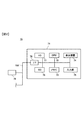
図1は、第1実施形態のマスクデータ生成方法の処理工程を表すフローチャートを示す図である。第1実施形態のマスクデータ生成方法は、図2に示すデータ処理装置70に格納されたマスクデータ生成プログラムを、データ処理装置70のコンピュータ71に搭載されるCPU72に実行させることにより、マスクデータを生成する。
図1は、第1実施形態のマスクデータ生成方法の処理工程を表すフローチャートを示す図である。第1実施形態のマスクデータ生成方法は、図2に示すデータ処理装置70に格納されたマスクデータ生成プログラムを、データ処理装置70のコンピュータ71に搭載されるCPU72に実行させることにより、マスクデータを生成する。
従って、以下では、マスクデータ生成プログラムがCPU72を制御して行う処理について説明することで、マスクデータ生成方法の実施形態について説明する。
マスクデータ生成プログラム(以下、単に「プログラム」とも呼ぶ)は、コンピュータ71のメモリ73またはハードディスク(HD)77に格納されている。
マスクデータ生成プログラム(以下、単に「プログラム」とも呼ぶ)は、コンピュータ71のメモリ73またはハードディスク(HD)77に格納されている。
ステップS101において、CPU72が、プログラムに従って、インターフェース(I/F)等を制御して、ピクセルベースのマスクデータである、後述する第1マスクデータを、メモリ73またはHD77にロードする。第1マスクデータは、例えばコンピュータ71に含まれる光学ドライブ(OD)76から読み込んでも良く、ネットワーク回線NWを介して、サーバ79または不図示の通信回線上のサーバからダウンロードしても良い。
なお、以下の各ステップにおいても、CPU72がプログラムに従って、コンピュータ71の各部を制御するが、以下の各ステップの説明では実行主体であるCPU72への言及は省略する。
なお、以下の各ステップにおいても、CPU72がプログラムに従って、コンピュータ71の各部を制御するが、以下の各ステップの説明では実行主体であるCPU72への言及は省略する。
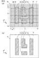
図3(a)は、第1マスクデータ20の一例を示す図である。第1マスクデータ20は、2次元の配列データ(2次元グリッド)であって、一例として、その配列変数のアドレスをXアドレス(X1~XN)およびYアドレス(Y1~YM)で表している。従って、第1マスクデータ20の単位要素であるピクセルPは、2次元グリッド上でP(Xj,Yk)として特定される。ここで、添字のjの変域は、0以上かつ自然数N以下の自然数であり、添字のkの変域は0以上かつ自然数M以下の自然数である。
ここで、Xアドレスは、第1マスクデータ20が不図示のマスク上に形成された際のマスク上のX方向の位置に対応し、Yアドレスはマスク上のX方向と直交するY方向の位置に対応する。
第1マスクデータ20の各ピクセルPの値は、一例として、+1または-1のいずれかである。これらの値は、第1マスクデータ20を用いて形成されるマスクにおける光の振幅透過率または振幅反射率の値に対応している。
第1マスクデータ20の各ピクセルPの値は、一例として、+1または-1のいずれかである。これらの値は、第1マスクデータ20を用いて形成されるマスクにおける光の振幅透過率または振幅反射率の値に対応している。
以下では、値が+1のピクセル(図3(a)中でドットを付していないピクセルP)を正ピクセルPPと呼び、値が-1のピクセル(図3(a)中でドットを付したピクセルP)を負ピクセルMPと呼ぶ。負ピクセルMPに値は、正ピクセルPPの値の-1倍である。
上述の+1の値を第1の値ということもでき、値が+1に設定されている正ピクセルPPを第1単位要素ということもできる。上述の-1の値を第2の値ということもでき、値が-1に設定されている負ピクセルMPを第2単位要素ということもできる。
図3(b)は、パターンが多角形で構成される多角形マスクデータ10の一例を比較のために示した図である。多角形マスクデータ10は、一例としてマスクの透過率分布に相当するデータであり、透過率が1(100%)程度に高い透過領域12の中に、透過率が低い遮光領域11a~11dを含むデータである。遮光領域11a~11dを、合わせて、または単独で、単に遮光領域11とも呼ぶ。
第1マスクデータ20を示す図3(a)においては、図3(b)の多角形マスクデータ10の遮光領域11a~11dのそれぞれに対応する部分を、減光領域21a~21dとして破線で囲って示している。減光領域21a~21dを、合わせて、または単独で、単に減光領域21とも呼ぶ。
第1マスクデータ20に基づいて製造されたマスクを投影露光装置に装填して得られる投影像は、減光領域21内およびその周辺に配置されている複数のピクセルPをそれぞれ透過した光の間の干渉により、減光領域21に相当する部分の光強度が低下する。
従って、図3(a)に示した第1マスクデータ20に基づくマスクを使用すると、図3(b)に示した多角形マスクデータ10に基づくマスクを使用する場合と、概ね同様の投影像を得ることができる。
従って、図3(a)に示した第1マスクデータ20に基づくマスクを使用すると、図3(b)に示した多角形マスクデータ10に基づくマスクを使用する場合と、概ね同様の投影像を得ることができる。
ただし、より好ましい投影像を得るためには、第1マスクデータ20の正ピクセルPPと負ピクセルMPとの配置を改善し、投影像の減光領域21内に相当する領域をより好ましく減光する必要がある。そこで以下のステップを実行することにより、正ピクセルPPと負ピクセルMPとの配置を修正する。
ステップS102では、始めに、CPU72が第1マスクデータ20に基づいて製造されたマスクを投影露光装置に装填した場合に得られる投影像(以下では、単に「第1マスクデータ20の投影像」とも呼ぶ)の強度分布を算出する。投影像の強度分布の算出方法は、周知の方法であるので、ここでは説明を省略する。なお、強度分布の算出は、第1マスクデータ20に基づいて製造されたマスクが使用される投影露光装置の露光波長、開口数、照明条件、残存収差等の光学条件を用いて行う。また、正ピクセルPPまたは負ピクセルMPが複数に渡って連続して分布する部分に対応する投影像の光強度が所定の値(例えば1)になるように、光強度(強度分布)のスケールを設定する。
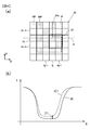
図4(a)は、図3(a)に示した第1マスクデータ20の一部分である領域22を拡大して示す図であり、図4(b)は、算出された第1マスクデータ20の投影像のうち図4(a)中の線分Aに相当する部分での強度分布IC1を示す図である。図4(b)に示すグラフの縦軸Iは、投影像の光強度を示している。
図4(b)には、図3(b)に示した多角形マスクデータ10に基づいて製造されたマスクを投影露光装置に装填した場合に得られる投影像(以下では、単に「多角形マスクデータ10の投影像」とも呼ぶ)での、図4(a)中の線分Aに対応する部分での強度分布IRも合わせて示している。以下では、多角形マスクデータ10の投影像の強度分布IRを「基準像の強度分布IR」とも呼ぶ。基準像の強度分布IRは、ステップS102を実行する前に、予め算出しておく。基準像の強度分布IRの算出方法も周知であるため、ここでは説明は省略する。
なお、基準像の強度分布IRの算出に際しても、多角形マスクデータ10に基づくマスクが使用される投影露光装置の露光波長、開口数、照明条件、残存収差等の光学条件を用いて行う。また、大面積の透過領域12部分に対応する投影像の光強度が上述の所定の値になるように、光強度(強度分布)のスケールを設定する。
第1マスクデータ20は、正ピクセルPPと負ピクセルMPとの配置の最適化が未完のため、第1マスクデータ20の投影像の強度分布IC1は、基準像の強度分布IRとは、やや乖離したものとなる。この乖離量を定量化して第1評価値を算出し、第1マスクデータ20における正ピクセルPPと負ピクセルMPとの配置の最適化の程度を推定するパラメーターとする。
第1評価値としては、一例として、第1マスクデータ20の投影像の強度分布IC1と基準像の強度分布IRとの差分D1の二乗和を用いる。すなわち、第1マスクデータ20の投影像が算出されるX座標およびY座標の各点(X,Y)で、第1マスクデータ20の投影像の強度分布IC1と基準像の強度分布IRとの差分D1の二乗を求め、これをX座標およびY座標の所定の範囲に渡って積分した値を用いる。
なお、図4(a)および図4(b)では領域22を例示して説明しているが、第1評価値は、差分D1の二乗和を、図3(a)に示した第1マスクデータ20のXアドレスおよびYアドレスの全域に対応するX座標およびY座標の範囲で積算して算出する。
なお、図4(a)および図4(b)では領域22を例示して説明しているが、第1評価値は、差分D1の二乗和を、図3(a)に示した第1マスクデータ20のXアドレスおよびYアドレスの全域に対応するX座標およびY座標の範囲で積算して算出する。
第1評価値は、上述の第1マスクデータ20の投影像の強度分布IC1と基準像の強度分布IRとの差分D1の二乗和に限られるわけではない。例えば、図3(b)に示した多角形マスクデータ10の値そのものとの差分の二乗和を用いても良い。
ステップS103以降で、正ピクセルPPと負ピクセルMPとの配置の改善を行う。
実施形態のマスクデータ生成方法においては、後述するように、図4(a)に示した第1マスクデータ20内の注目範囲23内に配置されている複数のピクセルPの正ピクセルPPと負ピクセルMPとを入れ換えることにより、改善を行う。
実施形態のマスクデータ生成方法においては、後述するように、図4(a)に示した第1マスクデータ20内の注目範囲23内に配置されている複数のピクセルPの正ピクセルPPと負ピクセルMPとを入れ換えることにより、改善を行う。
ステップS103においては、注目範囲23のYアドレスであるYkのループを開始する。このループにおいて、YアドレスであるYkは1からMまで順に変化する。
次のステップS104においては、注目範囲23のXアドレスであるXjの値のループを開始する。このループにおいて、XアドレスであるXjは1からNまで順に変化する。
次のステップS104においては、注目範囲23のXアドレスであるXjの値のループを開始する。このループにおいて、XアドレスであるXjは1からNまで順に変化する。
ステップS105においては、CPU72は、第1マスクデータ20の2次元グリッド上のアドレスXj,Ykで指定されるピクセルP(Xj,Yk)および近傍のピクセルPに、正ピクセルPPと負ピクセルMPが混在するか否かを判断する。この判断における近傍の範囲とは、図4(a)に注目範囲23として太線枠で示した範囲であり、例えば、P(Xj,Yk)、P(Xj,Yk+1)、P(Xj+1,Yk)およびP(Xj+1,Yk+1)の、2行2列の計4つのピクセルPを含む範囲である。
注目範囲23に、正ピクセルPPと負ピクセルMPが混在する場合には、ステップS106に進む。一方、混在しない場合、すなわち、注目範囲23内のピクセルPが、全て正ピクセルPPであるか、または全て負ピクセルMPである場合には、ステップS111に進む。
なお、ステップS105において、さらに、P(Xj,Yk)とP(Xj+1,Yk+1)との値が等しく、かつP(Xj,Yk+1)とP(Xj+1,Yk)との値が等しい場合に限って、正ピクセルPPと負ピクセルMPが混在すると判断しても良い。
ステップS106においては、第1マスクデータ20の注目範囲23に含まれる正ピクセルPPの値を-1に変更して負ピクセルMPとし、負ピクセルMPの値を+1に変更して正ピクセルPPとすることにより、第2マスクデータを生成する。すなわち、注目範囲23における正ピクセルPPと負ピクセルMPの配置を入れ換えて、第2マスクデータを生成する。
図5(a)は、生成した第2マスクデータ25の一部を示す図であり、第2マスクデータ25のうち、図4(a)に示した第1マスクデータ20の一部分である領域22に相当する部分を示している。
第2マスクデータ25においては、注目範囲23内の正ピクセルPPと負ピクセルMPの配置は、第1マスクデータ20における配置とは入れ換わっている。
第2マスクデータ25においては、注目範囲23内の正ピクセルPPと負ピクセルMPの配置は、第1マスクデータ20における配置とは入れ換わっている。
ステップS107において、CPU72は、第2マスクデータ25に基づいて製造されたマスクを投影露光装置に装填した場合に得られる投影像(以下では、単に「第2マスクデータ25の投影像」とも呼ぶ)の強度分布を算出する。投影像の強度分布の算出方法は、上述の第1マスクデータ20の投影像の算出方法と同様である。
図5(b)は、図4(b)と同様に、算出された第2マスクデータ25の投影像のうち図5(a)中の線分Aに相当する部分での強度分布IC2、および上述の多角形マスクデータ10の投影像の強度分布(基準像の強度分布)IRを示す図である。
図5(b)は、図4(b)と同様に、算出された第2マスクデータ25の投影像のうち図5(a)中の線分Aに相当する部分での強度分布IC2、および上述の多角形マスクデータ10の投影像の強度分布(基準像の強度分布)IRを示す図である。
そして、CPU72は、上述の第1評価値の算出と同様にして、第2マスクデータ25の投影像の強度分布IC2と基準像の強度分布IRとの乖離量を定量化する第2評価値を算出する。第2評価値として、上述の第1評価値と同様に、例えば、第2マスクデータ25の投影像の強度分布IC2と基準像の強度分布IRとの差分D2の二乗和を用いる。
ステップS108において、CPU72は、第1評価値と第2評価値とを比較する。上述のように、第1評価値および第2評価値が基準像からの乖離を表す量であるので、第1マスクデータ20または第2マスクデータ25のうち、より小さな第1評価値または第2評価値を有するマスクデータが、より好ましいマスクデータであるといえる。
従って、第2評価値が第1評価値より小さい(比較の判断がYes)場合には、第2マスクデータ25がより好ましいマスクデータである。従って、CPU72は、ステップS109に進み、第2マスクデータ25を第1マスクデータ20に代入する。これにより、第1マスクデータ20は、より好ましいデータに書き換えられる。そして、ステップS110において、CPU72は、第2評価値を第1評価値に代入する。そして、ステップS111に進む。
一方、ステップS108において第2評価値が第1評価値以上である(比較の判断がNo)場合には、第1マスクデータ20がより好ましいマスクデータであるため、CPU72は、ステップS109、ステップS110に進むことなく、ステップS111に進む。
ステップS111は、注目範囲23のXアドレスであるXjの値のループの終点であり、Xjの値を1増加して、Xjの値がN以下であればステップS104に戻り、Xjの値がNを超えていればステップS112に進む。
ステップS112は、注目範囲23のYアドレスであるYkの値のループの終点であり、Ykの値を1増加して、Ykの値がM以下であればステップS103に戻り、Ykの値がMを超えていればステップS113に進む。
ステップS112は、注目範囲23のYアドレスであるYkの値のループの終点であり、Ykの値を1増加して、Ykの値がM以下であればステップS103に戻り、Ykの値がMを超えていればステップS113に進む。
ステップS113において、CPU72は、ステップS102において算出し、ステップS109において書き換えた第1評価値が、所定の基準値よりも小さいか否かを判断する。判断結果がYes、すなわち、第1評価値が所定の基準値よりも小さい場合には、第1マスクデータ20の改善が終了したとして、ステップS114に進む。一方、判断結果がNo、すなわち、第1評価値が所定の基準値よりも小さくない場合には、第1マスクデータ20の改善は未終了であるとして、ステップS103に戻る。
所定の基準値は、例えば、オペレータがコンピュータ71の入力部75から入力しても良く、ネットワーク回線NWを介して外部から入力されるものであっても良い。
所定の基準値は、例えば、オペレータがコンピュータ71の入力部75から入力しても良く、ネットワーク回線NWを介して外部から入力されるものであっても良い。
ステップS114において、CPU72は、第1マスクデータを出力データとして出力する。出力データの出力先は、コンピュータ71に含まれる光学ドライブ(OD)76であっても良く、ネットワーク回線NWを介して、サーバ79または不図示の通信回線上のサーバに出力しても良い。
以上の各ステップにより、出力データとしてのマスクデータが生成される。
以上の各ステップにより、出力データとしてのマスクデータが生成される。
なお、上述のステップS114において出力される出力データは、ステップS108における第1評価値と第2評価値との比較の結果に基づいて選定された第1マスクデータ20または第2マスクデータ25のいずれか一方である。
なお、上述のステップS105およびステップS106において、上述の近傍の範囲である注目範囲23の範囲は、上述の4つのピクセルPに限られるわけではない。例えば、近傍の範囲である注目範囲23の範囲は、P(Xj,Yk)および、P(Xj,Yk+1)またはP(Xj,Yk-1)の2つのピクセルPを含む範囲であっても良く、P(Xj,Yk)、およびP(Xj+1,Yk)またはP(Xj-1,Yk)の2つのピクセルPを含む範囲であっても良い。あるいは、P(Xj,Yk)を中心として、アドレスX方向およびアドレスY方向に、それぞれ±1から±3程度の範囲のアドレスに含まれるピクセルPを含む範囲であっても良い。
注目範囲23の範囲内に4つ以上のピクセルPが含まれる場合には、ステップS106において、複数の正ピクセルPPおよび負ピクセルMPの値を入れ換えて第2マスクデータを生成することになる。
なお、上述の近傍の範囲である注目範囲23の範囲の上限は、一例として、第1マスクデータ20の2次元グリッド上で、第1マスクデータ20のいわゆるデザインルールの長さに相当する長さの2倍程度の距離である。すなわち、第1マスクデータ20が、一例としてデザインルール45nmのマスク用のデータであって、グリッドサイズが被露光基板(ウエハ)上換算で15nmでなら、注目範囲23の範囲は2×45nm/15nm=6アドレスの範囲となる。これは、P(Xj,Yk)を中心として、アドレスX方向およびアドレスY方向に、それぞれ±3アドレス程度の範囲となる。
なお、上述の第1実施形態は、ステップS103、ステップS104、ステップS111、およびステップS112からなるXj、Ykについてのループを有するものとしたが、このループは必ずしも設けなくても良い。すなわち、ステップS101およびステップS102において、第1マスクデータ20に関する第1評価値を算出し、第1マスクデータ20の中の1つの注目範囲23に対してステップS106からステップS109を実行し、その後ステップS114を実行しても良い。
なお、上述の第1実施形態において、ステップS101においてロードする第1マスクデータ20は、上述の非特許文献1に記載される方法を用いて、ある程度まで最適化されたピクセルベースのマスクデータであっても良い。非特許文献1に記載される方法は、シミュレーテッドアニーリングを使用してマスクデータを最適化するため、最適化に長時間を要する。しかし、上述の非特許文献1に記載される方法による最適化を、ある程度で打ち切り、その後、上述の第1実施形態によるマスクデータ生成を適用することにより、より短時間でマスクデータを生成することができる。
あるいは、上述の第1実施形態において、ステップS101においてロードする第1マスクデータ20として、それに含まれる複数の減光部分21a~21dのそれぞれに概ね最適化された部分マスクデータを繋ぎ合わせて合体したマスクデータを用いても良い。
この場合、上述の第1実施形態においては、基本的には、複数の減光部分21a~21dの周辺近傍に相当する部分のピクセルPのデータを修正すれば良いので、より短時間で、マスクデータを生成することができる。
この場合、上述の第1実施形態においては、基本的には、複数の減光部分21a~21dの周辺近傍に相当する部分のピクセルPのデータを修正すれば良いので、より短時間で、マスクデータを生成することができる。
上述の第1実施形態においては、第1マスクデータ20および第2マスクデータ25は、いずれも+1と-1の2値を取るデータであるとしたが、これに限らず、0と1の2値を取るデータであっても良い。また、比較対象となる多角形マスクデータ10についても、上述の明暗マスクパターンに限らず、他の領域に対して振幅透過率が負となる、いわゆる位相シフトマスクのマスクパターンであっても良い。
(マスクデータ生成方法の実施形態の効果)
(1)上述のマスクデータ生成方法の実施形態は、2次元グリッドを構成する複数の単位要素(ピクセルP)のそれぞれに、第1の値(+1)、または第1の値とは異なる第2の値(-1または0)が設定されている第1マスクデータ20に基づく投影像IC1の第1評価値を算出し、第1マスクデータ20に含まれる複数の単位要素のうち、第1の値が設定されている第1単位要素(正ピクセルPP)の値を第2の値に変更し、2次元グリッド上で第1単位要素と近接して配置され、第2の値が設定されている第2単位要素(負ピクセルMP)の値を第1の値に変更して第2マスクデータ25を生成し、第2マスクデータに基づく投影像IC2の第2評価値を算出し、第1評価値と第2評価値とを比較し、比較した結果に基づいて、第1マスクデータ20または第2マスクデータ25のいずれか一方を出力マスクデータとして選定する。
この構成により、ピクセルベースのマスクデータの中に近接して配置されている2つ以上のピクセルの値を同時に変更し、これに伴う投影像の評価値の変化に基づいて、マスクデータの改善を行うことができる。これにより、ピクセルベースのマスクデータの中の1つピクセルの値を書き換え、これに伴う投影像の評価値の変化に基づいて、マスクデータの改善を行う方法に比べ、より短時間でマスクデータを生成することができる。
(マスクデータ生成プログラムの実施形態)
上述のとおり、データ処理装置70を使用した上述のマスクデータの生成方法は、上記の機能を実現するためのプログラムをコンピュータ読み取り可能な記録媒体に記録して、この記録媒体に記録されたプログラムをコンピュータシステムであるコンピュータ71に読み込ませ、実行させる。
上述のとおり、データ処理装置70を使用した上述のマスクデータの生成方法は、上記の機能を実現するためのプログラムをコンピュータ読み取り可能な記録媒体に記録して、この記録媒体に記録されたプログラムをコンピュータシステムであるコンピュータ71に読み込ませ、実行させる。
なお、ここでいう「コンピュータシステム」とは、OS(Operating System)や周辺機器のハードウェアを含むものとする。また、「コンピュータ読み取り可能な記録媒体」とは、フレキシブルディスク、光磁気ディスク、光ディスク、メモリカード等の可搬型記録媒体、コンピュータシステムに内蔵されるハードディスク等の記憶装置のことをいう。
さらに「コンピュータ読み取り可能な記録媒体」とは、インターネット等のネットワーク回線NWや電話回線等の通信回線を介してプログラムを送信する場合の通信線のように、短時間の間、動的にプログラムを保持するもの、その場合のサーバやクライアントとなるコンピュータシステム内部の揮発性メモリのように、一定時間プログラムを保持するものを含んでもよい。
また上記のプログラムは、マスクデータを生成させるプログラムの機能の一部を実現するためのものであってもよく、さらに前述した機能をコンピュータシステムにすでに記録されているプログラムとの組み合わせにより実現するものであってもよい。
また、上述したプログラムは、CD-ROM等の記録媒体やインターネット等のデータ信号を通じて提供することができる。例えば、図2中のCPU72、メモリ73およびハードディスク77を備えるコンピュータ71は、光学ドライブODに装填されたCD-ROMを介してプログラムの提供を受ける。
また、コンピュータ71に接続されたネットワーク回線NWに接続されているサーバ79は上記プログラムを提供するサーバコンピュータとしても機能し、コンピュータ71の、メモリ73またはハードディスク77等の記録媒体にプログラムを転送する。すなわち、プログラムをデータ信号として搬送波により搬送して、ネットワーク回線NWを介して送信する。
このように、プログラムは、記録媒体や搬送波などの種々の形態のコンピュータ読み込み可能なコンピュータプログラム製品として供給できる。
なお、図1に示したフローチャートの各ステップは、必ずしもその全ての実行が必要とされるものではない。
なお、図1に示したフローチャートの各ステップは、必ずしもその全ての実行が必要とされるものではない。
(マスクデータ生成プログラムの実施形態の効果)
(2)上述のマスクデータプログラムの実施形態は、コンピュータ71を含むデータ処理装置70に対し、2次元グリッドを構成する複数の単位要素(ピクセルP)のそれぞれに、第1の値(+1)、または第1の値とは異なる第2の値(-1または0)が設定されている第1マスクデータ20を記憶領域に記憶させ、
第1マスクデータ20に基づく投影像IC1の第1評価値を算出させ、
第1マスクデータ20に含まれる複数の単位要素(ピクセルP)のうち、第1の値が設定されている第1単位要素(正ピクセルPP)の値を第2の値に変更し、2次元グリッド上で第1単位要素と近接して配置され、第2の値が設定されている第2単位要素(負ピクセルMP)の値を第1の値に変更して第2マスクデータ25を生成させ、
第2マスクデータに基づく投影像IC2の第2評価値を算出させ、第1評価値と第2評価値とを比較し、比較した結果に基づいて、第1マスクデータ20または第2マスクデータ25のいずれか一方を出力マスクデータとして選定させる。
この構成により、ピクセルベースのマスクデータの中に近接して配置されている2つ以上のピクセルの値を同時に変更し、これに伴う投影像の評価値の変化に基づいて、マスクデータの改善を行うことができる。これにより、ピクセルベースのマスクデータの中の1つピクセルの値を書き換え、これに伴う投影像の評価値の変化に基づいて、マスクデータの改善を行うプログラムに比べ、より短時間でマスクデータを生成することができる。
上記では、種々の実施形態および変形例を説明したが、本発明はこれらの内容に限定されるものではない。また、各実施形態および変形例は、それぞれ単独で適用しても良いし、組み合わせて用いても良い。本発明の技術的思想の範囲内で考えられるその他の態様も本発明の範囲内に含まれる。
次の優先権基礎出願の開示内容は引用文としてここに組み込まれる。
日本国特願2020-026419号(2020年2月19日出願)
次の優先権基礎出願の開示内容は引用文としてここに組み込まれる。
日本国特願2020-026419号(2020年2月19日出願)
10:多角形マスクデータ、11:遮光領域、20:ピクセルベースのマスクデータ(第1マスクデータ)、21:減光領域、23:注目範囲、P:ピクセル、PP:正ピクセル、MP:負ピクセル、IC1,IC2:投影像の強度分布、IR:基準像の強度分布、70:データ処理装置、71:コンピュータ、72:CPU、73:メモリ、77:ハードディスク(HD)
Claims (14)
- 2次元グリッドを構成する複数の単位要素のそれぞれに、第1の値、または前記第1の値とは異なる第2の値が設定されている第1マスクデータに基づく投影像の第1評価値を算出し、
前記第1マスクデータに含まれる複数の前記単位要素のうち、前記第1の値が設定されている第1単位要素の値を前記第2の値に変更し、前記2次元グリッド上で前記第1単位要素と近接して配置され、前記第2の値が設定されている第2単位要素の値を前記第1の値に変更して第2マスクデータを生成し、
前記第2マスクデータに基づく投影像の第2評価値を算出し、
前記第1評価値と前記第2評価値とを比較し、比較した結果に基づいて、前記第1マスクデータまたは前記第2マスクデータのいずれか一方を出力マスクデータとして選定する、
マスクデータ生成方法。 - 請求項1に記載のマスクデータ生成方法において、
前記第1単位要素の値の前記第2の値への変更、および前記第2単位要素の値の前記第1の値への変更を、複数の前記第1単位要素および複数の前記第2単位要素に対して行なう、マスクデータ生成方法。 - 請求項1または請求項2に記載のマスクデータ生成方法において、
前記出力マスクデータを前記第1マスクデータとし、かつ、
選択された前記出力マスクデータが前記第2マスクデータであれば、前記第2評価値を前記第1評価値として、
前記第2マスクデータの生成と、前記第2評価値の算出と、前記出力マスクデータの選定とを、複数回に渡って繰り返す、マスクデータ生成方法。 - 請求項1から請求項3までのいずれか一項に記載のマスクデータ生成方法において、
前記第2単位要素は、前記第1単位要素に対して前記2次元グリッド上で隣接して配置されている、マスクデータ生成方法。 - 請求項1から請求項3までのいずれか一項に記載のマスクデータ生成方法において、
前記第2単位要素は、前記第1単位要素に対して、前記2次元グリッド上で前記第1マスクデータのデザインルールの2倍以内の距離にある、マスクデータ生成方法。 - 請求項1から請求項5までのいずれか一項に記載のマスクデータ生成方法において、
前記第1評価値を算出する手法と、前記第2評価値を算出する手法とは同じ手法である、マスクデータ生成方法。 - 請求項6に記載のマスクデータ生成方法において、
前記同じ手法では、基準像の強度分布と、前記第1マスクデータまたは前記第2マスクデータの投影像の強度分布との差分に基づいて、前記第1評価値または前記第2評価値をそれぞれ算出する、マスクデータ生成方法。 - 請求項1から請求項7までのいずれか一項に記載のマスクデータ生成方法において、
前記第1の値および前記第2の値は、マスクにおける光の振幅透過率または振幅反射率に関する値であり、
前記第2の値は、前記第1の値の-1倍である、マスクデータ生成方法。 - 請求項1から請求項7までのいずれか一項に記載のマスクデータ生成方法において、
前記第1の値および前記第2の値は、マスクにおける光の振幅透過率または振幅反射率に関する値であり、
前記第1の値および前記第2の値の一方は0である、マスクデータ生成方法。 - コンピュータを含むデータ処理装置に対し、
2次元グリッドを構成する複数の単位要素のそれぞれに、第1の値、または前記第1の値とは異なる第2の値が設定されている第1マスクデータを記憶領域に記憶させ、
前記第1マスクデータに基づく投影像の第1評価値を算出させ、
前記第1マスクデータに含まれる複数の前記単位要素のうち、前記第1の値が設定されている第1単位要素の値を前記第2の値に変更し、前記2次元グリッド上で前記第1単位要素と近接して配置され、前記第2の値が設定されている第2単位要素の値を前記第1の値に変更して第2マスクデータを生成させ、
前記第2マスクデータに基づく投影像の第2評価値を算出させ、
前記第1評価値と前記第2評価値とを比較し、比較した結果に基づいて、前記第1マスクデータまたは前記第2マスクデータのいずれか一方を出力マスクデータとして選定させる、マスクデータ生成プログラム。 - 請求項10に記載のマスクデータ生成プログラムにおいて、
前記第1単位要素の値の前記第2の値への変更、および前記第2単位要素の値の前記第1の値への変更を、複数の前記第1単位要素および複数の前記第2単位要素に対して行なう、マスクデータ生成プログラム。 - 請求項10または請求項11に記載のマスクデータ生成プログラムにおいて、
前記出力マスクデータを前記第1マスクデータとし、かつ、
選択された前記出力マスクデータが前記第2マスクデータであれば、前記第2評価値を前記第1評価値として、
前記第2マスクデータの生成と、前記第2評価値の算出と、前記出力マスクデータの選定とを、複数回に渡って繰り返す、マスクデータ生成プログラム。 - 請求項10から請求項12までのいずれか一項に記載のマスクデータ生成プログラムにおいて、
前記第2単位要素は、前記第1単位要素に対して前記2次元グリッド上で隣接して配置されている、マスクデータ生成プログラム。 - 請求項10から請求項13までのいずれか一項に記載のマスクデータ生成プログラムにおいて、
前記第2単位要素は、前記第1単位要素に対して、前記2次元グリッド上で前記第1マスクデータのデザインルールの2倍以内の距離にある、マスクデータ生成プログラム。
Priority Applications (1)
| Application Number | Priority Date | Filing Date | Title |
|---|---|---|---|
| US17/796,813 US12248244B2 (en) | 2020-02-19 | 2021-02-18 | Mask data generation method and mask data generation program |
Applications Claiming Priority (2)
| Application Number | Priority Date | Filing Date | Title |
|---|---|---|---|
| JP2020026419A JP2023030230A (ja) | 2020-02-19 | 2020-02-19 | マスクデータ生成方法、およびマスクデータ生成プログラム |
| JP2020-026419 | 2020-02-19 |
Publications (1)
| Publication Number | Publication Date |
|---|---|
| WO2021167005A1 true WO2021167005A1 (ja) | 2021-08-26 |
Family
ID=77392184
Family Applications (1)
| Application Number | Title | Priority Date | Filing Date |
|---|---|---|---|
| PCT/JP2021/006127 Ceased WO2021167005A1 (ja) | 2020-02-19 | 2021-02-18 | マスクデータ生成方法、およびマスクデータ生成プログラム |
Country Status (3)
| Country | Link |
|---|---|
| US (1) | US12248244B2 (ja) |
| JP (1) | JP2023030230A (ja) |
| WO (1) | WO2021167005A1 (ja) |
Citations (6)
| Publication number | Priority date | Publication date | Assignee | Title |
|---|---|---|---|---|
| JPH086228A (ja) * | 1994-06-16 | 1996-01-12 | Dainippon Printing Co Ltd | ピクセルスクランブル画像処理装置 |
| JP2005513770A (ja) * | 2001-12-14 | 2005-05-12 | マイクロニック レーザー システムズ アクチボラゲット | 加工物にパターンを形成するための方法及び装置 |
| JP2008505363A (ja) * | 2004-07-01 | 2008-02-21 | アプライド マテリアルズ インコーポレイテッド | ラスタ走査型印刷におけるエリア・ベースの光学近接効果補正 |
| JP4695711B2 (ja) * | 2002-08-24 | 2011-06-08 | マスクレス・リソグラフィー・インコーポレーテッド | 連続直接書込み光リソグラフィ |
| JP2013213973A (ja) * | 2012-04-03 | 2013-10-17 | Internatl Business Mach Corp <Ibm> | マスクのデザイン方法、プログラムおよびマスクデザインシステム |
| JP2014182179A (ja) * | 2013-03-18 | 2014-09-29 | Dainippon Screen Mfg Co Ltd | Rip装置、画像記録装置、rip方法およびプログラム |
Family Cites Families (5)
| Publication number | Priority date | Publication date | Assignee | Title |
|---|---|---|---|---|
| JP6192372B2 (ja) * | 2013-06-11 | 2017-09-06 | キヤノン株式会社 | マスクパターンの作成方法、プログラムおよび情報処理装置 |
| KR102441582B1 (ko) * | 2015-07-23 | 2022-09-07 | 삼성전자주식회사 | Mpc 검증 방법 및 그 검증 방법을 포함한 마스크 제조방법 |
| JP2020060666A (ja) * | 2018-10-10 | 2020-04-16 | キオクシア株式会社 | マスクパターン補正システム、及び該補正システムを利用する半導体製造方法 |
| KR102688569B1 (ko) * | 2018-12-13 | 2024-07-25 | 삼성전자주식회사 | 마스크 레이아웃 설계 방법, opc 방법, 및 그 opc 방법을 이용한 마스크 제조방법 |
| US10877367B2 (en) * | 2019-08-30 | 2020-12-29 | Intel Corporation | Adaptive algorithm to generate optical proximity correction lithographic recipe |
-
2020
- 2020-02-19 JP JP2020026419A patent/JP2023030230A/ja active Pending
-
2021
- 2021-02-18 WO PCT/JP2021/006127 patent/WO2021167005A1/ja not_active Ceased
- 2021-02-18 US US17/796,813 patent/US12248244B2/en active Active
Patent Citations (6)
| Publication number | Priority date | Publication date | Assignee | Title |
|---|---|---|---|---|
| JPH086228A (ja) * | 1994-06-16 | 1996-01-12 | Dainippon Printing Co Ltd | ピクセルスクランブル画像処理装置 |
| JP2005513770A (ja) * | 2001-12-14 | 2005-05-12 | マイクロニック レーザー システムズ アクチボラゲット | 加工物にパターンを形成するための方法及び装置 |
| JP4695711B2 (ja) * | 2002-08-24 | 2011-06-08 | マスクレス・リソグラフィー・インコーポレーテッド | 連続直接書込み光リソグラフィ |
| JP2008505363A (ja) * | 2004-07-01 | 2008-02-21 | アプライド マテリアルズ インコーポレイテッド | ラスタ走査型印刷におけるエリア・ベースの光学近接効果補正 |
| JP2013213973A (ja) * | 2012-04-03 | 2013-10-17 | Internatl Business Mach Corp <Ibm> | マスクのデザイン方法、プログラムおよびマスクデザインシステム |
| JP2014182179A (ja) * | 2013-03-18 | 2014-09-29 | Dainippon Screen Mfg Co Ltd | Rip装置、画像記録装置、rip方法およびプログラム |
Also Published As
| Publication number | Publication date |
|---|---|
| US12248244B2 (en) | 2025-03-11 |
| JP2023030230A (ja) | 2023-03-08 |
| US20230048772A1 (en) | 2023-02-16 |
Similar Documents
| Publication | Publication Date | Title |
|---|---|---|
| US10310387B2 (en) | Dynamic patterning method that removes phase conflicts and improves pattern fidelity and CDU on a two phase-pixelated digital scanner | |
| JP4237729B2 (ja) | 空間光変調器アレイの空間像を計算する方法およびシステム | |
| CN114200768B (zh) | 基于水平集算法的超分辨光刻逆向光学邻近效应修正方法 | |
| US20210181713A1 (en) | Synchronized Parallel Tile Computation for Large Area Lithography Simulation | |
| US20030140330A1 (en) | Method for correcting a mask pattern, a computer program product, a method for producing a photomask, and method for manufacturing a semiconductor device | |
| US7773287B2 (en) | Method and system for maskless lithography real-time pattern rasterization and using computationally coupled mirrors to achieve optimum feature representation | |
| JP5529391B2 (ja) | ハーフトーン型位相シフトマスク、そのハーフトーン型位相シフトマスクを有する半導体装置の製造装置、およびそのハーフトーン型位相シフトマスクを用いた半導体装置の製造方法 | |
| Ma et al. | Pixel-based OPC optimization based on conjugate gradients | |
| CN112415879B (zh) | 一种结构光场调控方法及系统 | |
| US8495524B2 (en) | Gradient-based search mechanism for optimizing photolithograph masks | |
| US10571799B1 (en) | Hessian-free calculation of product of Hessian matrix and vector for lithography optimization | |
| JP2023030230A (ja) | マスクデータ生成方法、およびマスクデータ生成プログラム | |
| US11321904B2 (en) | Methods and systems for context passing between nodes in three-dimensional modeling | |
| Poonawala et al. | Prewarping techniques in imaging: applications in nanotechnology and biotechnology | |
| CN115981095B (zh) | 一种芯片边缘放置误差确定方法、装置、设备、存储介质 | |
| CN116819911B (zh) | 掩模图案的优化方法、装置、曝光设备及存储介质 | |
| US11664194B2 (en) | Procedural electron beam lithography | |
| TWI797588B (zh) | 光罩資訊調整裝置、光罩資料調整方法以及程式 | |
| JP2010066327A (ja) | ソフトウェアマスク算定プログラムおよび投影システム | |
| WO2021256135A1 (ja) | 制御装置、方法及びプログラム | |
| JP7578139B2 (ja) | 信号処理装置、信号処理方法、プログラム、照明装置 | |
| JP2009527911A (ja) | Slmリソグラフィ:以前のopc処理を用いないk1=0.03未満までへのプリンティング | |
| CN121457407B (zh) | 形貌感知光学邻近效应修正方法、装置、存储介质及电子设备 | |
| Martinsson et al. | Rasterizing for SLM-based mask making and maskless lithography | |
| TW202328802A (zh) | 用於製造半導體裝置的電子裝置的操作方法 |
Legal Events
| Date | Code | Title | Description |
|---|---|---|---|
| 121 | Ep: the epo has been informed by wipo that ep was designated in this application |
Ref document number: 21757416 Country of ref document: EP Kind code of ref document: A1 |
|
| NENP | Non-entry into the national phase |
Ref country code: DE |
|
| NENP | Non-entry into the national phase |
Ref country code: JP |
|
| 122 | Ep: pct application non-entry in european phase |
Ref document number: 21757416 Country of ref document: EP Kind code of ref document: A1 |
|
| WWG | Wipo information: grant in national office |
Ref document number: 17796813 Country of ref document: US |