WO2021166212A1 - Electric motor - Google Patents
Electric motor Download PDFInfo
- Publication number
- WO2021166212A1 WO2021166212A1 PCT/JP2020/006998 JP2020006998W WO2021166212A1 WO 2021166212 A1 WO2021166212 A1 WO 2021166212A1 JP 2020006998 W JP2020006998 W JP 2020006998W WO 2021166212 A1 WO2021166212 A1 WO 2021166212A1
- Authority
- WO
- WIPO (PCT)
- Prior art keywords
- ventilation passage
- cross
- ventilation
- branched
- hole
- Prior art date
Links
Images


Classifications
-
- H—ELECTRICITY
- H02—GENERATION; CONVERSION OR DISTRIBUTION OF ELECTRIC POWER
- H02K—DYNAMO-ELECTRIC MACHINES
- H02K1/00—Details of the magnetic circuit
- H02K1/06—Details of the magnetic circuit characterised by the shape, form or construction
- H02K1/12—Stationary parts of the magnetic circuit
- H02K1/20—Stationary parts of the magnetic circuit with channels or ducts for flow of cooling medium
-
- H—ELECTRICITY
- H02—GENERATION; CONVERSION OR DISTRIBUTION OF ELECTRIC POWER
- H02K—DYNAMO-ELECTRIC MACHINES
- H02K1/00—Details of the magnetic circuit
- H02K1/06—Details of the magnetic circuit characterised by the shape, form or construction
- H02K1/22—Rotating parts of the magnetic circuit
- H02K1/32—Rotating parts of the magnetic circuit with channels or ducts for flow of cooling medium
-
- H—ELECTRICITY
- H02—GENERATION; CONVERSION OR DISTRIBUTION OF ELECTRIC POWER
- H02K—DYNAMO-ELECTRIC MACHINES
- H02K9/00—Arrangements for cooling or ventilating
- H02K9/02—Arrangements for cooling or ventilating by ambient air flowing through the machine
- H02K9/04—Arrangements for cooling or ventilating by ambient air flowing through the machine having means for generating a flow of cooling medium
- H02K9/06—Arrangements for cooling or ventilating by ambient air flowing through the machine having means for generating a flow of cooling medium with fans or impellers driven by the machine shaft
Definitions
- This disclosure relates to motors.
- the motor includes a shaft, a rotor fixed to the shaft and rotating integrally, and a stator facing the rotor at a radial distance.
- the temperature rise of the motor causes, for example, the deterioration of the insulation of the coil provided in the motor, the deterioration of the grease for lubricating the bearings of the motor, and the like, which may adversely affect the extension of the life of the motor.
- At least one of the rotor and the stator may have a ventilation path that is a through hole. Air flows through the above-mentioned ventilation passage and the gap between the stator core and the rotor core. As a result, the stator, rotor and the like are cooled.
- An example of this type of motor is disclosed in Patent Document 1.
- the air that has flowed into the inside due to the rotation of the fan passes through the air holes formed in the stator core and then flows out to the outside. This configuration cools the stator and rotor.
- Patent Document 1 Since heat is transferred to the air from the stator core or rotor core when the air flows through each air hole, the temperature of the air downstream of the air hole is higher than the temperature of the air upstream of the air hole. Therefore, the cooling efficiency of the rotor conductor, the stator conductor, etc. by the air emitted from the air hole is lower than the cooling efficiency of the rotor conductor, the stator conductor, etc. by the air before flowing into the air hole.
- the motor disclosed in Patent Document 1 is an open type motor, but even in a fully closed type motor, the cooling efficiency of the member located downstream of the member that becomes hot is lowered, so that the same problem arises.
- the present disclosure has been made in view of the above circumstances, and an object of the present disclosure is to provide an electric motor having high cooling efficiency.
- the motor of the present disclosure includes a shaft, a rotor, and a stator.
- the shaft is rotatably supported around a rotation axis.
- the rotor is located on the outer side of the shaft in the radial direction and rotates integrally with the shaft.
- the stator faces the rotor at radial intervals.
- At least one of the rotor and the stator has a vent that is a through hole.
- the ventilation passage has a shape branched from the upstream end to a plurality of downstream ends. The total length of the inner peripheral surfaces of the branched ventilation passages in the cross section orthogonal to the penetration direction of the ventilation passage is longer than the length of the inner peripheral surface of the non-branched ventilation passage in the cross section orthogonal to the penetration direction.
- the motor of the present disclosure includes a ventilation passage having a branched shape. Since the total length of the inner peripheral surfaces of the branched ventilation passages is longer than the length of the inner peripheral surfaces of the non-branched ventilation passages, an electric motor having high cooling efficiency can be obtained.
- FIG. 1 is a cross-sectional view taken along the line AA of the electric motor according to the first embodiment.
- FIG. 1 is a cross-sectional view taken along the line BB of the electric motor according to the first embodiment.
- FIG. 2 is a cross-sectional view taken along the line CC of the electric motor according to the first embodiment.
- FIG. 7 is a cross-sectional view taken along the line DD of the electric motor according to the third embodiment.
- FIG. 1 is a cross-sectional view taken along the line AA of the electric motor according to the first embodiment.
- FIG. 1 is a cross-sectional view taken along the line BB of the electric motor according to the first embodiment.
- FIG. 2 is a cross-sectional view taken along the line CC of the electric motor according to the first embodiment.
- FIG. 7 is a cross-sectional view taken along the line EE of the electric motor according to the third embodiment.
- FIG. 8 is a cross-sectional view taken along the line FF of the electric motor according to the third embodiment.
- the electric motor according to the first embodiment will be described by taking an electric motor used for driving a railway vehicle as an example.
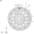
- the electric motor according to the first embodiment is shown in FIG.
- the Z-axis is in the vertical direction
- the Y-axis is parallel to the rotation axis AX of the shaft 11
- the X-axis is orthogonal to the Y-axis and the Z-axis.
- the rotation axis AX is shown by a alternate long and short dash line.
- the motor 1 shown in FIG. 1 includes a shaft 11 rotatably supported around the rotation shaft AX, a rotor 12 located outside the shaft 11 in the radial direction and rotating integrally with the shaft 11, and a rotor 12.
- a stator 13 facing in the radial direction and a fan 14 rotating integrally with the shaft 11 are provided.
- the stator core 17 of the stator 13 is formed with a ventilation passage which is a through hole having a shape that branches from the upstream end to a plurality of downstream ends. Therefore, in the cross section orthogonal to the penetrating direction of the ventilation passage, the length of the inner peripheral surface of the ventilation passage is longer than that of the upstream portion of the ventilation passage. As a result, the cooling efficiency in the downstream portion of the ventilation path is improved.
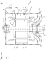
- the electric motor 1 further includes a frame 19 having an inflow hole 19a for allowing the outside air to flow in and an outflow hole 19b for allowing the inflow air to flow out to the outside. Further, the electric motor 1 includes a first bracket 20 fixed to the frame 19 and a second bracket 21 fixed to the frame 19 in a state of facing the first bracket 20 in a direction parallel to the rotation axis AX. The first bracket 20 and the second bracket 21 are located so as to sandwich the rotor 12, the stator 13, and the fan 14. The motor 1 further includes bearings 22 and 23 that rotatably support the shaft 11. Further, it is preferable that the motor 1 is provided with a cover 27 that covers the inflow hole 19a in order to prevent foreign matter such as dust and moisture from entering the inside.
- One end of the shaft 11 near the first bracket 20 is connected to the axle of the railway vehicle via joints and gears (not shown), and the rotation of the shaft 11 causes the railway vehicle to obtain power.
- the rotor 12 has a rotor core 15 fixed to the shaft 11 and a rotor conductor 16 inserted into a slot formed on the outer peripheral surface of the rotor core 15.
- the stator 13 has a stator core 17 and a coil 18 formed in the stator core 17 and inserted into a slot 17a described later.
- the stator core 17 faces the rotor core 15 in the radial direction at intervals.
- the stator core 17 has a ventilation passage 24 which is a through hole.
- FIG. 2 which is a cross-sectional view taken along the line AA of FIG. 1, a slot 17a into which the coil 18 is inserted is formed on the inner peripheral surface of the stator core 17.
- FIG. 2 in order to avoid complication of the drawing, the components of the motor 1 other than the shaft 11, the rotor core 15, the stator core 17, and the frame 19 are omitted.
- the main surface of the fan 14 shown in FIG. 1 faces the first bracket 20, and the fan 14 rotates integrally with the shaft 11.
- the first bracket 20 holds the bearing 22.
- the second bracket 21 holds the bearing 23.
- the bearings 22 and 23 rotatably support the shaft 11 around the rotation shaft AX.
- the ventilation passage 24 is located on the outer side in the radial direction from the slot 17a into which the coil 18 is inserted, extends in the direction parallel to the rotation axis AX, and penetrates the stator core 17.
- the ventilation passage 24 has a shape branched from the upstream end to a plurality of downstream ends. Specifically, as shown in FIG. 1, the ventilation passage 24 includes an upper distribution ventilation passage 24a having one end facing the second bracket 21. Further, one end of the ventilation passage 24 is upwardly distributed as shown in FIG. 3 which is a cross-sectional view taken along the line BB of FIG. 1 and FIG. 4 which is a cross-sectional view taken along the line CC of FIG.
- the ventilation passage 24 has a shape branched from the upstream end facing the second bracket 21 to a plurality of downstream ends facing the first bracket 20.
- the length of the wet edge of the branched ventilation path 24 is longer than the length of the wet edge of the non-branched ventilation path 24.
- the wet edge means the length of the wall surface of the flow path in contact with the fluid in a cross section orthogonal to the penetrating direction of the flow path. Therefore, the wet spot of the ventilation passage 24 of the electric motor 1 means the length of the inner peripheral surface of the ventilation passage 24 in the cross section orthogonal to the penetrating direction of the ventilation passage 24.
- the total length of the inner peripheral surfaces of the lower circulation air passages 24b and 24c in the XZ plane is longer than the length of the inner peripheral surface of the upper circulation air passage 24a in the XZ plane.
- the total cross-sectional area of the upper flow path 24a on the XZ plane and the cross-sectional area of the lower flow air passages 24b and 24c on the XZ plane can be regarded as being the same.
- the cross-sectional area of the ventilation passage 24 can be regarded as constant from the upstream end to the plurality of downstream ends.
- the range in which the total cross-sectional area of the upper distribution air passage 24a in the XZ plane and the cross-sectional area of the lower flow air passages 24b and 24c in the XZ plane can be considered to match is, for example, the upper flow air passage 24a in the XZ plane.
- the ratio of the cross-sectional area of the upper flow path 24a in the XZ plane to the total cross-sectional area of the lower flow paths 24b and 24c in the XZ plane is 1.0. More preferably, it is in the range of 0.9 to 1.0: 1.1.
- the shape of the XZ plane of the upper distribution air passage 24a is circular.
- the shape of the XZ plane of the lower distribution air passages 24b and 24c is a semicircle.
- the lower distribution air passages 24b and 24c are arranged so that the strings face each other on the XZ plane.
- the components of the motor 1 other than the shaft 11, the rotor core 15, the stator core 17, and the frame 19 are omitted.
- the ventilation passage 24 is formed by providing a partition member 26 for partitioning the downstream portion of the through hole inside the through hole.
- the downstream portion of the through hole means a portion downstream of the center of the through hole in the Y-axis direction.
- the shape of the cross section orthogonal to the penetrating direction of the upstream portion is a circle
- the shape of the cross section orthogonal to the penetrating direction of the downstream portion is 2 having the same diameter as the circle which is the shape of the cross section of the upstream portion.
- the ventilation passage 24 is obtained by inserting the plate-shaped partition member 26 into the through hole having a shape in which the outer edges of the two circles are connected by a straight line.
- the branching position is preferably a position closer to a plurality of downstream ends than the center of the ventilation passage 24, that is, a plurality of ends facing the first bracket 20.
- the lower distribution air passages 24b and 24c are arranged adjacent to each other. Specifically, the lower distribution air passages 24b and 24c are arranged adjacent to each other to the extent that it is possible to suppress a change in the air flow velocity due to the collision of air with the partition member 26 that branches the ventilation passage 24. Is preferable.
- the ventilation passage 24 is formed by inserting the partition member 26 into the through hole, the partition member 26 is preferably thin so as not to obstruct the air flow from the upstream to the downstream.
- the partition member 26 is preferably formed of a member having high thermal conductivity, for example, a metal such as aluminum or stainless steel. The partition member 26 may be formed integrally with the stator core 17.
- the temperatures of the stator core 17, the coil 18, the rotor core 15, and the rotor conductor 16 rise. Along with these temperature increases, the temperatures of the shaft 11 and the bearings 22 and 23 also increase.
- the motor 1 is energized and the rotor core 15 and the shaft 11 rotate integrally, the fan 14 rotates together with the shaft 11, and the air outside the motor 1 flows into the inside of the motor 1 through the inflow hole 19a.
- the air that has flowed in from the inflow hole 19a flows out of the motor 1 from the outflow hole 19b through the lower flow path 24b or the lower flow path 24c after passing through the upper flow path 24a.
- the total length of the inner peripheral surfaces of the lower distribution air passages 24b and 24c in the XZ plane is the length of the inner peripheral surface of the upper distribution air passage 24a in the XZ plane. Longer than that. Therefore, the cooling efficiency of the electric motor 1 downstream of the ventilation passage 24 is higher than that of the electric motor including the stator having the ventilation passage that is not branched. As a result, the motor 1 having high cooling efficiency can be obtained.
- the partition member 26 is formed of a member having a high thermal conductivity, it is possible to further improve the cooling efficiency downstream of the ventilation passage 24.
- the shape of the ventilation passage 24 is arbitrary as long as it has a branch and enhances the cooling efficiency in the downstream.
- the motor 2 provided with the ventilation passage 28 having a shape different from that of the motor 1 according to the first embodiment will be described in the second embodiment.
- FIG. 5 is a cross-sectional view of the motor 2 viewed in the negative direction of the Y-axis in the XZ plane passing through the upstream portion of the ventilation passage 28, similarly to FIG. Further, FIG.
- FIGS. 5 and 6 are a cross-sectional view of the motor 2 viewed in the negative direction of the Y-axis in the XZ plane passing through the downstream portion of the ventilation passage 28, similarly to FIG.
- the components of the motor 2 other than the shaft 11, the rotor core 15, the stator core 17, and the frame 19 are omitted.
- One end of the upper distribution air passage 28a faces the second bracket 21.
- one end of each of the lower circulation air passages 28b and 28c communicates with the other end of the upper distribution air passage 28a, and the other end faces the first bracket 20.
- the length of the wet edge of the branched ventilation path 28 is longer than the length of the wet edge of the non-branched ventilation path 28. Specifically, the total length of the inner peripheral surfaces of the lower circulation air passages 28b and 28c in the XZ plane is longer than the length of the inner peripheral surface of the upper circulation air passage 28a in the XZ plane.
- the total cross-sectional area of the upper flow path 28a on the XZ plane and the cross-sectional area of the lower flow air passages 28b and 28c on the XZ plane can be regarded as being the same.
- the cross-sectional area of the ventilation passage 28 can be regarded as constant from the upstream end to the plurality of downstream ends. As a result, it is suppressed that the ventilation resistance of the ventilation passage 28 increases due to the branching and the cooling efficiency decreases.
- the shape of the XZ plane of the upper distribution air passage 28a is a shape in which the outer edges of two circles having the same diameter are connected by a straight line.
- the shape of the XZ plane of the lower circulation air passages 28b and 28c is a shape obtained by equally dividing the shape of the XZ plane of the upper distribution air passage 28a by a line parallel to the Z axis.
- the lower distribution air passages 28b and 28c are arranged so that their straight portions face each other on the XZ plane.
- the ventilation passage 28 can be obtained by inserting the partition member 26 into the through hole as in the first embodiment.
- the ventilation passage 28 can be obtained by inserting the plate-shaped partition member 26 into the through hole having the shape of the XZ plane in which the outer edges of two circles having the same diameter are connected by a straight line.
- a ventilation passage 28 can be obtained in which the cross-sectional area of the cross section orthogonal to the penetrating direction of the upstream portion and the cross-sectional area of the cross section orthogonal to the penetrating direction of the downstream portion can be considered to be the same.
- the branching position is preferably a position closer to a plurality of downstream ends than the center of the ventilation passage 28, that is, a plurality of ends facing the first bracket 20.
- the lower distribution air passages 28b and 28c are arranged adjacent to each other. Specifically, the lower distribution air passages 28b and 28c are arranged adjacent to each other to the extent that it is possible to suppress a change in the air flow velocity due to the collision of air with the partition member 26 that branches the air passage 28. Is preferable.
- the ventilation passage 28 is formed by inserting the partition member 26 into the through hole, the partition member 26 is preferably thin so as not to obstruct the air flow from the upstream to the downstream.
- the total length of the inner peripheral surfaces of the lower distribution air passages 28b and 28c in the XZ plane is the length of the inner peripheral surface of the upper distribution air passage 28a in the XZ plane. Longer than that. Therefore, the cooling efficiency of the electric motor 2 downstream of the ventilation passage 28 is higher than that of the electric motor including the stator having the ventilation passage that is not branched. As a result, the motor 2 having high cooling efficiency can be obtained.
- the ventilation passages 24 and 28 are branched into two, but the ventilation passages 24 and 28 may be branched into three or more flow paths.
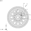
- the electric motor 3 provided with the ventilation passage 29 having a shape different from that of the first and second embodiments will be described in the third embodiment.
- the motor 3 shown in FIG. 7 includes a ventilation passage 29 having a shape branched into four from the upstream end to a plurality of downstream ends.
- the ventilation passage 29 is the upper distribution air passage 29a shown in FIG. 8 which is a cross-sectional view taken along the line DD of FIG. 7, and the cross-sectional view taken along the line EE of FIG.
- the lower distribution air passages 29b, 29c, 29d, and 29e shown in FIG. 9 are provided.
- the components of the motor 3 other than the shaft 11, the rotor core 15, the stator core 17, and the frame 19 are omitted.
- One end of the upper distribution air passage 29a faces the second bracket 21.
- one end of each of the lower distribution air passages 29b, 29c, 29d, and 29e communicates with the other end of the upper distribution air passage 29a, and the other end faces the first bracket 20.
- the length of the wet edge of the branched ventilation path 29 is longer than the length of the wet edge of the non-branched ventilation path 29. Specifically, the total length of the inner peripheral surfaces of the lower circulation air passages 29b, 29c, 29d, 29e in the XZ plane is longer than the length of the inner peripheral surface of the upper circulation air passage 29a in the XZ plane.
- the total cross-sectional area of the upper flow path 29a on the XZ plane and the cross-sectional area of the lower flow paths 29b, 29c, 29d, 29e on the XZ plane can be regarded as being the same.
- the cross-sectional area of the ventilation passage 29 can be regarded as constant from the upstream end to the plurality of downstream ends. As a result, it is suppressed that the ventilation resistance of the ventilation passage 29 increases due to the branching and the cooling efficiency decreases.
- the shape of the XZ plane of the upper distribution air passage 29a is a rectangle with rounded corners.
- the shape of the XZ plane of the lower flow passages 29b, 29c, 29d, 29e is a straight line parallel to the X axis and a straight line parallel to the Z axis of the shape of the XZ plane of the upper flow passage 29a. It is a shape obtained by dividing it into four equal parts.
- the ventilation passage 29 is formed by inserting the partition member 30 into the through hole.
- the ventilation passage 29 can be obtained by inserting the partition member 30 having a cross-shaped XZ plane into the through hole having a rectangular shape with rounded corners.
- the branching position is preferably a position closer to a plurality of downstream ends than the center of the ventilation passage 29, that is, a plurality of ends facing the first bracket 20.
- the lower distribution air passages 29b, 29c, 29d, 29e are arranged adjacent to each other.
- the lower distribution air passages 29b, 29c, 29d, and 29e are adjacent to each other to the extent that it is possible to suppress a change in the air flow velocity due to the collision of air with the partition member 30 that branches the ventilation passage 29. It is preferable that they are arranged.
- the ventilation passage 29 is formed by inserting the partition member 30 into the through hole, the plate-shaped member parallel to the XZ plane and the XY of the partition member 30 to the extent that the air flow from the upstream to the downstream is not obstructed. It is preferable that the plate-shaped members parallel to the plane are thin.
- the total length of the inner peripheral surfaces of the lower distribution air passages 29b, 29c, 29d, 29e in the XZ plane is within the upper distribution air passage 29a in the XZ plane. It is longer than the length of the peripheral surface. Therefore, the cooling efficiency of the electric motor 3 downstream of the ventilation passage 29 is higher than that of the electric motor including the stator having the ventilation passage that is not branched. As a result, the motor 3 having high cooling efficiency can be obtained.
- Ventilation passages 24, 28, and 29 penetrating the stator core 17 are formed in each of the stator cores 17 of the motor 1-3.
- a ventilation path may be formed in the air passage.
- the rotor core 15 of the motor 4 shown in FIGS. 11 and 12 has a ventilation passage 31.
- the ventilation passage 31 has a shape branched from the upstream end to a plurality of downstream ends.
- the ventilation passage 31 includes an upper distribution ventilation passage 31a whose one end faces the second bracket 21. Further, as shown in FIG.
- the ventilation passage 31 has lower circulation passages 31b and 31c having one end communicating with the other end of the upper circulation passage 31a and the other end facing the first bracket 20.
- the lower distribution air passages 31b and 31c are formed by partitioning the downstream portion of the ventilation passage 31 by the partition member 32.
- ventilation passages may be formed in both the stator core 17 and the rotor core 15.
- the rotor core 15 has a ventilation passage 31 and the stator core 17 has a ventilation passage 24.
- the shape of the ventilation passage 31 is the same as that of the motor 4 shown in FIGS. 11 and 12.
- the shape of the ventilation passage 24 is the same as that of the motor 1 according to the first embodiment.
- the ventilation passages 24, 28, 29, 31 may extend in a direction parallel to the rotation axis AX, or may extend in a direction intersecting the rotation axis AX.
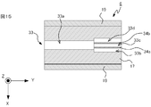
- FIG. 15 shows an electric motor 6 provided with a ventilation passage 33 formed by inserting a plurality of partition members 34a and 34b into the through holes.
- the view of FIG. 15 is the same as that of FIG.
- the ventilation passage 33 includes an upper distribution air passage 33a and a lower distribution air passage 33b, 33c, 33d.
- One end of the upper distribution air passage 33a faces the second bracket 21.
- one end of each of the lower circulation air passages 33b, 33c, 33d communicates with the other end of the upper distribution air passage 33a, and the other end faces the first bracket 20.
- the main surfaces of the partition members 34a and 34b are parallel to the YZ plane.
- the partition members 26, 30, 32, 34a, 34b may be formed of a sufficiently thin plate-shaped member. By making the partition members 26, 30, 32, 34a, 34b sufficiently thin, it is possible to suppress the change in the flow velocity of the air due to the air colliding with the partition members 26, 30, 32, 34a, 34b.
- the motor 1-6 may be a forced air-cooled motor in which the components of the motor 1-6 are cooled by the air sent from the blower provided outside to the inside. Further, the motor 1-6 may be a fully closed motor that cools the components of the motor 1-6 by circulating air inside. Further, the motor 1-6 may be a frameless type motor that does not have a frame 19. In this case, the inflow hole 19a may be formed in the second bracket 21 and the outflow hole 19b may be formed in the first bracket 20.
- 1,2,3,4,5,6 motor 11 shaft, 12 rotor, 13 stator, 14 fan, 15 rotor core, 16 rotor conductor, 17 stator core, 17a slot, 18 coil, 19 frame , 19a inflow hole, 19b outflow hole, 20 first bracket, 21 second bracket, 22,23 bearing, 24,28,29,31,33 ventilation passage, 24a, 28a, 29a, 31a, 33a upper distribution air passage, 24b, 24c, 28b, 28c, 29b, 29c, 29d, 29e, 31b, 31c, 33b, 33c, 33d Lower circulation air passage, 26, 30, 32, 34a, 34b Partition member, 27 cover, AX rotating shaft.
Landscapes
- Engineering & Computer Science (AREA)
- Power Engineering (AREA)
- Motor Or Generator Cooling System (AREA)
Abstract
An electric motor (1) is provided with: a shaft (11) that is supported rotatably about a rotational axis (AX); a rotor (12) that is located on the outside of the shaft (11) in the radial direction and rotates integrally with the shaft (11); and a stator (13) that faces the rotor (12) in the radial direction. At least either the rotor (12) or the stator (13) has a ventilation path (24) that is an through-hole. The ventilation path (24) has a branched shape. In a cross-section orthogonal to the penetration direction of the ventilation path (24), the total length of the inner circumferential surface of the branched ventilation path (24) is longer than the length of the inner circumferential surface of the ventilation path (24) that is not branched.
Description
本開示は、電動機に関する。
This disclosure relates to motors.
電動機は、シャフトと、シャフトに固定されて一体に回転する回転子と、回転子と径方向に間隔を空けて対向する固定子と、を備える。電動機に通電すると、固定子および回転子の温度が上昇する。電動機の温度上昇は、例えば、電動機が備えるコイルの絶縁の劣化の促進、電動機が備える軸受を潤滑するグリスの劣化の促進等をおこすため、電動機の寿命の延伸に悪影響を及ぼす可能性がある。
The motor includes a shaft, a rotor fixed to the shaft and rotating integrally, and a stator facing the rotor at a radial distance. When the motor is energized, the temperature of the stator and rotor rises. The temperature rise of the motor causes, for example, the deterioration of the insulation of the coil provided in the motor, the deterioration of the grease for lubricating the bearings of the motor, and the like, which may adversely affect the extension of the life of the motor.
電動機の構成要素を冷却するため、回転子および固定子の少なくともいずれかに貫通孔である通風路が形成されるものがある。空気は、上述の通風路および固定子鉄心と回転子鉄心との間の空隙等を流れる。この結果、固定子、回転子等が冷却される。この種の電動機の一例が、特許文献1に開示されている。特許文献1に開示される電動機において、ファンの回転によって内部に流入した空気は、固定子鉄心に形成された風穴を通ってから、外部に流出する。この構成により、固定子および回転子が冷却される。
In order to cool the components of the motor, at least one of the rotor and the stator may have a ventilation path that is a through hole. Air flows through the above-mentioned ventilation passage and the gap between the stator core and the rotor core. As a result, the stator, rotor and the like are cooled. An example of this type of motor is disclosed in Patent Document 1. In the motor disclosed in Patent Document 1, the air that has flowed into the inside due to the rotation of the fan passes through the air holes formed in the stator core and then flows out to the outside. This configuration cools the stator and rotor.
空気が各風穴を流れる際に固定子鉄心または回転子鉄心から空気に熱が伝達されるため、風穴の下流の空気の温度は、風穴の上流の空気の温度より高い。そのため、風穴から出た空気による回転子導体、固定子導体等の冷却効率は、風穴に流入する前の空気による回転子導体、固定子導体等の冷却効率より低い。特許文献1に開示される電動機は開放型の電動機であるが、全閉型の電動機においても、高温になる部材の下流に位置する部材の冷却効率は低下するため、同様の課題が生じる。
Since heat is transferred to the air from the stator core or rotor core when the air flows through each air hole, the temperature of the air downstream of the air hole is higher than the temperature of the air upstream of the air hole. Therefore, the cooling efficiency of the rotor conductor, the stator conductor, etc. by the air emitted from the air hole is lower than the cooling efficiency of the rotor conductor, the stator conductor, etc. by the air before flowing into the air hole. The motor disclosed in Patent Document 1 is an open type motor, but even in a fully closed type motor, the cooling efficiency of the member located downstream of the member that becomes hot is lowered, so that the same problem arises.
本開示は上述の事情に鑑みてなされたものであり、冷却効率の高い電動機を提供することを目的とする。
The present disclosure has been made in view of the above circumstances, and an object of the present disclosure is to provide an electric motor having high cooling efficiency.
上記目的を達成するために、本開示の電動機は、シャフトと、回転子と、固定子と、を備える。シャフトは、回転軸まわりに回転可能に支持される。回転子は、シャフトの径方向の外側に位置し、シャフトと一体に回転する。固定子は、回転子に径方向に間隔を空けて対向する。回転子および固定子の少なくともいずれかは、貫通孔である通風路を有する。通風路は、上流端から複数の下流端に至るまでに分岐した形状を有する。通風路の貫通方向に直交する断面における分岐している通風路の内周面の長さの合計は、貫通方向に直交する断面における分岐していない通風路の内周面の長さより長い。
In order to achieve the above object, the motor of the present disclosure includes a shaft, a rotor, and a stator. The shaft is rotatably supported around a rotation axis. The rotor is located on the outer side of the shaft in the radial direction and rotates integrally with the shaft. The stator faces the rotor at radial intervals. At least one of the rotor and the stator has a vent that is a through hole. The ventilation passage has a shape branched from the upstream end to a plurality of downstream ends. The total length of the inner peripheral surfaces of the branched ventilation passages in the cross section orthogonal to the penetration direction of the ventilation passage is longer than the length of the inner peripheral surface of the non-branched ventilation passage in the cross section orthogonal to the penetration direction.
本開示の電動機は、分岐した形状を有する通風路を備える。分岐している通風路の内周面の長さの合計は、分岐していない通風路の内周面の長さより長いため、冷却効率が高い電動機が得られる。
The motor of the present disclosure includes a ventilation passage having a branched shape. Since the total length of the inner peripheral surfaces of the branched ventilation passages is longer than the length of the inner peripheral surfaces of the non-branched ventilation passages, an electric motor having high cooling efficiency can be obtained.
以下、実施の形態に係る電動機について図面を参照して詳細に説明する。なお図中、同一または同等の部分には同一の符号を付す。
Hereinafter, the electric motor according to the embodiment will be described in detail with reference to the drawings. In the figure, the same or equivalent parts are designated by the same reference numerals.
(実施の形態1)
実施の形態1に係る電動機を、鉄道車両の駆動用に用いられる電動機を例に説明する。実施の形態1に係る電動機を図1に示す。図1において、Z軸が鉛直方向であり、Y軸は、シャフト11の回転軸AXに平行であり、X軸はY軸およびZ軸に直交する。図1において、回転軸AXを一点鎖線で示す。図1に示す電動機1は、回転軸AXまわりに回転可能に支持されるシャフト11と、シャフト11の径方向の外側に位置し、シャフト11と一体に回転する回転子12と、回転子12に径方向に対向する固定子13と、シャフト11と一体に回転するファン14と、を備える。詳細については後述するが、固定子13が有する固定子鉄心17には、上流端から複数の下流端に至るまでに分岐する形状を有する貫通孔である通風路が形成されている。このため、通風路の貫通方向に直交する断面において、通風路の内周面の長さは、通風路の上流部分と比べて長い。この結果、通風路の下流部分での冷却効率が向上する。 (Embodiment 1)
The electric motor according to the first embodiment will be described by taking an electric motor used for driving a railway vehicle as an example. The electric motor according to the first embodiment is shown in FIG. In FIG. 1, the Z-axis is in the vertical direction, the Y-axis is parallel to the rotation axis AX of theshaft 11, and the X-axis is orthogonal to the Y-axis and the Z-axis. In FIG. 1, the rotation axis AX is shown by a alternate long and short dash line. The motor 1 shown in FIG. 1 includes a shaft 11 rotatably supported around the rotation shaft AX, a rotor 12 located outside the shaft 11 in the radial direction and rotating integrally with the shaft 11, and a rotor 12. A stator 13 facing in the radial direction and a fan 14 rotating integrally with the shaft 11 are provided. Although the details will be described later, the stator core 17 of the stator 13 is formed with a ventilation passage which is a through hole having a shape that branches from the upstream end to a plurality of downstream ends. Therefore, in the cross section orthogonal to the penetrating direction of the ventilation passage, the length of the inner peripheral surface of the ventilation passage is longer than that of the upstream portion of the ventilation passage. As a result, the cooling efficiency in the downstream portion of the ventilation path is improved.
実施の形態1に係る電動機を、鉄道車両の駆動用に用いられる電動機を例に説明する。実施の形態1に係る電動機を図1に示す。図1において、Z軸が鉛直方向であり、Y軸は、シャフト11の回転軸AXに平行であり、X軸はY軸およびZ軸に直交する。図1において、回転軸AXを一点鎖線で示す。図1に示す電動機1は、回転軸AXまわりに回転可能に支持されるシャフト11と、シャフト11の径方向の外側に位置し、シャフト11と一体に回転する回転子12と、回転子12に径方向に対向する固定子13と、シャフト11と一体に回転するファン14と、を備える。詳細については後述するが、固定子13が有する固定子鉄心17には、上流端から複数の下流端に至るまでに分岐する形状を有する貫通孔である通風路が形成されている。このため、通風路の貫通方向に直交する断面において、通風路の内周面の長さは、通風路の上流部分と比べて長い。この結果、通風路の下流部分での冷却効率が向上する。 (Embodiment 1)
The electric motor according to the first embodiment will be described by taking an electric motor used for driving a railway vehicle as an example. The electric motor according to the first embodiment is shown in FIG. In FIG. 1, the Z-axis is in the vertical direction, the Y-axis is parallel to the rotation axis AX of the
電動機1はさらに、外部の空気を内部に流入させる流入孔19aと、流入した空気を外部に流出させる流出孔19bとを有するフレーム19を備える。
また電動機1は、フレーム19に固定される第1ブラケット20と、第1ブラケット20に回転軸AXに平行の方向に対向する状態でフレーム19に固定される第2ブラケット21と、を備える。なお第1ブラケット20と第2ブラケット21とは、回転子12、固定子13、およびファン14を挟んで位置する。
電動機1はさらに、シャフト11を回転可能に支持する軸受22,23を備える。
また電動機1は、内部に塵埃、水分等の異物が侵入することを抑制するため、流入孔19aを覆うカバー27を備えることが好ましい。 Theelectric motor 1 further includes a frame 19 having an inflow hole 19a for allowing the outside air to flow in and an outflow hole 19b for allowing the inflow air to flow out to the outside.
Further, theelectric motor 1 includes a first bracket 20 fixed to the frame 19 and a second bracket 21 fixed to the frame 19 in a state of facing the first bracket 20 in a direction parallel to the rotation axis AX. The first bracket 20 and the second bracket 21 are located so as to sandwich the rotor 12, the stator 13, and the fan 14.
Themotor 1 further includes bearings 22 and 23 that rotatably support the shaft 11.
Further, it is preferable that themotor 1 is provided with a cover 27 that covers the inflow hole 19a in order to prevent foreign matter such as dust and moisture from entering the inside.
また電動機1は、フレーム19に固定される第1ブラケット20と、第1ブラケット20に回転軸AXに平行の方向に対向する状態でフレーム19に固定される第2ブラケット21と、を備える。なお第1ブラケット20と第2ブラケット21とは、回転子12、固定子13、およびファン14を挟んで位置する。
電動機1はさらに、シャフト11を回転可能に支持する軸受22,23を備える。
また電動機1は、内部に塵埃、水分等の異物が侵入することを抑制するため、流入孔19aを覆うカバー27を備えることが好ましい。 The
Further, the
The
Further, it is preferable that the
電動機1の各部の詳細について説明する。シャフト11の第1ブラケット20に近い一端は、図示しない継手および歯車を介して鉄道車両の車軸に連結されており、シャフト11が回転することで、鉄道車両は動力を得る。
The details of each part of the motor 1 will be explained. One end of the shaft 11 near the first bracket 20 is connected to the axle of the railway vehicle via joints and gears (not shown), and the rotation of the shaft 11 causes the railway vehicle to obtain power.
回転子12は、シャフト11に固定される回転子鉄心15と、回転子鉄心15の外周面に形成されたスロットに挿入される回転子導体16と、を有する。回転子鉄心15がシャフト11に固定されることで、回転子鉄心15と回転子導体16を有する回転子12がシャフト11と一体に回転する。
The rotor 12 has a rotor core 15 fixed to the shaft 11 and a rotor conductor 16 inserted into a slot formed on the outer peripheral surface of the rotor core 15. By fixing the rotor core 15 to the shaft 11, the rotor 12 having the rotor core 15 and the rotor conductor 16 rotates integrally with the shaft 11.
固定子13は、固定子鉄心17と、固定子鉄心17に形成された後述のスロット17aに挿入されるコイル18と、を有する。固定子鉄心17は、回転子鉄心15と間隔を空けて径方向に対向する。また固定子鉄心17は、貫通孔である通風路24を有する。また図1のA-A線での矢視断面図である図2に示すように、固定子鉄心17の内周面にコイル18が挿入されるスロット17aが形成される。なお図2において、図の複雑化を避けるため、シャフト11、回転子鉄心15、固定子鉄心17およびフレーム19以外の電動機1の構成要素を省略した。
The stator 13 has a stator core 17 and a coil 18 formed in the stator core 17 and inserted into a slot 17a described later. The stator core 17 faces the rotor core 15 in the radial direction at intervals. Further, the stator core 17 has a ventilation passage 24 which is a through hole. Further, as shown in FIG. 2, which is a cross-sectional view taken along the line AA of FIG. 1, a slot 17a into which the coil 18 is inserted is formed on the inner peripheral surface of the stator core 17. In FIG. 2, in order to avoid complication of the drawing, the components of the motor 1 other than the shaft 11, the rotor core 15, the stator core 17, and the frame 19 are omitted.
図1に示すファン14は、主面が第1ブラケット20に面し、シャフト11と一体に回転する。
第1ブラケット20は、軸受22を保持する。
第2ブラケット21は、軸受23を保持する。
軸受22,23は、シャフト11を回転軸AXまわりに回転可能に支持する。 The main surface of thefan 14 shown in FIG. 1 faces the first bracket 20, and the fan 14 rotates integrally with the shaft 11.
Thefirst bracket 20 holds the bearing 22.
Thesecond bracket 21 holds the bearing 23.
The bearings 22 and 23 rotatably support the shaft 11 around the rotation shaft AX.
第1ブラケット20は、軸受22を保持する。
第2ブラケット21は、軸受23を保持する。
軸受22,23は、シャフト11を回転軸AXまわりに回転可能に支持する。 The main surface of the
The
The
The
通風路24は、コイル18が挿入されるスロット17aより径方向の外側に位置し、回転軸AXに平行な方向に延びて固定子鉄心17を貫通する。なお通風路24は、上流端から複数の下流端に至るまでに分岐した形状を有する。具体的には、通風路24は、図1に示すように、一端が第2ブラケット21に面する上流通風路24aを備える。さらに通風路24は、図1のB-B線での矢視断面図である図3および図2のC-C線での矢視断面図である図4に示すように、一端が上流通風路24aの他端に連通し、他端が第1ブラケット20に面する下流通風路24b,24cを有する。この構成により、通風路24は、第2ブラケット21に面する上流端から第1ブラケット20に面する複数の下流端に至るまでに分岐した形状を有する。
The ventilation passage 24 is located on the outer side in the radial direction from the slot 17a into which the coil 18 is inserted, extends in the direction parallel to the rotation axis AX, and penetrates the stator core 17. The ventilation passage 24 has a shape branched from the upstream end to a plurality of downstream ends. Specifically, as shown in FIG. 1, the ventilation passage 24 includes an upper distribution ventilation passage 24a having one end facing the second bracket 21. Further, one end of the ventilation passage 24 is upwardly distributed as shown in FIG. 3 which is a cross-sectional view taken along the line BB of FIG. 1 and FIG. 4 which is a cross-sectional view taken along the line CC of FIG. It has lower circulation air passages 24b and 24c that communicate with the other end of the air passage 24a and the other end faces the first bracket 20. With this configuration, the ventilation passage 24 has a shape branched from the upstream end facing the second bracket 21 to a plurality of downstream ends facing the first bracket 20.
分岐している通風路24のぬれぶちの長さは、分岐していない通風路24のぬれぶちの長さより長い。なお、ぬれぶちとは、流路の貫通方向に直交する断面での流体に接する流路の壁面の長さを意味する。したがって、電動機1の通風路24のぬれぶちは、通風路24の貫通方向に直交する断面での通風路24の内周面の長さを意味する。具体的には、XZ平面における下流通風路24b,24cの内周面の長さの合計は、XZ平面における上流通風路24aの内周面の長さより長い。
The length of the wet edge of the branched ventilation path 24 is longer than the length of the wet edge of the non-branched ventilation path 24. The wet edge means the length of the wall surface of the flow path in contact with the fluid in a cross section orthogonal to the penetrating direction of the flow path. Therefore, the wet spot of the ventilation passage 24 of the electric motor 1 means the length of the inner peripheral surface of the ventilation passage 24 in the cross section orthogonal to the penetrating direction of the ventilation passage 24. Specifically, the total length of the inner peripheral surfaces of the lower circulation air passages 24b and 24c in the XZ plane is longer than the length of the inner peripheral surface of the upper circulation air passage 24a in the XZ plane.
なおXZ平面における上流通風路24aの断面積と、XZ平面における下流通風路24b,24cの断面積の合計とは、一致するとみなせることが好ましい。換言すれば、通風路24の断面積は、上流端から複数の下流端に至るまで一定とみなせることが好ましい。これにより、分岐によって断面積が大きく変動することによって通風路24の通風抵抗が増大して冷却効率が低下することが抑制される。
It is preferable that the total cross-sectional area of the upper flow path 24a on the XZ plane and the cross-sectional area of the lower flow air passages 24b and 24c on the XZ plane can be regarded as being the same. In other words, it is preferable that the cross-sectional area of the ventilation passage 24 can be regarded as constant from the upstream end to the plurality of downstream ends. As a result, it is possible to prevent the ventilation resistance of the ventilation passage 24 from being increased and the cooling efficiency from being lowered due to the large variation in the cross-sectional area due to the branching.
なお、XZ平面における上流通風路24aの断面積と、XZ平面における下流通風路24b,24cの断面積の合計とが一致するとみなせる範囲としては、例えば、XZ平面における上流通風路24aの断面積と、XZ平面における下流通風路24b,24cの合計断面積との比が、1.0:0.8~1.0:1.2の範囲にある場合である。また、冷却効率が低下することをより抑制するために、XZ平面における上流通風路24aの断面積と、XZ平面における下流通風路24b,24cの合計断面積との比は、1.0:0.9~1.0:1.1の範囲にあることがより好ましい。
The range in which the total cross-sectional area of the upper distribution air passage 24a in the XZ plane and the cross-sectional area of the lower flow air passages 24b and 24c in the XZ plane can be considered to match is, for example, the upper flow air passage 24a in the XZ plane. This is the case where the ratio of the cross-sectional area to the total cross-sectional area of the lower distribution air passages 24b and 24c in the XZ plane is in the range of 1.0: 0.8 to 1.0: 1.2. Further, in order to further suppress the decrease in cooling efficiency, the ratio of the cross-sectional area of the upper flow path 24a in the XZ plane to the total cross-sectional area of the lower flow paths 24b and 24c in the XZ plane is 1.0. More preferably, it is in the range of 0.9 to 1.0: 1.1.
例えば、図2に示すように、上流通風路24aのXZ平面の形状は円形である。また図3に示すように、下流通風路24b,24cのXZ平面の形状は半円である。なお下流通風路24b,24cは、XZ平面で弦が互いに向き合って配置される。なお図3において、図の複雑化を避けるため、シャフト11、回転子鉄心15、固定子鉄心17およびフレーム19以外の電動機1の構成要素を省略した。
For example, as shown in FIG. 2, the shape of the XZ plane of the upper distribution air passage 24a is circular. Further, as shown in FIG. 3, the shape of the XZ plane of the lower distribution air passages 24b and 24c is a semicircle. The lower distribution air passages 24b and 24c are arranged so that the strings face each other on the XZ plane. In FIG. 3, in order to avoid complication of the drawing, the components of the motor 1 other than the shaft 11, the rotor core 15, the stator core 17, and the frame 19 are omitted.
例えば、図3および図4に示すように、通風路24は、貫通孔の内部に、貫通孔の下流部分を仕切る仕切り部材26を設けることで形成される。なお貫通孔の下流部分は、貫通孔のY軸方向の中央より下流側の部分を意味する。
For example, as shown in FIGS. 3 and 4, the ventilation passage 24 is formed by providing a partition member 26 for partitioning the downstream portion of the through hole inside the through hole. The downstream portion of the through hole means a portion downstream of the center of the through hole in the Y-axis direction.
具体的には、上流部分の貫通方向に直交する断面の形状が円であって、下流部分の貫通方向に直交する断面の形状が、上流部分の断面の形状である円と同一の直径の2つの円の外縁を直線で繋いだ形状である貫通孔に、板状の仕切り部材26を挿入することで、通風路24が得られる。同一の直径の2つの円の外縁を繋ぐ直線の長さと同じ長さの厚みを有する板状の仕切り部材26を設けることで、上流部分の貫通方向に直交する断面の断面積と、下流部分の貫通方向に直交する断面の断面積とが一致するとみなせる通風路24が得られる。
Specifically, the shape of the cross section orthogonal to the penetrating direction of the upstream portion is a circle, and the shape of the cross section orthogonal to the penetrating direction of the downstream portion is 2 having the same diameter as the circle which is the shape of the cross section of the upstream portion. The ventilation passage 24 is obtained by inserting the plate-shaped partition member 26 into the through hole having a shape in which the outer edges of the two circles are connected by a straight line. By providing a plate-shaped partition member 26 having the same length as the length of a straight line connecting the outer edges of two circles having the same diameter, the cross-sectional area of the cross section orthogonal to the penetrating direction of the upstream portion and the cross-sectional area of the downstream portion can be obtained. A ventilation path 24 that can be regarded as having the same cross-sectional area as the cross section orthogonal to the penetration direction is obtained.
なお分岐の位置は、通風路24の中央より複数の下流端、すなわち、第1ブラケット20に面する複数の端部に近い位置であることが好ましい。
上述の構成を有する通風路24を設けることで、通風路24の下流部分での冷却効率を、通風路24の上流部分での冷却効率より増大させることができる。 The branching position is preferably a position closer to a plurality of downstream ends than the center of theventilation passage 24, that is, a plurality of ends facing the first bracket 20.
By providing theventilation passage 24 having the above-described configuration, the cooling efficiency in the downstream portion of the ventilation passage 24 can be increased more than the cooling efficiency in the upstream portion of the ventilation passage 24.
上述の構成を有する通風路24を設けることで、通風路24の下流部分での冷却効率を、通風路24の上流部分での冷却効率より増大させることができる。 The branching position is preferably a position closer to a plurality of downstream ends than the center of the
By providing the
また下流通風路24b,24cは互いに隣接して配置されることが好ましい。具体的には、通風路24を分岐させる仕切り部材26に空気がぶつかることで、空気の流速の変化が生じることを抑制可能な程度に、下流通風路24b,24cは互いに隣接して配置されることが好ましい。通風路24が貫通孔に仕切り部材26を挿入することで形成される場合は、上流から下流に向かう空気の流れを阻害しない程度に仕切り部材26は薄いことが好ましい。
また仕切り部材26は、熱伝導率の高い部材、例えば、アルミニウム、ステンレス等の金属で形成されることが好ましい。なお仕切り部材26は、固定子鉄心17と一体に形成されてもよい。 Further, it is preferable that the lower distribution air passages 24b and 24c are arranged adjacent to each other. Specifically, the lower distribution air passages 24b and 24c are arranged adjacent to each other to the extent that it is possible to suppress a change in the air flow velocity due to the collision of air with the partition member 26 that branches the ventilation passage 24. Is preferable. When the ventilation passage 24 is formed by inserting the partition member 26 into the through hole, the partition member 26 is preferably thin so as not to obstruct the air flow from the upstream to the downstream.
Further, thepartition member 26 is preferably formed of a member having high thermal conductivity, for example, a metal such as aluminum or stainless steel. The partition member 26 may be formed integrally with the stator core 17.
また仕切り部材26は、熱伝導率の高い部材、例えば、アルミニウム、ステンレス等の金属で形成されることが好ましい。なお仕切り部材26は、固定子鉄心17と一体に形成されてもよい。 Further, it is preferable that the lower
Further, the
上記構成を有する電動機1が通電されると、固定子鉄心17、コイル18、回転子鉄心15、および回転子導体16の温度が上昇する。これらの温度上昇に伴って、シャフト11および軸受22,23の温度も上昇する。また電動機1が通電され、回転子鉄心15およびシャフト11が一体に回転すると、シャフト11と共にファン14が回転し、電動機1の外部の空気が流入孔19aから電動機1の内部に流入する。流入孔19aから流入した空気は、上流通風路24aを通ってから、下流通風路24bまたは下流通風路24cを通って流出孔19bから電動機1の外部に流出する。
When the motor 1 having the above configuration is energized, the temperatures of the stator core 17, the coil 18, the rotor core 15, and the rotor conductor 16 rise. Along with these temperature increases, the temperatures of the shaft 11 and the bearings 22 and 23 also increase. When the motor 1 is energized and the rotor core 15 and the shaft 11 rotate integrally, the fan 14 rotates together with the shaft 11, and the air outside the motor 1 flows into the inside of the motor 1 through the inflow hole 19a. The air that has flowed in from the inflow hole 19a flows out of the motor 1 from the outflow hole 19b through the lower flow path 24b or the lower flow path 24c after passing through the upper flow path 24a.
以上説明した通り、実施の形態1に係る電動機1では、XZ平面における下流通風路24b,24cの内周面の長さの合計は、XZ平面における上流通風路24aの内周面の長さより長い。このため、分岐していない通風路を有する固定子を備える電動機と比べて、電動機1が有する通風路24の下流での冷却効率は高い。この結果、冷却効率が高い電動機1が得られる。
熱伝導率の高い部材で仕切り部材26が形成される場合、通風路24の下流での冷却効率をさらに向上させることが可能である。 As described above, in themotor 1 according to the first embodiment, the total length of the inner peripheral surfaces of the lower distribution air passages 24b and 24c in the XZ plane is the length of the inner peripheral surface of the upper distribution air passage 24a in the XZ plane. Longer than that. Therefore, the cooling efficiency of the electric motor 1 downstream of the ventilation passage 24 is higher than that of the electric motor including the stator having the ventilation passage that is not branched. As a result, the motor 1 having high cooling efficiency can be obtained.
When thepartition member 26 is formed of a member having a high thermal conductivity, it is possible to further improve the cooling efficiency downstream of the ventilation passage 24.
熱伝導率の高い部材で仕切り部材26が形成される場合、通風路24の下流での冷却効率をさらに向上させることが可能である。 As described above, in the
When the
(実施の形態2)
通風路24の形状は、分岐を有し、下流での冷却効率を高める形状であれば、任意である。実施の形態1に係る電動機1とは異なる形状の通風路28を備える電動機2について実施の形態2で説明する。 (Embodiment 2)
The shape of theventilation passage 24 is arbitrary as long as it has a branch and enhances the cooling efficiency in the downstream. The motor 2 provided with the ventilation passage 28 having a shape different from that of the motor 1 according to the first embodiment will be described in the second embodiment.
通風路24の形状は、分岐を有し、下流での冷却効率を高める形状であれば、任意である。実施の形態1に係る電動機1とは異なる形状の通風路28を備える電動機2について実施の形態2で説明する。 (Embodiment 2)
The shape of the
電動機2のYZ平面での断面図は、図1と同様である。ただし電動機2が備える固定子鉄心17は通風路28を有する。
通風路28は、上流端から複数の下流端に至るまでに分岐した形状を有する。具体的には、通風路28は、図5に示す上流通風路28aと、図6に示す下流通風路28b,28cと、を備える。なお図5は、図2と同様に、通風路28の上流部分を通るXZ平面で電動機2をY軸負方向に見た断面図である。また図6は、図3と同様に、通風路28の下流部分を通るXZ平面で電動機2をY軸負方向に見た断面図である。なお図5および図6において、図の複雑化を避けるため、シャフト11、回転子鉄心15、固定子鉄心17およびフレーム19以外の電動機2の構成要素を省略した。上流通風路28aの一端は、第2ブラケット21に面する。また下流通風路28b,28cのそれぞれの一端は、上流通風路28aの他端に連通し、他端は、第1ブラケット20に面する。 The cross-sectional view of theelectric motor 2 in the YZ plane is the same as that in FIG. However, the stator core 17 included in the motor 2 has a ventilation passage 28.
Theventilation passage 28 has a shape branched from the upstream end to a plurality of downstream ends. Specifically, the ventilation passage 28 includes the upper distribution air passage 28a shown in FIG. 5 and the lower distribution air passages 28b and 28c shown in FIG. Note that FIG. 5 is a cross-sectional view of the motor 2 viewed in the negative direction of the Y-axis in the XZ plane passing through the upstream portion of the ventilation passage 28, similarly to FIG. Further, FIG. 6 is a cross-sectional view of the motor 2 viewed in the negative direction of the Y-axis in the XZ plane passing through the downstream portion of the ventilation passage 28, similarly to FIG. In FIGS. 5 and 6, in order to avoid complication of the drawings, the components of the motor 2 other than the shaft 11, the rotor core 15, the stator core 17, and the frame 19 are omitted. One end of the upper distribution air passage 28a faces the second bracket 21. Further, one end of each of the lower circulation air passages 28b and 28c communicates with the other end of the upper distribution air passage 28a, and the other end faces the first bracket 20.
通風路28は、上流端から複数の下流端に至るまでに分岐した形状を有する。具体的には、通風路28は、図5に示す上流通風路28aと、図6に示す下流通風路28b,28cと、を備える。なお図5は、図2と同様に、通風路28の上流部分を通るXZ平面で電動機2をY軸負方向に見た断面図である。また図6は、図3と同様に、通風路28の下流部分を通るXZ平面で電動機2をY軸負方向に見た断面図である。なお図5および図6において、図の複雑化を避けるため、シャフト11、回転子鉄心15、固定子鉄心17およびフレーム19以外の電動機2の構成要素を省略した。上流通風路28aの一端は、第2ブラケット21に面する。また下流通風路28b,28cのそれぞれの一端は、上流通風路28aの他端に連通し、他端は、第1ブラケット20に面する。 The cross-sectional view of the
The
分岐している通風路28のぬれぶちの長さは、分岐していない通風路28のぬれぶちの長さより長い。具体的には、XZ平面における下流通風路28b,28cの内周面の長さの合計は、XZ平面における上流通風路28aの内周面の長さより長い。
The length of the wet edge of the branched ventilation path 28 is longer than the length of the wet edge of the non-branched ventilation path 28. Specifically, the total length of the inner peripheral surfaces of the lower circulation air passages 28b and 28c in the XZ plane is longer than the length of the inner peripheral surface of the upper circulation air passage 28a in the XZ plane.
なおXZ平面における上流通風路28aの断面積と、XZ平面における下流通風路28b,28cの断面積の合計とは、一致するとみなせることが好ましい。換言すれば、通風路28の断面積は、上流端から複数の下流端に至るまで一定とみなせることが好ましい。これにより、分岐によって通風路28の通風抵抗が増大して冷却効率が低下することが抑制される。
It is preferable that the total cross-sectional area of the upper flow path 28a on the XZ plane and the cross-sectional area of the lower flow air passages 28b and 28c on the XZ plane can be regarded as being the same. In other words, it is preferable that the cross-sectional area of the ventilation passage 28 can be regarded as constant from the upstream end to the plurality of downstream ends. As a result, it is suppressed that the ventilation resistance of the ventilation passage 28 increases due to the branching and the cooling efficiency decreases.
図5に示すように、上流通風路28aのXZ平面の形状は、直径が同一の2つの円の外縁を直線で繋いだ形状である。また図6に示すように、下流通風路28b,28cのXZ平面の形状は、上流通風路28aのXZ平面の形状をZ軸に平行な線で等分して得られる形状である。なお下流通風路28b,28cは、XZ平面で直線部分が互いに向き合って配置される。
As shown in FIG. 5, the shape of the XZ plane of the upper distribution air passage 28a is a shape in which the outer edges of two circles having the same diameter are connected by a straight line. Further, as shown in FIG. 6, the shape of the XZ plane of the lower circulation air passages 28b and 28c is a shape obtained by equally dividing the shape of the XZ plane of the upper distribution air passage 28a by a line parallel to the Z axis. The lower distribution air passages 28b and 28c are arranged so that their straight portions face each other on the XZ plane.
例えば、通風路28は、実施の形態1と同様に、貫通孔に仕切り部材26を挿入することで得られる。
具体的には、XZ平面の形状が、直径が同一の2つの円の外縁を直線で繋いだ形状である貫通孔に、板状の仕切り部材26を挿入することで通風路28が得られる。下流部分のX軸方向の幅が上流部分より長い貫通孔に、貫通孔の上流部分と下流部分のX軸方向の幅の差と同じ長さのX軸方向の幅を有する板状の仕切り部材26を挿入することで、上流部分の貫通方向に直交する断面の断面積と、下流部分の貫通方向に直交する断面の断面積とが一致するとみなせる通風路28が得られる。 For example, theventilation passage 28 can be obtained by inserting the partition member 26 into the through hole as in the first embodiment.
Specifically, theventilation passage 28 can be obtained by inserting the plate-shaped partition member 26 into the through hole having the shape of the XZ plane in which the outer edges of two circles having the same diameter are connected by a straight line. A plate-shaped partition member having a width in the X-axis direction of the same length as the difference in width between the upstream part and the downstream part of the through hole in the through hole whose width in the X-axis direction of the downstream part is longer than that in the upstream part. By inserting 26, a ventilation passage 28 can be obtained in which the cross-sectional area of the cross section orthogonal to the penetrating direction of the upstream portion and the cross-sectional area of the cross section orthogonal to the penetrating direction of the downstream portion can be considered to be the same.
具体的には、XZ平面の形状が、直径が同一の2つの円の外縁を直線で繋いだ形状である貫通孔に、板状の仕切り部材26を挿入することで通風路28が得られる。下流部分のX軸方向の幅が上流部分より長い貫通孔に、貫通孔の上流部分と下流部分のX軸方向の幅の差と同じ長さのX軸方向の幅を有する板状の仕切り部材26を挿入することで、上流部分の貫通方向に直交する断面の断面積と、下流部分の貫通方向に直交する断面の断面積とが一致するとみなせる通風路28が得られる。 For example, the
Specifically, the
なお分岐の位置は、通風路28の中央より複数の下流端、すなわち、第1ブラケット20に面する複数の端部に近い位置であることが好ましい。
上述の構成を有する通風路28を設けることで、通風路28の下流部分での冷却効率を、通風路28の上流部分での冷却効率より増大させることができる。 The branching position is preferably a position closer to a plurality of downstream ends than the center of theventilation passage 28, that is, a plurality of ends facing the first bracket 20.
By providing theventilation passage 28 having the above-described configuration, the cooling efficiency in the downstream portion of the ventilation passage 28 can be increased more than the cooling efficiency in the upstream portion of the ventilation passage 28.
上述の構成を有する通風路28を設けることで、通風路28の下流部分での冷却効率を、通風路28の上流部分での冷却効率より増大させることができる。 The branching position is preferably a position closer to a plurality of downstream ends than the center of the
By providing the
また下流通風路28b,28cは互いに隣接して配置されることが好ましい。具体的には、通風路28を分岐させる仕切り部材26に空気がぶつかることで、空気の流速の変化が生じることを抑制可能な程度に、下流通風路28b,28cは互いに隣接して配置されることが好ましい。通風路28が貫通孔に仕切り部材26を挿入することで形成される場合は、上流から下流に向かう空気の流れを阻害しない程度に仕切り部材26は薄いことが好ましい。
Further, it is preferable that the lower distribution air passages 28b and 28c are arranged adjacent to each other. Specifically, the lower distribution air passages 28b and 28c are arranged adjacent to each other to the extent that it is possible to suppress a change in the air flow velocity due to the collision of air with the partition member 26 that branches the air passage 28. Is preferable. When the ventilation passage 28 is formed by inserting the partition member 26 into the through hole, the partition member 26 is preferably thin so as not to obstruct the air flow from the upstream to the downstream.
上記構成を有する電動機2が通電され、回転子鉄心15およびシャフト11が一体に回転すると、シャフト11と共にファン14が回転し、電動機2の外部の空気が流入孔19aから電動機2の内部に流入する。流入孔19aから流入した空気は、上流通風路28aを通ってから、下流通風路28bまたは下流通風路28cを通って流出孔19bから電動機2の外部に流出する。
When the motor 2 having the above configuration is energized and the rotor core 15 and the shaft 11 rotate integrally, the fan 14 rotates together with the shaft 11, and the air outside the motor 2 flows into the inside of the motor 2 from the inflow hole 19a. .. The air that has flowed in from the inflow hole 19a flows out of the electric motor 2 from the outflow hole 19b through the lower flow path 28b or the lower flow path 28c after passing through the upper flow path 28a.
以上説明した通り、実施の形態2に係る電動機2では、XZ平面における下流通風路28b,28cの内周面の長さの合計は、XZ平面における上流通風路28aの内周面の長さより長い。このため、分岐していない通風路を有する固定子を備える電動機と比べて、電動機2が有する通風路28の下流での冷却効率は高い。この結果、冷却効率が高い電動機2が得られる。
As described above, in the motor 2 according to the second embodiment, the total length of the inner peripheral surfaces of the lower distribution air passages 28b and 28c in the XZ plane is the length of the inner peripheral surface of the upper distribution air passage 28a in the XZ plane. Longer than that. Therefore, the cooling efficiency of the electric motor 2 downstream of the ventilation passage 28 is higher than that of the electric motor including the stator having the ventilation passage that is not branched. As a result, the motor 2 having high cooling efficiency can be obtained.
(実施の形態3)
実施の形態1,2では通風路24,28は2つに分岐したが、通風路24,28は、3つ以上の流路に分岐してもよい。実施の形態1,2とは異なる形状の通風路29を備える電動機3について実施の形態3で説明する。 (Embodiment 3)
In the first and second embodiments, the ventilation passages 24 and 28 are branched into two, but the ventilation passages 24 and 28 may be branched into three or more flow paths. The electric motor 3 provided with the ventilation passage 29 having a shape different from that of the first and second embodiments will be described in the third embodiment.
実施の形態1,2では通風路24,28は2つに分岐したが、通風路24,28は、3つ以上の流路に分岐してもよい。実施の形態1,2とは異なる形状の通風路29を備える電動機3について実施の形態3で説明する。 (Embodiment 3)
In the first and second embodiments, the
図7に示す電動機3は、上流端から複数の下流端に至るまでに4つに分岐した形状を有する通風路29を備える。具体的には、通風路29は、図7のD-D線での矢視断面図である図8に示す上流通風路29aと、図7のE-E線での矢視断面図である図9に示す下流通風路29b,29c,29d,29eと、を備える。なお図8および図9において、図の複雑化を避けるため、シャフト11、回転子鉄心15、固定子鉄心17およびフレーム19以外の電動機3の構成要素を省略した。上流通風路29aの一端は、第2ブラケット21に面する。また下流通風路29b,29c,29d,29eのそれぞれの一端は、上流通風路29aの他端に連通し、他端は、第1ブラケット20に面する。
The motor 3 shown in FIG. 7 includes a ventilation passage 29 having a shape branched into four from the upstream end to a plurality of downstream ends. Specifically, the ventilation passage 29 is the upper distribution air passage 29a shown in FIG. 8 which is a cross-sectional view taken along the line DD of FIG. 7, and the cross-sectional view taken along the line EE of FIG. The lower distribution air passages 29b, 29c, 29d, and 29e shown in FIG. 9 are provided. In FIGS. 8 and 9, in order to avoid complication of the drawings, the components of the motor 3 other than the shaft 11, the rotor core 15, the stator core 17, and the frame 19 are omitted. One end of the upper distribution air passage 29a faces the second bracket 21. Further, one end of each of the lower distribution air passages 29b, 29c, 29d, and 29e communicates with the other end of the upper distribution air passage 29a, and the other end faces the first bracket 20.
分岐している通風路29のぬれぶちの長さは、分岐していない通風路29のぬれぶちの長さより長い。具体的には、XZ平面における下流通風路29b,29c,29d,29eの内周面の長さの合計は、XZ平面における上流通風路29aの内周面の長さより長い。
The length of the wet edge of the branched ventilation path 29 is longer than the length of the wet edge of the non-branched ventilation path 29. Specifically, the total length of the inner peripheral surfaces of the lower circulation air passages 29b, 29c, 29d, 29e in the XZ plane is longer than the length of the inner peripheral surface of the upper circulation air passage 29a in the XZ plane.
なおXZ平面における上流通風路29aの断面積と、XZ平面における下流通風路29b,29c,29d,29eの断面積の合計とは、一致するとみなせることが好ましい。換言すれば、通風路29の断面積は、上流端から複数の下流端に至るまで一定とみなせることが好ましい。これにより、分岐によって通風路29の通風抵抗が増大して冷却効率が低下することが抑制される。
It is preferable that the total cross-sectional area of the upper flow path 29a on the XZ plane and the cross-sectional area of the lower flow paths 29b, 29c, 29d, 29e on the XZ plane can be regarded as being the same. In other words, it is preferable that the cross-sectional area of the ventilation passage 29 can be regarded as constant from the upstream end to the plurality of downstream ends. As a result, it is suppressed that the ventilation resistance of the ventilation passage 29 increases due to the branching and the cooling efficiency decreases.
図8に示すように、上流通風路29aのXZ平面の形状は、角が丸みを帯びた長方形である。また図9に示すように、下流通風路29b,29c,29d,29eのXZ平面の形状は、上流通風路29aのXZ平面の形状をX軸に平行な直線とZ軸に平行な直線とで四等分して得られる形状である。
As shown in FIG. 8, the shape of the XZ plane of the upper distribution air passage 29a is a rectangle with rounded corners. Further, as shown in FIG. 9, the shape of the XZ plane of the lower flow passages 29b, 29c, 29d, 29e is a straight line parallel to the X axis and a straight line parallel to the Z axis of the shape of the XZ plane of the upper flow passage 29a. It is a shape obtained by dividing it into four equal parts.
例えば、図8のF-F線での矢視断面図である図10に示すように、通風路29は、貫通孔に仕切り部材30を挿入することで形成される。
具体的には、XZ平面の形状が、角が丸みを帯びた長方形である貫通孔に、XZ平面の形状が十字形である仕切り部材30を挿入することで通風路29が得られる。 For example, as shown in FIG. 10 which is a cross-sectional view taken along the line FF of FIG. 8, theventilation passage 29 is formed by inserting the partition member 30 into the through hole.
Specifically, theventilation passage 29 can be obtained by inserting the partition member 30 having a cross-shaped XZ plane into the through hole having a rectangular shape with rounded corners.
具体的には、XZ平面の形状が、角が丸みを帯びた長方形である貫通孔に、XZ平面の形状が十字形である仕切り部材30を挿入することで通風路29が得られる。 For example, as shown in FIG. 10 which is a cross-sectional view taken along the line FF of FIG. 8, the
Specifically, the
なお分岐の位置は、通風路29の中央より複数の下流端、すなわち、第1ブラケット20に面する複数の端部に近い位置であることが好ましい。
上述の構成を有する通風路29を設けることで、通風路29の下流部分での冷却効率を、通風路29の上流部分での冷却効率より増大させることができる。 The branching position is preferably a position closer to a plurality of downstream ends than the center of theventilation passage 29, that is, a plurality of ends facing the first bracket 20.
By providing theventilation passage 29 having the above-described configuration, the cooling efficiency in the downstream portion of the ventilation passage 29 can be increased more than the cooling efficiency in the upstream portion of the ventilation passage 29.
上述の構成を有する通風路29を設けることで、通風路29の下流部分での冷却効率を、通風路29の上流部分での冷却効率より増大させることができる。 The branching position is preferably a position closer to a plurality of downstream ends than the center of the
By providing the
また下流通風路29b,29c,29d,29eは互いに隣接して配置されることが好ましい。具体的には、通風路29を分岐させる仕切り部材30に空気がぶつかることで、空気の流速の変化が生じることを抑制可能な程度に、下流通風路29b,29c,29d,29eは互いに隣接して配置されることが好ましい。通風路29が貫通孔に仕切り部材30を挿入することで形成される場合は、上流から下流に向かう空気の流れを阻害しない程度に、仕切り部材30が有するXZ平面に平行な板状部材およびXY平面に平行な板状部材はそれぞれ薄いことが好ましい。
Further, it is preferable that the lower distribution air passages 29b, 29c, 29d, 29e are arranged adjacent to each other. Specifically, the lower distribution air passages 29b, 29c, 29d, and 29e are adjacent to each other to the extent that it is possible to suppress a change in the air flow velocity due to the collision of air with the partition member 30 that branches the ventilation passage 29. It is preferable that they are arranged. When the ventilation passage 29 is formed by inserting the partition member 30 into the through hole, the plate-shaped member parallel to the XZ plane and the XY of the partition member 30 to the extent that the air flow from the upstream to the downstream is not obstructed. It is preferable that the plate-shaped members parallel to the plane are thin.
上記構成を有する電動機3が通電され、回転子鉄心15およびシャフト11が一体に回転すると、シャフト11と共にファン14が回転し、電動機3の外部の空気が流入孔19aから電動機3の内部に流入する。流入孔19aから流入した空気は、上流通風路29aを通ってから、下流通風路29b、下流通風路29c、下流通風路29d、または下流通風路29eを通って流出孔19bから電動機3の外部に流出する。
When the motor 3 having the above configuration is energized and the rotor core 15 and the shaft 11 rotate integrally, the fan 14 rotates together with the shaft 11, and the air outside the motor 3 flows into the inside of the motor 3 from the inflow hole 19a. .. The air flowing in from the inflow hole 19a passes through the upper flow path 29a, then passes through the lower flow path 29b, the lower flow path 29c, the lower flow path 29d, or the lower flow path 29e, and then passes through the outflow hole 19b. It flows out to the outside of the electric motor 3.
以上説明した通り、実施の形態3に係る電動機3では、XZ平面における下流通風路29b,29c,29d,29eの内周面の長さの合計は、XZ平面における上流通風路29aの内周面の長さより長い。このため、分岐していない通風路を有する固定子を備える電動機と比べて、電動機3が有する通風路29の下流での冷却効率は高い。この結果、冷却効率が高い電動機3が得られる。
As described above, in the motor 3 according to the third embodiment, the total length of the inner peripheral surfaces of the lower distribution air passages 29b, 29c, 29d, 29e in the XZ plane is within the upper distribution air passage 29a in the XZ plane. It is longer than the length of the peripheral surface. Therefore, the cooling efficiency of the electric motor 3 downstream of the ventilation passage 29 is higher than that of the electric motor including the stator having the ventilation passage that is not branched. As a result, the motor 3 having high cooling efficiency can be obtained.
本開示は上述の実施の形態に限られない。
実施の形態1-3では、電動機1-3が有する固定子鉄心17のそれぞれに、固定子鉄心17を貫通する通風路24,28,29が形成される例について説明したが、回転子鉄心15に通風路が形成されてもよい。図11および図12に示す電動機4の回転子鉄心15は、通風路31を有する。通風路31は、通風路24と同様に、上流端から複数の下流端に至るまでに分岐した形状を有する。具体的には、通風路31は、図11に示すように、一端が第2ブラケット21に面する上流通風路31aを備える。さらに通風路31は、図12に示すように、一端が上流通風路31aの他端に連通し、他端が第1ブラケット20に面する下流通風路31b,31cを有する。通風路31の下流部分が仕切り部材32によって仕切られることで、下流通風路31b,31cが形成される。 The present disclosure is not limited to the embodiments described above.
In the first embodiment, an example in which ventilation passages 24, 28, and 29 penetrating the stator core 17 are formed in each of the stator cores 17 of the motor 1-3 has been described. A ventilation path may be formed in the air passage. The rotor core 15 of the motor 4 shown in FIGS. 11 and 12 has a ventilation passage 31. Like the ventilation passage 24, the ventilation passage 31 has a shape branched from the upstream end to a plurality of downstream ends. Specifically, as shown in FIG. 11, the ventilation passage 31 includes an upper distribution ventilation passage 31a whose one end faces the second bracket 21. Further, as shown in FIG. 12, the ventilation passage 31 has lower circulation passages 31b and 31c having one end communicating with the other end of the upper circulation passage 31a and the other end facing the first bracket 20. The lower distribution air passages 31b and 31c are formed by partitioning the downstream portion of the ventilation passage 31 by the partition member 32.
実施の形態1-3では、電動機1-3が有する固定子鉄心17のそれぞれに、固定子鉄心17を貫通する通風路24,28,29が形成される例について説明したが、回転子鉄心15に通風路が形成されてもよい。図11および図12に示す電動機4の回転子鉄心15は、通風路31を有する。通風路31は、通風路24と同様に、上流端から複数の下流端に至るまでに分岐した形状を有する。具体的には、通風路31は、図11に示すように、一端が第2ブラケット21に面する上流通風路31aを備える。さらに通風路31は、図12に示すように、一端が上流通風路31aの他端に連通し、他端が第1ブラケット20に面する下流通風路31b,31cを有する。通風路31の下流部分が仕切り部材32によって仕切られることで、下流通風路31b,31cが形成される。 The present disclosure is not limited to the embodiments described above.
In the first embodiment, an example in which
また固定子鉄心17および回転子鉄心15の両方に通風路が形成されてもよい。図13および図14に示す電動機5において、回転子鉄心15は通風路31を有し、固定子鉄心17は通風路24を有する。通風路31の形状は、図11および図12に示す電動機4と同様である。通風路24の形状は、実施の形態1に係る電動機1と同様である。
Further, ventilation passages may be formed in both the stator core 17 and the rotor core 15. In the motor 5 shown in FIGS. 13 and 14, the rotor core 15 has a ventilation passage 31 and the stator core 17 has a ventilation passage 24. The shape of the ventilation passage 31 is the same as that of the motor 4 shown in FIGS. 11 and 12. The shape of the ventilation passage 24 is the same as that of the motor 1 according to the first embodiment.
通風路24,28,29,31は、回転軸AXに平行な方向に延びてもよいし、回転軸AXに交差する方向に延びてもよい。
The ventilation passages 24, 28, 29, 31 may extend in a direction parallel to the rotation axis AX, or may extend in a direction intersecting the rotation axis AX.
通風路24,28,29,31の形状は、上述の例に限られず、下流部分の冷却効率が上流部分より高い任意の形状である。一例として、貫通孔に複数の仕切り部材34a,34bを挿入することで形成された通風路33を備える電動機6を図15に示す。図15の見方は、図4と同様である。通風路33は、上流通風路33aと、下流通風路33b,33c,33dと、を備える。上流通風路33aの一端は、第2ブラケット21に面する。また下流通風路33b,33c,33dのそれぞれの一端は、上流通風路33aの他端に連通し、他端は、第1ブラケット20に面する。仕切り部材34a,34bのそれぞれの主面は、YZ平面に平行である。
The shapes of the ventilation passages 24, 28, 29, and 31 are not limited to the above examples, and are arbitrary shapes in which the cooling efficiency of the downstream portion is higher than that of the upstream portion. As an example, FIG. 15 shows an electric motor 6 provided with a ventilation passage 33 formed by inserting a plurality of partition members 34a and 34b into the through holes. The view of FIG. 15 is the same as that of FIG. The ventilation passage 33 includes an upper distribution air passage 33a and a lower distribution air passage 33b, 33c, 33d. One end of the upper distribution air passage 33a faces the second bracket 21. Further, one end of each of the lower circulation air passages 33b, 33c, 33d communicates with the other end of the upper distribution air passage 33a, and the other end faces the first bracket 20. The main surfaces of the partition members 34a and 34b are parallel to the YZ plane.
仕切り部材26,30,32,34a,34bを十分に薄い板状部材で形成してもよい。仕切り部材26,30,32,34a,34bを十分に薄くすることで、空気が仕切り部材26,30,32,34a,34bにぶつかることで、空気の流速が変化することが抑制される。
The partition members 26, 30, 32, 34a, 34b may be formed of a sufficiently thin plate-shaped member. By making the partition members 26, 30, 32, 34a, 34b sufficiently thin, it is possible to suppress the change in the flow velocity of the air due to the air colliding with the partition members 26, 30, 32, 34a, 34b.
電動機1-6は、外部に設けられたブロワから内部に送られた空気によって、電動機1-6の構成要素を冷却する強制風冷形の電動機でもよい。また電動機1-6は、内部で空気を循環させることで、電動機1-6の構成要素を冷却する全閉形の電動機でもよい。また電動機1-6は、フレーム19を有さないフレームレスタイプの電動機でもよい。この場合、第2ブラケット21に流入孔19aを形成し、第1ブラケット20に流出孔19bを形成すればよい。
The motor 1-6 may be a forced air-cooled motor in which the components of the motor 1-6 are cooled by the air sent from the blower provided outside to the inside. Further, the motor 1-6 may be a fully closed motor that cools the components of the motor 1-6 by circulating air inside. Further, the motor 1-6 may be a frameless type motor that does not have a frame 19. In this case, the inflow hole 19a may be formed in the second bracket 21 and the outflow hole 19b may be formed in the first bracket 20.
本開示は、本開示の広義の精神と範囲を逸脱することなく、様々な実施の形態及び変形が可能とされるものである。また、上述した実施の形態は、この開示を説明するためのものであり、本開示の範囲を限定するものではない。すなわち、本開示の範囲は、実施の形態ではなく、特許請求の範囲によって示される。そして、特許請求の範囲内及びそれと同等の開示の意義の範囲内で施される様々な変形が、この開示の範囲内とみなされる。
The present disclosure allows for various embodiments and modifications without departing from the broad spirit and scope of the present disclosure. Moreover, the above-described embodiment is for explaining this disclosure, and does not limit the scope of the present disclosure. That is, the scope of the present disclosure is indicated by the scope of claims, not by the embodiment. And, various modifications made within the scope of claims and the equivalent meaning of disclosure are considered to be within the scope of this disclosure.
1,2,3,4,5,6 電動機、11 シャフト、12 回転子、13 固定子、14 ファン、15 回転子鉄心、16 回転子導体、17 固定子鉄心、17a スロット、18 コイル、19 フレーム、19a 流入孔、19b 流出孔、20 第1ブラケット、21 第2ブラケット、22,23 軸受、24,28,29,31,33 通風路、24a,28a,29a,31a,33a 上流通風路、24b,24c,28b,28c,29b,29c,29d,29e,31b,31c,33b,33c,33d 下流通風路、26,30,32,34a,34b 仕切り部材、27 カバー、AX 回転軸。
1,2,3,4,5,6 motor, 11 shaft, 12 rotor, 13 stator, 14 fan, 15 rotor core, 16 rotor conductor, 17 stator core, 17a slot, 18 coil, 19 frame , 19a inflow hole, 19b outflow hole, 20 first bracket, 21 second bracket, 22,23 bearing, 24,28,29,31,33 ventilation passage, 24a, 28a, 29a, 31a, 33a upper distribution air passage, 24b, 24c, 28b, 28c, 29b, 29c, 29d, 29e, 31b, 31c, 33b, 33c, 33d Lower circulation air passage, 26, 30, 32, 34a, 34b Partition member, 27 cover, AX rotating shaft.
Claims (9)
- 回転軸まわりに回転可能に支持されるシャフトと、
前記シャフトの径方向の外側に位置し、前記シャフトと一体に回転する回転子と、
前記回転子に前記径方向に間隔を空けて対向する固定子と、
を備え、
前記回転子および前記固定子の少なくともいずれかは、貫通孔である通風路を有し、
前記通風路は、上流端から複数の下流端に至るまでに分岐した形状を有し、
前記通風路の貫通方向に直交する断面における分岐している前記通風路の内周面の長さの合計は、前記貫通方向に直交する断面における分岐していない前記通風路の内周面の長さより長い、
電動機。 A shaft that is rotatably supported around the axis of rotation,
A rotor located outside the shaft in the radial direction and rotating integrally with the shaft.
A stator facing the rotor at intervals in the radial direction,
With
At least one of the rotor and the stator has a vent that is a through hole and has a vent.
The ventilation passage has a shape branched from the upstream end to a plurality of downstream ends.
The total length of the inner peripheral surfaces of the ventilation passages that are branched in the cross section orthogonal to the penetration direction of the ventilation passage is the length of the inner peripheral surface of the ventilation passage that is not branched in the cross section orthogonal to the penetration direction. Longer than
Electric motor. - 分岐している前記通風路は互いに隣接して配置される、
請求項1に記載の電動機。 The branched ventilation passages are arranged adjacent to each other.
The motor according to claim 1. - 前記貫通方向に直交する断面における分岐している前記通風路の断面積の合計と、前記貫通方向に直交する断面における分岐していない前記通風路の断面積とは、一致するとみなせる、
請求項1または2に記載の電動機。 The total cross-sectional area of the ventilated passages that are branched in the cross section orthogonal to the penetrating direction and the cross-sectional area of the ventilated passage that is not branched in the cross section orthogonal to the penetrating direction can be regarded as being the same.
The motor according to claim 1 or 2. - 前記通風路は、前記通風路の中央より前記複数の下流端に近い位置で分岐した形状を有する、
請求項1から3のいずれか1項に記載の電動機。 The ventilation passage has a shape branched at a position closer to the plurality of downstream ends than the center of the ventilation passage.
The motor according to any one of claims 1 to 3. - 前記通風路は、前記通風路の下流部分を仕切る少なくとも1つの仕切り部材を有する、
請求項1から4のいずれか1項に記載の電動機。 The ventilation passage has at least one partition member that partitions a downstream portion of the ventilation passage.
The electric motor according to any one of claims 1 to 4. - 前記少なくとも1つの仕切り部材は、側面が前記貫通孔の内周面に当接し、前記貫通孔の下流端から前記貫通孔の貫通方向に延びる板状部材を有する、
請求項5に記載の電動機。 The at least one partition member has a plate-like member whose side surface abuts on the inner peripheral surface of the through hole and extends from the downstream end of the through hole in the penetrating direction of the through hole.
The motor according to claim 5. - 前記仕切り部材は、複数の前記板状部材を有し、
前記複数の板状部材の主面は互いに間隔を空けて平行に位置する、
請求項6に記載の電動機。 The partition member has a plurality of the plate-shaped members.
The main surfaces of the plurality of plate-shaped members are located in parallel with each other at intervals.
The motor according to claim 6. - 前記固定子は、前記回転子に前記径方向に間隔を空けて対向し、前記通風路と溝を有する固定子鉄心と、前記固定子鉄心の前記溝に挿入されるコイルと、を有し、
前記少なくとも1つの仕切り部材は、前記固定子鉄心と一体に形成されている、
請求項5から7のいずれか1項に記載の電動機。 The stator has a stator core that faces the rotor at intervals in the radial direction and has a ventilation path and a groove, and a coil that is inserted into the groove of the stator core.
The at least one partition member is formed integrally with the stator core.
The electric motor according to any one of claims 5 to 7. - 前記固定子が内周面に固定され、外部の空気を内部に流入させる流入孔と、前記流入孔から流入した前記空気を前記外部に流出させる流出孔と、を有するフレームをさらに備え、
前記流入孔から流入した前記空気は、前記通風路を通って、前記流出孔から流出する、
請求項1から8のいずれか1項に記載の電動機。 The stator is further provided with a frame having an inflow hole in which the stator is fixed to the inner peripheral surface and allows external air to flow in, and an outflow hole for allowing the air flowing in from the inflow hole to flow out to the outside.
The air that has flowed in from the inflow hole passes through the ventilation passage and flows out from the outflow hole.
The electric motor according to any one of claims 1 to 8.
Priority Applications (3)
| Application Number | Priority Date | Filing Date | Title |
|---|---|---|---|
| JP2022501547A JP7146135B2 (en) | 2020-02-21 | 2020-02-21 | Electric motor |
| PCT/JP2020/006998 WO2021166212A1 (en) | 2020-02-21 | 2020-02-21 | Electric motor |
| US17/790,998 US20230034637A1 (en) | 2020-02-21 | 2020-02-21 | Electric motor |
Applications Claiming Priority (1)
| Application Number | Priority Date | Filing Date | Title |
|---|---|---|---|
| PCT/JP2020/006998 WO2021166212A1 (en) | 2020-02-21 | 2020-02-21 | Electric motor |
Publications (1)
| Publication Number | Publication Date |
|---|---|
| WO2021166212A1 true WO2021166212A1 (en) | 2021-08-26 |
Family
ID=77390533
Family Applications (1)
| Application Number | Title | Priority Date | Filing Date |
|---|---|---|---|
| PCT/JP2020/006998 WO2021166212A1 (en) | 2020-02-21 | 2020-02-21 | Electric motor |
Country Status (3)
| Country | Link |
|---|---|
| US (1) | US20230034637A1 (en) |
| JP (1) | JP7146135B2 (en) |
| WO (1) | WO2021166212A1 (en) |
Citations (4)
| Publication number | Priority date | Publication date | Assignee | Title |
|---|---|---|---|---|
| JPH01164263A (en) * | 1987-12-18 | 1989-06-28 | Hitachi Ltd | Rotor for superconductive rotating machine |
| JPH04271264A (en) * | 1991-02-26 | 1992-09-28 | Chodendo Hatsuden Kanren Kiki Zairyo Gijutsu Kenkyu Kumiai | Rotor of superconducting generator |
| WO1999038244A1 (en) * | 1998-01-21 | 1999-07-29 | Hitachi, Ltd. | Motor |
| JP2016220395A (en) * | 2015-05-20 | 2016-12-22 | 東芝三菱電機産業システム株式会社 | Rotary electric machine |
Family Cites Families (11)
| Publication number | Priority date | Publication date | Assignee | Title |
|---|---|---|---|---|
| JPS5449520U (en) * | 1977-09-13 | 1979-04-06 | ||
| JPS57133279U (en) * | 1981-02-16 | 1982-08-19 | ||
| JPS605252U (en) * | 1983-06-23 | 1985-01-16 | 株式会社東芝 | Rotor of squirrel cage induction motor |
| JPS60151245U (en) * | 1984-03-15 | 1985-10-08 | 三菱電機株式会社 | Ventilation cooling system for rotating electrical machines |
| JPS61156447U (en) * | 1985-03-15 | 1986-09-27 | ||
| JP3521262B2 (en) * | 1998-04-14 | 2004-04-19 | 株式会社日立製作所 | Rotating electric machine |
| JP2001178050A (en) | 1999-12-14 | 2001-06-29 | Meidensha Corp | Rotor of dynamo-electric machine |
| JP4417970B2 (en) | 2007-03-29 | 2010-02-17 | 株式会社東芝 | Rotating electric machine and rotating electric machine rotor |
| JP5893462B2 (en) | 2012-03-26 | 2016-03-23 | 東芝三菱電機産業システム株式会社 | Rotating electric machine |
| EP3046225A1 (en) | 2015-01-16 | 2016-07-20 | Siemens Aktiengesellschaft | Electric rotary machine having one-sided cooling, and method for one-sided cooling |
| CN209177421U (en) | 2018-11-14 | 2019-07-30 | 辽宁工程技术大学 | A kind of external rotor permanent magnet synchronous machine for coal mine belt conveyor directly drives roller |
-
2020
- 2020-02-21 US US17/790,998 patent/US20230034637A1/en active Pending
- 2020-02-21 WO PCT/JP2020/006998 patent/WO2021166212A1/en active Application Filing
- 2020-02-21 JP JP2022501547A patent/JP7146135B2/en active Active
Patent Citations (4)
| Publication number | Priority date | Publication date | Assignee | Title |
|---|---|---|---|---|
| JPH01164263A (en) * | 1987-12-18 | 1989-06-28 | Hitachi Ltd | Rotor for superconductive rotating machine |
| JPH04271264A (en) * | 1991-02-26 | 1992-09-28 | Chodendo Hatsuden Kanren Kiki Zairyo Gijutsu Kenkyu Kumiai | Rotor of superconducting generator |
| WO1999038244A1 (en) * | 1998-01-21 | 1999-07-29 | Hitachi, Ltd. | Motor |
| JP2016220395A (en) * | 2015-05-20 | 2016-12-22 | 東芝三菱電機産業システム株式会社 | Rotary electric machine |
Also Published As
| Publication number | Publication date |
|---|---|
| JPWO2021166212A1 (en) | 2021-08-26 |
| JP7146135B2 (en) | 2022-10-03 |
| US20230034637A1 (en) | 2023-02-02 |
Similar Documents
| Publication | Publication Date | Title |
|---|---|---|
| US7629717B2 (en) | Totally-enclosed fan-cooled motor | |
| JP5342955B2 (en) | Rotating electric machine | |
| JP6665344B2 (en) | Vehicle electric motor | |
| CA2568881C (en) | Totally-enclosed fan-cooled motor | |
| JP2003143809A (en) | Totally-enclosed fan-cooled motor for vehicle | |
| JP4928986B2 (en) | Fully closed electric motor for vehicle drive | |
| JP6685464B2 (en) | Main motor for vehicle | |
| WO2021166212A1 (en) | Electric motor | |
| JP2017060319A (en) | Cooling structure for electric motor | |
| JP2006180684A (en) | Totally-enclosed motor for vehicle drive | |
| WO2018196003A1 (en) | Motor ventilation structure and motor | |
| WO2022064627A1 (en) | Electric motor | |
| JPH0823661A (en) | Cooling structure for totally-enclosed fan-cooled motor | |
| WO2020208730A1 (en) | Electric motor | |
| CN112072855B (en) | Motor | |
| JP2016100953A (en) | Rotary electric machine | |
| JP7337290B2 (en) | Electric motor | |
| US10404138B2 (en) | Rotary electric machine having gas coolers | |
| JP2005168204A (en) | Rotary electric machine | |
| JP7309091B2 (en) | Electric motor | |
| JP7145938B2 (en) | Electric motor | |
| JP7325686B2 (en) | Electric motor | |
| JP6958655B2 (en) | Rotating machine | |
| JP6976449B2 (en) | Electric motor | |
| JP7450836B1 (en) | rotating electric machine |
Legal Events
| Date | Code | Title | Description |
|---|---|---|---|
| 121 | Ep: the epo has been informed by wipo that ep was designated in this application |
Ref document number: 20919785 Country of ref document: EP Kind code of ref document: A1 |
|
| ENP | Entry into the national phase |
Ref document number: 2022501547 Country of ref document: JP Kind code of ref document: A |
|
| NENP | Non-entry into the national phase |
Ref country code: DE |
|
| 122 | Ep: pct application non-entry in european phase |
Ref document number: 20919785 Country of ref document: EP Kind code of ref document: A1 |