WO2021162086A1 - Dispositif d'injection - Google Patents
Dispositif d'injection Download PDFInfo
- Publication number
- WO2021162086A1 WO2021162086A1 PCT/JP2021/005229 JP2021005229W WO2021162086A1 WO 2021162086 A1 WO2021162086 A1 WO 2021162086A1 JP 2021005229 W JP2021005229 W JP 2021005229W WO 2021162086 A1 WO2021162086 A1 WO 2021162086A1
- Authority
- WO
- WIPO (PCT)
- Prior art keywords
- plunger
- barrel
- urging
- engaging member
- central axis
- Prior art date
Links
- 238000002347 injection Methods 0.000 title claims abstract description 136
- 239000007924 injection Substances 0.000 title claims abstract description 136
- 230000007246 mechanism Effects 0.000 claims abstract description 94
- 230000013011 mating Effects 0.000 claims description 3
- 238000005192 partition Methods 0.000 description 51
- 230000002265 prevention Effects 0.000 description 27
- 230000002093 peripheral effect Effects 0.000 description 25
- 238000003780 insertion Methods 0.000 description 22
- 230000037431 insertion Effects 0.000 description 22
- 239000002775 capsule Substances 0.000 description 13
- 239000000243 solution Substances 0.000 description 10
- 239000000126 substance Substances 0.000 description 9
- 230000001105 regulatory effect Effects 0.000 description 8
- 238000013459 approach Methods 0.000 description 4
- 230000006835 compression Effects 0.000 description 4
- 238000007906 compression Methods 0.000 description 4
- 230000009471 action Effects 0.000 description 3
- 238000010586 diagram Methods 0.000 description 3
- 230000000149 penetrating effect Effects 0.000 description 3
- 238000009751 slip forming Methods 0.000 description 3
- 230000004913 activation Effects 0.000 description 2
- 239000003814 drug Substances 0.000 description 2
- 238000001647 drug administration Methods 0.000 description 2
- NOESYZHRGYRDHS-UHFFFAOYSA-N insulin Chemical compound N1C(=O)C(NC(=O)C(CCC(N)=O)NC(=O)C(CCC(O)=O)NC(=O)C(C(C)C)NC(=O)C(NC(=O)CN)C(C)CC)CSSCC(C(NC(CO)C(=O)NC(CC(C)C)C(=O)NC(CC=2C=CC(O)=CC=2)C(=O)NC(CCC(N)=O)C(=O)NC(CC(C)C)C(=O)NC(CCC(O)=O)C(=O)NC(CC(N)=O)C(=O)NC(CC=2C=CC(O)=CC=2)C(=O)NC(CSSCC(NC(=O)C(C(C)C)NC(=O)C(CC(C)C)NC(=O)C(CC=2C=CC(O)=CC=2)NC(=O)C(CC(C)C)NC(=O)C(C)NC(=O)C(CCC(O)=O)NC(=O)C(C(C)C)NC(=O)C(CC(C)C)NC(=O)C(CC=2NC=NC=2)NC(=O)C(CO)NC(=O)CNC2=O)C(=O)NCC(=O)NC(CCC(O)=O)C(=O)NC(CCCNC(N)=N)C(=O)NCC(=O)NC(CC=3C=CC=CC=3)C(=O)NC(CC=3C=CC=CC=3)C(=O)NC(CC=3C=CC(O)=CC=3)C(=O)NC(C(C)O)C(=O)N3C(CCC3)C(=O)NC(CCCCN)C(=O)NC(C)C(O)=O)C(=O)NC(CC(N)=O)C(O)=O)=O)NC(=O)C(C(C)CC)NC(=O)C(CO)NC(=O)C(C(C)O)NC(=O)C1CSSCC2NC(=O)C(CC(C)C)NC(=O)C(NC(=O)C(CCC(N)=O)NC(=O)C(CC(N)=O)NC(=O)C(NC(=O)C(N)CC=1C=CC=CC=1)C(C)C)CC1=CN=CN1 NOESYZHRGYRDHS-UHFFFAOYSA-N 0.000 description 2
- 238000000034 method Methods 0.000 description 2
- 102000004877 Insulin Human genes 0.000 description 1
- 108090001061 Insulin Proteins 0.000 description 1
- 125000002066 L-histidyl group Chemical group [H]N1C([H])=NC(C([H])([H])[C@](C(=O)[*])([H])N([H])[H])=C1[H] 0.000 description 1
- 230000004308 accommodation Effects 0.000 description 1
- 230000008859 change Effects 0.000 description 1
- 229940079593 drug Drugs 0.000 description 1
- 229940125396 insulin Drugs 0.000 description 1
- 238000012986 modification Methods 0.000 description 1
- 230000004048 modification Effects 0.000 description 1
- 229940071643 prefilled syringe Drugs 0.000 description 1
- 238000000638 solvent extraction Methods 0.000 description 1
- 229940124597 therapeutic agent Drugs 0.000 description 1
Images


Classifications
-
- A—HUMAN NECESSITIES
- A61—MEDICAL OR VETERINARY SCIENCE; HYGIENE
- A61M—DEVICES FOR INTRODUCING MEDIA INTO, OR ONTO, THE BODY; DEVICES FOR TRANSDUCING BODY MEDIA OR FOR TAKING MEDIA FROM THE BODY; DEVICES FOR PRODUCING OR ENDING SLEEP OR STUPOR
- A61M5/00—Devices for bringing media into the body in a subcutaneous, intra-vascular or intramuscular way; Accessories therefor, e.g. filling or cleaning devices, arm-rests
- A61M5/178—Syringes
- A61M5/31—Details
- A61M5/32—Needles; Details of needles pertaining to their connection with syringe or hub; Accessories for bringing the needle into, or holding the needle on, the body; Devices for protection of needles
- A61M5/3205—Apparatus for removing or disposing of used needles or syringes, e.g. containers; Means for protection against accidental injuries from used needles
- A61M5/321—Means for protection against accidental injuries by used needles
- A61M5/3243—Means for protection against accidental injuries by used needles being axially-extensible, e.g. protective sleeves coaxially slidable on the syringe barrel
- A61M5/3245—Constructional features thereof, e.g. to improve manipulation or functioning
-
- A—HUMAN NECESSITIES
- A61—MEDICAL OR VETERINARY SCIENCE; HYGIENE
- A61M—DEVICES FOR INTRODUCING MEDIA INTO, OR ONTO, THE BODY; DEVICES FOR TRANSDUCING BODY MEDIA OR FOR TAKING MEDIA FROM THE BODY; DEVICES FOR PRODUCING OR ENDING SLEEP OR STUPOR
- A61M5/00—Devices for bringing media into the body in a subcutaneous, intra-vascular or intramuscular way; Accessories therefor, e.g. filling or cleaning devices, arm-rests
- A61M5/178—Syringes
- A61M5/20—Automatic syringes, e.g. with automatically actuated piston rod, with automatic needle injection, filling automatically
-
- A—HUMAN NECESSITIES
- A61—MEDICAL OR VETERINARY SCIENCE; HYGIENE
- A61M—DEVICES FOR INTRODUCING MEDIA INTO, OR ONTO, THE BODY; DEVICES FOR TRANSDUCING BODY MEDIA OR FOR TAKING MEDIA FROM THE BODY; DEVICES FOR PRODUCING OR ENDING SLEEP OR STUPOR
- A61M5/00—Devices for bringing media into the body in a subcutaneous, intra-vascular or intramuscular way; Accessories therefor, e.g. filling or cleaning devices, arm-rests
- A61M5/178—Syringes
- A61M5/31—Details
- A61M5/315—Pistons; Piston-rods; Guiding, blocking or restricting the movement of the rod or piston; Appliances on the rod for facilitating dosing ; Dosing mechanisms
- A61M5/31511—Piston or piston-rod constructions, e.g. connection of piston with piston-rod
-
- A—HUMAN NECESSITIES
- A61—MEDICAL OR VETERINARY SCIENCE; HYGIENE
- A61M—DEVICES FOR INTRODUCING MEDIA INTO, OR ONTO, THE BODY; DEVICES FOR TRANSDUCING BODY MEDIA OR FOR TAKING MEDIA FROM THE BODY; DEVICES FOR PRODUCING OR ENDING SLEEP OR STUPOR
- A61M5/00—Devices for bringing media into the body in a subcutaneous, intra-vascular or intramuscular way; Accessories therefor, e.g. filling or cleaning devices, arm-rests
- A61M5/178—Syringes
- A61M5/20—Automatic syringes, e.g. with automatically actuated piston rod, with automatic needle injection, filling automatically
- A61M5/2033—Spring-loaded one-shot injectors with or without automatic needle insertion
-
- A—HUMAN NECESSITIES
- A61—MEDICAL OR VETERINARY SCIENCE; HYGIENE
- A61M—DEVICES FOR INTRODUCING MEDIA INTO, OR ONTO, THE BODY; DEVICES FOR TRANSDUCING BODY MEDIA OR FOR TAKING MEDIA FROM THE BODY; DEVICES FOR PRODUCING OR ENDING SLEEP OR STUPOR
- A61M5/00—Devices for bringing media into the body in a subcutaneous, intra-vascular or intramuscular way; Accessories therefor, e.g. filling or cleaning devices, arm-rests
- A61M5/178—Syringes
- A61M5/31—Details
- A61M5/315—Pistons; Piston-rods; Guiding, blocking or restricting the movement of the rod or piston; Appliances on the rod for facilitating dosing ; Dosing mechanisms
- A61M5/31565—Administration mechanisms, i.e. constructional features, modes of administering a dose
- A61M5/31566—Means improving security or handling thereof
-
- A—HUMAN NECESSITIES
- A61—MEDICAL OR VETERINARY SCIENCE; HYGIENE
- A61M—DEVICES FOR INTRODUCING MEDIA INTO, OR ONTO, THE BODY; DEVICES FOR TRANSDUCING BODY MEDIA OR FOR TAKING MEDIA FROM THE BODY; DEVICES FOR PRODUCING OR ENDING SLEEP OR STUPOR
- A61M5/00—Devices for bringing media into the body in a subcutaneous, intra-vascular or intramuscular way; Accessories therefor, e.g. filling or cleaning devices, arm-rests
- A61M5/178—Syringes
- A61M5/31—Details
- A61M5/315—Pistons; Piston-rods; Guiding, blocking or restricting the movement of the rod or piston; Appliances on the rod for facilitating dosing ; Dosing mechanisms
- A61M5/31565—Administration mechanisms, i.e. constructional features, modes of administering a dose
- A61M5/31576—Constructional features or modes of drive mechanisms for piston rods
- A61M5/31578—Constructional features or modes of drive mechanisms for piston rods based on axial translation, i.e. components directly operatively associated and axially moved with plunger rod
- A61M5/3158—Constructional features or modes of drive mechanisms for piston rods based on axial translation, i.e. components directly operatively associated and axially moved with plunger rod performed by axially moving actuator operated by user, e.g. an injection button
-
- A—HUMAN NECESSITIES
- A61—MEDICAL OR VETERINARY SCIENCE; HYGIENE
- A61M—DEVICES FOR INTRODUCING MEDIA INTO, OR ONTO, THE BODY; DEVICES FOR TRANSDUCING BODY MEDIA OR FOR TAKING MEDIA FROM THE BODY; DEVICES FOR PRODUCING OR ENDING SLEEP OR STUPOR
- A61M5/00—Devices for bringing media into the body in a subcutaneous, intra-vascular or intramuscular way; Accessories therefor, e.g. filling or cleaning devices, arm-rests
- A61M5/178—Syringes
- A61M5/31—Details
- A61M5/315—Pistons; Piston-rods; Guiding, blocking or restricting the movement of the rod or piston; Appliances on the rod for facilitating dosing ; Dosing mechanisms
- A61M5/31565—Administration mechanisms, i.e. constructional features, modes of administering a dose
- A61M5/3159—Dose expelling manners
- A61M5/31591—Single dose, i.e. individually set dose administered only once from the same medicament reservoir, e.g. including single stroke limiting means
-
- A—HUMAN NECESSITIES
- A61—MEDICAL OR VETERINARY SCIENCE; HYGIENE
- A61M—DEVICES FOR INTRODUCING MEDIA INTO, OR ONTO, THE BODY; DEVICES FOR TRANSDUCING BODY MEDIA OR FOR TAKING MEDIA FROM THE BODY; DEVICES FOR PRODUCING OR ENDING SLEEP OR STUPOR
- A61M5/00—Devices for bringing media into the body in a subcutaneous, intra-vascular or intramuscular way; Accessories therefor, e.g. filling or cleaning devices, arm-rests
- A61M5/178—Syringes
- A61M5/31—Details
- A61M5/32—Needles; Details of needles pertaining to their connection with syringe or hub; Accessories for bringing the needle into, or holding the needle on, the body; Devices for protection of needles
- A61M5/3202—Devices for protection of the needle before use, e.g. caps
- A61M5/3204—Needle cap remover, i.e. devices to dislodge protection cover from needle or needle hub, e.g. deshielding devices
-
- A—HUMAN NECESSITIES
- A61—MEDICAL OR VETERINARY SCIENCE; HYGIENE
- A61M—DEVICES FOR INTRODUCING MEDIA INTO, OR ONTO, THE BODY; DEVICES FOR TRANSDUCING BODY MEDIA OR FOR TAKING MEDIA FROM THE BODY; DEVICES FOR PRODUCING OR ENDING SLEEP OR STUPOR
- A61M5/00—Devices for bringing media into the body in a subcutaneous, intra-vascular or intramuscular way; Accessories therefor, e.g. filling or cleaning devices, arm-rests
- A61M5/178—Syringes
- A61M5/31—Details
- A61M5/32—Needles; Details of needles pertaining to their connection with syringe or hub; Accessories for bringing the needle into, or holding the needle on, the body; Devices for protection of needles
- A61M5/3205—Apparatus for removing or disposing of used needles or syringes, e.g. containers; Means for protection against accidental injuries from used needles
- A61M5/321—Means for protection against accidental injuries by used needles
- A61M5/322—Retractable needles, i.e. disconnected from and withdrawn into the syringe barrel by the piston
- A61M5/3234—Fully automatic needle retraction, i.e. in which triggering of the needle does not require a deliberate action by the user
-
- A—HUMAN NECESSITIES
- A61—MEDICAL OR VETERINARY SCIENCE; HYGIENE
- A61M—DEVICES FOR INTRODUCING MEDIA INTO, OR ONTO, THE BODY; DEVICES FOR TRANSDUCING BODY MEDIA OR FOR TAKING MEDIA FROM THE BODY; DEVICES FOR PRODUCING OR ENDING SLEEP OR STUPOR
- A61M5/00—Devices for bringing media into the body in a subcutaneous, intra-vascular or intramuscular way; Accessories therefor, e.g. filling or cleaning devices, arm-rests
- A61M5/50—Devices for bringing media into the body in a subcutaneous, intra-vascular or intramuscular way; Accessories therefor, e.g. filling or cleaning devices, arm-rests having means for preventing re-use, or for indicating if defective, used, tampered with or unsterile
-
- A—HUMAN NECESSITIES
- A61—MEDICAL OR VETERINARY SCIENCE; HYGIENE
- A61M—DEVICES FOR INTRODUCING MEDIA INTO, OR ONTO, THE BODY; DEVICES FOR TRANSDUCING BODY MEDIA OR FOR TAKING MEDIA FROM THE BODY; DEVICES FOR PRODUCING OR ENDING SLEEP OR STUPOR
- A61M5/00—Devices for bringing media into the body in a subcutaneous, intra-vascular or intramuscular way; Accessories therefor, e.g. filling or cleaning devices, arm-rests
- A61M5/178—Syringes
- A61M5/31—Details
- A61M5/315—Pistons; Piston-rods; Guiding, blocking or restricting the movement of the rod or piston; Appliances on the rod for facilitating dosing ; Dosing mechanisms
- A61M5/31501—Means for blocking or restricting the movement of the rod or piston
- A61M2005/31508—Means for blocking or restricting the movement of the rod or piston provided on the piston-rod
-
- A—HUMAN NECESSITIES
- A61—MEDICAL OR VETERINARY SCIENCE; HYGIENE
- A61M—DEVICES FOR INTRODUCING MEDIA INTO, OR ONTO, THE BODY; DEVICES FOR TRANSDUCING BODY MEDIA OR FOR TAKING MEDIA FROM THE BODY; DEVICES FOR PRODUCING OR ENDING SLEEP OR STUPOR
- A61M5/00—Devices for bringing media into the body in a subcutaneous, intra-vascular or intramuscular way; Accessories therefor, e.g. filling or cleaning devices, arm-rests
- A61M5/178—Syringes
- A61M5/31—Details
- A61M5/32—Needles; Details of needles pertaining to their connection with syringe or hub; Accessories for bringing the needle into, or holding the needle on, the body; Devices for protection of needles
- A61M5/3205—Apparatus for removing or disposing of used needles or syringes, e.g. containers; Means for protection against accidental injuries from used needles
- A61M5/321—Means for protection against accidental injuries by used needles
- A61M5/3243—Means for protection against accidental injuries by used needles being axially-extensible, e.g. protective sleeves coaxially slidable on the syringe barrel
- A61M5/3245—Constructional features thereof, e.g. to improve manipulation or functioning
- A61M2005/3246—Constructional features thereof, e.g. to improve manipulation or functioning being squeezably deformable for locking or unlocking purposes, e.g. with elliptical cross-section
-
- A—HUMAN NECESSITIES
- A61—MEDICAL OR VETERINARY SCIENCE; HYGIENE
- A61M—DEVICES FOR INTRODUCING MEDIA INTO, OR ONTO, THE BODY; DEVICES FOR TRANSDUCING BODY MEDIA OR FOR TAKING MEDIA FROM THE BODY; DEVICES FOR PRODUCING OR ENDING SLEEP OR STUPOR
- A61M5/00—Devices for bringing media into the body in a subcutaneous, intra-vascular or intramuscular way; Accessories therefor, e.g. filling or cleaning devices, arm-rests
- A61M5/178—Syringes
- A61M5/31—Details
- A61M5/32—Needles; Details of needles pertaining to their connection with syringe or hub; Accessories for bringing the needle into, or holding the needle on, the body; Devices for protection of needles
- A61M5/3205—Apparatus for removing or disposing of used needles or syringes, e.g. containers; Means for protection against accidental injuries from used needles
- A61M5/321—Means for protection against accidental injuries by used needles
- A61M5/3243—Means for protection against accidental injuries by used needles being axially-extensible, e.g. protective sleeves coaxially slidable on the syringe barrel
- A61M5/3245—Constructional features thereof, e.g. to improve manipulation or functioning
- A61M2005/3252—Constructional features thereof, e.g. to improve manipulation or functioning being extended by a member protruding laterally through a slot in the syringe barrel
Definitions
- the present invention relates to an injection device capable of pulling out an injection needle from a housing during use and returning it to the inside of the housing after use.
- a syringe described in Patent Document 1 as a syringe capable of pulling in an injection needle that has come out of the barrel.
- the syringe comprises an anterior end and an intermediate portion that slidably accommodates a capsule with an injection needle into a state in which the injection needle protrudes outward and a state in which the injection needle is housed inside.
- the syringe also has a posterior portion in the middle portion that can accommodate a plunger that extends posteriorly from the capsule.
- the syringe is housed in a barrel with an annular rib that separates the middle and rear parts, one coil spring that is housed in the middle and urges the capsule towards the ring rib, and a rear part.
- a drive member that engages with the rear end of the rod of the plunger, and a coil spring that is housed in the rear portion and engages with the drive member to urge the rod to move toward the injection needle, and the rear portion.
- the coil spring is provided with a cap that engages with the drive member so as not to release the bias of the other coil spring in the maximum compressed state and is configured to release the engagement by a predetermined operation.
- the rear end of the rod is bifurcated, and is a bifurcated end having a protrusion at the root and an equilibrium at the tip. The protrusion is configured to hit the inner surface of the capsule when the rod reaches the anterior moving end.
- the driving member has an annular bottom that engages the equilibrium portion.
- the cap and the drive member are disengaged, and the drive member moves toward the front end side due to the urging of the other coil spring that was in the maximum compression state.
- the capsule accommodating the tip end side of the rod engaged with the drive member moves to the front end side by the equilibrium portion, and is accommodated in the intermediate portion.
- the coil spring is compressed toward the front end.
- the mechanism for disengaging the engaging portion of the rod and the annular bottom of the driving member is such that the protrusion provided at the base of the bifurcated portion abuts on the inner surface of the capsule and the bifurcated end. It is made by a mechanism that narrows the part. Therefore, due to an error in the length or size of the bifurcated end, or an error in the position or size of the protrusion, even if the protrusion abuts on the inner surface of the capsule, the bifurcated end may not be squeezed to the extent that the engagement is disengaged. .. Then, even if the injection needle protrudes and the rod reaches the moving end on the front side, the other compressed spring is not released and the capsule does not return, so that the injection needle does not return, which is dangerous.
- an object of the present invention is to provide an injection device capable of reliably returning the injection needle.
- a syringe having a barrel provided with an injection needle at the tip, a plunger having a starting point on the base end side of the barrel and an injection needle side as an ending point and being inserted into the barrel so as to be reciprocating between them, and the syringe.
- the housing is formed in a tubular shape, and the injection needle is housed on one side in the direction of the central axis, and the injection needle protrudes from one side of the housing at a predetermined distance from the housed state to one side.
- the barrel urging portion provided in the barrel accommodating portion and urging the barrel from one side to the other side of the housing, the engaging member arranged in the plunger accommodating portion and engaging with the plunger, and the engagement.
- the plunger urging portion that engages with the member and urges the plunger from the start point to the end point, and the barrel is in a state of accommodating the injection needle by the barrel urging portion, and the plunger is in the plunger urging portion.
- the plunger is provided with a trigger portion, and the plunger moves from the start point to the end point by the urging force of the plunger urging portion, and the plunger and the engaging member are relatively rotated around the central axis to engage with the plunger.
- the injection device is provided with an disengagement mechanism for disengaging the member and positioning the plunger at the end point.
- the disengagement mechanism includes a rotary engaging portion provided on the plunger and a rotary engaged portion provided on the barrel, and the plunger is directed from the start point to the end point. Even if the plunger is configured to rotate around the central axis and disengage the plunger from the engaging member by engaging the rotary engaging portion and the rotating engaged portion. good.
- the rotary engaging portion and the rotating engaged portion engage with each other, so that the plunger moves around the central axis. It may be configured to rotate to disengage the plunger from the engaging member.
- the plunger urging portion is configured to urge the engaging member in a direction in which the engaging member rotates around the central axis
- the disengagement mechanism is an urging force of the plunger urging portion.
- the engaging member may be configured to disengage the plunger from the engaging member by rotating the engaging member around the central axis with respect to the plunger.
- the plunger urging portion is a torsion spring, and may be configured to rotate the engaging member by the urging force twisting the torsion spring.
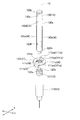
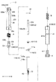
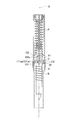
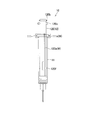
- FIG. 1 is a front view of the injection device according to the embodiment of the present invention, in which the housing is shown in cross section.
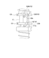
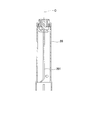
- FIG. 2 is a cross-sectional view of the housing according to the embodiment.
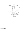
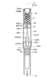
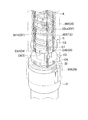
- FIG. 3 is an exploded perspective view of the syringe of the same embodiment.
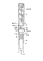
- FIG. 4 is a plan view of the syringe of the same embodiment.
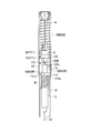
- FIG. 5 is a right side view of the syringe of the injection device of the same embodiment, and is a cross-sectional view of the barrel and the piston.
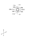
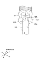
- FIG. 6 is a front view of the engaging member of the same embodiment.
- FIG. 7 is a bottom view of the engaging member.
- FIG. 8 is a cross-sectional view of the engaging member in the VIII-VIII direction.
- FIG. 9 is a front view showing a disassembled state of the injection device of the same embodiment, in which the housing and the cap are shown in cross section.
- FIG. 10 is an initial state of the injection device of the same embodiment, and is a front view showing a housing and a cap in cross section.
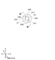
- FIG. 11 is a diagram showing a disengagement mechanism in the injection device in the initial state.
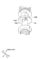
- FIG. 12 is a view showing a state in which the housing is a cross section and the injection needle is pulled out of the housing in the injection device of the same embodiment.
- FIG. 13 is a view showing a state in which the housing is a cross section and the rotary engaging portion and the rotating engaged portion are engaged in the injection device of the same embodiment.
- FIG. 10 is an initial state of the injection device of the same embodiment, and is a front view showing a housing and a cap in cross section.
- FIG. 11 is a diagram showing a disengagement mechanism in the injection device in the initial state.
- FIG. 12 is a view showing a
- FIG. 14 is a view showing a state in which the housing is a cross section and the plunger is rotated around the central axis in the injection device of the same embodiment.
- FIG. 15 is a diagram showing a disengagement mechanism in a state where the plunger is rotated around the central axis.
- FIG. 16 is a view showing the injection device of the same embodiment, in which the housing has a cross section and the injection needle is returned to the inside of the housing.
- FIG. 17 is a diagram showing a state in which the rotation prevention fitting portion and the rotation prevention fitting portion are fitted in a state where the injection needle is returned into the housing.
- FIG. 18 is a perspective view of an engaging member, a rod, and a cover portion according to a modified example of the injection device.
- FIG. 19 is a cross-sectional view of a plunger accommodating portion according to a modified example of the injection device.
- FIG. 20 is a cross-sectional view of the plunger accommodating portion according to the second embodiment of the injection device.
- FIG. 21 is a side view of the syringe according to the embodiment.
- FIG. 22 is a perspective view of the engaging member according to the embodiment.
- FIG. 23 is a front view of the injection device according to the same embodiment, showing a state in which the housing is a cross section and immediately before the rotationally engaged portion and the rotated engaged portion are disengaged.
- FIG. 24 is a detailed view showing a state immediately before the engagement between the rotationally engaged portion and the rotationally engaged portion is disengaged.
- FIG. 25 is a front view of the injection device according to the same embodiment, showing a state in which the housing is a cross section and the rotation engaging portion and the rotation engaged portion are disengaged.
- FIG. 26 is a detailed view showing a state in which the rotationally engaged portion and the rotationally engaged portion are disengaged.
- FIG. 27 is a front view of the injection device according to the same embodiment, showing a state in which the housing is a cross section and the engaging member is rotated around the central axis.
- FIG. 28 is a detailed view showing a state in which the engaging member is rotated around the central axis.
- FIG. 29 is a partially enlarged cross-sectional view of the syringe according to a modified example of the injection device.
- the injection device of the present embodiment is used, for example, when a patient administers a drug solution such as insulin or a remouch therapeutic agent to his / her body.
- the needle returns to the inside of the device.
- the injection device 1 of the present embodiment has a syringe 10 filled with a chemical solution in a housing 2 extending along the central axis O, and an engaging member engaged with the plunger 12 of the syringe 10.
- C, a plunger urging portion A engaged with the engaging member C, and a barrel urging portion B engaged with the barrel 11 of the syringe 10 are housed.
- O is the central axis
- the upper side in FIG. 1 is referred to as the "base end side”
- the lower side is referred to as the "tip side”.
- FIG. 1 is a front view of the injection device 1 of the present embodiment, in which the housing 2 is cut along the central axis O.
- the housing 2 is formed to accommodate the syringe 10.
- the housing 2 is formed in a tubular shape to cover the syringe 10.
- the housing 2 is formed in a cylindrical shape.
- the proximal end side is closed by the trigger portion 23, and the distal end side is formed in a tubular shape opened to project the injection needle 13 out of the device.
- the housing 2 has a partition portion 22 for partitioning the inside of the cylinder in the middle portion in the central axis O direction.
- a barrel accommodating portion 21 accommodating the barrel 11 is formed on one side of the housing 2 with respect to the partition portion 22.
- the barrel 11 is separated from the partition portion 22 by a predetermined distance from the partition portion 22 to one side from the first position in which the injection needle 13 is accommodated in the housing 2 (see FIGS. 1 and 10).
- the injection needle 13 can be moved between the second position and the second position in which the injection needle 13 protrudes from one side of the housing 2 (see FIG. 12).
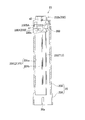
- a plunger accommodating portion 20 for accommodating the plunger 12 protruding from the base end side of the barrel 11 is formed on the other side of the housing 2 from the partition portion 22.
- the plunger accommodating portion 20 extends from the partition portion 22 toward the base end side of the central axis O. As shown in FIG. 1, the plunger accommodating portion 20 accommodates the plunger urging portion A, the engaging member C, and the plunger 12 in this order from the proximal end side to the distal end side.
- the plunger accommodating portion 20 includes an urging base portion 200 that abuts on the plunger urging portion A, which will be described later.
- the urging base portion 200 projects in the radial direction from the inner peripheral surface of the cylindrical plunger accommodating portion 20. Further, the urging base portion 200 is provided with an insertion hole 200b centered on the central axis O and communicating the inside and the outside of the plunger accommodating portion 20 along the central axis O. Therefore, the urging base portion 200 is formed in the shape of an inner collar in the plunger accommodating portion 20.
- the urging base portion 200 is provided with a tip-side projecting portion 200a that projects toward the tip end side in the central axis O direction and prevents the plunger urging portion A from moving in the radial direction.
- the tip side protrusion 200a is inserted into the plunger urging portion A, which will be described later.
- the plunger accommodating portion 20 includes an engaging holding mechanism Y1 that holds the engaging member C with respect to the plunger accommodating portion 20 so as not to rotate.
- the plunger accommodating portion 20 includes a holding convex portion 201 as the engaging holding mechanism Y1 on its inner peripheral surface.
- the holding convex portion 201 projects in the radial direction from the inner peripheral surface of the plunger accommodating portion 20.
- the holding convex portion 201 is continuously formed in the central axis O direction from the proximal end side to the distal end side of the plunger accommodating portion 20. Further, a plurality of the holding convex portions 201 are provided at intervals in the circumferential direction.
- the holding convex portion 201 includes a pair of first holding convex portions 201a that are concavely fitted to the first holding concave portion C40, which will be described later, and a pair of second holding convex portions that are concavely fitted to the second holding concave portion C41. It is equipped with a department.
- Each of the pair of first holding convex portions 201a and the pair of second holding convex portions are arranged so as to face each other in the radial direction on the inner peripheral surface of the substantially cylindrical plunger accommodating portion 20.
- the width of the first holding convex portion 201a in the circumferential direction is smaller than that of the second holding convex portion 201a.
- the engaging member C described later moves in the central axis O direction while being restricted from rotating around the central axis O.
- the plunger accommodating portion 20 has an enlarged diameter on the tip side both inside and outside the cylinder. The distal end side of the plunger accommodating portion 20 accommodates the partition portion 22 and the base end portion of the barrel accommodating portion 21.
- the plunger accommodating portion 20 is provided with a through hole 202 penetrating in the radial direction.
- the through hole 202 is provided along the peripheral surface of the cylindrical plunger accommodating portion 20 and at a position adjacent to the first holding convex portion 201a as shown in FIG.
- a pair of the through holes 202 of the present embodiment are provided so as to face each other in the radial direction.
- the plunger accommodating portion 20 is engaged with the engaging member C.
- the plunger urging unit 20 accommodates the plunger urging unit A that urges the plunger 12 from the start point to the end point.
- the starting point is a position on the tip side of the base end of the barrel 11 shown in FIG.
- the end point is the tip of the barrel 11.
- the plunger urging portion A of the present embodiment is composed of a compression coil spring wound around the central axis O.
- an engaging member C which will be described later, is inserted into the plunger urging portion A housed in the plunger accommodating portion 20.
- the housing 2 is provided with a barrel accommodating portion 21 on the tip end side of the central axis O with the partition portion 22 interposed therebetween.
- the barrel accommodating portion 21 is formed so as to be connected to the plunger accommodating portion 20 via the partition portion 22.
- the barrel accommodating portion 21 is formed in a tubular shape penetrating in the central axis O direction. Therefore, the plunger 12 inserted into the barrel 11 can be extended from the base end of the barrel accommodating portion 21 to the plunger accommodating portion 20, and the injection needle 13 can be projected from the tip of the barrel accommodating portion 21.
- the barrel accommodating portion 21 is formed in a stepped cylinder shape in which the inner diameter and outer diameter on the base end side are larger than the inner diameter and outer diameter on the tip end side. Therefore, the barrel accommodating portion 21 is formed on the front end side of the large cylinder side barrel accommodating portion 210 having a large inner diameter and outer diameter on the base end side and the large cylinder side barrel accommodating portion 210, and has an outer diameter and an outer diameter from the large cylinder side barrel accommodating portion 210.
- a small cylinder side barrel accommodating portion 211 having a small inner diameter is provided.
- the barrel side barrel accommodating portion 210 has a barrel receiving portion 210a for receiving the barrel 11 moved to the tip side by the urging of the plunger urging portion A and a cover portion 111 of the barrel 11 described later with respect to the barrel accommodating portion 21. It is provided with a rotation holding mechanism X that holds the rotation so as not to rotate.
- the barrel receiving portion 210a is located at a step portion where the base end of the small cylinder side barrel accommodating portion 211 and the tip end of the large cylinder side barrel accommodating portion 210 are continuous.
- the barrel receiving portion 210a is formed over the entire circumference of the barrel accommodating portion 21. Further, the rotation holding mechanism X is formed in the barrel side barrel accommodating portion 210.
- the rotation holding mechanism X of the present embodiment is continuously formed along the central axis O in the barrel side barrel accommodating portion 210 so as to extend from the partition portion 22 to the barrel receiving portion 210a.
- the rotation holding mechanism X of the present embodiment is formed as a holding convex portion 210b that is engaged with the holding concave portion 111b formed in the cover portion 111 of the barrel 11, which will be described later.
- the holding convex portion 210b projects inward of the barrel accommodating portion 21.
- a plurality of the holding convex portions 210b are provided at intervals in the circumferential direction.
- a pair of holding convex portions 210b are provided in a direction orthogonal to the central axis O.
- the barrel accommodating portion 21 includes an urging base portion 211a with which the barrel urging portion B is in contact. As shown in FIG. 1, the urging base portion 211a is projected from the cover portion 111 (barrel receiving portion 210a) to the tip side of the cover portion 111 (barrel receiving portion 210a) into the barrel accommodating portion 211 on the small cylinder side.
- the urging base portion 211a projects along the inner peripheral surface of the barrel accommodating portion 21. Further, the urging base portion 211a is formed in an inner collar shape along the inner surface of the barrel side barrel accommodating portion 211 so that the barrel 11 can be inserted.
- the partition portion 22 is configured to partition the inside of the housing 2.
- the partition portion 22 is located between the barrel accommodating portion 21 and the plunger accommodating portion 20.
- the partition portion 22 is a ring-shaped member.
- the partition portion 22 is configured to project inward in diameter from the inner surface of the barrel accommodating portion 210 on the large cylinder side of the barrel accommodating portion 21 and the inner surface of the plunger accommodating portion 20. Therefore, one surface of the partition portion 22 defines the tip end surface in the plunger accommodating portion 20, and the other surface defines the base end surface in the barrel accommodating portion 21.
- the partition portion 22 includes a through hole 220 for passing the plunger 12 through the barrel accommodating portion 21 and the plunger accommodating portion 20.
- the through hole 220 is formed smaller than the barrel accommodating portion 21 and the plunger accommodating portion 20.
- the partition portion 22 of the present embodiment is formed in the shape of an inner collar in the housing 2. Therefore, as shown in FIG. 1, the partition portion 22 can come into contact with the base end surface of the barrel 11 in the barrel accommodating portion 21. Therefore, the partition portion 22 regulates the movement of the barrel 11 on the base end side.
- the barrel urging portion B urges the barrel 11 from one side of the housing 2 toward the partition portion 22.
- the barrel urging portion B is arranged in the barrel accommodating portion 21.
- the barrel urging portion B of the present embodiment is composed of a compression coil spring wound around the central axis O. Specifically, as shown in FIG. 1, the barrel urging portion B is a coil spring through which the barrel 11 can be inserted. Further, the barrel urging portion B has one end side in contact with the barrel 11 and the other end side in contact with the urging base portion 211a in the central axis O direction. Specifically, one end side of the barrel urging portion B comes into contact with the front end side side surface of the cover portion 111 of the barrel 11.
- the barrel urging portion B urges the barrel 11 to the partition portion 22 (base end side).
- the urging force of the barrel urging portion B of the present embodiment is set to be weaker than the urging force of the plunger urging portion A.
- the injection device 1 of the present embodiment includes a trigger unit 23 configured to release the urging of the plunger urging unit A.
- the trigger portion 23 is in a state where the barrel 11 hits the partition portion 22 by the urging force of the barrel urging portion B, and the plunger 12 opposes the urging force of the plunger urging portion A and the tip of the plunger 12 is positioned at the starting point position. Can be locked so as not to release the urging of the plunger urging unit A. That is, the trigger portion 23 has an urging force holding position for holding the urging force of the plunger urging portion A so as not to be released. The trigger unit 23 releases the lock by a predetermined operation.
- the trigger unit 23 moves from the urging force holding position to the urging force release position by a predetermined operation.
- the trigger portion 23 includes a trigger mounting portion 230 provided at the base end of the plunger accommodating portion 20, a trigger main body portion 232 operated by the user, and the trigger main body portion 232 by the user. It includes a trigger lock operation unit 231 that locks the device so that it cannot be operated.
- the trigger mounting portion 230 is provided at the base end portion of the plunger accommodating portion 20.
- the trigger mounting portion 230 includes a base end portion 230A of the plunger accommodating portion 20 and a cylindrical portion 230B projecting from the base end portion 230A toward the base end side in the O direction of the central axis.
- An insertion hole 200b centered on the central axis O is formed in the base end portion 230A. Further, in the base end portion 230A, the side surface on the base end side thereof is a hooking portion 230a to which the trigger locking portion C5 of the engaging member C inserted into the insertion hole 200b is locked. In this embodiment, the base end portion 230A is also the urging base portion 200.
- the cylindrical portion 230B has a cylindrical shape formed around the central axis O.
- the cylindrical portion 230B includes a cylindrical body portion 230BA provided so as to surround the hook portion 230a, a lock step portion 230BB projecting inward from the inner surface of the cylindrical body portion 230BA, and an outer diameter portion from the outer surface of the cylindrical body portion 230BA. It is provided with a convex portion 230BC projecting in the direction.
- the lock step portion 230BB is a step portion that regulates the operation of the trigger main body portion 232.
- the lock step portion 230BB has a trigger main body portion 232 so that the trigger main body portion 232 (outer skirt portion 232b) cannot be pushed toward the tip side in the initial state (state before operation) shown in FIGS. The movement to the tip side is restricted.
- the convex portion 230BC guides the rotation operation of the trigger lock operation portion 231.
- a pair of the lock step portion 230BB and the convex portion 230BC are provided so as to face each other in the radial direction of the cylindrical body portion 230BA.
- the trigger main body 232 is pushed by the user of the injection device 1 from the proximal end side to the distal end side in the central axis O direction to activate the injection action by the injection device 1.
- the trigger body portion 232 includes a top plate portion 232a pressed by the operating user, an outer skirt portion 232b hanging from the outer peripheral edge of the top plate portion 232a toward the tip side, and a top plate portion 232a inside the outer skirt portion 232b.
- An inner skirt portion 232c hanging from the inner skirt portion 232c and a flat plate portion 232d hanging from the top plate portion 232a inside the inner skirt portion 232c are provided.
- the top plate portion 232a has a disk shape centered on the central axis O. The surface of the top plate portion 232a on the base end side is flat so that the user can easily press it.
- the outer skirt portion 232b is formed in a cylindrical shape formed over the entire circumference around the central axis O. As shown in FIG. 1, the outer skirt portion 232b is configured such that the tip portion abuts on the lock step portion 230BB of the trigger mounting portion 230. That is, the tip of the outer skirt portion 232b and the lock step portion 230BB form a lock mechanism portion V for locking the operation of the trigger portion 23.
- the outer skirt portion 232b is formed with a release groove 232ba released at the tip portion of the outer skirt portion 232b.
- the release groove 232ba is along the central axis O direction.
- the lock step portion 230BB can be inserted into the release groove 232ba. Therefore, when the positions of the release groove 232ba and the lock step portion 230BB in the circumferential direction match, the lock by the lock mechanism portion V is released as shown in FIG. Therefore, the trigger main body 232 can be pushed in.
- the outer skirt portion 232b is formed with an interlocking groove 230bb closed at the tip of the outer skirt portion 232b.
- the interlocking groove 230bb is along the central axis O direction.
- the interlocking convex portion 231ba of the trigger lock operation portion 231 is fitted into the interlocking groove 230bb.
- the inner skirt portion 232c is formed in a cylindrical shape formed over the entire circumference around the central axis O.
- the inner diameter of the inner skirt portion 232c substantially coincides with the inner diameter of the insertion hole 200b at the base end portion.
- the flat plate portion 232d has a length in the central axis O direction, and is formed in a plate shape having a width and a thickness in a direction orthogonal to the length.
- the flat plate portion 232d is longer than the outer skirt portion 232b and the inner skirt portion 232c. Further, the flat plate portion 232d has a width substantially equal to the width between the pair of trigger locking portions C5.
- the trigger lock operation unit 231 is a member that is operated to release the lock of the trigger unit 23 in the locked state. As shown in FIG. 2, the trigger lock operation portion 231 extends inward from the cylindrical main body portion 231a formed around the central axis O and the base end portion of the cylindrical main body portion 231a in the central axis O direction.
- the inner collar portion 231b is provided.
- the cylindrical body portion 231a is configured to rotatably surround the trigger mounting portion 230.
- a rotating groove 231aa extending along the circumferential direction is formed in the cylindrical body portion 231a.
- the rotating groove 231aa is formed so that the convex portion 230BC of the trigger mounting portion 230 can be fitted.
- the rotation angle of the trigger lock operation portion 231 is defined by abutting both ends of the rotation groove 231aa in the circumferential direction with the convex portion 230BC.
- the inner flange portion 231b is formed over the entire circumference of the cylindrical main body portion 231a.
- the inner flange portion 231b includes an interlocking convex portion 231ba projecting in the inward direction at the inner peripheral end portion.
- the interlocking convex portion 231ba is fitted into the interlocking groove 230bb.
- a plurality of interlocking convex portions 231ba are provided. As shown in FIG. 12, the interlocking convex portion 231ba also fits into the release groove 232ba.
- the trigger main body portion 232 is installed inside the trigger mounting portion 230.
- the trigger lock operation unit 231 is installed outside the trigger mounting unit 230 so as to interlock with the trigger main body unit 232.
- the tip of the outer skirt portion 232b of the trigger main body portion 232 is in contact with the lock step portion 230BB.
- the inner skirt portion 232c is separated from the hook portion 230a toward the base end side in the O direction of the central axis.
- the flat plate portion 232d is inserted between the pair of trigger locking portions C5 in a posture in which the width direction is along the opposite direction of the pair of trigger locking portions C5.
- the trigger main body portion is arranged with respect to the trigger mounting portion 230.
- the cylindrical body portion 231a surrounds the outside of the cylindrical body portion 230BA. Further, the convex portion 230BC is fitted in the rotating groove 231aa. Then, the interlocking convex portion 231ba is fitted into the interlocking groove 230bb and the release groove 232ba. In this way, the trigger lock operation unit 231 is arranged with respect to the trigger mounting unit 230.
- the trigger lock operation unit 231 is rotated, the trigger main body 232 rotates in conjunction with the rotation operation. Then, when the release groove 232ba rotates until it coincides with the lock step portion 230BB in the circumferential direction, the lock of the lock mechanism portion V is released.
- the lock of the lock mechanism portion V is the contact between the tip end portion of the outer skirt portion 232b and the lock step portion 230BB.
- the trigger main body 232 can be pushed in (see FIG. 12).
- the flat plate portion 232d has a thickness direction that matches the facing direction of the pair of trigger locking portions C5, and allows the pair of trigger locking portions C5 to bend inward in diameter.
- the inner skirt portion 232c (trigger activation portion) approaches the hook portion 230a. Then, the inner skirt portion 232c comes into contact with the trigger locking portion C5 that is locked to the hooking portion 230a, and the trigger locking portion C5 is bent inward in diameter. Therefore, the engagement between the hooking portion 230a and the trigger locking portion C5 is released. As a result, the injection action of the injection device 1 is activated.
- the syringe 10 has a barrel 11 provided with an injection needle 13 at the tip thereof and a barrel 11 capable of reciprocating between the barrel 11 with the base end side of the barrel 11 as the starting point and the injection needle 13 side as the ending point.
- a plunger 12 to be inserted inside is provided.
- the barrel 11 is housed in the barrel housing section 21.
- the barrel 11 is composed of a barrel main body 110 filled with a chemical solution and a cover portion 111 attached to the barrel main body 110.
- the barrel main body 110 of the present embodiment includes a cylindrical main body portion 110b and an outer flange portion 110a projecting from the base end portion of the main body portion 110b in the outer diameter direction.
- the cover portion 111 is attached to the barrel main body 110 so as to cover the outer collar portion 110a of the barrel main body 110.
- the cover portion 111 is formed in a tubular shape having a C-shaped bottom surface by cutting a part of the outer peripheral surface.
- the cover portion 111 of the present embodiment is formed to be larger than the outer collar of the barrel main body 110 in the radial direction. Therefore, the outer flange portion 110a of the barrel main body 110 is slid and inserted from the side surface of the cover portion 111 so that the C-shaped bottom surface holds the tubular barrel main body 110. As a result, the cover portion 111 is attached to the barrel main body 110.
- the cover portion 111 is formed with an insertion hole 111e for inserting the plunger 12 into the barrel 11.
- the insertion hole 111e is provided in a circular shape on the upper surface of the cover portion 111. Further, the insertion hole 111e is formed so as to be continuous with the opening of the tubular barrel body 110 when the cover portion 111 is attached to the barrel body 110.
- the insertion hole 111e of the present embodiment is formed larger than the rod 120 described later and smaller than the opening of the barrel body 110.
- the barrel 11 is provided with a rotary engaged portion 111a.
- the rotationally engaged portion 111a engages with the rotationally engaged portion 120d, which will be described later, when the plunger 12, which will be described later, moves from the start point to just before reaching the end point. Therefore, the rotation engaged portion 111a is configured to rotate the plunger 12 around the central axis O.
- the rotation engaged portion 111a is centered on an inclined surface 111aa that guides the plunger 12 to rotate around the central axis O, a horizontal plane 111ab extending in the horizontal direction from the inclined surface 111aa, and the horizontal plane 111ab.
- the inclined portion 111a has a vertical surface 111ac extending in the axis O direction.
- the inclined surface 111aa of the inclined portion 111a is arranged on the upper surface of the cover portion 111 attached to the barrel main body 110.
- the inclined surface 111aa is inclined so as to slide when the rotary engaging portion 120d is engaged.
- the inclined surface 111aa is a surface to which the rotating engaging portion 120d approaching from the base end side in the central axis O direction comes into contact.
- the inclined surface 111aa is a spiral inclined surface 111aa that wraps around the central axis O and is inclined toward the tip end side of the central axis O.
- the distance between the horizontal plane 111ab and the upper surface of the cover portion 111 is substantially equal to the distance between the tip end surface and the base end surface of the partition portion 22.
- the inclined portion 111a is formed around the circular insertion hole 111e formed in the cover portion 111. Further, the inclined portion 111a is formed so as to enter the through hole 220 of the partition portion 22 when the barrel 11 comes into contact with the partition portion 22.
- the inclined portion 111a functions as an engagement disengagement mechanism Z1 that disengages the plunger 12 and the engagement member C.
- a pair of inclined portions 111a are formed along the circular insertion hole 111e.
- the cover portion 111 includes a holding recess 111b as a rotation holding mechanism X that holds the rotary engaged portion 111a so as not to rotate with respect to the barrel accommodating portion 21. Further, the cover portion 111 includes a rotation regulating portion W that restricts the plunger 12 from rotating around the central axis O up to a predetermined distance in the central axis O direction when the plunger 12 is inserted into the barrel 11.
- the cover portion 111 includes an axial movement groove portion 111c as a rotation restricting portion W.
- the holding recess 111b is formed in a direction along the central axis O on the outer peripheral surface of the cover portion 111 formed in a circular shape in a plan view. Further, in the present embodiment, a pair of holding recesses 111b are formed in the X direction shown in FIG. 4 in the radial direction of the cover portion 111 orthogonal to the central axis O direction.
- the axial movement groove portion 111c is formed so as to cut out the inner peripheral surface of the insertion hole 111e in the central axis O direction, and the axial movement protrusion 120e of the rod 120 described later is inserted. .. Further, in the present embodiment, the cover portion 111 is formed with two axial movement groove portions 111c.
- the plunger 12 is engaged with a piston 121 (not shown in FIG. 1) that reciprocates between a start point and an end point in a liquid-tight contact state in the barrel 11.
- the rod 120 and the rod 120 are provided.
- the piston 121 is arranged so as to seal the inside of the barrel 11 as shown in FIGS. 3 and 5.
- the piston 121 is engaged with a rod 120, which will be described later.
- the piston 121 has a connecting hole 121a into which the tip protrusion 120h of the rod 120 is inserted, and a spiral annular protrusion formed in the connecting hole 121a along the peripheral surface. It includes 121b.
- the piston 121 is larger than the insertion hole 111e provided in the cover portion 111, there is no possibility that the piston 121 will fall out of the barrel 11.
- the rod 120 is formed so as to extend in the housing 2 along the central axis O.
- One side (tip side) of the rod 120 in the central axis O direction is engaged with the piston 121 (not shown in FIG. 1) in the barrel 11, and the other side (base end side) is engaged with the engaging member C.
- the rod 120 includes a rod body 120a extending in the central axis O direction, a pin portion 120b provided on the rod body 120a, and a first branch portion 120c engaged with the engaging member C.
- a second branch portion 120d for rotating the plunger 12 an axial movement protrusion 120e for preventing the plunger 12 from rotating around the central axis O, and a retaining portion 120f for preventing the plunger 12 from coming off the barrel 11.
- the rod body 120a is formed in a columnar shape.
- the rod body 120a is formed to have substantially the same size as the insertion hole 111e formed in the cover portion 111 in the radial direction. Further, in the present embodiment, when the plunger 12 is inserted to the end point, the rod body 120a is the barrel body of the barrel 11 in the central axis O direction so that the base end side of the plunger 12 extends out of the barrel 11. It is formed longer than 110.
- the pin portion 120b provided on the rod body 120a engages the plunger 12 and the engaging member C. Specifically, in the injection device 1 shown in FIG. 1, the pin portion 120b is inserted into a release hole C30 (not shown in FIG. 1) of the engaging member C. Further, the pin portion 120b is arranged at a position that does not coincide with the release hole C30 in the circumferential direction. As a result, the plunger 12 is prevented from coming off from the engaging member C, and the engagement between the engaging member C and the plunger 12 is maintained.
- the pin portion 120b is formed so as to project from the base end of the rod body 120a in a direction orthogonal to the central axis O (specifically, the X direction). ..
- the pin portion 120b functions as a rotation prevention fitting portion 120b that fits with the rotation prevention fitting portion C20 described later. Further, when the plunger 12 is inserted into the barrel 11 to form the syringe 10, the pin portions 120b are arranged in pairs so as to face each other in the X direction as shown in FIGS. 4 and 5.
- the first branch portion 120c protrudes from the outer peripheral surface of the columnar rod body 120a.
- the first branch portion 120c is provided on the base end side of the rod body 120a in the central axis O direction. Further, the first branch portion 120c is arranged on the tip end side of the pin portion 120b.
- the first branch portion 120c is attached to the engaging member C.
- the urging engaging portion C3 is brought into contact with the pin portion 120b so as to be sandwiched between them. As a result, the plunger 12 engages with the engaging member C.
- the first branch portion 120c of the present embodiment functions as the urged engaged portion 120c that engages with the urging engaging portion C3. Further, as shown in FIG. 1, the first branch portion 120c is located on the bottom surface side (tip side) of the engaging member C, and restricts the plunger 12 from moving to the engaging member C side. In this embodiment, a pair of first branch portions 120c are provided in the X direction as shown in FIGS. 4 and 5.
- the second branch portion 120d is provided on the tip side of the first branch portion 120c in the central axis O direction.
- the second branch portion 120d is a rotary engaging portion 120d provided on the plunger 12.
- the second branch portion 120d functions as an engagement disengagement mechanism Z1 that disengages the plunger 12 and the engagement member C.
- the second branch portion 120d is provided on the cover portion 111 when the plunger 12 moves from a position (start point) on the tip side of the base end of the barrel 11 to just before reaching the tip end (end point) of the barrel 11.
- Engage with the inclined portion (rotationally engaged portion) 111a Engage with the inclined portion (rotationally engaged portion) 111a.
- the rod 120 is rotated around the central axis O.
- the second branch portion 120d is arranged so as to face the inclined portion 111a in the central axis O direction. Further, the second branch portion 120d of the present embodiment is formed in a circular protrusion shape so as to easily rotate along the inclined portion 111a. Further, as shown in FIGS. 4 and 5, a pair of the second branch portions 120d are provided in the X direction.
- the shaft moving protrusion 120e functions as a rotation regulating portion W that regulates the plunger 12 inserted in the barrel 11 so as not to rotate around the central axis O.
- the shaft moving protrusion 120e is inserted into the barrel 11 along the shaft moving groove 111c provided in the cover portion 111.
- the rod 120 is restricted from rotating in the circumferential direction and is allowed to move in the central axis O direction.
- the shaft moving protrusion 120e protrudes from the outer peripheral surface of the rod body 120a.
- the axial moving protrusion 12e extends from the tip of the rod body 120a toward the proximal end side, and extends from the second branch portion 120d to a position on the distal end side.
- the axial movement protrusion 120e extends continuously to the tip of the rod body 120a with a predetermined distance from the second branch 120d on the tip side.
- the shaft moving protrusion 120e fits into the shaft moving groove portion 111c as shown in FIG.
- a pair of axially moving protrusions 120e are provided in the Y direction.
- the retaining portion 120f functions to prevent the rod 120 inserted in the barrel body 110 from coming off the barrel body 110.
- the retaining portion 120f is formed so as to project from the outer peripheral surface of the rod body 120a.
- the protruding width of the retaining portion 120f is smaller than that of the second branch portion 120d.
- the retaining portion 120f projects in a tapered shape in which the projecting width increases from the tip end side to the base end side.
- the base end side surface of the retaining portion 120f is a surface orthogonal to the central axis O. Therefore, it is easy to insert the plunger 12 into the barrel 11.
- the retaining portion 120f is provided on the tip side of the rod main body 120a with respect to the second branch portion 120d.
- the retaining portion 120f is arranged between the tip end and the base end of the shaft moving protrusion 120e. Therefore, as shown in FIG. 3, when the rod body 120a is inserted into the cover portion 111 so that the shaft movement protrusion 120e as the rotation restricting portion W is along the shaft movement groove portion 111c of the cover portion 111, FIG. As shown in the above, the retaining portion 120f gets over the insertion hole 111e formed in the cover portion 111 and is inserted into the barrel 11. When a force for pulling out the rod 120 from the barrel 11 acts, the side surface of the base end of the retaining portion 120f and the bottom surface of the cover portion 111 come into contact with each other to prevent the rod 120 from coming off.
- the barrel 11 when the cap K described later is removed from the housing 2, the barrel 11 also advances toward the tip side due to the close contact between the needle cap K2 and the barrel 11. However, the contact between the retaining portion 120f and the cover portion 111 prevents the barrel 11 from advancing.
- a pair of retaining portions 120f are provided in the X direction.
- the tip protrusion 120h engages the rod 120 with the piston 121.
- the tip protrusion 120h projects from the tip of the rod body 120a toward the tip side in the central axis O direction. Further, the tip protrusion 120h is formed smaller than the rod body 120a so that it can be inserted into the connecting hole 121a of the piston 121.
- the tip protrusion 120h is inserted into the connecting hole 121a of the piston 121 as shown in FIG.
- the engaging member C is arranged in the plunger accommodating portion 20 and is engaged with the plunger 12.
- the engaging member C includes an engaging body C1 formed in a tubular shape, a trigger locking portion C5 locked to a trigger portion 23 provided in the housing 2, and the plunger. It includes an urging receiving portion C2 that receives urging by the urging portion A, and an urging engaging portion C3 formed on one side (tip side) of the urging receiving portion C2 in the central axis O direction.
- the engaging body C1 is formed in a tubular shape for inserting the rod 120 when the engagement between the plunger 12 and the engaging member C is released.
- the engaging body C1 is formed in a tubular shape larger than the rod 120.
- the engaging body C1 is provided with an opening passage C11 that penetrates the engaging member C in the radial direction. As shown in FIG. 6, the opening passage C11 is provided between the urging receiving portion C2 and the urging engaging portion C3. Specifically, the opening passage C11 is provided so as to cut out between the urging receiving portion C2 and the urging engaging portion C3.
- the trigger locking portion C5 protrudes from the other side (base end side) of the engaging body C1 in the central axis O direction.
- the trigger locking portion C5 of the present embodiment is formed in a bifurcated shape as shown in FIG.
- a tapered rib C50 that increases outward as it progresses from the protruding tip to the protruding base end is formed.
- the urging receiving portion C2 is formed so as to project from the outer peripheral surface of the engaging main body C1.
- the urging receiving portion C2 is in contact with the other end of the plunger urging portion A. Therefore, the engaging member C approaches the urging base portion 200 on the proximal end side of the central axis O, thereby compressing the plunger urging portion A.
- the urging receiving portion C2 of the present embodiment is formed in the shape of an outer collar protruding outward from the engaging body C1 (in the present embodiment, a round outer collar shape).
- the urging receiving portion C2 is formed to have substantially the same size as the inner diameter of the tubular plunger accommodating portion 20 in the radial direction.
- the engaging member C is formed with an urging engaging portion C3 that engages with the plunger 12 at the tip of the urging receiving portion C2 in the central axis O direction.
- the urging engaging portion C3 has an outer collar shape that protrudes in the radial direction from the outer peripheral surface of the engaging main body C1. In the present embodiment, the urging engaging portion C3 has a round outer collar shape.
- the engaging member C is provided with a release hole C30 and a rotation prevention fitting portion C20 to be fitted with the rotation prevention fitting portion 120b.
- the release hole C30 is formed so as to penetrate the urging engaging portion C3 in the central axis O direction.
- the release hole C30 is formed so as to be continuous with the opening passage C11 in the circumferential direction.
- the release hole C30 is formed larger than the pin portion 120b and the first branch portion 120c. Therefore, the pin portion 120b can be passed through the release hole C30, and the base end portion of the rod 120 can be inserted into the engaging member C.
- two release holes C30 of the present embodiment are formed at positions facing each other in the radial direction.
- the release hole C30 is formed in a direction different from that of the holding recess C4 described later in the radial direction. Specifically, the release hole C30 is formed in a direction different from that of the first holding recess C40.
- the rotation prevention fitted portion C20 is provided inside the urging receiving portion C2 of the engaging member C. Specifically, as shown in FIG. 8, the rotation prevention fitted portion C20 is provided on the proximal end side in the central axis O direction from the urging receiving portion C2. Further, the rotation prevention fitting portion C20 of the present embodiment is formed as a pin hole portion C20 into which a pin portion 120b provided at the base end of the rod 120 is inserted. Two pin hole portions C20 of the present embodiment are provided in the engaging member C. The rotation prevention fitted portion C20 is closer to the base end side in the central axis O direction than the release hole C30, but the position in the radial direction coincides with the release hole C30 as shown in FIG. That is, the rotation prevention fitted portion C20 and the release hole C30 communicate with each other in the central axis O direction.
- the engaging member C is formed with an engaging holding mechanism Y1 that holds the engaging member C with respect to the plunger accommodating portion 20 so as not to rotate.
- the engaging member C is provided with a holding recess C4 that functions as an engaging holding mechanism Y1 in the urging receiving portion C2 and the urging engaging portion C3. ..
- the holding recess C4 is unevenly fitted to the holding convex portion 201 of the plunger accommodating portion 20.
- four holding recesses C4 are provided in the substantially cylindrical engaging member C at intervals of 90 °.
- the holding recess C4 includes a pair of first holding recesses C40 formed so as to face the A direction shown in FIG. 7, and a pair of second holding recesses C41 formed so as to face the B direction. ..
- the width of the first holding recess C40 is smaller than that of the second holding recess C41 in the circumferential direction.
- the pair of first holding recesses C40 are unevenly fitted to the pair of first holding protrusions 201a.
- the pair of second holding recesses C41 are unevenly fitted to the pair of second holding protrusions.
- the plunger accommodating portion 20, the plunger urging portion A, the engaging member C, the partition portion 22, and the rod are assembled in the direction of the central axis O.
- the 120, the syringe 10, the barrel urging portion B, the barrel accommodating portion 21, and the cap K are arranged.
- the piston 121 is inserted into the barrel body 110 filled with the chemical solution so as to be located at the starting point.
- a prefilled syringe with the cover portion 111 attached to the barrel body 110 is used.
- the cap K is configured to cover the tip end portion of the barrel accommodating portion 21, and protects the injection needle 13 accommodated in the barrel accommodating portion 21. Then, after accommodating the plunger urging portion A in the plunger accommodating portion 20 along the central axis O direction, the engaging member C is inserted into the plunger accommodating portion 20. Here, the holding concave portion C4 of the engaging member C is inserted so as to fit into the holding convex portion 201 in the plunger accommodating portion 20. At this time, the trigger lock operation portion 231 and the trigger main body portion 232 are rotated around the central axis O with respect to the trigger mounting portion 230. As a result, the lock mechanism unit V is unlocked. In the present embodiment, as shown in FIG.
- the first holding recess C40 is arranged so as to face the front surface, and the engaging member C is advanced into the plunger accommodating portion 20.
- an engaging holding mechanism Y1 that holds the engaging member C with respect to the plunger accommodating portion 20 so as not to rotate around the central axis O is formed.
- one end of the engaging member C is urged while resisting the urging of the plunger urging portion A by the urging receiving portion C2 of the engaging member C.
- the other end side of the plunger urging portion A engaged with the base portion 200 is advanced to the base end side of the plunger accommodating portion 20.
- the trigger locking portion C5 is inserted into the insertion hole 200b defined by the urging base portion 200. Then, the rib C50 of the trigger locking portion C5 is hooked on the hooking portion 230a, and the engaging member C is fixed to the trigger portion 23. As a result, the urging of the compressed plunger urging unit A is held so as not to be released. Therefore, the trigger portion 23 is in the urging holding position. After that, the trigger lock operation unit 231 and the trigger main body unit 232 are rotated, and the operation of the trigger unit 23 is locked by the lock mechanism unit V. After that, the rod 120 is engaged with the engaging member C housed in the plunger accommodating portion 20. Specifically, as shown in FIG.
- the direction of the release hole C30 provided in the urging engaging portion C3 and the direction in which the pin portion 120b is formed are made to coincide with each other.
- the rod 120 is inserted into the engaging body C1 so that the pin portion 120b is inserted into the release hole C30.
- the rod 120 or the engaging body C1 is rotated around the central axis O so that the direction of the release hole C30 and the X direction are different as shown in FIG.
- the urging engaging portion C3 is arranged between the pin portion 120b and the first branch portion 120c.
- the rod 120 and the engaging member C are engaged with each other. In this engaged state, the engaging member C and the rod 120 are engaged so as to move in conjunction with the central axis O direction. Further, the engaging member C and the rod 120 are in a state of being relatively rotatable around the central axis O.
- the barrel urging portion B is stored in the barrel accommodating portion 21 so that the other end of the barrel urging portion B abuts on the urging base portion 211a.
- the syringe 10 is inserted into the barrel accommodating portion 21.
- the holding recess 111b of the cover portion 111 attached to the barrel body 110 of the syringe 10 fits into the holding convex portion 210b of the barrel accommodating portion 21.
- the rotation engaged portion (inclined portion) 111a of the cover portion 111 is held with respect to the barrel accommodating portion 21 so as not to rotate around the central axis O.
- the holding mechanism X is formed. Further, after the partition portion 22 is attached to the base end of the barrel accommodating portion 21, the partition portion 22 is provided so as to extend in the central axis O direction on the outer peripheral surface of the barrel accommodating portion 21 on the proximal end side, and the diameter of the barrel accommodating portion 21.
- a pair of outer peripheral surface protrusions (not shown) facing each other in the direction extends from the tip of the plunger accommodating portion 20 toward the proximal end side and penetrates the peripheral surface of the plunger accommodating portion 20 in the radial direction of the plunger accommodating portion 20. Fits into a pair of axial notches 20a facing each other.
- the barrel accommodating portion 210 on the large cylinder side is inserted into the plunger accommodating portion 20, and the barrel accommodating portion 21 and the plunger accommodating portion 20 are engaged with each other.
- the barrel 11 is in contact with the partition portion 22 due to the urging of the barrel urging portion B.
- the injection needle 13 on the distal end side is accommodated in the barrel accommodating portion 21, and the barrel 11 is in the first position.
- the rod 120 accommodated in the plunger accommodating portion 20 is inserted into the barrel 11.
- the shaft moving protrusion 120e and the shaft moving groove 111c are fitted to form a rotation regulating portion W that regulates the plunger 12 from rotating around the central axis O with respect to the barrel 11.
- the second branch portion 120d as the rotation engaging portion 120d of the plunger 12 and the rotation engaged portion 111a of the barrel 11 are aligned in the central axis O direction.
- the second branch portion 120d and the rotation engaged portion 111a are arranged so as to overlap each other in the X direction.
- the plunger 12 moves in the central axis O direction while being restricted by the rotation regulating portion W. Then, when the plunger 12 reaches just before reaching the tip of the barrel 11, the second branch portion 120d of the plunger 12 comes into contact with the inclined portion 111a of the barrel 11. That is, the rotation restricting portion W positions the engaging position between the second branch portion 120d (rotation engaging portion 120d) of the plunger 12 and the inclined portion 111a (rotation engaged portion 111a) of the barrel 11.
- the cap K closes the tip of the housing 2 and protects the injection needle 13 in the housing 2 from external factors.
- the cap K of the present embodiment is formed larger than the housing 2 and formed in a cylindrical shape so that the housing 2 can be inserted into the inside.
- the cap K includes a needle cap holding portion K1 that is inserted into the housing 2 and is externally attached to the injection needle 13.
- the needle cap holding portion K1 is externally attached to the injection needle 13 by fitting the needle cap K2 attached to the barrel 11. In this way, the syringe 10 is inserted into the housing 2 to assemble the injection device 1 in the initial state as shown in FIG.
- FIG. 10 shows the initial state of the injection device 1 of the present embodiment.
- a cap K is attached to the tip of the housing 2. Therefore, when using the injection device 1 of the present embodiment, first, the cap K is removed from the housing 2. As a result, as shown in FIG. 1, an opening is formed at the tip of the housing 2. At this time, the needle cap K2 at the tip of the barrel 11 is removed together with the cap K in a state of being fitted to the needle cap holding portion K1.
- the injection needle 13 housed in the housing 2 is projected from the opening at the tip of the housing 2.
- the injection needle 13 in the injection device 1 with the cap K removed, the injection needle 13 is housed in the housing 2, and the barrel 11 is in the first position. Therefore, the lock of the trigger portion 23 is released, and the trigger portion 23 is pushed toward the plunger accommodating portion 20 side.
- the trigger lock operation portion 231 and the trigger main body portion 232 are rotated around the central axis O with respect to the trigger mounting portion 230.
- the release groove 232ba of the trigger body portion 232 and the lock step portion 230BB of the trigger mounting portion 230 are aligned to unlock the trigger portion 23.
- the flat plate portion 232d is rotated from the state shown in FIG. 10 so that the thickness of the flat plate portion 232d matches the facing direction of the pair of trigger locking portions C5.
- the trigger main body 232 is pushed toward the tip end side in the central axis O direction.
- the inner skirt portion 232c as the trigger starting portion comes into contact with the inclined surface of the tip of the trigger locking portion C5 of the engaging member C that is locked to the hooking portion 230a.
- the inner skirt portion 232c comes into contact with the rib C50.
- the trigger locking portion C5 which is allowed to bend inward due to the rotation of the flat plate portion 232d, bends in the inward direction, and the engagement between the trigger locking portion C5 and the hooking portion 230a is released. Therefore, as shown in FIG. 12, the engagement between the trigger portion 23 and the engaging member C is released. Therefore, the urging of the plunger urging unit A held in the compressed state is released. Therefore, the trigger unit 23 moves from the urging holding position for holding the urging force of the plunger urging unit A so as not to be released to the urging force releasing position for releasing the urging force of the plunger urging unit A.
- the barrel urging portion B is set to have a weaker urging force than the plunger urging portion A. Therefore, as the engaging member C advances toward the tip end side of the plunger accommodating portion 20, the barrel urging portion B is pushed by the bottom surface of the cover portion 111 and compressed. Further, in the cover portion 111, the holding concave portion 111b moves in the central axis O direction along the holding convex portion 210b provided in the barrel side barrel accommodating portion 210.
- the cover portion 111 moves until the bottom surface abuts on the barrel receiving portion 210a. Therefore, as shown in FIG. 12, the barrel urging portion B is compressed until the bottom surface of the cover portion 111 comes into contact with the barrel receiving portion 210a. Further, as the barrel 11 moves toward the tip end side of the barrel accommodating portion 21, the injection needle 13 provided at the tip end of the barrel main body 110 protrudes from the barrel accommodating portion 21. Therefore, the barrel 11 in the first position moves to the second position.
- the engaging member C and the syringe 10 move, the engaging member C is restricted from rotating around the central axis O by the engaging holding mechanism Y1. Further, the rotation-engaged portion 111a is restricted from rotating around the central axis O by the rotation holding mechanism X.
- the plunger 12 is restricted from rotating around the central axis O by the rotation regulating unit W. Therefore, it is possible to prevent the engaging member C and the plunger 12 from being accidentally disengaged. Further, it is possible to prevent the engaging positions of the rotating engaging portion 120d and the rotating engaged portion 111a from being displaced from each other.
- the plunger 12 advances in the barrel 11.
- the engaging member C moves toward the tip end side of the plunger accommodating portion 20 so that the holding recess C4 is along the holding convex portion 201 provided in the plunger accommodating portion 20.
- the axial moving protrusion 120e moves along the axial moving groove 111c provided in the cover 111.
- the engaging member C is restricted from rotating around the central axis O by the engaging holding mechanism Y1.
- the rotation engaging portion 111a of the barrel 11 is restricted from rotating around the central axis O by the rotation holding mechanism X.
- the plunger 12 (rotation engaging portion 120d) is restricted from rotating around the central axis O by the rotation regulating portion W.
- the piston 121 engaged with the rod 120 advances in the barrel body 110. Therefore, the piston 121 pushes the chemical solution out of the barrel from the injection needle 13.
- the axial movement protrusion 120e extending from the tip end of the rod body 120a to the tip end side from the second branch portion 120d comes out from the axial movement groove portion 111c to the tip end side. Therefore, the regulation by the rotation regulation unit W is released. That is, the plunger 12 (rotationally engaged portion 120d) can rotate around the central axis O with respect to the rotation engaged portion 111a of the barrel 11. Then, as shown in FIG. 13, the second branch portion 120d as the rotationally engaged portion comes into contact with the inclined portion 111a as the rotationally engaged portion, and the disengagement mechanism Z1 operates.
- the plunger 12 barrels from the position (start point) on the tip end side of the barrel 11 to the tip end (end point) of the barrel 11. Move within 11. Then, after the plunger 12 reaches immediately before the tip of the barrel 11, the second branch portion 120d slides along the inclined portion 111a (specifically, the inclined surface 111aa). Therefore, as shown in FIG. 13, from the state where the second branch portion 120d and the inclined portion 111a (specifically, the inclined surface 111aa) are in contact with each other, the second branch portion 120d is the inclined portion as shown in FIG. The 111a changes to a sliding state.
- the engaging member C is restricted from rotating by the engaging holding mechanism Y1
- the rotation engaged portion 111a is restricted from rotating by the rotation holding mechanism X.
- the regulation of the rotation regulation unit W that regulates the rotation of the plunger 12 has been lifted. Therefore, the plunger 12 and the engaging member C rotate relative to each other around the central axis O. Specifically, in the present embodiment, the plunger 12 rotates about the central axis O with respect to the engaging member C. Further, the rotary engaging portion 120d of the plunger 12 rotates around the central axis O with respect to the rotating engaged portion 111a.
- the rotary engaging portion 120d rotates about 30 ° to the left in a state of being engaged with the inclined surface 111aa of the inclined portion 111a shown in FIG. Therefore, the rotary engaging portion 120d moves to the upper surface side of the cover portion 111 shown in FIG.
- the rotation of the plunger 12 also rotates the pin portion 120b and the first branch portion 120c.
- the pin portion 120b and the first branch portion 120c are arranged in the X direction. Therefore, as shown in FIG. 15, when the first branch portion 120c is arranged at a position coincide with the release hole C30 in the circumferential direction by the rotation of the plunger 12, the pin portion 120b also coincides with the release hole C30 in the circumferential direction. It is placed at the position that matches with. Therefore, when the disengagement mechanism Z1 is activated, the engagement between the urged engaging portion C3 and the urged engaged portion 120c is released. As a result, the plunger 12 and the engaging member C are disengaged. At this time, the plunger 12 has reached the end point.
- the plunger urging portion A pushes only the engaging member C toward the tip end side.
- the barrel urging portion B compressed by the plunger urging portion A is released. Therefore, the barrel urging portion B pushes the syringe 10 toward the proximal end side. Therefore, as shown in FIG. 16, the engaging member C moves to a position where the urging engaging portion C3 is close to the partition portion 22 in a state where the rotation is restricted by the engaging holding mechanism Y1, and is attached at this position. The force is fixed.
- the barrel 11 (specifically, the cover portion 111) moves to a position close to the partition portion 22 in a state where the rotation engaged portion 111a is restricted from rotating by the rotation holding mechanism X. Then, the barrel 11 is biased and fixed at this position.
- one end side of the barrel urging portion B is in contact with the bottom surface of the cover portion 111. Therefore, the urging of the barrel urging portion B pushes the cover portion 111 toward the partition portion 22.
- the inclined portion 111a enters the through hole 220 of the partition portion 22.
- the plunger 12 moves to the base end side of the housing 2 together with the barrel 11. Therefore, the first branch portion 120c inserts the release hole C30 of the engaging member C, and as shown in FIG. 17, the pin portion 120b is fitted into the rotation prevention fitted portion C20. Therefore, the plunger 12 is prevented from rotating in the reverse direction by fitting the rotation prevention fitting portion (pin portion) 120b and the rotation prevention fitting portion C20. As a result, the reverse rotation prevention mechanism Y2 that prevents the plunger 12 from rotating in the opposite direction (reverse rotation) to the rotation when the plunger 12 disengages from the engaging member C functions.
- the urging engaged portion (first branch portion) 120c is located between the urging engaging portion C3 and the urging receiving portion C2 that are close to the partition portion 22.
- the syringe 10 is urged and fixed on the proximal end side of the engaging member C with respect to the urging engaging portion C3 by the urging of the barrel urging portion B toward the proximal end side.
- the urging engaging portion C3 of the engaging member C is urged and fixed on the tip side of the urging engaged portion 120c by the urging of the plunger urging portion A toward the tip end side. In this way, the state in which the engaging member C and the plunger 12 are disengaged is maintained.
- the plunger 12 moves to the base end side of the housing 2, the first branch portion 120c inserts the release hole C30 of the engaging member C, and the pin portion 120b is the rotation prevention fitting portion. Fitted in C20.
- the first branch portion 120c is arranged at the same position as the through hole 202 provided in the circumferential direction of the plunger accommodating portion 20 in the central axis O direction and the circumferential direction. Therefore, the first branch portion 120c that can be seen from the outside of the housing 2 through the through hole 202 and inside the housing 2 functions as an indicator that the drug administration is completed.
- the first branch portion 120c has a color different from that of other members, for example, the rod body 120a. This makes it possible to more reliably indicate that the drug administration has been completed.
- the above is the description of how to use the injection device 1 of the present embodiment.
- the injection device 1 of the present embodiment is inserted into the barrel 11 so as to be reciprocally movable between the barrel 11 provided with the injection needle 13 at the tip and the proximal end side of the barrel 11 as the end point.
- a syringe 10 including a plunger 12 and a tubular housing 2 for accommodating the syringe 10, wherein an injection needle 13 is accommodated in the housing on one side in the central axis O direction.
- Barrel accommodating the barrel 11 so as to be movable between the first position and the second position in which the injection needle 13 protrudes from one side of the housing 2 at a predetermined distance from the first position to one side.
- a housing 2 in which a portion 21 is formed and a plunger accommodating portion 20 for accommodating a plunger 12 protruding from the base end side of the barrel 11 is formed on the other side of the barrel accommodating portion 21, and arranged in the barrel accommodating portion 21.
- the barrel urging portion B for urging the barrel 11 from one side of the housing 2 to the other side in which the injection needle 13 is accommodated in the housing 2 and the plunger accommodating portion 20 are arranged.
- the engaging member C that engages with the plunger 12, the plunger urging portion A that engages with the engaging member C and urges the plunger 12 from the start point to the end point, and the barrel 11 is the barrel.
- the plunger 12 is provided with a trigger unit 23 configured to move to, and as the trigger unit 23 moves to the urging force release position, the plunger 12 is moved from the starting point by the urging force of the plunger urging unit A.
- the plunger 12 and the engaging member C are disengaged and the plunger 12 is positioned at the end point. It is characterized by including an engagement disengagement mechanism Z1 for causing the injection.
- the urging of the plunger urging portion A causes the syringe 10 to move to the central axis.
- the injection needle 13 moves to one side in the O direction until it protrudes from the housing 2.
- the urging force of the barrel urging portion B keeps the barrel 11 in position against the urging of the plunger urging portion A, whereas the plunger is held in position.
- the 12 is subsequently moved to one side in the central axis O direction by the urging of the plunger urging portion A and pushed against the barrel 11, and the chemical solution in the barrel 11 is poured out. Then, when the plunger 12 moves to the end point, the pouring is completed.
- the engagement between the plunger 12 and the engagement member C which the disengagement mechanism Z1 has moved toward the end point, is disengaged by relatively rotating both of them.
- the plunger urging portion A releases the urging of the plunger 12 to the plunger 12.
- the syringe 10 is urged to the other side in the central axis O direction by the urging of the barrel urging portion B, whereby the injection needle 13 is pulled into the housing 2.
- the disengagement mechanism Z1 engages with the plunger 12 that has moved from the start point to the end point by relatively rotating the plunger 12 and the engagement member C. It is configured to disengage from the member C. Therefore, at the end point of the movement of the plunger 12, the engagement between the plunger 12 and the engaging member C is released, so that the plunger urging unit A is released from urging the plunger 12. Then, the syringe 10 is pushed to the other side in the central axis O direction by the urging of the barrel urging portion B. As a result, the injection needle 13 can be pulled into the housing 2.
- the disengagement mechanism includes a rotary engaging portion provided on the plunger and a rotary engaged portion provided on the barrel, and the plunger is said to be described from the starting point.
- the plunger rotates around the central axis and is configured to disengage the plunger from the engaging member.
- the engagement position between the rotating engaging portion 120d and the rotating engaged portion 111a can be set according to the moving position of the plunger 12 with respect to the barrel 11, so that the plunger 12 can be moved. It can be disengaged according to the end point. Specifically, when the plunger 12 moves from the position on the tip end side of the barrel 11 to just before reaching the tip end of the barrel 11, the second branch portion 120d engages with the inclined portion 111a, and the second branch portion 120d is engaged with the inclined portion 111a. The branch portion 120d slides along the inclined portion 111a. As a result, the plunger 12 rotates around the central axis, and as shown in FIG.
- the pin portion 120b and the first branch portion 120c are arranged at positions that coincide with the release hole C30 in the circumferential direction, and the plunger 12 and the engaging member are engaged with each other.
- the engagement with C is released.
- the barrel urging portion B pushes the cover portion 111 toward the partition portion 22. Therefore, as shown in FIG. 16, the plunger 12 is housed in the engaging member C, and the barrel 11 moves to the partition portion 22 side. Therefore, the injection needle 13 can be pulled inside the housing 2.
- the plunger 12 is inserted into the engaging member C. Therefore, after the engagement between the plunger 12 and the engaging member C is disengaged, the urging engaged portion 120c is between the urging engaging portion C3 and the urging receiving portion C2 which are close to the partition portion 22.
- the bias is fixed. Therefore, since it is possible to prevent the urging engaging portion C3 and the urging engaged portion 120c from returning to the engaged state, it is possible to prevent the injection needle 13 once housed from accidentally protruding again.
- the disengagement mechanism Z1 includes a rotary engagement portion 120d provided on the plunger 12 and a rotary engagement portion 111a provided on the barrel 11.
- the rotary engaging portion 120d and the rotationally engaged portion 111a engage with each other, so that the plunger 12 rotates around the central axis O and the plunger 12 is rotated. It is configured to release the engagement between the 12 and the engaging member C. Therefore, since the engagement position between the rotary engaging portion 120d and the rotary engaged portion 111a can be set according to the moving position of the plunger 12 with respect to the barrel 11, the engagement is disengaged immediately before the end point of the movement of the plunger 12. Can be done.
- the injection device 1 of the present embodiment includes a rotation holding mechanism X that holds the rotation engaged portion 111a with respect to the barrel accommodating portion 21 so as not to rotate. Then, the injection device 1 includes a reverse rotation preventing means Y that holds the plunger 12 that has been disengaged from the engaging member C by operating the disengagement mechanism Z1 so as not to rotate in the reverse direction. Therefore, after the rotary engaging portion 120d and the rotary engaged portion 111a are engaged with each other to rotate the plunger 12 and disengage the engagement member C, the plunger 12 rotates in the reverse direction, and again. It is possible to prevent the engagement state.
- the reverse rotation prevention means Y has an engagement holding mechanism Y1 that holds the engaging member C with respect to the plunger accommodating portion 20 so as not to rotate, and an engagement holding mechanism Y1 after disengagement.
- a reverse rotation prevention mechanism Y2 that holds the plunger 12 so as not to reverse rotation with respect to the engaging member C is provided. Therefore, after preventing the rotation engaged portion 111a and the engaging member C from rotating, the reverse rotation of the plunger 12 after the disengagement is prevented, so that the reverse rotation is surely prevented and the engaged state is re-engaged. Can be effectively prevented.
- the reverse rotation prevention mechanism Y2 is provided in the rotation prevention fitting portion 120b provided at the other end of the plunger 12 and the urging receiving portion C2 of the engaging member C.
- the anti-rotation fitted portion C20 is included, and the engaging engaging portion C3 and the biased engaged portion 120c are disengaged by the disengagement mechanism Z1, and the engaging member C is close to the partition portion 22.
- the anti-rotation fitting portion 120b and the anti-rotation mating portion C20 are fitted to each other in a state where the urged engaged portion 120c is located between the urging engaging portion C3 and the urging receiving portion C2. Therefore, it is configured to prevent the plunger 12 from rotating in the reverse direction.
- the rotation engaged portion 111a of the barrel 11 is prevented from rotating by the rotation holding mechanism X, and the engaging member C is prevented from rotating by the engagement holding mechanism Y1.
- the urging engaged portion 120c is located between the urging engaging portion C3 and the urging receiving portion C2 of the engaging member C.
- the rotation prevention fitting portion 120b and the rotation prevention fitting portion C20 are fitted to prevent the plunger 12 from rotating in the reverse direction. Therefore, it is possible to reliably hold the state in which the plunger and the engaging member C are disengaged and prevent the injection needle 13 from protruding again.
- the engagement between the plunger 12 and the engaging member C is disengaged by relatively rotating both of them, so that the injection needle can be reliably returned.
- the injection device is not limited to the above embodiment, and it goes without saying that various modifications can be made without departing from the gist of the present invention.
- other configurations can be added to the configurations of the above embodiments.
- a part of the configuration of the above embodiment can be replaced with another configuration.
- a part of the configuration of the above embodiment can be deleted.
- the engaging member C may be rotated, or both the plunger 12 and the engaging member C may be rotated in opposite directions.
- the engaging member C may be provided with a rotating engaging portion, and the barrel or the housing may be provided with a rotating engaged portion.
- the urging engaging portion of the engaging member C is provided with a holding convex portion C4 as a rotational engaging portion, and as shown in FIG. 19, the plunger accommodating portion 20 is provided with a rotating engaged portion.
- the holding recess 201 may be provided.
- the holding recess 201 provided in the plunger accommodating portion 20 is provided so as to rotate the engaging member C.
- the holding recess 201 extending from the proximal end to the distal end side along the central axis O direction has the distal end side of the central axis O in the circumferential direction and is inclined toward the distal end.
- the engaging member C can be rotated when the holding convex portion C4 of the engaging member C passes through the holding recess 201 on the tip side that is inclined.
- the plunger urging portion may be formed of a torsion spring.
- the engaging member C is moved to the tip end of the plunger accommodating portion by the urging. Move to the side. Then, the holding convex portion C4 of the engaging member C is passed through the inclined holding concave portion 201 on the tip side by utilizing the rotation around the central axis O of the plunger urging portion formed of the torsion spring. In this way, the engaging member C may be rotated.
- the tip end side of the holding recess 201 may be a horizontal groove.
- the injection device of the second embodiment configured to rotate the engaging member by utilizing the rotation around the central axis of the plunger urging portion will be described.
- the same reference numerals are used for the same configurations as those of the first embodiment, and the description is not repeated for the portion overlapping with the first embodiment. The points different from the form will be described.
- the plunger accommodating portion 20 of the second embodiment includes a tip accommodating portion 20A and an accommodating main body portion 20B arranged on the proximal end side of the tip accommodating portion 20A.
- the plunger accommodating portion 20 of the second embodiment is not formed with a through hole 202 penetrating in the radial direction.
- the tip accommodating portion 20A accommodates the base end portion and the partition portion 22 of the barrel accommodating portion 21.
- the tip accommodating portion 20A is arranged on the distal end side of the plunger accommodating portion 20. Further, the tip accommodating portion 20A is formed in a tubular shape (specifically, a cylindrical shape). As shown in FIG. 20, the tip accommodating portion 20A is provided with an axial notch portion 20a that is continuous from the tip to the proximal end side and penetrates the peripheral surface. A pair of axial cut portions 20a of the second embodiment are provided so as to face each other in the radial direction.
- the accommodating main body portion 20B accommodates the plunger urging portion A and the engaging member C.
- the accommodating main body 20B is formed in a tubular shape (specifically, a cylindrical shape).
- the accommodating main body portion 20B is continuously provided at the base end of the tip accommodating portion 20A. Therefore, the accommodating main body portion 20B is arranged on the proximal end side of the plunger accommodating portion 20 with respect to the tip accommodating portion 20A. Further, the accommodating main body portion 20B is formed longer than the tip accommodating portion 20A in the direction of the central axis. Further, the accommodating main body portion 20B of the second embodiment has an inner diameter and an outer diameter smaller than those of the tip accommodating portion 20A.
- the plunger accommodating portion 20 is formed so that the inner diameter and the outer diameter on the distal end side are larger than those on the proximal end side. Further, in the plunger accommodating portion 20, the tip of the accommodating main body portion 20B is provided as a step of the inner diameter difference between the tip accommodating portion 20A and the accommodating main body portion 20B.
- An urging base 200 is provided on the base end side of the accommodation main body 20B. As shown in FIG. 20, the urging base portion 200 of the second embodiment is provided with an urging mounting portion 200c for mounting one end of the plunger urging portion A housed in the accommodating main body portion 20B. ..
- the urging mounting portion 200c of the second embodiment is formed as an insertion hole 200c that penetrates the urging base portion 200 in the central axis direction so as to insert one end of the plunger urging portion A.
- the plunger accommodating portion 20 serves as an engaging holding mechanism Y1 for holding the engaging member C with respect to the plunger accommodating portion 20 so as to hold the holding convex portion 201 (specifically, the first holding convex portion 201a and the second holding portion 201a).
- the convex portion 201b) is provided.
- the holding convex portion 201 is formed in the accommodating main body portion 20B.
- the holding convex portion 201 is continuously formed from the base end to the tip end side of the accommodating main body portion 20B. Therefore, when the holding convex portion 201 is fitted with the holding concave portion C4 described later, the holding convex portion 201 guides the engaging member C in the plunger accommodating portion 20 in the central axis direction. Further, by fitting the holding convex portion 201 into the holding concave portion C4, the rotation of the engaging member C is restricted, and the rotation by the plunger urging portion A is restricted.
- the tip of the holding convex portion 201 of the second embodiment is provided in the plunger accommodating portion 20 on the proximal end side of the tip of the accommodating main body portion 20B formed as a step. Therefore, in the accommodating main body portion 20B, the distal end side of the holding convex portion 201 is formed as a flat surface. Further, in the second embodiment, the distance from the tip of the holding convex portion 201 to the tip of the accommodating main body portion 20B is equal to the distance between the urging receiving portion C2 of the engaging member C and the urging engaging portion C3. In the second embodiment, as shown in FIG. 20, the tips of the first holding convex portion 201a and the second holding convex portion 201b are arranged at the same position in the central axis direction.
- the plunger accommodating portion 20 of the second embodiment includes an engagement disengagement mechanism Z1 that disengages the plunger 12 from the engagement member C.
- the plunger accommodating portion 20 of the second embodiment includes a rotary engaged portion 201 as the disengaging mechanism Z1.
- the accommodating main body portion 20B includes a rotary engaged portion 201.
- the holding convex portion 201 functions as the rotation engaged portion 201.
- the plunger accommodating portion 20 includes a rotation permitting mechanism T that allows relative rotation of the plunger accommodating portion 20 and the engaging member C around the central axis.
- the accommodating main body portion 20B of the second embodiment includes an accommodating convex portion 203 as a rotation allowance mechanism T. As shown in FIG. 20, the accommodating convex portion 203 continuously extends from the base end to the tip end of the accommodating main body portion 20B. Therefore, the accommodating convex portion 203 is arranged on the tip side of the accommodating convex portion 201 in the accommodating main body portion 20B.
- a pair of accommodating convex portions 203 of the second embodiment are formed in the tubular accommodating main body portion 20B so as to face each other in the radial direction. Further, the accommodating convex portion 203 is arranged between the first holding convex portion 201a and the second holding convex portion 201b.
- the accommodating main body 20B includes a rotation stop mechanism U that stops the rotation of the plunger 12 and the engaging member C around the central axis.
- the accommodating main body portion 20B of the second embodiment includes an engaging stopped portion 203 as a rotation stop mechanism U.
- the engagement-stopped portion 203 is configured as a housing convex portion 203 that protrudes in the radial direction in the housing main body portion 20B.
- the configurations of the trigger mounting portion 230 and the trigger main body portion 232 are different from those of the first embodiment.
- the urging mounting portion 200c for mounting one end of the plunger urging portion A to the base end portion 230A (specifically, insertion). Hole 200c) is formed.
- the cylindrical body portion 230BA of the second embodiment is formed with a guide portion a1 that communicates with the urging mounting portion 200c.
- the guide portion a1 is formed so as to dent the inside of the cylindrical body portion 230BA so that one end of the plunger urging portion A inserted into the insertion hole 200c is aligned.
- the trigger body portion 232 of the second embodiment is formed with a guide portion a2 on which one end of the plunger urging portion A is aligned with the outer skirt portion 232b.
- the guide portion a2 is formed so that the outer circumference of the outer skirt portion 232b is recessed.
- the other guide portion a2 is formed continuously from the distal end side to the proximal end side of the outer skirt portion 232b.
- the other guide portion a2 when the trigger portion 23 is unlocked, the other guide portion a2 has the same arrangement in the circumferential direction as the one guide portion a1 and communicates with each other in the central axis direction. Then, by pushing the trigger main body 232, the other guide portion a2 overlaps with the one guide portion a1.
- the plunger urging portion A of the second embodiment is configured as a torsion spring that expands and contracts in the central axis direction and accumulates a force (circumferential urging force) that rotates around the central axis.
- the plunger urging portion A constitutes the disengagement mechanism Z1. Therefore, the disengagement mechanism Z1 rotates the engaging member C around the central axis by utilizing the circumferential urging force of the plunger urging portion A.
- One end of the plunger urging portion A is attached to the urging mounting portion 200c provided in the plunger accommodating portion 20 shown in FIG. Further, the other end of the plunger urging portion A is attached to the urging mounting portion C7 provided on the engaging member C shown in FIG. 22.
- the plunger urging portion A extends from the compressed state to move the engaging member C. Further, the plunger urging portion A configured as a torsion spring is configured to rotate the engaging member C around the central axis by the circumferential urging force due to the torsion. Therefore, the plunger urging portion A is configured to urge the engaging member C in a direction in which the engaging member C is rotated around the central axis.
- the plunger urging portion A of the second embodiment rotates when the holding convex portion 201 and the holding concave portion C4 are released from the fitting and the rotation restriction by the engagement holding mechanism Y1 is released.
- the syringe 10 of the second embodiment is different from the first embodiment in that it does not include the disengagement mechanism Z1.
- the rod 120 is not provided with the second branch portion 120d as the rotation engaging portion.
- the cover portion 111 is not provided with a rotation engaged portion. Therefore, the upper surface of the cover portion 111 of the second embodiment is formed as a flat surface.
- the axial moving protrusion 120e of the second embodiment is formed longer on the base end side of the rod 120 than that of the first embodiment. That is, as shown in FIG. 21, when the plunger 12 inserted in the barrel 11 reaches the tip end (end point) of the barrel 11, the axial movement protrusion 120e of the second embodiment moves the cover portion 111 by axis. The length is set so that it will not come out of the groove 111c. Therefore, in the second embodiment, rotation of the rod 120 around the central axis is prevented.
- the engaging member C of the second embodiment is provided with an urging mounting portion C7 for mounting the other end of the plunger urging portion A.
- an insertion hole C7 for inserting the other end of the plunger urging portion A is formed in the urging receiving portion C2. Therefore, in the second embodiment, the engaging member C can rotate around the central axis by the circumferential urging force of the plunger urging portion A.
- the urging mounting portion C7 of the second embodiment is located between the holding recess (specifically, the first holding recess C40) and the engaging recess C6 in the circumferential direction of the outer flange-shaped urging receiving portion C2. It is provided.
- the engaging member C and the plunger urging portion A are accommodated in the plunger accommodating portion 20, one end of the plunger urging portion A is attached to the urging attachment portion 200c, and the plunger urging portion A is attached. The other end of A is inserted into the insertion hole C7. Then, the engaging member C advances toward the proximal end side of the plunger accommodating portion 20 with torque applied to the plunger urging portion A, so that the plunger urging portion A is compressed.
- the engaging member C of the second embodiment includes a holding recess C4 as an engaging holding mechanism Y1.
- the holding recess C4 fits into the holding convex portion 201 when the engaging member C is accommodated in the plunger accommodating portion 20.
- the holding recess C4 is formed so that the peripheral surfaces of the urging receiving portion C2 and the urging engaging portion C3 are recessed.
- the holding recess C4 is formed as a recess width that can be fitted with the holding convex portion 201. Therefore, when the engaging member C is accommodated in the plunger accommodating portion 20, the holding concave portion C4 fits into the holding convex portion 201, so that the engaging member C is restricted from rotating in the central axis direction.
- the engaging member C moves in the direction of the central axis while keeping the holding concave portion C4 along the holding convex portion 201. As a result, the engaging member C is guided in the direction of the central axis in the plunger accommodating portion 20.
- the engaging member C of the second embodiment includes a rotating engaging portion C4 as an engaging disengaging mechanism Z1.
- the engaging member C of the second embodiment is formed with a holding recess C4 as a rotating engaging portion C4 in the urging receiving portion C2 and the urging engaging portion C3. ..
- the rotary engaging portion C4 engages with the rotating engaged portion 201.
- the holding convex portion 201 of the second embodiment is provided on the proximal end side of the accommodating main body portion 20B. Therefore, the tip side of the holding convex portion 201 is formed as a flat surface.
- the distance between the urging receiving portion C2 and the urging engaging portion C3 is equal to or smaller than the distance from the tip of the holding convex portion 201 to the accommodating main body portion 20B. Therefore, when the engaging member C moves in the plunger accommodating portion 20 and the holding recess C4 is arranged on the tip side of the tip of the holding convex portion 201, the rotary engaging portion C4 and the rotating engaged portion 201 Is disengaged.
- the engaging member C of the second embodiment includes a rotation permitting mechanism T that allows relative rotation of the plunger accommodating portion 20 and the engaging member C around the central axis.
- the engaging member C of the second embodiment includes an engaging recess C6 as a rotation allowing mechanism T.
- the engaging recess C6 is provided so as to be recessed on the peripheral surfaces of the urging receiving portion C2 and the urging engaging portion C3. Further, the engaging recess C6 is formed larger in the width direction than the accommodating convex portion 203. Therefore, in the second embodiment, when the engaging member C is accommodated in the plunger accommodating portion 20, the engaging concave portion C6 fits (freely fits) the accommodating convex portion 203.
- the engaging concave portion C6 and the accommodating convex portion 203 move relative to each other around the central axis, so that the plunger accommodating portion 20 and the engaging member C rotate relative to each other around the central axis.
- the engaging recess C6 moves around the central axis by the circumferential urging force of the plunger urging portion A. Therefore, the engaging member C rotates around the central axis.
- the engaging recess C6 of the second embodiment is the first holding recess C40 and the second holding recess C41 among the peripheral surfaces of the urging receiving portion C2 and the urging engaging portion C3 having a circular shape when viewed in the direction of the central axis. It is provided between. Further, the engaging recess C6 is provided with two engaging recesses C6 in each of the urging receiving portion C2 and the urging engaging portion C3.
- the engaging member C of the second embodiment includes a rotation stopping mechanism U that stops the rotation of the plunger 12 and the engaging member C around the central axis.
- the engaging member C includes an engaging stop portion C60 as a rotation stop mechanism U.
- the engagement stop portion C60 of the second embodiment is provided on the circumferential edge of the engagement recess C6 provided so as to be recessed on the peripheral surfaces of the urging receiving portion C2 and the urging engaging portion C3. Therefore, when the engaging recess C6 and the accommodating convex portion 203 move relatively around the central axis, the engaging stopping portion C60 comes into contact with the accommodating convex portion 203, so that the plunger accommodating portion 20 and the engaging member C are engaged. Stops rotation around the central axis of.
- the other guide portion a2 provided on the trigger main body portion 232 is arranged in the circumferential direction on the other hand guide portion a1 provided on the cylindrical body portion 230BA. Matches with.
- the other guide portion a2 communicates with the one guide portion a1 in the direction of the central axis. Then, by pushing the trigger main body portion 232, the other guide portion a2 overlaps with the other guide portion a2. Therefore, the engagement between the trigger portion 23 and the engaging member C is released.
- the trigger unit 23 moves from the urging force holding position for holding the urging force of the plunger urging unit A so as not to be released to the urging force opening position for releasing the urging force of the plunger urging unit A. .. Then, when the plunger urging portion A is urged, the urging receiving portion C2 is pushed, and the engaging member C and the syringe 10 move to the tip end side of the plunger accommodating portion 20.
- one end of the plunger urging portion A of the second embodiment is attached to the urging attachment portion 200c formed in the plunger accommodating portion 20. Further, the other end of the plunger urging portion A is attached to the urging mounting portion C7 provided on the engaging member C. Then, in a state where the engaging member C is accommodated on the proximal end side of the plunger accommodating portion 20, the engaging holding mechanism Y1 is formed by fitting the holding concave portion C4 and the holding convex portion 201. Therefore, the engagement holding mechanism Y1 regulates the engagement member C from rotating around the central axis with respect to the plunger accommodating portion 20.
- the engagement holding mechanism Y1 of the second embodiment maintains the circumferential urging force of the plunger urging portion A by restricting the rotation of the engaging member C. Therefore, the plunger urging portion A whose other end is attached to the engaging member C extends toward the tip end side in the central axis direction without rotating around the central axis in a state of being released from compression, and the engaging member C And push the syringe 10 toward the tip side. Therefore, the engaging member C advances toward the tip end side along the central axis direction until the fitting of the holding convex portion 201 and the holding concave portion C4 is released. In the second embodiment, the engaging concave portion C6 and the accommodating convex portion 203 are fitted.
- the cover portion 111 moves in the central axis direction while compressing the barrel urging portion B until the bottom surface abuts on the barrel receiving portion 210a.
- the holding recess 111b of the cover portion 111 moves along the holding convex portion of the barrel accommodating portion 21 as in the first embodiment. Therefore, the barrel 11 moves toward the tip end side in the central axis direction without rotating around the central axis. After that, as shown in FIG. 23, the barrel 11 moves from the first position to the second position, and the injection needle 13 protrudes from the barrel accommodating portion 21.
- the axial moving protrusion 120e of the second embodiment has a length that does not come off from the axial moving groove portion 111c of the cover portion 111 when the plunger 12 reaches the tip of the barrel 11. It is set. Therefore, in the second embodiment, even if the plunger 12 reaches the tip of the barrel 11, the shaft moving protrusion 120e does not come out of the shaft moving groove 111c, so that the regulation by the rotation regulating portion W is not released. Therefore, in the second embodiment, the plunger 12 that has moved in the direction of the central axis does not rotate around the central axis.
- the engaging member C advances in the accommodating main body portion 20B while the holding concave portion C4 is along the holding convex portion 201.
- the engaging member C moves from the proximal end side to the distal end side of the plunger accommodating portion 20 by extending the plunger urging portion A.
- the engaging recess C6 is along the accommodating convex portion 203.
- the fitting between the holding convex portion 201 and the holding concave portion C4 is released.
- the fitting of the holding concave portion C4 provided in the urging engaging portion C3 and the holding convex portion 201 of the plunger accommodating portion 20 is released. ..
- the holding recess C4 provided in the urging receiving portion C2 is along the holding convex portion 201, while the engaging member C is moved along the central axis direction of the plunger accommodating portion 20. Move to the tip side.
- the engaging member C in the state shown in FIG. 23 moves toward the tip end side of the plunger accommodating portion 20 along the central axis direction. Then, the engaging member C in the state shown in FIG. 25 is biased and fixed when the biasing engaging portion C3 moves to a position where the biasing engaging portion C3 is close to the partition portion 22. At this time, as shown in FIG. 26, the fitting of the holding concave portion C4 formed in the urging receiving portion C2 and the holding convex portion 201 is released. Therefore, the regulation by the engagement holding mechanism Y1 that holds the engaging member C with respect to the plunger accommodating portion 20 so as not to rotate is released. In the second embodiment, the plunger 12 reaches the end point (the tip of the barrel 11) when the urging engaging portion C3 moves to a position close to the partition portion 22.
- the plunger accommodating portion 20 and the engaging member C include a rotation permitting mechanism T.
- the accommodating main body portion 20B includes an accommodating convex portion 203
- the engaging member C includes an engaging concave portion C6. Then, in the second embodiment, the engaging concave portion C6 and the accommodating convex portion 203 are fitted (freely fitted).
- the rotation of the engaging member C around the central axis is stopped by the rotation stop mechanism U.
- the engaging member C rotates around the central axis to accommodate the engaging stop portion C60 provided at the circumferential edge of the engaging recess C6. It abuts on the convex portion 203.
- the rotation of the engaging member C around the central axis is stopped.
- the holding convex portion 201 and the holding concave portion C4 are different in the circumferential direction. It is placed in position. Therefore, the engaging member C is fixed so as not to move to the proximal end side of the plunger accommodating portion 20.
- the release hole C30 also rotates due to the rotation of the engaging member C.
- the engaging stop portion C60 and the accommodating convex portion 203 come into contact with each other and the rotation of the engaging member C around the central axis is stopped, as shown in FIGS. It is arranged at a position that coincides with the one branch portion 120c and the pin portion 120b in the circumferential direction. Therefore, the engagement between the urging engaging portion C3 and the urging engaged portion 120c is released, and the engagement between the plunger 12 and the engaging member C is released.
- the disengagement mechanism Z1 of the second embodiment is engaged by the circumferential urging force of the plunger urging portion A when the engagement between the rotationally engaged portion 201 and the rotational engagement portion C4 is disengaged.
- the plunger 12 and the engaging member C are disengaged.
- the plunger urging portion A is configured to urge the engaging member C in the direction in which the engaging member C rotates around the central axis.
- the engagement releasing mechanism Z1 causes the engaging member C to rotate around the central axis with respect to the plunger 12 by the circumferential urging force of the plunger urging portion A, whereby the plunger 12 and the engaging member C are brought into contact with each other. It is configured to disengage. Therefore, when the engaging member C rotates around the central axis, the plunger 12 and the engaging member C are disengaged, so that, for example, the plunger urging portion A attaches to the plunger 12. The force is released. Therefore, the syringe 10 is urged to the other side in the central axis direction by the urging of the barrel urging portion B, whereby the injection needle 13 can be pulled into the housing.
- the plunger urging portion A is a torsion spring, and is configured to rotate the engaging member C by the circumferential urging force of the torsion spring. Therefore, according to the configuration, the engaging member C is rotated by the circumferential urging force of the plunger urging portion A, which is a torsion spring, to engage the plunger 12 with the engaging member C. It can be released.
- the disengagement mechanism Z1 includes a rotary engaging portion C4 provided on the engaging member C and a rotating engaged portion 201 provided on the plunger accommodating portion 20, and the rotary engaging portion
- the joint portion C4 and the rotation engaged portion 201 are engaged, the plunger 12 moves from the start point to the end point, and the rotation engagement portion C4 and the rotation engagement portion 201 are engaged with each other.
- the plunger 12 and the engaging member C rotate relative to each other around the central axis, and the plunger 12 and the engaging member C are disengaged.
- the position for disengaging the rotationally engaged portion C4 and the rotationally engaged portion 201 can be set according to the moving position of the plunger 12 with respect to the barrel 11, so that, for example, the movement of the plunger 12 can be set.
- the engagement between the rotary engaging portion C4 and the rotary engaged portion 201 can be disengaged according to the end point.
- the holding convex portion 201 and the holding concave portion C4 are fitted, the plunger 12 moves from the start point to the end point, and the fitting between the holding convex portion 201 and the holding concave portion C4 is released.
- the engaging member C rotates relative to the central axis, and the plunger 12 and the engaging member C are disengaged from each other. Therefore, when the plunger 12 reaches the end point (the tip of the barrel 11), the engaging member C can rotate relative to the plunger 12.
- the engaging member C when the plunger 12 moves to the end point, the engaging member C is rotated around the central axis by disengaging the holding concave portion C4 and the holding convex portion 201. It is configured to disengage the plunger 12 from the engaging member C. According to the configuration, for example, when the plunger 12 moves to the tip of the barrel 11 as a terminal, the chemical solution in the barrel 11 is released by disengaging the holding recess C4 and the holding protrusion 201. When the injection is completed, the syringe 10 is urged to the other side in the central axis direction by the urging of the barrel urging portion B, and the injection needle 13 can be pulled into the housing 2.
- the injection device 1 of the second embodiment includes a rotation stop mechanism U that stops the relative rotation of the plunger 12 and the engagement member C around the central axis, and the rotation stop mechanism U is attached to the engagement member C.
- the plunger is provided by engaging the engagement stop portion C60 and the engagement stop portion 203, including the engagement stop portion C60 provided and the engagement stop portion 203 provided in the plunger accommodating portion 20.
- the relative rotation of 12 and the engaging member C around the central axis is stopped. Therefore, by stopping the relative rotation of the plunger 12 and the engaging member C around the central axis, the plunger 12 and the engaging member C continue to rotate relative to the central axis in the plunger accommodating portion 20. Can be prevented.
- the holding convex portion 201 and the holding concave portion C4 are different in the circumferential direction. Placed in position. Therefore, in the second embodiment, it is possible to prevent the engaging member C after rotating around the central axis from moving to the proximal end side of the plunger urging portion A.
- the rotary engaging portion is the holding recess C4 and the rotating engaged portion is the holding convex portion 201 has been described.
- the present invention is not limited to this, and for example, the rotary engaging portion may be the holding convex portion 201, and the rotating engaged portion may be the holding concave portion C4.
- the present invention is not limited to this, and the plunger 12 may be rotated, or both the plunger 12 and the engaging member C may be rotated in opposite directions.
- the present invention is not limited to this, for example, as shown in FIG. 29, by forming a male screw or a female screw as a screw 121b on the piston and forming a female screw or a male screw as a screw 120h on the rod and screwing them together.
- the piston 121 and the rod 120 can also be connected.
- the disengagement mechanism is configured to rotate the rod, the direction of rotation of the rod can also be set to the direction in which the screw is loosened.
- the rotation direction of the rod 120 may be the direction in which the screw is tightened.
- the tip of the rod 120 may be configured to push the piston 121 into the barrel 11 by contacting the end surface of the piston 121.
- the rod 120 can be configured not to have a tip protrusion 120h at its tip.
- the piston 121 may be configured not to include the connecting hole 121a.
- the present invention is not limited to this, and the barrel 11 may be configured so as not to come into contact with the partition portion 22. Further, the partition portion 22 may not be provided.
- the barrel urging portion B and the plunger urging portion A are not limited to springs, but may be rubber.
- the urging receiving portion C2 and the urging engaging portion C3 of the engaging member C are separately provided, but the urging engaging portion C3 can also be used as the urging receiving portion C2.
- the first branch portion 120c and the second branch portion 120d are formed in a columnar shape, but may have other shapes.
- the first branch portion 120c may be a fan-shaped plate centered on a prism or the central axis O. When a fan-shaped plate is used, it is preferable that the release hole C30 is also a fan-shaped hole.
- the second branch portion 120d may be an inclined surface corresponding to the inclined surface 111aa of the inclined portion 111a. Further, the rib shape extending in the central axis O direction in which the first branch portion 120c and the second branch portion 120d are connected may be formed.
- the start point may be the base end of the barrel (the base end of the main body 110b), or the end point may be closer to the base end than the tip of the barrel. That is, as long as the start point is on the base end side of the barrel and the end point is on the tip end side, the start point may be set to the base end portion of the barrel and the end point may be set to other than the tip end portion of the barrel.
- the relative rotation between the plunger and the engaging member is not limited to the case where the relative rotation between the plunger and the engaging member operates immediately before the end point as in the first embodiment, and the plunger and the engaging member may rotate relative to each other from the beginning of the movement of the plunger. That is, by rotating the plunger and the engaging member relative to each other around the central axis, the engagement between the plunger and the engaging member is released, and the position where the movement from the start point of the plunger stops is the end point.
- the trigger portion is configured to release the urging of the plunger urging portion by pushing the trigger portion.
- the predetermined operation of releasing the holding of the urging by the plunger urging portion may be, for example, an operation of pulling the trigger portion in the direction of the central axis or an operation of rotating the trigger portion around the central axis. That is, the trigger portion is configured to move to an urging force holding position that does not release the urging force of the plunger urging portion and an urging force opening position that releases the urging force of the plunger urging portion from the urging force holding position. It suffices if it is done.
- Trigger body part 232a ... Top plate part, 232b ... Outer skirt part, 232ba ... Release groove, 232c ... Inner skirt part, 232d ... Flat plate part, A ... Plunger Biasing part, B ... Barrel urging part, C ... Engaging member, C1 ... Engaging body, C11 ... Opening passage, C2 ... Bias receiving part, C20 ... Anti-rotation mating part, C3 ... Biasing engagement Part, C30 ... Release hole, C4 ... Holding concave part, C4 ... Holding convex part, C40 ... First holding concave part, C41 ... Second holding concave part, C5 ... Trigger locking part, C50 ...
Landscapes
- Health & Medical Sciences (AREA)
- Engineering & Computer Science (AREA)
- Hematology (AREA)
- Anesthesiology (AREA)
- Biomedical Technology (AREA)
- Heart & Thoracic Surgery (AREA)
- Vascular Medicine (AREA)
- Life Sciences & Earth Sciences (AREA)
- Animal Behavior & Ethology (AREA)
- General Health & Medical Sciences (AREA)
- Public Health (AREA)
- Veterinary Medicine (AREA)
- Environmental & Geological Engineering (AREA)
- Infusion, Injection, And Reservoir Apparatuses (AREA)
- Fuel-Injection Apparatus (AREA)
Abstract
Priority Applications (6)
| Application Number | Priority Date | Filing Date | Title |
|---|---|---|---|
| KR1020227020720A KR20220140482A (ko) | 2020-02-14 | 2021-02-12 | 주사 장치 |
| US17/798,487 US20230076297A1 (en) | 2020-02-14 | 2021-02-12 | Injection device |
| CA3167233A CA3167233A1 (fr) | 2020-02-14 | 2021-02-12 | Dispositif d'injection |
| CN202180013470.XA CN115087476A (zh) | 2020-02-14 | 2021-02-12 | 注射装置 |
| JP2022500468A JPWO2021162086A1 (fr) | 2020-02-14 | 2021-02-12 | |
| EP21753333.0A EP4104882A4 (fr) | 2020-02-14 | 2021-02-12 | Dispositif d'injection |
Applications Claiming Priority (2)
| Application Number | Priority Date | Filing Date | Title |
|---|---|---|---|
| JP2020023484 | 2020-02-14 | ||
| JP2020-023484 | 2020-02-14 |
Publications (1)
| Publication Number | Publication Date |
|---|---|
| WO2021162086A1 true WO2021162086A1 (fr) | 2021-08-19 |
Family
ID=77291753
Family Applications (1)
| Application Number | Title | Priority Date | Filing Date |
|---|---|---|---|
| PCT/JP2021/005229 WO2021162086A1 (fr) | 2020-02-14 | 2021-02-12 | Dispositif d'injection |
Country Status (8)
| Country | Link |
|---|---|
| US (1) | US20230076297A1 (fr) |
| EP (1) | EP4104882A4 (fr) |
| JP (1) | JPWO2021162086A1 (fr) |
| KR (1) | KR20220140482A (fr) |
| CN (1) | CN115087476A (fr) |
| CA (1) | CA3167233A1 (fr) |
| TW (1) | TW202135876A (fr) |
| WO (1) | WO2021162086A1 (fr) |
Citations (6)
| Publication number | Priority date | Publication date | Assignee | Title |
|---|---|---|---|---|
| JP3292747B2 (ja) | 1991-05-30 | 2002-06-17 | オーエン マムフォード リミテッド | 注射器 |
| JP2014502880A (ja) * | 2010-12-21 | 2014-02-06 | サノフィ−アベンティス・ドイチュラント・ゲゼルシャフト・ミット・ベシュレンクテル・ハフツング | 自動注射器 |
| JP2015504713A (ja) * | 2011-12-21 | 2015-02-16 | サノフィ−アベンティス・ドイチュラント・ゲゼルシャフト・ミット・ベシュレンクテル・ハフツング | 自動注射器 |
| JP2016523672A (ja) * | 2013-07-09 | 2016-08-12 | サノフィ−アベンティス・ドイチュラント・ゲゼルシャフト・ミット・ベシュレンクテル・ハフツング | 自己注射器(Autoinjector) |
| JP2019523116A (ja) * | 2016-07-15 | 2019-08-22 | ヌメラ ラ ヴェルピリエール | 残留量の少ない自動注射装置 |
| JP2020023484A (ja) | 2018-07-26 | 2020-02-13 | Meiji Seikaファルマ株式会社 | β−ラクタマーゼ阻害剤 |
Family Cites Families (2)
| Publication number | Priority date | Publication date | Assignee | Title |
|---|---|---|---|---|
| EP2489381A1 (fr) * | 2011-02-18 | 2012-08-22 | Sanofi-Aventis Deutschland GmbH | Auto-injecteur |
| US10300201B2 (en) * | 2012-02-06 | 2019-05-28 | Unl Holdings Llc | Plunger sub-assemblies and auto-injectors having low retraction activation force |
-
2021
- 2021-02-12 CA CA3167233A patent/CA3167233A1/fr active Pending
- 2021-02-12 WO PCT/JP2021/005229 patent/WO2021162086A1/fr unknown
- 2021-02-12 KR KR1020227020720A patent/KR20220140482A/ko active Search and Examination
- 2021-02-12 JP JP2022500468A patent/JPWO2021162086A1/ja active Pending
- 2021-02-12 CN CN202180013470.XA patent/CN115087476A/zh active Pending
- 2021-02-12 US US17/798,487 patent/US20230076297A1/en active Pending
- 2021-02-12 EP EP21753333.0A patent/EP4104882A4/fr active Pending
- 2021-02-17 TW TW110105410A patent/TW202135876A/zh unknown
Patent Citations (6)
| Publication number | Priority date | Publication date | Assignee | Title |
|---|---|---|---|---|
| JP3292747B2 (ja) | 1991-05-30 | 2002-06-17 | オーエン マムフォード リミテッド | 注射器 |
| JP2014502880A (ja) * | 2010-12-21 | 2014-02-06 | サノフィ−アベンティス・ドイチュラント・ゲゼルシャフト・ミット・ベシュレンクテル・ハフツング | 自動注射器 |
| JP2015504713A (ja) * | 2011-12-21 | 2015-02-16 | サノフィ−アベンティス・ドイチュラント・ゲゼルシャフト・ミット・ベシュレンクテル・ハフツング | 自動注射器 |
| JP2016523672A (ja) * | 2013-07-09 | 2016-08-12 | サノフィ−アベンティス・ドイチュラント・ゲゼルシャフト・ミット・ベシュレンクテル・ハフツング | 自己注射器(Autoinjector) |
| JP2019523116A (ja) * | 2016-07-15 | 2019-08-22 | ヌメラ ラ ヴェルピリエール | 残留量の少ない自動注射装置 |
| JP2020023484A (ja) | 2018-07-26 | 2020-02-13 | Meiji Seikaファルマ株式会社 | β−ラクタマーゼ阻害剤 |
Non-Patent Citations (1)
| Title |
|---|
| See also references of EP4104882A4 |
Also Published As
| Publication number | Publication date |
|---|---|
| KR20220140482A (ko) | 2022-10-18 |
| TW202135876A (zh) | 2021-10-01 |
| CN115087476A (zh) | 2022-09-20 |
| EP4104882A4 (fr) | 2024-03-20 |
| US20230076297A1 (en) | 2023-03-09 |
| EP4104882A1 (fr) | 2022-12-21 |
| JPWO2021162086A1 (fr) | 2021-08-19 |
| CA3167233A1 (fr) | 2021-08-19 |
Similar Documents
| Publication | Publication Date | Title |
|---|---|---|
| US10881795B2 (en) | Auto-injector device | |
| US9480798B2 (en) | Medical delivery device | |
| EP1285674B1 (fr) | Cartouche sans moyens de dosage pour un dispositif d'injection | |
| US5709662A (en) | Cartridge for an injection device | |
| KR101946682B1 (ko) | 주사 장치 | |
| DK2640449T3 (en) | DRUG DELIVERY DEVICES | |
| US20050288633A1 (en) | Hollow needle applicators | |
| CA2623962A1 (fr) | Dispositif d'auto-injection dote d'un embout de protection d'aiguille comportant des douilles exterieure et interieure | |
| JP2011524764A (ja) | トリガーロックを備えた自動注入装置 | |
| US20110213299A1 (en) | Medical injector with button activation | |
| WO2021162086A1 (fr) | Dispositif d'injection | |
| JP4659837B2 (ja) | ねじりばね駆動体を備える流体製剤の投薬分を投与する装置 | |
| US20240091448A1 (en) | Medicament delivery device | |
| US20230129080A1 (en) | Autoinjector | |
| CN111372628B (zh) | 用于药物输送装置的动力单元 | |
| NZ755561B2 (en) | Auto-injector device |
Legal Events
| Date | Code | Title | Description |
|---|---|---|---|
| 121 | Ep: the epo has been informed by wipo that ep was designated in this application |
Ref document number: 21753333 Country of ref document: EP Kind code of ref document: A1 |
|
| ENP | Entry into the national phase |
Ref document number: 2022500468 Country of ref document: JP Kind code of ref document: A |
|
| ENP | Entry into the national phase |
Ref document number: 3167233 Country of ref document: CA |
|
| NENP | Non-entry into the national phase |
Ref country code: DE |
|
| ENP | Entry into the national phase |
Ref document number: 2021753333 Country of ref document: EP Effective date: 20220914 |