WO2021157746A1 - ハニカム構造体及び排気ガス浄化装置 - Google Patents
ハニカム構造体及び排気ガス浄化装置 Download PDFInfo
- Publication number
- WO2021157746A1 WO2021157746A1 PCT/JP2021/004680 JP2021004680W WO2021157746A1 WO 2021157746 A1 WO2021157746 A1 WO 2021157746A1 JP 2021004680 W JP2021004680 W JP 2021004680W WO 2021157746 A1 WO2021157746 A1 WO 2021157746A1
- Authority
- WO
- WIPO (PCT)
- Prior art keywords
- honeycomb structure
- structure according
- cell
- wire
- mass
- Prior art date
- Legal status (The legal status is an assumption and is not a legal conclusion. Google has not performed a legal analysis and makes no representation as to the accuracy of the status listed.)
- Ceased
Links
Images

Classifications
-
- B—PERFORMING OPERATIONS; TRANSPORTING
- B01—PHYSICAL OR CHEMICAL PROCESSES OR APPARATUS IN GENERAL
- B01D—SEPARATION
- B01D46/00—Filters or filtering processes specially modified for separating dispersed particles from gases or vapours
- B01D46/24—Particle separators, e.g. dust precipitators, using rigid hollow filter bodies
- B01D46/2403—Particle separators, e.g. dust precipitators, using rigid hollow filter bodies characterised by the physical shape or structure of the filtering element
- B01D46/2418—Honeycomb filters
- B01D46/2425—Honeycomb filters characterized by parameters related to the physical properties of the honeycomb structure material
- B01D46/2429—Honeycomb filters characterized by parameters related to the physical properties of the honeycomb structure material of the honeycomb walls or cells
-
- F—MECHANICAL ENGINEERING; LIGHTING; HEATING; WEAPONS; BLASTING
- F01—MACHINES OR ENGINES IN GENERAL; ENGINE PLANTS IN GENERAL; STEAM ENGINES
- F01N—GAS-FLOW SILENCERS OR EXHAUST APPARATUS FOR MACHINES OR ENGINES IN GENERAL; GAS-FLOW SILENCERS OR EXHAUST APPARATUS FOR INTERNAL-COMBUSTION ENGINES
- F01N3/00—Exhaust or silencing apparatus having means for purifying, rendering innocuous, or otherwise treating exhaust
- F01N3/02—Exhaust or silencing apparatus having means for purifying, rendering innocuous, or otherwise treating exhaust for cooling, or for removing solid constituents of, exhaust
- F01N3/021—Exhaust or silencing apparatus having means for purifying, rendering innocuous, or otherwise treating exhaust for cooling, or for removing solid constituents of, exhaust by means of filters
- F01N3/023—Exhaust or silencing apparatus having means for purifying, rendering innocuous, or otherwise treating exhaust for cooling, or for removing solid constituents of, exhaust by means of filters using means for regenerating the filters, e.g. by burning trapped particles
- F01N3/027—Exhaust or silencing apparatus having means for purifying, rendering innocuous, or otherwise treating exhaust for cooling, or for removing solid constituents of, exhaust by means of filters using means for regenerating the filters, e.g. by burning trapped particles using electric or magnetic heating means
-
- B—PERFORMING OPERATIONS; TRANSPORTING
- B01—PHYSICAL OR CHEMICAL PROCESSES OR APPARATUS IN GENERAL
- B01D—SEPARATION
- B01D46/00—Filters or filtering processes specially modified for separating dispersed particles from gases or vapours
- B01D46/24—Particle separators, e.g. dust precipitators, using rigid hollow filter bodies
- B01D46/2403—Particle separators, e.g. dust precipitators, using rigid hollow filter bodies characterised by the physical shape or structure of the filtering element
- B01D46/2418—Honeycomb filters
- B01D46/2425—Honeycomb filters characterized by parameters related to the physical properties of the honeycomb structure material
- B01D46/24491—Porosity
-
- B—PERFORMING OPERATIONS; TRANSPORTING
- B01—PHYSICAL OR CHEMICAL PROCESSES OR APPARATUS IN GENERAL
- B01D—SEPARATION
- B01D46/00—Filters or filtering processes specially modified for separating dispersed particles from gases or vapours
- B01D46/24—Particle separators, e.g. dust precipitators, using rigid hollow filter bodies
- B01D46/2403—Particle separators, e.g. dust precipitators, using rigid hollow filter bodies characterised by the physical shape or structure of the filtering element
- B01D46/2418—Honeycomb filters
- B01D46/2425—Honeycomb filters characterized by parameters related to the physical properties of the honeycomb structure material
- B01D46/24494—Thermal expansion coefficient, heat capacity or thermal conductivity
-
- B—PERFORMING OPERATIONS; TRANSPORTING
- B01—PHYSICAL OR CHEMICAL PROCESSES OR APPARATUS IN GENERAL
- B01D—SEPARATION
- B01D46/00—Filters or filtering processes specially modified for separating dispersed particles from gases or vapours
- B01D46/24—Particle separators, e.g. dust precipitators, using rigid hollow filter bodies
- B01D46/2403—Particle separators, e.g. dust precipitators, using rigid hollow filter bodies characterised by the physical shape or structure of the filtering element
- B01D46/2418—Honeycomb filters
- B01D46/2425—Honeycomb filters characterized by parameters related to the physical properties of the honeycomb structure material
- B01D46/24495—Young's modulus
-
- B—PERFORMING OPERATIONS; TRANSPORTING
- B01—PHYSICAL OR CHEMICAL PROCESSES OR APPARATUS IN GENERAL
- B01D—SEPARATION
- B01D46/00—Filters or filtering processes specially modified for separating dispersed particles from gases or vapours
- B01D46/24—Particle separators, e.g. dust precipitators, using rigid hollow filter bodies
- B01D46/2403—Particle separators, e.g. dust precipitators, using rigid hollow filter bodies characterised by the physical shape or structure of the filtering element
- B01D46/2418—Honeycomb filters
- B01D46/2451—Honeycomb filters characterized by the geometrical structure, shape, pattern or configuration or parameters related to the geometry of the structure
- B01D46/2476—Monolithic structures
-
- B—PERFORMING OPERATIONS; TRANSPORTING
- B01—PHYSICAL OR CHEMICAL PROCESSES OR APPARATUS IN GENERAL
- B01J—CHEMICAL OR PHYSICAL PROCESSES, e.g. CATALYSIS OR COLLOID CHEMISTRY; THEIR RELEVANT APPARATUS
- B01J23/00—Catalysts comprising metals or metal oxides or hydroxides, not provided for in group B01J21/00
- B01J23/38—Catalysts comprising metals or metal oxides or hydroxides, not provided for in group B01J21/00 of noble metals
- B01J23/40—Catalysts comprising metals or metal oxides or hydroxides, not provided for in group B01J21/00 of noble metals of the platinum group metals
-
- B—PERFORMING OPERATIONS; TRANSPORTING
- B01—PHYSICAL OR CHEMICAL PROCESSES OR APPARATUS IN GENERAL
- B01J—CHEMICAL OR PHYSICAL PROCESSES, e.g. CATALYSIS OR COLLOID CHEMISTRY; THEIR RELEVANT APPARATUS
- B01J35/00—Catalysts, in general, characterised by their form or physical properties
- B01J35/50—Catalysts, in general, characterised by their form or physical properties characterised by their shape or configuration
- B01J35/56—Foraminous structures having flow-through passages or channels, e.g. grids or three-dimensional [3D] monoliths
- B01J35/57—Honeycombs
-
- F—MECHANICAL ENGINEERING; LIGHTING; HEATING; WEAPONS; BLASTING
- F01—MACHINES OR ENGINES IN GENERAL; ENGINE PLANTS IN GENERAL; STEAM ENGINES
- F01N—GAS-FLOW SILENCERS OR EXHAUST APPARATUS FOR MACHINES OR ENGINES IN GENERAL; GAS-FLOW SILENCERS OR EXHAUST APPARATUS FOR INTERNAL-COMBUSTION ENGINES
- F01N13/00—Exhaust or silencing apparatus characterised by constructional features
- F01N13/16—Selection of particular materials
-
- F—MECHANICAL ENGINEERING; LIGHTING; HEATING; WEAPONS; BLASTING
- F01—MACHINES OR ENGINES IN GENERAL; ENGINE PLANTS IN GENERAL; STEAM ENGINES
- F01N—GAS-FLOW SILENCERS OR EXHAUST APPARATUS FOR MACHINES OR ENGINES IN GENERAL; GAS-FLOW SILENCERS OR EXHAUST APPARATUS FOR INTERNAL-COMBUSTION ENGINES
- F01N3/00—Exhaust or silencing apparatus having means for purifying, rendering innocuous, or otherwise treating exhaust
- F01N3/02—Exhaust or silencing apparatus having means for purifying, rendering innocuous, or otherwise treating exhaust for cooling, or for removing solid constituents of, exhaust
- F01N3/021—Exhaust or silencing apparatus having means for purifying, rendering innocuous, or otherwise treating exhaust for cooling, or for removing solid constituents of, exhaust by means of filters
- F01N3/022—Exhaust or silencing apparatus having means for purifying, rendering innocuous, or otherwise treating exhaust for cooling, or for removing solid constituents of, exhaust by means of filters characterised by specially adapted filtering structure, e.g. honeycomb, mesh or fibrous
- F01N3/0222—Exhaust or silencing apparatus having means for purifying, rendering innocuous, or otherwise treating exhaust for cooling, or for removing solid constituents of, exhaust by means of filters characterised by specially adapted filtering structure, e.g. honeycomb, mesh or fibrous the structure being monolithic, e.g. honeycombs
-
- F—MECHANICAL ENGINEERING; LIGHTING; HEATING; WEAPONS; BLASTING
- F01—MACHINES OR ENGINES IN GENERAL; ENGINE PLANTS IN GENERAL; STEAM ENGINES
- F01N—GAS-FLOW SILENCERS OR EXHAUST APPARATUS FOR MACHINES OR ENGINES IN GENERAL; GAS-FLOW SILENCERS OR EXHAUST APPARATUS FOR INTERNAL-COMBUSTION ENGINES
- F01N3/00—Exhaust or silencing apparatus having means for purifying, rendering innocuous, or otherwise treating exhaust
- F01N3/08—Exhaust or silencing apparatus having means for purifying, rendering innocuous, or otherwise treating exhaust for rendering innocuous
- F01N3/10—Exhaust or silencing apparatus having means for purifying, rendering innocuous, or otherwise treating exhaust for rendering innocuous by thermal or catalytic conversion of noxious components of exhaust
- F01N3/18—Exhaust or silencing apparatus having means for purifying, rendering innocuous, or otherwise treating exhaust for rendering innocuous by thermal or catalytic conversion of noxious components of exhaust characterised by methods of operation; Control
- F01N3/20—Exhaust or silencing apparatus having means for purifying, rendering innocuous, or otherwise treating exhaust for rendering innocuous by thermal or catalytic conversion of noxious components of exhaust characterised by methods of operation; Control specially adapted for catalytic conversion
- F01N3/2006—Periodically heating or cooling catalytic reactors, e.g. at cold starting or overheating
- F01N3/2013—Periodically heating or cooling catalytic reactors, e.g. at cold starting or overheating using electric or magnetic heating means
- F01N3/2026—Periodically heating or cooling catalytic reactors, e.g. at cold starting or overheating using electric or magnetic heating means directly electrifying the catalyst substrate, i.e. heating the electrically conductive catalyst substrate by joule effect
-
- F—MECHANICAL ENGINEERING; LIGHTING; HEATING; WEAPONS; BLASTING
- F01—MACHINES OR ENGINES IN GENERAL; ENGINE PLANTS IN GENERAL; STEAM ENGINES
- F01N—GAS-FLOW SILENCERS OR EXHAUST APPARATUS FOR MACHINES OR ENGINES IN GENERAL; GAS-FLOW SILENCERS OR EXHAUST APPARATUS FOR INTERNAL-COMBUSTION ENGINES
- F01N3/00—Exhaust or silencing apparatus having means for purifying, rendering innocuous, or otherwise treating exhaust
- F01N3/08—Exhaust or silencing apparatus having means for purifying, rendering innocuous, or otherwise treating exhaust for rendering innocuous
- F01N3/10—Exhaust or silencing apparatus having means for purifying, rendering innocuous, or otherwise treating exhaust for rendering innocuous by thermal or catalytic conversion of noxious components of exhaust
- F01N3/24—Exhaust or silencing apparatus having means for purifying, rendering innocuous, or otherwise treating exhaust for rendering innocuous by thermal or catalytic conversion of noxious components of exhaust characterised by constructional aspects of converting apparatus
- F01N3/28—Construction of catalytic reactors
- F01N3/2882—Catalytic reactors combined or associated with other devices, e.g. exhaust silencers or other exhaust purification devices
Definitions
- the present invention relates to a honeycomb structure and an exhaust gas purification device.
- the present invention relates to a honeycomb structure and an exhaust gas purifying device having good thermal shock resistance and oxidation resistance when the honeycomb structure is electromagnetically induced and heated.
- Automobile exhaust gas usually contains harmful components such as carbon monoxide, hydrocarbons and nitrogen oxides and fine particles such as carbon as a result of incomplete combustion. From the viewpoint of reducing health hazards to the human body, there is an increasing demand for reduction of harmful gas components and fine particles in automobile exhaust gas.
- Patent Document 1 proposes a technique of inserting a magnetic wire into a part of cells of a cordierite honeycomb widely used as a catalyst carrier honeycomb. According to this technique, a current can be passed through the coil on the outer periphery of the honeycomb to raise the wire temperature by electromagnetic induction heating, and the heat can raise the honeycomb temperature.
- a filter is used.
- the carbon fine particles (soot) collected by the filter are burned and removed by raising the temperature of the exhaust gas.
- the time required for combustion removal is long, there arises a problem that the consumption of fuel required for raising the temperature of the exhaust gas increases.
- mount the vehicle at an underfloor position where there is a relatively large space, from the viewpoint of ensuring the degree of freedom in design in the exhaust system configuration.
- the filter is placed under the floor of the vehicle, the exhaust temperature from the engine becomes low, and there arises a problem that carbon fine particles cannot be burned and removed.
- Patent Document 2 discloses a technique in which magnetic fine particles are dispersed and arranged on the partition wall surface of a filter and heated by electromagnetic induction heating. Further, Patent Document 3 discloses a technique of inserting a magnetic wire into a sealing portion of a filter.
- the magnetic fine particles are dispersedly arranged on the partition surface of the filter instead of the metal wire and heated by electromagnetic induction heating, the surface area of the magnetic fine particles is large, so that the magnetic fine particles are easily oxidized. It was found that the heating performance may deteriorate.
- the present inventors have placed a plurality of wire pieces made of a magnetic material in a cell, which is a flow path of a fluid of a honeycomb structure, along a direction in which the cell extends, via a space or a cushioning material. It has been found that the above-mentioned problems can be solved by providing the configurations so as to be separated from each other. That is, the present invention is specified as follows. (1) Peripheral wall and A porous partition wall disposed inside the outer peripheral wall and partitioning a plurality of cells forming a flow path penetrating from one end face to the other end face.
- the present invention it is possible to provide a honeycomb structure and an exhaust gas purifying device having good thermal shock resistance and oxidation resistance when the honeycomb structure is electromagnetically induced and heated.
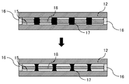
- FIG. 5 is a cross-sectional view schematically showing a cross section of the honeycomb structure 10 according to the first embodiment of the present invention, which is parallel to the stretching direction of the cell 15 before electromagnetic induction heating (upper figure) and after heating (lower figure). It is sectional drawing which shows typically the cross section parallel to the extending direction of the cell 15 of the honeycomb structure 10 which concerns on Embodiment 2 of this invention. It is the schematic of the exhaust gas flow path of the exhaust gas purification apparatus which incorporated the honeycomb structure which concerns on Embodiments 1 and 2 of this invention.
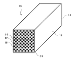
- FIG. 1 is a perspective view schematically showing a honeycomb structure 10 according to a first embodiment of the present invention.
- FIG. 2 is a cross-sectional view schematically showing a cross section of the honeycomb structure 10 according to the first embodiment of the present invention, which is parallel to the stretching direction of the cell 15.
- the honeycomb structure 10 is formed in a columnar shape, and is arranged inside the outer peripheral wall 11 and the outer peripheral wall 11, and a plurality of cells 15 that penetrate from one end face 13 to the other end face 14 to form a flow path. It is provided with a porous partition wall 12 for partitioning.
- a part of the plurality of cells 15 is provided with a wire small piece 18, which will be described in detail later.
- the position of the cell 15 provided with the wire piece 18 is not particularly limited.
- the cells 15 in which the small pieces 18 are not provided may be provided alternately. In this way, by alternately providing the cell 15 provided with the wire small piece 18 and the cell 15 not provided with the wire small piece 18, the electromagnetic induction heating efficiency becomes better.
- the arrangement position and the number of arrangements of the cells 15 provided with the wire small pieces 18 can be appropriately designed in consideration of the heating efficiency and the pressure loss of the honeycomb structure 10.
- the wire small pieces 18 are made of a magnetic material, and a plurality of the wire small pieces 18 are provided in the cell 15 at intervals along the direction in which the cell 15 extends, via the cushioning material 17. That is, the wire strips 18 and the cushioning material 17 are alternately provided adjacent to each other in the direction in which the cell 15 extends. Further, one end face 13 and the other end face 14 of the cell 15 in which the wire small piece 18 is provided are each provided with a mesh sealing portion 16. As the eye-sealing portion 16, one having the same structure as that used as the eye-sealing portion of a conventionally known honeycomb structure can be used.
- FIG. 3 shows a schematic view of the cell 15 provided with the wire strip 18 of the honeycomb structure 10.
- eye-sealing portions 16 are provided on both end faces 13 and 14, and a plurality of wire small pieces 18 provide cushioning material 17 along the direction in which the cell 15 extends so as to be in contact with the eye-sealing portions 16. They are provided apart from each other.
- a plurality of wire small pieces 18 made of a magnetic material are heated and expanded.
- the cushioning material 17 absorbs the portion extended by the expansion of the wire pieces 18. Therefore, it is possible to satisfactorily suppress the destruction of the eye-sealing portions provided on both end faces 13 and 14 of the cell 15 due to the expansion of the wire strip 18.
- the magnetic material wire small pieces 18 having a small surface area are used instead of magnetic fine particles having a large surface area. Therefore, when heating by electromagnetic induction heating, it is difficult to oxidize and deterioration of heating performance can be satisfactorily suppressed.
- the magnetic fine particles have a small volume, high-frequency induction heating is required for electromagnetic induction heating, which increases the cost for a power source and the like, but a wire small piece 18 having a larger volume than the magnetic fine particles is used. Therefore, the cost of the power supply and the like is reduced.
- the cushioning material 17 is provided between the adjacent wire pieces 18, but the present invention is not limited to this, and even if the space between the adjacent wire pieces 18 is formed. good.
- a part of the side surface of the wire piece 18 can be arranged in the cell by fixing it to the partition wall 12 with a joining material.
- the bonding material for example, a paste prepared by appropriately adding a pore-forming material, an organic binder and water to cordierite powder can be used. Even if a space is provided instead of the cushioning material 17 in this way, when the wire piece 18 made of a magnetic material rises and expands during electromagnetic induction heating as described above, the wire piece 18 expands due to the expansion of the wire piece 18. Since the space absorbs the portion, the breakage of the eye-sealing portions provided on both end faces 13 and 14 of the cell 15 can be satisfactorily suppressed.
- the wire strip 18 preferably has a coefficient of thermal expansion of 8-12 ⁇ 10 -6 / ° C.
- the coefficient of thermal expansion in the present specification refers to the coefficient of thermal expansion at 900 ° C. when 25 ° C. is used as a reference temperature. Examples of the magnetic material having a coefficient of thermal expansion of 8 to 12 ⁇ 10 -6 / ° C.
- FeCo alloy containing 10% by mass or more of Co examples include permendur, the balance Fe-49% by mass Co-2% by mass V, the balance Fe-17% by mass Co-2% by mass Cr-1% by mass Mo, and the like.
- stainless steel there are ferrite-based stainless steels such as SUS430f.
- the wire piece 18 is a magnetic material, is magnetized by a magnetic field, and the state of magnetization changes depending on the strength of the magnetic field. This is represented by the "magnetization curve".
- the magnetization curve may have a magnetic field H on the horizontal axis and a magnetic flux density B on the vertical axis (BH curve).
- the state in which no magnetic field is applied to the magnetic material is called the degaussing state and is represented by the origin O.
- the degaussing state When a magnetic field is applied, the magnetic flux density increases from the origin O and a saturated curve is drawn. This curve is the "initial magnetization curve".
- the slope of the straight line connecting the point on the initial magnetization curve and the origin is the "permeability".
- Permeability is a measure of the ease of magnetization of a magnetic material in the sense that a magnetic field permeates it.
- the magnetic permeability near the origin where the magnetic field is small is the “initial magnetic permeability”
- the maximum magnetic permeability on the initial magnetization curve is the “maximum magnetic permeability”.
- the wire strip 18 preferably has a maximum magnetic permeability of 10,000 or more. According to such a configuration, when the honeycomb structure 10 having the wire strip 18 is electromagnetically induced and heated, it reaches a temperature at which moisture vaporizes (about 100 ° C.) and further at a temperature at which the catalyst is activated (about 300 ° C.). The temperature can be raised in a short time.
- the wire strip 18 is more preferably having a maximum magnetic permeability of 25,000 or more, and even more preferably having a maximum magnetic permeability of 50,000 or more.
- Examples of the magnetic material having a maximum magnetic permeability of 10,000 or more include the balance Fe-10% by mass Si-5% by mass Al, 49% by mass Co-49% by mass Fe-2% by mass V, and the balance Fe-36% by mass Ni. , The balance Fe-45 mass% Ni and the like.
- the wire strip 18 preferably has a Curie temperature of 600 ° C. or higher.
- the Curie temperature of the wire strip 18 is 600 ° C. or higher, it is possible to reach a honeycomb temperature sufficient to raise the catalyst temperature above the catalyst activation temperature, and of course, the wire pieces are collected in the cell 15. It becomes easy to regenerate the honeycomb structure filter by burning and removing PM (particulate matter).
- the magnetic material having a curry temperature of 600 ° C. or higher include the balance Co-20% by mass Fe, the balance Co-25% by mass Ni-4% by mass Fe, the balance Fe-15 to 35% by mass Co, and the balance Fe-17.
- Mass% Co-2 mass% Cr-1 mass% Mo balance Fe-49 mass% Co-2 mass% V, balance Fe-18 mass% Co-10 mass% Cr-2 mass% Mo-1 mass% Al, Remaining Fe-27% by mass Co-1% by mass Nb, Remaining Fe-20% by mass Co-1% by mass Cr-2% by mass V, Remaining Fe-35% by mass Co-1% by mass Cr, Pure cobalt, Pure iron, There are electromagnetic soft iron, balance Fe-0.1 to 0.5% by mass Mn, balance Fe-3% by mass Si, and the like.
- the Curie temperature of a magnetic material refers to a temperature at which the characteristics of ferromagnetism is lost.
- the wire strip 18 preferably has an intrinsic resistance value of 10 ⁇ cm to 100 ⁇ cm at 25 ° C.
- the wire piece 18 has an intrinsic resistance value of 10 ⁇ cm or more at 25 ° C.
- the amount of heat generated by electromagnetic induction heating can be further increased due to the high resistance value.
- the wire piece 18 has an intrinsic resistance value of 100 ⁇ cm or less at 25 ° C.
- balance Fe-18 mass% Cr include the balance Fe-18 mass% Cr, the balance Fe-13 mass% Cr-2 mass% Si, and the balance Fe-20 mass% Cr-2 mass.
- % Si-2% by mass Mo balance Fe-10% by mass Si-5% by mass Al, balance Co-20% by mass Fe, balance Fe-15 to 35% by mass Co, balance Fe-49% by mass Co-2% by mass
- V the balance Fe-18 mass% Co-10 mass% Cr-2 mass% Mo-1 mass% Al, the balance Fe-36 mass% Ni, the balance Fe-45 mass% Ni, and the like.
- the wire small piece 18 preferably has a coercive force of 100 A / m or more. According to such a configuration, when the honeycomb structure 10 having the wire strip 18 is electromagnetically induced and heated, it reaches a temperature at which moisture vaporizes (about 100 ° C.) and further at a temperature at which the catalyst is activated (about 300 ° C.). The temperature can be raised in a short time.
- Magnetic materials having a coercive force of 100 A / m or more include the balance Fe-35 mass% Co, the balance Fe-20 mass% Co-1 mass% V, the balance Fe-13 mass% Cr-2 mass% Si, and the balance Fe. There are -18 mass% Cr and the like.
- the plurality of wire strips 18 each have a length of 1 to 20 mm in the direction in which the cell extends.
- the length of the wire piece 18 is 1 mm or more, the electromagnetic induction heating efficiency becomes better.
- the length of the wire small piece 18 is 20 mm or less, the extension of the wire small piece 18 due to the expansion is suppressed, and the destruction of the eye sealing portion 16 can be better suppressed.
- the length of each of the plurality of wire strips 18 in the extending direction of the cell is more preferably 3 to 15 mm, and even more preferably 4 to 6 mm, respectively.
- the plurality of wire strips 18 provided in the cell 15 may have the same length or different lengths from each other.
- the outer diameter of the plurality of wire small pieces 18 may be the same as the inner diameter of the cell 15, or may be formed smaller than the inner diameter of the cell 15. Further, the outer diameters of the plurality of wire strips 18 may be the same or different from each other.
- the cushioning material 17 or the space provided between the plurality of wire pieces 18 is all the extension due to the expansion when the plurality of wire pieces 18 provided in the cell 15 are heated and thermally expanded during electromagnetic induction heating. It may be of any size as long as it is formed to a size that can be absorbed.
- the length of the cushioning material 17 or the space in the direction in which the cell extends is preferably 1 mm or more. According to such a configuration, the plurality of wire small pieces 18 can better absorb the elongation due to expansion when the temperature is raised during electromagnetic induction heating and thermal expansion occurs.
- the length of the cushioning material 17 or the space in the extending direction is more preferably 2 mm or more, and even more preferably 2 to 3 mm.
- the plurality of cushioning materials 17 or the spaces provided in the cell 15 may have the same length or different lengths from each other.
- the total length of the cushioning material 17 or the space in the direction in which the cell 15 extends is 1/5 or more of the total length of the wire strip 18 in the direction in which the cell 15 extends. According to such a configuration, the plurality of wire small pieces 18 can better absorb the elongation due to expansion when the temperature is raised during electromagnetic induction heating and thermal expansion occurs. It is more preferable that the total length of the cushioning material 17 or the space in the direction in which the cell 15 extends is 1/5 to 1/2 of the total length of the wire strip 18 in the direction in which the cell 15 extends. , 1/5 to 1/3 is even more preferable.
- the cushioning material 17 preferably has a Young's modulus of 50 to 500 MPa.
- the Young's modulus of the cushioning material 17 is 500 MPa or less, it is possible to better absorb the elongation due to expansion when the temperature is raised during electromagnetic induction heating and thermal expansion occurs. Further, when the Young's modulus of the cushioning material 17 is 50 MPa or more, the mechanical strength can be maintained, and cracks generated by elongation due to expansion when the temperature is raised during electromagnetic induction heating and thermal expansion is satisfactorily suppressed. Can be done.
- the cushioning material 17 preferably has a Young's modulus of 100 to 400 MPa, and even more preferably 200 to 300 MPa.
- the cushioning material 17 preferably has a porosity of 40 to 70%.
- the porosity of the cushioning material 17 is 40% or more, the Young's modulus of the cushioning material 17 becomes low, and it is possible to better absorb the elongation due to expansion when the temperature rises during electromagnetic induction heating and thermal expansion occurs. .. Further, when the porosity of the cushioning material 17 is 70% or less, the mechanical strength of the cushioning material 17 can be maintained, and cracks generated by elongation due to expansion when the temperature is raised during electromagnetic induction heating and thermal expansion is good. Can be suppressed.
- the cushioning material 17 preferably has a porosity of 40 to 60%, and even more preferably 45 to 50%.
- the cushioning material 17 can be made of cordierite, silica, a ceramic material, or the like.
- the material of the partition wall 12 and the outer peripheral wall 11 of the honeycomb structure 10 is not particularly limited, but it is usually formed of a ceramic material because it needs to be a porous body having a large number of pores.
- a ceramic material for example, cordierite, silicon carbide, aluminum titanate, silicon nitride, mulite, alumina, silicon-silicon carbide composite material, silicon carbide-corgerite composite material, especially silicon-silicon carbide composite material or silicon carbide as the main component. Examples thereof include a sintered body.
- silicon carbide-based means that the honeycomb structure 10 contains silicon carbide in an amount of 50% by mass or more of the entire honeycomb structure 10.
- the honeycomb structure 10 contains a silicon-silicon carbide composite material as a main component because the honeycomb structure 10 contains a silicon-silicon carbide composite material (total mass) in an amount of 90% by mass or more of the entire honeycomb structure 10.
- the silicon-silicon carbide composite material contains silicon carbide particles as an aggregate and silicon as a binder for binding the silicon carbide particles, and a plurality of silicon carbide particles are formed between the silicon carbide particles. It is preferably bonded by silicon so as to form pores.
- the fact that the honeycomb structure 10 contains silicon carbide as a main component means that the honeycomb structure 10 contains silicon carbide (total mass) in an amount of 90% by mass or more of the entire honeycomb structure 10.
- the honeycomb structure 10 is formed of at least one ceramic material selected from the group consisting of cordierite, silicon carbide, aluminum titanate, silicon nitride, mullite, and alumina.
- the shape of the cell 15 of the honeycomb structure 10 is not particularly limited, but in a cross section orthogonal to the central axis of the honeycomb structure 10, it may be a polygon such as a triangle, a quadrangle, a pentagon, a hexagon, an octagon, a circle, or an ellipse. It is preferably present, and may have other irregular shapes.
- the outer shape of the honeycomb structure 10 is not particularly limited, but the end face is a circular columnar shape (cylindrical shape), the end face is an oval-shaped columnar shape, and the end face is a polygonal shape (quadrangle, pentagon, hexagon, heptagon, octagon). Etc.) can be a columnar shape or the like.
- the size of the honeycomb structure 10 is not particularly limited, but the length in the central axial direction is preferably 40 to 500 mm. Further, for example, when the outer shape of the honeycomb structure 10 is cylindrical, the radius of the end face thereof is preferably 50 to 500 mm.
- the thickness of the partition wall 12 of the honeycomb structure 10 is preferably 0.10 to 0.50 mm, and more preferably 0.25 to 0.45 mm in terms of ease of manufacture. For example, when it is 0.10 mm or more, the strength of the honeycomb structure 10 is further improved, and when it is 0.50 mm or less, the pressure loss can be further reduced when the honeycomb structure 10 is used as a filter. ..
- the thickness of the partition wall 12 is an average value measured by a method of observing a cross section in the central axis direction with a microscope.
- the porosity of the partition wall 12 constituting the honeycomb structure 10 is preferably 30 to 70%, and more preferably 40 to 65% in terms of ease of production. When it is 30% or more, the pressure loss is likely to decrease, and when it is 70% or less, the strength of the honeycomb structure 10 can be maintained.
- the average pore diameter of the porous partition wall 12 is preferably 5 to 30 ⁇ m, more preferably 10 to 25 ⁇ m. When it is 5 ⁇ m or more, the pressure loss can be reduced when it is used as a filter, and when it is 30 ⁇ m or less, the strength of the honeycomb structure 10 can be maintained.
- the terms "average pore diameter” and “porosity” mean the average pore diameter and porosity measured by the mercury intrusion method.
- the cell density of the honeycomb structure 10 is also not particularly limited, but is preferably in the range of 5 to 93 cells / cm 2 , more preferably in the range of 5 to 63 cells / cm 2, and 31 to 54 cells / cm 2. More preferably, it is in the range of cm 2.
- Such a honeycomb structure 10 is formed into a honeycomb shape having a partition wall 12 for partitioning a plurality of cells 15 which penetrate from one end face to the other end face and serve as a flow path of the fluid through the clay containing the ceramic raw material. Then, a honeycomb molded product is formed, and the honeycomb molded product is dried and then fired.
- the outer peripheral wall may be extruded integrally with the honeycomb structure portion and used as it is as the outer peripheral wall, or may be molded or fired.
- the outer periphery of the honeycomb molded body may be ground into a predetermined shape, and a coating material may be applied to the honeycomb structure obtained by grinding the outer periphery to form an outer peripheral coating.
- a honeycomb structure having an outer circumference is used without grinding the outermost circumference of the honeycomb structure, and the outer peripheral surface of the honeycomb structure having the outer circumference (that is, that is, The coating material may be further applied to the outer periphery of the outer periphery of the honeycomb structure to form an outer peripheral coating.
- the outer peripheral wall located on the outermost circumference.
- an outer peripheral wall having a two-layer structure is formed on the outer peripheral surface of the honeycomb structure, which is further laminated with an outer peripheral coating made of a coating material and is located at the outermost periphery.
- the outer peripheral wall may be extruded integrally with the honeycomb structure and fired as it is, and used as the outer peripheral wall without processing the outer circumference.
- the composition of the coating material is not particularly limited, and various known coating materials can be appropriately used.
- the coating material may further contain colloidal silica, an organic binder, clay and the like.
- the organic binder is preferably used in an amount of 0.05 to 0.5% by mass, more preferably 0.1 to 0.2% by mass.
- the clay is preferably used in an amount of 0.2 to 2.0% by mass, more preferably 0.4 to 0.8% by mass.
- honeycomb structure 10 is not limited to the integrated honeycomb structure 10 in which the partition wall 12 is integrally formed.
- the honeycomb structure 10 has a porous partition wall 12, and the partition wall 12 allows the flow path of the fluid.
- Honeycomb structure 10 having a structure in which a plurality of columnar honeycomb segments in which a plurality of cells 15 are formed are combined via a bonding material layer (hereinafter, may be referred to as “joining type honeycomb structure”). It may be.
- each of the fired honeycomb structures is used as a honeycomb segment, and the side surfaces of the plurality of honeycomb segments are joined and integrated with a joining material to form a honeycomb structure in which the honeycomb segments are joined. Can be done.
- the honeycomb structure in which the honeycomb segments are joined can be manufactured as follows, for example.
- the joining material to the joining surface (side surface) with the joining material adhesion prevention masks attached to both bottom surfaces of each honeycomb segment.
- these honeycomb segments are arranged adjacent to each other so that the side surfaces of the honeycomb segments face each other, and the adjacent honeycomb segments are crimped to each other and then heat-dried.
- the outer peripheral portion may be ground to form a desired shape (for example, a columnar shape), the outer peripheral surface may be coated with a coating material, and then heat-dried to form the outer peripheral wall 11.
- the material of the mask for preventing adhesion of the bonding material is not particularly limited, but synthetic resins such as polypropylene (PP), polyethylene terephthalate (PET), polyimide, and Teflon (registered trademark) can be preferably used.
- the mask preferably has an adhesive layer, and the material of the adhesive layer is preferably an acrylic resin, a rubber-based (for example, rubber containing natural rubber or synthetic rubber as a main component), or a silicon-based resin. preferable.
- an adhesive film having a thickness of 20 to 50 ⁇ m can be preferably used.
- the bonding material for example, a material prepared by mixing a ceramic powder, a dispersion medium (for example, water, etc.) and, if necessary, additives such as a binder, a glutinating agent, and a foamed resin can be used. ..
- the ceramics may be ceramics containing at least one selected from the group consisting of cordierite, mullite, zircon, aluminum titanate, silicon carbide, silicon nitride, zirconia, spinel, indialite, sapphirine, corundum, and titania. It is preferable that the material is the same as that of the honeycomb structure.
- the binder include polyvinyl alcohol, methyl cellulose, CMC (carboxymethyl cellulose) and the like.
- the honeycomb structure 10 may have a breathable surface layer on at least a part of the surface of the partition wall 12.
- having breathability means that the permeability of the surface layer is 1.0 ⁇ 10 -13 m 2 or more. From the viewpoint of further reducing the pressure loss, the permeability is preferably 1.0 ⁇ 10 -12 m 2 or more. Since the surface layer has air permeability, it is possible to suppress the pressure loss of the honeycomb structure 10 caused by the surface layer.
- permability refers to a physical characteristic value calculated by the following formula (1), and is a value that is an index indicating the passing resistance when a predetermined gas passes through the object (partition wall 12).
- C permeability (m 2 )
- F gas flow rate (cm 3 / s)
- T sample thickness (cm)
- V gas viscosity (dynes ⁇ sec / cm 2 ).
- D is the sample diameter (cm)
- P is the gas pressure (PSI).
- the partition wall 12 with the surface layer is cut out, the permeability is measured with the surface layer attached, and then the permeability is measured with the surface layer scraped off, and the surface layer and the partition wall are measured.
- the permeability of the surface layer is calculated from the ratio of the thickness of the base material and the measurement results of these permeability.
- the porosity of the surface layer is preferably 50% or more, more preferably 60% or more, and even more preferably 70% or more. By having a porosity of 50% or more, pressure loss can be suppressed. However, if the porosity is too high, the surface layer becomes brittle and easily peels off, so the porosity is preferably 90% or less.
- the difference between the mercury porosi curve in a sample having the surface layer and the base material and the mercury porosi curve of the base material only obtained by scraping and removing only the surface layer is the difference between the surface layer and the mercury porosi curve. It is regarded as a mercury porosi curve, and the pore ratio of the surface layer is calculated from the scraped mass and the mercury porosi curve. SEM imaging may be performed, and the porosity of the surface layer may be calculated from the area ratio of the void portion and the solid portion by image analysis of the surface layer portion.
- the average pore diameter of the surface layer is preferably 10 ⁇ m or less, more preferably 5 ⁇ m or less, further preferably 4 ⁇ m or less, and particularly preferably 3 ⁇ m or less.
- the average pore diameter is preferably 10 ⁇ m or less, more preferably 5 ⁇ m or less, further preferably 4 ⁇ m or less, and particularly preferably 3 ⁇ m or less.
- the mercury porosic curve pore volume frequency
- the peak is taken as the average pore diameter.
- an SEM image of the cross section of the honeycomb structure 10 is taken and the surface layer portion is image-analyzed to binarize the void portion and the solid portion, and 20 or more voids are randomly selected and the average of the inscribed circles thereof is selected. May be the average pore diameter.
- the thickness of the surface layer is not particularly limited. However, in order to obtain the effect of the surface layer more remarkably, the thickness of the surface layer is preferably 10 ⁇ m or more. On the other hand, from the viewpoint of avoiding an increase in pressure loss, the thickness of the surface layer is preferably 80 ⁇ m or less. The thickness of the surface layer is more preferably 50 ⁇ m or less.
- the honeycomb structure 10 on which the surface layer is formed is cut in a direction perpendicular to the direction in which the cell 15 extends, and the thickness of the surface layer is measured from the cross section thereof. It is possible to take the average of the measured values of the thickness of the points.
- a honeycomb structure having a porous partition wall and having a plurality of cells partitioned by the partition wall is produced.
- a cordierite-forming raw material is prepared as a material for clay. Since each component is blended in the cordierite-forming raw material so as to have the theoretical composition of the cordierite crystal, a silica source component, a magnesia source component, an alumina source component, and the like are blended.
- quartz and fused silica are preferably used as the silica source component, and the particle size of the silica source component is preferably 100 to 150 ⁇ m.
- magnesia source component examples include talc, magnesite and the like. Of these, talc is preferred.
- the talc is preferably contained in 37 to 43% by mass in the cordierite-forming raw material.
- the particle size (average particle size) of talc is preferably 5 to 50 ⁇ m, more preferably 10 to 40 ⁇ m.
- the magnesia (MgO) source component may contain Fe 2 O 3 , CaO, Na 2 O, K 2 O and the like as impurities.
- alumina source component those containing at least one of aluminum oxide and aluminum hydroxide are preferable in that there are few impurities.
- aluminum hydroxide is preferably contained in an amount of 10 to 30% by mass, and aluminum oxide is preferably contained in an amount of 0 to 20% by mass in the cordierite-forming raw material.
- a material (additive) for clay to be added to the cordierite raw material At least a binder and a pore-forming agent are used as additives. In addition to the binder and the pore-forming agent, a dispersant or a surfactant can be used.
- a substance that can be oxidized and removed by reacting with oxygen at a temperature equal to or lower than the firing temperature of cordierite, or a low melting point reactant having a melting point at a temperature equal to or lower than the firing temperature of corderite can be used.
- the substance that can be oxidatively removed include resins (particularly particulate resin) and graphite (particularly particulate graphite).
- the low melting point reactant at least one metal selected from the group consisting of iron, copper, zinc, lead, aluminum, and nickel, and alloys containing these metals as main components (for example, carbon steel in the case of iron). , Cast iron, stainless steel), or alloys containing two or more kinds of main components can be used.
- the low melting point reactant is preferably a powder-granular or fibrous iron alloy. Further, the particle size or fiber diameter (average diameter) is preferably 10 to 200 ⁇ m. Examples of the shape of the low melting point reactant include a spherical shape, a lozenge shape, a konpeito shape, and the like, and these shapes are preferable because the shape of the pores can be easily controlled.
- binder examples include hydroxypropylmethyl cellulose, methyl cellulose, hydroxyethyl cellulose, carboxymethyl cellulose, polyvinyl alcohol and the like.
- dispersant for example, dextrin, polyalcohol and the like can be mentioned.
- surfactant for example, fatty acid soap can be mentioned.
- the additive may be used alone or in combination of two or more.
- the prepared clay is molded into a honeycomb shape by an extrusion molding method, an injection molding method, a press molding method, etc. to obtain a raw honeycomb molded product. It is preferable to adopt an extrusion molding method because continuous molding is easy and, for example, cordierite crystals can be oriented.
- the extrusion molding method can be performed using an apparatus such as a vacuum clay kneader, a ram type extrusion molding machine, and a twin-screw type continuous extrusion molding machine.
- honeycomb molded body is dried and adjusted to a predetermined size to obtain a honeycomb dried body.
- the honeycomb molded body can be dried by hot air drying, microwave drying, dielectric drying, vacuum drying, vacuum drying, freeze drying and the like. Since the whole can be dried quickly and uniformly, it is preferable to perform drying by combining hot air drying and microwave drying or dielectric drying.
- a wire piece made of a magnetic material and a cushioning material made of cordierite or the like are alternately provided in a predetermined cell of the honeycomb dried body.
- a space is provided instead of the cushioning material, a joining material is provided on the side surface of the wire piece, and the wire piece is fixed to the cell wall.
- the raw material for the sealing part As the material of the sealing portion (slurry for sealing), the same material for clay as the partition wall (honeycomb dried body) may be used, or a different material may be used. Specifically, it is obtained by mixing a ceramic raw material, a surfactant, and water, adding a sintering aid, a pore-forming agent, etc. as necessary to form a slurry, and kneading the mixture using a mixer or the like. be able to.
- the material of the sealing portion slurry for sealing
- the same material for clay as the partition wall honeycomb dried body
- a different material may be used. Specifically, it is obtained by mixing a ceramic raw material, a surfactant, and water, adding a sintering aid, a pore-forming agent, etc. as necessary to form a slurry, and kneading the mixture using a mixer or the like. be able to.
- a part of the cell opening on one end face of the dried honeycomb is masked, and the end face is immersed in a storage container in which the sealing slurry is stored to form an unmasked cell. Fill with the sealing slurry.
- a part of the cell opening on the other end face of the dried honeycomb is masked, and the end face is immersed in a storage container in which the sealing slurry is stored to obtain an unmasked cell. Is filled with a slurry for sealing. In this way, both ends of the cell provided with the wire strips are sealed. Then, it is dried and fired to obtain a honeycomb structure having a mesh sealing portion.
- the drying conditions the same conditions as the conditions for drying the honeycomb molded body can be adopted. Further, the firing conditions can be usually 3 to 15 hours at a temperature of 1410 to 1440 ° C. under an air atmosphere when a cordierite-forming raw material is used.
- the outer peripheral surface may be ground to remove the outer peripheral wall.
- a coating material is applied to the outer periphery of the honeycomb structure from which the outer peripheral wall has been removed in this way to form an outer peripheral coating.
- the outer peripheral surface is ground, a part of the outer peripheral wall may be ground and removed, and an outer peripheral coating may be formed on the portion with a coating material.
- the coating material for example, it can be prepared using a biaxial rotary vertical mixer.
- the coating material may further contain colloidal silica, an organic binder, clay and the like.
- the organic binder is preferably used in an amount of 0.05 to 0.5% by mass, more preferably 0.1 to 0.2% by mass.
- the clay is preferably used in an amount of 0.2 to 2.0% by mass, more preferably 0.4 to 0.8% by mass.
- a coating material is applied to the outer peripheral surface of the honeycomb structure produced earlier, and the applied coating material is dried to form an outer peripheral coating.
- the honeycomb structure is placed on a rotary table and rotated, and the coating material is discharged from the blade-shaped coating nozzle while the coating nozzle is applied along the outer peripheral portion of the honeycomb structure.
- a method of pressing and applying can be mentioned. With this configuration, the coating material can be applied with a uniform thickness. Further, the surface roughness of the formed outer peripheral coating is reduced, and it is possible to form an outer peripheral coating which is excellent in appearance and is not easily damaged by thermal shock.
- a coating material is applied to the entire outer peripheral surface of the honeycomb structure to form an outer peripheral coating.
- a coating material may be partially applied to form the outer peripheral coating.
- a coating material may be applied to the entire outer peripheral surface of the honeycomb structure to form an outer peripheral coating.
- the moisture content in the coating material can be reduced by holding it at room temperature for 24 hours or more. After drying 25% or more, a method of removing water and organic substances by holding at 600 ° C. for 1 hour or more in an electric furnace can be preferably used.
- the opening of the cell of the honeycomb structure when the opening of the cell of the honeycomb structure is not sealed in advance, the opening of the cell may be sealed after forming the outer peripheral coating.
- the silicon carbide powder contained in the coating material is colored by irradiating the outer peripheral surface of the obtained honeycomb structure with a laser, the outer peripheral coating of the obtained honeycomb structure is irradiated with a laser beam.
- the product information and the like may be printed (marked).
- the laser light used for marking with a laser for example, a carbon dioxide (CO 2 ) laser, a YAG laser, and a YVO 4 laser can be mentioned as preferable examples.
- the conditions of the laser that irradiates the laser light can be appropriately selected according to the type of laser used. For example, when a CO 2 laser is used, the output is 15 to 25 W and the scan speed is 400 to 600 mm /. It is preferable to mark with s. By marking in this way, the irradiated portion is colored so as to exhibit a dark color such as black to green, and the contrast due to the coloring with the non-irradiated portion becomes extremely good.
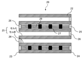
- FIG. 4 is a cross-sectional view schematically showing a cross section of the honeycomb structure 20 according to the second embodiment of the present invention, which is parallel to the stretching direction of the cell 25.
- the honeycomb structure 20 is formed in a columnar shape, and is arranged inside the outer peripheral wall 21 and the outer peripheral wall 21, and a plurality of cells 25 that penetrate from one end face 23 to the other end face 24 to form a flow path. It is provided with a porous partition wall 22 for partitioning.
- a small wire piece 28 is provided in a part of the plurality of cells 25.
- the wire strips 28 are made of a magnetic material, and a plurality of the wire strips 28 are provided in the cell 25 at intervals along the direction in which the cell 25 extends, via the cushioning material 27.
- a space may be provided between the adjacent wire pieces 28 instead of the cushioning material 27.
- one end face 23 and the other end face 24 of the cell 25 in which the wire small piece 28 is provided are each provided with a mesh sealing portion 26.
- the honeycomb structure 20 according to the second embodiment of the present invention is different from the honeycomb structure 10 according to the first embodiment of the present invention in that it forms a filter structure. That is, in the honeycomb structure 20, the cells 25 are alternately arranged with a plurality of cells A having one end face 23 side open and having a sealing portion 29 on the other end face 24, and the other end face. A plurality of cells B having an opening on the 24 side and having a sealing portion 29 on one end surface 23 are provided.
- the number, arrangement, shape, etc. of cells A and B are not limited, and can be appropriately designed as needed.
- Such a honeycomb structure 20 is a filter for purifying particulate matter (carbon fine particles) in exhaust gas (for example, a gasoline particulate filter (hereinafter, also referred to as “GPF”), or a diesel particulate filter (hereinafter, “GPF”). It can also be used as "DPF”)).
- a gasoline particulate filter hereinafter, also referred to as “GPF”
- GPF gasoline particulate filter
- DPF diesel particulate filter
- the honeycomb structure 20 according to the second embodiment of the present invention may have a catalyst supported on the surface of the porous partition wall 22 forming the inner walls of the plurality of cells 25 and / or in the pores of the partition wall 22. good.
- the type of catalyst is not particularly limited, and can be appropriately selected depending on the purpose and use of the honeycomb structure 20.
- a noble metal catalyst or a catalyst other than these can be mentioned.
- a noble metal catalyst a noble metal such as platinum (Pt), palladium (Pd), or rhodium (Rh) is supported on the surface of the alumina pores, and a three-way catalyst containing a co-catalyst such as ceria or zirconia, an oxidation catalyst, or an alkali.
- An example is a NO x storage reduction catalyst (LNT catalyst) containing earth metal and platinum as storage components of nitrogen oxide (NO x).
- LNT catalyst NO x storage reduction catalyst
- catalysts that do not use noble metals include NO x selective reduction catalysts (SCR catalysts) containing copper-substituted or iron-substituted zeolites. Further, two or more kinds of catalysts selected from the group consisting of these catalysts may be used.
- the method of supporting the catalyst is also not particularly limited, and can be carried out according to the conventional method of supporting the catalyst on the honeycomb structure.
- the effect of the cushioning material 27 or the space provided between the wire small piece 28 of the honeycomb structure 20 and the adjacent wire small piece 28 according to the second embodiment of the present invention is in the first embodiment of the present invention shown in FIG. This is the same as the honeycomb structure 10. That is, when the honeycomb structure 20 having the cell 25 having such a structure is electromagnetically induced and heated, the plurality of wire small pieces 28 made of the magnetic material are heated and expanded respectively. At this time, since the cushioning material 27 or the space is provided between the adjacent wire pieces 28, the cushioning material 27 or the space absorbs the portion extended by the expansion of the wire pieces 28.
- the magnetic material wire small pieces 28 having a small surface area are used instead of magnetic fine particles having a large surface area. Therefore, when heating by electromagnetic induction heating, it is difficult to oxidize and deterioration of heating performance can be satisfactorily suppressed. Further, since the magnetic fine particles have a small volume, high-frequency induction heating is required for electromagnetic induction heating, which increases the cost for a power source and the like, but a wire small piece 28 having a larger volume than the magnetic fine particles is used. Therefore, the cost of the power supply and the like is reduced.
- the method for manufacturing the honeycomb structure 20 according to the second embodiment of the present invention is the same as that of the present invention, except that in the dried honeycomb body, a mesh sealing portion is provided also for a predetermined cell other than the cell in which the wire piece is provided. It can be carried out in the same manner as the method for manufacturing the honeycomb structure 10 according to the first embodiment.
- the exhaust gas purification device can be configured by using the honeycomb structure according to each embodiment of the present invention described above.
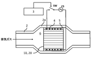
- FIG. 5 shows, as an example, a schematic view of the exhaust gas flow path of the exhaust gas purification device 6 in which the honeycomb structure 10 or the honeycomb structure 20 is incorporated.
- the exhaust gas purification device 6 has honeycomb structures 10 and 20 and a coil wiring 4 that spirally orbits the outer periphery of the honeycomb structures 10 and 20. Further, the exhaust gas purification device 6 has a metal pipe 2 for accommodating the honeycomb structures 10 and 20 and the coil wiring 4.
- the exhaust gas purification device 6 can be arranged in the enlarged diameter portion 2a of the metal pipe 2.
- the coil wiring 4 may be fixed in the metal tube 2 by the fixing member 5.
- the fixing member 5 is preferably a heat-resistant member such as a ceramic fiber.
- Honeycomb structures 10 and 20 may carry a catalyst.
- the coil wiring 4 is spirally wound around the outer circumferences of the honeycomb structures 10 and 20. It is also assumed that two or more coil wirings 4 are used.
- An alternating current supplied from the alternating current power supply CS flows through the coil wiring 4 in response to the on (ON) of the switch SW, and as a result, a magnetic field that changes periodically is generated around the coil wiring 4.
- the on / off of the switch SW is controlled by the control unit 3.
- the control unit 3 can turn on the switch SW in synchronization with the start of the engine and allow an alternating current to flow through the coil wiring 4. It should be noted that a mode in which the control unit 3 turns on the switch SW regardless of the start of the engine (for example, in response to the operation of the heating switch pushed by the driver) is also assumed.
- the temperature of the honeycomb structures 10 and 20 rises according to the change of the magnetic field according to the alternating current flowing through the coil wiring 4. As a result, carbon fine particles and the like collected by the honeycomb structures 10 and 20 are burned.
- raising the temperature of the honeycomb structures 10 and 20 raises the temperature of the catalyst supported by the catalyst carrier contained in the honeycomb structures 10 and 20 and causes a catalytic reaction. Be promoted.
- carbon monoxide (CO), oxide oxide (NO x ), and hydrocarbon (CH) are oxidized or reduced to carbon dioxide (CO 2 ), nitrogen (N 2 ), and water (H 2 O).
- a rectangular parallelepiped cordierite honeycomb with a length of 11 mm, a width of 19 mm, a length of 25 mm, a partition thickness of 0.1 mm, and a distance between partition walls of about 1 mm is formed in one cell at 5 ⁇ 5 cell intervals along the direction in which the cells extend.
- a plurality of small wire pieces having the length and the magnetic material shown in Table 1 were provided via a cushioning material. Each cushioning material was made of cordierite and silica and had a length of 1 mm along the direction in which the cell extended.
- eye-sealing portions were provided at both ends of the cell provided with the wire pieces.
- ⁇ Comparative Examples 1 and 2> The same rectangular parallelepiped honeycomb made of cordierite as in Example 1 was prepared. Next, a wire having a length shown in Table 1 and a wire made of a magnetic material was provided in one cell at an interval of 5 ⁇ 5 cells along the direction in which the cell was extended. In Comparative Examples 1 and 2, no cushioning material was provided, and one wire was provided in the cell so as to reach from the eye-sealing portion at one end to the eye-sealing portion at the other end.
- the coefficient of thermal expansion of the magnetic material shown in Table 1 was defined as the coefficient of thermal expansion at 900 ° C. when 25 ° C. was used as a reference temperature.
- the Curie temperature shown in Table 1 is a temperature at which the ferromagnetic property is lost.
- the porosity of the cushioning material shown in Table 1 was measured by image analysis from the SEM image of the cross section of the cushioning material.
- the Young's modulus of the cushioning material shown in Table 1 was measured in accordance with JIS R1602.
- honeycomb structures according to Examples 1 to 7 all use wire small pieces having a small surface area as the magnetic material, they are difficult to oxidize even when heated by electromagnetic induction heating, and deterioration of heating performance is satisfactorily suppressed. Also, after the temperature was raised, no cracks were generated in the sealing portion. On the other hand, in each of the honeycomb structures according to Comparative Examples 1 and 2, one wire that does not provide a cushioning material and reaches the inside of the cell from the eye-sealing portion at one end to the eye-sealing portion at the other end. Therefore, after the temperature was raised, cracks were generated in the sealing portion.
Landscapes
- Chemical & Material Sciences (AREA)
- Engineering & Computer Science (AREA)
- Chemical Kinetics & Catalysis (AREA)
- Physics & Mathematics (AREA)
- Combustion & Propulsion (AREA)
- Mechanical Engineering (AREA)
- General Engineering & Computer Science (AREA)
- Geometry (AREA)
- Toxicology (AREA)
- Materials Engineering (AREA)
- Organic Chemistry (AREA)
- Health & Medical Sciences (AREA)
- Thermal Sciences (AREA)
- Filtering Materials (AREA)
- Processes For Solid Components From Exhaust (AREA)
- Catalysts (AREA)
- Exhaust Gas After Treatment (AREA)
- Filtering Of Dispersed Particles In Gases (AREA)
- Porous Artificial Stone Or Porous Ceramic Products (AREA)
- Exhaust Gas Treatment By Means Of Catalyst (AREA)
Abstract
Description
(1)外周壁と、
前記外周壁の内側に配設され、一方の端面から他方の端面まで貫通して流路を形成する複数のセルを区画形成する多孔質の隔壁と、
を有する柱状のハニカム構造体であって、
前記セル内において、前記セルが延びる方向に沿って、磁性体で構成された複数のワイヤー小片が、空間または緩衝材を介して離間して設けられているハニカム構造体。
(2)(1)のハニカム構造体と、
前記ハニカム構造体の外周を螺旋状に周回するコイル配線と、
前記ハニカム構造体及び前記コイル配線を収容する金属管と、
を有する排気ガス浄化装置。
(実施形態1)
図1は、本発明の実施形態1に係るハニカム構造体10を模式的に示す斜視図である。図2は、本発明の実施形態1に係るハニカム構造体10のセル15の延伸方向に平行な断面を模式的に示す断面図である。ハニカム構造体10は、柱状に形成されており、外周壁11と、外周壁11の内側に配設され、一方の端面13から他方の端面14まで貫通して流路を形成する複数のセル15を区画形成する多孔質の隔壁12とを備える。
このように緩衝材17の代わりに空間を設けた構成としても、上述のように電磁誘導加熱時に磁性体で構成されたワイヤー小片18が昇温して膨張したとき、ワイヤー小片18の膨張で延びた部分を空間が吸収するために、セル15の両端面13、14に設けた目封止部の破壊を良好に抑制することができる。
8~12×10-6/℃の熱膨張係数を有する磁性体としては、Coを10質量%以上含むFeCo合金、または、ステンレス鋼等がある。Coを10質量%以上含むFeCo合金としては、パーメンジュール、残部Fe-49質量%Co-2質量%V、残部Fe-17質量%Co-2質量%Cr-1質量%Mo等がある。また、ステンレス鋼としては、SUS430fをはじめとするフェライト系ステンレス等がある。

次に、本発明の実施形態2に係るハニカム構造体20について説明する。図4は、本発明の実施形態2に係るハニカム構造体20のセル25の延伸方向に平行な断面を模式的に示す断面図である。ハニカム構造体20は、柱状に形成されており、外周壁21と、外周壁21の内側に配設され、一方の端面23から他方の端面24まで貫通して流路を形成する複数のセル25を区画形成する多孔質の隔壁22とを備える。
上述した本発明の各実施形態に係るハニカム構造体を用いて排気ガス浄化装置を構成することができる。図5は、例として、ハニカム構造体10またはハニカム構造体20が組み込まれた排気ガス浄化装置6の排気ガス流路の概略図を示している。排気ガス浄化装置6は、ハニカム構造体10、20とハニカム構造体10、20の外周を螺旋状に周回するコイル配線4とを有する。また、排気ガス浄化装置6は、ハニカム構造体10、20及びコイル配線4を収容する金属管2を有する。金属管2の拡径部2aに排気ガス浄化装置6を配置することができる。コイル配線4は固定部材5によって金属管2内に固定されてもよい。固定部材5は、セラミック繊維等の耐熱性部材であることが好ましい。ハニカム構造体10、20は触媒を担持してもよい。
縦11mm、横19mm、長さ25mm、隔壁厚さが0.1mm、隔壁間距離が約1mmの直方体のコージェライト製ハニカムに、5×5セル間隔において1セル内に、セルが延びる方向に沿って、表1に示す長さ及び磁性体で構成されたワイヤー小片を、緩衝材を介して複数設けた。各緩衝材は、コージェライト、シリカで形成し、セルが延びる方向に沿って、1mmの長さとした。また、ワイヤー小片を設けたセルの両端には、目封止部を設けた。
実施例1と同じ直方体のコージェライト製ハニカムを準備した。次に、5×5セル間隔において1セル内に、セルが延びる方向に沿って、表1に示す長さ及び磁性体で構成されたワイヤーを設けた。比較例1及び2では、緩衝材は設けず、セル内には一端の目封止部から他端の目封止部まで到達するような1本のワイヤーを設けた。
次に、電磁誘導加熱装置を用いて、実施例1~7及び比較例1及び2に係るハニカム構造体の加熱試験を行い、ハニカム構造体の端面の温度(表1の誘導加熱時温度)を赤外線温度計で測定した。投入電力は、4kWとし、電磁誘導加熱周波数は500kHzとした。
昇温後、目封止部にクラックが生じているか否かを確認した。
表1に記載の磁性体の熱膨張係数は、25℃を基準温度としたときの900℃での熱膨張係数とした。また、表1に記載のキュリー温度は、強磁性の特性を失う温度とした。また、表1に記載の緩衝材の気孔率は、緩衝材の断面のSEM画像から画像解析によって測定した。また、表1に記載の緩衝材のヤング率の測定はJIS R1602に準拠して行った。
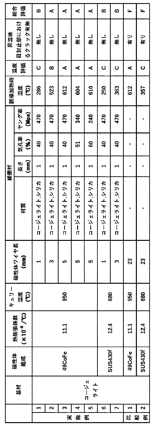
表1の温度評価の基準は以下の通りである。
A:600℃以上 〔スス(ディーゼル由来)の燃焼温度〕
B:500℃以上600℃未満 〔スス(ガソリン由来)の燃焼温度〕
C:250℃以上500℃未満 〔自動車排気ガス浄化触媒の必要温度〕
D:250℃未満
A:GPF(ガソリン・パーティキュレート・フィルター)への利用が可能
B:自動車排気ガス浄化触媒用担体への利用が可能
F:GPF及び自動車排気ガス浄化触媒用担体への利用が不可
一方、比較例1及び2に係るハニカム構造体は、いずれも、緩衝材は設けず、セル内に、一端の目封止部から他端の目封止部まで到達するような1本のワイヤーを設けたため、昇温後、目封止部にクラックが生じていた。
2 金属管
3 制御部
4 コイル配線
5 固定部材
6 排気ガス浄化装置
11 外周壁
12、22 隔壁
13、14、23、24 端面
15 セル
16、26 目封止部
17、27 緩衝材
18、28 ワイヤー小片
25 セル(セルA+セルB)
Claims (14)
- 外周壁と、
前記外周壁の内側に配設され、一方の端面から他方の端面まで貫通して流路を形成する複数のセルを区画形成する多孔質の隔壁と、
を有する柱状のハニカム構造体であって、
前記セル内において、前記セルが延びる方向に沿って、磁性体で構成された複数のワイヤー小片が、空間または緩衝材を介して離間して設けられているハニカム構造体。 - 前記セルが延びる方向における、前記ワイヤー小片の長さが、それぞれ1~20mmである請求項1に記載のハニカム構造体。
- 前記セルが延びる方向における、前記空間または前記緩衝材の長さが、それぞれ1mm以上である請求項1または2に記載のハニカム構造体。
- 前記セルが延びる方向における、前記空間または前記緩衝材の長さの合計が、前記セルが延びる方向における、前記ワイヤー小片の長さの合計の1/5以上である請求項1~3のいずれか一項に記載のハニカム構造体。
- 前記緩衝材のヤング率が50~500MPaである請求項1~4のいずれか一項に記載のハニカム構造体。
- 前記緩衝材の気孔率が40~70%である請求項1~5のいずれか一項に記載のハニカム構造体。
- 前記緩衝材が、コージェライト、シリカ、または、セラミックス材料で構成されている請求項1~6のいずれか一項に記載のハニカム構造体。
- 前記ワイヤー小片が、600℃以上のキュリー温度を有する請求項1~7のいずれか一項に記載のハニカム構造体。
- 前記ワイヤー小片が、8~12×10-6/℃の熱膨張係数を有する請求項1~8のいずれか一項に記載のハニカム構造体。
- 前記ワイヤー小片が、Coを10質量%以上含むFeCo合金、または、ステンレス鋼で構成されている請求項1~9のいずれか一項に記載のハニカム構造体。
- 前記隔壁及び外周壁がセラミックス材料で構成されている請求項1~10のいずれか一項に記載のハニカム構造体。
- 前記セラミックス材料がコージェライト、炭化珪素、チタン酸アルミニウム、窒化珪素、ムライト、及び、アルミナからなる群から選択される少なくとも1つである請求項11に記載のハニカム構造体。
- 前記セルは、
前記一方の端面側が開口して前記他方の端面に目封止部を有する複数のセルAと、
前記セルAとそれぞれ交互に配置され、前記他方の端面側が開口して前記一方の端面に目封止部を有する複数のセルBと、
を含む請求項1~12のいずれか一項に記載のハニカム構造体。 - 請求項1~13のいずれか一項に記載のハニカム構造体と、
前記ハニカム構造体の外周を螺旋状に周回するコイル配線と、
前記ハニカム構造体及び前記コイル配線を収容する金属管と、
を有する排気ガス浄化装置。
Priority Applications (4)
| Application Number | Priority Date | Filing Date | Title |
|---|---|---|---|
| CN202180007731.7A CN115023538B (zh) | 2020-02-07 | 2021-02-08 | 蜂窝结构体及尾气净化装置 |
| DE112021000439.5T DE112021000439B4 (de) | 2020-02-07 | 2021-02-08 | Wabenstruktur und abgasreinigungsvorrichtung |
| JP2021576211A JP7246525B2 (ja) | 2020-02-07 | 2021-02-08 | ハニカム構造体及び排気ガス浄化装置 |
| US17/810,874 US12383852B2 (en) | 2020-02-07 | 2022-07-06 | Honeycomb structure and exhaust gas purifying device |
Applications Claiming Priority (2)
| Application Number | Priority Date | Filing Date | Title |
|---|---|---|---|
| JP2020020108 | 2020-02-07 | ||
| JP2020-020108 | 2020-02-07 |
Related Child Applications (1)
| Application Number | Title | Priority Date | Filing Date |
|---|---|---|---|
| US17/810,874 Continuation US12383852B2 (en) | 2020-02-07 | 2022-07-06 | Honeycomb structure and exhaust gas purifying device |
Publications (1)
| Publication Number | Publication Date |
|---|---|
| WO2021157746A1 true WO2021157746A1 (ja) | 2021-08-12 |
Family
ID=77200686
Family Applications (1)
| Application Number | Title | Priority Date | Filing Date |
|---|---|---|---|
| PCT/JP2021/004680 Ceased WO2021157746A1 (ja) | 2020-02-07 | 2021-02-08 | ハニカム構造体及び排気ガス浄化装置 |
Country Status (5)
| Country | Link |
|---|---|
| US (1) | US12383852B2 (ja) |
| JP (1) | JP7246525B2 (ja) |
| CN (1) | CN115023538B (ja) |
| DE (1) | DE112021000439B4 (ja) |
| WO (1) | WO2021157746A1 (ja) |
Cited By (1)
| Publication number | Priority date | Publication date | Assignee | Title |
|---|---|---|---|---|
| TWI827194B (zh) * | 2022-08-09 | 2023-12-21 | 漢科系統科技股份有限公司 | 利用高週波熱源之廢氣濾淨設備 |
Families Citing this family (1)
| Publication number | Priority date | Publication date | Assignee | Title |
|---|---|---|---|---|
| JP7594471B2 (ja) * | 2021-03-16 | 2024-12-04 | 日本碍子株式会社 | ハニカム構造体及び電気加熱式担体 |
Citations (4)
| Publication number | Priority date | Publication date | Assignee | Title |
|---|---|---|---|---|
| JPH11336534A (ja) * | 1998-05-26 | 1999-12-07 | Toyota Motor Corp | 内燃機関の誘導発熱式浄化装置 |
| WO2016021186A1 (ja) * | 2014-08-07 | 2016-02-11 | 日本特殊陶業株式会社 | 排ガス流路部材、排ガス浄化装置、その昇温方法、及び、排ガス流路部材用の磁性体 |
| JP2017002785A (ja) * | 2015-06-09 | 2017-01-05 | トヨタ自動車株式会社 | 内燃機関の排気浄化システム |
| JP2019188272A (ja) * | 2018-04-18 | 2019-10-31 | 日本碍子株式会社 | 触媒担体及びその製造方法、並びに排気ガス浄化装置 |
Family Cites Families (18)
| Publication number | Priority date | Publication date | Assignee | Title |
|---|---|---|---|---|
| GB1329907A (en) * | 1970-12-31 | 1973-09-12 | Tokyo Roki Kk | Separating device for fine particles such as carbon particles from engine exhaust gas |
| US4969328A (en) * | 1986-10-21 | 1990-11-13 | Kammel Refaat A | Diesel engine exhaust oxidizer |
| GB8818463D0 (en) * | 1988-08-03 | 1988-09-07 | Loughborough Consult Ltd | Apparatus & method for removing particulate matter from exhaust gases of i c engine |
| DE3908581A1 (de) * | 1989-03-16 | 1990-09-20 | Schwaebische Huettenwerke Gmbh | Verfahren zur herstellung eines filter- oder katalysatorkoerpers |
| JP5064432B2 (ja) * | 2009-03-24 | 2012-10-31 | 日本碍子株式会社 | ハニカム触媒体 |
| US9737851B2 (en) * | 2012-08-24 | 2017-08-22 | Advanced Technology Emission Solutions Inc. | Process for manufacturing a component for a catalytic converter |
| US10132221B2 (en) | 2013-09-18 | 2018-11-20 | Advanced Technology Emission Solutions Inc. | Apparatus and method for gaseous emissions treatment with enhanced catalyst distribution |
| US11060433B2 (en) * | 2013-09-18 | 2021-07-13 | Advanced Technology Emission Solutions Inc. | Retention of wires in an induction heated gaseous emissions treatment unit |
| US10280821B2 (en) * | 2013-09-18 | 2019-05-07 | Advanced Technology Emission Solutions Inc. | Gaseous emissions treatment structures with electrohydrodynamic heat and mass transfer |
| US10207222B2 (en) * | 2013-09-18 | 2019-02-19 | Advanced Technology Emission Solutions Inc. | Apparatus and method for gaseous emissions treatment with induction heating of loop conductors |
| JP2016055282A (ja) * | 2014-09-11 | 2016-04-21 | 日本碍子株式会社 | ハニカム構造体 |
| DE112016000619T5 (de) * | 2015-02-05 | 2017-11-30 | Honda Motor Co., Ltd. | Wabenstruktur |
| JP6577895B2 (ja) * | 2016-03-30 | 2019-09-18 | 日本碍子株式会社 | ハニカム構造体 |
| JP6809963B2 (ja) * | 2017-03-30 | 2021-01-06 | 日本碍子株式会社 | ハニカム構造体 |
| JP6782659B2 (ja) * | 2017-03-30 | 2020-11-11 | 日本碍子株式会社 | ハニカム構造体 |
| JP6743796B2 (ja) * | 2017-09-29 | 2020-08-19 | 株式会社デンソー | 電気加熱式触媒 |
| JP6496385B2 (ja) * | 2017-11-06 | 2019-04-03 | 日本碍子株式会社 | ハニカム構造体、及びその製造方法 |
| CN113557088B (zh) * | 2019-03-22 | 2023-09-05 | 日本碍子株式会社 | 蜂窝结构体及废气净化装置 |
-
2021
- 2021-02-08 JP JP2021576211A patent/JP7246525B2/ja active Active
- 2021-02-08 CN CN202180007731.7A patent/CN115023538B/zh active Active
- 2021-02-08 WO PCT/JP2021/004680 patent/WO2021157746A1/ja not_active Ceased
- 2021-02-08 DE DE112021000439.5T patent/DE112021000439B4/de active Active
-
2022
- 2022-07-06 US US17/810,874 patent/US12383852B2/en active Active
Patent Citations (4)
| Publication number | Priority date | Publication date | Assignee | Title |
|---|---|---|---|---|
| JPH11336534A (ja) * | 1998-05-26 | 1999-12-07 | Toyota Motor Corp | 内燃機関の誘導発熱式浄化装置 |
| WO2016021186A1 (ja) * | 2014-08-07 | 2016-02-11 | 日本特殊陶業株式会社 | 排ガス流路部材、排ガス浄化装置、その昇温方法、及び、排ガス流路部材用の磁性体 |
| JP2017002785A (ja) * | 2015-06-09 | 2017-01-05 | トヨタ自動車株式会社 | 内燃機関の排気浄化システム |
| JP2019188272A (ja) * | 2018-04-18 | 2019-10-31 | 日本碍子株式会社 | 触媒担体及びその製造方法、並びに排気ガス浄化装置 |
Cited By (1)
| Publication number | Priority date | Publication date | Assignee | Title |
|---|---|---|---|---|
| TWI827194B (zh) * | 2022-08-09 | 2023-12-21 | 漢科系統科技股份有限公司 | 利用高週波熱源之廢氣濾淨設備 |
Also Published As
| Publication number | Publication date |
|---|---|
| US12383852B2 (en) | 2025-08-12 |
| DE112021000439T5 (de) | 2022-10-20 |
| CN115023538B (zh) | 2023-09-08 |
| US20220362704A1 (en) | 2022-11-17 |
| JPWO2021157746A1 (ja) | 2021-08-12 |
| CN115023538A (zh) | 2022-09-06 |
| DE112021000439B4 (de) | 2025-12-18 |
| JP7246525B2 (ja) | 2023-03-27 |
Similar Documents
| Publication | Publication Date | Title |
|---|---|---|
| JP7423532B2 (ja) | ハニカム構造体、排気ガス浄化装置、排気システム及びハニカム構造体の製造方法 | |
| US12121886B2 (en) | Honeycomb structure and exhaust gas purifying device | |
| US11369952B2 (en) | Honeycomb structure and exhaust gas purifying device | |
| US12209526B2 (en) | Honeycomb structure and exhaust gas purifying device | |
| US20220118391A1 (en) | Honeycomb structure and exhaust gas purifying device | |
| JPWO2020188973A1 (ja) | ハニカム構造体、排気ガス浄化装置及びハニカム構造体の製造方法 | |
| US20220120203A1 (en) | Honeycomb structure and exhaust gas purifying device | |
| US12383852B2 (en) | Honeycomb structure and exhaust gas purifying device | |
| US20220120204A1 (en) | Honeycomb structure and exhaust gas purifying device | |
| JP7368614B2 (ja) | ハニカム構造体及び排気ガス浄化装置 |
Legal Events
| Date | Code | Title | Description |
|---|---|---|---|
| 121 | Ep: the epo has been informed by wipo that ep was designated in this application |
Ref document number: 21751232 Country of ref document: EP Kind code of ref document: A1 |
|
| ENP | Entry into the national phase |
Ref document number: 2021576211 Country of ref document: JP Kind code of ref document: A |
|
| WWE | Wipo information: entry into national phase |
Ref document number: 112021000439 Country of ref document: DE |
|
| 122 | Ep: pct application non-entry in european phase |
Ref document number: 21751232 Country of ref document: EP Kind code of ref document: A1 |
|
| WWG | Wipo information: grant in national office |
Ref document number: 112021000439 Country of ref document: DE |