WO2021157302A1 - Combustor - Google Patents
Combustor Download PDFInfo
- Publication number
- WO2021157302A1 WO2021157302A1 PCT/JP2021/000841 JP2021000841W WO2021157302A1 WO 2021157302 A1 WO2021157302 A1 WO 2021157302A1 JP 2021000841 W JP2021000841 W JP 2021000841W WO 2021157302 A1 WO2021157302 A1 WO 2021157302A1
- Authority
- WO
- WIPO (PCT)
- Prior art keywords
- housing
- electrode
- ground electrode
- center electrode
- discharge
- Prior art date
Links
Images


Classifications
-
- F—MECHANICAL ENGINEERING; LIGHTING; HEATING; WEAPONS; BLASTING
- F23—COMBUSTION APPARATUS; COMBUSTION PROCESSES
- F23C—METHODS OR APPARATUS FOR COMBUSTION USING FLUID FUEL OR SOLID FUEL SUSPENDED IN A CARRIER GAS OR AIR
- F23C3/00—Combustion apparatus characterised by the shape of the combustion chamber
- F23C3/006—Combustion apparatus characterised by the shape of the combustion chamber the chamber being arranged for cyclonic combustion
-
- F—MECHANICAL ENGINEERING; LIGHTING; HEATING; WEAPONS; BLASTING
- F23—COMBUSTION APPARATUS; COMBUSTION PROCESSES
- F23D—BURNERS
- F23D14/00—Burners for combustion of a gas, e.g. of a gas stored under pressure as a liquid
- F23D14/02—Premix gas burners, i.e. in which gaseous fuel is mixed with combustion air upstream of the combustion zone
-
- F—MECHANICAL ENGINEERING; LIGHTING; HEATING; WEAPONS; BLASTING
- F23—COMBUSTION APPARATUS; COMBUSTION PROCESSES
- F23D—BURNERS
- F23D14/00—Burners for combustion of a gas, e.g. of a gas stored under pressure as a liquid
- F23D14/20—Non-premix gas burners, i.e. in which gaseous fuel is mixed with combustion air on arrival at the combustion zone
- F23D14/22—Non-premix gas burners, i.e. in which gaseous fuel is mixed with combustion air on arrival at the combustion zone with separate air and gas feed ducts, e.g. with ducts running parallel or crossing each other
- F23D14/24—Non-premix gas burners, i.e. in which gaseous fuel is mixed with combustion air on arrival at the combustion zone with separate air and gas feed ducts, e.g. with ducts running parallel or crossing each other at least one of the fluids being submitted to a swirling motion
-
- F—MECHANICAL ENGINEERING; LIGHTING; HEATING; WEAPONS; BLASTING
- F23—COMBUSTION APPARATUS; COMBUSTION PROCESSES
- F23Q—IGNITION; EXTINGUISHING-DEVICES
- F23Q3/00—Igniters using electrically-produced sparks
-
- F—MECHANICAL ENGINEERING; LIGHTING; HEATING; WEAPONS; BLASTING
- F23—COMBUSTION APPARATUS; COMBUSTION PROCESSES
- F23Q—IGNITION; EXTINGUISHING-DEVICES
- F23Q3/00—Igniters using electrically-produced sparks
- F23Q3/008—Structurally associated with fluid-fuel burners
-
- H—ELECTRICITY
- H01—ELECTRIC ELEMENTS
- H01T—SPARK GAPS; OVERVOLTAGE ARRESTERS USING SPARK GAPS; SPARKING PLUGS; CORONA DEVICES; GENERATING IONS TO BE INTRODUCED INTO NON-ENCLOSED GASES
- H01T13/00—Sparking plugs
- H01T13/20—Sparking plugs characterised by features of the electrodes or insulation
- H01T13/32—Sparking plugs characterised by features of the electrodes or insulation characterised by features of the earthed electrode
-
- F—MECHANICAL ENGINEERING; LIGHTING; HEATING; WEAPONS; BLASTING
- F23—COMBUSTION APPARATUS; COMBUSTION PROCESSES
- F23C—METHODS OR APPARATUS FOR COMBUSTION USING FLUID FUEL OR SOLID FUEL SUSPENDED IN A CARRIER GAS OR AIR
- F23C2900/00—Special features of, or arrangements for combustion apparatus using fluid fuels or solid fuels suspended in air; Combustion processes therefor
- F23C2900/03004—Tubular combustion chambers with swirling fuel/air flow
-
- F—MECHANICAL ENGINEERING; LIGHTING; HEATING; WEAPONS; BLASTING
- F23—COMBUSTION APPARATUS; COMBUSTION PROCESSES
- F23D—BURNERS
- F23D2207/00—Ignition devices associated with burner
-
- F—MECHANICAL ENGINEERING; LIGHTING; HEATING; WEAPONS; BLASTING
- F23—COMBUSTION APPARATUS; COMBUSTION PROCESSES
- F23D—BURNERS
- F23D2900/00—Special features of, or arrangements for burners using fluid fuels or solid fuels suspended in a carrier gas
- F23D2900/14—Special features of gas burners
- F23D2900/14021—Premixing burners with swirling or vortices creating means for fuel or air
-
- F—MECHANICAL ENGINEERING; LIGHTING; HEATING; WEAPONS; BLASTING
- F23—COMBUSTION APPARATUS; COMBUSTION PROCESSES
- F23D—BURNERS
- F23D2900/00—Special features of, or arrangements for burners using fluid fuels or solid fuels suspended in a carrier gas
- F23D2900/14—Special features of gas burners
- F23D2900/14701—Swirling means inside the mixing tube or chamber to improve premixing
Definitions
- This disclosure relates to a combustor.
- Patent Document 1 As a conventional combustor, for example, the technique described in Patent Document 1 is known.
- the combustor described in Patent Document 1 is attached to a tubular combustion chamber whose tip is open and serves as a discharge port for combustion exhaust gas, and near the rear end of this combustion chamber, and contains fuel gas and oxygen in the combustion chamber. It is equipped with a plurality of nozzles for blowing gas, and an ignition spark plug attached to the rear end of the combustion chamber to blow sparks into the combustion chamber by an igniter and a power source.
- the nozzle is provided so as to inject the fuel gas and the oxygen-containing gas in the tangential direction of the inner peripheral surface of the combustion chamber.
- the spark plug for ignition is arranged between the pipe axis of the combustion chamber and the r / 2 (r: radius of the combustion chamber) position.
- the mixed gas of the fuel gas and the oxygen-containing gas is ignited only in the vicinity of the radial center in the tubular combustion chamber. Therefore, it is necessary to locally adjust the flow velocity and the air-fuel ratio of the fuel gas and the oxygen-containing gas according to the ignition position, and it is difficult to ensure the ignition stability of the fuel gas.
- the stability of ignition means that ignition is surely performed within a desired time.
- the purpose of the present disclosure is to provide a combustor capable of improving the ignition stability of fuel.
- the combustor includes a circular tubular housing having an open end with one end open and a closed wall at the other end, and a tubular housing and an oxidizing gas inside the housing. It includes at least one introduction part that is introduced so as to generate a flow, and an ignition unit that ignites the fuel introduced inside the housing.
- the housing functions as a ground electrode when grounded, and the ignition unit functions as a ground electrode.
- Has a discharge electrode terminal that is arranged in a region including the inside of the closed wall side of the housing and functions as a discharge electrode, and a voltage supply unit that supplies a voltage to the discharge electrode terminal. The fuel is ignited by generating an electric discharge between the tip and the housing.
- the discharge occurs in a wide range between the tip of the discharge electrode terminal and the housing. Further, by using the closed wall side of the housing as the ground electrode, the electrode area is substantially increased. Further, dielectric breakdown is directed from the discharge electrode terminal toward the housing, and discharge paths are formed radially at 360 degrees. Therefore, the structure is less susceptible to local fluctuations in gas flow and local surface conditions of the housing, and the stability of fuel ignition is improved. Further, the discharge electrode terminals are arranged in a region including the inside of the housing on the closed wall side. Therefore, the electric discharge occurs at a position away from the open end of the housing constituting the combustion gas discharge port. As a result, combustion is stabilized inside the housing.
- the discharge electrode terminal may be attached to the closed wall via an insulator.
- the discharge electrode terminals are less likely to block the tubular flow of fuel and oxidizing gas. Therefore, the fuel and the oxidizing gas swirl inside the housing and easily flow, so that the ignition stability of the fuel is further improved.
- the discharge electrode terminal may be arranged at the center of the housing in the radial direction inside the housing.
- the distance from the tip of the discharge electrode terminal to the housing is equal over the entire circumference of the housing, so that the discharge occurs between the tip of the discharge electrode terminal and the housing. It occurs uniformly in the direction. Therefore, the ignition stability of the fuel is further improved.
- the tip of the discharge electrode terminal may be located between the end of the introduction portion on the closed wall side and the closed wall. Even in such a configuration, the discharge electrode terminals are less likely to obstruct the tubular flow of fuel and oxidizing gas. Therefore, the fuel and the oxidizing gas swirl inside the housing and easily flow, so that the ignition stability of the fuel is further improved. Further, since the electric discharge is generated at a position sufficiently distant from the open end of the housing, the combustion becomes more stable inside the housing.
- One aspect of the present disclosure is a combustor that burns a fuel mixed with an oxidizing gas to generate a combustion gas, in which one end side is opened and the other end side is closed, and the fuel, the oxidizing gas, and the combustion gas are the axes.
- a circular tubular housing that flows in the direction, at least one introduction portion that introduces fuel and oxidizing gas into the housing so as to generate a tubular flow, and an ignition plug arranged on the other end side of the housing. It is equipped with an ignition unit that ignites the fuel introduced inside the housing to generate combustion gas including a tubular flame, and the ignition plug is attached to the insulating electrode and the tip of the central shaft supported by the insulating electrode.
- the ignition unit applies a voltage to the center electrode.
- the center electrode By supplying and generating a discharge in the space between the center electrode and the ground electrode, the fuel is ignited, the center electrode protrudes from the tip surface of the insulating porcelain, and the ground electrode is in the axial direction of the main metal fitting. It is arranged outside the main metal fitting in the radial direction with respect to the center electrode so as not to overlap with the center electrode.
- the ground electrode is integrated with the tubular main metal fitting arranged around the insulator, and the diameter of the main metal fitting is larger than that of the center electrode so as not to overlap with the central electrode in the axial direction of the main metal fitting. It is located outside the direction. Therefore, even if a flow of fuel and oxidizing gas toward the spark plug is generated by a tubular flow of fuel and oxidizing gas in the radial inner (center side) region of the housing inside the housing, the center electrode and the center electrode are used.
- the ground electrode prevents the flow of fuel and oxidizing gas into the space between the ground electrode and the ground electrode.
- the fuel and the oxidizing gas easily flow into the space between the center electrode and the ground electrode, and the electric discharge generated in the space between the center electrode and the ground electrode acts on the mixed gas of the fuel and the oxidizing gas. It will be easier.
- the flame spreads to the surrounding mixed gas, but the mixed gas flows as a tubular flow toward one end of the housing in the axial direction of the main metal fitting, so that the tubular flame expands in the axial direction. I will do it.
- the ground electrode is arranged so as not to overlap the center electrode in the axial direction of the main metal fitting. Therefore, when the fuel is ignited, the tubular flame is less likely to lose heat to the ground electrode and easily expands. As a result, the ignition and combustion operations of the fuel are stabilized.
- the ground electrode has a cylindrical shape and may be integrated with the main metal fitting so as to be arranged around the insulator. In such a configuration, the existing structure of the ground electrode can be utilized.
- the tip of the center electrode may be located on one end side of the housing with respect to the ground electrode.
- the fuel and the oxidizing gas easily flow from the center electrode side to the ground electrode side. Therefore, the fuel and the oxidizing gas are more likely to flow into the space between the center electrode and the ground electrode.
- the center electrode has a protruding portion that protrudes in the radial direction of the ground electrode with respect to the peripheral edge of the tip surface of the insulating porcelain, and the side end of the protruding portion is outside the tip surface of the insulating porcelain in the radial direction of the ground electrode. Moreover, it may be located in a region inside the ground electrode in the radial direction of the ground electrode. In such a configuration, when a voltage is supplied to the center electrode, a discharge occurs in the space between the protrusion and the ground electrode. Therefore, since the electric discharge is generated in the space away from the insulating insulator, the heat generated by the ignition of the fuel is less likely to be taken away by the insulating insulator. This makes the fuel ignition and combustion operations more stable.
- the center electrode has a circular shape, the diameter of the center electrode is larger than the diameter of the tip surface of the insulating porcelain and smaller than the diameter of the ground electrode, and the protrusion is provided on the peripheral edge of the center electrode. It may have an annular shape. In such a configuration, an electric discharge can be generated in the space between the protrusion and the ground electrode over the entire circumference of the center electrode. Further, since the shape of the center electrode is circular, the center electrode can be easily manufactured.
- the tip of the ground electrode may be provided with a protrusion protruding toward one end of the housing.
- a voltage when a voltage is supplied to the center electrode, a discharge occurs in the space between the center electrode and the protrusion. Therefore, since the electric discharge is generated in the space away from the insulating insulator, the heat generated by the ignition of the fuel is less likely to be taken away by the insulating insulator. This makes the fuel ignition and combustion operations more stable.
- the tip of the protrusion may be located on one end side of the housing with respect to the center electrode.
- a voltage is supplied to the center electrode, a discharge occurs in the space between the center electrode and the side surface of the protrusion. Therefore, since the electric discharge is generated in a space sufficiently distant from the insulator, the heat generated by the ignition of the fuel is less likely to be taken away by the insulator. As a result, the ignition and combustion operations of the fuel are further stabilized.
- the ground electrode may have an annular portion attached to the main metal fitting and an upright portion provided on the tip surface of the annular portion so as to extend to one end side of the housing.
- a plurality of standing portions are provided on the tip surface of the annular portion, the ground electrode further has a connecting portion for connecting the tips of the plurality of standing portions, and the tip of the connecting portion is a housing rather than the center electrode. It is located on one end side of the body, and the distance between the center electrode and the upright portion may be shorter than the distance between the center electrode and the connecting portion. In such a configuration, since the tips of the plurality of standing portions are connected to each other by the connecting portion, the strength of the standing portion is increased. Further, when a voltage is supplied to the center electrode, a discharge occurs in the space between the center electrode and the upright portion, and no discharge occurs in the space between the center electrode and the connecting portion.
- the main metal fitting is fixed to the housing, and the ground electrode may be provided on the inner peripheral surface of the housing and may have a protrusion protruding inward in the radial direction of the housing toward the center electrode.
- the ground electrode may be provided on the inner peripheral surface of the housing and may have a protrusion protruding inward in the radial direction of the housing toward the center electrode.
- the stability of fuel ignition can be improved.
- FIG. 1 is a configuration diagram showing a tubular flame burner according to the first embodiment of the present disclosure.
- FIG. 2 is a cross-sectional view taken along the line II-II of FIG.
- FIG. 3 is a diagram showing a state in which plasma due to electric discharge is formed inside the housing shown in FIG.
- FIG. 4 is a diagram showing a state in which plasma due to electric discharge is formed inside the housing in a modified example of the tubular flame burner shown in FIG.
- FIG. 5 is a cross-sectional view showing a combustor according to the second embodiment of the present disclosure.
- FIG. 6 is a cross-sectional view taken along the line II-II of FIG.
- FIG. 7 is a one-sided cross-sectional view of the spark plug shown in FIG. FIG.
- FIG. 8 is a schematic front view of the spark plug shown in FIG.
- FIG. 9 is a one-sided cross-sectional view showing how an electric discharge is generated in the space between the center electrode and the ground electrode in the spark plug shown in FIG.
- FIG. 10 is a cross-sectional view showing a combustor as a comparative example.
- FIG. 11 is a one-sided cross-sectional view showing a spark plug in the combustor according to the third embodiment of the present disclosure.
- FIG. 12 is a schematic front view of the spark plug shown in FIG.
- FIG. 13 is a schematic front view of a spark plug having a modified example of the center electrode shown in FIG. FIG.
- FIG. 14 is a one-sided cross-sectional view showing a spark plug in the combustor according to the fourth embodiment of the present disclosure.
- FIG. 15 is a schematic front view of the spark plug shown in FIG.
- FIG. 16 is a one-sided cross-sectional view of a spark plug having a modified example of the ground electrode shown in FIG.
- FIG. 17 is a one-sided cross-sectional view showing a spark plug in the combustor according to the fifth embodiment of the present disclosure.
- FIG. 18 is a one-sided cross-sectional view showing a spark plug in the combustor according to the sixth embodiment of the present disclosure.
- FIG. 19 is a one-sided cross-sectional view of a spark plug having a modified example of the ground electrode shown in FIG. FIG.
- FIG. 20 is a one-sided cross-sectional view showing a spark plug in the combustor according to the seventh embodiment of the present disclosure.
- FIG. 21 is a one-sided cross-sectional view showing a spark plug in the combustor according to the eighth embodiment of the present disclosure.
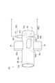
- FIG. 1 is a configuration diagram showing a tubular flame burner according to an embodiment of the present disclosure.
- the tubular flame burner (combustor) 100 of the present embodiment a mixture of air as the oxidizing gas to the ammonia gas (NH 3 gas) as a fuel, a device for combusting ammonia gas.
- NH 3 gas ammonia gas
- the tubular flame burner 100 includes a circular tubular housing 20, two ammonia gas introduction units 30 for introducing ammonia gas inside the housing 20, and two air introduction units for introducing air inside the housing 20. It includes 400 and an ignition unit 500 that ignites the ammonia gas introduced inside the housing 20.
- the housing 20 has a cylindrical portion 20b with both ends open. One end of the housing 20 constitutes an open open end 20a. The open end 20a opens one end of the cylindrical portion 20b to the atmosphere and serves as a combustion gas discharge port, which will be described later.
- a disk-shaped closing wall 60 is provided at the other end of the housing 20. The closing wall 60 closes the other end of the cylindrical portion 20b. The closing wall 60 is fixed to the other end of the cylindrical portion 20b.
- the housing 20 is made of a conductive metal material (for example, stainless steel).
- the ammonia gas introduction section 30 and the air introduction section 400 are an introduction section provided on the outer peripheral surface of the housing 20 at the central portion in the axial direction of the housing 20 or on the closing wall 60 side of the central portion. As shown in FIG. 2, the ammonia gas introduction unit 30 and the air introduction unit 400 are alternately arranged at equal intervals along the circumferential direction of the housing 20.
- the ammonia gas introduction unit 30 introduces ammonia gas into the housing 20 in the tangential direction of the inner peripheral surface 20c of the housing 20. That is, the ammonia gas introduction unit 30 introduces ammonia gas into the housing 20 so as to generate a tubular flow.
- the air introduction unit 400 introduces air into the housing 20 in the tangential direction of the inner peripheral surface 20c of the housing 20.
- the air introduction unit 400 introduces air into the housing 20 so as to generate a tubular flow.
- the ammonia gas introduction unit 30 and the air introduction unit 400 may be formed integrally with the housing 20, or may be formed separately from the housing 20 and fixed to the housing 20.
- the ignition unit 500 turns on / off the discharge electrode terminal 70 arranged inside the housing 20, the igniter 80 that applies a high voltage to the discharge electrode terminal 70 to ignite ammonia gas, and the igniter 80. It has a power supply 90 and a power supply 90.
- the igniter 80 and the power supply 90 constitute a voltage supply unit 140 that supplies a voltage to the discharge electrode terminal 70.
- the discharge electrode terminal 70 is arranged in a region including the inside of the housing 20 on the closed wall 60 side.
- the inside of the housing 20 on the closed wall 60 side refers to a region on the closed wall 60 side of the inside of the housing 20 with respect to the center in the axial direction (longitudinal direction) of the housing 20.
- the discharge electrode terminal 70 is attached to the closing wall 60 via an insulator 110 so as to penetrate the closing wall 60 of the housing 20.
- the insulator 110 is made of an insulating material (for example, ceramic) having pressure resistance and heat resistance.
- the discharge electrode terminal 70 is arranged at the center of the housing 20 in the radial direction inside the housing 20 so as to extend in the axial direction of the housing 20. A part of the discharge electrode terminal 70 is arranged inside the housing 20, and the remaining part of the discharge electrode terminal 70 is arranged outside the housing 20.
- the tip 70a of the discharge electrode terminal 70 is located between the front end 30a of the ammonia gas introduction portion 30 and the front end 400a of the air introduction portion 400 and the closing wall 60 of the housing 20.
- the tip 70a of the discharge electrode terminal 70 is located between the rear end 30b of the ammonia gas introduction portion 30 and the rear end 400b of the air introduction portion 400, and the closing wall 60.
- the tip portion 70a of the discharge electrode terminal 70 is an end portion (the end portion on the open end 20a side) arranged inside the housing 20 among both ends of the discharge electrode terminal 70.
- the front end 30a of the ammonia gas introduction section 30 and the front end 400a of the air introduction section 400 correspond to the ends of the ammonia gas introduction section 30 and the air introduction section 400 on the open end 20a side of the housing 20.
- the rear end 30b of the ammonia gas introduction unit 30 and the rear end 400b of the air introduction unit 400 correspond to the ends of the ammonia gas introduction unit 30 and the air introduction unit 400 on the closed wall 60 side of the housing 20.
- the discharge electrode terminal 70 is connected to the igniter 80 via the electric wire 120.
- the pulse voltage from the igniter 80 is supplied to the discharge electrode terminal 70 via the electric wire 120.
- the discharge electrode terminal 70 functions as a discharge electrode.
- the housing 20 is connected to the ground line (GND line) of the igniter 80 via the electric wire 130. Therefore, the housing 20 is grounded.
- the housing 20 functions as a ground electrode. A space for ammonia gas and air to reach is provided between the discharge electrode terminal 70 and the housing 20.
- the ignition unit 500 ignites ammonia gas by applying a high voltage to the discharge electrode terminal 70 to generate a discharge between the tip 70a of the discharge electrode terminal 70 and the housing 20. At this time, as shown in FIG. 3, plasma is generated between the tip 70a of the discharge electrode terminal 70 and the housing 20 due to the discharge generated between the tip 70a of the discharge electrode terminal 70 and the housing 20. P is formed.
- the ammonia gas introduction unit 30 introduces ammonia gas into the housing 20 in the tangential direction of the inner peripheral surface 20c of the housing 20, and the air introduction unit 400 introduces the housing 20.
- the air introduction unit 400 introduces the housing 20.
- ammonia gas and air are mixed as a tubular flow and swirl and flow inside the housing 20.
- the mixed gas of ammonia gas and air flows inside the housing 20 toward the open end 20a of the housing 20 and flows inside the housing 20 toward the closing wall 60 of the housing 20. It hits the closing wall 60 and flows while changing its direction.
- ammonia gas and air are introduced into the housing 20 in the tangential direction of the inner peripheral surface 20c of the housing 20, the diameter of the housing 20 is larger than the inner diameter (center side) of the housing 20 in the radial direction. Outside the direction, the flow velocity of ammonia gas and air increases.
- ammonia gas ignites inside the housing 20 regardless of the flow velocity and air-fuel ratio of ammonia gas and air. ⁇ It becomes easy to burn.
- the high-temperature combustion gas obtained by burning ammonia gas flows inside the housing 20 toward the open end 20a of the housing 20. Then, the combustion gas is discharged from the open end 20a constituting the discharge port.
- the ammonia gas introduction unit 30 introduces the ammonia gas and air into the circular tubular housing 20 so as to generate a tubular flow
- the ammonia gas and air become tubular. It becomes a flow and flows around the inside of the housing 20.
- the ammonia gas and the air flowing toward the closed wall 60 of the housing 20 hit the closed wall 60 and flow while changing the direction.
- a voltage is supplied to the discharge electrode terminal 70 by the voltage supply unit 140
- a discharge occurs between the tip 70a of the discharge electrode terminal 70 and the grounded housing 20, so that ammonia gas is generated. Ignite and burn, producing a combustion gas containing a tubular flame.
- the combustion gas flows inside the housing 20 toward the open end 20a of the housing 20, and is discharged from the open end 20a.
- the electric discharge occurs in a wide range between the tip portion 70a of the electric discharge electrode terminal 70 and the housing 20.
- the electrode area is substantially increased.
- dielectric breakdown is directed from the discharge electrode terminal 70 toward the housing 20, and discharge paths are formed radially at 360 degrees. Therefore, the structure is less susceptible to local fluctuations in gas flow and the local surface condition of the housing 20, and the ignition stability of ammonia gas is improved. As a result, it is not necessary to locally adjust the flow velocity and the air-fuel ratio of the ammonia gas, unlike the case where the discharge occurs only in a narrow range, for example, only in the vicinity of the tip portion 70a of the discharge electrode terminal 70.
- the discharge electrode terminal 70 is arranged in a region including the inside of the housing 20 on the closed wall 60 side. Therefore, the electric discharge occurs at a position away from the open end 20a of the housing 20 constituting the combustion gas discharge port. As a result, combustion is stabilized inside the housing 20.
- the discharge electrode terminal 70 is attached to the closed wall 60 of the housing 20 via the insulator 110. Therefore, the discharge electrode terminal 70 is less likely to obstruct the tubular flow of ammonia gas and air. Therefore, the ammonia gas and air swirl inside the housing 20 and easily flow, so that the ignition stability of the ammonia gas is further improved.
- the discharge electrode terminal 70 is arranged at the center of the housing 20 in the radial direction inside the housing 20. Therefore, since the distance from the tip 70a of the discharge electrode terminal 70 to the housing 20 is equal over the entire circumference of the housing 20, the discharge is generated between the tip 70a of the discharge electrode terminal 70 and the housing 20. It occurs uniformly in the circumferential direction of the body 20. Therefore, the ignition stability of ammonia gas is further improved.
- the tip portion 70a of the discharge electrode terminal 70 is located between the rear end 30b of the ammonia gas introduction portion 30 and the rear end 400b of the air introduction portion 400 and the closing wall 60. Therefore, the discharge electrode terminal 70 is less likely to obstruct the tubular flow of ammonia gas and air. Therefore, the ammonia gas and the air further swirl inside the housing 20 to facilitate the flow, so that the ignition stability of the ammonia gas is further improved. Further, since the electric discharge is generated at a position sufficiently distant from the open end 20a of the housing 20, combustion becomes more stable inside the housing 20.
- FIG. 4 is a configuration diagram showing a modified example of the tubular flame burner 100 shown in FIG.
- the discharge electrode terminal 70 is attached to the cylindrical portion 20b of the housing 20 via an insulator 110.
- the discharge electrode terminal 70 is attached to the cylindrical portion 20b via the insulator 110 so as to penetrate the cylindrical portion 20b of the housing 20.
- the discharge electrode terminal 70 is arranged so as to extend in the radial direction of the housing 20.
- the tip 70a of the discharge electrode terminal 70 is located at the radial center of the housing 20 between the rear end 30b of the ammonia gas introduction portion 30 and the rear end 400b of the air introduction portion 400 and the closing wall 60. is doing.
- the degree of freedom in arranging the discharge electrode terminals 70 is increased.
- the discharge electrode terminal 70 is arranged at the radial center of the housing 20 inside the housing 20, but is not particularly limited to such a form.
- the discharge electrode terminal 70 may be arranged radially offset from the radial center of the housing 20 inside the housing 20.
- the tip end portion 70a of the discharge electrode terminal 70 is located between the rear end portion 30b of the ammonia gas introduction portion 30 and the closing wall 60, but is particularly limited to such a form. do not have.
- the tip 70a of the discharge electrode terminal 70 may be located between the front end 30a and the rear end 30b of the ammonia gas introduction portion 30.
- the two ammonia gas introduction portions 30 for introducing ammonia gas into the housing 20 in the tangential direction of the inner peripheral surface 20c of the housing 20 and the air inside the housing 20 are introduced into the housing 20.
- the ammonia gas and the air are separately introduced into the housing 20 by the ammonia gas introduction unit 30 and the air introduction unit 400 in the tangential direction of the inner peripheral surface 20c of the housing 20.
- at least one introduction portion for introducing a mixed gas of ammonia gas and air in the tangential direction of the inner peripheral surface 20c of the housing 20 may be provided inside the housing 20. ..
- ammonia gas as fuel is introduced into the housing 20 in the tangential direction of the inner peripheral surface 20c of the housing 20, but the fuel is not particularly limited to ammonia gas and is hydrocarbonized. It may be a fuel gas such as hydrogen gas, methane gas or city gas, or it may be a liquid fuel that vaporizes at a relatively low temperature such as liquid ammonia, kerosene, alcohol or heavy A oil.
- air as an oxidizing gas is introduced into the housing 20 in the tangential direction of the inner peripheral surface 20c of the housing 20, but the oxidizing gas is not particularly limited to air. , Oxygen may be used.
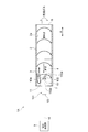
- FIG. 5 is a cross-sectional view showing a combustor according to the second embodiment of the present disclosure.
- the combustor 1 of the present embodiment is a tubular flame burner to produce a combustion gas by burning ammonia gas air is mixed (NH 3 gas).
- Ammonia gas is a fuel.
- Air is an oxidizing gas.
- the combustor 1 includes a circular tubular housing 2, two ammonia gas introduction portions 3 for introducing ammonia gas into the housing 2, and air inside the housing 2. It is provided with two air introduction units 4 for introducing the above, and an ignition unit 5 for igniting the ammonia gas introduced inside the housing 2.
- One end side of the housing 2 is open, and the other end side of the housing 2 is closed.
- One end of the housing 2 constitutes a gas outlet portion 6 from which combustion gas is discharged.
- a closing wall 7 is provided at the other end of the housing 2.
- the housing 2 and the closing wall 7 are made of a conductive metal material (for example, stainless steel). Ammonia gas, air, and combustion gas flow inside the housing 2 in the axial direction (A direction) of the housing 2.
- the ammonia gas introduction unit 3 and the air introduction unit 4 are arranged, for example, on the closed wall 7 side of the central portion in the axial direction of the housing 2. As shown in FIG. 2, the ammonia gas introduction unit 3 and the air introduction unit 4 are alternately arranged at equal intervals along the circumferential direction of the housing 2.
- the ammonia gas introduction unit 3 and the air introduction unit 4 constitute an introduction unit that introduces ammonia gas and air into the housing 2 so as to generate a tubular flow.
- the number of the ammonia gas introduction unit 3 and the air introduction unit 4 is not particularly limited to two, and may be one or three or more. Further, the ammonia gas introduction portion 3 and the air introduction portion 4 may be provided at the central portion in the axial direction of the housing 2, or may be closer to the gas outlet portion 6 than the central portion in the axial direction of the housing 2. It may be provided.
- the ammonia gas introduction unit 3 introduces ammonia gas into the housing 2 in the tangential direction of the inner peripheral surface 2a of the housing 2.
- the air introduction unit 4 introduces air into the housing 2 in the tangential direction of the inner peripheral surface 2a of the housing 2.
- the ammonia gas introduction unit 3 and the air introduction unit 4 may be formed integrally with the housing 2, or may be formed separately from the housing 2 and fixed to the housing 2.
- the ignition unit 5 ignites the ammonia gas introduced inside the housing 2 to generate a combustion gas including a tubular flame.
- the ignition unit 5 has an ignition plug 8 arranged on the other end side (closed wall 7 side) of the housing 2 and a voltage supply unit 9 for supplying a voltage to the spark plug 8.
- the spark plug 8 penetrates the closing wall 7.
- the tip end side portion of the spark plug 8 is arranged inside the housing 2.
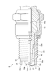
- FIG. 7 is a cross-sectional view of the spark plug 8 on one side.
- FIG. 8 is a schematic front view of the spark plug 8.
- the spark plug 8 is a plug that ignites a mixed gas of ammonia gas and air.
- the spark plug 8 has an insulator 10, a center electrode 11, and a ground electrode 12.
- the spark plug 8 is shown in a simplified manner. Further, in FIGS. 7 and 8, the housing 2 and the closing wall 7 are omitted.
- the insulating insulator 10 has a cylindrical shape.
- the insulating insulator 10 is made of a ceramic such as alumina having excellent insulation, heat resistance and thermal conductivity.
- the insulating insulator 10 is provided with a shaft hole 10a extending in the axial direction of the insulating insulator 10.
- the center electrode 11 is provided at the tip of a round bar-shaped center pole 13 supported by the insulating insulator 10.
- the center pole 13 is supported by the insulating insulator 10 in a state of being inserted into the shaft hole 10a of the insulating insulator 10.
- the center pole 13 is made of, for example, a steel material or the like.
- the center electrode 11 protrudes from the tip surface 10b of the insulating insulator 10. That is, the center electrode 11 is exposed from the tip surface 10b of the insulating insulator 10.
- the center electrode 11 has a circular shape when viewed from the front.
- the center electrode 11 is made of a metal material such as a nickel alloy having excellent heat resistance and corrosion resistance.
- a precious metal chip may be provided on the tip surface 11a of the center electrode 11.
- the ground electrode 12 is integrated with the main metal fitting 14 arranged around the insulator 10.
- the main metal fitting 14 is fixed to the outer peripheral surface of the insulating insulator 10.
- the main metal fitting 14 has a cylindrical shape.
- the cylindrical shape referred to in the present embodiment is not limited to a perfect cylindrical shape, but also includes a substantially cylindrical shape.
- the ground electrode 12 is joined to the tip of the main metal fitting 14 by welding or the like.
- the ground electrode 12 is a cylindrical electrode arranged around the insulator 10.
- the ground electrode 12 is made of a metal material such as a nickel alloy having excellent heat resistance and corrosion resistance.
- the ground electrode 12 is grounded.
- the ground electrode 12 is fixed to the closing wall 7.
- a male screw portion 12a that is screwed with a female screw portion 7a (see FIG. 21) provided on the closing wall 7 is formed.
- the spark plug 8 including the ground electrode 12 is fixed to the closing wall 7.
- the spark plug 8 is fixed to the closing wall 7 so that the center electrode 11 is located at the center of the housing 2 in the radial direction inside the housing 2.
- the main metal fitting 14 is fixed to the housing 2 via the ground electrode 12 and the closing wall 7. At this time, the axial direction of the ground electrode 12 and the main metal fitting 14 coincides with the axial direction of the housing 2 (A direction in FIG. 5). It should be noted that the axial match in the present embodiment is not limited to a perfect match, but also includes an apparent match.
- the ground electrode 12 is arranged outside the center electrode 11 in the radial direction so as not to overlap the center electrode 11 in the axial direction of the ground electrode 12. That is, the ground electrode 12 is arranged at a constant distance in the radial direction from the center electrode 11.
- the tip surface 11a of the center electrode 11 protrudes from the tip surface 12b of the ground electrode 12. That is, the tip surface 11a of the center electrode 11 is located on one end side (gas outlet portion 6 side) of the housing 2 with respect to the tip surface 12b of the ground electrode 12.
- a space S through which ammonia gas and air reach is provided between the center electrode 11 and the ground electrode 12.
- a terminal fitting 15 is provided at the base end of the spark plug 8.
- the terminal fitting 15 is electrically connected to the center pole 13.
- the terminal fitting 15 is exposed from the base end surface 10c of the insulating insulator 10 so as to be located outside the housing 2.
- the voltage supply unit 9 is connected to the terminal fitting 15 of the spark plug 8 via the high voltage cable 16.
- the voltage supply unit 9 applies a high voltage to the center electrode 11 via the high voltage cable 16, the terminal fitting 15, and the center pole 13.
- the center electrode 11 functions as a discharge electrode.
- the ignition unit 5 ignites ammonia gas by applying a high voltage to the center electrode 11 by the voltage supply unit 9 to generate an electric discharge in the space S between the center electrode 11 and the ground electrode 12 in the spark plug 8. Let me. At this time, the electric discharge occurs in the region where the distance between the tip of the center electrode 11 and the ground electrode 12 is the shortest in the space S between the tip of the center electrode 11 and the ground electrode 12.
- the ammonia gas introduction unit 3 introduces ammonia gas into the housing 2 in the tangential direction of the inner peripheral surface 2a of the housing 2, and the air introduction unit 4 introduces the housing 2 into the housing 2.
- the air introduction unit 4 introduces the housing 2 into the housing 2.
- ammonia gas and air are mixed as a tubular flow and swirl and flow inside the housing 2.
- the mixed gas of ammonia gas and air flows inside the housing 2 toward the gas outlet portion 6 and flows inside the housing 2 toward the spark plug 8.
- the voltage supply unit 9 applies a high voltage to the center electrode 11 of the spark plug 8 via the terminal fitting 15 and the center pole 13. Then, as shown in FIG. 9, in the spark plug 8, the discharge P is generated in the space S between the tip end portion of the center electrode 11 and the tip end surface 12b of the ground electrode 12. At this time, the center electrode 11 protrudes from the tip surface 10b of the insulating insulator 10. Therefore, the discharge P generated in the space S between the center electrode 11 and the ground electrode 12 is easily separated from the insulating insulator 10.
- Ammonia gas is ignited and burned by such discharge P to form a tubular flame, so that high-temperature combustion gas is generated.
- the high-temperature combustion gas flows inside the housing 2 toward the gas outlet portion 6 and is discharged from the gas outlet portion 6.
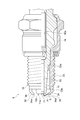
- FIG. 10 is a cross-sectional view showing a combustor as a comparative example.
- the combustor 1A of this comparative example includes a spark plug 101 for an internal combustion engine.
- the spark plug 101 has an insulating insulator 10 and a center electrode 11 similar to the spark plug 8 described above, and a ground electrode 102.
- the ground electrode 102 is integrated with the cylindrical main metal fitting 103 arranged around the insulator 10.
- a male screw portion 103a screwed into a screw hole (not shown) of an internal combustion engine is provided on the outer peripheral surface of the tip end side portion of the main metal fitting 103.
- the ground electrode 102 is joined to the tip of the main metal fitting 103 by welding or the like.
- the ground electrode 102 is bent in an L shape toward the center electrode 11 side (the center side in the radial direction of the ground electrode 102).
- the space between the center electrode 11 and the tip portion 102a of the ground electrode 102 is a discharge gap 104 in which a discharge occurs. Ammonia gas and air flow into the discharge gap 104 in the radial direction of the housing 2.
- ammonia gas and air are introduced into the housing 2 in the tangential direction of the inner peripheral surface 2a of the housing 2, and flow around the inside of the housing 2 as a tubular flow.
- the introduction position of ammonia gas and air is a position near the spark plug 101. Therefore, in the vicinity of the spark plug 101, the flow velocities of ammonia gas and air become faster on the outer side in the radial direction of the housing 2 than on the inner side (center side) in the radial direction of the housing 2.
- a flow (backflow) of ammonia gas and air toward the spark plug 101 occurs in the radial inner region of the housing 2 inside the housing 2 before the ignition of the ammonia gas. ing.
- the ground electrode 102 obstructs the flow of ammonia gas and air to the discharge gap 104. Therefore, it is difficult for ammonia gas and air to flow into the discharge gap 104. Therefore, since the electric discharge generated in the discharge gap 104 does not easily act on the mixed gas of ammonia gas and air, it is difficult to stabilize the operation of igniting the ammonia gas to grow the tubular flame.
- the ground electrode 12 is integrated with the main metal fitting 14 arranged around the insulating insulator 10 and does not overlap with the center electrode 11 in the axial direction of the main metal fitting 14. As described above, it is arranged outside the main metal fitting 14 in the radial direction with respect to the center electrode 11. Therefore, even if the flow of ammonia gas and air toward the spark plug 8 is generated by the tubular flow of ammonia gas and air in the radial inner (center side) region of the housing 2 inside the housing 2, the center electrode The ground electrode 12 prevents the flow of ammonia gas and air into the space S between the ground electrode 12 and the ground electrode 12.
- ammonia gas and air easily flow into the space S between the center electrode 11 and the ground electrode 12, so that the discharge generated in the space S between the center electrode 11 and the ground electrode 12 is a mixture of ammonia gas and air. It becomes easier to act on the gas.
- the flame burns and spreads to the surrounding mixed gas, but the mixed gas flows as a tubular flow toward one end side of the housing 2 in the axial direction of the main metal fitting 14, so that the tubular flame is the axis. Expand in the direction.
- the ground electrode 12 is arranged so as not to overlap with the center electrode 11 in the axial direction of the main metal fitting 14. Therefore, the tubular flame is less likely to be deprived of heat by the ground electrode 12 when the ammonia gas is ignited, and easily expands. As a result, the ignition and combustion operations of ammonia gas are stabilized.
- the ground electrode 12 has a cylindrical shape and is integrated with the main metal fitting 14 so as to be arranged around the insulating insulator 10. Therefore, the existing structure of the ground electrode can be used.
- the tip surface 11a of the center electrode 11 is located on one end side (gas outlet portion 6 side) of the housing 2 with respect to the ground electrode 12. Therefore, ammonia gas and air easily flow from the center electrode 11 side to the ground electrode 12 side. Therefore, ammonia gas and air are more likely to flow into the space S between the center electrode 11 and the ground electrode 12.
- FIG. 11 is a one-sided cross-sectional view showing a spark plug in the combustor according to the third embodiment of the present disclosure.
- FIG. 12 is a schematic front view of the spark plug shown in FIG. In FIGS. 11 and 12, in the combustor 1 of the present embodiment, the spark plug 8 has a center electrode 21 instead of the center electrode 11 of the second embodiment described above.
- the center electrode 21 has a circular shape when viewed from the front.
- the tip surface 21a of the center electrode 21 is located on one end side (gas outlet portion 6 side) of the housing 2 with respect to the tip surface 12b of the ground electrode 12.
- the diameter D1 of the center electrode 21 is larger than the diameter D2 of the tip surface 10b of the insulating insulator 10 and smaller than the diameter D3 (outer diameter) of the tip surface 12b of the ground electrode 12.
- the center electrode 21 has a protruding portion 22 protruding outward in the radial direction of the insulating insulator 10 with respect to the peripheral edge 10d of the front end surface 10b of the insulating insulator 10.
- the side end 22a of the protruding portion 22 is outside the insulating insulator 10 in the radial direction from the peripheral edge 10d of the tip surface 10b of the insulating insulator 10 and inside the ground electrode 12 radially from the outer periphery of the tip end portion of the ground electrode 12. It is located in a certain area.
- the protrusion 22 is provided on the peripheral edge of the center electrode 21 and has an annular shape.
- the protruding portion 22 is provided on the peripheral portion of the circular center electrode 21, and has an annular shape. Therefore, an electric discharge can be generated in the space S between the protrusion 22 and the ground electrode 12 over the entire circumference of the center electrode 21. Further, since the shape of the center electrode 21 is circular, the center electrode 21 can be easily manufactured.
- FIG. 13 is a schematic front view of the spark plug 8 having a modified example of the center electrode 21 shown in FIG.
- the shape of the center electrode 21 is rectangular in front view.
- Protruding portions 22 protruding in the radial direction of the insulating insulator 10 with respect to the peripheral edge 10d of the tip surface 10b of the insulating insulator 10 are provided at both ends of the center electrode 21 in the longitudinal direction.
- the shape of the center electrode 21 has a cross shape when viewed from the front. At each end of the cross of the center electrode 21, projecting portions 22 projecting in the radial direction of the insulating insulator 10 with respect to the peripheral edge 10d of the tip surface 10b of the insulating insulator 10 are provided.
- the shape of the center electrode 21 has a polygonal shape (here, a hexagonal shape) when viewed from the front.
- the peripheral edge of the center electrode 21 is provided with an annular (here, hexagonal annular) protruding portion 22 that protrudes in the radial direction of the insulating insulator 10 with respect to the peripheral edge 10d of the tip surface 10b of the insulating insulator 10.
- FIG. 14 is a one-sided cross-sectional view showing a spark plug in the combustor according to the fourth embodiment of the present disclosure.
- FIG. 15 is a schematic front view of the spark plug shown in FIG. In FIGS. 14 and 15, in the combustor 1 of the present embodiment, the spark plug 8 has a ground electrode 32 instead of the ground electrode 12 of the second embodiment described above.
- the ground electrode 32 has a cylindrical electrode body 33 corresponding to the ground electrode 12 in the second embodiment described above, and two plate-shaped protrusions 34 integrated with the electrode body 33.
- a male screw portion 33a is formed on the outer peripheral surface of the electrode body 33.
- the protrusion 34 projects from the tip surface 33b of the electrode body 33. That is, the tip of the ground electrode 32 is provided with two protrusions 34 protruding toward one end side (gas outlet portion 6 side) of the housing 2.
- the two protrusions 34 are arranged so as to face each other with the center electrode 11 interposed therebetween, for example.
- the tip surface 11a of the center electrode 11 is located on one end side of the housing 2 with respect to the tip surface 34a of the protrusion 34.
- the center electrode 11 of the spark plug 8 when a high voltage is applied to the center electrode 11 of the spark plug 8 via the terminal fitting 15 and the central shaft 13 by the voltage supply unit 9, the center electrode is applied to the spark plug 8.
- a discharge P is generated in the space S between the tip of 11 and the tip of the protrusion 34 of the ground electrode 32, and the ammonia gas ignites and burns.
- FIG. 16 is a one-sided cross-sectional view of the spark plug 8 having a modified example of the ground electrode 32 shown in FIG.
- a bent portion 35 bent in an obtuse angle on the center electrode 11 side is provided on the tip end side of each protrusion 34 of the ground electrode 32. In this case, since the distance between the center electrode 11 and the protrusion 34 is shortened, the discharge P is likely to occur.
- two protrusions 34 are provided at the tip of the ground electrode 32, but the number of protrusions 34 is not particularly limited to two, and may be one. There may be three or more.
- FIG. 17 is a one-sided cross-sectional view showing a spark plug in the combustor according to the fifth embodiment of the present disclosure.
- the spark plug 8 has a ground electrode 32 as in the fourth embodiment described above.
- the tip surface 34a of the protrusion 34 of the ground electrode 32 is located on one end side (gas outlet portion 6 side) of the housing 2 with respect to the tip surface 11a of the center electrode 11.
- the center electrode 11 of the spark plug 8 when a high voltage is applied to the center electrode 11 of the spark plug 8 via the terminal fitting 15 and the central shaft 13 by the voltage supply unit 9, the center electrode is applied to the spark plug 8.
- a discharge P is generated in the space S between the tip of 11 and the side surface 34b on the inside of the protrusion 34 (on the side of the center electrode 11), and the ammonia gas ignites and burns.
- FIG. 18 is a one-sided cross-sectional view showing a spark plug in the combustor according to the sixth embodiment of the present disclosure.
- the spark plug 8 in the combustor 1 of the present embodiment, has a ground electrode 40 instead of the ground electrode 12 of the second embodiment described above.
- the ground electrode 40 is arranged outside the main metal fitting 14 in the radial direction so as not to overlap the center electrode 11 in the axial direction of the main metal fitting 14.
- the ground electrode 40 has a cylindrical portion 41 corresponding to the ground electrode 12 in the second embodiment, the closing wall 7, and a rod-shaped upright portion 43.
- the closing wall 7 constitutes an annular portion that is a part of the ground electrode 40.
- a male screw portion 41a that is screwed with the female screw portion 7a of the closing wall 7 is formed.
- the standing portion 43 is integrated with the closing wall 7.
- the upright portion 43 is provided on the tip surface 7b of the closing wall 7 so as to extend to one end side (gas outlet portion 6 side) of the housing 2.
- the upright portion 43 is arranged outside the cylindrical portion 41 in the radial direction of the closing wall 7.
- the number of the standing portions 43 may be one or a plurality.
- the tip surface 40a of the ground electrode 40 is located on one end side of the housing 2 with respect to the tip surface 11a of the center electrode 11.
- the tip surface 40a of the ground electrode 40 corresponds to the tip surface 43a of the upright portion 43.
- the distance between the center electrode 11 and the peripheral surface 43b of the upright portion 43 is shorter than the distance between the center electrode 11 and the tip surface 41b of the cylindrical portion 41.
- the distance between the center electrode 11 and the peripheral surface 43b of the upright portion 43 is a distance along the radial direction of the main metal fitting 14.
- the center electrode 11 of the spark plug 8 when a high voltage is applied to the center electrode 11 of the spark plug 8 via the terminal fitting 15 and the central shaft 13 by the voltage supply unit 9, the center electrode is applied to the spark plug 8.
- a discharge P is generated in the space S between the tip portion of 11 and the peripheral surface 43b of the upright portion 43, and the ammonia gas ignites and burns.
- FIG. 19 is a front view of the spark plug 8 having a modified example of the ground electrode 40 shown in FIG.
- a bent portion 44 bent in an obtuse angle on the center electrode 11 side is provided on the tip end side portion of the standing portion 43 of the ground electrode 40.
- electric discharge is likely to occur.
- FIG. 20 is a one-sided cross-sectional view showing a spark plug in the combustor according to the seventh embodiment of the present disclosure.
- the spark plug 8 has a ground electrode 45 instead of the ground electrode 40 of the sixth embodiment described above.
- the ground electrode 45 has the above-mentioned cylindrical portion 41 and the closing wall 7, a plurality of (here, two) rod-shaped standing portions 46, and a connecting bar 47.
- the upright portion 46 is provided on the tip surface 7b of the closing wall 7 so as to extend to one end side (gas outlet portion 6 side) of the housing 2.
- the connecting bar 47 is a connecting portion that connects the tips of the vertical portions 46 to each other.
- the tip surface 45a of the ground electrode 45 corresponds to the tip surface 47a of the connecting bar 47.
- the distance R1 between the center electrode 11 and the upright portion 46 is shorter than the distance R2 between the center electrode 11 and the connecting bar 47.
- the distance R1 between the center electrode 11 and the upright portion 46 is a distance along the radial direction of the main metal fitting 14.
- the distance R2 between the center electrode 11 and the connecting bar 47 is a distance along the axial direction of the main metal fitting 14.
- the center electrode 11 of the spark plug 8 when a high voltage is applied to the center electrode 11 of the spark plug 8 via the terminal fitting 15 and the central shaft 13 by the voltage supply unit 9, the center electrode is applied to the spark plug 8.
- a discharge P is generated in the space S between the tip portion of 11 and the peripheral surface 46b of the upright portion 46, and the ammonia gas ignites and burns.
- the strength of the standing portions 46 is increased. Further, when a voltage is supplied to the center electrode 11, a discharge P is generated in the space S between the center electrode 11 and the upright portion 46, and a discharge P is generated in the space between the center electrode 11 and the connecting bar 47. There is no such thing. Further, the discharge energy can be reduced by reducing the heat capacity of the upright portion 46 and the connecting bar 47 as compared with the cylindrical portion 41.
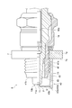
- FIG. 21 is a one-sided cross-sectional view showing a spark plug in the combustor according to the eighth embodiment of the present disclosure.
- the spark plug 8 has a ground electrode 50 instead of the ground electrode 12 of the second embodiment described above.
- the ground electrode 50 is arranged outside the main metal fitting 14 in the radial direction so as not to overlap the center electrode 11 in the axial direction of the main metal fitting 14.
- the ground electrode 50 has a cylindrical portion 41 similar to that of the sixth embodiment described above, and a protrusion 51 provided on the inner peripheral surface 2a of the housing 2.
- the protrusion 51 is provided on the inner peripheral surface 2a of the housing 2 so as to project inward in the radial direction of the housing 2 toward the center electrode 11.
- the protrusion 51 extends from the inner peripheral surface 2a of the housing 2 to the vicinity of the center electrode 11.
- the number of protrusions 51 may be one or a plurality.
- the shape of the protrusion 51 is, for example, a rectangular shape, a fan shape, an annular shape, or the like when viewed in the axial direction of the main metal fitting 14.
- the side surface 51a of the protrusion 51 on the gas outlet 6 side is located on the gas outlet 6 side (one end side of the housing 2) with respect to the tip surface 11a of the center electrode 11.
- the distance between the center electrode 11 and the tip surface 51b of the protrusion 51 is shorter than the distance between the center electrode 11 and the tip surface 41b of the cylindrical portion 41.
- the center electrode 11 of the spark plug 8 when a high voltage is applied to the center electrode 11 of the spark plug 8 via the terminal fitting 15 and the central shaft 13 by the voltage supply unit 9, the center electrode is applied to the spark plug 8.
- a discharge P is generated in the space S between the tip portion 11 and the tip surface 51b of the protrusion 51, and the ammonia gas ignites and burns.
- the present disclosure is not limited to the above embodiments.
- the tip surfaces 11a and 21a of the center electrodes 11 and 21 are located on one end side (gas outlet portion 6 side) of the housing 2 with respect to the tip surface 12b of the ground electrode 12.
- the tip surfaces 11a and 21a of the center electrodes 11 and 21 may be positioned so as to be flush with the tip surface 12b of the ground electrode 12, or other than the housing 2 than the tip surface 12b of the ground electrode 12. It may be located on the end side (closed wall 7 side).
- the tip surface 40a of the ground electrode 40 is located on one end side of the housing 2 with respect to the tip surface 11a of the center electrode 11, but is particularly limited to such a form. do not have.
- the tip surface 40a of the ground electrode 40 may be positioned so as to be flush with the tip surface 11a of the center electrode 11, or located on the other end side of the housing 2 with respect to the tip surface 11a of the center electrode 11. You may be doing it.
- the side surface 51a of the protrusion 51 on the ground electrode 50 on the gas outlet 6 side is on the gas outlet 6 side (one end side of the housing 2) with respect to the tip surface 11a of the center electrode 11. It is located in, but is not particularly limited to such a form.
- the side surface 51a of the protrusion 51 on the gas outlet portion 6 side may be positioned so as to be flush with the tip surface 11a of the center electrode 11, or the housing 2 may be located more than the tip surface 11a of the center electrode 11. It may be located on the other end side.
- the ground electrodes 40, 45, 50 have a cylindrical portion 41 corresponding to the ground electrode 12 in the first embodiment, but such a cylindrical portion. 41 may not be particularly provided.
- the main metal fitting 14 has a cylindrical shape, but the shape of the main metal fitting 14 is not particularly limited to a cylindrical shape, and may be a tubular shape.
- the tubular shape is not limited to a perfect tubular shape, but also includes a substantially tubular shape.
- the ammonia gas introduction unit 3 introduces ammonia gas into the housing 2 in the tangential direction of the inner peripheral surface 2a of the housing 2, and the air introduction unit 4 is introduced inside the housing 2. Air is introduced in the tangential direction of the inner peripheral surface 2a of the housing 2, but the form is not particularly limited to such a form. If the ammonia gas introduction unit 3 introduces ammonia gas into the housing 2 so as to generate a tubular flow, the ammonia gas is introduced into the housing 2 from the tangential direction of the inner peripheral surface 2a of the housing 2. It may be introduced in a staggered manner. If the air introduction unit 4 introduces air into the housing 2 so as to generate a tubular flow, the air is introduced into the housing 2 by shifting the air from the tangential direction of the inner peripheral surface 2a of the housing 2. You may.
- the ammonia gas and the air are separately introduced into the housing 2 by the ammonia gas introduction unit 3 and the air introduction unit 4 so as to generate a tubular flow.
- the housing 2 may be provided with at least one introduction portion for introducing a mixed gas of ammonia gas and air so as to generate a tubular flow.
- ammonia gas as a fuel is introduced so as to generate a tubular flow inside the housing 2, but the fuel is not particularly limited to ammonia gas, and hydrocarbon gas, methane gas, or the like. It may be a fuel gas such as city gas, or a liquid fuel that vaporizes at a relatively low temperature such as liquid ammonia, kerosene, alcohol or heavy A oil.
- air as an oxidizing gas is introduced so as to generate a tubular flow inside the housing 2, but the oxidizing gas is not particularly limited to air and is oxygen. May be good.
Abstract
Description
図1は、本開示の一実施形態に係る管状火炎バーナを示す構成図である。図1において、本実施形態の管状火炎バーナ(燃焼器)100は、燃料であるアンモニアガス(NH3ガス)に酸化性ガスである空気を混合して、アンモニアガスを燃焼させる装置である。 [First Embodiment]
FIG. 1 is a configuration diagram showing a tubular flame burner according to an embodiment of the present disclosure. In Figure 1, the tubular flame burner (combustor) 100 of the present embodiment, a mixture of air as the oxidizing gas to the ammonia gas (NH 3 gas) as a fuel, a device for combusting ammonia gas.
図5は、本開示の第2実施形態に係る燃焼器を示す断面図である。図5において、本実施形態の燃焼器1は、空気が混合されたアンモニアガス(NH3ガス)を燃焼させて燃焼ガスを生成する管状火炎バーナである。アンモニアガスは、燃料である。空気は、酸化性ガスである。 [Second Embodiment]
FIG. 5 is a cross-sectional view showing a combustor according to the second embodiment of the present disclosure. 5, the
図11は、本開示の第3実施形態に係る燃焼器における点火プラグを示す片側断面図である。図12は、図11に示された点火プラグの略正面図である。図11及び図12において、本実施形態の燃焼器1では、点火プラグ8は、上記の第2実施形態における中心電極11に代えて、中心電極21を有している。 [Third Embodiment]
FIG. 11 is a one-sided cross-sectional view showing a spark plug in the combustor according to the third embodiment of the present disclosure. FIG. 12 is a schematic front view of the spark plug shown in FIG. In FIGS. 11 and 12, in the
図14は、本開示の第4実施形態に係る燃焼器における点火プラグを示す片側断面図である。図15は、図14に示された点火プラグの略正面図である。図14及び図15において、本実施形態の燃焼器1では、点火プラグ8は、上記の第2実施形態における接地電極12に代えて、接地電極32を有している。 [Fourth Embodiment]
FIG. 14 is a one-sided cross-sectional view showing a spark plug in the combustor according to the fourth embodiment of the present disclosure. FIG. 15 is a schematic front view of the spark plug shown in FIG. In FIGS. 14 and 15, in the
図17は、本開示の第5実施形態に係る燃焼器における点火プラグを示す片側断面図である。図17において、本実施形態の燃焼器1では、点火プラグ8は、上記の第4実施形態と同様に、接地電極32を有している。接地電極32の突起34の先端面34aは、中心電極11の先端面11aよりも筐体2の一端側(ガス出口部6側)に位置している。 [Fifth Embodiment]
FIG. 17 is a one-sided cross-sectional view showing a spark plug in the combustor according to the fifth embodiment of the present disclosure. In FIG. 17, in the
図18は、本開示の第6実施形態に係る燃焼器における点火プラグを示す片側断面図である。図18において、本実施形態の燃焼器1では、点火プラグ8は、上記の第2実施形態における接地電極12に代えて、接地電極40を有している。接地電極40は、主体金具14の軸方向において中心電極11と重ならないように、中心電極11よりも主体金具14の径方向の外側に配置されている。 [Sixth Embodiment]
FIG. 18 is a one-sided cross-sectional view showing a spark plug in the combustor according to the sixth embodiment of the present disclosure. In FIG. 18, in the
図20は、本開示の第7実施形態に係る燃焼器における点火プラグを示す片側断面図である。図20において、本実施形態の燃焼器1では、点火プラグ8は、上記の第6実施形態における接地電極40に代えて、接地電極45を有している。 [7th Embodiment]
FIG. 20 is a one-sided cross-sectional view showing a spark plug in the combustor according to the seventh embodiment of the present disclosure. In FIG. 20, in the
図21は、本開示の第8実施形態に係る燃焼器における点火プラグを示す片側断面図である。図21において、本実施形態の燃焼器1では、点火プラグ8は、上記の第2実施形態における接地電極12に代えて、接地電極50を有している。接地電極50は、主体金具14の軸方向において中心電極11と重ならないように、中心電極11よりも主体金具14の径方向の外側に配置されている。 [8th Embodiment]
FIG. 21 is a one-sided cross-sectional view showing a spark plug in the combustor according to the eighth embodiment of the present disclosure. In FIG. 21, in the
Claims (15)
- 一端側が開放されると共に他端側が閉塞された円環状の筐体と、
前記筐体の内部に燃料及び酸化性ガスを管状流が発生するように導入する少なくとも1つの導入部と、
前記筐体の内部に導入された前記燃料を着火させる点火ユニットとを備え、
前記点火ユニットは、放電電極と接地電極とを有し、
前記放電電極と前記接地電極との間には、前記燃料及び前記酸化性ガスが到達する空間が設けられている、燃焼器。 An annular housing with one end open and the other end closed,
At least one introduction part that introduces fuel and oxidizing gas into the inside of the housing so as to generate a tubular flow, and
It is provided with an ignition unit for igniting the fuel introduced inside the housing.
The ignition unit has a discharge electrode and a ground electrode, and has a discharge electrode and a ground electrode.
A combustor in which a space for the fuel and the oxidizing gas to reach is provided between the discharge electrode and the ground electrode. - 前記筐体は、一端が開放された開放端を構成すると共に他端に閉塞壁が設けられ、
前記筐体は、接地されることで前記接地電極として機能し、
前記点火ユニットは、前記筐体の前記閉塞壁側の内部を含む領域に配置されて前記放電電極として機能する放電用電極端子と、前記放電用電極端子に電圧を供給する電圧供給部とを有し、前記放電用電極端子の先端部と前記筐体との間で放電を生じさせることで前記燃料を着火させる、請求項1記載の燃焼器。 The housing constitutes an open end with one end open and is provided with a closing wall at the other end.
When the housing is grounded, it functions as the ground electrode.
The ignition unit has a discharge electrode terminal that is arranged in a region including the inside of the housing on the closed wall side and functions as the discharge electrode, and a voltage supply unit that supplies a voltage to the discharge electrode terminal. The combustor according to claim 1, wherein a discharge is generated between the tip of the discharge electrode terminal and the housing to ignite the fuel. - 前記放電用電極端子は、前記閉塞壁に絶縁体を介して取り付けられている請求項2記載の燃焼器。 The combustor according to claim 2, wherein the discharge electrode terminal is attached to the closed wall via an insulator.
- 前記放電用電極端子は、前記筐体の内部における前記筐体の径方向の中心部に配置されている請求項3記載の燃焼器。 The combustor according to claim 3, wherein the discharge electrode terminal is arranged in the radial center of the housing inside the housing.
- 前記放電用電極端子の先端部は、前記導入部の前記閉塞壁側の端と前記閉塞壁との間に位置している請求項2~4の何れか一項記載の燃焼器。 The combustor according to any one of claims 2 to 4, wherein the tip end portion of the discharge electrode terminal is located between the end of the introduction portion on the closed wall side and the closed wall.
- 酸化性ガスが混合された燃料を燃焼させて燃焼ガスを生成する前記燃焼器において、
前記燃料、前記酸化性ガス及び前記燃焼ガスは、前記筐体の軸方向に流れ、
前記点火ユニットは、前記筐体の他端側に配置された点火プラグを有し、前記筐体の内部に導入された前記燃料を着火させて、管状火炎を含む前記燃焼ガスを生成し、
前記点火プラグは、絶縁碍子と、前記絶縁碍子に支持された中軸の先端に設けられて前記放電電極として機能する中心電極と、前記絶縁碍子の周囲に配置された筒状の主体金具と一体化された前記接地電極とを有し、
前記点火ユニットは、前記中心電極に電圧を供給して、前記中心電極と前記接地電極との間の前記空間で放電を生じさせることで、前記燃料を着火させ、
前記中心電極は、前記絶縁碍子の先端面から突出しており、
前記接地電極は、前記主体金具の軸方向において前記中心電極と重ならないように、前記中心電極よりも前記主体金具の径方向の外側に配置されている、請求項1記載の燃焼器。 In the combustor that produces a combustion gas by burning a fuel mixed with an oxidizing gas.
The fuel, the oxidizing gas, and the combustion gas flow in the axial direction of the housing,
The ignition unit has an ignition plug arranged on the other end side of the housing, ignites the fuel introduced inside the housing, and generates the combustion gas containing a tubular flame.
The spark plug is integrated with an insulator, a center electrode provided at the tip of a central shaft supported by the insulator and functioning as the discharge electrode, and a tubular main metal fitting arranged around the insulator. With the ground electrode
The ignition unit ignites the fuel by supplying a voltage to the center electrode to generate an electric discharge in the space between the center electrode and the ground electrode.
The center electrode protrudes from the tip surface of the insulating insulator.
The combustor according to claim 1, wherein the ground electrode is arranged outside the center electrode in the radial direction so as not to overlap the center electrode in the axial direction of the main metal fitting. - 前記接地電極は、円筒状を有すると共に、前記絶縁碍子の周囲に配置されるように前記主体金具と一体化されている請求項6記載の燃焼器。 The combustor according to claim 6, wherein the ground electrode has a cylindrical shape and is integrated with the main metal fitting so as to be arranged around the insulator.
- 前記中心電極の先端は、前記接地電極よりも前記筐体の一端側に位置している請求項7記載の燃焼器。 The combustor according to claim 7, wherein the tip of the center electrode is located on one end side of the housing with respect to the ground electrode.
- 前記中心電極は、前記絶縁碍子の先端面の周縁に対して前記接地電極の径方向に突出した突出部を有し、
前記突出部の側端は、前記絶縁碍子の先端面よりも前記接地電極の径方向の外側で且つ前記接地電極よりも前記接地電極の径方向の内側である領域に位置している請求項7または8記載の燃焼器。 The center electrode has a protruding portion that protrudes in the radial direction of the ground electrode with respect to the peripheral edge of the tip surface of the insulating insulator.
7. The side end of the protruding portion is located in a region outside the tip surface of the insulating insulator in the radial direction of the ground electrode and inside the ground electrode in the radial direction of the ground electrode. Or the combustor according to 8. - 前記中心電極は、円形状を呈し、
前記中心電極の直径は、前記絶縁碍子の先端面の直径よりも大きく且つ前記接地電極の直径よりも小さくなっており、
前記突出部は、前記中心電極の周縁部に設けられ、円環状を呈している請求項9記載の燃焼器。 The center electrode has a circular shape and has a circular shape.
The diameter of the center electrode is larger than the diameter of the tip surface of the insulating insulator and smaller than the diameter of the ground electrode.
The combustor according to claim 9, wherein the protruding portion is provided on the peripheral edge portion of the center electrode and exhibits an annular shape. - 前記接地電極の先端部には、前記筐体の一端側に突出した突起が設けられている請求項7記載の燃焼器。 The combustor according to claim 7, wherein a protrusion protruding from one end side of the housing is provided at the tip of the ground electrode.
- 前記突起の先端は、前記中心電極よりも前記筐体の一端側に位置している請求項11記載の燃焼器。 The combustor according to claim 11, wherein the tip of the protrusion is located on one end side of the housing with respect to the center electrode.
- 前記接地電極は、前記主体金具に取り付けられた環状部と、前記環状部の先端面に前記筐体の一端側に延びるように設けられた立設部とを有する請求項6記載の燃焼器。 The combustor according to claim 6, wherein the ground electrode has an annular portion attached to the main metal fitting and an upright portion provided on the tip end surface of the annular portion so as to extend to one end side of the housing.
- 前記立設部は、前記環状部の先端面に複数設けられており、
前記接地電極は、前記複数の立設部の先端同士を連結する連結部を更に有し、
前記連結部の先端は、前記中心電極よりも前記筐体の一端側に位置しており、
前記中心電極と前記立設部との距離は、前記中心電極と前記連結部との距離よりも短い請求項13記載の燃焼器。 A plurality of the standing portions are provided on the tip surface of the annular portion.
The ground electrode further has a connecting portion for connecting the tips of the plurality of standing portions.
The tip of the connecting portion is located on one end side of the housing with respect to the center electrode.
13. The combustor according to claim 13, wherein the distance between the center electrode and the upright portion is shorter than the distance between the center electrode and the connecting portion. - 前記主体金具は、前記筐体に固定されており、
前記接地電極は、前記筐体の内周面に設けられ、前記中心電極に向かって前記筐体の径方向の内側に突出する突部を有する請求項6記載の燃焼器。 The main metal fitting is fixed to the housing and
The combustor according to claim 6, wherein the ground electrode is provided on the inner peripheral surface of the housing and has a protrusion protruding inward in the radial direction of the housing toward the center electrode.
Priority Applications (4)
| Application Number | Priority Date | Filing Date | Title |
|---|---|---|---|
| US17/794,650 US20230086672A1 (en) | 2020-02-05 | 2021-01-13 | Combustor |
| CN202180007947.3A CN114930084B (en) | 2020-02-05 | 2021-01-13 | Burner with a burner body |
| AU2021217837A AU2021217837B2 (en) | 2020-02-05 | 2021-01-13 | Combustor |
| JP2021575679A JP7388642B2 (en) | 2020-02-05 | 2021-01-13 | combustor |
Applications Claiming Priority (4)
| Application Number | Priority Date | Filing Date | Title |
|---|---|---|---|
| JP2020018145 | 2020-02-05 | ||
| JP2020-018145 | 2020-02-05 | ||
| JP2020165666 | 2020-09-30 | ||
| JP2020-165666 | 2020-09-30 |
Publications (1)
| Publication Number | Publication Date |
|---|---|
| WO2021157302A1 true WO2021157302A1 (en) | 2021-08-12 |
Family
ID=77200050
Family Applications (1)
| Application Number | Title | Priority Date | Filing Date |
|---|---|---|---|
| PCT/JP2021/000841 WO2021157302A1 (en) | 2020-02-05 | 2021-01-13 | Combustor |
Country Status (5)
| Country | Link |
|---|---|
| US (1) | US20230086672A1 (en) |
| JP (1) | JP7388642B2 (en) |
| CN (1) | CN114930084B (en) |
| AU (1) | AU2021217837B2 (en) |
| WO (1) | WO2021157302A1 (en) |
Cited By (2)
| Publication number | Priority date | Publication date | Assignee | Title |
|---|---|---|---|---|
| JP7384941B2 (en) | 2022-01-14 | 2023-11-21 | 中外炉工業株式会社 | Burna |
| WO2023234110A1 (en) * | 2022-05-31 | 2023-12-07 | 株式会社豊田自動織機 | Combustor and ammonia engine system |
Citations (7)
| Publication number | Priority date | Publication date | Assignee | Title |
|---|---|---|---|---|
| JPS519134U (en) * | 1974-07-09 | 1976-01-23 | ||
| JPS5224287Y2 (en) * | 1972-11-13 | 1977-06-02 | ||
| JPS6132979A (en) * | 1984-07-25 | 1986-02-15 | 株式会社デンソー | Small-sized spark plug |
| JPS63184372U (en) * | 1987-05-15 | 1988-11-28 | ||
| JPH07288170A (en) * | 1994-04-19 | 1995-10-31 | Ngk Spark Plug Co Ltd | Spark pug for internal combustion engine |
| JP2004093114A (en) * | 2002-08-15 | 2004-03-25 | Jfe Steel Kk | Tubular flame burner |
| KR101174094B1 (en) * | 2011-10-19 | 2012-08-14 | 한국기계연구원 | Plasma burner |
Family Cites Families (7)
| Publication number | Priority date | Publication date | Assignee | Title |
|---|---|---|---|---|
| CN2126939Y (en) * | 1992-07-08 | 1993-02-10 | 门晓光 | Oil-saving spark plug |
| US6080029A (en) * | 1999-08-05 | 2000-06-27 | Halo, Inc. | Method of manufacturing a spark plug with ground electrode concentrically disposed to a central electrode |
| JP2004069265A (en) * | 2002-08-09 | 2004-03-04 | Jfe Steel Kk | Sintering ore ignition furnace |
| CN101004260B (en) * | 2002-08-09 | 2010-10-06 | 杰富意钢铁株式会社 | Tubular flame burner and combustion control method thereof |
| CN102047512A (en) * | 2007-11-02 | 2011-05-04 | 霍尼韦尔国际公司 | Spark plug casing and spark plug having the spark plug casing |
| CN202217911U (en) * | 2011-09-23 | 2012-05-09 | 柳孟柱 | Spark plug |
| CA2859488A1 (en) * | 2014-08-15 | 2016-02-15 | Mark Farrell | Improved spark plug |
-
2021
- 2021-01-13 US US17/794,650 patent/US20230086672A1/en active Pending
- 2021-01-13 JP JP2021575679A patent/JP7388642B2/en active Active
- 2021-01-13 WO PCT/JP2021/000841 patent/WO2021157302A1/en active Application Filing
- 2021-01-13 AU AU2021217837A patent/AU2021217837B2/en active Active
- 2021-01-13 CN CN202180007947.3A patent/CN114930084B/en active Active
Patent Citations (7)
| Publication number | Priority date | Publication date | Assignee | Title |
|---|---|---|---|---|
| JPS5224287Y2 (en) * | 1972-11-13 | 1977-06-02 | ||
| JPS519134U (en) * | 1974-07-09 | 1976-01-23 | ||
| JPS6132979A (en) * | 1984-07-25 | 1986-02-15 | 株式会社デンソー | Small-sized spark plug |
| JPS63184372U (en) * | 1987-05-15 | 1988-11-28 | ||
| JPH07288170A (en) * | 1994-04-19 | 1995-10-31 | Ngk Spark Plug Co Ltd | Spark pug for internal combustion engine |
| JP2004093114A (en) * | 2002-08-15 | 2004-03-25 | Jfe Steel Kk | Tubular flame burner |
| KR101174094B1 (en) * | 2011-10-19 | 2012-08-14 | 한국기계연구원 | Plasma burner |
Cited By (2)
| Publication number | Priority date | Publication date | Assignee | Title |
|---|---|---|---|---|
| JP7384941B2 (en) | 2022-01-14 | 2023-11-21 | 中外炉工業株式会社 | Burna |
| WO2023234110A1 (en) * | 2022-05-31 | 2023-12-07 | 株式会社豊田自動織機 | Combustor and ammonia engine system |
Also Published As
| Publication number | Publication date |
|---|---|
| CN114930084B (en) | 2023-12-05 |
| JPWO2021157302A1 (en) | 2021-08-12 |
| JP7388642B2 (en) | 2023-11-29 |
| CN114930084A (en) | 2022-08-19 |
| AU2021217837A1 (en) | 2022-07-14 |
| US20230086672A1 (en) | 2023-03-23 |
| AU2021217837B2 (en) | 2023-12-21 |
Similar Documents
| Publication | Publication Date | Title |
|---|---|---|
| WO2021157302A1 (en) | Combustor | |
| US7452513B2 (en) | Triple helical flow vortex reactor | |
| US7741762B2 (en) | Dual-spark pre-chambered spark igniter | |
| US9951743B2 (en) | Plasma ignition device | |
| CN102913365A (en) | Annular discharge based transient state plasma igniter | |
| CA1166144A (en) | Ignition method and system for internal burner type ultra-high velocity flame jet apparatus | |
| JPS62145678A (en) | Spark plug with combination of surface and air spark paths | |
| JP2011034953A (en) | Plasma igniter, and ignition device of internal combustion engine | |
| JP2003157952A (en) | Ignition plug and combustion chamber device | |
| JP3175588B2 (en) | Fuel discharge structure | |
| JP2005079097A (en) | Spark plug | |
| WO1996014540A1 (en) | Pilot burner and pilot burner gas nozzle utilizing the same | |
| CN102074897A (en) | Step type spark plug | |
| US20210135433A1 (en) | Prechamber spark plug | |
| KR100292019B1 (en) | Spark Plug System | |
| JPS593508Y2 (en) | internal combustion engine spark plug | |
| WO2019205908A1 (en) | Spark plug, engine, ignition method for spark plug and ignition method for engine | |
| JPH1068510A (en) | Fuel injection gun | |
| JP3886415B2 (en) | Spark plug and burner | |
| CN219300801U (en) | Electrode needle for generating high-voltage arc | |
| CN2422547Y (en) | Industrial electronic igniter | |
| JP7430106B2 (en) | spark plug | |
| CN217692091U (en) | Spark plug, engine and car | |
| KR100224368B1 (en) | Spark plug | |
| RU1777640C (en) | Igniter |
Legal Events
| Date | Code | Title | Description |
|---|---|---|---|
| 121 | Ep: the epo has been informed by wipo that ep was designated in this application |
Ref document number: 21751014 Country of ref document: EP Kind code of ref document: A1 |
|
| ENP | Entry into the national phase |
Ref document number: 2021217837 Country of ref document: AU Date of ref document: 20210113 Kind code of ref document: A |
|
| ENP | Entry into the national phase |
Ref document number: 2021575679 Country of ref document: JP Kind code of ref document: A |
|
| NENP | Non-entry into the national phase |
Ref country code: DE |
|
| 122 | Ep: pct application non-entry in european phase |
Ref document number: 21751014 Country of ref document: EP Kind code of ref document: A1 |