WO2021156914A1 - Attention direction determination device and attention direction determination method - Google Patents
Attention direction determination device and attention direction determination method Download PDFInfo
- Publication number
- WO2021156914A1 WO2021156914A1 PCT/JP2020/003925 JP2020003925W WO2021156914A1 WO 2021156914 A1 WO2021156914 A1 WO 2021156914A1 JP 2020003925 W JP2020003925 W JP 2020003925W WO 2021156914 A1 WO2021156914 A1 WO 2021156914A1
- Authority
- WO
- WIPO (PCT)
- Prior art keywords
- occupant
- unit
- face orientation
- attention
- estimation unit
- Prior art date
Links
Images


Classifications
-
- G—PHYSICS
- G06—COMPUTING; CALCULATING OR COUNTING
- G06T—IMAGE DATA PROCESSING OR GENERATION, IN GENERAL
- G06T7/00—Image analysis
- G06T7/70—Determining position or orientation of objects or cameras
-
- G—PHYSICS
- G06—COMPUTING; CALCULATING OR COUNTING
- G06V—IMAGE OR VIDEO RECOGNITION OR UNDERSTANDING
- G06V20/00—Scenes; Scene-specific elements
- G06V20/50—Context or environment of the image
- G06V20/59—Context or environment of the image inside of a vehicle, e.g. relating to seat occupancy, driver state or inner lighting conditions
-
- G—PHYSICS
- G06—COMPUTING; CALCULATING OR COUNTING
- G06V—IMAGE OR VIDEO RECOGNITION OR UNDERSTANDING
- G06V40/00—Recognition of biometric, human-related or animal-related patterns in image or video data
- G06V40/10—Human or animal bodies, e.g. vehicle occupants or pedestrians; Body parts, e.g. hands
- G06V40/103—Static body considered as a whole, e.g. static pedestrian or occupant recognition
-
- G—PHYSICS
- G06—COMPUTING; CALCULATING OR COUNTING
- G06V—IMAGE OR VIDEO RECOGNITION OR UNDERSTANDING
- G06V40/00—Recognition of biometric, human-related or animal-related patterns in image or video data
- G06V40/10—Human or animal bodies, e.g. vehicle occupants or pedestrians; Body parts, e.g. hands
- G06V40/18—Eye characteristics, e.g. of the iris
Definitions
- the skeleton estimation unit 5 estimates that the occupant's hand extends toward the adjacent seat. In the example shown in FIG. 8, when the occupant's hand is detected in the skeleton detection area B, the skeleton estimation unit 5 estimates that the occupant's hand extends toward the rear seat. In the example shown in FIG. 8, when the occupant's hand is detected in the skeleton detection area C, the skeleton estimation unit 5 estimates that the occupant's hand extends in the direction of the doorknob.
- the face orientation detection unit 6 may be configured to detect the visual field or the line of sight of the occupant from the feature points estimated by the face feature point estimation unit 2. That is, the face orientation detection unit 6 calculates the occupant's face orientation angle and the occupant's field of view or line of sight based on the occupant's face feature points estimated by the face feature point estimation unit 2, and calculates the occupant's face orientation.
- the configuration may be such that the face orientation of the occupant is detected based on the angle and the occupant's field of view or line of sight.
- the face orientation detection unit 6 determines that the occupant is facing the adjacent seat direction and determines the occupant's line-of-sight direction angle. If the considered face-facing angle exceeds the predetermined angle ⁇ , it is determined that the occupant is facing the rear seat direction. Further, the face orientation detection unit 6 determines that the occupant is facing the door knob direction when the face orientation angle considering the occupant's line-of-sight direction angle is 0 ° to a predetermined angle ⁇ or less, and determines the occupant's line-of-sight direction angle. If the considered face-facing angle exceeds the predetermined angle ⁇ , it is determined that the occupant is facing the rear seat direction.
- step S105 the skeleton estimation unit 5 estimates the skeleton of the occupant based on the relative position of the occupant's head estimated by the head position estimation unit 3 and the size of each part estimated by the site estimation unit 4. ..
- step S106 the skeleton estimation unit 5 determines whether the estimated skeleton is detected in the skeleton detection area, and estimates the direction in which the occupant's hand is extended.
- the direction in which the occupant's hand is extended is the door knob direction estimated by the skeleton estimation unit, and the occupant's face detected by the face orientation detection unit.
- the direction is the door knob direction, it is determined that the direction in which the occupant is paying attention is the door knob direction.
- Embodiment 2 The configuration of the caution direction determination device 200 according to the second embodiment of the present disclosure will be described. The same or corresponding configurations as those in the first embodiment will be omitted, and only the parts having different configurations will be described.
- the seating information acquisition unit 21 acquires the seating information of the occupant in the vehicle from the image of the occupant in the vehicle taken by the camera 9.
- the seating information is information indicating which seat in the vehicle the occupant is seated in.
- the acquisition of the seating information of the occupant in the vehicle by the seating information acquisition unit 21 is not limited to the configuration acquired from the image of the occupant in the vehicle taken by the camera 9.
- the seating information acquisition unit 21 may be configured to acquire the seating information of the occupant in the vehicle from the seating sensor.
- the attention direction determination unit 7 acquires the seating information, the direction in which the occupant's hand is extended estimated by the skeleton estimation unit 5, the occupant's face orientation detected by the face orientation detection unit 6, and the seating information.
- the direction in which the occupant is paying attention is determined based on at least one information of the seating information acquired by the unit 21 or the vehicle information acquired by the vehicle information acquisition unit 22.
- the attention direction determination unit 7 determines the direction in which the occupant's hand is extended estimated by the skeleton estimation unit 5, the occupant's face orientation detected by the face orientation detection unit 6, and the seating acquired by the seating information acquisition unit 21. An example of determination in the case of determining the direction in which the occupant is paying attention based on the information will be described.
- the attention direction determination unit 7 determines the direction in which the occupant's hand is extended estimated by the skeleton estimation unit 5, the occupant's face orientation detected by the face orientation detection unit 6, and the vehicle acquired by the vehicle information acquisition unit 22. An example of determination in the case of determining the direction in which the occupant is paying attention based on the information will be described.
- the face orientation detection unit 6 uses a predetermined angle value or a skeleton used when detecting the face orientation of the occupant.
- the estimation unit 5 may be configured to change the size of each skeleton detection area used when estimating the extending direction of the occupant's hand. For example, when the vehicle information acquired by the vehicle information acquisition unit 22 indicates that the vehicle gear is parking or the ignition is off, the skeleton estimation unit 5 uses each skeleton detection area when the vehicle is running. It may be configured to be larger than.
- the control unit 10 When the attention direction determination unit 7 does not use the seating information and the vehicle information when determining the direction in which the occupant is paying attention, the control unit 10 outputs the determination result output from the determination result output unit 8.
- the vehicle-mounted device or the like may be controlled based on at least one piece of seating information acquired by the seating information acquisition unit 21 or vehicle information acquired by the vehicle information acquisition unit 22.
- control unit 10 controls the in-vehicle device or the like based on the determination result output from the determination result output unit 8 and the seating information acquired by the seating information acquisition unit 21. An embodiment in the case of performing the above will be described.
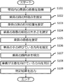
- the control unit 10 When the control unit 10 receives the determination result that the direction in which the occupant is paying attention is the direction of the next seat, the control unit 10 acquires the next seat seating information from the seating information acquired by the seating information acquisition unit 21.
- the control unit 10 When the seating information acquired by the control unit 10 is information indicating that the occupant is not seated in the seat next to the occupant to be detected, the control unit 10 is for turning on the lighting for illuminating the occupant next to the occupant to be detected. Take control.
- the seating information acquired by the control unit 10 is information indicating that the occupant is seated in the seat next to the occupant to be detected, the control unit 10 turns on the light illuminating the occupant next to the occupant to be detected. No control for
- the control unit 10 When the control unit 10 receives the determination result that the direction in which the occupant is paying attention is the rear seat direction, the control unit 10 acquires the rear seat seating information from the seating information acquired by the seating information acquisition unit 21. When the seating information acquired by the control unit 10 is information indicating that the occupant is not seated in the rear seat of the occupant to be detected, the control unit 10 turns on the light illuminating the rear seat of the occupant to be detected. Control for. On the other hand, when the seating information acquired by the control unit 10 is information indicating that the occupant is seated in the rear seat of the occupant to be detected, the control unit 10 illuminates the rear seat of the occupant to be detected. No control is performed to turn it on.
- control unit 10 controls the in-vehicle device or the like based on the determination result output from the determination result output unit 8 and the vehicle information acquired by the vehicle information acquisition unit 22. An embodiment in the case of performing the above will be described.
- the attention direction determination unit 7 does not use the seating information and the vehicle information when determining the direction in which the occupant is paying attention, and the attention direction determination unit 7 determines the direction in which the attention is directed.
- the control unit 10 corresponds to the determination result when the vehicle information acquired by the vehicle information acquisition unit 22 indicates that the vehicle is stopped. It may be configured to control the equipment or the like. That is, the control unit 10 is a occupant whose attention direction is determined by the attention direction determination unit 7 in the driver's seat, and the vehicle information acquired by the vehicle information acquisition unit 22 is the vehicle. If it indicates that the vehicle is not stopped, the vehicle-mounted device or the like may not be controlled.
- FIG. 13 is a flowchart showing an example of the operation of the caution direction determination device 200 shown in FIG. Note that steps S201 to S207 in FIG. 13 correspond to steps S101 to S107 in FIG. 11, and step S211 in FIG. 13 corresponds to step S109 in FIG. 11, so the description thereof is omitted here. Hereinafter, steps S208 to S210 will be described.
- step S208 the seating information acquisition unit 21 acquires the seating information of the occupant in the vehicle.
- step S209 the vehicle information acquisition unit 22 acquires vehicle information.
- the attention direction determination device has a seating information acquisition unit that acquires seating information of the occupant in the vehicle, and the attention direction determination unit extends the occupant's hand estimated by the skeleton estimation unit.
- the direction in which the occupant is paying attention is determined based on the direction, the occupant's face orientation detected by the face orientation detection unit, and the seating information acquired by the seating information acquisition unit.
- the attention direction determination device has a vehicle information acquisition unit that acquires vehicle information of the vehicle, and the attention direction determination unit is a direction in which the occupant's hand is extended as estimated by the skeleton estimation unit.
- the direction in which the occupant is paying attention is determined based on the occupant's face orientation detected by the face orientation detection unit and the vehicle information acquired by the vehicle information acquisition unit.
- the direction in which the occupant's hand is extended is the direction of the adjacent seat estimated by the skeleton estimation unit, and the occupant's face detected by the face orientation detection unit.
- the direction is the direction of the next seat and the seating information acquired by the seating information acquisition unit indicates that the occupant is not seated in the next seat, it is determined that the direction in which the occupant is paying attention is the direction of the next seat.
- the direction in which the occupant's hand is extended as estimated by the skeleton estimation unit is the rear seat direction
- the occupant's face orientation detection unit detects it.
- the face direction is the rear seat direction and the seating information acquired by the seating information acquisition unit indicates that the occupant is not seated in the rear seat
- the direction in which the occupant is paying attention is the rear seat direction. judge.
- the attention direction determination device 200 can determine the direction in which the occupant is paying attention. Further, the attention direction determination device 200 according to the second embodiment determines the direction in which the occupants are paying attention in consideration of the information regarding a plurality of occupants by acquiring the seating information, so that the attention direction is erroneously determined. Can be reduced. Further, since the attention direction determination device 200 according to the second embodiment determines the direction in which the occupant is paying attention in consideration of the state of the vehicle by acquiring the vehicle information, the erroneous determination of the attention direction is reduced. can do.
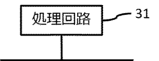
- Each function of the determination result output unit 8, the seating information acquisition unit 21, and the vehicle information acquisition unit 22 is realized by the processing circuit. That is, the attention direction determination devices 100 and 200 acquire the image of the occupant in the vehicle taken by the camera, estimate the feature points of the occupant's face, estimate the relative position of the occupant's head with respect to the camera, and image.
- the processing circuit 31 is, for example, a single circuit, a composite circuit, a programmed processor, a parallel programmed processor, or an ASIC (Application Specific Integrated Circuit). , FPGA (Field Processor Gate Array), or a combination thereof.
- Each function of 21 and the vehicle information acquisition unit 22 may be realized by the processing circuit 31, or each function may be collectively realized by one processing circuit 31.
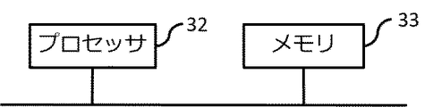
- the processing circuit 31 is the processor 32 shown in FIG. 15, the image acquisition unit 1, the face feature point estimation unit 2, the head position estimation unit 3, the site estimation unit 4, the skeleton estimation unit 5, the face orientation detection unit 6, and the attention direction.
- Each function of the determination unit 7, the determination result output unit 8, the seating information acquisition unit 21, and the vehicle information acquisition unit 22 is realized by software, firmware, or a combination of software and firmware.
- the software or firmware is written as a program and stored in the memory 33.
- the processor 32 realizes each function by reading and executing the program recorded in the memory 33. That is, the attention direction determination devices 100 and 200 are programs in which each step from step S101 to step S109 shown in FIG. 11 or each step from step S201 to step S211 shown in FIG. 13 is executed as a result.
- a memory 33 for storing the above is provided. Further, these programs include an image acquisition unit 1, a face feature point estimation unit 2, a head position estimation unit 3, a site estimation unit 4, a skeleton estimation unit 5, a face orientation detection unit 6, a attention direction determination unit 7, and a determination result output. It can also be said that the computer is made to execute the procedure or method of the unit 8, the seating information acquisition unit 21, and the vehicle information acquisition unit 22.
- the memory is, for example, a RAM (Random Access Memory), a ROM (Read Only Memory), a flash memory, an EPROM (Erasable Programmable Read Only Memory), an EPROM (Electrically Memory) It may be a semiconductor memory, a magnetic disk, a flexible disk, an optical disk, a compact disk, a DVD (Digital Versaille Disc), or any other storage medium that will be used in the future.
- RAM Random Access Memory
- ROM Read Only Memory
- flash memory an EPROM (Erasable Programmable Read Only Memory)
- EPROM Electrically Memory
- It may be a semiconductor memory, a magnetic disk, a flexible disk, an optical disk, a compact disk, a DVD (Digital Versaille Disc), or any other storage medium that will be used in the future.
- some functions may be realized by dedicated hardware, and other functions may be realized by software or firmware.
- the processing circuit can realize each of the above-mentioned functions by hardware, software, firmware, or a combination thereof.
- the caution direction determination device described above is an appropriate combination of not only an in-vehicle navigation device, that is, a car navigation device, but also a PND (Portable Navigation Device) that can be mounted on the vehicle, a server provided outside the vehicle, and the like. It can also be applied to a navigation device constructed as a system or a device other than the navigation device. Even if each function of the attention direction determination device is distributed and arranged in each function for constructing the system, the same effect as that of the above-described embodiment can be obtained.
- each embodiment can be freely combined, and each embodiment can be appropriately modified or omitted within the scope of the disclosure.
Landscapes
- Engineering & Computer Science (AREA)
- Physics & Mathematics (AREA)
- General Physics & Mathematics (AREA)
- Theoretical Computer Science (AREA)
- Multimedia (AREA)
- Human Computer Interaction (AREA)
- Health & Medical Sciences (AREA)
- General Health & Medical Sciences (AREA)
- Ophthalmology & Optometry (AREA)
- Computer Vision & Pattern Recognition (AREA)
- Image Processing (AREA)
- Image Analysis (AREA)
Abstract
A purpose of the present invention is to provide an attention direction determination device and an attention direction determination method that determine the direction in which the attention of an occupant is directed. This attention direction determination device comprises: an image acquisition unit that acquires an image of an occupant in a vehicle, said image having been captured by a camera; a face characteristic point estimation unit that estimates a characteristic point of the face of the occupant, on the basis of the image that was acquired by the image acquisition unit; a skeleton estimation unit that estimates the direction in which a hand of the occupant is extending, on the basis of the image that was acquired by the image acquisition unit; a face orientation detection unit that detects the face orientation of the occupant, on the basis of the face characteristic point that was estimated by the face characteristic point estimation unit; and an attention direction determination unit that determines the direction in which the attention of the occupant attention is directed, on the basis of the direction in which the hand of the occupant is extended that was estimated by the skeleton estimation unit and the face orientation of the occupant that was detected by the face orientation detection unit.
Description
本開示は、車両内の乗員が注意を向けている方向を判定する注意方向判定装置および注意方向判定方法に関する。
The present disclosure relates to a caution direction determination device and a caution direction determination method for determining a direction in which an occupant in a vehicle is paying attention.
従来、車両内に搭載されたカメラによって取得された画像から、車両内の乗員の人体的特徴点を検出し、検出した人体的特徴点の位置変化に基づき、車両内の乗員の行動を予測する技術が開示されている。(例えば、特許文献1参照)
Conventionally, the human body feature points of the occupants in the vehicle are detected from the images acquired by the camera mounted in the vehicle, and the behavior of the occupants in the vehicle is predicted based on the position change of the detected human feature points. The technology is disclosed. (See, for example, Patent Document 1)
従来技術では、人体的特徴点の位置変化から車両内の乗員の行動を予測するが、乗員が注意を向けている方向を推定していないため、乗員が注意を向けている方向とは関係のない行動を予測するという問題がある。例えば、従来技術では、乗員が車載機器の方向に注意を向けていない状態で着座姿勢を変えた場合であっても、人体的特徴点の位置変化から、乗員の行動は車載機器を操作する行動であると予測するという問題がある。
In the conventional technology, the behavior of the occupant in the vehicle is predicted from the position change of the human feature point, but since the direction in which the occupant is paying attention is not estimated, it is related to the direction in which the occupant is paying attention. There is the problem of predicting no behavior. For example, in the prior art, even when the occupant changes the sitting posture without paying attention to the direction of the in-vehicle device, the occupant's behavior is the behavior of operating the in-vehicle device due to the change in the position of the human body feature point. There is a problem of predicting that.
本開示は、上記のような課題を解決するためになされたもので、乗員が注意を向けている方向を判定する注意方向判定装置および注意方向判定方法を提供することを目的とする。
The present disclosure has been made to solve the above-mentioned problems, and an object of the present disclosure is to provide a caution direction determination device and a caution direction determination method for determining a direction in which an occupant is paying attention.
本開示に係る注意方向判定装置は、カメラが撮影した車両内の乗員の画像を取得する画像取得部と、画像取得部が取得した画像に基づいて、乗員の顔の特徴点を推定する顔特徴点推定部と、画像取得部が取得した画像に基づいて、乗員の手の伸びている方向を推定する骨格推定部と、顔特徴点推定部が推定した顔の特徴点に基づいて、乗員の顔向きを検出する顔向き検出部と、骨格推定部が推定した乗員の手の伸びている方向と、顔向き検出部が検出した乗員の顔向きとに基づいて、乗員が注意を向けている方向を判定する注意方向判定部と、を備える。
The caution direction determination device according to the present disclosure is an image acquisition unit that acquires an image of the occupant in the vehicle taken by the camera, and a facial feature that estimates the feature points of the occupant's face based on the image acquired by the image acquisition unit. Based on the point estimation unit, the skeleton estimation unit that estimates the direction in which the occupant's hand is extending based on the image acquired by the image acquisition unit, and the facial feature points estimated by the facial feature point estimation unit, the occupant's The occupant is paying attention based on the face orientation detection unit that detects the face orientation, the occupant's hand extension direction estimated by the skeleton estimation unit, and the occupant's face orientation detected by the face orientation detection unit. A caution direction determining unit for determining a direction is provided.
本開示に係る注意方向判定方法は、カメラが撮影した車両内の乗員の画像を取得するステップと、画像に基づいて、乗員の顔の特徴点を推定するステップと、画像に基づいて、乗員の手の伸びている方向を推定するステップと、顔の特徴点に基づいて、乗員の顔向きを検出するステップと、乗員の手の伸びている方向と、乗員の顔向きとに基づいて、乗員が注意を向けている方向を判定するステップと、を有する。
The attention direction determination method according to the present disclosure includes a step of acquiring an image of the occupant in the vehicle taken by the camera, a step of estimating a feature point of the occupant's face based on the image, and a step of estimating the occupant's face based on the image. An occupant based on a step of estimating the direction in which the hand is extended, a step of detecting the occupant's face orientation based on facial feature points, and an occupant's hand extension direction and the occupant's face orientation. Has a step of determining the direction in which the attention is directed.
本開示に係る注意方向判定装置によれば、乗員が注意を向けている方向を判定することができる。
According to the attention direction determination device according to the present disclosure, it is possible to determine the direction in which the occupant is paying attention.
本開示に係る注意方向判定方法によれば、乗員が注意を向けている方向を判定することができる。
According to the attention direction determination method according to the present disclosure, it is possible to determine the direction in which the occupant is paying attention.
以下、本開示をより詳細に説明するために、本開示を実施するための形態について、添付の図面に従って説明する。なお、以下に示す実施の形態は一例であり、これらの実施の形態によって本開示が限定されるものではない。
Hereinafter, in order to explain the present disclosure in more detail, a mode for carrying out the present disclosure will be described with reference to the attached drawings. The embodiments shown below are examples, and the present disclosure is not limited to these embodiments.
実施の形態1.
図1は、本実施の形態による注意方向判定装置100の構成の一例を示すブロック図である。また、注意方向判定装置100は、車両内に搭載されているものとする。Embodiment 1.
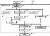
FIG. 1 is a block diagram showing an example of the configuration of the attentiondirection determination device 100 according to the present embodiment. Further, it is assumed that the caution direction determination device 100 is mounted in the vehicle.
図1は、本実施の形態による注意方向判定装置100の構成の一例を示すブロック図である。また、注意方向判定装置100は、車両内に搭載されているものとする。
FIG. 1 is a block diagram showing an example of the configuration of the attention
図1に示すように、注意方向判定装置100は、画像取得部1と、顔特徴点推定部2と、頭位置推定部3と、部位推定部4と、骨格推定部5と、顔向き検出部6と、注意方向判定部7と判定結果出力部8とを備えている。また、画像取得部1は、カメラ9に接続されている。カメラ9は、車両内に搭載されている。判定結果出力部8は、制御部10に接続されている。制御部10は、判定結果出力部8が出力した判定結果を受信し、判定結果に基づいて車載機器等の制御を行う。ここで、車載機器とは、例えば、車内の照明機器、ナビゲーション装置または音響機器等である。
As shown in FIG. 1, the attention direction determination device 100 includes an image acquisition unit 1, a face feature point estimation unit 2, a head position estimation unit 3, a site estimation unit 4, a skeleton estimation unit 5, and a face orientation detection. A unit 6, a caution direction determination unit 7, and a determination result output unit 8 are provided. Further, the image acquisition unit 1 is connected to the camera 9. The camera 9 is mounted in the vehicle. The determination result output unit 8 is connected to the control unit 10. The control unit 10 receives the determination result output by the determination result output unit 8 and controls the in-vehicle device or the like based on the determination result. Here, the in-vehicle device is, for example, an in-vehicle lighting device, a navigation device, an audio device, or the like.
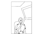
画像取得部1は、カメラ9が撮影した車両内の乗員の画像を取得する。カメラ9は、運転席、助手席、および後部座席のそれぞれに着座した乗員を含むように撮影する。図2は、助手席に着座している乗員の画像の一例を示す図である。なお、図2の例では、助手席に乗員が着座している場合を示しているが、これに限るものではない。カメラ9が撮影した画像には、運転席に着座している乗員、および後部座席に着座している乗員が含まれていてもよい。
The image acquisition unit 1 acquires an image of the occupant in the vehicle taken by the camera 9. The camera 9 photographs the occupants seated in the driver's seat, the passenger seat, and the rear seat, respectively. FIG. 2 is a diagram showing an example of an image of an occupant seated in the passenger seat. The example of FIG. 2 shows a case where the occupant is seated in the passenger seat, but the present invention is not limited to this. The image taken by the camera 9 may include an occupant seated in the driver's seat and an occupant seated in the rear seat.
顔特徴点推定部2は、画像取得部1が取得した画像に基づいて、乗員の顔の特徴点を推定する。具体的には、顔特徴点推定部2は、画像取得部1が取得した画像を予め準備した学習辞書(図示せず)と照合し、画像取得部1が取得した画像に含まれる乗員の顔、目、および鼻などの位置を示す顔の特徴点を推定する。例えば、顔特徴点推定部2は、乗員の瞳孔の位置および大きさ、両目の各瞳孔の中心の間隔である両目の間隔、眉の両端位置、目の両端位置、鼻頭の位置、口の両端位置などを顔の特徴点として推定するが、これらに限らず顔の他の特徴点を推定してもよい。学習辞書には、複数の人物の顔の特徴点が記録されている。なお、顔特徴点推定部2は、画像に複数の乗員が含まれている場合、各乗員の顔の特徴点を推定する。
The facial feature point estimation unit 2 estimates the facial feature points of the occupant based on the image acquired by the image acquisition unit 1. Specifically, the face feature point estimation unit 2 collates the image acquired by the image acquisition unit 1 with a learning dictionary (not shown) prepared in advance, and the face of the occupant included in the image acquired by the image acquisition unit 1. Estimate facial feature points that indicate positions such as, eyes, and nose. For example, the facial feature point estimation unit 2 includes the position and size of the occupant's pupil, the distance between the centers of the pupils of both eyes, the position of both ends of the eyebrows, the position of both ends of the eyes, the position of the tip of the nose, and both ends of the mouth. The position and the like are estimated as facial feature points, but the present invention is not limited to these, and other facial feature points may be estimated. In the learning dictionary, the feature points of the faces of a plurality of people are recorded. When the image includes a plurality of occupants, the face feature point estimation unit 2 estimates the facial feature points of each occupant.
図3は、乗員の顔の特徴点の一例を示す図である。図3に示す乗員は、助手席に着座している。図3において、乗員の顔を四角で囲んだ線は、乗員の顔の位置を示している。乗員の目の中心に破線で示した円は、乗員の瞳孔の位置および大きさを示している。乗員の顔に示した複数の点は、眉の両端位置、目の両端位置、鼻頭の位置、口の両端位置をそれぞれ示している。また、目幅は、乗員の両目の間隔であり、具体的には各瞳孔の中心の間隔である。なお、顔特徴点推定部2は、図3に示す顔の特徴点に限らず、顔の他の特徴点を推定してもよい。
FIG. 3 is a diagram showing an example of the feature points of the occupant's face. The occupant shown in FIG. 3 is seated in the passenger seat. In FIG. 3, the line surrounding the occupant's face with a square indicates the position of the occupant's face. The dashed circle in the center of the occupant's eyes indicates the position and size of the occupant's pupil. The plurality of dots shown on the occupant's face indicate the positions of both ends of the eyebrows, the positions of both ends of the eyes, the position of the tip of the nose, and the positions of both ends of the mouth. The eye width is the distance between the occupant's eyes, specifically the distance between the centers of each pupil. The facial feature point estimation unit 2 may estimate not only the facial feature points shown in FIG. 3 but also other facial feature points.
頭位置推定部3は、顔特徴点推定部2が推定した顔の特徴点に基づいて、カメラ9に対する乗員の頭の相対的な位置を推定する。具体的には、頭位置推定部3は、顔特徴点推定部2が推定した乗員の両目の間隔または瞳孔の大きさに基づいて、カメラ9に対する乗員の頭の物理的な相対位置を推定する。すなわち、頭位置推定部3は、カメラ9と乗員の頭との距離を推定する。
The head position estimation unit 3 estimates the relative position of the occupant's head with respect to the camera 9 based on the facial feature points estimated by the face feature point estimation unit 2. Specifically, the head position estimation unit 3 estimates the physical relative position of the occupant's head with respect to the camera 9 based on the distance between the occupant's eyes or the size of the pupil estimated by the face feature point estimation unit 2. .. That is, the head position estimation unit 3 estimates the distance between the camera 9 and the occupant's head.
本実施の形態では、体格差の影響が少ない乗員の両目の間隔または瞳孔の大きさに基づいて、カメラ9に対する乗員の頭の相対的な位置を推定している。従って、乗員の体格に関わらず、カメラ9に対する乗員の頭の相対的な位置を精度良く推定することができる。また、乗員が着座している座席位置が変化した場合であっても、当該変化に応じて、カメラ9に対する乗員の頭の相対的な位置を精度良く推定することができる。
In the present embodiment, the relative position of the occupant's head with respect to the camera 9 is estimated based on the distance between the occupant's eyes or the size of the pupil, which is less affected by the physical disparity. Therefore, regardless of the physique of the occupant, the relative position of the occupant's head with respect to the camera 9 can be estimated accurately. Further, even when the seat position in which the occupant is seated changes, the relative position of the occupant's head with respect to the camera 9 can be accurately estimated according to the change.
部位推定部4は、画像取得部1が取得した画像に基づいて、画像における乗員の複数の部位の大きさを推定する。具体的には、部位推定部4は、画像取得部1が取得した画像を予め準備した学習辞書(図示せず)と照合し、画像取得部1が取得した画像に含まれる乗員の首、肩、腕、手、および上半身などの各部位の画像における大きさおよび位置を推定する。学習辞書には、複数の人物の各部位の画像における大きさおよび位置が記録されている。なお、部位推定部4は、画像に複数の乗員が含まれている場合、各乗員の複数の部位の大きさを推定する。また、部位推定部4が推定した画像における乗員の各部位の大きさの単位はpix(ピクセル)である。
The part estimation unit 4 estimates the sizes of a plurality of parts of the occupant in the image based on the image acquired by the image acquisition unit 1. Specifically, the site estimation unit 4 collates the image acquired by the image acquisition unit 1 with a learning dictionary (not shown) prepared in advance, and the neck and shoulders of the occupant included in the image acquired by the image acquisition unit 1. Estimate the size and position of each part in the image, such as, arms, hands, and upper body. In the learning dictionary, the size and position of each part of a plurality of people in the image are recorded. When a plurality of occupants are included in the image, the part estimation unit 4 estimates the sizes of the plurality of parts of each occupant. Further, the unit of the size of each part of the occupant in the image estimated by the part estimation unit 4 is pix (pixel).
図4から図7は、画像取得部1が取得した画像における乗員の複数の部位の大きさおよび位置の一例を示す図である。図4から図6は、体格が異なる乗員の各部位の大きさおよび位置を示している。図4から図7において、各点を結ぶ直線は乗員の部位に対応し、各部位の大きさの単位はpix(ピクセル)である。例えば、図7に示す両矢印は、乗員の肩幅(nピクセル)を示している。
4 to 7 are diagrams showing an example of the size and position of a plurality of parts of the occupant in the image acquired by the image acquisition unit 1. 4 to 6 show the size and position of each part of the occupants having different physiques. In FIGS. 4 to 7, the straight line connecting the points corresponds to the occupant's part, and the unit of the size of each part is pix (pixel). For example, the double-headed arrow shown in FIG. 7 indicates the shoulder width (n pixels) of the occupant.
骨格推定部5は、頭位置推定部3が推定したカメラ9に対する乗員の頭の相対的な位置と、部位推定部4が推定した画像における乗員の各部位の大きさとに基づいて、乗員の骨格および乗員の手の伸びている方向を推定する。具体的には、まず、骨格推定部5は、部位推定部4が推定した画像における乗員の各部位の大きさを、乗員の各部位の実際の大きさに変換する。なお、骨格推定部5は、乗員が複数である場合、各乗員の各部位の実際の大きさを推定する。
The skeleton estimation unit 5 determines the skeleton of the occupant based on the relative position of the occupant's head with respect to the camera 9 estimated by the head position estimation unit 3 and the size of each part of the occupant in the image estimated by the part estimation unit 4. And estimate the direction in which the occupant's hand is extending. Specifically, first, the skeleton estimation unit 5 converts the size of each part of the occupant in the image estimated by the part estimation unit 4 into the actual size of each part of the occupant. When there are a plurality of occupants, the skeleton estimation unit 5 estimates the actual size of each part of each occupant.
ここで、骨格推定部5が、部位推定部4が推定した画像における乗員の肩幅を実際の肩幅に変換する方法について説明する。骨格推定部5は、下記の式(1)に従って、実際の肩幅dを算出する。
d=Mn/{2xtan(θ/2)}・・・(1) Here, a method in which theskeleton estimation unit 5 converts the occupant's shoulder width in the image estimated by the site estimation unit 4 into an actual shoulder width will be described. The skeleton estimation unit 5 calculates the actual shoulder width d according to the following equation (1).
d = Mn / {2xtan (θ / 2)} ... (1)
d=Mn/{2xtan(θ/2)}・・・(1) Here, a method in which the
d = Mn / {2xtan (θ / 2)} ... (1)
式(1)において、nは、画像における肩幅の大きさを示している。Mは、画像の横幅を示しており、カメラ9の画角θによって決まる。xは、カメラ9と乗員の頭との距離を示しており、頭位置推定部3が推定したカメラ9に対する乗員の頭の相対的な位置に対応する。このように、骨格推定部5は、部位推定部4が推定した画像における各部位の大きさを、頭位置推定部3が推定した乗員の頭の相対的な位置で補正することによって、乗員の各部位の実際の大きさを算出する。
In formula (1), n indicates the size of the shoulder width in the image. M indicates the width of the image, which is determined by the angle of view θ of the camera 9. x indicates the distance between the camera 9 and the occupant's head, and corresponds to the relative position of the occupant's head with respect to the camera 9 estimated by the head position estimation unit 3. In this way, the skeleton estimation unit 5 corrects the size of each part in the image estimated by the part estimation unit 4 with the relative position of the occupant's head estimated by the head position estimation unit 3, thereby causing the occupant to Calculate the actual size of each part.
上記の式(1)に示すように、骨格推定部5は、頭位置推定部3が推定したカメラ9に対する乗員の頭の相対的な位置を用いて、乗員の各部位の実際の大きさを算出している。従って、乗員が着座している座席位置が変化した場合であっても、骨格推定部5は乗員の各部位の実際の大きさを正確に算出することができる。なお、上記では、乗員の肩幅を算出する場合について説明したが、乗員の他の部位についても同様に算出することができる。例えば、骨格推定部5は、乗員の座高、顔の大きさ、および腕の長さを算出してもよい。
As shown in the above equation (1), the skeleton estimation unit 5 uses the relative position of the occupant's head with respect to the camera 9 estimated by the head position estimation unit 3 to determine the actual size of each part of the occupant. It is calculated. Therefore, even when the seat position in which the occupant is seated changes, the skeleton estimation unit 5 can accurately calculate the actual size of each portion of the occupant. In the above description, the case of calculating the shoulder width of the occupant has been described, but the calculation can be performed in the same manner for other parts of the occupant. For example, the skeleton estimation unit 5 may calculate the sitting height of the occupant, the size of the face, and the length of the arm.
画像における乗員の各部位の大きさを、乗員の各部位の実際の大きさに変換することができるのは、カメラ9に対する乗員の頭の相対的な位置に乗員の全ての部位が存在していると仮定しているからである。肩、背骨、および顔が、カメラ9に対する乗員の頭の相対的な位置とほぼ同じ位置に存在することは想定できるが、腕は肩を中心として大きく動かすことができるためこの限りではない。腕については、部位推定部4は、画像の経時的な変化で腕の大きさが最大となったとき、当該最大となった腕の大きさを乗員の腕の大きさと推定してもよい。この場合、骨格推定部5は、部位推定部4が推定した画像における腕の大きさを、実際の腕の大きさに変換する。
The size of each part of the occupant in the image can be converted to the actual size of each part of the occupant because all the parts of the occupant are present at the relative position of the occupant's head with respect to the camera 9. This is because it is assumed that there is. It can be assumed that the shoulders, spine, and face are located approximately at the same positions as the occupant's head relative to the camera 9, but this is not the case because the arms can be moved significantly around the shoulders. With respect to the arm, the site estimation unit 4 may estimate the maximum arm size as the occupant's arm size when the arm size becomes maximum due to a change over time in the image. In this case, the skeleton estimation unit 5 converts the arm size in the image estimated by the site estimation unit 4 into the actual arm size.
次に、骨格推定部5は、乗員の各部位の実際の大きさに基づいて、乗員の骨格を推定する。具体的には、骨格推定部5は、乗員の骨格を推定するための機械学習を行った学習済みの学習器(図示せず)に、乗員の各部位の実際の大きさを入力し、学習器の演算処理を実行することで、乗員の骨格の推定結果を学習器から取得する。なお、骨格推定部5は、乗員が複数である場合、各乗員の骨格を推定する。
Next, the skeleton estimation unit 5 estimates the skeleton of the occupant based on the actual size of each part of the occupant. Specifically, the skeleton estimation unit 5 inputs the actual size of each part of the occupant into a learned learner (not shown) that has been machine-learned to estimate the skeleton of the occupant, and learns. By executing the arithmetic processing of the instrument, the estimation result of the skeleton of the occupant is acquired from the learner. When there are a plurality of occupants, the skeleton estimation unit 5 estimates the skeleton of each occupant.
学習器は、複数の人物の各部位の実際の大きさと、各人物の骨格とを対応付けて記録された学習辞書(図示せず)を有している。例えば、骨格推定部5が、乗員の座高、肩幅、顔の大きさ、および腕の長さを学習器に入力した場合、学習器は、入力した各部位の実際の大きさを学習辞書と照合し、尤度が最も大きい骨格が、入力した各部位を有する乗員の骨格であると推定する。このように、乗員の各部位の実際の大きさと乗員の骨格とは相関関係を有している。骨格推定部5は、乗員の骨格の推定結果を学習器から取得する。
The learning device has a learning dictionary (not shown) recorded by associating the actual size of each part of a plurality of persons with the skeleton of each person. For example, when the skeleton estimation unit 5 inputs the occupant's sitting height, shoulder width, face size, and arm length into the learning device, the learning device collates the actual size of each input part with the learning dictionary. Then, it is presumed that the skeleton with the highest likelihood is the skeleton of the occupant having each input part. In this way, there is a correlation between the actual size of each part of the occupant and the skeleton of the occupant. The skeleton estimation unit 5 acquires the estimation result of the skeleton of the occupant from the learner.
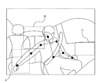
次に、骨格推定部5は、推定した乗員の骨格から乗員の手の伸びている方向を推定する。例えば、骨格推定部5は、予め設定された骨格検知エリアにおいて乗員の手が検知されることによって乗員の手の伸びている方向を検出する。図8は、画像取得部1が取得した画像における乗員の手の伸びている方向を検出するための一例を示す図である。
Next, the skeleton estimation unit 5 estimates the direction in which the occupant's hand extends from the estimated occupant's skeleton. For example, the skeleton estimation unit 5 detects the direction in which the occupant's hand is extended by detecting the occupant's hand in the preset skeleton detection area. FIG. 8 is a diagram showing an example for detecting the extending direction of the occupant's hand in the image acquired by the image acquisition unit 1.
図8に示す例では、乗員は、助手席に着座している。図8において、点線で囲まれた各エリアは、予め設定された各骨格検知エリアを示している。図8に示す例では、骨格検知エリアとして設定されたエリアは、検知対象の乗員に対する隣席エリア、検知対象の乗員に対する後席エリア、および検知対象の乗員が乗車または降車するためのドアのドアノブエリアである。なお、図8に示す例で設定された各骨格検知エリアは、乗員が助手席に着座している場合の例であり、検知対象の乗員の着座位置に応じて適宜設定される。また、各検知エリアの大きさは、任意に設定可能であり、検知対象の乗員に応じて適宜設定される。
In the example shown in FIG. 8, the occupant is seated in the passenger seat. In FIG. 8, each area surrounded by a dotted line indicates each preset skeleton detection area. In the example shown in FIG. 8, the areas set as the skeleton detection area are the adjacent seat area for the occupant to be detected, the rear seat area for the occupant to be detected, and the doorknob area of the door for the occupant to be detected to get on or off. Is. Each skeleton detection area set in the example shown in FIG. 8 is an example in the case where the occupant is seated in the passenger seat, and is appropriately set according to the seating position of the occupant to be detected. Further, the size of each detection area can be arbitrarily set, and is appropriately set according to the occupant to be detected.
図8に示す例において、骨格検知エリアAにて乗員の手が検知された場合、骨格推定部5は、乗員の手が隣席方向に伸びていると推定する。図8に示す例において、骨格検知エリアBにて乗員の手が検知された場合、骨格推定部5は、乗員の手が後席方向に伸びていると推定する。図8に示す例において、骨格検知エリアCにて乗員の手が検知された場合、骨格推定部5は、乗員の手がドアノブ方向に伸びていると推定する。予め設定された骨格検知エリア以外で乗員の手が検知された場合、および複数の骨格検知エリアにて乗員の手が検知された場合は、骨格推定部5は、乗員の手の方向を推定不可と判断する。なお、図8では、検知対象の乗員が助手席に着座している場合の例を示したが、検知対象の乗員は助手席に着座している乗員に限られるものではない。
In the example shown in FIG. 8, when the occupant's hand is detected in the skeleton detection area A, the skeleton estimation unit 5 estimates that the occupant's hand extends toward the adjacent seat. In the example shown in FIG. 8, when the occupant's hand is detected in the skeleton detection area B, the skeleton estimation unit 5 estimates that the occupant's hand extends toward the rear seat. In the example shown in FIG. 8, when the occupant's hand is detected in the skeleton detection area C, the skeleton estimation unit 5 estimates that the occupant's hand extends in the direction of the doorknob. If the occupant's hand is detected outside the preset skeleton detection area, or if the occupant's hand is detected in a plurality of skeleton detection areas, the skeleton estimation unit 5 cannot estimate the direction of the occupant's hand. Judge. Although FIG. 8 shows an example in which the occupant to be detected is seated in the passenger seat, the occupant to be detected is not limited to the occupant seated in the passenger seat.
顔向き検出部6は、顔特徴点推定部2が推定した乗員の顔の特徴点である顔、目、および鼻などの位置関係に基づいて、顔向きを検出する。例えば、顔向き検出部6は、乗員の顔画像から顔部位に対応する特徴点を抽出し、その特徴点により示される顔部位の位置関係に基づいて、乗員の顔向き角度を算出する。顔向き角度は、例えば、公知の技術であるPOSIT(Pose from Orthography and Scaling with Iterations)アルゴリズムを用いて検出することができる。
The face orientation detection unit 6 detects the face orientation based on the positional relationship of the face, eyes, nose, etc., which are the facial feature points of the occupant estimated by the face feature point estimation unit 2. For example, the face orientation detection unit 6 extracts feature points corresponding to the face portion from the face image of the occupant, and calculates the face orientation angle of the occupant based on the positional relationship of the face portion indicated by the feature points. The face orientation angle can be detected using, for example, a known technique, the POSIT (Pose from Orthography and Scaling with Iterations) algorithm.
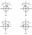
顔向き検出部6は、検出した顔向き角度から乗員の顔向きを検出する。例えば、顔向き検出部6は、乗員の顔向きとして、検知対象の乗員に対して隣席方向を向いているか、検知対象の乗員に対して後席方向を向いているか、または検知対象の乗員が乗車または降車するためのドアのドアノブ方向を向いているかを検出する。ここで、図9は、乗員の顔向きの一例を示す図であり、乗員の頭部を真上から見た状態を示している。図9では、乗員の顔向きを一点鎖線で示しており、乗員の顔向きが車両の進行方向Yと一致している場合に、顔向き角度は0°とする。
The face orientation detection unit 6 detects the occupant's face orientation from the detected face orientation angle. For example, the face orientation detection unit 6 faces the occupant in the direction of the adjacent seat with respect to the occupant to be detected, is oriented toward the rear seat with respect to the occupant to be detected, or the occupant to be detected is facing the rear seat. Detects whether the door is facing the door knob for getting on or off. Here, FIG. 9 is a diagram showing an example of the occupant's face orientation, showing a state in which the occupant's head is viewed from directly above. In FIG. 9, the face orientation of the occupant is indicated by a chain line, and when the occupant's face orientation coincides with the traveling direction Y of the vehicle, the face orientation angle is set to 0 °.
次に、顔向き検出部6による乗員の顔向き検出例について図9を用いて説明する。なお、図9に示す例では、乗員は、助手席に着座している。
図9(a)に示すように、乗員の顔向きが車両の進行方向Yから右方向に回転している場合は、顔向き角度が0°から所定角度α以下の場合に、顔向き検出部6は、乗員は隣席方向を向いていると判断する。
図9(b)に示すように、乗員の顔向きが車両の進行方向Yから左方向に回転している場合は、顔向き角度が0°から所定角度β以下の場合に、顔向き検出部6は、乗員はドアノブ方向を向いていると判断する。
図9(c)に示すように、乗員の顔向きが車両の進行方向Yから右方向に所定角度αを超えて回転している場合、顔向き検出部6は、乗員は後席方向を向いていると判断する。
図9(d)に示すように、乗員の顔向きが車両の進行方向Yから左方向に所定角度βを超えて回転している場合、顔向き検出部6は、乗員は後席方向を向いていると判断する。 Next, an example of detecting the face orientation of the occupant by the faceorientation detecting unit 6 will be described with reference to FIG. In the example shown in FIG. 9, the occupant is seated in the passenger seat.
As shown in FIG. 9A, when the occupant's face orientation is rotating to the right from the vehicle's traveling direction Y, the face orientation detection unit is when the face orientation angle is 0 ° to a predetermined angle α or less. 6 determines that the occupant is facing the direction of the next seat.
As shown in FIG. 9B, when the occupant's face orientation is rotating to the left from the vehicle's traveling direction Y, the face orientation detection unit is when the face orientation angle is 0 ° to a predetermined angle β or less. 6 determines that the occupant is facing the door knob direction.
As shown in FIG. 9C, when the occupant's face orientation is rotating to the right from the traveling direction Y of the vehicle by exceeding a predetermined angle α, the faceorientation detection unit 6 causes the occupant to face the rear seat direction. Judge that
As shown in FIG. 9D, when the occupant's face orientation is rotating to the left from the traveling direction Y of the vehicle by exceeding a predetermined angle β, the faceorientation detection unit 6 causes the occupant to face the rear seat direction. Judge that
図9(a)に示すように、乗員の顔向きが車両の進行方向Yから右方向に回転している場合は、顔向き角度が0°から所定角度α以下の場合に、顔向き検出部6は、乗員は隣席方向を向いていると判断する。
図9(b)に示すように、乗員の顔向きが車両の進行方向Yから左方向に回転している場合は、顔向き角度が0°から所定角度β以下の場合に、顔向き検出部6は、乗員はドアノブ方向を向いていると判断する。
図9(c)に示すように、乗員の顔向きが車両の進行方向Yから右方向に所定角度αを超えて回転している場合、顔向き検出部6は、乗員は後席方向を向いていると判断する。
図9(d)に示すように、乗員の顔向きが車両の進行方向Yから左方向に所定角度βを超えて回転している場合、顔向き検出部6は、乗員は後席方向を向いていると判断する。 Next, an example of detecting the face orientation of the occupant by the face
As shown in FIG. 9A, when the occupant's face orientation is rotating to the right from the vehicle's traveling direction Y, the face orientation detection unit is when the face orientation angle is 0 ° to a predetermined angle α or less. 6 determines that the occupant is facing the direction of the next seat.
As shown in FIG. 9B, when the occupant's face orientation is rotating to the left from the vehicle's traveling direction Y, the face orientation detection unit is when the face orientation angle is 0 ° to a predetermined angle β or less. 6 determines that the occupant is facing the door knob direction.
As shown in FIG. 9C, when the occupant's face orientation is rotating to the right from the traveling direction Y of the vehicle by exceeding a predetermined angle α, the face
As shown in FIG. 9D, when the occupant's face orientation is rotating to the left from the traveling direction Y of the vehicle by exceeding a predetermined angle β, the face
ここで、所定角度αおよび所定角度βとしては、後席方向を向く過程で取り得る角度を設定する。所定角度αおよび所定角度βは、例えば50度に設定される。なお、所定角度αおよび所定角度βは、任意に設定可能であり、所定角度αと所定角度βとは異なる値を設定することができる。図9では、検知対象の乗員が助手席に着座している場合の例を示したが、検知対象の乗員は助手席に着座している乗員に限られるものではない。また、顔向き検出部6によって判断される乗員の顔向きは、検知対象の乗員の着座位置に応じて決定される。
Here, as the predetermined angle α and the predetermined angle β, the angles that can be taken in the process of facing the rear seat direction are set. The predetermined angle α and the predetermined angle β are set to, for example, 50 degrees. The predetermined angle α and the predetermined angle β can be arbitrarily set, and different values can be set between the predetermined angle α and the predetermined angle β. Although FIG. 9 shows an example in which the occupant to be detected is seated in the passenger seat, the occupant to be detected is not limited to the occupant seated in the passenger seat. Further, the face orientation of the occupant determined by the face orientation detection unit 6 is determined according to the seating position of the occupant to be detected.
また、顔向き検出部6は、顔特徴点推定部2が推定した特徴点から乗員の視野または視線を検出する構成としてもよい。つまり、顔向き検出部6は、顔特徴点推定部2が推定した乗員の顔の特徴点に基づき、乗員の顔向き角度と、乗員の視野または視線とを算出し、算出した乗員の顔向き角度と、乗員の視野または視線とに基づき、乗員の顔向きを検出する構成としてもよい。例えば、顔向き検出部6は、顔特徴点推定部2が推定した乗員の瞳孔の位置および大きさ、両目の各瞳孔の中心の間隔である両目の間隔、眉の両端位置、目の両端位置から視野または視線を検出する。視野または視線は、公知の視線検出処理を用いて検出することができる。
Further, the face orientation detection unit 6 may be configured to detect the visual field or the line of sight of the occupant from the feature points estimated by the face feature point estimation unit 2. That is, the face orientation detection unit 6 calculates the occupant's face orientation angle and the occupant's field of view or line of sight based on the occupant's face feature points estimated by the face feature point estimation unit 2, and calculates the occupant's face orientation. The configuration may be such that the face orientation of the occupant is detected based on the angle and the occupant's field of view or line of sight. For example, the face orientation detection unit 6 includes the position and size of the occupant's pupils estimated by the face feature point estimation unit 2, the distance between the centers of the pupils of both eyes, the distance between both eyes, the position at both ends of the eyebrows, and the position at both ends of the eyes. Detect the visual field or line of sight from. The visual field or line of sight can be detected using a known line of sight detection process.
顔向き検出部6は、視野または視線として、視線方向角度を検出する。視線方向角度とは、乗員の顔向き角度に対する乗員の視線の方向を示す角度である。顔向き検出部6が乗員の視線方向角度を検出する構成である場合、顔向き検出部6は、乗員の視線方向角度を考慮した顔向き角度を算出し、顔向きを検出する。例えば、顔向き検出部6は、車両の進行方向Yに対する乗員の顔向き角度の回転方向と、乗員の顔向き角度に対する乗員の視線方向角度の回転方向とが、同一の場合は、乗員の顔向き角度に乗員の視線方向角度を加算した値を乗員の視線方向角度を考慮した顔向き角度として算出する。一方、顔向き検出部6は、車両の進行方向Yに対する乗員の顔向き角度の回転方向と、乗員の顔向き角度に対する乗員の視線方向角度の回転方向とが、異なる場合は、乗員の顔向き角度から乗員の視線方向角度を減算した値を乗員の視線方向角度を考慮した顔向き角度として算出する。つまり、顔向き検出部6は、乗員の顔向き角度に加えて乗員の視線方向角度をさらに利用して算出した、乗員の視線方向角度を考慮した顔向き角度に基づいて、顔向きを検出する。
The face orientation detection unit 6 detects the line-of-sight direction angle as a field of view or a line of sight. The line-of-sight angle is an angle indicating the direction of the occupant's line of sight with respect to the occupant's face-facing angle. When the face orientation detection unit 6 is configured to detect the line-of-sight direction angle of the occupant, the face orientation detection unit 6 calculates the face-direction angle in consideration of the line-of-sight direction angle of the occupant and detects the face orientation. For example, when the rotation direction of the occupant's face orientation angle with respect to the vehicle's traveling direction Y and the rotation direction of the occupant's line-of-sight direction angle with respect to the occupant's face orientation angle, the face orientation detection unit 6 is the occupant's face. The value obtained by adding the occupant's line-of-sight direction angle to the direction angle is calculated as the face direction angle in consideration of the occupant's line-of-sight direction angle. On the other hand, when the rotation direction of the occupant's face orientation angle with respect to the vehicle's traveling direction Y and the rotation direction of the occupant's line-of-sight direction angle with respect to the occupant's face orientation angle are different, the face orientation detection unit 6 faces the occupant's face. The value obtained by subtracting the occupant's line-of-sight direction angle from the angle is calculated as the face orientation angle in consideration of the occupant's line-of-sight direction angle. That is, the face orientation detection unit 6 detects the face orientation based on the face orientation angle in consideration of the occupant's line-of-sight direction angle calculated by further utilizing the occupant's line-of-sight direction angle in addition to the occupant's face-direction angle. ..
ここで、図10は、乗員の視線方向角度を考慮した乗員の顔向きの一例を示す図であり、乗員の頭部を真上から見た状態を示している。図10では、乗員の顔向きを一点鎖線で示しており、乗員の視線方向角度を破線で示している。なお、乗員の顔向きが車両の進行方向Yと一致している場合は、顔向き角度は0°とする。また、乗員の顔向きと乗員の視線方向角度とが一致している場合は、乗員の視線方向角度は0°とする。
Here, FIG. 10 is a diagram showing an example of the occupant's face orientation in consideration of the occupant's line-of-sight direction angle, and shows a state in which the occupant's head is viewed from directly above. In FIG. 10, the face orientation of the occupant is indicated by a chain line, and the line-of-sight direction angle of the occupant is indicated by a broken line. If the occupant's face orientation coincides with the vehicle's traveling direction Y, the face orientation angle is set to 0 °. If the occupant's face orientation and the occupant's line-of-sight direction angle match, the occupant's line-of-sight direction angle is set to 0 °.
次に、顔向き検出部6による乗員の視線方向角度を考慮した乗員の顔向き検出例について図10を用いて説明する。なお、図10に示す例では、乗員は、助手席に着座している。図10に示す例では、乗員の顔向き角度は、車両の進行方向Yから右方向にA°である。また、乗員の視線方向角度は、乗員の顔向き角度から左にa°である。つまり、図10に示す例では、顔向き検出部6は、乗員の視線方向角度を考慮した顔向き角度として、A°―a°を算出し、乗員の視線方向角度を考慮した顔向き角度A°―a°が0°から所定角度α以下の場合は、乗員は隣席方向を向いていると判断する。
Next, an example of occupant's face orientation detection in consideration of the occupant's line-of-sight direction angle by the face orientation detection unit 6 will be described with reference to FIG. In the example shown in FIG. 10, the occupant is seated in the passenger seat. In the example shown in FIG. 10, the face-facing angle of the occupant is A ° to the right from the traveling direction Y of the vehicle. The line-of-sight direction angle of the occupant is a ° to the left of the occupant's face-facing angle. That is, in the example shown in FIG. 10, the face orientation detection unit 6 calculates A ° −a ° as the face orientation angle in consideration of the line-of-sight direction angle of the occupant, and the face orientation angle A in consideration of the line-of-sight direction angle of the occupant. When ° -a ° is from 0 ° to a predetermined angle α or less, it is determined that the occupant is facing the direction of the next seat.
つまり、顔向き検出部6は、乗員の視線方向角度を考慮した顔向き角度が0°から所定角度α以下の場合は、乗員は隣席方向を向いていると判断し、乗員の視線方向角度を考慮した顔向き角度が所定角度αを超えている場合は、乗員は後席方向を向いていると判断する。また、顔向き検出部6は、乗員の視線方向角度を考慮した顔向き角度が0°から所定角度β以下の場合は、乗員はドアノブ方向を向いていると判断し、乗員の視線方向角度を考慮した顔向き角度が所定角度βを超えている場合は、乗員は後席方向を向いていると判断する。
That is, when the face orientation angle considering the occupant's line-of-sight direction angle is 0 ° to a predetermined angle α or less, the face orientation detection unit 6 determines that the occupant is facing the adjacent seat direction and determines the occupant's line-of-sight direction angle. If the considered face-facing angle exceeds the predetermined angle α, it is determined that the occupant is facing the rear seat direction. Further, the face orientation detection unit 6 determines that the occupant is facing the door knob direction when the face orientation angle considering the occupant's line-of-sight direction angle is 0 ° to a predetermined angle β or less, and determines the occupant's line-of-sight direction angle. If the considered face-facing angle exceeds the predetermined angle β, it is determined that the occupant is facing the rear seat direction.
注意方向判定部7は、骨格推定部5が推定した乗員の手の伸びている方向と、顔向き検出部6が推定した乗員の顔向きとに基づいて、乗員が注意を向けている方向を判定する。さらに、注意方向判定部7は、判定した判定結果を判定結果出力部8に出力する。例えば、注意方向判定部7は、骨格推定部5が推定した乗員の手の伸びている方向と、顔向き検出部6が推定した乗員の顔向きとが同一の方向である場合に、乗員が注意を向けている方向は、骨格推定部5および顔向き検出部6が推定した方向であると判定する。一方、注意方向判定部7は、骨格推定部5が推定した乗員の手の伸びている方向と、顔向き検出部6が推定した乗員の顔向きとが同一ではない場合、骨格推定部5が推定した乗員の手の伸びている方向が推定不可である場合、および顔向き検出部6が推定した乗員の顔向きが推定不可である場合は、注意方向判定不可と判断する。
The attention direction determination unit 7 determines the direction in which the occupant is paying attention based on the direction in which the occupant's hand is extended estimated by the skeleton estimation unit 5 and the occupant's face orientation estimated by the face orientation detection unit 6. judge. Further, the attention direction determination unit 7 outputs the determined determination result to the determination result output unit 8. For example, in the attention direction determination unit 7, when the occupant's hand extension direction estimated by the skeleton estimation unit 5 and the occupant's face orientation estimated by the face orientation detection unit 6 are the same direction, the occupant It is determined that the direction of attention is the direction estimated by the skeleton estimation unit 5 and the face orientation detection unit 6. On the other hand, in the attention direction determination unit 7, if the direction in which the occupant's hand is extended estimated by the skeleton estimation unit 5 and the occupant's face orientation estimated by the face orientation detection unit 6 are not the same, the skeleton estimation unit 5 may perform the skeleton estimation unit 5. If the estimated occupant's hand extension direction cannot be estimated, or if the occupant's face orientation estimated by the face orientation detection unit 6 cannot be estimated, it is determined that the attention direction cannot be determined.
判定結果出力部8は、注意方向判定部7が判定した判定結果を制御部10に出力する。ここで、注意方向判定部7が判定した判定結果には、注意方向判定部7が注意方向判定不可と判断した判断結果も含まれる。
The determination result output unit 8 outputs the determination result determined by the attention direction determination unit 7 to the control unit 10. Here, the determination result determined by the attention direction determination unit 7 also includes the determination result that the attention direction determination unit 7 determines that the attention direction determination is impossible.
制御部10は、判定結果出力部8から出力された判定結果を受信し、判定結果に対応した車載機器等の制御を行う。例えば、制御部10は、乗員が注意を向けている方向は隣席方向であるという判定結果を受信した場合は、検知対象の乗員に対する隣席を照らす照明を点灯させるための制御を行う。また、制御部10は、乗員が注意を向けている方向は後席方向であるという判定結果を受信した場合は、検知対象の乗員に対する後席を照らす照明を点灯させるための制御を行う。また、制御部10は、乗員が注意を向けている方向はドアノブ方向であるという判定結果を受信した場合は、検知対象の乗員の足元を照らす照明を点灯させる制御を行う。なお、制御部10は、受信した判定結果が注意方向判定不可の場合は車載機器等の制御を行わない。
The control unit 10 receives the determination result output from the determination result output unit 8 and controls the in-vehicle device or the like corresponding to the determination result. For example, when the control unit 10 receives a determination result that the direction in which the occupant is paying attention is the direction of the next seat, the control unit 10 controls the occupant to be detected to turn on the lighting for illuminating the next seat. Further, when the control unit 10 receives the determination result that the direction in which the occupant is paying attention is the rear seat direction, the control unit 10 controls the occupant to be detected to turn on the illumination for illuminating the rear seat. Further, when the control unit 10 receives the determination result that the direction in which the occupant is paying attention is the doorknob direction, the control unit 10 controls to turn on the lighting that illuminates the feet of the occupant to be detected. The control unit 10 does not control the in-vehicle device or the like when the received determination result cannot determine the caution direction.
図11は、図1に示す注意方向判定装置100の動作の一例を示すフローチャートである。
FIG. 11 is a flowchart showing an example of the operation of the attention direction determination device 100 shown in FIG.
ステップS101において、画像取得部1は、カメラ9が撮影した車両内の乗員の画像を取得する。ステップS102において、顔特徴点推定部2は、画像取得部1が取得した画像に基づいて、乗員の顔の特徴点を推定する。
In step S101, the image acquisition unit 1 acquires an image of the occupant in the vehicle taken by the camera 9. In step S102, the facial feature point estimation unit 2 estimates the facial feature points of the occupant based on the image acquired by the image acquisition unit 1.
ステップS103において、頭位置推定部3は、顔特徴点推定部2が推定した顔の特徴点に基づいて、カメラ9に対する乗員の頭の相対的な位置を推定する。ステップS104において、部位推定部4は、画像取得部1が取得した画像に基づいて、画像における乗員の複数の部位の大きさを推定する。
In step S103, the head position estimation unit 3 estimates the relative position of the occupant's head with respect to the camera 9 based on the facial feature points estimated by the face feature point estimation unit 2. In step S104, the part estimation unit 4 estimates the sizes of a plurality of parts of the occupant in the image based on the image acquired by the image acquisition unit 1.
ステップS105において、骨格推定部5は、頭位置推定部3が推定した乗員の頭の相対的な位置と、部位推定部4が推定した各部位の大きさとに基づいて、乗員の骨格を推定する。ステップS106において、骨格推定部5は、推定した骨格が骨格検知エリアにおいて検知されるかを判定し、乗員の手の伸びている方向を推定する。
In step S105, the skeleton estimation unit 5 estimates the skeleton of the occupant based on the relative position of the occupant's head estimated by the head position estimation unit 3 and the size of each part estimated by the site estimation unit 4. .. In step S106, the skeleton estimation unit 5 determines whether the estimated skeleton is detected in the skeleton detection area, and estimates the direction in which the occupant's hand is extended.
ステップS107において、顔向き検出部6は、顔特徴点推定部2が推定した乗員の顔の特徴点である顔、目、および鼻などの位置関係に基づいて、乗員の顔向きを検出する。
In step S107, the face orientation detection unit 6 detects the occupant's face orientation based on the positional relationship of the occupant's face feature points such as the face, eyes, and nose estimated by the face feature point estimation unit 2.
ステップS108において、注意方向判定部7は、骨格推定部5が推定した乗員の手の伸びている方向と、顔向き検出部6が推定した乗員の顔向きとに基づいて、乗員が注意を向けている方向を判定する。
In step S108, the attention direction determination unit 7 directs the occupant's attention based on the direction in which the occupant's hand is extended estimated by the skeleton estimation unit 5 and the occupant's face orientation estimated by the face orientation detection unit 6. Determine the direction in which you are.
ステップS109において、判定結果出力部8は、注意方向判定部7が判定した判定結果を出力する。図1の例では、判定結果出力部8は、注意方向判定部7が判定した乗員が注意を向けている方向を制御部10に出力する。
In step S109, the determination result output unit 8 outputs the determination result determined by the attention direction determination unit 7. In the example of FIG. 1, the determination result output unit 8 outputs to the control unit 10 the direction in which the occupant determined by the attention direction determination unit 7 is paying attention.
本実施の形態1に係る注意方向判定装置は、カメラが撮影した車両内の乗員の画像を取得する画像取得部と、画像取得部が取得した画像に基づいて、乗員の顔の特徴点を推定する顔特徴点推定部と、画像取得部が取得した画像に基づいて、乗員の手の伸びている方向を推定する骨格推定部と、顔特徴点推定部が推定した顔の特徴点に基づいて、乗員の顔向きを検出する顔向き検出部と、骨格推定部が推定した乗員の手の伸びている方向と、顔向き検出部が検出した乗員の顔向きとに基づいて、乗員が注意を向けている方向を判定する注意方向判定部と、を備える。
The attention direction determining device according to the first embodiment estimates the feature points of the occupant's face based on the image acquisition unit that acquires the image of the occupant in the vehicle taken by the camera and the image acquired by the image acquisition unit. Based on the facial feature point estimation unit, the skeleton estimation unit that estimates the direction in which the occupant's hand is extending based on the image acquired by the image acquisition unit, and the facial feature points estimated by the facial feature point estimation unit. , The occupant pays attention based on the face orientation detection unit that detects the occupant's face orientation, the occupant's hand extension direction estimated by the skeleton estimation unit, and the occupant's face orientation detected by the face orientation detection unit. It is provided with a caution direction determining unit for determining the direction in which the vehicle is directed.
また、本実施の形態1に係る注意方向判定装置の注意方向判定部は、骨格推定部が推定した乗員の手の伸びている方向と、顔向き検出部が検出した乗員の顔向きとが同一の方向の場合に、乗員が注意を向けている方向を判定する。
Further, in the caution direction determination unit of the caution direction determination device according to the first embodiment, the direction in which the occupant's hand is extended estimated by the skeleton estimation unit and the occupant's face orientation detected by the face orientation detection unit are the same. In the case of the direction of, the direction in which the occupant is paying attention is determined.
また、本実施の形態1に係る注意方向判定装置の注意方向判定部は、骨格推定部が推定した乗員の手の伸びている方向が隣席方向であり、顔向き検出部が検出した乗員の顔向きが隣席方向である場合に、乗員が注意を向けている方向は隣席方向であると判定する。
Further, in the caution direction determination unit of the caution direction determination device according to the first embodiment, the direction in which the occupant's hand is extended is the direction of the adjacent seat estimated by the skeleton estimation unit, and the occupant's face detected by the face orientation detection unit. When the direction is the direction of the next seat, it is determined that the direction in which the occupant is paying attention is the direction of the next seat.
また、本実施の形態1に係る注意方向判定装置の注意方向判定部は、骨格推定部が推定した乗員の手の伸びている方向が後席方向であり、顔向き検出部が検出した乗員の顔向きが後席方向である場合に、乗員が注意を向けている方向は後席方向であると判定する。
Further, in the caution direction determination unit of the caution direction determination device according to the first embodiment, the direction in which the occupant's hand is extended as estimated by the skeleton estimation unit is the rear seat direction, and the occupant's face orientation detection unit detects it. When the face direction is the rear seat direction, it is determined that the direction in which the occupant is paying attention is the rear seat direction.
また、本実施の形態1に係る注意方向判定装置の注意方向判定部は、骨格推定部が推定した乗員の手の伸びている方向がドアノブ方向であり、顔向き検出部が検出した乗員の顔向きがドアノブ方向である場合に、乗員が注意を向けている方向はドアノブ方向であると判定する。
Further, in the caution direction determination unit of the caution direction determination device according to the first embodiment, the direction in which the occupant's hand is extended is the door knob direction estimated by the skeleton estimation unit, and the occupant's face detected by the face orientation detection unit. When the direction is the door knob direction, it is determined that the direction in which the occupant is paying attention is the door knob direction.
また、本実施の形態1に係る注意方向判定装置は、顔特徴点推定部が推定した顔の特徴点に基づいて、カメラに対する乗員の頭の相対的な位置を推定する頭位置推定部と、画像取得部が取得した画像に基づいて、画像における乗員の複数の部位の大きさを推定する部位推定部と、を有し、骨格推定部は、頭位置推定部が推定した乗員の頭の相対的な位置と、部位推定部が推定した各部位の大きさとに基づいて、乗員の骨格を推定し、推定した乗員の骨格推定結果から乗員の手の伸びている方向を推定する。
Further, the attention direction determination device according to the first embodiment includes a head position estimation unit that estimates the relative position of the occupant's head with respect to the camera based on the facial feature points estimated by the face feature point estimation unit. Based on the image acquired by the image acquisition unit, it has a part estimation unit that estimates the size of a plurality of parts of the occupant in the image, and the skeleton estimation unit is the relative of the occupant's head estimated by the head position estimation unit. The occupant's skeleton is estimated based on the target position and the size of each part estimated by the part estimation unit, and the direction in which the occupant's hand is extended is estimated from the estimated occupant's skeleton estimation result.
また、本実施の形態1に係る注意方向判定装置は、注意方向判定部が判定した乗員が注意を向けている方向を出力する判定結果出力部をさらに備えることを特徴とする。
Further, the attention direction determination device according to the first embodiment is further provided with a determination result output unit that outputs a direction in which the occupant determined by the attention direction determination unit is paying attention.
以上の構成によって実施の形態1に係る注意方向判定装置100は、乗員が注意を向けている方向を判定することができる。また、顔向き検出部6が、顔特徴点推定部2が推定した乗員の顔の特徴点である顔、目、および鼻などの位置関係に基づいて、顔向きを検出するため、注意方向判定装置100は、乗員がサングラスをしている場合であっても乗員が注意を向けている方向を判定することができる。
With the above configuration, the attention direction determination device 100 according to the first embodiment can determine the direction in which the occupant is paying attention. Further, since the face orientation detection unit 6 detects the face orientation based on the positional relationship of the occupant's face feature points such as the face, eyes, and nose estimated by the face feature point estimation unit 2, the attention direction determination is made. The device 100 can determine the direction in which the occupant is paying attention even when the occupant is wearing sunglasses.
実施の形態1に係る注意方向判定方法は、カメラが撮影した車両内の乗員の画像を取得するステップと、画像に基づいて、乗員の顔の特徴点を推定するステップと、画像に基づいて、乗員の手の伸びている方向を推定するステップと、顔の特徴点に基づいて、乗員の顔向きを検出するステップと、乗員の手の伸びている方向と、乗員の顔向きとに基づいて、乗員が注意を向けている方向を判定するステップと、を有する。
The attention direction determination method according to the first embodiment includes a step of acquiring an image of the occupant in the vehicle taken by the camera, a step of estimating a feature point of the occupant's face based on the image, and a step based on the image. Based on the step of estimating the extending direction of the occupant's hand, the step of detecting the occupant's face orientation based on the facial feature points, the extending direction of the occupant's hand, and the occupant's face orientation. It has a step of determining the direction in which the occupant is paying attention.
以上の構成によって実施の形態1に係る注意方向判定方法は、乗員が注意を向けている方向を判定することができる。
With the above configuration, the attention direction determination method according to the first embodiment can determine the direction in which the occupant is paying attention.
実施の形態2.
本開示の実施の形態2に係る注意方向判定装置200の構成について説明する。なお、実施の形態1と同一または対応する構成については、その説明を省略し、構成の異なる部分のみを説明する。Embodiment 2.
The configuration of the cautiondirection determination device 200 according to the second embodiment of the present disclosure will be described. The same or corresponding configurations as those in the first embodiment will be omitted, and only the parts having different configurations will be described.
本開示の実施の形態2に係る注意方向判定装置200の構成について説明する。なお、実施の形態1と同一または対応する構成については、その説明を省略し、構成の異なる部分のみを説明する。
The configuration of the caution
図12は、実施の形態2に係る注意方向判定装置200の構成の一例を示すブロック図である。図12に示すように、注意方向判定装置200は、着座情報取得部21と、車両情報取得部22とを備えている。
FIG. 12 is a block diagram showing an example of the configuration of the caution direction determination device 200 according to the second embodiment. As shown in FIG. 12, the attention direction determination device 200 includes a seating information acquisition unit 21 and a vehicle information acquisition unit 22.
着座情報取得部21は、カメラ9が撮影した車両内の乗員の画像から車両内の乗員の着座情報を取得する。ここで、着座情報とは乗員が車両内のどの座席に着座しているかを示す情報である。なお、着座情報取得部21による車両内の乗員の着座情報を取得は、カメラ9が撮影した車両内の乗員の画像から取得する構成に限られるものではない。例えば、車両に着座センサが設けられている場合、着座情報取得部21は、着座センサから車両内の乗員の着座情報を取得する構成としてもよい。
The seating information acquisition unit 21 acquires the seating information of the occupant in the vehicle from the image of the occupant in the vehicle taken by the camera 9. Here, the seating information is information indicating which seat in the vehicle the occupant is seated in. The acquisition of the seating information of the occupant in the vehicle by the seating information acquisition unit 21 is not limited to the configuration acquired from the image of the occupant in the vehicle taken by the camera 9. For example, when the vehicle is provided with a seating sensor, the seating information acquisition unit 21 may be configured to acquire the seating information of the occupant in the vehicle from the seating sensor.
車両情報取得部22は、車両の車両情報を取得する。ここで、車両情報とは、例えば、車両の停止に関する情報である。車両情報取得部22は、例えば、車両情報を車両に設けられた車速センサ等の車両センサ(図示せず)から取得する。
The vehicle information acquisition unit 22 acquires vehicle information of the vehicle. Here, the vehicle information is, for example, information regarding the stop of the vehicle. The vehicle information acquisition unit 22 acquires vehicle information from a vehicle sensor (not shown) such as a vehicle speed sensor provided in the vehicle, for example.
本開示の実施の形態2に係る注意方向判定部7は、骨格推定部5が推定した乗員の手の伸びている方向と、顔向き検出部6が検出した乗員の顔向きと、着座情報取得部21が取得した着座情報または車両情報取得部22が取得した車両情報の少なくとも一つの情報と、に基づいて乗員が注意を向けている方向を判定する。
The attention direction determination unit 7 according to the second embodiment of the present disclosure acquires the seating information, the direction in which the occupant's hand is extended estimated by the skeleton estimation unit 5, the occupant's face orientation detected by the face orientation detection unit 6, and the seating information. The direction in which the occupant is paying attention is determined based on at least one information of the seating information acquired by the unit 21 or the vehicle information acquired by the vehicle information acquisition unit 22.
次に、注意方向判定部7が、骨格推定部5が推定した乗員の手の伸びている方向と、顔向き検出部6が検出した乗員の顔向きと、着座情報取得部21が取得した着座情報と、に基づいて乗員が注意を向けている方向を判定する場合の判定例について説明する。
Next, the attention direction determination unit 7 determines the direction in which the occupant's hand is extended estimated by the skeleton estimation unit 5, the occupant's face orientation detected by the face orientation detection unit 6, and the seating acquired by the seating information acquisition unit 21. An example of determination in the case of determining the direction in which the occupant is paying attention based on the information will be described.
注意方向判定部7は、骨格推定部5が推定した乗員の手の伸びている方向が隣席方向であり、顔向き検出部6が検出した乗員の顔向きが隣席方向である場合に、さらに着座情報取得部21が取得した着座情報から隣席着座情報を取得し、乗員が注意を向けている方向を判定する。ここで、隣席着座情報とは、検知対象の乗員に対する隣席に乗員が着座しているかを示す情報である。つまり、注意方向判定部7は、骨格推定部5が推定した乗員の手の伸びている方向が隣席方向であり、顔向き検出部6が検出した乗員の顔向きが隣席方向であり、かつ着座情報取得部21が取得した着座情報が、検知対象の乗員に対する隣席に乗員が着座していないことを示す場合に、乗員が注意を向けている方向は隣席方向であると判定する構成としてもよい。一方、注意方向判定部7は、着座情報取得部21が取得した着座情報が、検知対象の乗員に対する隣席に乗員が着座していることを示す場合は、注意方向判定不可と判断する。
The attention direction determination unit 7 is further seated when the direction in which the occupant's hand is extended estimated by the skeleton estimation unit 5 is the direction of the next seat and the face direction of the occupant detected by the face orientation detection unit 6 is the direction of the next seat. The seating information for the next seat is acquired from the seating information acquired by the information acquisition unit 21, and the direction in which the occupant is paying attention is determined. Here, the next-seat seating information is information indicating whether or not the occupant is seated in the next-seat with respect to the occupant to be detected. That is, in the attention direction determination unit 7, the direction in which the occupant's hand is extended estimated by the skeleton estimation unit 5 is the direction of the next seat, and the direction of the occupant's face detected by the face orientation detection unit 6 is the direction of the next seat, and the seat is seated. When the seating information acquired by the information acquisition unit 21 indicates that the occupant is not seated in the seat next to the occupant to be detected, the direction in which the occupant is paying attention may be determined to be the direction of the next seat. .. On the other hand, when the seating information acquired by the seating information acquisition unit 21 indicates that the occupant is seated in the seat next to the occupant to be detected, the attention direction determination unit 7 determines that the attention direction determination is not possible.
注意方向判定部7は、骨格推定部5が推定した乗員の手の伸びている方向が後席方向であり、顔向き検出部6が検出した乗員の顔向きが後席方向である場合に、さらに着座情報取得部21が取得した着座情報から後席着座情報を取得し、乗員が注意を向けている方向を判定する。ここで、後席着座情報とは、検知対象の乗員に対する後席に乗員が着座しているかを示す情報である。つまり、注意方向判定部7は、骨格推定部5が推定した乗員の手の伸びている方向が後席方向であり、顔向き検出部6が検出した乗員の顔向きが後席方向であり、かつ着座情報取得部21が取得した着座情報が、検知対象の乗員に対する後席に乗員が着座していないことを示す場合に、乗員が注意を向けている方向は後席方向であると判定する構成としてもよい。一方、注意方向判定部7は、着座情報取得部21が取得した着座情報が、検知対象の乗員に対する後席に乗員が着座していることを示す場合は、注意方向判定不可と判断する。
When the attention direction determination unit 7 indicates that the occupant's hand extension direction estimated by the skeleton estimation unit 5 is the rear seat direction and the occupant's face direction detected by the face orientation detection unit 6 is the rear seat direction. Further, the rear seat seating information is acquired from the seating information acquired by the seating information acquisition unit 21, and the direction in which the occupant is paying attention is determined. Here, the rear seat seating information is information indicating whether or not the occupant is seated in the rear seat with respect to the occupant to be detected. That is, in the attention direction determination unit 7, the direction in which the occupant's hand is extended estimated by the skeleton estimation unit 5 is the rear seat direction, and the occupant's face direction detected by the face orientation detection unit 6 is the rear seat direction. Further, when the seating information acquired by the seating information acquisition unit 21 indicates that the occupant is not seated in the rear seat with respect to the occupant to be detected, it is determined that the direction in which the occupant is paying attention is the rear seat direction. It may be configured. On the other hand, when the seating information acquired by the seating information acquisition unit 21 indicates that the occupant is seated in the rear seat with respect to the occupant to be detected, the attention direction determination unit 7 determines that the attention direction determination is not possible.
次に、注意方向判定部7が、骨格推定部5が推定した乗員の手の伸びている方向と、顔向き検出部6が検出した乗員の顔向きと、車両情報取得部22が取得した車両情報と、に基づいて乗員が注意を向けている方向を判定する場合の判定例について説明する。
Next, the attention direction determination unit 7 determines the direction in which the occupant's hand is extended estimated by the skeleton estimation unit 5, the occupant's face orientation detected by the face orientation detection unit 6, and the vehicle acquired by the vehicle information acquisition unit 22. An example of determination in the case of determining the direction in which the occupant is paying attention based on the information will be described.
注意方向判定部7は、骨格推定部5が推定した乗員の手の伸びている方向がドアノブ方向であり、顔向き検出部6が検出した乗員の顔向きがドアノブ方向である場合に、さらに車両情報取得部22が取得した車両情報を用いて、乗員が注意を向けている方向を判定する。ここで、車両情報とは、車両の停止に関する情報である。つまり、注意方向判定部7は、骨格推定部5が推定した乗員の手の伸びている方向がドアノブ方向であり、顔向き検出部6が検出した乗員の顔向きがドアノブ方向であり、かつ車両情報取得部22が取得した車両情報が、車両が停止していることを示す場合に、乗員が注意を向けている方向はドアノブ方向であると判定する構成としてもよい。一方、注意方向判定部7は、車両情報取得部22が取得した車両情報が、車両が停止していないことを示す場合は、注意方向判定不可と判断する。
When the occupant's hand extension direction estimated by the skeleton estimation unit 5 is the door knob direction and the occupant's face direction detected by the face orientation detection unit 6 is the door knob direction, the attention direction determination unit 7 further determines the vehicle. The vehicle information acquired by the information acquisition unit 22 is used to determine the direction in which the occupant is paying attention. Here, the vehicle information is information regarding the stop of the vehicle. That is, in the attention direction determination unit 7, the occupant's hand extension direction estimated by the skeleton estimation unit 5 is the door knob direction, the occupant's face direction detected by the face orientation detection unit 6 is the door knob direction, and the vehicle. When the vehicle information acquired by the information acquisition unit 22 indicates that the vehicle is stopped, the direction in which the occupant is paying attention may be determined to be the door knob direction. On the other hand, when the vehicle information acquired by the vehicle information acquisition unit 22 indicates that the vehicle is not stopped, the attention direction determination unit 7 determines that the attention direction determination is not possible.
また、注意方向判定部7は、検知対象の乗員が運転席に着座している乗員である場合、車両情報取得部22が取得した車両情報から車両の停止に関する情報を取得し、車両が停止している場合に乗員が注意を向けている方向を判定する構成としてもよい。つまり、注意方向判定部7は、検知対象の乗員が運転席に着座している乗員であり、かつ車両が停止していない場合は、注意方向判定不可と判断する構成としてもよい。
Further, when the occupant to be detected is an occupant seated in the driver's seat, the caution direction determination unit 7 acquires information on the vehicle stop from the vehicle information acquired by the vehicle information acquisition unit 22, and the vehicle stops. The configuration may be such that the direction in which the occupant is paying attention is determined when the occupant is paying attention. That is, the attention direction determination unit 7 may be configured to determine that the attention direction cannot be determined when the occupant to be detected is a occupant seated in the driver's seat and the vehicle is not stopped.
また、着座情報取得部21が取得した着座情報または車両情報取得部22が取得した車両情報に応じて、顔向き検出部6は乗員の顔向きを検出する際に用いる所定角度の値、または骨格推定部5は乗員の手の伸びている方向を推定する際に用いる各骨格検知エリアの大きさを変更する構成としてもよい。例えば、骨格推定部5は、車両情報取得部22が取得した車両情報が、車両のギアがパーキングの場合、またはイグニッションオフを示す場合は、各骨格検知エリアを車両の走行時に用いる各骨格検知エリアよりも大きくする構成としてもよい。
Further, according to the seating information acquired by the seating information acquisition unit 21 or the vehicle information acquired by the vehicle information acquisition unit 22, the face orientation detection unit 6 uses a predetermined angle value or a skeleton used when detecting the face orientation of the occupant. The estimation unit 5 may be configured to change the size of each skeleton detection area used when estimating the extending direction of the occupant's hand. For example, when the vehicle information acquired by the vehicle information acquisition unit 22 indicates that the vehicle gear is parking or the ignition is off, the skeleton estimation unit 5 uses each skeleton detection area when the vehicle is running. It may be configured to be larger than.
注意方向判定部7は、着座情報を取得することで、複数の乗員に関する情報を考慮して、乗員が注意を向けている方向を判定するため、注意方向の誤判定を低減することができる。また、注意方向判定部7は、車両情報を取得することで、車両の状態を考慮して乗員が注意を向けている方向を判定するため、注意方向の誤判定を低減することができる。
By acquiring the seating information, the attention direction determination unit 7 determines the direction in which the occupants are paying attention in consideration of the information regarding the plurality of occupants, so that it is possible to reduce the erroneous determination of the attention direction. Further, since the attention direction determination unit 7 determines the direction in which the occupant is paying attention in consideration of the state of the vehicle by acquiring the vehicle information, it is possible to reduce the erroneous determination of the attention direction.
注意方向判定部7が、乗員が注意を向けている方向を判定する際に着座情報および車両情報を用いない構成である場合は、制御部10が、判定結果出力部8から出力された判定結果と、着座情報取得部21が取得した着座情報または車両情報取得部22が取得した車両情報の少なくとも一つの情報と、に基づいて車載機器等の制御を行う構成としてもよい。
When the attention direction determination unit 7 does not use the seating information and the vehicle information when determining the direction in which the occupant is paying attention, the control unit 10 outputs the determination result output from the determination result output unit 8. The vehicle-mounted device or the like may be controlled based on at least one piece of seating information acquired by the seating information acquisition unit 21 or vehicle information acquired by the vehicle information acquisition unit 22.
次に、本開示の実施の形態2に係る制御部10が、判定結果出力部8から出力された判定結果と、着座情報取得部21が取得した着座情報と、に基づいて車載機器等の制御を行う場合の実施例について説明する。
Next, the control unit 10 according to the second embodiment of the present disclosure controls the in-vehicle device or the like based on the determination result output from the determination result output unit 8 and the seating information acquired by the seating information acquisition unit 21. An embodiment in the case of performing the above will be described.
制御部10は、乗員が注意を向けている方向は隣席方向であるという判定結果を受信した場合は、着座情報取得部21が取得した着座情報から隣席着座情報を取得する。制御部10が取得した着座情報が、検知対象の乗員に対する隣席に乗員が着座していないことを示す情報である場合は、制御部10は検知対象の乗員に対する隣席を照らす照明を点灯させるための制御を行う。一方、制御部10が取得した着座情報が、検知対象の乗員に対する隣席に乗員が着座していることを示す情報である場合は、制御部10は検知対象の乗員に対する隣席を照らす照明を点灯させるための制御を行わない。
When the control unit 10 receives the determination result that the direction in which the occupant is paying attention is the direction of the next seat, the control unit 10 acquires the next seat seating information from the seating information acquired by the seating information acquisition unit 21. When the seating information acquired by the control unit 10 is information indicating that the occupant is not seated in the seat next to the occupant to be detected, the control unit 10 is for turning on the lighting for illuminating the occupant next to the occupant to be detected. Take control. On the other hand, when the seating information acquired by the control unit 10 is information indicating that the occupant is seated in the seat next to the occupant to be detected, the control unit 10 turns on the light illuminating the occupant next to the occupant to be detected. No control for
制御部10は、乗員が注意を向けている方向は後席方向であるという判定結果を受信した場合は、着座情報取得部21が取得した着座情報から後席着座情報を取得する。制御部10が取得した着座情報が、検知対象の乗員に対する後席に乗員が着座していないことを示す情報である場合は、制御部10は検知対象の乗員に対する後席を照らす照明を点灯させるための制御を行う。一方、制御部10が取得した着座情報が、検知対象の乗員に対する後席に乗員が着座していることを示す情報である場合は、制御部10は検知対象の乗員に対する後席を照らす照明を点灯させるための制御を行わない。
When the control unit 10 receives the determination result that the direction in which the occupant is paying attention is the rear seat direction, the control unit 10 acquires the rear seat seating information from the seating information acquired by the seating information acquisition unit 21. When the seating information acquired by the control unit 10 is information indicating that the occupant is not seated in the rear seat of the occupant to be detected, the control unit 10 turns on the light illuminating the rear seat of the occupant to be detected. Control for. On the other hand, when the seating information acquired by the control unit 10 is information indicating that the occupant is seated in the rear seat of the occupant to be detected, the control unit 10 illuminates the rear seat of the occupant to be detected. No control is performed to turn it on.
次に、本開示の実施の形態2に係る制御部10が、判定結果出力部8から出力された判定結果と、車両情報取得部22が取得した車両情報と、に基づいて車載機器等の制御を行う場合の実施例について説明する。
Next, the control unit 10 according to the second embodiment of the present disclosure controls the in-vehicle device or the like based on the determination result output from the determination result output unit 8 and the vehicle information acquired by the vehicle information acquisition unit 22. An embodiment in the case of performing the above will be described.
制御部10は、乗員が注意を向けている方向はドアノブ方向であるという判定結果を受信した場合は、車両情報取得部22が取得した車両情報を取得する。制御部10が取得した車両情報が、車両が停止していることを示す情報である場合は、制御部10は検知対象の乗員の足元を照らす照明を点灯させるための制御を行う。一方、制御部10が取得した車両情報が、車両が停止していないことを示す情報である場合は、制御部10は検知対象の乗員の足元を照らす照明を点灯させるための制御を行わない。
When the control unit 10 receives the determination result that the direction in which the occupant is paying attention is the doorknob direction, the control unit 10 acquires the vehicle information acquired by the vehicle information acquisition unit 22. When the vehicle information acquired by the control unit 10 is information indicating that the vehicle is stopped, the control unit 10 controls to turn on the lighting that illuminates the feet of the occupant to be detected. On the other hand, when the vehicle information acquired by the control unit 10 is information indicating that the vehicle is not stopped, the control unit 10 does not perform control for turning on the lighting that illuminates the feet of the occupant to be detected.
また、注意方向判定部7が、乗員が注意を向けている方向を判定する際に着座情報および車両情報を用いない構成であり、かつ注意方向判定部7によって注意を向けている方向を判定された乗員が運転席に着座している乗員である場合は、制御部10は、車両情報取得部22が取得した車両情報が、車両が停止していることを示す場合に判定結果に対応した車載機器等の制御を行う構成としてもよい。つまり、制御部10は、注意方向判定部7によって注意を向けている方向を判定された乗員が運転席に着座している乗員であり、かつ車両情報取得部22が取得した車両情報が、車両が停止していないことを示す場合は、車載機器等の制御を行わない構成としてもよい。
Further, the attention direction determination unit 7 does not use the seating information and the vehicle information when determining the direction in which the occupant is paying attention, and the attention direction determination unit 7 determines the direction in which the attention is directed. When the occupant is a occupant seated in the driver's seat, the control unit 10 corresponds to the determination result when the vehicle information acquired by the vehicle information acquisition unit 22 indicates that the vehicle is stopped. It may be configured to control the equipment or the like. That is, the control unit 10 is a occupant whose attention direction is determined by the attention direction determination unit 7 in the driver's seat, and the vehicle information acquired by the vehicle information acquisition unit 22 is the vehicle. If it indicates that the vehicle is not stopped, the vehicle-mounted device or the like may not be controlled.
制御部10は、車載機器の制御御を実施する際に着座情報を用いることで、複数の乗員に関する情報に基づいて車載機器等の制御を実施することができるため、車載機器の誤制御を低減することができる。また、制御部10は、車載機器の制御御を実施する際に車両情報を用いることで、車両の状態を考慮して車載機器等の制御を実施することができるため、車載機器の誤制御を低減することができる。
By using the seating information when the control unit 10 controls the in-vehicle device, the control unit 10 can control the in-vehicle device and the like based on the information about a plurality of occupants, thus reducing erroneous control of the in-vehicle device. can do. Further, since the control unit 10 can control the in-vehicle device and the like in consideration of the state of the vehicle by using the vehicle information when controlling the in-vehicle device, erroneous control of the in-vehicle device can be performed. Can be reduced.
図13は、図12に示す注意方向判定装置200の動作の一例を示すフローチャートである。なお、図13のステップS201からステップS207は、図11のステップS101からステップS107に対応しており、図13のステップS211は、図11のステップS109に対応するため、ここでは説明を省略する。以下では、ステップS208からステップS210について説明する。
FIG. 13 is a flowchart showing an example of the operation of the caution direction determination device 200 shown in FIG. Note that steps S201 to S207 in FIG. 13 correspond to steps S101 to S107 in FIG. 11, and step S211 in FIG. 13 corresponds to step S109 in FIG. 11, so the description thereof is omitted here. Hereinafter, steps S208 to S210 will be described.
ステップS208において、着座情報取得部21は、車両内の乗員の着座情報を取得する。ステップS209において、車両情報取得部22は、車両情報を取得する。
In step S208, the seating information acquisition unit 21 acquires the seating information of the occupant in the vehicle. In step S209, the vehicle information acquisition unit 22 acquires vehicle information.
ステップS210において、注意方向判定部7は、骨格推定部5が推定した乗員の手の伸びている方向と、顔向き検出部6が検出した乗員の顔向きと、着座情報取得部21が取得した着座情報または車両情報取得部22が取得した車両情報の少なくとも一つの情報と、を用いて乗員が注意を向けている方向を判定する。
In step S210, the attention direction determination unit 7 has acquired the direction in which the occupant's hand is extended estimated by the skeleton estimation unit 5, the occupant's face orientation detected by the face orientation detection unit 6, and the seating information acquisition unit 21. The direction in which the occupant is paying attention is determined by using at least one information of the seating information or the vehicle information acquired by the vehicle information acquisition unit 22.
本実施の形態2に係る注意方向判定装置は、車両内の乗員の着座情報を取得する着座情報取得部を有し、注意方向判定部は、骨格推定部が推定した乗員の手の伸びている方向と、顔向き検出部が検出した乗員の顔向きと、着座情報取得部が取得した着座情報と、に基づいて乗員が注意を向けている方向を判定する。
The attention direction determination device according to the second embodiment has a seating information acquisition unit that acquires seating information of the occupant in the vehicle, and the attention direction determination unit extends the occupant's hand estimated by the skeleton estimation unit. The direction in which the occupant is paying attention is determined based on the direction, the occupant's face orientation detected by the face orientation detection unit, and the seating information acquired by the seating information acquisition unit.
また、本実施の形態2に係る注意方向判定装置は、車両の車両情報を取得する車両情報取得部を有し、注意方向判定部は、骨格推定部が推定した乗員の手の伸びている方向と、顔向き検出部が検出した乗員の顔向きと、車両情報取得部が取得した車両情報と、に基づいて乗員が注意を向けている方向を判定する。
Further, the attention direction determination device according to the second embodiment has a vehicle information acquisition unit that acquires vehicle information of the vehicle, and the attention direction determination unit is a direction in which the occupant's hand is extended as estimated by the skeleton estimation unit. The direction in which the occupant is paying attention is determined based on the occupant's face orientation detected by the face orientation detection unit and the vehicle information acquired by the vehicle information acquisition unit.
また、本実施の形態2に係る注意方向判定装置の注意方向判定部は、骨格推定部が推定した乗員の手の伸びている方向が隣席方向であり、顔向き検出部が検出した乗員の顔向きが隣席方向であり、かつ着座情報取得部が取得した着座情報が隣席に乗員が着座していないことを示す場合に、乗員が注意を向けている方向は隣席方向であると判定する。
Further, in the caution direction determination unit of the caution direction determination device according to the second embodiment, the direction in which the occupant's hand is extended is the direction of the adjacent seat estimated by the skeleton estimation unit, and the occupant's face detected by the face orientation detection unit. When the direction is the direction of the next seat and the seating information acquired by the seating information acquisition unit indicates that the occupant is not seated in the next seat, it is determined that the direction in which the occupant is paying attention is the direction of the next seat.
また、本実施の形態2に係る注意方向判定装置の注意方向判定部は、骨格推定部が推定した乗員の手の伸びている方向が後席方向であり、顔向き検出部が検出した乗員の顔向きが後席方向であり、かつ着座情報取得部が取得した着座情報が後席に乗員が着座していないことを示す場合に、乗員が注意を向けている方向は後席方向であると判定する。
Further, in the caution direction determination unit of the caution direction determination device according to the second embodiment, the direction in which the occupant's hand is extended as estimated by the skeleton estimation unit is the rear seat direction, and the occupant's face orientation detection unit detects it. When the face direction is the rear seat direction and the seating information acquired by the seating information acquisition unit indicates that the occupant is not seated in the rear seat, the direction in which the occupant is paying attention is the rear seat direction. judge.
また、本実施の形態2に係る注意方向判定装置の注意方向判定部は、骨格推定部が推定した乗員の手の伸びている方向がドアノブ方向であり、顔向き検出部が検出した乗員の顔向きがドアノブ方向であり、かつ車両情報取得部が取得した車両情報が、車両が停止していることを示す場合に、乗員が注意を向けている方向はドアノブ方向であると判定する。
Further, in the caution direction determination unit of the caution direction determination device according to the second embodiment, the direction in which the occupant's hand is extended is the doorknob direction estimated by the skeleton estimation unit, and the occupant's face detected by the face orientation detection unit. When the direction is the doorknob direction and the vehicle information acquired by the vehicle information acquisition unit indicates that the vehicle is stopped, it is determined that the direction in which the occupant is paying attention is the doorknob direction.
以上の構成によって実施の形態2に係る注意方向判定装置200は、乗員が注意を向けている方向を判定することができる。また、実施の形態2に係る注意方向判定装置200は、着座情報を取得することで、複数の乗員に関する情報を考慮して乗員が注意を向けている方向を判定するため、注意方向の誤判定を低減することができる。また、実施の形態2に係る注意方向判定装置200は、車両情報を取得することで、車両の状態を考慮して乗員が注意を向けている方向を判定するため、注意方向の誤判定を低減することができる。
With the above configuration, the attention direction determination device 200 according to the second embodiment can determine the direction in which the occupant is paying attention. Further, the attention direction determination device 200 according to the second embodiment determines the direction in which the occupants are paying attention in consideration of the information regarding a plurality of occupants by acquiring the seating information, so that the attention direction is erroneously determined. Can be reduced. Further, since the attention direction determination device 200 according to the second embodiment determines the direction in which the occupant is paying attention in consideration of the state of the vehicle by acquiring the vehicle information, the erroneous determination of the attention direction is reduced. can do.
上記で説明した注意方向判定装置100,200における画像取得部1、顔特徴点推定部2、頭位置推定部3、部位推定部4、骨格推定部5、顔向き検出部6、注意方向判定部7、判定結果出力部8、着座情報取得部21、および車両情報取得部22の各機能は、処理回路により実現される。すなわち、注意方向判定装置100,200は、カメラが撮影した車両内の乗員の画像を取得し、乗員の顔の特徴点を推定し、カメラに対する乗員の頭の相対的な位置を推定し、画像における乗員の複数の部位の大きさを推定し、乗員の骨格および手の伸びている方向を推定し、乗員の顔向きを検出し、乗員が注意を向けている方向を判定し、判定結果を出力するための処理回路を備える。処理回路は、専用のハードウェアであってもよく、メモリに格納されるプログラムを実行するプロセッサ(CPU(Central Processing Unit)、中央処理装置、処理装置、演算装置、マイクロプロセッサ、マイクロコンピュータ、DSP(Digital Signal Processor)ともいう)であってもよい。
Image acquisition unit 1, face feature point estimation unit 2, head position estimation unit 3, site estimation unit 4, skeleton estimation unit 5, face orientation detection unit 6, attention direction determination unit in the attention direction determination devices 100 and 200 described above. 7. Each function of the determination result output unit 8, the seating information acquisition unit 21, and the vehicle information acquisition unit 22 is realized by the processing circuit. That is, the attention direction determination devices 100 and 200 acquire the image of the occupant in the vehicle taken by the camera, estimate the feature points of the occupant's face, estimate the relative position of the occupant's head with respect to the camera, and image. The size of multiple parts of the occupant is estimated, the skeleton of the occupant and the direction in which the hand is extended are estimated, the face orientation of the occupant is detected, the direction in which the occupant is paying attention is determined, and the determination result is obtained. A processing circuit for outputting is provided. The processing circuit may be dedicated hardware, and is a processor (CPU (Central Processing Unit), a central processing unit, a processing unit, an arithmetic unit, a microprocessor, a microcomputer, a DSP) that executes a program stored in a memory. It may also be called Digital Signal Processor).
処理回路が専用のハードウェアである場合、図14に示すように、処理回路31は、例えば、単一回路、複合回路、プログラム化したプロセッサ、並列プログラム化したプロセッサ、ASIC(Application Specific Integrated Circuit)、FPGA(Field Programmable Gate Array)、またはこれらを組み合わせたものが該当する。画像取得部1、顔特徴点推定部2、頭位置推定部3、部位推定部4、骨格推定部5、顔向き検出部6、注意方向判定部7、判定結果出力部8、着座情報取得部21、および車両情報取得部22の各機能をそれぞれ処理回路31で実現してもよく、各機能をまとめて1つの処理回路31で実現してもよい。
When the processing circuit is dedicated hardware, as shown in FIG. 14, the processing circuit 31 is, for example, a single circuit, a composite circuit, a programmed processor, a parallel programmed processor, or an ASIC (Application Specific Integrated Circuit). , FPGA (Field Processor Gate Array), or a combination thereof. Image acquisition unit 1, face feature point estimation unit 2, head position estimation unit 3, site estimation unit 4, skeleton estimation unit 5, face orientation detection unit 6, attention direction determination unit 7, determination result output unit 8, seating information acquisition unit Each function of 21 and the vehicle information acquisition unit 22 may be realized by the processing circuit 31, or each function may be collectively realized by one processing circuit 31.
処理回路31が図15に示すプロセッサ32である場合、画像取得部1、顔特徴点推定部2、頭位置推定部3、部位推定部4、骨格推定部5、顔向き検出部6、注意方向判定部7、判定結果出力部8、着座情報取得部21、および車両情報取得部22の各機能は、ソフトウェア、ファームウェア、またはソフトウェアとファームウェアとの組み合わせにより実現される。ソフトウェアまたはファームウェアは、プログラムとして記述され、メモリ33に格納される。プロセッサ32は、メモリ33に記録されたプログラムを読み出して実行することにより、各機能を実現する。すなわち、注意方向判定装置100,200は、図11に示したステップS101からステップS109の各ステップ、または図13に示したステップS201からステップS211の各ステップが結果的に実行されることになるプログラムを格納するためのメモリ33を備える。また、これらのプログラムは、画像取得部1、顔特徴点推定部2、頭位置推定部3、部位推定部4、骨格推定部5、顔向き検出部6、注意方向判定部7、判定結果出力部8、着座情報取得部21、および車両情報取得部22の手順または方法をコンピュータに実行させるものであるともいえる。ここで、メモリとは、例えば、RAM(Random Access Memory)、ROM(Read Only Memory)、フラッシュメモリ、EPROM(Erasable Programmable Read Only Memory)、EEPROM(Electrically ErasableProgrammable Read Only Memory)等の不揮発性または揮発性の半導体メモリ、磁気ディスク、フレキシブルディスク、光ディスク、コンパクトディスク、DVD(Digital Versatile Disc)等、または、今後使用されるあらゆる記憶媒体であってもよい。
When the processing circuit 31 is the processor 32 shown in FIG. 15, the image acquisition unit 1, the face feature point estimation unit 2, the head position estimation unit 3, the site estimation unit 4, the skeleton estimation unit 5, the face orientation detection unit 6, and the attention direction. Each function of the determination unit 7, the determination result output unit 8, the seating information acquisition unit 21, and the vehicle information acquisition unit 22 is realized by software, firmware, or a combination of software and firmware. The software or firmware is written as a program and stored in the memory 33. The processor 32 realizes each function by reading and executing the program recorded in the memory 33. That is, the attention direction determination devices 100 and 200 are programs in which each step from step S101 to step S109 shown in FIG. 11 or each step from step S201 to step S211 shown in FIG. 13 is executed as a result. A memory 33 for storing the above is provided. Further, these programs include an image acquisition unit 1, a face feature point estimation unit 2, a head position estimation unit 3, a site estimation unit 4, a skeleton estimation unit 5, a face orientation detection unit 6, a attention direction determination unit 7, and a determination result output. It can also be said that the computer is made to execute the procedure or method of the unit 8, the seating information acquisition unit 21, and the vehicle information acquisition unit 22. Here, the memory is, for example, a RAM (Random Access Memory), a ROM (Read Only Memory), a flash memory, an EPROM (Erasable Programmable Read Only Memory), an EPROM (Electrically Memory) It may be a semiconductor memory, a magnetic disk, a flexible disk, an optical disk, a compact disk, a DVD (Digital Versaille Disc), or any other storage medium that will be used in the future.
なお、画像取得部1、顔特徴点推定部2、頭位置推定部3、部位推定部4、骨格推定部5、顔向き検出部6、注意方向判定部7、判定結果出力部8、着座情報取得部21、および車両情報取得部22の各機能について、一部の機能を専用のハードウェアで実現し、他の機能をソフトウェアまたはファームウェアで実現するようにしてもよい。
The image acquisition unit 1, the face feature point estimation unit 2, the head position estimation unit 3, the site estimation unit 4, the skeleton estimation unit 5, the face orientation detection unit 6, the attention direction determination unit 7, the determination result output unit 8, and the seating information. For each function of the acquisition unit 21 and the vehicle information acquisition unit 22, some functions may be realized by dedicated hardware, and other functions may be realized by software or firmware.
このように、処理回路は、ハードウェア、ソフトウェア、ファームウェア、またはこれらの組み合わせによって、上述の各機能を実現することができる。
In this way, the processing circuit can realize each of the above-mentioned functions by hardware, software, firmware, or a combination thereof.
以上で説明した注意方向判定装置は、車載用ナビゲーション装置、すなわちカーナビゲーション装置だけでなく、車両に搭載可能なPND(Portable Navigation Device)、および車両の外部に設けられたサーバなどを適宜に組み合わせてシステムとして構築されるナビゲーション装置あるいはナビゲーション装置以外の装置にも適用することができる。注意方向判定装置の各機能を、システムを構築する各機能に分散して配置した構成であっても、上記の実施の形態と同様の効果が得られる。
The caution direction determination device described above is an appropriate combination of not only an in-vehicle navigation device, that is, a car navigation device, but also a PND (Portable Navigation Device) that can be mounted on the vehicle, a server provided outside the vehicle, and the like. It can also be applied to a navigation device constructed as a system or a device other than the navigation device. Even if each function of the attention direction determination device is distributed and arranged in each function for constructing the system, the same effect as that of the above-described embodiment can be obtained.
本開示は、開示の範囲内において、各実施の形態を自由に組み合わせることや、各実施の形態を適宜、変形、省略することが可能である。
In the present disclosure, each embodiment can be freely combined, and each embodiment can be appropriately modified or omitted within the scope of the disclosure.
本開示は詳細に説明されたが、上記した説明は、すべての態様において、例示であって、本開示がそれに限定されるものではない。例示されていない無数の変形例が、本開示の範囲から外れることなく想定され得るものと解される。
Although the present disclosure has been described in detail, the above description is exemplary in all embodiments and the present disclosure is not limited thereto. It is understood that a myriad of variants not illustrated can be envisioned without departing from the scope of the present disclosure.
100,200 注意方向判定装置
1 画像取得部
2 顔特徴点推定部
3 頭位置推定部
4 部位推定部
5 骨格推定部
6 顔向き検出部
7 注意方向判定部
8 判定結果出力部
9 カメラ
10 制御部
21 着座情報取得部
22 車両情報取得部
31 処理回路
32 プロセッサ
33 メモリ 100,200 Attentiondirection determination device 1 Image acquisition unit 2 Face feature point estimation unit 3 Head position estimation unit 4 Part estimation unit 5 Skeleton estimation unit 6 Face orientation detection unit 7 Attention direction determination unit 8 Judgment result output unit 9 Camera 10 Control unit 21 Seating information acquisition unit 22 Vehicle information acquisition unit 31 Processing circuit 32 Processor 33 Memory
1 画像取得部
2 顔特徴点推定部
3 頭位置推定部
4 部位推定部
5 骨格推定部
6 顔向き検出部
7 注意方向判定部
8 判定結果出力部
9 カメラ
10 制御部
21 着座情報取得部
22 車両情報取得部
31 処理回路
32 プロセッサ
33 メモリ 100,200 Attention
Claims (13)
- カメラが撮影した車両内の乗員の画像を取得する画像取得部と、
前記画像取得部が取得した前記画像に基づいて、前記乗員の顔の特徴点を推定する顔特徴点推定部と、
前記画像取得部が取得した前記画像に基づいて、前記乗員の手の伸びている方向を推定する骨格推定部と、
前記顔特徴点推定部が推定した前記顔の特徴点に基づいて、前記乗員の顔向きを検出する顔向き検出部と、
前記骨格推定部が推定した前記乗員の手の伸びている方向と、前記顔向き検出部が検出した前記乗員の顔向きとに基づいて、前記乗員が注意を向けている方向を判定する注意方向判定部と、
を備える、注意方向判定装置。 An image acquisition unit that acquires images of occupants in the vehicle taken by the camera,
A facial feature point estimation unit that estimates the facial feature points of the occupant based on the image acquired by the image acquisition unit, and a facial feature point estimation unit.
Based on the image acquired by the image acquisition unit, the skeleton estimation unit that estimates the extending direction of the occupant's hand, and the skeleton estimation unit.
A face orientation detection unit that detects the face orientation of the occupant based on the face feature points estimated by the face feature point estimation unit, and a face orientation detection unit.
A caution direction for determining the direction in which the occupant is paying attention based on the direction in which the occupant's hand is extended and the occupant's face orientation detected by the face orientation detection unit estimated by the skeleton estimation unit. Judgment part and
A caution direction determination device. - 前記注意方向判定部は、前記骨格推定部が推定した前記乗員の手の伸びている方向と、前記顔向き検出部が検出した前記乗員の顔向きとが同一の方向の場合に、前記乗員が注意を向けている方向を判定する
請求項1に記載の注意方向判定装置。 In the caution direction determination unit, when the direction in which the occupant's hand is extended estimated by the skeleton estimation unit and the occupant's face orientation detected by the face orientation detection unit are the same direction, the occupant The attention direction determination device according to claim 1, wherein the attention direction is determined. - 前記注意方向判定部は、前記骨格推定部が推定した前記乗員の手の伸びている方向が隣席方向であり、前記顔向き検出部が検出した前記乗員の顔向きが隣席方向である場合に、前記乗員が注意を向けている方向は隣席方向であると判定する
請求項2に記載の注意方向判定装置。 In the caution direction determination unit, when the direction in which the occupant's hand is extended, which is estimated by the skeleton estimation unit, is the direction of the next seat, and the direction of the occupant's face detected by the face orientation detection unit is the direction of the next seat. The attention direction determining device according to claim 2, wherein the direction in which the occupant is paying attention is determined to be the direction of the adjacent seat. - 前記注意方向判定部は、前記骨格推定部が推定した前記乗員の手の伸びている方向が後席方向であり、前記顔向き検出部が検出した前記乗員の顔向きが後席方向である場合に、前記乗員が注意を向けている方向は後席方向であると判定する
請求項2に記載の注意方向判定装置。 In the caution direction determination unit, the direction in which the occupant's hand is extended as estimated by the skeleton estimation unit is the rear seat direction, and the face orientation of the occupant detected by the face orientation detection unit is the rear seat direction. The attention direction determining device according to claim 2, wherein the direction in which the occupant is paying attention is the rear seat direction. - 前記注意方向判定部は、前記骨格推定部が推定した前記乗員の手の伸びている方向がドアノブ方向であり、前記顔向き検出部が検出した前記乗員の顔向きがドアノブ方向である場合に、前記乗員が注意を向けている方向はドアノブ方向であると判定する
請求項2に記載の注意方向判定装置。 In the caution direction determination unit, when the occupant's hand extension direction estimated by the skeleton estimation unit is the door knob direction and the occupant's face direction detected by the face orientation detection unit is the door knob direction. The attention direction determination device according to claim 2, wherein the direction in which the occupant is paying attention is determined to be the door knob direction. - 前記車両内の乗員の着座情報を取得する着座情報取得部を有し、
前記注意方向判定部は、前記骨格推定部が推定した前記乗員の手の伸びている方向と、前記顔向き検出部が検出した前記乗員の顔向きと、前記着座情報取得部が取得した前記着座情報と、に基づいて前記乗員が注意を向けている方向を判定する
請求項1に記載の注意方向判定装置。 It has a seating information acquisition unit that acquires seating information of the occupants in the vehicle.
The attention direction determination unit includes the direction in which the occupant's hand is extended estimated by the skeleton estimation unit, the occupant's face orientation detected by the face orientation detection unit, and the seating acquired by the seating information acquisition unit. The attention direction determination device according to claim 1, wherein the occupant determines the direction in which the occupant is paying attention based on the information. - 前記車両の車両情報を取得する車両情報取得部を有し、
前記注意方向判定部は、前記骨格推定部が推定した前記乗員の手の伸びている方向と、前記顔向き検出部が検出した前記乗員の顔向きと、前記車両情報取得部が取得した前記車両情報と、に基づいて前記乗員が注意を向けている方向を判定する
請求項1に記載の注意方向判定装置。 It has a vehicle information acquisition unit that acquires vehicle information of the vehicle, and has a vehicle information acquisition unit.
The attention direction determination unit includes the direction in which the occupant's hand is extended estimated by the skeleton estimation unit, the occupant's face orientation detected by the face orientation detection unit, and the vehicle acquired by the vehicle information acquisition unit. The attention direction determination device according to claim 1, wherein the occupant determines the direction in which the occupant is paying attention based on the information. - 前記注意方向判定部は、前記骨格推定部が推定した前記乗員の手の伸びている方向が隣席方向であり、前記顔向き検出部が検出した前記乗員の顔向きが隣席方向であり、かつ前記着座情報取得部が取得した前記着座情報が隣席に乗員が着座していないことを示す場合に、前記乗員が注意を向けている方向は隣席方向であると判定する
請求項6に記載の注意方向判定装置。 In the caution direction determination unit, the direction in which the occupant's hand is extended as estimated by the skeleton estimation unit is the direction of the next seat, the face direction of the occupant detected by the face orientation detection unit is the direction of the next seat, and the above. The caution direction according to claim 6, wherein when the seating information acquired by the seating information acquisition unit indicates that the occupant is not seated in the next seat, it is determined that the direction in which the occupant is paying attention is the next seat direction. Judgment device. - 前記注意方向判定部は、前記骨格推定部が推定した前記乗員の手の伸びている方向が後席方向であり、前記顔向き検出部が検出した前記乗員の顔向きが後席方向であり、かつ前記着座情報取得部が取得した前記着座情報が後席に乗員が着座していないことを示す場合に、前記乗員が注意を向けている方向は後席方向であると判定する
請求項6に記載の注意方向判定装置。 In the caution direction determination unit, the direction in which the occupant's hand is extended, which is estimated by the skeleton estimation unit, is the rear seat direction, and the face direction of the occupant detected by the face orientation detection unit is the rear seat direction. In addition, when the seating information acquired by the seating information acquisition unit indicates that the occupant is not seated in the rear seat, it is determined that the direction in which the occupant is paying attention is the rear seat direction. The caution direction determination device described. - 前記注意方向判定部は、前記骨格推定部が推定した前記乗員の手の伸びている方向がドアノブ方向であり、前記顔向き検出部が検出した前記乗員の顔向きがドアノブ方向であり、かつ前記車両情報取得部が取得した前記車両情報が、前記車両が停止していることを示す場合に、前記乗員が注意を向けている方向はドアノブ方向であると判定する
請求項7に記載の注意方向判定装置。 In the caution direction determination unit, the direction in which the occupant's hand is extended, which is estimated by the skeleton estimation unit, is the doorknob direction, the occupant's face direction detected by the face orientation detection unit is the doorknob direction, and the above. The caution direction according to claim 7, wherein when the vehicle information acquired by the vehicle information acquisition unit indicates that the vehicle is stopped, it is determined that the direction in which the occupant is paying attention is the door knob direction. Judgment device. - 前記顔特徴点推定部が推定した前記顔の特徴点に基づいて、前記カメラに対する前記乗員の頭の相対的な位置を推定する頭位置推定部と、
前記画像取得部が取得した前記画像に基づいて、前記画像における前記乗員の複数の部位の大きさを推定する部位推定部と、
を有し、
前記骨格推定部は、前記頭位置推定部が推定した前記乗員の頭の相対的な位置と、前記部位推定部が推定した各前記部位の大きさとに基づいて、前記乗員の骨格を推定し、推定した前記乗員の骨格判定結果から前記乗員の手の伸びている方向を推定する
請求項1から請求項10のいずれか1項に記載の注意方向判定装置。 A head position estimation unit that estimates the relative position of the occupant's head with respect to the camera based on the facial feature points estimated by the face feature point estimation unit.
Based on the image acquired by the image acquisition unit, a part estimation unit that estimates the size of a plurality of parts of the occupant in the image, and a part estimation unit.
Have,
The skeleton estimation unit estimates the skeleton of the occupant based on the relative position of the occupant's head estimated by the head position estimation unit and the size of each of the parts estimated by the site estimation unit. The caution direction determination device according to any one of claims 1 to 10, wherein the direction in which the occupant's hand is extended is estimated from the estimated skeleton determination result of the occupant. - 前記注意方向判定部が判定した前記乗員が注意を向けている方向を出力する判定結果出力部をさらに備える
請求項1から請求項11のいずれか1項に記載の注意方向判定装置。 The caution direction determination device according to any one of claims 1 to 11, further comprising a determination result output unit that outputs a direction in which the occupant has determined the attention direction determination unit. - カメラが撮影した車両内の乗員の画像を取得するステップと、
前記画像に基づいて、前記乗員の顔の特徴点を推定するステップと、
前記画像に基づいて、前記乗員の手の伸びている方向を推定するステップと、
前記顔の特徴点に基づいて、前記乗員の顔向きを検出するステップと、
前記乗員の手の伸びている方向と、前記乗員の顔向きとに基づいて、前記乗員が注意を向けている方向を判定するステップと、
を有する、注意方向判定方法。 The steps to acquire the image of the occupant in the vehicle taken by the camera,
A step of estimating the facial feature points of the occupant based on the image, and
Based on the image, the step of estimating the extending direction of the occupant's hand and
A step of detecting the face orientation of the occupant based on the facial feature points, and
A step of determining the direction in which the occupant is paying attention based on the direction in which the occupant's hand is extended and the face orientation of the occupant.
A method of determining the direction of attention.
Priority Applications (3)
| Application Number | Priority Date | Filing Date | Title |
|---|---|---|---|
| JP2021575109A JP7267467B2 (en) | 2020-02-03 | 2020-02-03 | ATTENTION DIRECTION DETERMINATION DEVICE AND ATTENTION DIRECTION DETERMINATION METHOD |
| PCT/JP2020/003925 WO2021156914A1 (en) | 2020-02-03 | 2020-02-03 | Attention direction determination device and attention direction determination method |
| DE112020006670.3T DE112020006670T5 (en) | 2020-02-03 | 2020-02-03 | Direction of attention judging apparatus and direction of attention judging method |
Applications Claiming Priority (1)
| Application Number | Priority Date | Filing Date | Title |
|---|---|---|---|
| PCT/JP2020/003925 WO2021156914A1 (en) | 2020-02-03 | 2020-02-03 | Attention direction determination device and attention direction determination method |
Publications (1)
| Publication Number | Publication Date |
|---|---|
| WO2021156914A1 true WO2021156914A1 (en) | 2021-08-12 |
Family
ID=77199953
Family Applications (1)
| Application Number | Title | Priority Date | Filing Date |
|---|---|---|---|
| PCT/JP2020/003925 WO2021156914A1 (en) | 2020-02-03 | 2020-02-03 | Attention direction determination device and attention direction determination method |
Country Status (3)
| Country | Link |
|---|---|
| JP (1) | JP7267467B2 (en) |
| DE (1) | DE112020006670T5 (en) |
| WO (1) | WO2021156914A1 (en) |
Cited By (2)
| Publication number | Priority date | Publication date | Assignee | Title |
|---|---|---|---|---|
| US20210300274A1 (en) * | 2020-03-30 | 2021-09-30 | Toyota Jidosha Kabushiki Kaisha | Occupant position detection system |
| WO2023242886A1 (en) * | 2022-06-13 | 2023-12-21 | 三菱電機株式会社 | Face orientation estimation device, side glance determination system, and face orientation estimation method |
Citations (4)
| Publication number | Priority date | Publication date | Assignee | Title |
|---|---|---|---|---|
| JP2014522058A (en) * | 2012-06-14 | 2014-08-28 | ソフトキネティック ソフトウェア | Modeling, fitting, and tracking of 3D objects |
| JP2018092489A (en) * | 2016-12-06 | 2018-06-14 | オムロン株式会社 | Classification apparatus, classification method and program |
| JP2018150694A (en) * | 2017-03-10 | 2018-09-27 | 株式会社オートネットワーク技術研究所 | Drive control device and computer program |
| JP2018528536A (en) * | 2015-08-31 | 2018-09-27 | エスアールアイ インターナショナルSRI International | Method and system for monitoring driving behavior |
Family Cites Families (1)
| Publication number | Priority date | Publication date | Assignee | Title |
|---|---|---|---|---|
| JP5233977B2 (en) | 2009-12-11 | 2013-07-10 | 株式会社デンソー | Crew attitude estimation device |
-
2020
- 2020-02-03 WO PCT/JP2020/003925 patent/WO2021156914A1/en active Application Filing
- 2020-02-03 DE DE112020006670.3T patent/DE112020006670T5/en active Pending
- 2020-02-03 JP JP2021575109A patent/JP7267467B2/en active Active
Patent Citations (4)
| Publication number | Priority date | Publication date | Assignee | Title |
|---|---|---|---|---|
| JP2014522058A (en) * | 2012-06-14 | 2014-08-28 | ソフトキネティック ソフトウェア | Modeling, fitting, and tracking of 3D objects |
| JP2018528536A (en) * | 2015-08-31 | 2018-09-27 | エスアールアイ インターナショナルSRI International | Method and system for monitoring driving behavior |
| JP2018092489A (en) * | 2016-12-06 | 2018-06-14 | オムロン株式会社 | Classification apparatus, classification method and program |
| JP2018150694A (en) * | 2017-03-10 | 2018-09-27 | 株式会社オートネットワーク技術研究所 | Drive control device and computer program |
Cited By (4)
| Publication number | Priority date | Publication date | Assignee | Title |
|---|---|---|---|---|
| US20210300274A1 (en) * | 2020-03-30 | 2021-09-30 | Toyota Jidosha Kabushiki Kaisha | Occupant position detection system |
| US11628789B2 (en) * | 2020-03-30 | 2023-04-18 | Toyota Jidosha Kabushiki Kaisha | Occupant position detection system |
| WO2023242886A1 (en) * | 2022-06-13 | 2023-12-21 | 三菱電機株式会社 | Face orientation estimation device, side glance determination system, and face orientation estimation method |
| JP7523726B2 (en) | 2022-06-13 | 2024-07-26 | 三菱電機株式会社 | Facial direction estimation device, inattentive viewing judgment system, and facial direction estimation method |
Also Published As
| Publication number | Publication date |
|---|---|
| DE112020006670T5 (en) | 2022-11-24 |
| JPWO2021156914A1 (en) | 2021-08-12 |
| JP7267467B2 (en) | 2023-05-01 |
Similar Documents
| Publication | Publication Date | Title |
|---|---|---|
| JP5184596B2 (en) | Armpit judging device | |
| WO2021156914A1 (en) | Attention direction determination device and attention direction determination method | |
| JP7369184B2 (en) | Driver attention state estimation | |
| CN109760689A (en) | Driver monitoring system for vehicle | |
| JP7138175B2 (en) | Method of operating head-mounted electronic display device for displaying virtual content and display system for displaying virtual content | |
| JP7031072B2 (en) | Cognitive function estimation device, learning device, and cognitive function estimation method | |
| JP2006293909A (en) | Driver sight line direction detecting device | |
| EP3545818A1 (en) | Sight line direction estimation device, sight line direction estimation method, and sight line direction estimation program | |
| JP2010033106A (en) | Driver support device, driver support method, and driver support processing program | |
| JP2011123653A (en) | Test device for driver's arousal level | |
| JPH09238905A (en) | Apparatus for measurement of direction of visual axis | |
| JP4319535B2 (en) | Face orientation detection device | |
| JP7134364B2 (en) | physique determination device and physique determination method | |
| CN113316805A (en) | Method and system for monitoring a person using infrared and visible light | |
| JP6708152B2 (en) | Driver state estimating device and driver state estimating method | |
| JP7003335B2 (en) | Operator judgment device and operator judgment method | |
| JP6572538B2 (en) | Downward view determination device and downward view determination method | |
| JP4882930B2 (en) | Behavior estimation device | |
| JP2007226726A (en) | Thermal image processing apparatus | |
| KR20150067679A (en) | System and method for gesture recognition of vehicle | |
| JP5146142B2 (en) | Drunk state detection device | |
| JP7483160B2 (en) | Occupant monitoring device and occupant monitoring method | |
| US10963064B2 (en) | Control device and control method | |
| WO2022009401A1 (en) | Occupant state detection device and occupant state detection method | |
| KR20130080914A (en) | Method for controlling display mode according to eye tracker in car system and controller for controlling the same |
Legal Events
| Date | Code | Title | Description |
|---|---|---|---|
| 121 | Ep: the epo has been informed by wipo that ep was designated in this application |
Ref document number: 20917350 Country of ref document: EP Kind code of ref document: A1 |
|
| ENP | Entry into the national phase |
Ref document number: 2021575109 Country of ref document: JP Kind code of ref document: A |
|
| 122 | Ep: pct application non-entry in european phase |
Ref document number: 20917350 Country of ref document: EP Kind code of ref document: A1 |