WO2021153749A1 - 電解コンデンサおよびその製造方法 - Google Patents
電解コンデンサおよびその製造方法 Download PDFInfo
- Publication number
- WO2021153749A1 WO2021153749A1 PCT/JP2021/003297 JP2021003297W WO2021153749A1 WO 2021153749 A1 WO2021153749 A1 WO 2021153749A1 JP 2021003297 W JP2021003297 W JP 2021003297W WO 2021153749 A1 WO2021153749 A1 WO 2021153749A1
- Authority
- WO
- WIPO (PCT)
- Prior art keywords
- hydroxyl group
- anode
- containing compound
- capacitor
- conductive polymer
- Prior art date
- Legal status (The legal status is an assumption and is not a legal conclusion. Google has not performed a legal analysis and makes no representation as to the accuracy of the status listed.)
- Ceased
Links
Images



Classifications
-
- H—ELECTRICITY
- H01—ELECTRIC ELEMENTS
- H01G—CAPACITORS; CAPACITORS, RECTIFIERS, DETECTORS, SWITCHING DEVICES, LIGHT-SENSITIVE OR TEMPERATURE-SENSITIVE DEVICES OF THE ELECTROLYTIC TYPE
- H01G9/00—Electrolytic capacitors, rectifiers, detectors, switching devices, light-sensitive or temperature-sensitive devices; Processes of their manufacture
- H01G9/0029—Processes of manufacture
- H01G9/0036—Formation of the solid electrolyte layer
-
- H—ELECTRICITY
- H01—ELECTRIC ELEMENTS
- H01G—CAPACITORS; CAPACITORS, RECTIFIERS, DETECTORS, SWITCHING DEVICES, LIGHT-SENSITIVE OR TEMPERATURE-SENSITIVE DEVICES OF THE ELECTROLYTIC TYPE
- H01G9/00—Electrolytic capacitors, rectifiers, detectors, switching devices, light-sensitive or temperature-sensitive devices; Processes of their manufacture
- H01G9/004—Details
- H01G9/022—Electrolytes; Absorbents
- H01G9/025—Solid electrolytes
- H01G9/028—Organic semiconducting electrolytes, e.g. TCNQ
-
- H—ELECTRICITY
- H01—ELECTRIC ELEMENTS
- H01G—CAPACITORS; CAPACITORS, RECTIFIERS, DETECTORS, SWITCHING DEVICES, LIGHT-SENSITIVE OR TEMPERATURE-SENSITIVE DEVICES OF THE ELECTROLYTIC TYPE
- H01G9/00—Electrolytic capacitors, rectifiers, detectors, switching devices, light-sensitive or temperature-sensitive devices; Processes of their manufacture
- H01G9/004—Details
- H01G9/022—Electrolytes; Absorbents
- H01G9/035—Liquid electrolytes, e.g. impregnating materials
-
- H—ELECTRICITY
- H01—ELECTRIC ELEMENTS
- H01G—CAPACITORS; CAPACITORS, RECTIFIERS, DETECTORS, SWITCHING DEVICES, LIGHT-SENSITIVE OR TEMPERATURE-SENSITIVE DEVICES OF THE ELECTROLYTIC TYPE
- H01G9/00—Electrolytic capacitors, rectifiers, detectors, switching devices, light-sensitive or temperature-sensitive devices; Processes of their manufacture
- H01G9/15—Solid electrolytic capacitors
- H01G9/151—Solid electrolytic capacitors with wound foil electrodes
Definitions
- This disclosure relates to electrolytic capacitors and their manufacturing methods.
- Capacitors used in electronic devices are required to have a large capacity and a small equivalent series resistance (ESR) value in the high frequency region.
- ESR equivalent series resistance
- an electrolytic capacitor using a conductive polymer such as polypyrrole, polythiophene, polyfuran, or polyaniline is promising.
- Patent Document 1 discloses a method of impregnating a capacitor element formed by winding an anode foil and a cathode foil with a separator to impregnate a dispersion containing a conductive polymer and a solvent.
- one of the objects of the present disclosure is to provide an electrolytic capacitor having high characteristics and a method for manufacturing the same.
- the manufacturing method is a method for manufacturing an electrolytic capacitor including a foil-shaped anode having a dielectric layer on its surface and a foil-shaped cathode, and the separator and the anode facing each other with the separator interposed therebetween.
- a conductive polymer containing a conductive polymer inside the step (ii) of arranging the hydroxyl group-containing compound which is
- the step (iii) including the step of forming a layer (iii) includes the step (ii-a) of impregnating the capacitor element precursor with an aqueous treatment liquid containing the hydroxyl group-containing compound, and the step (ii-a) of impregnation.
- the step (ii-b) of arranging the hydroxyl group-containing compound inside the capacitor element precursor by drying the aqueous treatment liquid is included, and the step (iii) contains the conductive polymer.
- the conductive polymer layer is formed by impregnating the capacitor element precursor that has undergone the step (ii) with the aqueous dispersion to be impregnated (iii-a) and drying the impregnated aqueous dispersion.
- step (iii-b) the drying in the step (ii-b) is carried out at a predetermined temperature, and the predetermined temperature is the aqueous solution under the pressure for drying the step (ii-b).
- the temperature is equal to or higher than the boiling point of the treatment liquid and lower than the melting point of the hydroxyl group-containing compound under the pressure for drying in the step (ii-b).
- the production method is a method for producing an electrolytic capacitor containing a porous anode having a dielectric layer on its surface, which is at least one compound selected from the group consisting of sugar and polyhydric alcohol and has a melting point of 50 ° C.
- the step (I) of arranging the above-mentioned hydroxyl group-containing compound on the surface of the anode body and the conductive polymer layer containing the conductive polymer are formed on the anode body through the step (I).
- the step (II) includes a step (II) of impregnating the anode with an aqueous treatment solution containing the hydroxyl group-containing compound, and a step (Ia) of impregnating the impregnated aqueous treatment solution with drying.
- the step (IB) of arranging the hydroxyl group-containing compound on the surface of the anode body is included, and the step (II) is the step (II) of subjecting the aqueous dispersion containing the conductive polymer to the step (Ib).
- the electrolytic capacitor is an electrolytic capacitor including a capacitor element, and the capacitor element includes a foil-shaped anode having a dielectric layer on its surface, a foil-shaped cathode body, an electrode group including a separator, and the anode body.
- the cathode body, and an electrolyte layer in contact with the separator, and the electrode group winds the anode body, the cathode body, and the separator which face each other with the separator in between. It is a wound body formed by, or a laminate formed by laminating the anode body facing the separator and the cathode body and the separator, and the electrolyte layer is a sugar and a capacitor.
- a hydroxyl group-containing compound having a melting point of 50 ° C. or higher, which is at least one compound selected from the group consisting of polyhydric alcohols, and a conductive polymer are contained, and the hydroxyl group-containing compound is obtained from the central portion of the capacitor element. Is also unevenly distributed on the peripheral edge of the capacitor element.
- the electrolytic capacitor is an electrolytic capacitor including a capacitor element, and the capacitor element is arranged between a porous anode and a cathode layer having a dielectric layer on the surface, and the anode and the cathode layer.
- the capacitor element contains a hydroxyl group-containing compound having a melting point of 50 ° C. or higher, which is at least one compound selected from the group consisting of sugar and polyhydric alcohol, and a conductive polymer.
- the hydroxyl group-containing compound is unevenly distributed in the peripheral portion of the anode body rather than the central portion of the anode body.
- an electrolytic capacitor having high characteristics can be obtained.
- the melting point is a value at 1 atm unless otherwise specified.
- the viscosity is a value at room temperature (25 ° C.) at 1 atm unless otherwise specified.
- an electrolytic capacitor having high characteristics can be obtained by arranging a conductive polymer on a capacitor element precursor by a specific method. This disclosure is based on this new finding.
- the electrolytic capacitor of the present disclosure may be the first electrolytic capacitor described below or the second electrolytic capacitor described below. They will be described below.
- the first electrolytic capacitor is an electrolytic capacitor including a capacitor element.
- the capacitor element includes a foil-shaped anode having a dielectric layer on its surface, a foil-shaped cathode body, and an electrode group including a separator, and an anode body, a cathode body, and an electrolyte layer in contact with the separator.
- the electrode group may be a wound body formed by winding the anode body, the cathode body, and the separator so that the separator is arranged between the anode body and the cathode body.
- the electrode group may be a laminated body formed by folding the anode body, the cathode body, and the separator in a zigzag shape so that the separator is arranged between the anode body and the cathode body.
- the electrolyte layer contains at least one compound selected from the group consisting of sugars and polyhydric alcohols, a hydroxyl group-containing compound having a melting point of 50 ° C. or higher, and a conductive polymer.
- the hydroxyl group-containing compound may be referred to as “hydroxyl group-containing compound (C)”.
- the hydroxyl group-containing compound (C) is unevenly distributed in the peripheral portion of the capacitor element rather than the central portion of the capacitor element.
- the electrolyte layer of the first electrolytic capacitor contains a hydroxyl group-containing compound (C).
- the hydroxyl group-containing compound (C) improves the adhesiveness of the conductive polymer due to its hydroxyl group. As a result, good characteristics (particularly low ESR) can be achieved. Since the stability of the electrolyte layer is improved by improving the adhesiveness of the conductive polymer, it is possible to improve the reliability of the electrolytic capacitor.
- the peripheral edge of the capacitor element is prone to defects in the dielectric layer (oxide film) of the anode body.
- the hydroxyl group-containing compound (C) having a plurality of hydroxyl groups in this portion, defects in the dielectric layer can be easily repaired.
- a highly reliable electrolytic capacitor can be obtained.
- an electrolytic capacitor having a high breakdown voltage and less likely to cause a short circuit can be obtained.
- the electrode group of the first electrolytic capacitor is not particularly limited, and a known electrode group may be used.
- the electrode group which is a wound body the electrode group used for a general winding type electrolytic capacitor may be used.
- the electrode group which is a laminated body the electrode group used for a general laminated electrolytic capacitor may be used.
- the electrode group which is a laminated body includes a foil-shaped anode body, a foil-shaped cathode body, and a separator which are laminated by stacking them and folding them in a zigzag pattern. At this time, they are arranged so that the separator exists between the foil-shaped anode body and the foil-shaped cathode body. Examples of the foil-shaped anode body, the foil-shaped cathode body, and the separator will be described later.
- the hydroxyl group-containing compound (C) contained in the electrolyte layer of the first electrolytic capacitor will be described below.
- the hydroxyl group-containing compound (C) is at least one compound selected from the group consisting of sugars and polyhydric alcohols, and has a melting point of 50 ° C. or higher.
- the melting point of the hydroxyl group-containing compound (C) is preferably higher than the temperature at which the capacitor is used.
- the melting point of the hydroxyl group-containing compound (C) may be in the range of 80 ° C. to 300 ° C. (for example, the range of 120 ° C. to 300 ° C.).
- sugar examples include glucose and the like.
- polyhydric alcohols examples include mannitol, sorbitol, xylitol, pentaerythritol, and trimethylolpropane.
- mannitol, sorbitol, xylitol, pentaerythritol and the like may be called sugar alcohols.
- the hydroxyl group-containing compound may be a sugar alcohol.
- the number of hydroxyl groups contained in the hydroxyl group-containing compound (C) may be in the range of 2 to 12 (for example, the range of 3 to 6).
- the hydroxyl group-containing compound (C) is a water-soluble compound.
- the hydroxyl group-containing compound contained in the electrolyte layer of the first electrolytic capacitor is an organic compound containing a plurality of hydroxyl groups (-OH) bonded to carbon atoms (for example, an organic compound that is not a polymer).
- Organic compounds having a melting point in the above range may be used.
- the molecular weight of the organic compound and the number of hydroxyl groups contained in the organic compound may each be within the above ranges exemplified for the hydroxyl group-containing compound.
- the hydroxyl group-containing compound (C) may be at least one selected from the group consisting of glucose, mannitol, sorbitol, xylitol, pentaerythritol, and trimethylolpropane.
- Glucose has a melting point of about 146 to 150 ° C
- mannitol has a melting point of about 165 to 169 ° C
- sorbitol has a melting point of about 93 to 95 ° C
- xylitol has a melting point of about 92 to 97 ° C
- pentaerythritol has a melting point of about 257 to 260 ° C.
- Trimethylol propane has a melting point of about 56 to 58 ° C.
- the melting points of these substances may vary depending on the structure (stereoisomer). Glucose, mannitol, and pentaerythritol are preferred because of their high melting point.
- the conductive polymer (conductive polymer) used in the first electrolytic capacitor will be described below.
- conductive polymers include polypyrrole, polythiophene, polyfuran, polyaniline, polyacetylene, and derivatives thereof.
- the derivatives include polymers based on polypyrrole, polythiophene, polyfuran, polyaniline, and polyacetylene.
- derivatives of polythiophene include poly (3,4-ethylenedioxythiophene) and the like.
- These conductive polymers may be used alone or in combination of two or more.
- the conductive polymer may be a copolymer of two or more kinds of monomers.
- the weight average molecular weight of the conductive polymer is not particularly limited, and may be in the range of, for example, 1000 to 100,000.
- a preferred example of the conductive polymer is poly (3,4-ethylenedioxythiophene) (PEDOT).
- Dopants may be added to the conductive polymer. From the viewpoint of suppressing dedoping from the conductive polymer, it is preferable to use a polymer dopant.
- high molecular weight dopants include polyvinyl sulfonic acid, polystyrene sulfonic acid, polyallyl sulfonic acid, polyacrylic sulfonic acid, polymethacrylic sulfonic acid, poly (2-acrylamide-2-methylpropanesulfonic acid), polyisoprene sulfonic acid, Includes polyacrylic acid and the like. These may be used alone or in combination of two or more. These may be added in the form of salts.
- the polymeric dopant may be present in the electrolyte in the form of an anion in which a cation (eg, a proton) is dissociated from at least a portion of the acidic group.
- a cation eg, a proton
- a preferred example of a dopant is polystyrene sulfonic acid (PSS).
- the weight average molecular weight of the dopant is not particularly limited. From the viewpoint of facilitating the formation of a homogeneous electrolyte layer, the weight average molecular weight of the dopant may be in the range of 1000 to 100,000.
- the conductive polymer may be poly (3,4-ethylenedioxythiophene) doped with polystyrene sulfonic acid.
- the electrode group of the first electrolytic capacitor may be a wound body.
- the electrolyte layer preferably has uneven distribution portions in which the hydroxyl group-containing compound is unevenly distributed at both ends of the winding body in the winding axis direction and the outermost peripheral portion of the winding body. Defects in the dielectric layer (oxide film) of the anode are likely to occur at both ends of the winding body in the winding axis direction and the outermost peripheral portion of the winding body. By unevenly distributing the hydroxyl group-containing compound (C) in these portions, repair of defects in the dielectric layer can be promoted.
- the anode and cathode of the first electrolytic capacitor usually have a rectangular planar shape.
- the vicinity of both ends of the winding body in the winding axis direction can be regarded as the vicinity of the long sides of the rectangular anode body and the cathode body.
- the electrode group of the first electrolytic capacitor may be a laminated body.
- the electrolyte layer has an unevenly distributed portion in which the hydroxyl group-containing compound is unevenly distributed in a portion in contact with the peripheral portion of the anode body. Since defects in the dielectric layer (oxide film) of the anode body are likely to occur in the peripheral portion of the anode body, it is preferable to unevenly distribute the hydroxyl group-containing compound (C) in these portions.
- the electrolyte layer of the first electrolytic capacitor may contain a non-aqueous solvent or a non-aqueous electrolyte solution.
- the non-aqueous solvent and the non-aqueous electrolytic solution contained in the electrolyte layer may be collectively referred to as “liquid component (L)”.
- the liquid component (L) may be a substance that is liquid at room temperature (25 ° C.) or may be a substance that is liquid at the temperature at which the first electrolytic capacitor is used.
- a preferable example of the liquid component (L) is a liquid in which the hydroxyl group-containing compound (C) is substantially insoluble.
- the non-aqueous solvent may be an organic solvent or an ionic liquid.
- non-aqueous solvents include polyhydric alcohols such as ethylene glycol and propylene glycol, cyclic sulfones such as sulfolane (SL), lactones such as ⁇ -butyrolactone ( ⁇ BL), N-methylacetamide, N, N-. Includes amides such as dimethylformamide and N-methyl-2-pyrrolidone, esters such as methyl acetate, carbonate compounds such as propylene carbonate, ethers such as 1,4-dioxane, ketones such as methylethylketone, and formaldehyde. ..
- a polymer solvent may be used as the non-aqueous solvent.
- the polymer solvent include polyalkylene glycols, derivatives of polyalkylene glycols, compounds in which at least one hydroxyl group in a polyhydric alcohol is replaced with polyalkylene glycol (including derivatives), and the like.
- examples of polymer-based solvents include polyethylene glycol (PEG), polyethylene glycol glyceryl ether, polyethylene glycol diglyceryl ether, polyethylene glycol sorbitol ether, polypropylene glycol, polypropylene glycol glyceryl ether, and polypropylene glycol diglyceryl ether.
- Polyethylene glycol sorbitol ether, polybutylene glycol and the like are included.
- the polymer solvent further include a copolymer of ethylene glycol-propylene glycol, a copolymer of ethylene glycol-butylene glycol, a copolymer of propylene glycol-butylene glycol, and the like.
- the non-aqueous solvent one type may be used alone, or two or more types may be mixed and used.
- the liquid component (L) may contain an acid component and a base component.
- acid components include maleic acid, phthalic acid, benzoic acid, pyromellitic acid, resorcinic acid and the like.
- basic components include 1,8-diazabicyclo [5,4,0] undecene-7, 1,5-diazabicyclo [4,3,0] nonen-5,1,2-dimethylimidazolinium, 1, 2,4-trimethylimidazoline, 1-methyl-2-ethyl-imidazoline, 1,4-dimethyl-2-ethylimidazoline, 1-methyl-2-heptyl imidazoline, 1-methyl-2- (3'heptyl) imidazoline, 1-Methyl-2-dodecylimidazoline, 1,2-dimethyl-1,4,5,6-tetrahydropyrimidine, 1-methylimidazole, 1-methylbenzoimidazole and the like are included.
- the non-aqueous electrolyte solution contains a non-aqueous solvent and a solute (for example, an organic salt) dissolved therein.
- a solute for example, an organic salt
- examples of the non-aqueous solvent constituting the non-aqueous electrolytic solution include the above-mentioned examples of the non-aqueous solvent.
- solutes include inorganic salts and organic salts.
- An organic salt is a salt in which at least one of an anion and a cation contains an organic substance.
- organic salts include trimethylamine maleate, triethylamine borodisalicylate, ethyldimethylamine phthalate, mono1,2,3,4-tetramethylimidazolinium phthalate, mono 1,3-dimethyl-2-phthalate. Includes ethylimidazolinium and the like.
- the pH of the liquid component (L) may be less than 7, or 5 or less.
- a metal foil having a dielectric layer formed on its surface can be used as the anode body.
- the type of metal constituting the metal foil is not particularly limited.
- metals constituting the metal foil include valve-acting metals such as aluminum, tantalum, niobium, and titanium, and alloys of valve-acting metals because of the ease of formation of the dielectric layer. ..
- a preferred example is aluminum and aluminum alloys.
- the surface of the anode body is roughened, and the dielectric layer is formed on the roughened surface. The electrolyte layer is in contact with the dielectric layer of the anode.
- a metal foil can be used for the cathode body.
- the type of metal constituting the metal foil is not particularly limited.
- the metals that make up the metal leaf include valvular metals such as aluminum, tantalum, niobium, titanium, and alloys of valvular metals.
- a preferred example is aluminum and aluminum alloys.
- the surface of the cathode body may be provided with a chemical conversion film, and a metal (dissimilar metal) or non-metal film different from the metal constituting the cathode body may be provided.
- dissimilar metals and non-metals include metals such as titanium and non-metals such as carbon.
- separator As the separator, a sheet-like material that can be impregnated with an electrolyte can be used. For example, a sheet-like material that has insulating properties and can be impregnated with an electrolyte may be used.
- the separator may be a woven fabric, a non-woven fabric, or a porous membrane. Examples of separator materials include cellulose, polyethylene terephthalate, polybutylene terephthalate, polyphenylene sulfide, vinylon, nylon, aromatic polyamide, polyimide, polyamideimide, polyetherimide, rayon, and glass.
- the electrolyte of the electrolytic capacitor of the present disclosure contains a hydroxyl group-containing compound (C).
- the strength of the separator can be improved by the hydroxyl group-containing compound (C).
- a separator having low strength for example, a separator made of cellulosic natural fibers such as Manila hemp and esparto
- characteristics such as withstand voltage of the capacitor may be deteriorated.
- the hydroxyl group-containing compound (C) By using the hydroxyl group-containing compound (C), such deterioration of characteristics can be suppressed.
- the effect of reinforcing the separator can be obtained regardless of the type of separator.
- the second electrolytic capacitor is an electrolytic capacitor including a capacitor element.
- the capacitor element includes a porous anode having a dielectric layer on its surface, a cathode layer, and an electrolyte layer arranged between the anode and the cathode layer.
- the capacitor element contains at least one compound selected from the group consisting of sugars and polyhydric alcohols, a hydroxyl group-containing compound having a melting point of 50 ° C. or higher, and a conductive polymer.
- the hydroxyl group-containing compounds are unevenly distributed in the peripheral portion of the anode body rather than the central portion of the anode body.
- the hydroxyl group-containing compound used in the second electrolytic capacitor As the hydroxyl group-containing compound used in the second electrolytic capacitor, the compound exemplified with respect to the hydroxyl group-containing compound of the first electrolytic capacitor can be used. Therefore, the hydroxyl group-containing compound used in the second electrolytic capacitor may also be referred to as "hydroxyl group-containing compound (C)".
- the porous anode may be columnar (for example, columnar or prismatic) or plate-shaped.
- the porous anode is usually a sintered body formed by sintering, as will be described later.
- the peripheral portion of these porous anodes is likely to be damaged.
- the hydroxyl group-containing compound (C) is present in the peripheral portion of the anode body (that is, in the vicinity of the interface between the electrolyte layer of the second electrolytic capacitor and the anode body). Therefore, the effect described in the first electrolytic capacitor can be obtained.
- the hydroxyl group-containing compound (C) used in the second electrolytic capacitor may be at least one selected from the group consisting of glucose, mannitol, sorbitol, xylitol, pentaerythritol, and trimethylolpropane.
- the electrolyte layer of the second electrolytic capacitor may be a solid electrolyte layer.
- the electrolyte layer may be formed by using a manganese compound or a conductive polymer.
- the conductive polymer the conductive polymer described with respect to the electrolyte layer of the first electrolytic capacitor may be used.
- the conductive polymer may be polystyrene sulfonic acid-doped poly (3,4-ethylenedioxythiophene).
- the electrolyte layer containing the conductive polymer may be formed by polymerizing the raw material monomer on the dielectric layer of the anode. Alternatively, it may be formed by applying a liquid containing a conductive polymer to the dielectric layer of the anode.
- the electrolyte layer may be composed of one layer, or may be composed of two or more layers having different materials.
- the anode, cathode layer, and electrolyte layer of the second electrolytic capacitor are not particularly limited except for the matters relating to the hydroxyl group-containing compound (C).
- the anode, cathode layer, and electrolyte layer of the second electrolytic capacitor may be formed using the materials and techniques used in known electrolytic capacitors, including porous anodes.
- the anode and cathode layers of the second electrolytic capacitor will be described below.
- the porous anode body may be, for example, a porous sintered body obtained by sintering material particles containing a valve acting metal.
- the anode body may have a rectangular parallelepiped shape.
- valve acting metals include titanium (Ti), tantalum (Ta), niobium (Nb) and the like.
- the material particles may be made of an alloy containing a valve acting metal.
- an alloy containing a valve acting metal and silicon, vanadium, boron or the like may be used.
- the valve-acting metal alloy contains the valve-acting metal as a main component, and for example, contains 50 atomic% or more of the valve-acting metal.
- material particles composed of a compound containing a valve acting metal and a typical element such as nitrogen may be used. As the material particles, one type may be used alone, or two or more types may be mixed and used.
- the anode has a dielectric layer on its surface. Therefore, the electrolyte layer is in contact with the dielectric layer of the anode.
- the dielectric layer is formed, for example, by subjecting a sintered body to be an anode body to a chemical conversion treatment and growing an oxide film on the surface of the sintered body.
- the cathode layer has a current collecting function.
- the cathode layer is formed of, for example, a conductive material.
- the cathode layer may be a conductive layer formed so as to cover the electrolyte layer.
- the cathode layer may include a carbon layer formed so as to cover the electrolyte layer and a metal paste layer formed on the carbon layer.
- the carbon layer may contain a conductive carbon material such as graphite and a resin.
- the metal paste layer may contain metal particles (for example, silver particles) and a resin.
- the first and second manufacturing methods will be described below. According to these manufacturing methods, the electrolytic capacitor of the present disclosure can be manufactured. Since the matters described about the electrolytic capacitor of the present disclosure can be applied to the following manufacturing methods, duplicate description may be omitted. For example, since the components of the electrolytic capacitor of the present disclosure (components of the anode, the cathode body or the cathode layer, the separator, and the electrolyte layer) have been described above, duplicate description may be omitted. Specifically, since the hydroxyl group-containing compound (C), the conductive polymer, the separator, the liquid component (L) and the like have been described above, overlapping description may be omitted. In addition, the matters described below can be applied to the above-described electrolytic capacitors of the present disclosure.
- the first manufacturing method is a manufacturing method of an electrolytic capacitor including a foil-shaped anode body having a dielectric layer on the surface and a foil-shaped cathode body. This first manufacturing method includes the following steps (i) to (iii).
- Step (i) is a step of forming a capacitor element precursor including a separator and a foil-shaped anode body and a foil-shaped cathode body facing each other with the separator interposed therebetween.
- the capacitor element precursor is an element before the electrolyte layer is formed.
- the foil-shaped anode body may be formed by a known method. For example, first, a metal foil as a raw material for an anode body is prepared, and the surface of the metal foil is roughened. The roughening can be performed by, for example, etching by a DC electrolysis method or an AC electrolysis method. Next, a dielectric layer is formed on the surface of the roughened metal foil. The dielectric layer can be formed, for example, by chemical conversion treatment of a metal foil. The surface of the metal foil is oxidized by the chemical conversion treatment of the metal foil, whereby a dielectric layer which is an oxide film is formed. In this way, the anode body is formed.
- lead terminals for making electrical connections are connected to the anode body and the cathode body.
- the first electrolytic capacitor is a winding type capacitor
- a foil-shaped anode body, a foil-shaped cathode body, and a separator can be wound together to form a capacitor element precursor. At this time, they are wound so that the separators are arranged between the anode body and the cathode body.
- the capacitor element is a laminated capacitor
- the foil-shaped anode body, the foil-shaped cathode body, and the separator can be bent together in a zigzag manner to form a capacitor element precursor. At this time, they are bent so that the separators are arranged between the anode body and the cathode body.
- step (ii) a hydroxyl group-containing compound (hydroxyl-containing compound (C)), which is at least one compound selected from the group consisting of sugars and polyhydric alcohols and has a melting point of 50 ° C. or higher, is placed inside the capacitor element precursor. It is a process of arranging in.
- the step (ii) may be a step of precipitating the hydroxyl group-containing compound (C) inside the capacitor element precursor. Therefore, in the following description, “arrangement” may be read as "precipitation”.
- Step (ii) includes step (ii-a) and step (ii-b).
- the step (ii-a) is a step of impregnating the capacitor element precursor with an aqueous treatment liquid containing the hydroxyl group-containing compound (C).
- the step (ii-a) can be performed, for example, by immersing the capacitor element precursor in an aqueous treatment liquid.
- the immersion time is not limited, and may be 1 minute or more and less than 20 minutes.
- the entire capacitor element precursor may be immersed in the aqueous treatment liquid, or only a part of the capacitor element precursor may be immersed in the aqueous treatment liquid. For example, only a portion of 50% or less in the longitudinal direction (axial direction in the case of a wound body) of the capacitor element precursor may be immersed in the aqueous treatment liquid.
- the step (ii-a) may be performed at room temperature or at a temperature other than room temperature (for example, a temperature higher than room temperature). Further, the step (ii-a) may be performed under atmospheric pressure or in an environment other than atmospheric pressure (for example, under reduced pressure).
- the aqueous treatment liquid is a treatment liquid containing water.
- the amount of water contained in the liquid (solvent) constituting the aqueous treatment liquid is, for example, in the range of 50 to 100% by mass.
- the hydroxyl group-containing compound (C) is dissolved in the aqueous treatment solution. That is, the aqueous treatment liquid may be a solution in which the hydroxyl group-containing compound (C) is dissolved.
- the aqueous treatment solution is an aqueous solution of the hydroxyl group-containing compound (C).
- the content (concentration) of the hydroxyl group-containing compound (C) in the aqueous treatment solution is in the range of 3 to 50% by mass (for example, in the range of 5 to 15% by mass).
- the aqueous treatment liquid may contain components other than the hydroxyl group-containing compound (C), if necessary.
- the aqueous treatment liquid may contain a polymer, but preferably does not contain a polymer.
- the aqueous treatment liquid does not have to contain a conductive polymer. Since the aqueous treatment liquid containing no polymer has a low viscosity, it is easy to impregnate the capacitor element precursor.
- the polymer means a polymer having a weight average molecular weight of 1000 or more.
- the step (ii-b) is a step of arranging the hydroxyl group-containing compound (C) inside the capacitor element precursor by drying the impregnated aqueous treatment liquid.
- the step (ii-b) may be performed under atmospheric pressure or in an environment other than atmospheric pressure (for example, under reduced pressure).
- step (ii-b) Drying in step (ii-b) is performed at a predetermined temperature (T).
- the predetermined temperature (T) is a temperature equal to or higher than the boiling point of the aqueous treatment liquid under the pressure for drying in the step (ii-b) (for example, 100 ° C. or higher, 120 ° C. or higher, 125 ° C. or higher), and the step ( The temperature is lower than the melting point of the hydroxyl group-containing compound (C) under the pressure of drying ii-b). Since the change in melting point due to pressure is small, the melting point of the hydroxyl group-containing compound (C) at 1 atm can be regarded as the melting point of the hydroxyl group-containing compound (C) under the pressure of drying in step (ii-b). Is.
- the inventors of the present application disperse the hydroxyl group-containing compound (C) unevenly in the peripheral portion of the capacitor element precursor rather than the central portion of the capacitor element precursor. I found that I could do it. Therefore, the hydroxyl group-containing compound (C) can be unevenly distributed on the peripheral edge of the capacitor element manufactured by this manufacturing method. Defects in the dielectric layer (oxide film) of the anode are likely to occur on the peripheral edge of the capacitor element. By arranging the hydroxyl group-containing compound (C) having a plurality of hydroxyl groups in this portion, defects in the dielectric layer can be easily repaired. As a result, a highly reliable electrolytic capacitor can be obtained. Specifically, an electrolytic capacitor having a high breakdown voltage and less likely to cause a short circuit can be obtained.
- step (ii) may be repeated as necessary. By repeating step (ii), the amount of the hydroxyl group-containing compound (C) that precipitates can be increased.
- the step (iii) is a step of forming a conductive polymer layer containing a conductive polymer inside the capacitor element precursor that has undergone the step (ii).
- the conductive polymer layer is a layer that can serve as an electrolyte layer of the first electrolytic capacitor.
- Step (iii) includes step (iii-a) and step (iii-b).
- Step (iii-a) is a step of impregnating the capacitor element precursor that has undergone step (ii) with an aqueous dispersion containing a conductive polymer.
- the step (iii-a) can be performed, for example, by immersing the capacitor element precursor in an aqueous dispersion.
- the immersion time is not limited, and may be 1 second or more and 30 minutes or less.
- the entire capacitor element precursor may be immersed in the aqueous dispersion, or only a part of the capacitor element precursor may be immersed in the aqueous dispersion. For example, only a portion of 50% or less in the longitudinal direction (axial direction in the case of a wound body) of the capacitor element precursor may be immersed in the aqueous dispersion.
- the step (iii-a) may be performed at room temperature or at a temperature other than room temperature (for example, a temperature higher than room temperature). Further, the step (iii-a) may be performed under atmospheric pressure or in an environment other than atmospheric pressure (for example, under reduced pressure).
- the aqueous dispersion is a treatment liquid containing water.
- the amount of water contained in the aqueous liquid (dispersion medium) constituting the aqueous dispersion is, for example, in the range of 2 to 100% by mass.
- the aqueous liquid may be water.
- the conductive polymer is dispersed in the aqueous liquid. That is, the aqueous dispersion is a suspension in which the conductive polymer is dispersed in the aqueous liquid.
- the content (concentration) of the conductive polymer in the aqueous dispersion may be in the range of 0.1 to 20% by mass (for example, the range of 0.5 to 3% by mass).
- the viscosity of the aqueous dispersion may be in the range of 1 mPa ⁇ s to 100 mPa ⁇ s, or in the range of 1 mPa ⁇ s to 40 mPa ⁇ s (for example, the range of 1 mPa ⁇ s to 25 mPa ⁇ s).
- the aqueous dispersion preferably does not contain the above-mentioned hydroxyl group-containing compound (C). By not adding the hydroxyl group-containing compound (C), the viscosity of the aqueous dispersion can be reduced. Even when the aqueous dispersion contains the hydroxyl group-containing compound (C), it is preferably contained within a range in which the viscosity of the aqueous dispersion is a certain value or less (for example, 40 mPa ⁇ s or less or 25 mPa ⁇ s or less).
- a dopant may be added to the conductive polymer.
- the aqueous dispersion may contain components other than the conductive polymer and the dopant, if necessary.
- Step (iii-b) is a step of forming a conductive polymer layer by drying the impregnated aqueous dispersion.
- the conductive polymer layer contains the conductive polymer as a major component.
- the method for drying the aqueous dispersion is not particularly limited.
- the step (iii-b) may be performed under atmospheric pressure or in an environment other than atmospheric pressure (for example, under reduced pressure).
- at least heating is usually performed.
- the heating temperature in step (iii-b) may satisfy the following (1) and / or (2).
- the heating temperature in the step (iii-b) is a temperature equal to or higher than the boiling point of the aqueous dispersion under the pressure for drying the step (iii-b), and the drying in the step (iii-b) is performed. It is a temperature below the melting point of the hydroxyl group-containing compound (C) under pressure.
- the heating temperature in the step (iii-b) is higher than the heating temperature in the step (ii-b).
- the treatment is carried out with an aqueous treatment liquid containing the hydroxyl group-containing compound (C), and then the aqueous dispersion is impregnated. Therefore, impregnation with the aqueous dispersion is easy. Further, by arranging the hydroxyl group-containing compound (C) in the capacitor element precursor in advance, the conductive polymer impregnated thereafter can be firmly fixed. As a result, an electrolytic capacitor having high characteristics can be manufactured.
- the electrolyte layer is formed. That is, as described above, the capacitor element including the electrolyte layer is formed.
- the electrolytic capacitors (first and second electrolytic capacitors) of the present disclosure can be manufactured by using the capacitor elements obtained as described above.
- the method for manufacturing an electrolytic capacitor using a capacitor element is not particularly limited, and a known method may be applied.
- the capacitor element may be placed in a case and sealed.
- the second manufacturing method is a manufacturing method of an electrolytic capacitor including a porous anode having a dielectric layer on the surface.
- This second manufacturing method includes step (I) and step (II).
- the step (I) is a step of arranging the hydroxyl group-containing compound (C), which is at least one compound selected from the group consisting of sugar and polyhydric alcohol and has a melting point of 50 ° C. or higher, on the surface of the anode.
- the porous anode body having a dielectric layer on the surface the one described in the second electrolytic capacitor can be used.
- Step (I) includes step (Ia) and step (Ib).
- the step (Ia) is a step of impregnating the anode with an aqueous treatment liquid containing the hydroxyl group-containing compound (C).
- the step (Ia) can be performed under the same conditions as in the step (ii-a), except that an anode body is used instead of the capacitor element precursor.
- the aqueous treatment liquid the aqueous treatment liquid described in step (ii-a) can be used as the aqueous treatment liquid described in step (ii-a) can be used.
- Step (Ib) is a step of arranging the hydroxyl group-containing compound on the surface of the anode by drying the impregnated aqueous treatment liquid. Drying in step (Ib) is performed at a predetermined temperature.
- the predetermined temperature is a temperature equal to or higher than the boiling point of the aqueous treatment liquid under the pressure for drying the step (Ib), and the hydroxyl group-containing compound (C) under the pressure for drying the step (Ib). ) Is below the melting point.
- the drying in the step (Ib) can be performed under the same conditions as the drying described in the step (ii-b).
- the step (II) is a step of forming the conductive polymer layer containing the conductive polymer on the anode body (on the dielectric layer of the anode body) that has undergone the step (I).
- Step (II) includes step (II-a) and step (II-b).
- Step (II-a) is a step of impregnating the anode body that has undergone step (I) with an aqueous dispersion containing a conductive polymer.
- the step (II-a) can be performed under the same conditions as the step (iii-a), except that an anode body is used instead of the capacitor element precursor.
- the aqueous dispersion the aqueous dispersion described in step (iii-a) can be used.
- the average particle size of the particles may be in the range of 0.1 ⁇ m to 0.5 ⁇ m. When the average particle size of the particles is in this range, the particles easily penetrate into the inside of the anode.
- the average particle size is the median diameter (D 50 ) at which the cumulative volume is 50% in the volume-based particle size distribution. The median diameter is determined using, for example, a laser diffraction / scattering particle size distribution measuring device.
- Step (II-b) is a step of forming a conductive polymer layer on the anode by drying the impregnated aqueous dispersion.
- the drying in the step (II-b) can be performed under the same conditions as the drying described in the step (iii-b).
- the heating temperature in step (II-b) may satisfy the following (1) and / or (2).
- the heating temperature in the step (II-b) is a temperature equal to or higher than the boiling point of the aqueous dispersion under the pressure for drying the step (II-b), and the drying in the step (II-b) is performed. It is a temperature below the melting point of the hydroxyl group-containing compound (C) under pressure.
- the heating temperature in the step (II-b) is higher than the heating temperature in the step (I-b).
- the conductive polymer layer (electrolyte layer) formed on the anode body (on the dielectric layer) can be obtained.
- a cathode layer is formed on the conductive polymer layer (electrolyte layer).
- the cathode layer can be formed, for example, by applying a material constituting the cathode layer onto the electrolyte layer. In this way, a capacitor element is obtained.
- An electrolytic capacitor (second electrolytic capacitor) can be manufactured using this capacitor element.
- the method for manufacturing an electrolytic capacitor using a capacitor element is not particularly limited, and a known method can be applied.
- the electrolytic capacitor of the present disclosure is not limited by the following figures.
- the above-mentioned components can be applied to the components of the electrolytic capacitor of the example described below. Further, the components of the electrolytic capacitor of the example described below can be changed based on the above description. In addition, the matters described below may be applied to the above-described embodiment. The same parts may be designated by the same reference numerals and duplicate description may be omitted.
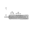
- FIG. 1 schematically shows a cross section of an example of the electrolytic capacitor 100 of the first embodiment.
- FIG. 2 shows a schematic view of a part of the capacitor element included in the electrolytic capacitor 100 shown in FIG.
- the electrolytic capacitor 100 includes, for example, a capacitor element 10, a bottomed case 11 for accommodating the capacitor element 10, a sealing member 12 for closing the opening of the bottomed case 11, and a sealing member 12.
- Lead tabs 15A and 15B (not shown) that connect the seat plate 13 that covers, the lead wires 14A and 14B that are led out from the sealing member 12 and penetrate the seat plate 13, and the lead wires 14A and 14B and the electrodes of the capacitor element 10.
- the capacitor element 10 is housed in the bottomed case 11.
- the liquid component (L) is also housed in the bottomed case 11.
- the vicinity of the open end of the bottomed case 11 is drawn inward, and the open end is curled so as to crimp the sealing member 12.
- the capacitor element 10 includes an anode body 21 having a dielectric layer on its surface, a cathode body 22, and a separator 23 arranged between them. These constitute an electrode group (winding body) 20.
- the capacitor element 10 includes an electrolyte layer (not shown) arranged between the anode body 21 and the cathode body 22.
- the anode body 21 and the cathode body 22 are wound with the separator 23 arranged between them.
- the outermost circumference of the winding body is fixed by the winding stop tape 24. Note that FIG. 2 shows a partially unfolded state before fixing the outermost circumference of the wound body.
- the electrolyte layer has uneven distribution portions in which the hydroxyl group-containing compound (C) is unevenly distributed at both ends of the winding body in the winding axis direction and the outermost peripheral portion of the winding body.
- FIG. 3 schematically shows a cross section of the capacitor element 210 of the electrolytic capacitor according to the second embodiment.
- the capacitor element 210 includes an anode portion 220 and a cathode portion 230.
- the anode portion 220 includes an anode body 221 and an anode wire 222.
- the anode body 221 includes a dielectric layer 221a formed on the surface thereof. A part of the anode wire 222 is embedded in the anode body 221.
- the cathode portion 230 has an electrolyte layer (for example, a solid electrolyte layer) 231 that covers at least a part of the dielectric layer 221a, and a cathode layer 232 that covers the electrolyte layer 231.
- an electrolyte layer for example, a solid electrolyte layer
- a cathode layer 232 that covers the electrolyte layer 231.
- the anode wire 222 is made of a conductive material.
- the material of the anode wire 222 is not particularly limited, and may be the above-mentioned valve acting metal or another metal (copper, aluminum, aluminum alloy, etc.).
- the anode portion 220 In an example of manufacturing the anode portion 220, first, a part of the anode wire 222 is embedded in a metal powder (raw material of the anode body 221), and the powder is pressure-molded into a rectangular parallelepiped shape. Next, the powder is sintered. In this way, the anode body 221 before forming the dielectric layer 221a is obtained.
- the method for forming the dielectric layer 221a is not limited, and a known method may be used for forming the dielectric layer 221a.
- the dielectric layer 221a may be formed by immersing the anode body 221 in the chemical conversion liquid and anodizing the surface of the anode body 221. Alternatively, the dielectric layer 221a may be formed by heating the anode body 221 in an atmosphere containing oxygen.
- the method for forming the electrolyte layer 231 and the cathode layer 232 is not limited, and the electrolyte layer 231 and the cathode layer 232 may be formed by the above method or a known method.
- the capacitor element 210 is connected with lead wires and sealed with an insulating material (for example, an insulating resin), if necessary. These are not limited, and known techniques can be applied. In this way, a second electrolytic capacitor is obtained.
- an insulating material for example, an insulating resin
- capacitors A1 and A2 and capacitors C1 to C4 were prepared and evaluated.
- the manufacturing method and evaluation method of these capacitors will be described below.
- conditions different from the conditions of the above-mentioned steps (ii) and (iii) may be used, but for convenience, they are also used in the steps (ii) and (iii). It is explained as.
- the capacitor A1 is a winding type electrolytic capacitor (diameter 10 mm ⁇ length 10 mm) having a rated voltage of 35 V and a rated capacitance of 270 ⁇ F.
- the capacitor A1 was manufactured by the following procedure.
- An Al foil having a thickness of 120 ⁇ m was prepared.
- the Al foil was subjected to a direct current etching treatment to roughen the surface.
- the Al foil was subjected to chemical conversion treatment to form a dielectric layer (thickness: about 70 nm) to obtain an anode body.
- the dielectric layer was formed by immersing an Al foil in an ammonium adipate solution and performing a chemical conversion treatment at 70 ° C. for 5 hours while applying a voltage of 50 V to the Al foil.
- the anode body of the capacitor A1 was prepared by cutting the anode body to a predetermined size.
- Step (i)) An anode lead tab and a cathode lead tab to which a lead wire was connected were connected to the prepared anode body and cathode body, respectively. Then, the anode body and the cathode body were wound with a separator in between, and the outer surface was fixed with a winding stopper tape. As the separator, a non-woven fabric made of aramid (aromatic polyamide fiber), which is a synthetic fiber, was used. In this way, a wound body (capacitor element precursor) was produced. The prepared winding body was immersed in an ammonium adipate solution, and the anode body was subjected to chemical conversion treatment again at 70 ° C. for 60 minutes while applying a voltage of 50 V to the anode body. Formed a body layer.
- aramid aromatic polyamide fiber
- aqueous treatment solution An aqueous solution of mannitol having a concentration of 10% by mass was prepared by dissolving mannitol in ion-exchanged water. The viscosity of the obtained aqueous mannitol solution was measured and found to be 5 mPa ⁇ s or less.
- PEDOT polystyrene sulfonic acid
- PEDOT: PSS polystyrene sulfonic acid
- dispersion liquid in which PEDOT: PSS is dispersed may be referred to as "PEDOT: PSS dispersion liquid”.
- an aqueous dispersion having a PEDOT: PSS concentration of 2% by mass was prepared. The viscosity of the obtained dispersion was measured and found to be 25 mPa ⁇ s.
- an aqueous treatment liquid was placed in a container.
- the wound body (capacitor element precursor) was immersed in the aqueous treatment liquid in the container at room temperature under an atmospheric pressure atmosphere for 5 minutes.
- the wound body was immersed in the aqueous treatment liquid from the side to which the lead tab was not connected (the same applies to the other immersion steps described below).
- the wound body was pulled up from the aqueous treatment liquid.
- the wound body was impregnated with the aqueous treatment liquid.
- the wound body was dried at 125 ° C. for 30 minutes in a drying oven having a pressure of 1 atm, whereby the aqueous treatment liquid was dried.
- mannitol which is a hydroxyl group-containing compound (C)
- the electrolyte layer had uneven distribution portions where mannitol was unevenly distributed at both ends of the winding body in the winding axis direction and at the outermost peripheral portion of the winding body.
- Step (iii) First, an aqueous dispersion was placed in a container. Next, the winding body was immersed in the aqueous dispersion in the container for 15 minutes in a reduced pressure atmosphere (40 kPa) at room temperature, and then the winding body was pulled up from the aqueous dispersion. In this way, the wound body was impregnated with the aqueous dispersion. Next, the wound body was dried at 150 ° C. for 30 minutes in a drying oven having a pressure of 1 atm. As a result, the aqueous dispersion was dried. In this way, the conductive polymer layer was formed.
- a reduced pressure atmosphere 40 kPa
- step (iii) The wound body that had undergone step (iii) was impregnated with an electrolytic solution at room temperature in an atmospheric pressure atmosphere.
- a solution mixed at a mass ratio of 25:25 was used. In this way, a capacitor element including an electrolyte layer was obtained. This capacitor element was sealed to complete an electrolytic capacitor. Then, while applying the rated voltage, the aging treatment was carried out at 130 ° C. for 2 hours. In this way, the capacitor A1 was obtained.
- Capacitor A2 The capacitor A2 was manufactured under the same conditions as the capacitor A1 except that the separator was changed. Cellulose-based natural fibers were used as the separator.
- Capacitor C1 The capacitor C1 was manufactured under the same conditions as the capacitor A1 except that the step (ii) was not performed and the conditions of the step (iii) were changed.
- an aqueous dispersion was prepared by dissolving mannitol in the PEDOT: PSS dispersion described in the preparation of the capacitor A1.
- the concentration of PEDOT: PSS in the aqueous dispersion was 2% by mass, and the concentration of mannitol was 10% by mass.
- the viscosity of the obtained dispersion was measured and found to be 45 mPa ⁇ s.
- step (iii) of the capacitor A1 Using this aqueous dispersion, impregnation was performed under the same conditions as in step (iii) of the capacitor A1. Next, in the drying oven, the wound body was dried at 60 ° C. for 30 minutes, followed by drying at 125 ° C. for 15 minutes. This dried the aqueous dispersion. In this way, the conductive polymer layer was formed. After that, the capacitor C1 was manufactured in the same process as the capacitor A1.
- Capacitor C2 The capacitor C2 was manufactured under the same conditions as the capacitor A1 except that the drying temperature in the step (ii) and the drying temperature and time in the step (iii) were changed. In the step (ii) of the capacitor C2, drying was performed at 180 ° C. for 30 minutes. In the step (iii) of the capacitor C2, the capacitor C2 was dried at 60 ° C. for 30 minutes, and then dried at 125 ° C. for 15 minutes.
- Capacitor C3 The capacitor C3 was manufactured under the same conditions as the capacitor C2 except that the step (ii) was not performed.
- Capacitor C4 The capacitor C4 was manufactured under the same conditions as the capacitor C2 except that the separator was changed. Cellulose-based natural fibers were used as the separator.
- Step (ii) was carried out in the same manner as the method for manufacturing each capacitor described above. Then, the wound body (capacitor element precursor) that had undergone step (ii) was decomposed, and the distribution of mannitol in the electrolyte layer was investigated. Specifically, the identification of mannitol was carried out using a microscopic FT-IR analyzer (Nicolet-iN10 manufactured by Thermo Fisher). Regarding the distribution ratio of mannitol, first, the end portion of the device and the center portion of the device were separated, and the mannitol adhering to each was extracted with an aqueous solvent. Next, the dry weight of mannitol present in each portion was determined.
- step (iii) was carried out in the same manner as in the above-mentioned method for producing each capacitor, and the distribution ratio of mannitol in the electrolyte layer was determined.
- ESR Equivalent series resistance
- Table 1 shows the measurement results and some of the manufacturing conditions for electrolytic capacitors.
- PEDOT: PSS mixture means that the aqueous dispersion is a dispersion containing PEDOT: PSS and mannitol.
- the drying temperature of the steps (ii-b) of the capacitors A1 and A2 is equal to or higher than the boiling point of the aqueous treatment liquid.
- the melting point of mannitol is about 165 to 169 ° C. Therefore, the drying temperature of the steps (ii-b) of the capacitors A1 and A2 is equal to or higher than the boiling point of the aqueous treatment liquid and lower than the melting point of mannitol (hydroxyl-containing compound (C)).
- the drying temperature of the steps (ii-b) of the capacitors C2 and C4 is higher than the melting point of mannitol (hydroxyl-containing compound (C)).
- the ESR value is preferably 20 m ⁇ or less (for example, in the range of 3 to 20 m ⁇ ), and more preferably 12 m ⁇ or less (for example, in the range of 3 to 12 m ⁇ ).
- the breakdown withstand voltage is preferably high, and is preferably 75 V or higher (for example, in the range of 75 to 100 V).
- the number of short circuits is preferably small.
- the capacitors A1 and A2 of the present disclosure had good ESR, breakdown withstand voltage, and number of short circuits. It is considered that the low ESR is due to the fact that the electrolyte layer contains mannitol (hydroxyl group-containing compound (C)). It is considered that the reason why the breakdown withstand voltage and the number of short circuits are low is that mannitol is unevenly distributed at both ends of the winding body in the winding axis direction and the outermost peripheral portion of the winding body.
- This disclosure can be used for electrolytic capacitors and methods for manufacturing them.
Landscapes
- Engineering & Computer Science (AREA)
- Power Engineering (AREA)
- Chemical & Material Sciences (AREA)
- Chemical Kinetics & Catalysis (AREA)
- Electrochemistry (AREA)
- Microelectronics & Electronic Packaging (AREA)
- Manufacturing & Machinery (AREA)
- Electric Double-Layer Capacitors Or The Like (AREA)
- Compositions Of Macromolecular Compounds (AREA)
- Materials Engineering (AREA)
Priority Applications (3)
| Application Number | Priority Date | Filing Date | Title |
|---|---|---|---|
| JP2021574698A JP7681840B2 (ja) | 2020-01-30 | 2021-01-29 | 電解コンデンサおよびその製造方法 |
| CN202180011047.6A CN115023779B (zh) | 2020-01-30 | 2021-01-29 | 电解电容器及其制造方法 |
| US17/813,605 US12119185B2 (en) | 2020-01-30 | 2022-07-20 | Electrolytic capacitor and method for producing same |
Applications Claiming Priority (2)
| Application Number | Priority Date | Filing Date | Title |
|---|---|---|---|
| JP2020-013195 | 2020-01-30 | ||
| JP2020013195 | 2020-01-30 |
Related Child Applications (1)
| Application Number | Title | Priority Date | Filing Date |
|---|---|---|---|
| US17/813,605 Continuation US12119185B2 (en) | 2020-01-30 | 2022-07-20 | Electrolytic capacitor and method for producing same |
Publications (1)
| Publication Number | Publication Date |
|---|---|
| WO2021153749A1 true WO2021153749A1 (ja) | 2021-08-05 |
Family
ID=77079162
Family Applications (1)
| Application Number | Title | Priority Date | Filing Date |
|---|---|---|---|
| PCT/JP2021/003297 Ceased WO2021153749A1 (ja) | 2020-01-30 | 2021-01-29 | 電解コンデンサおよびその製造方法 |
Country Status (4)
| Country | Link |
|---|---|
| US (1) | US12119185B2 (https=) |
| JP (1) | JP7681840B2 (https=) |
| CN (1) | CN115023779B (https=) |
| WO (1) | WO2021153749A1 (https=) |
Families Citing this family (1)
| Publication number | Priority date | Publication date | Assignee | Title |
|---|---|---|---|---|
| JP7724421B2 (ja) * | 2020-01-30 | 2025-08-18 | パナソニックIpマネジメント株式会社 | 電解コンデンサおよびその製造方法 |
Citations (8)
| Publication number | Priority date | Publication date | Assignee | Title |
|---|---|---|---|---|
| JP2008235908A (ja) * | 2007-03-21 | 2008-10-02 | Avx Corp | 保護接着剤層を含有する固体電解コンデンサ |
| JP2011014590A (ja) * | 2009-06-30 | 2011-01-20 | Sanyo Electric Co Ltd | 固体電解コンデンサの製造方法 |
| WO2012137969A1 (ja) * | 2011-04-08 | 2012-10-11 | Necトーキン株式会社 | 導電性高分子溶液、導電性高分子材料およびその製造方法、並びに固体電解コンデンサ |
| JP2013138145A (ja) * | 2011-12-28 | 2013-07-11 | Nippon Chemicon Corp | 固体電解コンデンサの製造方法 |
| JP2014007422A (ja) * | 2013-09-12 | 2014-01-16 | Shin Etsu Polymer Co Ltd | 固体電解キャパシタ及びその製造方法 |
| JP2014082392A (ja) * | 2012-10-18 | 2014-05-08 | Tayca Corp | 電解コンデンサの製造方法 |
| JP2014090107A (ja) * | 2012-10-31 | 2014-05-15 | Tayca Corp | 電解コンデンサの製造方法 |
| JP2017118051A (ja) * | 2015-12-25 | 2017-06-29 | 株式会社トーキン | 固体電解コンデンサ及びその製造方法 |
Family Cites Families (13)
| Publication number | Priority date | Publication date | Assignee | Title |
|---|---|---|---|---|
| US2739275A (en) * | 1952-06-20 | 1956-03-20 | Bell Telephone Labor Inc | Stabilization of electrolytic capacitors |
| JPH02230708A (ja) * | 1989-03-03 | 1990-09-13 | Nitsuko Corp | 固体電解コンデンサ |
| JP2004095696A (ja) * | 2002-08-30 | 2004-03-25 | Fujitsu Media Device Kk | 固体電解コンデンサの製造方法 |
| JP2004186684A (ja) * | 2002-11-21 | 2004-07-02 | Showa Denko Kk | 固体電解コンデンサ及びその製造方法 |
| JP5305569B2 (ja) | 2006-06-29 | 2013-10-02 | 三洋電機株式会社 | 電解コンデンサの製造方法および電解コンデンサ |
| JP2011082313A (ja) | 2009-10-06 | 2011-04-21 | Shin Etsu Polymer Co Ltd | 固体電解キャパシタ及びその製造方法 |
| JP5492595B2 (ja) * | 2010-02-22 | 2014-05-14 | 信越ポリマー株式会社 | キャパシタ及びその製造方法 |
| US8771381B2 (en) * | 2011-02-15 | 2014-07-08 | Kemet Electronics Corporation | Process for producing electrolytic capacitors and capacitors made thereby |
| JP2012191178A (ja) | 2011-02-22 | 2012-10-04 | Sanyo Electric Co Ltd | 電解コンデンサおよび電解コンデンサの製造方法 |
| JP2014123685A (ja) * | 2012-12-21 | 2014-07-03 | Nippon Chemicon Corp | 電解コンデンサ及びその製造方法 |
| JP6467782B2 (ja) * | 2014-04-29 | 2019-02-13 | 日本ケミコン株式会社 | 固体電解コンデンサ及びその製造方法 |
| JP2017220679A (ja) * | 2017-08-22 | 2017-12-14 | 日本ケミコン株式会社 | 電解コンデンサ及びその製造方法 |
| EP3828906B1 (en) * | 2018-07-26 | 2025-09-03 | Sun Electronic Industries Corp. | Electrolytic capacitor |
-
2021
- 2021-01-29 CN CN202180011047.6A patent/CN115023779B/zh active Active
- 2021-01-29 WO PCT/JP2021/003297 patent/WO2021153749A1/ja not_active Ceased
- 2021-01-29 JP JP2021574698A patent/JP7681840B2/ja active Active
-
2022
- 2022-07-20 US US17/813,605 patent/US12119185B2/en active Active
Patent Citations (8)
| Publication number | Priority date | Publication date | Assignee | Title |
|---|---|---|---|---|
| JP2008235908A (ja) * | 2007-03-21 | 2008-10-02 | Avx Corp | 保護接着剤層を含有する固体電解コンデンサ |
| JP2011014590A (ja) * | 2009-06-30 | 2011-01-20 | Sanyo Electric Co Ltd | 固体電解コンデンサの製造方法 |
| WO2012137969A1 (ja) * | 2011-04-08 | 2012-10-11 | Necトーキン株式会社 | 導電性高分子溶液、導電性高分子材料およびその製造方法、並びに固体電解コンデンサ |
| JP2013138145A (ja) * | 2011-12-28 | 2013-07-11 | Nippon Chemicon Corp | 固体電解コンデンサの製造方法 |
| JP2014082392A (ja) * | 2012-10-18 | 2014-05-08 | Tayca Corp | 電解コンデンサの製造方法 |
| JP2014090107A (ja) * | 2012-10-31 | 2014-05-15 | Tayca Corp | 電解コンデンサの製造方法 |
| JP2014007422A (ja) * | 2013-09-12 | 2014-01-16 | Shin Etsu Polymer Co Ltd | 固体電解キャパシタ及びその製造方法 |
| JP2017118051A (ja) * | 2015-12-25 | 2017-06-29 | 株式会社トーキン | 固体電解コンデンサ及びその製造方法 |
Also Published As
| Publication number | Publication date |
|---|---|
| JPWO2021153749A1 (https=) | 2021-08-05 |
| US20220375693A1 (en) | 2022-11-24 |
| CN115023779A (zh) | 2022-09-06 |
| JP7681840B2 (ja) | 2025-05-23 |
| US12119185B2 (en) | 2024-10-15 |
| CN115023779B (zh) | 2025-03-11 |
Similar Documents
| Publication | Publication Date | Title |
|---|---|---|
| US11094471B2 (en) | Electrolytic capacitor | |
| JP6803519B2 (ja) | 電解コンデンサの製造方法 | |
| JP7689321B2 (ja) | 電解コンデンサおよびその製造方法 | |
| US12417883B2 (en) | Electrolytic capacitor and method for manufacturing same | |
| JP7731057B2 (ja) | 電解コンデンサおよびその製造方法 | |
| US20250054706A1 (en) | Electrolytic capacitor and method for producing same | |
| JP2025163262A (ja) | 電解コンデンサおよびその製造方法 | |
| JP7620827B2 (ja) | 電解コンデンサおよびその製造方法 | |
| CN107430940B (zh) | 电解电容器及其制造方法 | |
| US12424390B2 (en) | Electrolytic capacitor and method for producing same | |
| US12119185B2 (en) | Electrolytic capacitor and method for producing same | |
| JP2017175082A (ja) | 電解コンデンサおよびその製造方法 | |
| US20260038745A1 (en) | Dispersion for use in manufacturing electrolytic capacitor, electrolytic capacitor manufacturing method, and electrolytic capacitor | |
| US20260058067A1 (en) | Electrolytic capacitor and method for manufacturing electrolytic capacitor | |
| WO2025164474A1 (ja) | 電解コンデンサおよび電解コンデンサの製造方法 |
Legal Events
| Date | Code | Title | Description |
|---|---|---|---|
| 121 | Ep: the epo has been informed by wipo that ep was designated in this application |
Ref document number: 21747417 Country of ref document: EP Kind code of ref document: A1 |
|
| ENP | Entry into the national phase |
Ref document number: 2021574698 Country of ref document: JP Kind code of ref document: A |
|
| NENP | Non-entry into the national phase |
Ref country code: DE |
|
| 122 | Ep: pct application non-entry in european phase |
Ref document number: 21747417 Country of ref document: EP Kind code of ref document: A1 |
|
| WWG | Wipo information: grant in national office |
Ref document number: 202180011047.6 Country of ref document: CN |