WO2021152859A1 - Terminal et procédé de communication - Google Patents
Terminal et procédé de communication Download PDFInfo
- Publication number
- WO2021152859A1 WO2021152859A1 PCT/JP2020/003822 JP2020003822W WO2021152859A1 WO 2021152859 A1 WO2021152859 A1 WO 2021152859A1 JP 2020003822 W JP2020003822 W JP 2020003822W WO 2021152859 A1 WO2021152859 A1 WO 2021152859A1
- Authority
- WO
- WIPO (PCT)
- Prior art keywords
- signal
- lte
- terminal
- qcl
- base station
- Prior art date
Links
Images


Classifications
-
- H—ELECTRICITY
- H04—ELECTRIC COMMUNICATION TECHNIQUE
- H04W—WIRELESS COMMUNICATION NETWORKS
- H04W16/00—Network planning, e.g. coverage or traffic planning tools; Network deployment, e.g. resource partitioning or cells structures
- H04W16/14—Spectrum sharing arrangements between different networks
-
- H—ELECTRICITY
- H04—ELECTRIC COMMUNICATION TECHNIQUE
- H04W—WIRELESS COMMUNICATION NETWORKS
- H04W48/00—Access restriction; Network selection; Access point selection
- H04W48/18—Selecting a network or a communication service
-
- H—ELECTRICITY
- H04—ELECTRIC COMMUNICATION TECHNIQUE
- H04W—WIRELESS COMMUNICATION NETWORKS
- H04W56/00—Synchronisation arrangements
Definitions
- the present invention relates to a terminal and a communication method in a wireless communication system.
- Non-Patent Document 1 NR (New Radio) (also called “5G”), which is the successor system to LTE (Long Term Evolution), the requirements are a large-capacity system, high-speed data transmission speed, low delay, and simultaneous operation of many terminals. Techniques that satisfy connection, low cost, power saving, etc. are being studied (for example, Non-Patent Document 1).
- DSS Dynamic spectrum sharing
- RATs Radio Access Technology
- signals for synchronization are transmitted to LTE terminals and NR terminals, respectively. That is, since signals having the same function are transmitted to each RAT (Radio Access Technology), the overhead in the entire system increases.
- RAT Radio Access Technology
- the present invention has been made in view of the above points, and an object of the present invention is to reduce the overhead when a plurality of RATs (Radio Access Technology) coexist in a single carrier in a wireless communication system.
- RATs Radio Access Technology
- a QCL Quadrature- of a receiving unit that receives the first signal of the first RAT (Radio Access Technology), the first signal, and the second signal of the second RAT.
- a terminal having a control unit that synchronizes with the cell of the second RAT is provided by using a co-location) relationship.
- LTE Long Term Evolution
- LTE-Advanced LTE-Advanced and later methods (eg, NR) unless otherwise specified.
- SS Synchronization signal
- PSS Primary SS
- SSS Secondary SS
- PBCH Physical broadcast channel
- PRACH Physical
- PDCCH Physical Downlink Control Channel
- PDSCH Physical Downlink Shared Channel
- PUCCH Physical Uplink Control Channel
- PUSCH Physical Uplink Shared Channel
- NR corresponds to NR-SS, NR-PSS, NR-SSS, NR-PBCH, NR-PRACH and the like. However, even if it is a signal used for NR, it is not always specified as "NR-".
- the duplex system may be a TDD (Time Division Duplex) system, an FDD (Frequency Division Duplex) system, or other system (for example, Flexible Duplex, etc.). Method may be used.
- TDD Time Division Duplex
- FDD Frequency Division Duplex
- Method may be used.
- "configuring" the radio parameter or the like may mean that a predetermined value is set in advance (Pre-configure), or the base station 10 or The radio parameter notified from the terminal 20 may be set.
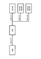
- FIG. 1 is a diagram showing a configuration example of a wireless communication system according to the embodiment of the present invention.
- the wireless communication system according to the embodiment of the present invention includes a base station 10 and a terminal 20 as shown in FIG.
- FIG. 1 shows one base station 10 and one terminal 20, this is an example, and there may be a plurality of each.
- the base station 10 is a communication device that provides one or more cells and performs wireless communication with the terminal 20.
- the physical resources of the radio signal are defined in the time domain and the frequency domain, the time domain may be defined by the number of OFDM (Orthogonal Frequency Division Multiplexing) symbols, and the frequency domain is defined by the number of subcarriers or the number of resource blocks. May be good.
- the base station 10 transmits a synchronization signal and system information to the terminal 20. Synchronous signals are, for example, NR-PSS and NR-SSS.
- the system information is transmitted by, for example, NR-PBCH, and is also referred to as broadcast information.
- the synchronization signal and system information may be referred to as SSB (SS / PBCH block).
- the base station 10 transmits a control signal or data to the terminal 20 by DL (Downlink), and receives the control signal or data from the terminal 20 by UL (Uplink). Both the base station 10 and the terminal 20 can perform beamforming to transmit and receive signals. Further, both the base station 10 and the terminal 20 can apply MIMO (Multiple Input Multiple Output) communication to DL or UL. Further, both the base station 10 and the terminal 20 may communicate via a secondary cell (SCell: Secondary Cell) and a primary cell (PCell: Primary Cell) by CA (Carrier Aggregation). Further, the terminal 20 may perform communication via the primary cell of the base station 10 by DC (Dual Connectivity) and the primary secondary cell (PSCell: Primary Secondary Cell) of another base station 10.
- SCell Secondary Cell
- PCell Primary Cell
- CA Carrier Aggregation
- the terminal 20 is a communication device having a wireless communication function such as a smartphone, a mobile phone, a tablet, a wearable terminal, and a communication module for M2M (Machine-to-Machine). As shown in FIG. 1, the terminal 20 receives a control signal or data from the base station 10 on the DL and transmits the control signal or data to the base station 10 on the UL, thereby providing various types provided by the wireless communication system. Use communication services. Further, the terminal 20 receives various reference signals transmitted from the base station 10 and executes the measurement of the propagation path quality based on the reception result of the reference signals.
- M2M Machine-to-Machine
- DSS Dynamic Spectrum Sharing
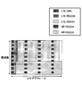
- FIG. 2 is a diagram showing an example of downlink channel arrangement by DSS.
- the time domain shown in FIG. 2 corresponds to one LTE subframe.
- LTE-CRS Cell specific reference signal
- LTE-PDCCH LTE-PDCCH
- LTE-PDSCH LTE signals or channels on the downlink.
- NR-PDSCH may include a resource in which DM-RS (Demodulation reference signal) is arranged.
- LTE-CRS may be arranged in the "NR-PDSCH” region.
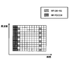
- FIG. 3 is a diagram showing an example of uplink channel arrangement by DSS.
- LTE and NR uplink channels or signals are arranged sharing a frequency band.
- FIG. 3 for example, from low frequency to high frequency, "NR-PUCCH”, “LTE-PUCCH”, “LTE-PRACH”, “LTE-PUSCH”, “NR-PUSCH”, “NR-” It is arranged in the order of "PRACH”, “LTE-PUSCH”, “LTE-PUCCH”, and “NR-PUCCH”.
- LTE-SRS Sounding Reference Signal
- NR-SRS may be arranged in the frequency domain in which "LTE-PUSCH", “NR-PUSCH” and “NR-PRACH” are arranged.
- LTE and NR are frequency-multiplexed
- other multiplexing methods may be used, for example, time-multiplexed or spatial-multiplexed.
- FIG. 4 is a diagram showing an example (1) of frequency allocation in DSS.
- the BS Base station
- the BS provides LTE for carrier # 1, LTE and NR for carrier # 2, NR for carrier # 3, and NR for carrier # 4.
- the carrier # 1 is an LTE PCell (Primary Cell)
- the carrier # 2 is an NR PSCell (Primary Secondary Cell)
- SCell Secondary Cell
- SCell Secondary Cell
- SCell may be arranged in # 3
- SCell may be arranged in carrier # 4.
- the SCell is arranged on the carrier # 4
- the SCell is arranged on the carrier # 4
- the SCell is arranged on the carrier # 4 as in the pattern 2 shown in FIG. good.
- a PCell of NR may be arranged in carrier # 2
- SCell in carrier # 3 as in pattern 3 shown in FIG.
- the LTE PCell may be arranged on the carrier # 1 as in pattern 1 shown in FIG. Further, for example, for the LTE UE, the LTE PCell may be arranged on the carrier # 2 as in the pattern 2 shown in FIG. Further, for example, the LTE PCell may be arranged on the carrier # 1 and the LTE SCell may be arranged on the carrier # 2 as in the pattern 3 shown in FIG. 4 for the LTE UE. Further, for example, the LTE SCell may be arranged on the carrier # 1 and the LTE PCell may be arranged on the carrier # 2 as in the pattern 4 shown in FIG. 4 for the LTE UE.
- FIG. 5 is a diagram showing an example (2) of frequency allocation in DSS. As shown in FIG. 5, the BS provides LTE and NR in carrier # 1, NR in carrier # 2, and NR in carrier # 3.
- LTE PCell and NR SCell are arranged in carrier # 1
- NR PSCell is arranged in carrier # 2
- NR SCell is arranged in carrier # 3.
- the carrier # 1 has the LTE PCell and the NR PSCell
- the carrier # 2 has the NR PSCell
- the carrier # 3 has the NR SCell. It may be arranged.
- a PCell of NR is arranged in carrier # 1
- a PSCell of NR is arranged in carrier # 2
- a SCell of NR is arranged in carrier # 3, as in pattern 3 shown in FIG. good.
- the LTE PCell may be arranged on the carrier # 1 as in pattern 1 shown in FIG.
- Table 1 is an example showing LTE and NR synchronization signals or reference signals for each purpose.
- LTE and NR signals are specified for the same or similar purposes, respectively.
- the purpose may mean an application.
- LTE-PSS / SSS is used for LTE
- NR-PSS / SSS is used for NR.
- CRS is used for LTE
- NR-TRS is used for NR.
- NR-TRS may be referred to as NR-CSI (Channel State Information) -RS for tracking.
- LTE-CRS / CSI-RS is used for LTE
- NR-CSI-RS is used for NR.
- LTE-SRS is used for LTE and NR-SRS is used for NR for upstream propagation path estimation.
- a signal for the purpose is not set in LTE, and NR-PT (Phase tracking) -RS is used in NR.
- LTE-CRS / DM-RS is used for LTE
- NR-DM-RS is used for NR.
- CRS is used for LTE and NR-PBCH-DM-RS is used for NR for decoding the broadcast signal.
- the physical signal configuration may be different.
- LTE CSI-RS and NR CSI-RS have different physical signal configurations.
- FIG. 6 is a diagram showing an example of channel arrangement of the LTE downlink.
- the time domain shown in FIG. 6 corresponds to one LTE subframe, and the frequency domain corresponds to one resource block.
- LTE-CRS is transmitted as a reference signal and LTE-PDCCH is transmitted as a control signal.
- FIG. 7 is a diagram showing an example of channel arrangement of the NR downlink.
- the time domain shown in FIG. 7 corresponds to one slot of NR, the frequency domain corresponds to one resource block, and the subcarrier interval is 15 kHz.
- NR-DM-RS is transmitted as a reference signal and NR-PDCCH is transmitted as a control signal.
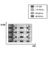
- FIG. 8 is a diagram showing an example of channel arrangement of LTE and NR downlinks by DSS. Under the current DSS specifications, signals for the same purpose are transmitted to LTE terminals and NR terminals, respectively. As shown in FIG. 8, when the LTE signal and the NR signal are transmitted, respectively, the overhead increases and the resource for transmitting data decreases.
- the terminal 20 may receive an NR signal / channel using LTE-CRS. Further, for example, the terminal 20 may use LTE-SS to establish synchronization with the NR cell.
- QCL Quadrature-co-location
- QCL type A relates to Doppler shifts, Doppler spreads, average delays, delay rates.
- QCL type B relates to Doppler shifts and Doppler spreads.
- QCL type C relates to Doppler shift, average delay.
- the QCL type D relates to a spatial reception parameter (Spatial Rx parameter). Therefore, QCL type A, B or C is QCL information related to time or frequency synchronization processing, and QCL type D is QCL information related to beam control.
- a certain SS block and a certain CSI-RS are QCL type D
- the terminal 20 transmits the SS block and the CSI-RS from the base station 10 with the same DL beam. Therefore, the same reception beamforming can be applied to receive the signal.
- the "QCL type D" will be mainly described, but the QCL type A, B or C may be substituted as appropriate.
- time synchronization, frequency synchronization, and beam control may be referred to as "synchronization” or "synchronization processing” without distinction.
- FIG. 9 is a diagram showing an example of the QCL relationship between the reference signals.
- a QCL is defined between two signals and is defined as a QCL when the radio parameters between the signals can be considered to be the same.
- FIG. 9 shows an example of a QCL association.
- the QCL relationship there is a parent-child relationship of source and destination.
- the source of QCL types C and D is SSB
- the destination is TRS (Tracking Reference Signal or CSI-RS for tracking).
- the sources of QCL types A and D are TRS
- the destinations are CSI-RS, PDCCH DM-RS (Demodulation reference signal) and PDSCH DM-RS.
- information indicating the QCL source signal is notified to a certain signal.
- the base station 10 notifies the terminal 20 of the destination TRS that the QCL types C and D are sourced from the SSB.
- Signaling for notifying information about the QCL may be executed by a TCI (Transmission configuration indicator).
- FIG. 10 is a flowchart for explaining an operation example related to synchronization in the embodiment of the present invention.
- the terminal 20 starts the NR cell addition operation.
- the terminal 20 synchronizes with the NR cell using the LTE signal.
- the terminal 20 may utilize a QCL setting in which the LTE signal is the source and the NR signal is the destination.
- FIG. 11 is a flowchart for explaining an operation example related to the QCL setting in the embodiment of the present invention.
- a QCL setting is performed in which the LTE signal is used as the QCL source and the NR signal is used as the QCL destination.
- the QCL setting may be notified from the base station 10 to the terminal 20.
- the terminal 20 synchronizes with the NR cell using the QCL setting (S22).
- LTE signals A) -D) may be used as the QCL source.
- A) SS (PSS and part or all of SSS) B) PBCH reference signal C) CRS D) CSI-RS E) DM-RS
- NR signals a) -d) may be used as the QCL source.
- SSB (some or all of PSS, SSS, PBCH-DM-RS)
- DM-RS (PDSCH DM-RS, part or all of PDCCH DM-RS)
- CSI-RS d) TRS (CSI-RS for tracking)
- the definition of QCL relations described above may be as shown in 1) -3) below.
- the QCL relationship may include some or all of the QCL types A, B, C and D defined by the NR.
- the QCL relationship may be defined as the QCL defined by LTE.
- Parameters related to QCL may include some or all of delay spread, Doppler spread, Doppler shift, average gain, average delay, spatial Rx parameter. good.
- the parameters related to the QCL may be newly defined parameters other than those described above.
- the terminal 20 may assume that the reference signal of the same type is a QCL by default.
- LTE-PSS / SSS may be assumed to be NR-PSS / SSS and QCL.
- LTE-CRS may be assumed to be NR-TRS and QCL.
- the embodiment of the present invention has been described as a main example when the first RAT and the second RAT are DSS, but it does not necessarily have to be DSS.
- the second RAT may establish a QCL based on the signal of the first RAT.
- the embodiment of the present invention can be applied regardless of the distinction between uplink, downlink, transmission or reception.
- the uplink signal and channel and the downlink signal and channel can be read interchangeably.
- Upstream feedback information and downlink control signaling can be read interchangeably.
- the signaling from the base station 10 to the terminal 20 or the signaling from the terminal 20 to the base station 10 in the above-described embodiment is not limited to an explicit method, and may be notified by an implicit method. good. In addition, signaling is not performed and may be uniquely specified in the specifications.
- the signaling from the base station 10 to the terminal 20 or the signaling from the terminal 20 to the base station 10 in the above-described embodiment may be different layers of signaling such as RRC signaling, MAC-CE signaling, or DCI signaling.
- Signaling by broadcast information MIB (Master Information Block), SIB (System Information Block)
- MIB Master Information Block
- SIB System Information Block
- RRC signaling and DCI signaling may be combined, RRC signaling and MAC-CE signaling may be combined, or RRC signaling, MAC-CE signaling, and DCI signaling may be combined.
- the next generation system may receive the signals and / or channels of the previous generation system.
- the system may span multiple generations.
- one system may apply the reference signal of a system two generations ago. Multiple generations of reference signals may be applied.
- synchronization may apply the reference signal of the system two generations ago, and data decoding may apply the reference signal of the system one generation ago.
- the application of this technology does not have to be the difference in RAT between generations before and after. That is, in general, it may be applied in different RATs.
- the past system applies the signals and / or channels of the past system, but conversely, the past system may apply the signals and / or channels of the future system.
- the "data” in the above-described embodiment may indicate PDSCH, PDCCH, or PBCH.
- the “data” may also indicate uplink signals and / or channels.
- the terminal 20 can reduce the amount of signals related to the synchronization of NR by synchronizing the NR using the LTE signal.
- the base station 10 and the terminal 20 include a function of carrying out the above-described embodiment.
- the base station 10 and the terminal 20 may each have only a part of the functions in the embodiment.
- FIG. 12 is a diagram showing an example of the functional configuration of the base station 10 according to the embodiment of the present invention.
- the base station 10 includes a transmission unit 110, a reception unit 120, a setting unit 130, and a control unit 140.
- the functional configuration shown in FIG. 12 is only an example. Any function classification and name of the functional unit may be used as long as the operation according to the embodiment of the present invention can be executed.
- the transmission unit 110 includes a function of generating a signal to be transmitted to the terminal 20 side and transmitting the signal wirelessly. Further, the transmission unit 110 transmits a message between network nodes to another network node.
- the receiving unit 120 includes a function of receiving various signals transmitted from the terminal 20 and acquiring information of, for example, a higher layer from the received signals. Further, the transmission unit 110 has a function of transmitting NR-PSS, NR-SSS, NR-PBCH, DL / UL control signals and the like to the terminal 20. In addition, the receiving unit 120 receives a message between network nodes from another network node.
- the setting unit 130 stores preset setting information and various setting information to be transmitted to the terminal 20.
- the content of the setting information is, for example, information related to the DSS setting.
- the control unit 140 controls the DSS setting as described in the embodiment. Further, the control unit 140 controls the communication by the DSS.
- the function unit related to signal transmission in the control unit 140 may be included in the transmission unit 110, and the function unit related to signal reception in the control unit 140 may be included in the reception unit 120.
- FIG. 13 is a diagram showing an example of the functional configuration of the terminal 20 according to the embodiment of the present invention.
- the terminal 20 has a transmission unit 210, a reception unit 220, a setting unit 230, and a control unit 240.
- the functional configuration shown in FIG. 13 is only an example. Any function classification and name of the functional unit may be used as long as the operation according to the embodiment of the present invention can be executed.
- the transmission unit 210 creates a transmission signal from the transmission data and wirelessly transmits the transmission signal.
- the receiving unit 220 wirelessly receives various signals and acquires a signal of a higher layer from the received signal of the physical layer. Further, the receiving unit 220 has a function of receiving NR-PSS, NR-SSS, NR-PBCH, DL / UL / SL control signals and the like transmitted from the base station 10. Further, for example, the transmission unit 210 connects the other terminal 20 to PSCCH (Physical Sidelink Control Channel), PSCH (Physical Sidelink Shared Channel), PSDCH (Physical Sidelink Discovery Channel), PSBCH (Physical Sidelink Broadcast Channel) as D2D communication. Etc., and the receiving unit 220 receives PSCCH, PSCH, PSDCH, PSBCH, etc. from the other terminal 20.
- PSCCH Physical Sidelink Control Channel
- PSCH Physical Sidelink Shared Channel
- PSDCH Physical Sidelink Discovery Channel
- PSBCH Physical Sidelink Broadcast Channel
- the setting unit 230 stores various setting information received from the base station 10 by the receiving unit 220.
- the setting unit 230 also stores preset setting information.
- the content of the setting information is, for example, information related to the DSS setting.
- the control unit 240 controls the DSS setting as described in the embodiment. Further, the control unit 240 controls the communication by the DSS.
- the function unit related to signal transmission in the control unit 240 may be included in the transmission unit 210, and the function unit related to signal reception in the control unit 240 may be included in the reception unit 220.
- each functional block may be realized by using one device that is physically or logically connected, or directly or indirectly (for example, by two or more devices that are physically or logically separated). , Wired, wireless, etc.) and may be realized using these plurality of devices.
- the functional block may be realized by combining the software with the one device or the plurality of devices.
- Functions include judgment, decision, judgment, calculation, calculation, processing, derivation, investigation, search, confirmation, reception, transmission, output, access, solution, selection, selection, establishment, comparison, assumption, expectation, and assumption. Broadcasting, notifying, communicating, forwarding, configuring, reconfiguring, allocating, mapping, assigning, etc., but limited to these I can't.
- a functional block that makes transmission function is called a transmitting unit (transmitting unit) or a transmitter (transmitter).
- transmitting unit transmitting unit
- transmitter transmitter
- the base station 10, the terminal 20, and the like in one embodiment of the present disclosure may function as a computer that processes the wireless communication method of the present disclosure.
- FIG. 14 is a diagram showing an example of the hardware configuration of the base station 10 and the terminal 20 according to the embodiment of the present disclosure.
- the above-mentioned base station 10 and terminal 20 are physically configured as a computer device including a processor 1001, a storage device 1002, an auxiliary storage device 1003, a communication device 1004, an input device 1005, an output device 1006, a bus 1007, and the like. May be good.
- the word “device” can be read as a circuit, device, unit, etc.
- the hardware configuration of the base station 10 and the terminal 20 may be configured to include one or more of the devices shown in the figure, or may be configured not to include some of the devices.
- the processor 1001 For each function of the base station 10 and the terminal 20, the processor 1001 performs an operation by loading predetermined software (program) on the hardware such as the processor 1001 and the storage device 1002, and controls the communication by the communication device 1004. It is realized by controlling at least one of reading and writing of data in the storage device 1002 and the auxiliary storage device 1003.
- Processor 1001 operates, for example, an operating system to control the entire computer.
- the processor 1001 may be composed of a central processing unit (CPU: Central Processing Unit) including an interface with a peripheral device, a control device, an arithmetic unit, a register, and the like.
- CPU Central Processing Unit
- control unit 140, control unit 240, and the like may be realized by the processor 1001.
- the processor 1001 reads a program (program code), a software module, data, or the like from at least one of the auxiliary storage device 1003 and the communication device 1004 into the storage device 1002, and executes various processes according to these.
- a program program that causes a computer to execute at least a part of the operations described in the above-described embodiment is used.
- the control unit 140 of the base station 10 shown in FIG. 12 may be realized by a control program stored in the storage device 1002 and operated by the processor 1001.
- the control unit 240 of the terminal 20 shown in FIG. 13 may be realized by a control program stored in the storage device 1002 and operated by the processor 1001.
- Processor 1001 may be implemented by one or more chips.
- the program may be transmitted from the network via a telecommunication line.
- the storage device 1002 is a computer-readable recording medium, for example, by at least one of ROM (Read Only Memory), EPROM (Erasable Programmable ROM), EEPROM (Electrically Erasable Programmable ROM), RAM (Random Access Memory), and the like. It may be configured.
- the storage device 1002 may be referred to as a register, a cache, a main memory (main storage device), or the like.
- the storage device 1002 can store a program (program code), a software module, or the like that can be executed to implement the communication method according to the embodiment of the present disclosure.
- the auxiliary storage device 1003 is a computer-readable recording medium, and is, for example, an optical disk such as a CD-ROM (Compact Disc ROM), a hard disk drive, a flexible disk, an optical magnetic disk (for example, a compact disk, a digital versatile disk, Blu).
- -It may be composed of at least one of a ray (registered trademark) disk), a smart card, a flash memory (for example, a card, a stick, a key drive), a floppy (registered trademark) disk, a magnetic strip, and the like.
- the storage medium described above may be, for example, a database, server or other suitable medium containing at least one of the storage device 1002 and the auxiliary storage device 1003.
- the communication device 1004 is hardware (transmission / reception device) for communicating between computers via at least one of a wired network and a wireless network, and is also referred to as, for example, a network device, a network controller, a network card, a communication module, or the like.
- the communication device 1004 includes, for example, a high frequency switch, a duplexer, a filter, a frequency synthesizer, and the like in order to realize at least one of frequency division duplex (FDD: Frequency Division Duplex) and time division duplex (TDD: Time Division Duplex). It may be composed of.
- FDD Frequency Division Duplex
- TDD Time Division Duplex
- the transmission / reception unit may be physically or logically separated from each other in the transmission unit and the reception unit.
- the input device 1005 is an input device (for example, a keyboard, a mouse, a microphone, a switch, a button, a sensor, etc.) that receives an input from the outside.
- the output device 1006 is an output device (for example, a display, a speaker, an LED lamp, etc.) that outputs to the outside.
- the input device 1005 and the output device 1006 may have an integrated configuration (for example, a touch panel).
- each device such as the processor 1001 and the storage device 1002 is connected by a bus 1007 for communicating information.
- the bus 1007 may be configured by using a single bus, or may be configured by using a different bus for each device.
- the base station 10 and the terminal 20 are hardware such as a microprocessor, a digital signal processor (DSP: Digital Signal Processor), an ASIC (Application Specific Integrated Circuit), a PLD (Programmable Logic Device), and an FPGA (Field Programmable Gate Array). It may be configured to include, and a part or all of each functional block may be realized by the hardware. For example, processor 1001 may be implemented using at least one of these hardware.
- DSP Digital Signal Processor
- ASIC Application Specific Integrated Circuit
- PLD Programmable Logic Device
- FPGA Field Programmable Gate Array
- the receiving unit that receives the first signal of the first RAT (Radio Access Technology), the first signal, and the second RAT.
- a terminal having a control unit that synchronizes with the cell of the second RAT is provided by using a QCL (Quasi-co-location) relationship with the second signal.
- the terminal 20 can reduce the amount of signals related to NR synchronization by synchronizing NR using LTE signals. That is, in a wireless communication system, it is possible to reduce the overhead when a plurality of RATs (RadioAccess Technology) coexist in a single carrier.
- RATs RadioAccess Technology
- the second RAT may be transmitted by the same carrier as the first RAT.
- the terminal 20 can reduce the amount of signals related to NR synchronization by synchronizing the NRs of the same carrier using LTE signals.
- the first signal may be the QCL source and the second signal may be the QCL destination.
- the terminal 20 can reduce the amount of signals related to NR synchronization by synchronizing NR using LTE signals.
- the control unit may assume that the first signal and the second signal having similar uses are QCLs. With this configuration, the terminal 20 can reduce the amount of signals related to NR synchronization by synchronizing NR using LTE signals.
- the receiving procedure for receiving the first signal of the first RAT Radio Access Technology
- the first signal the first signal
- the second signal of the second RAT the second RAT.
- a communication method is provided in which the terminal executes a control procedure for synchronizing with the cell of the second RAT by using the QCL (Quasi-co-location) relationship of the above.
- the terminal 20 can reduce the amount of signals related to NR synchronization by synchronizing NR using LTE signals. That is, in a wireless communication system, it is possible to reduce the overhead when a plurality of RATs (RadioAccess Technology) coexist in a single carrier.
- RATs RadioAccess Technology
- the boundary of the functional unit or the processing unit in the functional block diagram does not always correspond to the boundary of the physical component.
- the operation of the plurality of functional units may be physically performed by one component, or the operation of one functional unit may be physically performed by a plurality of components.
- the processing order may be changed as long as there is no contradiction.
- the base station 10 and the terminal 20 have been described with reference to functional block diagrams, but such devices may be implemented in hardware, software, or a combination thereof.
- the software operated by the processor of the base station 10 according to the embodiment of the present invention and the software operated by the processor of the terminal 20 according to the embodiment of the present invention are random access memory (RAM), flash memory, and read-only memory, respectively. It may be stored in (ROM), EPROM, EPROM, registers, hard disk (HDD), removable disk, CD-ROM, database, server or any other suitable storage medium.
- information notification includes physical layer signaling (for example, DCI (Downlink Control Information), UCI (Uplink Control Information)), higher layer signaling (for example, RRC (Radio Resource Control) signaling, MAC (Medium Access Control) signaling, etc. Broadcast information (MIB (Master Information Block), SIB (System Information Block)), other signals, or a combination thereof may be used.
- RRC signaling may be referred to as an RRC message, for example, RRC. It may be a connection setup (RRCConnectionSetup) message, an RRC connection reconfiguration (RRCConnectionReconfiguration) message, or the like.
- Each aspect / embodiment described in the present disclosure includes LTE (Long Term Evolution), LTE-A (LTE-Advanced), SUPER 3G, IMT-Advanced, 4G (4th generation mobile communication system), and 5G (5th generation mobile communication).
- system FRA (Future Radio Access), NR (new Radio), W-CDMA (registered trademark), GSM (registered trademark), CDMA2000, UMB (Ultra Mobile Broadband), IEEE 802.11 (Wi-Fi (registered trademark)) )), LTE 802.16 (WiMAX®), IEEE 802.20, UWB (Ultra-WideBand), Bluetooth®, and other systems that utilize suitable systems and have been extended based on these. It may be applied to at least one of the next generation systems. Further, a plurality of systems may be applied in combination (for example, a combination of at least one of LTE and LTE-A and 5G).
- the specific operation performed by the base station 10 in the present specification may be performed by its upper node.
- various operations performed for communication with the terminal 20 are performed by the base station 10 and other network nodes other than the base station 10 (for example, it is clear that it can be done by at least one of (but not limited to, MME, S-GW, etc.).
- the other network node may be a combination of a plurality of other network nodes (for example, MME and S-GW). ..
- the information, signals, etc. described in the present disclosure can be output from the upper layer (or lower layer) to the lower layer (or upper layer). Input / output may be performed via a plurality of network nodes.
- the input / output information and the like may be stored in a specific location (for example, memory) or may be managed using a management table. Input / output information and the like can be overwritten, updated, or added. The output information and the like may be deleted. The input information or the like may be transmitted to another device.
- the determination in the present disclosure may be made by a value represented by 1 bit (0 or 1), by a boolean value (Boolean: true or false), or by comparing numerical values (for example). , Comparison with a predetermined value).
- Software whether referred to as software, firmware, middleware, microcode, hardware description language, or by any other name, is an instruction, instruction set, code, code segment, program code, program, subprogram, software module.
- Applications, software applications, software packages, routines, subroutines, objects, executable files, execution threads, procedures, features, etc. should be broadly interpreted.
- software, instructions, information, etc. may be transmitted and received via a transmission medium.
- a transmission medium For example, a website that uses at least one of wired technology (coaxial cable, fiber optic cable, twisted pair, digital subscriber line (DSL: Digital Subscriber Line), etc.) and wireless technology (infrared, microwave, etc.).
- wired technology coaxial cable, fiber optic cable, twisted pair, digital subscriber line (DSL: Digital Subscriber Line), etc.
- wireless technology infrared, microwave, etc.
- the information, signals, etc. described in this disclosure may be represented using any of a variety of different techniques.
- data, instructions, commands, information, signals, bits, symbols, chips, etc. that may be referred to throughout the above description are voltages, currents, electromagnetic waves, magnetic fields or magnetic particles, light fields or photons, or any of these. It may be represented by a combination of.
- a channel and a symbol may be a signal (signaling).
- the signal may be a message.
- the component carrier CC: Component Carrier
- CC Component Carrier
- system and “network” used in this disclosure are used interchangeably.
- the information, parameters, etc. described in the present disclosure may be expressed using absolute values, relative values from predetermined values, or using other corresponding information. It may be represented.
- the radio resource may be one indicated by an index.
- base station Base Station
- wireless base station base station
- base station device fixed station
- NodeB nodeB
- eNodeB eNodeB
- GNB nodeB
- access point “ transmission point ”,“ reception point ”,“ transmission / reception point ”,“ cell ”,“ sector ”
- Terms such as “cell group,” “carrier,” and “component carrier” can be used interchangeably.
- Base stations are sometimes referred to by terms such as macrocells, small cells, femtocells, and picocells.
- the base station can accommodate one or more (for example, three) cells.
- a base station accommodates multiple cells, the entire coverage area of the base station can be divided into multiple smaller areas, each smaller area being a base station subsystem (eg, a small indoor base station (RRH:)).
- Communication services can also be provided by Remote Radio Head).
- the term "cell” or “sector” refers to part or all of the coverage area of at least one of the base stations and base station subsystems that provide communication services in this coverage. Point to.
- MS Mobile Station
- UE User Equipment
- Mobile stations can be used by those skilled in the art as subscriber stations, mobile units, subscriber units, wireless units, remote units, mobile devices, wireless devices, wireless communication devices, remote devices, mobile subscriber stations, access terminals, mobile terminals, wireless. It may also be referred to as a terminal, remote terminal, handset, user agent, mobile client, client, or some other suitable term.
- At least one of the base station and the mobile station may be called a transmitting device, a receiving device, a communication device, or the like. At least one of the base station and the mobile station may be a device mounted on the mobile body, the mobile body itself, or the like.
- the moving body may be a vehicle (for example, a car, an airplane, etc.), an unmanned moving body (for example, a drone, an autonomous vehicle, etc.), or a robot (manned or unmanned type). ) May be.
- at least one of the base station and the mobile station includes a device that does not necessarily move during communication operation.
- at least one of the base station and the mobile station may be an IoT (Internet of Things) device such as a sensor.
- IoT Internet of Things
- the base station in the present disclosure may be read by the user terminal.
- the communication between the base station and the user terminal is replaced with the communication between a plurality of terminals 20 (for example, it may be called D2D (Device-to-Device), V2X (Vehicle-to-Everything), etc.).
- D2D Device-to-Device
- V2X Vehicle-to-Everything
- Each aspect / embodiment of the present disclosure may be applied to the configuration.
- the terminal 20 may have the function of the base station 10 described above.
- words such as "up” and “down” may be read as words corresponding to communication between terminals (for example, "side”).
- an uplink channel, a downlink channel, and the like may be read as a side channel.
- the user terminal in the present disclosure may be read as a base station.
- the base station may have the functions of the user terminal described above.
- determining and “determining” used in this disclosure may include a wide variety of actions.
- “Judgment” and “decision” are, for example, judgment (judging), calculation (calculating), calculation (computing), processing (processing), derivation (deriving), investigation (investigating), search (looking up, search, inquiry). (For example, searching in a table, database or another data structure), ascertaining may be regarded as “judgment” or “decision”.
- judgment and “decision” are receiving (for example, receiving information), transmitting (for example, transmitting information), input (input), output (output), and access.
- Accessing (for example, accessing data in memory) may be regarded as "judgment” or “decision”.
- judgment and “decision” mean that the things such as solving, selecting, choosing, establishing, and comparing are regarded as “judgment” and “decision”. Can include. That is, “judgment” and “decision” may include considering some action as “judgment” and “decision”. Further, “judgment (decision)” may be read as “assuming”, “expecting”, “considering” and the like.
- connection means any direct or indirect connection or connection between two or more elements, and each other. It can include the presence of one or more intermediate elements between two “connected” or “combined” elements.
- the connection or connection between the elements may be physical, logical, or a combination thereof.
- connection may be read as "access”.
- the two elements use at least one of one or more wires, cables and printed electrical connections, and, as some non-limiting and non-comprehensive examples, the radio frequency domain. Can be considered to be “connected” or “coupled” to each other using electromagnetic energies having wavelengths in the microwave and light (both visible and invisible) regions.
- the reference signal can also be abbreviated as RS (Reference Signal), and may be called a pilot (Pilot) depending on the applicable standard.
- RS Reference Signal
- Pilot Pilot
- references to elements using designations such as “first” and “second” as used in this disclosure does not generally limit the quantity or order of those elements. These designations can be used in the present disclosure as a convenient way to distinguish between two or more elements. Thus, references to the first and second elements do not mean that only two elements can be adopted, or that the first element must somehow precede the second element.
- each of the above devices may be replaced with a "part”, a “circuit”, a “device”, or the like.
- the wireless frame may be composed of one or more frames in the time domain. Each one or more frames in the time domain may be referred to as a subframe. Subframes may further consist of one or more slots in the time domain.
- the subframe may have a fixed time length (eg, 1 ms) that does not depend on numerology.
- the numerology may be a communication parameter that applies to at least one of the transmission and reception of a signal or channel.
- Numerology includes, for example, subcarrier spacing (SCS: SubCarrier Spacing), bandwidth, symbol length, cyclic prefix length, transmission time interval (TTI: Transmission Time Interval), number of symbols per TTI, wireless frame configuration, and transceiver.
- SCS SubCarrier Spacing
- TTI Transmission Time Interval
- TTI Transmission Time Interval
- transceiver At least one of a specific filtering process performed in the frequency domain, a specific windowing process performed by the transceiver in the time domain, and the like may be indicated.
- the slot may be composed of one or more symbols in the time domain (OFDM (Orthogonal Frequency Division Multiplexing) symbol, SC-FDMA (Single Carrier Frequency Division Multiple Access) symbol, etc.). Slots may be in time units based on numerology.
- OFDM Orthogonal Frequency Division Multiplexing
- SC-FDMA Single Carrier Frequency Division Multiple Access
- the slot may include a plurality of mini slots. Each minislot may consist of one or more symbols in the time domain. Further, the mini slot may be referred to as a sub slot. A minislot may consist of a smaller number of symbols than the slot.
- PDSCH (or PUSCH) transmitted in time units larger than the minislot may be referred to as PDSCH (or PUSCH) mapping type A.
- the PDSCH (or PUSCH) transmitted using the minislot may be referred to as the PDSCH (or PUSCH) mapping type B.
- the wireless frame, subframe, slot, minislot and symbol all represent the time unit when transmitting a signal.
- the radio frame, subframe, slot, minislot and symbol may have different names corresponding to each.
- one subframe may be called a transmission time interval (TTI), a plurality of consecutive subframes may be called TTI, and one slot or one minislot may be called TTI.
- TTI transmission time interval
- the unit representing TTI may be called a slot, a mini slot, or the like instead of a subframe.
- TTI refers to, for example, the minimum time unit of scheduling in wireless communication.
- the base station schedules each terminal 20 to allocate radio resources (frequency bandwidth that can be used in each terminal 20, transmission power, etc.) in TTI units.
- the definition of TTI is not limited to this.
- the TTI may be a transmission time unit such as a channel-encoded data packet (transport block), a code block, or a code word, or may be a processing unit such as scheduling or link adaptation.
- the time interval for example, the number of symbols
- the transport block, code block, code word, etc. may be shorter than the TTI.
- one or more TTIs may be the minimum time unit for scheduling. Further, the number of slots (number of mini-slots) constituting the minimum time unit of the scheduling may be controlled.
- a TTI having a time length of 1 ms may be referred to as a normal TTI (TTI in LTE Rel. 8-12), a normal TTI, a long TTI, a normal subframe, a normal subframe, a long subframe, a slot, or the like.
- TTIs shorter than normal TTIs may be referred to as shortened TTIs, short TTIs, partial TTIs (partial or fractional TTIs), shortened subframes, short subframes, minislots, subslots, slots, and the like.
- the long TTI (for example, normal TTI, subframe, etc.) may be read as a TTI having a time length of more than 1 ms, and the short TTI (for example, shortened TTI, etc.) is less than the TTI length of the long TTI and 1 ms. It may be read as a TTI having the above TTI length.
- the resource block (RB) is a resource allocation unit in the time domain and the frequency domain, and may include one or a plurality of continuous subcarriers in the frequency domain.
- the number of subcarriers contained in the RB may be the same regardless of the numerology, and may be, for example, 12.
- the number of subcarriers contained in the RB may be determined based on numerology.
- the time domain of the RB may include one or more symbols, and may have a length of 1 slot, 1 mini slot, 1 subframe, or 1 TTI.
- Each 1TTI, 1 subframe, etc. may be composed of one or a plurality of resource blocks.
- One or more RBs include a physical resource block (PRB: Physical RB), a sub-carrier group (SCG: Sub-Carrier Group), a resource element group (REG: Resource Element Group), a PRB pair, an RB pair, and the like. May be called.
- PRB Physical resource block
- SCG Sub-Carrier Group
- REG Resource Element Group
- PRB pair an RB pair, and the like. May be called.
- the resource block may be composed of one or a plurality of resource elements (RE: Resource Element).
- RE Resource Element
- 1RE may be a radio resource area of 1 subcarrier and 1 symbol.
- Bandwidth part (which may also be called partial bandwidth) may represent a subset of consecutive common resource blocks (RBs) for a certain neurology in a carrier.
- the common RB may be specified by the index of the RB with respect to the common reference point of the carrier.
- PRBs may be defined in a BWP and numbered within that BWP.
- the BWP may include a BWP for UL (UL BWP) and a BWP for DL (DL BWP).
- UL BWP UL BWP
- DL BWP DL BWP
- One or more BWPs may be set in one carrier for the UE.
- At least one of the configured BWPs may be active, and the UE may not expect to send or receive a given signal / channel outside the active BWP.
- “cell”, “carrier” and the like in this disclosure may be read as “BWP”.
- the above-mentioned structures such as wireless frames, subframes, slots, minislots and symbols are merely examples.
- the number of subframes contained in a wireless frame the number of slots per subframe or wireless frame, the number of minislots contained in a slot, the number of symbols and RBs contained in a slot or minislot, and the number of RBs.
- the number of subcarriers, the number of symbols in the TTI, the symbol length, the cyclic prefix (CP: Cyclic Prefix) length, and other configurations can be changed in various ways.
- the term "A and B are different” may mean “A and B are different from each other”.
- the term may mean that "A and B are different from C”.
- Terms such as “separate” and “combined” may be interpreted in the same way as “different”.
- the notification of predetermined information (for example, the notification of "being X") is not limited to the explicit one, but is performed implicitly (for example, the notification of the predetermined information is not performed). May be good.
- Base station 110 Transmission unit 120 Reception unit 130 Setting unit 140 Control unit 20 Terminal 210 Transmission unit 220 Reception unit 230 Setting unit 240 Control unit 1001 Processor 1002 Storage device 1003 Auxiliary storage device 1004 Communication device 1005 Input device 1006 Output device
Landscapes
- Engineering & Computer Science (AREA)
- Computer Networks & Wireless Communication (AREA)
- Signal Processing (AREA)
- Computer Security & Cryptography (AREA)
- Mobile Radio Communication Systems (AREA)
Abstract
Terminal comprenant : une unité de réception qui reçoit un premier signal à l'aide d'une première technologie d'accès radio (RAT) ; et une unité de commande qui utilise la relation de quasi-co-localisation (QCL) entre le premier signal et un second signal à l'aide d'une seconde RAT et se synchronise avec la cellule qui utilise la seconde RAT.
Priority Applications (2)
| Application Number | Priority Date | Filing Date | Title |
|---|---|---|---|
| JP2021574429A JP7438245B2 (ja) | 2020-01-31 | 2020-01-31 | 端末及び通信方法 |
| PCT/JP2020/003822 WO2021152859A1 (fr) | 2020-01-31 | 2020-01-31 | Terminal et procédé de communication |
Applications Claiming Priority (1)
| Application Number | Priority Date | Filing Date | Title |
|---|---|---|---|
| PCT/JP2020/003822 WO2021152859A1 (fr) | 2020-01-31 | 2020-01-31 | Terminal et procédé de communication |
Publications (1)
| Publication Number | Publication Date |
|---|---|
| WO2021152859A1 true WO2021152859A1 (fr) | 2021-08-05 |
Family
ID=77079897
Family Applications (1)
| Application Number | Title | Priority Date | Filing Date |
|---|---|---|---|
| PCT/JP2020/003822 WO2021152859A1 (fr) | 2020-01-31 | 2020-01-31 | Terminal et procédé de communication |
Country Status (2)
| Country | Link |
|---|---|
| JP (1) | JP7438245B2 (fr) |
| WO (1) | WO2021152859A1 (fr) |
Citations (3)
| Publication number | Priority date | Publication date | Assignee | Title |
|---|---|---|---|---|
| US20150341882A1 (en) * | 2013-01-03 | 2015-11-26 | Intel Corporation | Apparatus and method for cross-carrier quasi co-location signaling in a new carrier type (nct) wireless network |
| JP2015536097A (ja) * | 2012-09-26 | 2015-12-17 | インターデイジタル パテント ホールディングス インコーポレイテッド | ロングタームエボリューション(lte)システムにおける動作のための方法、システムおよび装置 |
| US20190037579A1 (en) * | 2016-04-20 | 2019-01-31 | Lg Electronics Inc. | Method for connecting to a base station with flexible bandwidth |
Family Cites Families (1)
| Publication number | Priority date | Publication date | Assignee | Title |
|---|---|---|---|---|
| EP3346774B1 (fr) | 2015-09-01 | 2021-12-08 | Ntt Docomo, Inc. | Terminal utilisateur, station de base sans fil et procédé de communication sans fil |
-
2020
- 2020-01-31 WO PCT/JP2020/003822 patent/WO2021152859A1/fr active Application Filing
- 2020-01-31 JP JP2021574429A patent/JP7438245B2/ja active Active
Patent Citations (3)
| Publication number | Priority date | Publication date | Assignee | Title |
|---|---|---|---|---|
| JP2015536097A (ja) * | 2012-09-26 | 2015-12-17 | インターデイジタル パテント ホールディングス インコーポレイテッド | ロングタームエボリューション(lte)システムにおける動作のための方法、システムおよび装置 |
| US20150341882A1 (en) * | 2013-01-03 | 2015-11-26 | Intel Corporation | Apparatus and method for cross-carrier quasi co-location signaling in a new carrier type (nct) wireless network |
| US20190037579A1 (en) * | 2016-04-20 | 2019-01-31 | Lg Electronics Inc. | Method for connecting to a base station with flexible bandwidth |
Non-Patent Citations (1)
| Title |
|---|
| NOKIA, NOKIA SHANGHAI BELL: "Enhancements on Multi-TRP/Panel Transmission", 3GPP DRAFT; R1-1910915, 3RD GENERATION PARTNERSHIP PROJECT (3GPP), MOBILE COMPETENCE CENTRE ; 650, ROUTE DES LUCIOLES ; F-06921 SOPHIA-ANTIPOLIS CEDEX ; FRANCE, vol. RAN WG1, no. Chongqing, China; 20191014 - 20191020, 4 October 2019 (2019-10-04), Mobile Competence Centre ; 650, route des Lucioles ; F-06921 Sophia-Antipolis Cedex ; France, XP051789695 * |
Also Published As
| Publication number | Publication date |
|---|---|
| JP7438245B2 (ja) | 2024-02-26 |
| JPWO2021152859A1 (fr) | 2021-08-05 |
Similar Documents
| Publication | Publication Date | Title |
|---|---|---|
| WO2021044603A1 (fr) | Terminal et procédé de communication | |
| WO2021152860A1 (fr) | Terminal et procédé de communication | |
| JPWO2020170405A1 (ja) | ユーザ装置及び基地局装置 | |
| JPWO2020095455A1 (ja) | ユーザ装置及び基地局装置 | |
| WO2022009288A1 (fr) | Terminal, station de base et procédé de communication | |
| WO2021199415A1 (fr) | Terminal et procédé de communication | |
| WO2021149110A1 (fr) | Terminal et procédé de communication | |
| WO2020235318A1 (fr) | Équipement utilisateur et dispositif de station de base | |
| WO2021140673A1 (fr) | Terminal et procédé de communication | |
| WO2021149246A1 (fr) | Terminal, station de base, et procédé de communication | |
| JP7148622B2 (ja) | 端末及び通信方法 | |
| WO2020194638A1 (fr) | Dispositif utilisateur et dispositif de station de base | |
| WO2021161477A1 (fr) | Terminal et procédé de communication | |
| WO2022079781A1 (fr) | Terminal, station de base et procédé de communication | |
| WO2021181707A1 (fr) | Terminal et procédé de communication | |
| WO2021157093A1 (fr) | Terminal et procédé de communication | |
| WO2020246185A1 (fr) | Terminal et station de base | |
| WO2021140665A1 (fr) | Terminal et procédé de communication | |
| WO2021161488A1 (fr) | Terminal et procédé de communication | |
| WO2021124580A1 (fr) | Terminal et procédé de mesure | |
| WO2021029068A1 (fr) | Terminal et procédé de communication | |
| WO2021029000A1 (fr) | Terminal et procédé de communication | |
| WO2020202545A1 (fr) | Dispositif utilisateur et dispositif de station de base | |
| WO2020188830A1 (fr) | Dispositif utilisateur et dispositif de station de base | |
| WO2021152859A1 (fr) | Terminal et procédé de communication |
Legal Events
| Date | Code | Title | Description |
|---|---|---|---|
| 121 | Ep: the epo has been informed by wipo that ep was designated in this application |
Ref document number: 20916490 Country of ref document: EP Kind code of ref document: A1 |
|
| ENP | Entry into the national phase |
Ref document number: 2021574429 Country of ref document: JP Kind code of ref document: A |
|
| NENP | Non-entry into the national phase |
Ref country code: DE |
|
| 122 | Ep: pct application non-entry in european phase |
Ref document number: 20916490 Country of ref document: EP Kind code of ref document: A1 |