WO2021149585A1 - Cooker - Google Patents
Cooker Download PDFInfo
- Publication number
- WO2021149585A1 WO2021149585A1 PCT/JP2021/001062 JP2021001062W WO2021149585A1 WO 2021149585 A1 WO2021149585 A1 WO 2021149585A1 JP 2021001062 W JP2021001062 W JP 2021001062W WO 2021149585 A1 WO2021149585 A1 WO 2021149585A1
- Authority
- WO
- WIPO (PCT)
- Prior art keywords
- hole
- drawer
- slide rail
- cooking
- cooking chamber
- Prior art date
Links
- 238000010411 cooking Methods 0.000 claims abstract description 128
- 238000010438 heat treatment Methods 0.000 claims description 45
- 230000001105 regulatory effect Effects 0.000 claims description 10
- 238000007664 blowing Methods 0.000 claims description 5
- 230000004308 accommodation Effects 0.000 description 30
- 102220473066 Chemerin-like receptor 2_H20A_mutation Human genes 0.000 description 13
- 238000007789 sealing Methods 0.000 description 13
- 238000010586 diagram Methods 0.000 description 7
- 238000013459 approach Methods 0.000 description 3
- 239000000463 material Substances 0.000 description 3
- 239000000919 ceramic Substances 0.000 description 2
- 239000011521 glass Substances 0.000 description 2
- 230000001276 controlling effect Effects 0.000 description 1
- 230000000694 effects Effects 0.000 description 1
- 230000001678 irradiating effect Effects 0.000 description 1
- 230000005855 radiation Effects 0.000 description 1
Images


Classifications
-
- F—MECHANICAL ENGINEERING; LIGHTING; HEATING; WEAPONS; BLASTING
- F24—HEATING; RANGES; VENTILATING
- F24C—DOMESTIC STOVES OR RANGES ; DETAILS OF DOMESTIC STOVES OR RANGES, OF GENERAL APPLICATION
- F24C7/00—Stoves or ranges heated by electric energy
- F24C7/02—Stoves or ranges heated by electric energy using microwaves
-
- F—MECHANICAL ENGINEERING; LIGHTING; HEATING; WEAPONS; BLASTING
- F24—HEATING; RANGES; VENTILATING
- F24C—DOMESTIC STOVES OR RANGES ; DETAILS OF DOMESTIC STOVES OR RANGES, OF GENERAL APPLICATION
- F24C15/00—Details
- F24C15/16—Shelves, racks or trays inside ovens; Supports therefor
- F24C15/162—Co-operating with a door, e.g. operated by the door
-
- F—MECHANICAL ENGINEERING; LIGHTING; HEATING; WEAPONS; BLASTING
- F24—HEATING; RANGES; VENTILATING
- F24C—DOMESTIC STOVES OR RANGES ; DETAILS OF DOMESTIC STOVES OR RANGES, OF GENERAL APPLICATION
- F24C15/00—Details
- F24C15/02—Doors specially adapted for stoves or ranges
-
- F—MECHANICAL ENGINEERING; LIGHTING; HEATING; WEAPONS; BLASTING
- F24—HEATING; RANGES; VENTILATING
- F24C—DOMESTIC STOVES OR RANGES ; DETAILS OF DOMESTIC STOVES OR RANGES, OF GENERAL APPLICATION
- F24C15/00—Details
- F24C15/16—Shelves, racks or trays inside ovens; Supports therefor
- F24C15/168—Shelves, racks or trays inside ovens; Supports therefor with telescopic rail systems
-
- F—MECHANICAL ENGINEERING; LIGHTING; HEATING; WEAPONS; BLASTING
- F24—HEATING; RANGES; VENTILATING
- F24C—DOMESTIC STOVES OR RANGES ; DETAILS OF DOMESTIC STOVES OR RANGES, OF GENERAL APPLICATION
- F24C7/00—Stoves or ranges heated by electric energy
- F24C7/08—Arrangement or mounting of control or safety devices
-
- H—ELECTRICITY
- H05—ELECTRIC TECHNIQUES NOT OTHERWISE PROVIDED FOR
- H05B—ELECTRIC HEATING; ELECTRIC LIGHT SOURCES NOT OTHERWISE PROVIDED FOR; CIRCUIT ARRANGEMENTS FOR ELECTRIC LIGHT SOURCES, IN GENERAL
- H05B6/00—Heating by electric, magnetic or electromagnetic fields
- H05B6/64—Heating using microwaves
- H05B6/6414—Aspects relating to the door of the microwave heating apparatus
-
- H—ELECTRICITY
- H05—ELECTRIC TECHNIQUES NOT OTHERWISE PROVIDED FOR
- H05B—ELECTRIC HEATING; ELECTRIC LIGHT SOURCES NOT OTHERWISE PROVIDED FOR; CIRCUIT ARRANGEMENTS FOR ELECTRIC LIGHT SOURCES, IN GENERAL
- H05B6/00—Heating by electric, magnetic or electromagnetic fields
- H05B6/64—Heating using microwaves
- H05B6/6447—Method of operation or details of the microwave heating apparatus related to the use of detectors or sensors
- H05B6/6458—Method of operation or details of the microwave heating apparatus related to the use of detectors or sensors using humidity or vapor sensors
-
- H—ELECTRICITY
- H05—ELECTRIC TECHNIQUES NOT OTHERWISE PROVIDED FOR
- H05B—ELECTRIC HEATING; ELECTRIC LIGHT SOURCES NOT OTHERWISE PROVIDED FOR; CIRCUIT ARRANGEMENTS FOR ELECTRIC LIGHT SOURCES, IN GENERAL
- H05B6/00—Heating by electric, magnetic or electromagnetic fields
- H05B6/64—Heating using microwaves
- H05B6/647—Aspects related to microwave heating combined with other heating techniques
- H05B6/6482—Aspects related to microwave heating combined with other heating techniques combined with radiant heating, e.g. infrared heating
- H05B6/6485—Aspects related to microwave heating combined with other heating techniques combined with radiant heating, e.g. infrared heating further combined with convection heating
Definitions
- the present invention relates to a cooking device.
- a cooking cooker equipped with a cooking room, a drawer, and a housing is known.
- the cooking room has a storage space.
- the drawer has an open / close door.
- the drawers are arranged so that they can be pulled out with respect to the accommodation space.
- the housing houses the cooking room.
- Such a cooker is built into the cabinet of the system kitchen.
- Patent Document 1 discloses a cooking device.
- the heating function of the heating cooker disclosed in Patent Document 1 includes a microwave heating function.
- the microwave heating function is a function of irradiating a microwave to an object to be heated.
- the accommodation space In order to prevent radio waves from leaking from the cooking room, the accommodation space must be sealed by an opening / closing door. However, the accommodation space may not be sealed by the opening / closing door due to variations in the dimensions of the parts. In this case, it is necessary to adjust the arrangement of the opening / closing door to prevent radio wave leakage.
- the arrangement of the drawer body In the heating cooker disclosed in Patent Document 1, the arrangement of the drawer body is adjusted in a state where the housing is removed and the drawer body is pulled out.
- an object of the present invention is to provide a cooking cooker capable of easily adjusting the arrangement of drawers for preventing radio wave leakage.
- the cooker of the present invention includes a cooker, a housing, a microwave supply unit, and a drawer unit.
- the cooking chamber has a storage space, an opening, and a first surface.
- the accommodation space accommodates the object to be heated.
- the opening communicates with the accommodation space.
- the first surface is arranged on the outer periphery of the opening.
- the housing houses the cooking chamber.
- the microwave supply unit supplies microwaves to the cooking chamber.
- the drawer unit has a drawer and an angle adjusting member.
- the drawer has a second surface. The second surface faces the first surface.
- the drawer can be freely drawn with respect to the cooking chamber.
- the angle adjusting member can be used for adjusting the angle of the second surface with respect to the first surface.
- the housing has a through hole. The through hole faces the angle adjusting member.
- the arrangement of the drawer body for preventing radio wave leakage can be easily adjusted.
- FIGS. 1 and 2 are perspective views of the cooking cooker 1 according to the present embodiment. Specifically, FIG. 1 shows the cooking cooker 1 viewed from above diagonally to the right. FIG. 2 shows the cooking cooker 1 viewed from below diagonally to the right.
- the heating cooker 1 heats and cooks the object to be heated.
- the object to be heated is, for example, food.
- the cooking cooker 1 includes a cooking room 10, an operation panel unit 12, a drawer unit 13, and a housing 14.
- the side on which the operation panel portion 12 of the cooking cooker 1 is arranged is defined as the front side, and the opposite side is defined as the rear side. Further, the right side when the cooking cooker 1 is viewed from the front side is defined as the right side, and the opposite side is defined as the left side. Further, in the directions orthogonal to the front-rear direction and the left-right direction of the cooking cooker 1, the side on which the operation panel portion 12 is arranged is defined as the upper side, and the opposite side is defined as the lower side. It should be noted that these orientations do not limit the orientation when the cooking cooker of the present invention is used.
- the heating cooking room 10 is a box-shaped member.
- the cooking chamber 10 has a storage space 1A inside.
- the object to be heated is accommodated in the accommodation space 1A.
- the heating cooker 1 has a microwave oven heating mode, a first hot air circulation heating mode, a second hot air circulation heating mode, and a grill heating mode as cooking modes.
- the microwave oven heating mode is a mode in which the object to be heated is cooked mainly by radiating microwaves into the accommodation space 1A.
- the first hot air circulation heating mode is a mode in which the object to be heated is cooked mainly by circulating the first hot air H1 in the accommodation space 1A to make the temperature in the accommodation space 1A uniform.
- the second hot air circulation heating mode mainly includes a first mode and a second mode.
- the first mode is a mode in which the object to be heated is cooked by directly blowing the second hot air H2 onto the upper surface of the object to be heated.
- the second mode is a mode in which the second hot air H2 is circulated in the accommodation space 1A to preheat the inside of the accommodation space 1A in a short time.
- the grill heating mode is a mode in which the object to be heated is mainly cooked by exposing the object to be heated to heat radiation.
- the heating cooking room 10 has a panel 11.
- the panel 11 is located at the front of the cooking chamber 10.
- the panel 11 has a first opening 11A.
- the first opening 11A is located at a substantially central portion of the panel 11.
- the first opening 11A has a rectangular shape.
- the first opening 11A communicates with the accommodation space 1A. Details of the panel 11 will be described later with reference to FIG.
- the operation panel unit 12 accepts operations from the user.
- the operation panel unit 12 is arranged in front of the panel 11. That is, the operation panel unit 12 is arranged on the front side of the cooking room 10.
- the operation panel unit 12 is located above the cooking cooker 1.
- the drawer unit 13 has a drawer 130.
- the drawer body 130 can be pulled out in the drawer direction with respect to the cooking chamber 10. Specifically, the drawer body 130 is pulled out to the front side of the cooking chamber 10.
- the drawer unit 13 is located below the operation panel unit 12. Details of the configuration of the drawer unit 13 will be described later with reference to FIGS. 3 and 4.
- the drawer direction of the drawer body 130 is substantially parallel to the front-rear direction.
- the housing 14 accommodates the cooking chamber 10.
- the housing 14 is a rectangular parallelepiped with an open front side. As shown in FIG. 2, the housing 14 has a right wall 14A, a left wall 14B, an upper wall 14C, a bottom wall 14D, and a rear wall 14E.
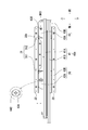
- FIG. 3 is a view showing the right side surface of the cooking cooker 1 according to the present embodiment. Specifically, FIG. 3 shows the right side surface of the cooker 1 with the housing 14 removed.
- FIG. 4 is a diagram showing a left side surface of the cooking cooker 1 according to the present embodiment. Specifically, FIG. 4 shows the left side surface of the cooker 1 with the housing 14 removed.
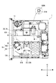
- FIG. 5 is a diagram showing the bottom surface of the cooking cooker 1 according to the present embodiment. Specifically, FIG. 5 shows the bottom surface of the cooker 1 with the housing 14 removed.
- the drawer body 130 has a lid portion 131, a mounting portion 132, a pair of left and right slide members 133, and a support member 20.
- the support member 20 is an example of an angle adjusting member.
- the lid 131 can open and close the first opening 11A (see FIG. 1) of the panel 11. As shown in FIG. 1, the lid portion 131 is a substantially rectangular plate-shaped member.
- the mounting unit 132 can mount an object to be heated. As shown in FIGS. 3 and 4, the lid 131 has a rear surface 131A.
- the mounting portion 132 is attached to the rear surface 131A of the lid portion 131.
- the rear surface 131A of the lid 131 is flat.
- the rear surface 131A of the lid portion 131 is an example of the second surface.
- the pair of left and right slide members 133 support the lid portion 131.
- the pair of left and right slide members 133 support the mounting portion 132 by supporting the lid portion 131.
- the pair of left and right slide members 133 are attached to the rear surface 131A of the lid portion 131.
- Each of the pair of left and right slide members 133 extends along the front-rear direction.
- Each of the pair of left and right slide members 133 is a tubular member.
- Each of the pair of left and right slide members 133 has a hollow portion inside.
- the pair of left and right slide members 133 has a right side slide member 133a (see FIG. 3) and a left side slide member 133b (see FIG. 4).
- the support member 20 supports the lid portion 131.
- the support member 20 supports the mounting portion 132 by supporting the lid portion 131.
- the support member 20 is attached to the rear surface 131A of the lid portion 131 at a substantially central portion in the left-right direction and below the mounting portion 132.
- the support member 20 is a plate-shaped member having a longitudinal direction in the front-rear direction.
- the support member 20 engages with the drive mechanism 15.
- the drive mechanism 15 will be described later with reference to FIGS. 1 to 12.
- FIG. 6 is a front view of the cooking cooker 1 according to the present embodiment. More specifically, FIG. 6 shows the cooker 1 in a state where the drawer body 130 is removed.
- the panel 11 is a rectangular plate-shaped member.
- the panel 11 has a pair of second openings 11B, a third opening 11C, and a front surface 11D in addition to the first opening 11A.
- the front surface 11D is flat.
- the front surface 11D is an example of the first surface.
- the pair of second openings 11B has a right side opening 11Ba and a left side opening 11Bb.
- the right opening 11Ba is located on the right side of the first opening 11A of the panel 11.
- the left opening 11Bb is located on the left side of the first opening 11A of the panel 11.
- the right slide member 133a described with reference to FIGS. 3 and 4 penetrates the right opening 11Ba of the panel 11.
- the left slide member 133b described with reference to FIGS. 3 and 4 penetrates the left opening 11Bb of the panel 11.
- the third opening 11C is located below the first opening 11A of the panel 11 and at a substantially central portion in the left-right direction.
- the support member 20 described with reference to FIGS. 3 and 4 penetrates the third opening 11C of the panel 11.
- the cooking chamber 10 has a pair of left and right mounting portions 30.
- the drawer unit 13 further includes a pair of left and right slide rails 40.
- the pair of left and right mounting portions 30 is an example of mounting portions.
- the pair of left and right slide rails 40 is an example of an angle adjusting member.
- a pair of left and right slide rails 40 are rotatably attached to the pair of left and right mounting portions 30.
- the pair of left and right mounting portions 30 have a right mounting portion 30a (see FIG. 3) and a left mounting portion 30b (see FIG. 4).
- the cooking chamber 10 has a right wall 10A.
- the right side mounting portion 30a is located on the right wall 10A of the cooking chamber 10.
- the cooking chamber 10 has a left wall 10B.
- the left side mounting portion 30b is located on the left wall 10B of the cooking chamber 10. Details of the configuration of the right side mounting portion 30a will be described later with reference to FIGS. 13 to 15.
- the configuration of the left side mounting portion 30b is substantially the same as the configuration of the right side mounting portion 30a.
- the description of the configuration of the left side mounting portion 30b is omitted.
- a pair of left and right slide members 133 are engaged with the pair of left and right slide rails 40.
- the pair of left and right slide rails 40 slidably support the drawer body 130 in the front-rear direction.
- the pair of left and right slide rails 40 have a right side slide rail 40a (see FIG. 3) and a left side slide rail 40b (see FIG. 4).
- Each of the right slide rail 40a and the left slide rail 40b is attached to the outer surface of the cooking chamber 10. Specifically, as shown in FIG. 3, the right side slide rail 40a is attached to the right side attachment portion 30a. The right side slide member 133a of the drawer body 130 is slidably supported by the right side slide rail 40a. As shown in FIG. 4, the left slide rail 40b is attached to the left attachment portion 30b. The left side slide member 133b of the drawer body 130 is slidably supported by the left side slide rail 40b.
- the configurations of the right slide rail 40a and the left slide rail 40b are substantially the same. Details of the configuration of the pair of left and right slide rails 40 will be described later with reference to FIGS. 13, 15 and 16.
- FIG. 7 is a cross-sectional view of the cooker 1 cut along the cutting line VII of FIG.
- FIG. 8 is a cross-sectional view of the cooker 1 cut along the cutting line VIII of FIG.
- the cooking chamber 10 has an upper wall 10C, a bottom wall 10D, and a rear wall 10E in addition to the right wall 10A and the left wall 10B.
- the accommodation space 1A is formed by a right wall 10A, a left wall 10B, an upper wall 10C, a bottom wall 10D, and a rear wall 10E.
- the accommodation space 1A of the cooking chamber 10 has a substantially rectangular parallelepiped shape.
- the cooking cooker 1 further includes a first blower section 51, a second blower section 52, a microwave supply section 53, and a grill section 54 (see FIG. 8).
- the first blower section 51 supplies the first hot air H1 into the accommodation space 1A. That is, the first blower unit 51 executes the first hot air circulation heating mode.
- the first blower portion 51 is attached to the outside of the rear wall 10E.
- the rear wall 10E has a plurality of first outlet holes 10E1 and a plurality of first suction holes 10E2.
- the plurality of first suction hole portions 10E2 are located at substantially the central portion of the rear wall 10E.
- the plurality of first outlet holes 10E1 are located on the outer portions of the plurality of first suction holes 10E2 of the rear wall 10E.
- the first blower section 51 includes a first blower chamber 510, a first heater 511, a first centrifugal fan 512, a first drive section 513, and a first energizing section 514.
- the first heater 511 and the first centrifugal fan 512 are housed in the first blower chamber 510.
- the first drive unit 513 and the first energization unit 514 are located outside the first blower chamber 510.
- the first energizing unit 514 energizes the first heater 511.
- the energized first heater 511 heats the air in the first blower chamber 510.
- the first drive unit 513 drives the first centrifugal fan 512.
- the driven first centrifugal fan 512 blows the air in the first blower chamber 510 into the accommodation space 1A through the plurality of first blowout holes 10E1. Further, the driven first centrifugal fan 512 sucks the air in the accommodation space 1A into the first air blowing chamber 510 through the plurality of first suction holes 10E2.
- the plurality of first suction hole portions 10E2 face the first centrifugal fan 512 in the axial direction of the first centrifugal fan 512.
- the first heater 511 is, for example, a sheathed heater.
- the first drive unit 513 is, for example, a motor.
- the second blower 52 supplies the second hot air H2 into the accommodation space 1A. That is, the second blower unit 52 executes the second hot air circulation heating mode.
- the second blower 52 is attached to the outside of the upper wall 10C.
- the upper wall 10C has a plurality of second outlet holes 10C1 and a plurality of second suction holes 10C2.
- the plurality of second outlet holes 10C1 and the plurality of second suction holes 10C2 are located substantially at the center of the upper wall 10C.
- the second blower unit 52 has a second blower chamber 520, a second heater 521, a second centrifugal fan 522, a second drive unit 523, and a second energizing unit 524.
- the second heater 521 and the second centrifugal fan 522 are housed in the second blower chamber 520.
- the second drive unit 523 and the second energization unit 524 are located outside the second blower chamber 520.
- the second energizing unit 524 energizes the second heater 521.
- the energized second heater 521 heats the air in the second blower chamber 520.
- the second drive unit 523 drives the second centrifugal fan 522.
- the driven second centrifugal fan 522 blows the air in the second blower chamber 520 into the accommodation space 1A through the plurality of second outlet holes 10C1. Further, the driven second centrifugal fan 522 sucks the air in the accommodation space 1A into the second blower chamber 520 through the plurality of second suction holes 10C2.
- the plurality of second suction hole portions 10C2 face the second centrifugal fan 522 in the axial direction of the second centrifugal fan 522.
- the second heater 521 is, for example, a sheathed heater.
- the second drive unit 523 is, for example, a motor.
- the microwave supply unit 53 supplies microwaves into the accommodation space 1A. That is, the microwave supply unit 53 executes the range heating mode.
- the microwave supply unit 53 is attached to the bottom wall 10D side.
- the microwave supply unit 53 includes a magnetron 531, a rotating antenna 532, a waveguide 533, and an antenna motor 534.
- the bottom wall 10D has a recess 10D1.
- the recess 10D1 is located at a substantially central portion of the bottom wall 10D.
- the cooking chamber 10 has an oven tray 530.
- the oven tray 530 is attached to the bottom wall 10D.
- the oven tray 530 is a plate-shaped member.
- the oven tray 530 covers the recess 10D1.
- the oven tray 530 forms a space 10D2 with the recess 10D1.
- the rotating antenna 532 is located in the space 10D2.
- the magnetron 531, the waveguide 533, and the antenna motor 534 are located outside the recess 10D1.
- the magnetron 531 generates microwaves.
- the recess 10D1 has a feeding hole portion 10D3.
- the waveguide 533 propagates the generated microwave to the feeding hole portion 10D3.
- the antenna motor 534 drives the rotating antenna 532.
- the rotating antenna 532 agitates the microwave and radiates the microwave into the accommodation space 1A.
- the material of the oven tray 530 includes ceramics or glass. Since the material of the oven tray 530 includes ceramics or glass, the oven tray 530 can easily transmit microwaves. Therefore, when the microwave oven heating mode is executed, the heating cooker 1 can efficiently cook the object to be heated even if the microwave is supplied from the recess 10D1 side.
- the grill portion 54 supplies heat into the accommodation space 1A.
- the grill unit 54 executes the grill heating mode.
- the grill portion 54 has a heater portion 541 for cooking and a third energizing portion 542.
- the heater unit 541 for cooking is located at the upper part in the accommodation space 1A.
- the third energizing unit 542 is located outside the left wall 10B.
- the third energizing unit 542 projects from the outer surface of the left wall 10B of the cooking chamber 10.
- the third energizing unit 542 energizes the heating cooking heater unit 541.
- the energized heating / cooking heater unit 541 generates heat and radiates heat.
- the heater unit 541 for cooking is, for example, a U-shaped sheathed heater.
- FIG. 9 is a block diagram showing the configuration of the cooking cooker 1 according to the present embodiment.
- the cooking cooker 1 further includes a control unit 55 and a storage unit 56.
- the control unit 55 is a hardware circuit.
- the hardware circuit includes a processor such as a CPU (Central Processing Unit).
- the control unit 55 executes the operation panel unit 12, the first drive unit 513, the first energization unit 514, the second drive unit 523, the second energization unit 524, and the second. 3 Controls the energizing unit 542, the microwave supply unit 53, and the storage unit 56.
- the storage unit 56 is composed of a RAM (Random Access Memory) and a ROM (Read Only Memory).
- the storage unit 56 stores a control program for controlling the operation of each part of the cooking cooker 1.
- the storage unit 56 stores the setting information input by operating the operation panel unit 12.
- FIG. 10 is a partial cross-sectional view of the cooker 1 cut along the cutting line X of FIG.
- FIG. 11 is a perspective view showing the appearance of the cooking cooker 1 according to the present embodiment. More specifically, FIG. 11 shows the appearance of the cooker 1 in a state in which the drawer body 130 is pulled out, as viewed from above diagonally to the right.
- FIG. 12 is a perspective view showing the appearance of the support member 20 according to the present embodiment. Specifically, FIG. 12 shows the appearance of the support member 20 as viewed from below diagonally to the left.
- the cooking chamber 10 further includes a guide rail portion 101.
- the guide rail portion 101 guides the support member 20 in the drawer direction of the drawer body 130.
- the guide rail portion 101 is located at the lower part of the cooking chamber 10.
- the guide rail portion 101 extends along the front-rear direction.
- the drawer body 130 further includes an engaging portion 134.
- the engaging portion 134 engages with the guide rail portion 101.
- the support member 20 has an upper surface 20A.
- the engaging portion 134 is rotatably attached to the upper surface 20A of the support member 20 by a tightening screw 61A (see FIG. 12) and a shaft screw 61B (see FIG. 12).
- the engaging portion 134 has a substantially U-shaped cross section. As shown in FIG. 5, the engaging portion 134 extends along the front-rear direction.
- the tightening screw 61A and the shaft screw 61B are hexagon bolts.
- the tightening screw 61A is an example of the second tightening member.
- the shaft screw 61B is an example of a second shaft member.
- the support member 20 can be used for adjusting the angle of the rear surface 131A (see FIG. 11) of the drawer 130 with respect to the front surface 11D (see FIG. 6) of the cooking chamber 10.
- the angle of the rear surface 131A (see FIG. 11) of the drawer body 130 with respect to the front surface 11D (see FIG. 6) of the cooking chamber 10 is referred to as a “sealing angle”.
- the sealing angle is approximately 0 degrees
- the accommodation space 1A of the cooking chamber 10 is sealed by the lid 131 of the drawer 130. Therefore, the heating cooker 1 can prevent radio wave leakage from the heating cooking chamber 10 when the microwave supply unit 53 is being driven.
- the support member 20 has a base plate portion 21 and a rack portion 22.
- the base plate portion 21 and the rack portion 22 are integrated.
- the base plate portion 21 is a plate-like object having a longitudinal direction in the front-rear direction.
- the engaging portion 134 described with reference to FIGS. 5 and 10 has a front fixing hole.
- the front fixing hole of the engaging portion 134 is a screw hole to which the shaft screw 61B (see FIG. 12) is fixed.
- the front fixing hole of the engaging portion 134 is located at the front portion of the engaging portion 134.
- the base plate portion 21 has a shaft support hole portion H20B facing the front fixing hole of the engaging portion 134.
- the shaft support hole portion H20B is a through hole for the support member 20 to be rotatably supported by the engaging portion 134.
- the shaft screw 61B is fixed to the front fixing hole of the engaging portion 134 via the shaft support hole portion H20B of the support member 20.
- the support member 20 is rotatable with respect to the engaging portion 134 about the shaft screw 61B.
- the engaging portion 134 is engaged with the guide rail portion 101 (see FIG. 10) and is fixed to the guide rail portion 101.
- the shaft support hole portion H20B of the support member 20 is an example of the shaft support portion.
- the engaging portion 134 described with reference to FIGS. 5 and 10 has a rear mounting hole.
- the rear mounting hole of the engaging portion 134 is a screw hole to which the tightening screw 61A (see FIG. 12) is fixed.
- the rear mounting hole of the engaging portion 134 is located at the rear portion of the engaging portion 134.
- the base plate portion 21 has left and right regulation hole portions H20A facing the rear mounting holes of the engaging portion 134.
- the left-right regulation hole portion H20A is a screw hole for restricting the rotation direction of the support member 20 in the substantially left-right direction.
- the left and right regulation hole portion H20A is an elongated hole whose longitudinal direction is substantially left and right.
- the rear mounting hole of the engaging portion 134 is an example of the second fixing portion.
- the left / right regulation hole portion H20A of the support member 20 is an example of the left / right regulation portion.
- the tightening screw 61A tightens the support member 20. Specifically, when the tightening screw 61A is screwed into the rear fixing hole of the engaging portion 134 and fixed to the rear fixing hole of the engaging portion 134, the support member 20 is tightened.
- the tightening screw 61A regulates the rotation direction of the support member 20.
- the rotation direction of the support member 20 is restricted to substantially the left-right direction along the shape of the elongated hole of the left-right regulation hole portion H20A of the support member 20.
- the state in which the support member 20 is rotatable with respect to the engaging portion 134 is referred to as the “rotating state” of the tightening screw 61A.
- the state in which the arrangement of the support member 20 with respect to the engaging portion 134 is fixed is referred to as a “tightening state” of the tightening screw 61A.
- the rack portion 22 is a substantially rectangular parallelepiped having a longitudinal direction in the front-rear direction. As shown in FIG. 10, the rack portion 22 is attached to the left end portion of the upper surface 20A of the base plate portion 21. As shown in FIG. 12, the rack portion 22 has a plurality of teeth 22A along the front-rear direction.
- the cooking cooker 1 has a drive mechanism 15.
- the cooking cooker 1 has an arrangement space between the outer surface of the bottom wall 10D of the cooking chamber 10 and the inner surface of the bottom wall 14D of the housing 14.
- the drive mechanism 15 is located in the arrangement space.
- the drive mechanism 15 includes a drive mechanism drive motor 151 and a pinion 152.
- the control unit 55 described with reference to FIG. 9 controls the drive mechanism drive motor 151.
- the control unit 55 controls the drive motor 151 for the drive mechanism to generate a driving force that rotates the pinion 152 in the forward or reverse rotation.
- the pinion 152 meshes with the rack portion 22 of the support member 20.
- the drive mechanism 15 brings the drawer body 130 into an open state or a closed state by rotating the pinion 152 in the forward direction or the reverse direction.
- the open state of the drawer body 130 means a state in which the mounting portion 132 of the drawer body 130 is pulled out from the arrangement space.
- the closed state of the drawer body 130 means a state in which the mounting portion 132 of the drawer body 130 is pulled into the arrangement space, and the front surface 11D of the cooking chamber 10 and the rear surface 131A of the drawer body 130 are in contact with each other.
- FIG. 13 is a partial cross-sectional view of the cooker 1 cut along the cutting line XIII of FIG. Specifically, FIG. 13 shows a cross section of the right wall 10A, the right side mounting portion 30a, the right side slide rail 40a, and the right side slide member 133a.
- FIG. 14 is a perspective view of the right side mounting portion 30a according to the present embodiment. More specifically, FIG. 14 shows the right side mounting portion 30a as viewed from above diagonally rear right.
- the right side mounting portion 30a has a main body portion 31, a first flange portion 32, and a second flange portion 33.
- the main body portion 31, the first flange portion 32, and the second flange portion 33 are integrated.
- the left portion of the main body portion 31, the first flange portion 32, and the second flange portion 33 are embedded in the right wall 10A.
- the first flange portion 32 extends upward from the left edge portion of the upper portion of the main body portion 31.
- the first flange portion 32 is attached to the right wall 10A. As shown in FIG. 14, the first flange portion 32 is formed along the front-rear direction of the main body portion 31.
- the second flange portion 33 extends downward from the left edge portion of the lower portion of the main body portion 31.
- the second flange portion 33 is attached to the right wall 10A.
- the second flange portion 33 is formed along the front-rear direction of the main body portion 31.
- the main body portion 31 has a rear side fixing portion 311 and a front side fixing portion 312.
- the rear fixing portion 311 is located at the rear portion of the main body portion 31 in the front-rear direction.
- the front fixing portion 312 is located at the front portion of the main body portion 31 in the front-rear direction.
- the rear fixing portion 311 and the front fixing portion 312 are groove-shaped objects having a substantially U-shaped cross section and a longitudinal direction in the front-rear direction.
- the rear fixing portion 311 is a portion where the rear mounting support portion 42 of the right side slide rail 40a, which will be described later with reference to FIG. 15, is fixed (see FIG. 13).
- the rear fixing portion 311 has a rear facing wall 311A and a pair of rear standing walls 311B.
- One of the pair of rear facing walls 311B is erected from the upper edge of the rear facing wall 311A toward the left.
- the other of the pair of rear standing walls 311B is erected from the lower edge of the rear facing wall 311A toward the left.
- the rear facing wall 311A and the pair of rear standing walls 311B are integrated.
- the rear facing wall 311A faces the outer surface of the right wall 10A.
- the rear facing wall 311A is a flat plate.
- the rear facing wall 311A has a rear fixing hole H311.
- the rear fixing hole portion H311 is a screw hole into which the tightening screw 62A described with reference to FIG. 15 is fixed.
- the rear fixing hole portion H311 is located at the central portion in the front-rear direction of the rear facing wall 311A and at the upper portion.
- the rear fixing hole portion H311 is an example of the first fixing portion.
- the tightening screw 62A is an example of the first tightening member.
- the front side fixing portion 312 is a portion where the front side mounting support portion 43 of the right side slide rail 40a, which will be described later with reference to FIG. 15, is fixed.
- the front fixed portion 312 has a front facing wall 312A and a pair of front standing walls 312B.
- One of the pair of front standing walls 312B is erected from the upper edge of the front facing wall 312A toward the left.
- the other of the pair of front standing walls 312B is erected from the lower edge of the front facing wall 312A toward the left.
- the front facing wall 312A and the pair of front standing walls 312B are integrated.
- the front facing wall 312A faces the outer surface of the right wall 10A.
- the front facing wall 312A is a flat plate.
- the front facing wall 312A has a front fixing hole H312.
- the front fixing hole portion H312 is a screw hole into which a shaft screw 62B, which will be described later, is screwed with reference to FIG.
- the front fixing hole H312 is located at the center of the front facing wall 312A in the front-rear direction and at the upper part.
- the shaft screw 62B is an example of the first shaft member.
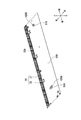
- FIG. 15 is a front view of the right side mounting portion 30a to which the right side slide rail 40a according to the present embodiment is mounted. Specifically, FIG. 15 shows the right side mounting portion 30a to which the right side slide rail 40a is mounted, as viewed from the right.
- FIG. 16 is a front view of the left side mounting portion 30b to which the left side slide rail 40b according to the present embodiment is mounted. Specifically, FIG. 16 shows a left side mounting portion 30b to which the left side slide rail 40b is mounted, as viewed from the left.
- the pair of left and right slide rails 40 can be used to adjust the sealing angle.
- the right side slide rail 40a has a rail portion 41, a rear mounting support portion 42, and a front mounting support portion 43.
- the rail portion 41, the rear mounting support portion 42, and the front mounting support portion 43 are integrated.
- the rail portion 41 engages with the right side slide member 133a described with reference to FIG.
- the rail portion 41 slidably supports the right side slide member 133a.
- the rail portion 41 has an upper rail portion 41A and a lower rail portion 41B.
- the upper rail portion 41A and the lower rail portion 41B are provided side by side along the vertical direction.
- the upper rail portion 41A and the lower rail portion 41B are rail-shaped objects having a longitudinal direction in the front-rear direction. In the present embodiment, the length of the upper rail portion 41A is shorter than the length of the lower rail portion 41B in the front-rear direction.
- the rear mounting support portion 42 supports the rail portion 41 and is mounted on the rear fixing portion 311 of the right side mounting portion 30a.
- the rear mounting support portion 42 is a bracket having a substantially L-shaped cross section.
- the rear mounting support portion 42 has a rear base plate portion 42A and a rear support plate portion 42B.
- the rear support plate portion 42B extends from the lower edge portion of the rear base plate portion 42A toward the right.
- the rear base plate portion 42A and the rear support plate portion 42B are integrated.
- the rear base plate portion 42A is a flat plate.
- the rear base plate portion 42A has a vertical regulation hole portion H42 of the right slide rail 40a.
- the vertical regulation hole H42 of the right slide rail 40a is a screw hole for restricting the rotation direction of the right slide rail 40a in the vertical direction.
- a tightening screw 62A is inserted into the vertical regulation hole H42 of the right slide rail 40a.
- the vertical regulation hole H42 of the right slide rail 40a faces the rear fixing hole H311 (see FIG. 14) of the right mounting portion 30a.
- the vertical regulation hole portion H42 of the right slide rail 40a is an elongated hole whose longitudinal direction is the vertical direction.
- the vertical regulation hole portion H42 of the right slide rail 40a is an example of the vertical regulation portion.
- the right side slide rail 40a is rotatable about the shaft screw 62B with respect to the right side mounting portion 30a.
- the tightening screw 62A tightens the right slide rail 40a. Specifically, the tightening screw 62A is screwed into the rear fixing hole H311 (see FIG. 14) of the right side mounting portion 30a and fixed to the rear fixing hole H311 (see FIG. 14) of the right side mounting portion 30a. And tighten the right slide rail 40a.
- the tightening screw 62A regulates the rotation direction of the right slide rail 40a. Specifically, the tightening screw 62A regulates the rotation direction of the right slide rail 40a substantially in the vertical direction along the shape of the elongated hole of the vertical regulation hole portion H42 of the right slide rail 40a by being loosened.
- the tightening screw 62A is a machine screw.
- the state in which the right side slide rail 40a is rotatable with respect to the right side mounting portion 30a is referred to as a “rotating state” of the tightening screw 62A.
- the state in which the arrangement of the right side slide rail 40a with respect to the right side mounting portion 30a is fixed is referred to as a “tightening state” of the tightening screw 62A.
- the rear support plate portion 42B is a flat plate. As shown in FIG. 13, the rail portion 41 is mounted on the rear support plate portion 42B. The rail portion 41 is fixed to the rear support plate portion 42B.
- the front mounting support portion 43 supports the rail portion 41 and is mounted on the front fixing portion 312 (see FIG. 14) of the right mounting portion 30a.
- the front mounting support portion 43 is a bracket having a substantially L-shaped cross section, similarly to the rear mounting support portion 42.
- the front mounting support portion 43 has a front base plate portion 43A and a front support plate portion 43B.
- the front base plate portion 43A extends from the lower edge portion of the front base plate portion 43A toward the right.
- the front base plate portion 43A and the front support plate portion 43B are integrated.
- the front base plate portion 43A is a flat plate.
- the front base plate portion 43A has a shaft support hole portion H43.
- the shaft support hole portion H43 of the right slide rail 40a is a through hole for rotatably supporting the right slide rail 40a by the right mounting portion 30a.
- a shaft screw 62B is inserted into the shaft support hole H43 of the right slide rail 40a.
- the shaft support hole portion H43 of the right slide rail 40a faces the front side fixing hole portion H312 (see FIG. 14) of the right side mounting portion 30a.
- the shaft screw 62B is screwed to the front fixing hole portion H312 of the right side mounting portion 30a via the shaft support hole portion H43 of the right side slide rail 40a, so that the right side slide rail 40a is on the right side with the shaft screw 62B as the center. It is rotatable with respect to the mounting portion 30a.
- the shaft screw 62B is a machine screw.
- the shaft support hole portion H43 of the right slide rail 40a is an example of the shaft support portion.
- the front support plate portion 43B is a flat plate.
- the rail portion 41 is mounted on the front support plate portion 43B.
- the rail portion 41 is fixed to the front support plate portion 43B.
- the configuration of the left side mounting portion 30b is substantially the same as the configuration of the right side mounting portion 30a.
- the configuration of the left slide rail 40b is substantially the same as the configuration of the right slide rail 40a.
- the shaft support hole portion H43 of the left slide rail 40b is a through hole for the left slide rail 40b to be rotatably supported by the left mounting portion 30b.
- a shaft screw 63B is inserted through the shaft support hole H43 of the left slide rail 40b.
- the shaft screw 63B is screwed to the front fixing hole portion H312 of the left side mounting portion 30b via the shaft support hole portion H43 of the left side slide rail 40b, so that the left side slide rail 40b is centered on the shaft screw 63B on the left side. It is rotatable with respect to the mounting portion 30b.
- the shaft screw 63B is a machine screw.
- the shaft support hole portion H43 of the left slide rail 40b is an example of the shaft support portion.
- the vertical regulation hole H42 of the left slide rail 40b is a through hole for restricting the rotation direction of the left slide rail 40b in the vertical direction.
- a tightening screw 63A is inserted into the vertical regulation hole H42 of the left slide rail 40b.
- the vertical regulation hole H42 of the left slide rail 40b is an example of the vertical regulation.
- the tightening screw 63A tightens the left slide rail 40b. Specifically, when the tightening screw 63A is screwed into the rear fixing hole H311 of the left side mounting portion 30b and fixed to the rear fixing hole H311 of the left side mounting portion 30b, the left slide rail 40b is tightened.
- the tightening screw 63A regulates the rotation direction of the left slide rail 40b. Specifically, the tightening screw 63A regulates the rotation direction of the left slide rail 40b substantially in the vertical direction along the shape of the elongated hole of the vertical regulation hole portion H42 of the left slide rail 40b by being loosened.
- the tightening screw 63A is a machine screw.
- the state in which the left side slide rail 40b is rotatable with respect to the left side mounting portion 30b is referred to as a “rotating state” of the tightening screw 63A.
- the state in which the arrangement of the left slide rail 40b with respect to the left side mounting portion 30b is fixed is referred to as a “tightening state” of the tightening screw 63A.
- the sealing angle is approximately 0 degrees in order to prevent electromagnetic leakage.
- the arrangement of the drawer 130 with respect to the cooking chamber 10 is efficiently adjusted so that the sealing angle is approximately 0 degrees.
- the sealing angle is maintained at substantially 0 degrees. In this way, in the present embodiment, the arrangement of the drawer body 130 for preventing radio wave leakage can be easily adjusted.
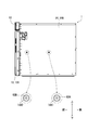
- FIG. 17 is a view showing the right side surface of the cooking cooker 1 according to the present embodiment. Specifically, FIG. 17 shows the outer surface of the right wall 14A of the housing 14.
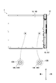
- FIG. 18 is a diagram showing a left side surface of the cooking cooker 1 according to the present embodiment. Specifically, FIG. 18 shows the outer surface of the left wall 14B of the housing 14.
- FIG. 19 is a diagram showing the bottom surface of the cooking cooker 1 according to the present embodiment. Specifically, FIG. 19 shows the outer surface of the bottom wall 14D of the housing 14.
- the right wall 14A of the housing 14 has a first through hole 14A1 and a second through hole 14A2.
- the first through hole 14A1 faces the rear fixing hole portion H311 of the right side mounting portion 30a in the left-right direction.
- the tightening screw 62A (see FIG. 15) is screwed into the rear fixing hole H311 of the right side mounting portion 30a. Therefore, the first through hole 14A1 faces the tightening screw 62A. Therefore, for example, the user can easily adjust the tightening condition of the right slide rail 40a by the tightening screw 62A through the first through hole 14A1 by using a tool without removing the housing 14. can.
- the tool includes, for example, a screwdriver.
- the housing 14 may include a first cover member that closes the first through hole 14A1.
- the first cover member can open the first through hole 14A1 when adjusting the tightening condition of the tightening screw 62A.
- the second through hole 14A2 faces the front side fixing hole portion H312 of the right side mounting portion 30a in the left-right direction.
- the shaft screw 62B (see FIG. 15) is screwed into the front fixing hole H312 of the right side mounting portion 30a. Therefore, the second through hole 14A2 faces the shaft screw 62B. Therefore, for example, the user can easily adjust the tightening condition of the right side slide rail 40a by the shaft screw 62B through the second through hole 14A2 by using a tool without removing the housing 14. ..
- the housing 14 may include a second cover member that closes the second through hole 14A2.
- the second cover member can open the second through hole 14A2 when adjusting the tightening condition of the shaft screw 62B.
- the left wall 14B of the housing 14 has a third through hole 14B1 and a fourth through hole 14B2.
- the third through hole 14B1 faces the rear fixing hole portion H311 of the left side mounting portion 30b in the left-right direction.
- the tightening screw 63A (see FIG. 16) is screwed into the rear fixing hole portion H311 of the left side mounting portion 30b. Therefore, the first through hole 14A1 faces the tightening screw 63A. Therefore, for example, the user can easily adjust the tightening condition of the left slide rail 40b by the tightening screw 63A through the third through hole 14B1 without removing the housing 14 by using a tool. can.
- the housing 14 may include a third cover member that closes the third through hole 14B1.
- the third cover member can open the third through hole 14B1 when adjusting the tightening condition of the tightening screw 63A.
- the fourth through hole 14B2 faces the front fixing hole portion H312 of the left side mounting portion 30b in the left-right direction.
- the shaft screw 63B (see FIG. 16) is screwed into the front fixing hole portion H312 of the left side mounting portion 30b. Therefore, the fourth through hole 14B2 faces the shaft screw 63B. Therefore, for example, the user can easily adjust the tightening condition of the left slide rail 40b by the shaft screw 63B through the fourth through hole 14B2 by using a tool without removing the housing 14. ..
- the housing 14 may include a fourth cover member that closes the fourth through hole 14B2.
- the fourth cover member can open the fourth through hole 14B2 when adjusting the tightening condition of the shaft screw 63B.
- the bottom wall 14D of the housing 14 has a fifth through hole 14D1 and a sixth through hole 14D2.
- the rear fixing hole portion of the engaging portion 134 described with reference to FIGS. 5, 10 and 11 moves in the drawing direction of the drawer body 130 together with the support member 20.
- the fifth through hole 14D1 faces the rear fixing hole portion of the engaging portion 134 in the vertical direction when the drawer body 130 is in the closed state.
- the tightening screw 61A (see FIG. 5) is screwed into the rear fixing hole portion of the engaging portion 134. Therefore, the fifth through hole 14D1 faces the tightening screw 61A. Therefore, for example, the user can easily adjust the tightening condition of the support member 20 by the tightening screw 61A through the fifth through hole 14D1 by using a tool without removing the housing 14. ..
- the housing 14 may include a fifth cover member that closes the fifth through hole 14D1.
- the fifth cover member can open the fifth through hole 14D1 when adjusting the tightening condition of the tightening screw 61A.
- the sixth through hole 14D2 faces the front fixing hole portion of the engaging portion 134 in the vertical direction when the drawer body 130 is in the closed state.
- the shaft screw 61B (see FIG. 5) is screwed into the front fixing hole portion of the engaging portion 134. Therefore, the sixth through hole 14D2 faces the shaft screw 61B. Therefore, for example, the user can easily adjust the tightening condition of the support member 20 by the shaft screw 61B through the sixth through hole 14D2 by using a tool without removing the housing 14.
- the housing 14 may include a sixth cover member that closes the sixth through hole 14D2.
- the sixth cover member can open the sixth through hole 14D2 when adjusting the tightening condition of the shaft screw 61B.
- FIG. 20 is a diagram showing the appearance of the cabinet 2 in which the cooking cooker 1 according to the present embodiment is built-in.
- the cooking cooker 1 is built in and arranged in the cabinet 2. As shown in FIG. 20, the cabinet 2 has a storage space DR. A cooking device 1 is arranged in the accommodation space DR.
- the accommodation space DR is a rectangular parallelepiped space.
- the cabinet 2 has a right inner surface 2A, a left inner surface 2B, an upper inner surface 2C, a lower inner surface 2D, and a rear inner surface 2E.
- the accommodation space DR is formed by a right inner surface 2A, a left inner surface 2B, an upper inner surface 2C, a lower inner surface 2D, and a rear inner surface 2E.
- the cooking cooker 1 includes a cooking room 10, a housing 14, a microwave supply unit 53, and a drawer unit 13.
- the drawer unit 13 includes a drawer 130, a support member 20, and a pair of left and right slide rails 40.
- the housing 14 has a first through hole 14A1, a third through hole 14B1, and a fifth through hole 14D1.
- the sealing angle is approximately 0 degrees.
- the user can use the tightening screw 61A and the tightening screw through the first through hole 14A1, the third through hole 14B1 and the fifth through hole 14D1 of the housing 14 without removing the housing 14. You can access 62A and the tightening screw 63A.
- the user can adjust the arrangement of the pair of slide rails 40 and the support member 20 by using the first through hole 14A1, the third through hole 14B1 and the fifth through hole 14D1 of the housing 14.
- the user can adjust the arrangement of the drawer body 130 so that the sealing angle is substantially 0 degrees.
- the productivity of the cooker 1 is improved.
- the support member 20 includes a shaft support hole portion H20B and a left and right regulation hole portion H20A.
- the support member 20 can rotate around the shaft screw 61B along the left and right regulation hole portions H20A. Therefore, the user can rotate the support member 20 with respect to the cooking chamber 10 to make the sealing angle substantially 0 degrees.
- each of the pair of left and right slide rails 40 includes a shaft support hole portion H43 and a vertical regulation hole portion H42.
- the shaft screw 62B is inserted into the shaft support hole portion H43 of the right slide rail 40a
- the right slide rail 40a rotates about the shaft screw 62B along the vertical regulation hole portion H42 of the right slide rail 40a.
- the shaft screw 63B is inserted into the shaft support hole portion H43 of the left slide rail 40b
- the left slide rail 40b can rotate about the shaft screw 63B along the vertical regulation hole portion H42 of the left slide rail 40b. Is. Therefore, the user can rotate the pair of left and right slide rails 40 with respect to the cooking chamber 10 to make the sealing angle substantially 0 degrees.
- each of the pair of left and right slide rails 40 includes the upper and lower regulation holes H42.
- the right slide rail 40a can rotate substantially in the vertical direction around the shaft screw 62B when the shaft screw 62B is inserted into the shaft support hole portion H43 of the right slide rail 40a.
- the left slide rail 40b can rotate substantially in the vertical direction around the shaft screw 63B when the shaft screw 63B is inserted into the shaft support hole portion H43 of the left slide rail 40b. Therefore, the user can adjust the arrangement of the drawer body 130 in the vertical direction.
- the drawer body 130 includes a pair of left and right slide members 133.
- the heating cooking chamber 10 includes a pair of left and right mounting portions 30.
- Each of the right side mounting portion 30a and the left side mounting portion 30b includes a rear side fixing hole portion H311.
- the tightening screw 62A is fixed to the rear fixing hole H311 of the right side mounting portion 30a via the upper and lower regulation hole H42.
- the tightening screw 62A tightens the right slide rail 40a by being fixed to the rear fixing hole H311 of the right side mounting portion 30a.
- the first through hole 14A1 faces the rear fixing hole portion H311 of the right side mounting portion 30a.
- the tightening screw 63A is fixed to the rear fixing hole H311 of the left side mounting portion 30b via the upper and lower regulation hole H42.
- the tightening screw 63A tightens the left slide rail 40b by being fixed to the rear fixing hole H311 of the left side mounting portion 30b.
- the third through hole 14B1 faces the rear fixing hole portion H311 of the left side mounting portion 30b.
- the support member 20 includes the left and right regulation holes H20A.
- the support member 20 can rotate substantially in the left-right direction around the shaft screw 61B when the shaft screw 61B is inserted into the shaft support hole portion H20B. Therefore, the user can adjust the arrangement of the drawer body 130 in the left-right direction.
- the heating cooking chamber 10 includes a guide rail portion 101 (see FIG. 10).
- the drawer body 130 includes a lid portion 131 and an engaging portion 134.
- the engaging portion 134 includes a rear fixing portion.
- the tightening screw 61A is fixed to the rear fixing portion of the engaging portion 134 via the left and right regulating hole portions H20A.
- the tightening screw 61A tightens the support member 20 by being fixed to the rear fixing portion of the engaging portion 134.
- the fifth through hole 14D1 faces the rear fixing portion of the engaging portion 134 in a state where the front surface 11D of the cooking chamber 10 and the rear surface 131A of the drawer body 130 are in contact with each other.
- the support member 20 rotates in the left-right direction with respect to the engaging portion 134. ..
- the sealing angle approaches approximately 0 degrees.
- the cooking cooker 1 includes a first blower section 51 and a second blower section 52.
- the heating cooker 1 can cook the object to be heated by using hot air having different heating conditions.
- FIGS. 1 to 20 The embodiments of the present invention have been described above with reference to the drawings (FIGS. 1 to 20).
- the present invention is not limited to the above-described embodiment, and can be implemented in various aspects without departing from the gist of the present invention (for example, (1) to (8) shown below).
- the drawings are schematically shown mainly for each component for easy understanding, and the thickness, length, number, etc. of each component shown are different from the actual ones for the convenience of drawing creation. ..
- the material, shape, dimensions, etc. of each component shown in the above embodiment are merely examples, and are not particularly limited, and various changes can be made without substantially deviating from the effects of the present invention. be.
- the housing 14 has a second through hole 14A2, a fourth through hole 14B2, and a sixth through hole 14D2. Is not limited to this.
- the housing in the present invention does not have to have the second through hole 14A2, the fourth through hole 14B2, and the sixth through hole 14D2.
- the shaft support portion As described with reference to FIGS. 1 to 20, in the present embodiment, as the shaft support portion, the shaft support hole portion H20B of the support member 20 and the shaft support hole portion H43 of the pair of slide rails 40 are provided.
- the regulating portion As the regulating portion, the left and right regulating hole portions H20A of the support member 20 and the vertical regulating hole portion H42 of the pair of slide rails 40 are provided, but the present invention is not limited thereto.
- the angle adjusting member in the present invention does not have to have a shaft support portion and a regulating portion as long as the drawer unit 13 can be rotated with respect to the cooking chamber 10.
- the angle adjusting member in the present invention may have a hinge connected to the outer surface of the cooking chamber 10.
- each shape of the regulating portion in the present invention may be a plurality of recesses that can be engaged with the outer surface of the cooking chamber 10.
- the shaft support hole portion H20B of the support member 20 faces the front fixing hole of the engaging portion 134, and the support member 20 is restricted to the left and right.
- the hole H20A faces the rear fixing hole of the engaging portion 134, but the present invention is not limited thereto.
- the shaft support hole portion H20B of the support member 20 may face the rear side fixing hole of the engaging portion 134, and the left and right regulation hole portions H20A of the support member 20 may face the front side fixing hole of the engaging portion 134.
- the vertical regulation hole portion H42 of the right side slide rail 40a faces the rear side fixing hole portion H311 of the right side mounting portion 30a, and is on the right side.
- the shaft support hole portion H43 of the slide rail 40a faces the front side fixing hole portion H312 of the right side mounting portion 30a, but the present invention is not limited thereto.
- the vertical regulation hole portion H42 of the right slide rail 40a faces the front side fixing hole portion H312 of the right side mounting portion 30a
- the shaft support hole portion H43 of the right side slide rail 40a is the rear side fixing hole portion of the right side mounting portion 30a. It may face H311.
- the vertical regulation hole portion H42 of the left side slide rail 40b faces the rear side fixing hole portion H311 of the left side mounting portion 30b, and is on the left side.
- the shaft support hole portion H43 of the slide rail 40b faces the front side fixing hole portion H312 of the left side mounting portion 30b, but the present invention is not limited thereto.
- the vertical regulation hole portion H42 of the left slide rail 40b faces the front side fixing hole portion H312 of the left side mounting portion 30b
- the shaft support hole portion H43 of the left side slide rail 40b is the rear side fixing hole portion of the left side mounting portion 30b. It may face H311.
- the heating cooking chamber 10 includes a pair of left and right mounting portions 30, but the present invention is not limited thereto.
- the cooking cooker 1 does not have to include a pair of left and right mounting portions 30.
- the pair of left and right slide rails 40 may be mounted directly on the outer surface of the cooking chamber 10.
- the cooking cooker 1 includes a first blower section 51, a second blower section 52, and a grill section 54. Not limited to this.
- the cooking cooker of the present invention does not have to include the first blower section 51, the second blower section 52, and the grill section 54.
- the cooking cooker of the present invention may include one or two of the first blower section 51, the second blower section 52, and the grill section 54.
- the present invention is useful, for example, in the field of cookers.
- Heating cooker 1A Storage space 10 Heating cooking room 11A 1st opening 11D Front 13 Drawer unit 130 Drawer 131A Rear 14 Housing 14A1 1st through hole 30 Mounting part 40 Left and right pair of slide rails 53 Microwave supply part
Landscapes
- Engineering & Computer Science (AREA)
- Chemical & Material Sciences (AREA)
- Combustion & Propulsion (AREA)
- Mechanical Engineering (AREA)
- General Engineering & Computer Science (AREA)
- Physics & Mathematics (AREA)
- Electromagnetism (AREA)
- Baking, Grill, Roasting (AREA)
- Electric Ovens (AREA)
- Drawers Of Furniture (AREA)
Abstract
Description
1A 収容空間
10 加熱調理室
11A 第1開口
11D 前面
13 引出し体ユニット
130 引出し体
131A 後面
14 筐体
14A1 第1貫通孔
30 取付部
40 左右一対のスライドレール
53 マイクロ波供給部 1
Claims (8)
- 被加熱物を収容する収容空間と、前記収容空間と連通する開口と、前記開口の外周に配置された第1面とを有する加熱調理室と、
前記加熱調理室を収容する筐体と、
前記加熱調理室内にマイクロ波を供給するマイクロ波供給部と、
引出し体ユニットと
を備え、
前記引出し体ユニットは、
前記第1面と対向する第2面を有し、前記加熱調理室に対して引出し自在である引出し体と、
前記第1面に対する前記第2面の角度を調整するための角度調整部材と
を有し、
前記筐体は、貫通孔を有し、
前記貫通孔は、前記角度調整部材に対向する、加熱調理器。 A cooking room having a storage space for accommodating an object to be heated, an opening communicating with the storage space, and a first surface arranged on the outer periphery of the opening.
A housing for accommodating the cooking chamber and
A microwave supply unit that supplies microwaves to the cooking chamber,
Equipped with a drawer unit,
The drawer unit is
A drawer body having a second surface facing the first surface and being drawable with respect to the cooking chamber.
It has an angle adjusting member for adjusting the angle of the second surface with respect to the first surface.
The housing has a through hole and
The through hole is a heating cooker facing the angle adjusting member. - 前記角度調整部材は、
前記加熱調理室に回動可能に支持されるための軸支部と、
前記角度調整部材の回動方向を規制するための規制部と
を有し、請求項1に記載の加熱調理器。 The angle adjusting member is
A shaft support for being rotatably supported by the cooking chamber,
The heating cooker according to claim 1, further comprising a regulating portion for regulating the rotation direction of the angle adjusting member. - 前記規制部は、前記角度調整部材の回動方向を略上下方向に規制するための上下規制部を含む、請求項2に記載の加熱調理器。 The heating cooker according to claim 2, wherein the regulation unit includes a vertical regulation unit for restricting the rotation direction of the angle adjusting member in a substantially vertical direction.
- 前記引出し体は、前記引出し体の引出し方向に沿って延在するスライド部材を有し、
前記角度調整部材は、前記スライド部材が係合し、前記引出し体を前記引出し方向にスライド自在に支持するスライドレールを含み、
前記加熱調理室は、前記スライドレールの前記軸支部に軸支される第1軸部材が固定される取付部を有し、
前記取付部は、第1締付部材が固定される第1固定部を有し、
前記第1締付部材は、前記スライドレールの前記上下規制部を介して前記第1固定部に固定され、
前記第1締付部材は、前記第1固定部に固定されることにより、前記スライドレールを締め付け、
前記貫通孔は、前記第1固定部に対向する第1貫通孔を含む、請求項3に記載の加熱調理器。 The drawer has a slide member extending along the drawer direction of the drawer.
The angle adjusting member includes a slide rail to which the slide member engages and slidably supports the drawer body in the drawer direction.
The heating cooking chamber has a mounting portion to which a first shaft member pivotally supported by the shaft support portion of the slide rail is fixed.
The mounting portion has a first fixing portion to which the first tightening member is fixed.
The first tightening member is fixed to the first fixing portion via the vertical regulating portion of the slide rail.
The first tightening member tightens the slide rail by being fixed to the first fixing portion.
The heating cooker according to claim 3, wherein the through hole includes a first through hole facing the first fixing portion. - 前記規制部は、前記角度調整部材の回動方向を略左右方向に規制する左右規制部を含む、請求項2~請求項4のいずれか1項に記載の加熱調理器。 The heating cooker according to any one of claims 2 to 4, wherein the regulation unit includes a left-right regulation unit that regulates the rotation direction of the angle adjusting member substantially in the left-right direction.
- 前記加熱調理室は、前記引出し体の引出し方向に沿って延在する案内レール部を有し、
前記引出し体は、
前記第2面を有する蓋部と、
前記案内レール部に係合する係合部と
を有し、
前記角度調整部材は、前記係合部に回動可能に取り付けられ、前記蓋部を支持する支持部材を含み、
前記係合部は、前記支持部材の前記軸支部に軸支される第2軸部材が固定され、
前記係合部は、第2締付部材が固定される第2固定部を有し、
前記第2締付部材は、前記支持部材の前記左右規制部を介して、前記第2固定部に固定され、
前記第2締付部材は、前記第2固定部に固定されることにより、前記支持部材を締め付け、
前記貫通孔は、前記第1面と前記第2面とが当接する際に前記第2固定部に対向する第2貫通孔を含む、請求項5に記載の加熱調理器。 The cooking chamber has a guide rail portion extending along the drawer direction of the drawer body.
The drawer body
The lid having the second surface and
It has an engaging portion that engages with the guide rail portion, and has an engaging portion.
The angle adjusting member includes a support member that is rotatably attached to the engaging portion and supports the lid portion.
A second shaft member pivotally supported by the shaft support portion of the support member is fixed to the engaging portion.
The engaging portion has a second fixing portion to which the second tightening member is fixed.
The second tightening member is fixed to the second fixing portion via the left and right regulating portions of the support member.
The second tightening member tightens the support member by being fixed to the second fixing portion.
The cooking cooker according to claim 5, wherein the through hole includes a second through hole that faces the second fixing portion when the first surface and the second surface come into contact with each other. - 前記加熱調理室の内部に熱風を供給する送風部を備える、請求項1~請求項6のいずれか1項に記載の加熱調理器。 The heating cooker according to any one of claims 1 to 6, further comprising a blower for supplying hot air to the inside of the cooking chamber.
- 前記送風部は、第1送風部と、第2送風部とを含む、請求項7に記載の加熱調理器。 The heating cooker according to claim 7, wherein the blowing unit includes a first blowing unit and a second blowing unit.
Priority Applications (4)
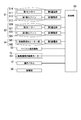
| Application Number | Priority Date | Filing Date | Title |
|---|---|---|---|
| EP21743647.6A EP4095440A4 (en) | 2020-01-21 | 2021-01-14 | Cooker |
| CA3165353A CA3165353A1 (en) | 2020-01-21 | 2021-01-14 | Heating cooking apparatus |
| JP2021573108A JPWO2021149585A1 (en) | 2020-01-21 | 2021-01-14 | |
| US17/793,644 US20230092833A1 (en) | 2020-01-21 | 2021-01-14 | Heating cooking apparatus |
Applications Claiming Priority (2)
| Application Number | Priority Date | Filing Date | Title |
|---|---|---|---|
| JP2020007571 | 2020-01-21 | ||
| JP2020-007571 | 2020-01-21 |
Publications (1)
| Publication Number | Publication Date |
|---|---|
| WO2021149585A1 true WO2021149585A1 (en) | 2021-07-29 |
Family
ID=76992311
Family Applications (1)
| Application Number | Title | Priority Date | Filing Date |
|---|---|---|---|
| PCT/JP2021/001062 WO2021149585A1 (en) | 2020-01-21 | 2021-01-14 | Cooker |
Country Status (5)
| Country | Link |
|---|---|
| US (1) | US20230092833A1 (en) |
| EP (1) | EP4095440A4 (en) |
| JP (1) | JPWO2021149585A1 (en) |
| CA (1) | CA3165353A1 (en) |
| WO (1) | WO2021149585A1 (en) |
Citations (3)
| Publication number | Priority date | Publication date | Assignee | Title |
|---|---|---|---|---|
| JP2010190456A (en) * | 2009-02-17 | 2010-09-02 | Mitsubishi Electric Corp | Grill unit and heating cooker including the same |
| JP2017099956A (en) * | 2017-03-01 | 2017-06-08 | 株式会社パロマ | Heating cooker |
| JP2019107327A (en) * | 2017-12-20 | 2019-07-04 | 株式会社ハーマン | grill |
Family Cites Families (3)
| Publication number | Priority date | Publication date | Assignee | Title |
|---|---|---|---|---|
| US4335292A (en) * | 1979-05-09 | 1982-06-15 | Matsushita Electric Industrial Co., Ltd. | High frequency oven with drawer type door |
| JPH07113526A (en) * | 1993-10-19 | 1995-05-02 | Matsushita Electric Ind Co Ltd | High-frequency heating device |
| CA2940468C (en) * | 2014-08-29 | 2019-01-15 | Sharp Kabushiki Kaisha | Heating cooker |
-
2021
- 2021-01-14 JP JP2021573108A patent/JPWO2021149585A1/ja active Pending
- 2021-01-14 CA CA3165353A patent/CA3165353A1/en active Pending
- 2021-01-14 US US17/793,644 patent/US20230092833A1/en active Pending
- 2021-01-14 EP EP21743647.6A patent/EP4095440A4/en active Pending
- 2021-01-14 WO PCT/JP2021/001062 patent/WO2021149585A1/en unknown
Patent Citations (3)
| Publication number | Priority date | Publication date | Assignee | Title |
|---|---|---|---|---|
| JP2010190456A (en) * | 2009-02-17 | 2010-09-02 | Mitsubishi Electric Corp | Grill unit and heating cooker including the same |
| JP2017099956A (en) * | 2017-03-01 | 2017-06-08 | 株式会社パロマ | Heating cooker |
| JP2019107327A (en) * | 2017-12-20 | 2019-07-04 | 株式会社ハーマン | grill |
Non-Patent Citations (1)
| Title |
|---|
| See also references of EP4095440A4 * |
Also Published As
| Publication number | Publication date |
|---|---|
| EP4095440A1 (en) | 2022-11-30 |
| CA3165353A1 (en) | 2021-07-29 |
| EP4095440A4 (en) | 2023-07-19 |
| US20230092833A1 (en) | 2023-03-23 |
| JPWO2021149585A1 (en) | 2021-07-29 |
Similar Documents
| Publication | Publication Date | Title |
|---|---|---|
| JP7398950B2 (en) | heating cooker | |
| US6953920B2 (en) | Combination microwave oven and steamer | |
| CA1130395A (en) | Energy supply structure for combined resistance heater for h.f. heater oven | |
| CA2987555C (en) | Cooking apparatus | |
| WO2021149585A1 (en) | Cooker | |
| US7271373B2 (en) | Microwave oven | |
| KR20000075155A (en) | Microwave oven having a heater | |
| WO2022153942A1 (en) | Cooking device | |
| WO2022113998A1 (en) | Heating cooker | |
| KR100633173B1 (en) | Structure of machine room for Electric oven | |
| JP2007078248A (en) | Floor placement type cooker | |
| WO2021020389A1 (en) | Heating cooker | |
| US6686575B2 (en) | Microwave oven having side wave dispersing unit | |
| WO2021033687A1 (en) | Drawer-type heat cooker | |
| WO2022124299A1 (en) | Cooker | |
| WO2021157559A1 (en) | Heating cooking device | |
| WO2022181538A1 (en) | Thermal cooker | |
| WO2021020345A1 (en) | Heating cooking device | |
| WO2021020343A1 (en) | Heating cooker | |
| WO2021145380A1 (en) | Cooking apparatus | |
| WO2021020390A1 (en) | Heating cooker | |
| KR100277966B1 (en) | Microwave blower fan | |
| WO2022138629A1 (en) | Heat cooker | |
| KR100572601B1 (en) | Microwave oven | |
| WO2021153611A1 (en) | Heating cooker |
Legal Events
| Date | Code | Title | Description |
|---|---|---|---|
| 121 | Ep: the epo has been informed by wipo that ep was designated in this application |
Ref document number: 21743647 Country of ref document: EP Kind code of ref document: A1 |
|
| ENP | Entry into the national phase |
Ref document number: 2021573108 Country of ref document: JP Kind code of ref document: A |
|
| ENP | Entry into the national phase |
Ref document number: 3165353 Country of ref document: CA |
|
| NENP | Non-entry into the national phase |
Ref country code: DE |
|
| ENP | Entry into the national phase |
Ref document number: 2021743647 Country of ref document: EP Effective date: 20220822 |