WO2021149537A1 - 管理装置、車載装置の識別情報割り当て方法、車載システム、及びデータ構造 - Google Patents
管理装置、車載装置の識別情報割り当て方法、車載システム、及びデータ構造 Download PDFInfo
- Publication number
- WO2021149537A1 WO2021149537A1 PCT/JP2021/000687 JP2021000687W WO2021149537A1 WO 2021149537 A1 WO2021149537 A1 WO 2021149537A1 JP 2021000687 W JP2021000687 W JP 2021000687W WO 2021149537 A1 WO2021149537 A1 WO 2021149537A1
- Authority
- WO
- WIPO (PCT)
- Prior art keywords
- vehicle
- identification information
- frame
- response frame
- request frame
- Prior art date
- Legal status (The legal status is an assumption and is not a legal conclusion. Google has not performed a legal analysis and makes no representation as to the accuracy of the status listed.)
- Ceased
Links
Images








Classifications
-
- H—ELECTRICITY
- H04—ELECTRIC COMMUNICATION TECHNIQUE
- H04L—TRANSMISSION OF DIGITAL INFORMATION, e.g. TELEGRAPHIC COMMUNICATION
- H04L12/00—Data switching networks
- H04L12/28—Data switching networks characterised by path configuration, e.g. LAN [Local Area Networks] or WAN [Wide Area Networks]
-
- H—ELECTRICITY
- H04—ELECTRIC COMMUNICATION TECHNIQUE
- H04L—TRANSMISSION OF DIGITAL INFORMATION, e.g. TELEGRAPHIC COMMUNICATION
- H04L12/00—Data switching networks
- H04L12/28—Data switching networks characterised by path configuration, e.g. LAN [Local Area Networks] or WAN [Wide Area Networks]
- H04L12/40—Bus networks
-
- B—PERFORMING OPERATIONS; TRANSPORTING
- B60—VEHICLES IN GENERAL
- B60R—VEHICLES, VEHICLE FITTINGS, OR VEHICLE PARTS, NOT OTHERWISE PROVIDED FOR
- B60R16/00—Electric or fluid circuits specially adapted for vehicles and not otherwise provided for; Arrangement of elements of electric or fluid circuits specially adapted for vehicles and not otherwise provided for
- B60R16/02—Electric or fluid circuits specially adapted for vehicles and not otherwise provided for; Arrangement of elements of electric or fluid circuits specially adapted for vehicles and not otherwise provided for electric constitutive elements
- B60R16/023—Electric or fluid circuits specially adapted for vehicles and not otherwise provided for; Arrangement of elements of electric or fluid circuits specially adapted for vehicles and not otherwise provided for electric constitutive elements for transmission of signals between vehicle parts or subsystems
-
- H—ELECTRICITY
- H04—ELECTRIC COMMUNICATION TECHNIQUE
- H04L—TRANSMISSION OF DIGITAL INFORMATION, e.g. TELEGRAPHIC COMMUNICATION
- H04L41/00—Arrangements for maintenance, administration or management of data switching networks, e.g. of packet switching networks
- H04L41/08—Configuration management of networks or network elements
- H04L41/0803—Configuration setting
- H04L41/0806—Configuration setting for initial configuration or provisioning, e.g. plug-and-play
-
- H—ELECTRICITY
- H04—ELECTRIC COMMUNICATION TECHNIQUE
- H04L—TRANSMISSION OF DIGITAL INFORMATION, e.g. TELEGRAPHIC COMMUNICATION
- H04L43/00—Arrangements for monitoring or testing data switching networks
- H04L43/08—Monitoring or testing based on specific metrics, e.g. QoS, energy consumption or environmental parameters
- H04L43/0805—Monitoring or testing based on specific metrics, e.g. QoS, energy consumption or environmental parameters by checking availability
- H04L43/0811—Monitoring or testing based on specific metrics, e.g. QoS, energy consumption or environmental parameters by checking availability by checking connectivity
-
- H—ELECTRICITY
- H04—ELECTRIC COMMUNICATION TECHNIQUE
- H04W—WIRELESS COMMUNICATION NETWORKS
- H04W8/00—Network data management
-
- H—ELECTRICITY
- H04—ELECTRIC COMMUNICATION TECHNIQUE
- H04L—TRANSMISSION OF DIGITAL INFORMATION, e.g. TELEGRAPHIC COMMUNICATION
- H04L12/00—Data switching networks
- H04L12/28—Data switching networks characterised by path configuration, e.g. LAN [Local Area Networks] or WAN [Wide Area Networks]
- H04L12/40—Bus networks
- H04L2012/40208—Bus networks characterized by the use of a particular bus standard
- H04L2012/40215—Controller Area Network CAN
Definitions
- This disclosure relates to a management device, an identification information allocation method for an in-vehicle device, an in-vehicle system, and a data structure.
- This application claims priority based on Japanese Application No. 2020-007269 filed on January 21, 2020, and incorporates all the contents described in the Japanese application.
- a unique identification number is assigned to each in-vehicle device connected to the in-vehicle network.
- an in-vehicle network such as CAN (Controller Area Network) and FlexRay, CAN ID, frame ID, etc., which are identification information of the in-vehicle device, are used.
- the identification information must be uniquely defined in the in-vehicle network. For example, when an in-vehicle device is added to an in-vehicle network, it is necessary to assign identification information to the added in-vehicle device so as not to overlap with other in-vehicle devices.
- Patent Document 1 discloses a method of dynamically assigning an identification number to an ECU (Electronic Control unit) in an in-vehicle network.
- each ECU stores a common number table in which a plurality of integer numbers are registered, determines one number from the common number table, and determines the determined number and the uniqueness of the own machine.
- the ID and the ID are transmitted to the management ECU.
- the management ECU determines whether or not there is a duplicate number among the numbers transmitted by each ECU, and if they do not overlap, the transmitted number is assigned as an identification number of each ECU, and if they overlap, the number is minimized.
- Assigned to the ECU with a unique ID The ECU whose unique ID is not the minimum determines the number again from the common number table and transmits it to the management ECU.
- the method of assigning identification information of an in-vehicle device is a method of assigning identification information of an in-vehicle device connected to an in-vehicle network, and a management device connected to the in-vehicle network assigns a unique ID of the in-vehicle device.
- a step of receiving a request frame for giving identification information from the vehicle-mounted device, a step of the management device generating a response frame including the identification information assigned to the received request frame, and the management device. Includes a step of transmitting the generated response frame to the vehicle-mounted device that is the source of the request frame.
- An in-vehicle system includes a management device connected to an in-vehicle network and an in-vehicle device connected to the in-vehicle network, and the in-vehicle device includes an identification unique ID of the in-vehicle device.
- the management device includes a first transmitting unit that transmits a request frame for giving information, and the management device includes a second receiving unit that receives the request frame transmitted from the in-vehicle device, and the request received by the second receiving unit.
- a generation unit that generates a response frame including identification information assigned to the frame, and a second transmission unit that transmits the response frame generated by the generation unit to the vehicle-mounted device that is the source of the request frame.
- the in-vehicle device includes, the first receiving unit that receives the response frame transmitted from the management device, and the identification information included in the response frame received by the first receiving unit of the own device. It further includes a setting unit for setting as identification information.
- the data structure according to one aspect of the present disclosure is a data structure used in a request frame for an in-vehicle device connected to an in-vehicle network to request the allocation of identification information, and includes an ID area and a data area.
- the ID area stores common identification information in the vehicle-mounted network
- the data area stores the unique ID of the vehicle-mounted device that requests the allocation of the identification information and the number of requests for the identification information.
- the data structure according to another aspect of the present disclosure is a data structure used for a response frame for responding to a request for allocation of identification information by an in-vehicle device connected to an in-vehicle network, and includes an ID area and a data area.
- ID area common identification information in the vehicle-mounted network is stored, and in the data area, a unique ID of the vehicle-mounted device requesting the allocation of the identification information and the identification information assigned to the vehicle-mounted device are stored.
- the data area is stored, and the number of the identification information requested by the in-vehicle device is stored.
- the present disclosure can be realized not only as a management device having the above-mentioned characteristic configuration, but also as a method for allocating identification information of an in-vehicle device in which characteristic processing in the management device is a step, or such a step.
- a part or all of the management device can be realized as a semiconductor integrated circuit, or can be realized as an in-vehicle system including the management device.
- the present disclosure can also be realized as a data structure used in the above-mentioned method of allocating identification information of an in-vehicle device.
- the management device is a management device that assigns identification information to an in-vehicle device connected to an in-vehicle network, and requests a frame for adding identification information including a unique ID of the in-vehicle device.
- a receiving unit that receives from the receiving unit, a generating unit that generates a response frame including identification information assigned to the request frame received by the receiving unit, and the response frame generated by the generating unit are requested. It includes a transmission unit that transmits the frame to the in-vehicle device that is the transmission source of the frame.
- the identification information can be assigned so that the device different from the in-vehicle device does not overlap between the in-vehicle devices. That is, since the device to which the identification information is assigned can identify the identification information assigned to each in-vehicle device, the identification information assigned to one in-vehicle device can be prevented from being assigned to another in-vehicle device. Therefore, when a plurality of in-vehicle devices request the allocation of identification information at the same time or one in-vehicle device requests the allocation of a plurality of identification information, it is possible to suppress an increase in the time required for assigning the identification number. Can be done.
- the request frame may further include the number of requested identification information
- the response frame may include the number of identification information different from each other.
- the response frame includes a normal response frame and an abnormal response frame
- the generation unit is assigned the identification information when the identification information is assigned.
- the normal response frame including the above is generated, the generation unit generates the abnormal response frame not including the identification information when the identification information is not assigned, and the transmission unit is generated by the generation unit.
- the normal response frame or the abnormal response frame may be transmitted to the in-vehicle device of the transmission source.
- the in-vehicle device can acquire the identification information included in the normal response frame.
- the in-vehicle device can take necessary measures such as transmitting the request frame again without acquiring the identification information.
- the management device is received by a storage unit that stores a correspondence table showing the correspondence relationship between the unique ID of the vehicle-mounted device and the channel of the network bus to which the vehicle-mounted device is connected, and the receiving unit.
- a connection state determination unit that determines whether or not the correspondence between the unique ID included in the request frame and the channel of the network bus to which the request frame is transmitted matches the correspondence shown in the correspondence table.
- the generation unit further comprises, and the connection state determination unit indicates in the table the correspondence between the unique ID included in the request frame and the channel to which the request frame is transmitted. When it is determined that the correspondence matches, the normal response frame is generated, and the generation unit generates the unique ID included in the request frame and the channel on which the request frame is transmitted by the connection state determination unit.
- the abnormal response frame may be generated.
- the in-vehicle device is not connected to the correct channel, it is possible to notify the connection abnormality by transmitting an abnormal response frame without assigning the identification information to the in-vehicle device.
- the request frame may include common identification information that is common identification information in the vehicle-mounted network and is identification information dedicated to allocation of identification information.
- the frame defined by the in-vehicle network protocol is provided with an area for storing the identification information of the in-vehicle device, but the in-vehicle device before the identification information is assigned does not have the identification information to be stored. Therefore, by storing the common identification information in the request frame, the identification information of the in-vehicle device is not required, and the in-vehicle device such as the management device that has received the request frame recognizes the frame as a frame used for assigning the identification information. can do.
- the request frame may further include an identifier dedicated to the request of the identification information.
- an in-vehicle device such as a management device that has received the request frame can distinguish between the request frame and the response frame.
- the response frame may include the common identification information.
- the in-vehicle device that has received the response frame can recognize the frame as a frame used for assigning the identification information.
- the response frame may further include an identifier dedicated to the response to the request for the identification information.
- the management device may further include an allocation unit that allocates identification information to the request frame received by the reception unit. As a result, the management device can assign the identification information to the request frame without inquiring to the external device.
- the method of allocating the identification information of the in-vehicle device is the method of allocating the identification information of the in-vehicle device connected to the in-vehicle network, and the management device connected to the in-vehicle network has the unique ID of the in-vehicle device.
- the device includes a step of transmitting the generated response frame to the in-vehicle device that is the source of the request frame.
- the identification information can be assigned so that the device different from the in-vehicle device does not overlap between the in-vehicle devices. That is, since the device to which the identification information is assigned can identify the identification information assigned to each in-vehicle device, the identification information assigned to one in-vehicle device can be prevented from being assigned to another in-vehicle device. Therefore, when a plurality of in-vehicle devices request the allocation of identification information at the same time or one in-vehicle device requests the allocation of a plurality of identification information, it is possible to suppress an increase in the time required for assigning the identification number. Can be done.
- the in-vehicle system includes a management device connected to the in-vehicle network and an in-vehicle device connected to the in-vehicle network, and the in-vehicle device includes a unique ID of the in-vehicle device.
- the management device includes a first transmitting unit that transmits a request frame for giving identification information, and the management device includes a second receiving unit that receives the request frame transmitted from the in-vehicle device, and the second receiving unit that is received by the second receiving unit.
- a generation unit that generates a response frame including identification information assigned to the request frame, and a second transmission unit that transmits the response frame generated by the generation unit to the in-vehicle device that is the source of the request frame.
- the in-vehicle device includes, the first receiving unit that receives the response frame transmitted from the management device, and the identification information included in the response frame received by the first receiving unit. Further includes a setting unit for setting as identification information of the above.
- the identification information can be assigned so that the device different from the in-vehicle device does not overlap between the in-vehicle devices. That is, since the device to which the identification information is assigned can identify the identification information assigned to each in-vehicle device, the identification information assigned to one in-vehicle device can be prevented from being assigned to another in-vehicle device.
- the data structure according to the present embodiment is a data structure used for a request frame for an in-vehicle device connected to an in-vehicle network to request the allocation of identification information, and includes an ID area and a data area.
- the ID area stores common identification information in the vehicle-mounted network
- the data area stores the unique ID of the vehicle-mounted device that requests the allocation of the identification information and the number of requests for the identification information.
- the in-vehicle device such as the management device that has received the request frame can recognize the frame as the request frame, and can further specify the number of required identification information. Therefore, it is possible to add a necessary number of identification information to the in-vehicle device that has transmitted the request frame.
- the data structure according to the present embodiment is a data structure used for a response frame for responding to a request for allocation of identification information by an in-vehicle device connected to an in-vehicle network, and includes an ID area and a data area.
- ID area common identification information in the vehicle-mounted network is stored, and in the data area, a unique ID of the vehicle-mounted device requesting the allocation of the identification information and the identification information assigned to the vehicle-mounted device are stored.
- the data area is stored, and the number of the identification information requested by the in-vehicle device is stored.
- the in-vehicle device that has received the response frame can recognize the frame as the response frame, and can add one or more identification information to one in-vehicle device at a time.
- the identification information management system is a system that manages identification information of an in-vehicle device connected to an in-vehicle network mounted on a vehicle.
- the identification information is used to identify each in-vehicle device (node) in the in-vehicle network.
- the CAN ID is the identification information.
- the CAN ID is used as the identification information.
- the identification information is not limited to the CAN ID.
- the ID of the vehicle-mounted device included in the frame ID is the identification information
- the ID of the vehicle-mounted device included in the PID (Protected Identifier) field of the header is the identification information. ..
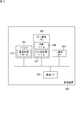
- FIG. 1 is a schematic diagram for explaining an example of the identification information management system according to the present embodiment.
- the identification information management system 100 includes a plurality of vehicles 10 and a server 40.
- the vehicle 10 is equipped with a wireless communication device (out-of-vehicle communication device 202 described later), and can perform wireless communication with the base station 20 (or roadside unit).
- the base station 20 is connected to the Internet 30, and the server 40 is also connected to the Internet 30.
- the vehicle 10 is capable of data communication with the server 40.
- the server 40 has a database (ID database 406, see FIG. 5), and stores the CAN ID assigned to each in-vehicle device for each vehicle 10.
- the vehicle 10 requests the server 40 to assign a CAN ID when it is necessary to assign a CAN ID to the in-vehicle device, such as when a new in-vehicle device is connected to the in-vehicle network.
- the server 40 assigns the CAN ID to the in-vehicle device and registers the CAN ID in the database in response to the request.
- the server 40 transmits the assigned CAN ID to the requesting vehicle 10. In this way, the CAN ID of the in-vehicle device of each vehicle 10 is managed.
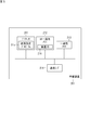
- FIG. 2 is a block diagram showing an example of the configuration of the in-vehicle system according to the present embodiment.
- the in-vehicle system 200 includes, for example, an in-vehicle device 201_1,201_2,201_3, ..., a management device 300, and an external communication device 202.
- the in-vehicle device 201_1,201_2,201_3, ... Is also collectively referred to as the in-vehicle device 201.
- Each of the in-vehicle devices 201 is a power train and drive train control device such as an engine control device, an inverter control device, a steering control device, and a brake control device, and is an air conditioner control device, a navigation device, a display device, and a room. It is a control device for in-vehicle equipment such as a light control device and a power window control device.
- Each of the in-vehicle devices 201 is connected to the in-vehicle network 400.
- the vehicle-mounted network 400 includes a plurality of CAN buses. One CAN bus is an independent data transmission line and a communication channel. In the example shown in FIG. 2, the vehicle-mounted network 400 has six channels 400_1, 400_2, 400_3, 400_4, 400_5, 400_6. Each of the vehicle-mounted devices 201 is connected to at least one of channels 400_1, 400_2, 400_3, 400_4, 400-5, 400_6. In the example shown in FIG.
- the in-vehicle device 201_1 is connected to the channel 400_1,400_2, the in-vehicle device 201_2 is connected to the channel 400_2,400_3, the in-vehicle device 201_3 is connected to the channel 400_1,400_2,400_3,400_4, and the in-vehicle device 201_2 is connected.
- Is connected to channels 400_3, 400_4, the in-vehicle device 201_5 is connected to channels 400_2, 400_4, and each of the in-vehicle devices 201_6, 201_7, 201_8 is connected to channels 400_5, 400_6.
- the management device 300 receives the request frame from the in-vehicle device 201 and requests the server 40 to assign the CAN ID.
- the management device 300 When the CAN ID is notified from the server 40, the management device 300 generates a response frame including the assigned CAN ID and transmits it to the in-vehicle device 201 of the request source. That is, the management device 300 mediates between the in-vehicle device 201 and the server 40.
- the management device 300 is connected to each channel 400_1, 400_2, 400_3 of the in-vehicle network 400.
- the management device 300 is a relay device, and relays communication between in-vehicle devices 201 connected to different channels. Further, when the management device 300 receives the request frame from the in-vehicle device 201, the management device 300 determines whether or not the channel to which the in-vehicle device 201 of the transmission source is connected matches the channel to which the in-vehicle device 201 should be connected. Execute the connection status judgment process.
- the management device 300 When the connection state is normal, that is, when the in-vehicle device 201 is connected to the correct channel, the management device 300 generates a normal response frame including the assigned CAN ID, and requests the normal response frame from the request frame source. It is transmitted to the in-vehicle device 201. On the other hand, when the in-vehicle device 201 is not connected to the correct channel, the management device 300 generates an abnormal response frame that does not include the CAN ID, and transmits the abnormal response frame to the in-vehicle device 201 that is the source of the request frame.
- An external communication device 202 is connected to the management device 300.
- the out-of-vehicle communication device 202 can perform wireless communication.
- the out-of-vehicle communication device 202 wirelessly communicates with an out-of-vehicle device such as a terminal or a server 40 via the base station 20.
- a central device 203 is connected to the management device 300.
- the central device 203 includes a user interface, that is, an input unit such as a touch sensor, a switch, and a microphone, and an output unit such as a monitor and a speaker.
- the management device 300 transmits an output command to the central device 203.
- the central device 203 outputs a screen or audio.
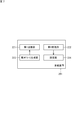
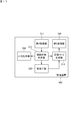
- FIG. 3 is a block diagram showing an example of the configuration of the management device according to the present embodiment.
- the management device 300 includes a processor 301, a non-transient memory 302, a transient memory 303, and a communication interface 304.
- the transient memory 303 is, for example, a volatile memory such as SRAM (Static Random Access Memory) or DRAM (Dynamic Random Access Memory).
- the non-transient memory 302 is, for example, a non-volatile memory such as a flash memory, a hard disk, or a ROM (Read Only Memory).
- the non-transient memory 302 stores data used for executing the communication management program 305 and the communication management program 305, which are computer programs.
- the management device 300 is configured to include a computer, and each function of the management device 300 is exhibited by executing a communication management program 305, which is a computer program stored in the storage device of the computer, by a processor 301, which is a CPU. Will be done.
- the communication management program 305 can be stored in a recording medium such as a flash memory, a ROM, or a CD-ROM.
- the processor 301 executes the communication management program 305 and executes a communication management process as described later.
- the processor 301 is not limited to the CPU.
- the processor 301 may be, for example, a hardware logic circuit such as an ASIC (Application Specific Integrated Circuit), a gate array, or an FPGA (Field Programmable Gate Array).
- the hardware logic circuit is configured to be able to execute the same processing as the communication management program 305.
- the non-transient memory 302 is provided with a relay table 306 and a channel management table 307.
- the relay table 306 is a table for managing channels used for each CAN ID.
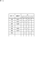
- FIG. 4 is a diagram showing an example of the configuration of the relay table 306.
- the relay table 306 the CAN ID and the channel used for transmitting and receiving frames are associated with each other.
- “r” indicates a channel used by the management device 300 for receiving the frame
- “s” indicates a channel used for transmitting the frame from the management device 300 to the in-vehicle device 201.
- the reception channel number of the frame whose source is CAN ID "100” is "0", and the transmission channel numbers of the frame whose destination is CAN ID "100" are "2" and "3". Is.
- the reception channel number of the frame whose source is CAN ID "110” is “0”
- the transmission channel number of the frame whose destination is CAN ID "110” is "1" and ". 2 ”.
- the reception channel number of the frame whose source is CAN IDs "200” and “250” is "1”
- the transmission channel number of the frame whose destination is CAN IDs "200” and “250” is "1". 2 ”.
- the reception channel number of the frame whose transmission source is CAN ID "300” is “2”, and the transmission channel number of the frame whose destination is CAN ID "300” is "4".
- the relay table 306 is used for relaying communication between the in-vehicle device 201 and another device (for example, another in-vehicle device 201 or an external device of the vehicle 10). For example, consider a case where a CAN frame with CAN ID "100" is transmitted from one in-vehicle device 201 to another in-vehicle device 201.
- the CAN frame includes the CAN ID "100" as the destination.
- the management device 300 receives the CAN frame on the channel “1” and extracts the destination CAN ID “100” from the CAN frame.
- the management device 300 refers to the relay table 306, identifies that the transmission channel numbers of the CAN ID “100” are “2” and “3”, and transmits the CAN frame to the selected channel.
- the channel management table 307 is used for the connection state determination process described above.
- the channel management table 307 is a correspondence table showing the correspondence relationship between the device ID of the vehicle-mounted device 201 and the channel to which the vehicle-mounted device 201 should be connected.
- the "device ID" is unique identification information assigned to each vehicle-mounted device 201, such as the serial number and MAC address of the vehicle-mounted device 201.
- the channel management table 307 will be described later.
- the communication interface 304 is connected to a communication line connected to each channel 400_1, 400_2, 400_3 of the in-vehicle network 400, the external communication device 202, and the central device 203.
- FIG. 5 is a block diagram showing an example of the configuration of the in-vehicle device according to the present embodiment.
- the vehicle-mounted device 201 includes a processor 211, a non-transient memory 212, a transient memory 213, and a communication interface 214.
- the non-transient memory 212 stores data used for executing the communication setting program 215 and the communication setting program 215, which are computer programs.
- the in-vehicle device 201 is configured to include a computer, and a function related to setting the CAN ID of the in-vehicle device 201 is executed by a processor 211 in which the communication setting program 215, which is a computer program stored in the storage device of the computer, is a CPU. It is demonstrated by doing.
- the communication setting program 215 can be stored in a recording medium such as a flash memory, a ROM, or a CD-ROM.
- the processor 211 executes the communication setting program 215 and executes the communication setting process as described later. Further, the device ID 216 of the own device is stored in the non-transient memory 212.
- the processor 211 is not limited to the CPU.
- the processor 211 may be, for example, a hardware logic circuit such as an ASIC, a gate array, or an FPGA.
- the hardware logic circuit is configured to be able to execute the same processing as the communication setting program 215.
- the communication interface 214 is connected to one or more of the channels 400_1, 400_2, 400_3 of the in-vehicle network 400.
- FIG. 6 is a block diagram showing an example of a server configuration according to the present embodiment.
- the server 40 includes a processor 401, a non-transient memory 402, a transient memory 403, and a communication interface 404.
- the non-transient memory 402 stores data used for executing the ID allocation program 405 and the ID allocation program 405, which are computer programs.
- the server 40 is configured to include a computer, and the function related to the assignment of the CAN ID for the server in-vehicle device 201 is executed by the processor 401 in which the ID allocation program 405, which is a computer program stored in the storage device of the computer, is a CPU. It is demonstrated by being done.
- the ID allocation program 405 can be stored in a recording medium such as a flash memory, a ROM, or a CD-ROM.
- the processor 401 executes the ID allocation program 405 and executes an ID allocation process as described later.
- IDDB406 An ID database (hereinafter referred to as "IDDB") 406 is provided in the non-transient memory 402. IDDB406 is used for ID allocation processing. IDDB406 is a database for managing the CAN ID assigned to the in-vehicle device 201 for each vehicle 10. IDDB406 will be described later.
- FIG. 7 is a functional block diagram showing an example of the functions of the in-vehicle device according to the present embodiment.
- the in-vehicle device 201 has functions of a first transmission unit 221, a first reception unit 222, a request frame generation unit 223, and a setting unit 224.
- the request frame generation unit 223 generates a request frame for assigning a CAN ID. For example, when a new vehicle-mounted device 201 is connected to the vehicle-mounted network 400, the vehicle-mounted device 201 requests the management device 300 to assign a CAN ID when the vehicle-mounted system 200 is started. At this time, a request frame is generated, and the request frame is transmitted to the management device 300.
- the request frame generation unit 223 is mainly realized by the processor 211.
- FIG. 8 is a schematic diagram showing the frame format of CAN.
- FIG. 8 shows the data frame structure in the standard format of CAN. The upper line in the figure indicates recessive, and the lower line indicates dominant.
- CAN data frames include SOF (Start Of Frame), CAN ID, RTR (Remote transmission Request), control field, data field, CRC (Cyclic Redundancy Check) sequence, CRC delimiter, and ACK ( Acknowledgement) slot, ACK delimiter, and EOF (EndOfFrame) fields are included.
- SOF indicates the start of the frame.
- the CAN ID is used to identify the type of the in-vehicle device 201 and the frame.
- the RTR is used to distinguish between data frames and remote frames.
- the RTR is dominant.
- Information used for communication control is stored in the control field.
- a maximum of 8 bytes of actual data (payload) is stored in the data field.
- the CRC sequence and CRC delimiter are collectively called a CRC field, and a kind of error detection code is stored in the CRC field.
- the ACK slot and the ACK delimiter are collectively called an ACK field, and the ACK field stores information indicating whether or not the CRC field portion can be normally received.
- EOF indicates the end of the frame.
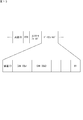
- FIG. 9 is a schematic diagram showing an example of the request frame according to the present embodiment.
- a common ID (for example, 0x6FF) is stored in the CAN ID field of the frame related to the allocation of the CAN ID.
- the common ID is used to identify that it is a frame (request frame and response frame) related to the allocation of the CAN ID.
- the common ID is information common to the in-vehicle network 400. That is, all the vehicle-mounted devices 201 and the management device 300 connected to the vehicle-mounted network 400 use one common ID when transmitting and receiving frames related to the allocation of the CAN ID.
- the device that has received the request frame identifies that the frame is a frame related to the allocation of the CAN ID by referring to the common ID in the CAN ID field.
- the data field of the request frame includes each data of "device ID" and "number of request IDs".
- the CAN ID assigned to one in-vehicle device 201 is not limited to one, and may be multiple.
- the number of requested IDs is the number of CAN IDs required by the in-vehicle device 201.
- an identifier indicating that the frame is the request frame that is, an identifier dedicated to the request of the CAN ID (“00” in the example of FIG. 9) is included.
- the device that has received the request frame identifies that the frame is the request frame by referring to this identifier.
- the request frame may be applied to CAN FD.
- the common ID is stored in the CAN ID field in the CAN FD frame format, and the "device ID" and the "number of requested IDs" are stored in the data field.
- the first transmission unit 221 transmits the request frame generated by the request frame generation unit 223 through the CAN bus (channel) connected to the in-vehicle device 201.
- the first transmission unit 221 is mainly realized by the communication interface 214.
- the management device 300 transmits a response frame for the request frame.
- the first receiving unit 222 receives the response frame through the CAN bus (channel) connected to the in-vehicle device 201.
- the first receiving unit 222 is mainly realized by the communication interface 214.
- the setting unit 224 sets the CAN ID included in the normal response frame as the CAN ID of the own device.
- the CAN ID of the own device is stored in, for example, the non-transient memory 212.
- the CAN ID is used as information for identifying the vehicle-mounted device 201.
- the setting unit 224 is mainly realized by the processor 211.
- FIG. 10 is a functional block diagram showing an example of the functions of the management device according to the present embodiment.
- the management device 300 has functions of a second receiving unit 311, a connection state determination unit 312, an ID inquiry unit 313, a response frame generation unit 314, a second transmitting unit 315, and an output command unit 316.
- the second receiving unit 311 receives the request frame transmitted from the in-vehicle device 201 through the CAN bus (channel).
- the second receiving unit 311 is mainly realized by the communication interface 304.
- connection state determination unit 312 the correspondence between the unique ID included in the request frame received by the second reception unit 311 and the channel on which the request frame is transmitted matches the correspondence relationship shown in the channel management table 307. Judge whether or not.
- FIG. 11 is a diagram showing an example of the configuration of the channel management table.
- the channel management table 307 is a table that stores the channel number of the vehicle-mounted network 400 and the range of the device ID in association with each other.
- the device ID is shown in hexadecimal.
- the range of the device ID from "0x00" to "0x2F” corresponds to the channel "0". That is, the connection destination of the in-vehicle device 201 whose device ID is from “0x00" to "0x2F" is the channel "0".
- the channel "1" corresponds to the range of device IDs from "0x30" to "0x5F".
- Channel “2" corresponds to the range of device IDs from “0x60” to “0x8F”.
- Channel “3” corresponds to the range of device IDs from “0x90” to “0xBF”.
- Channel “4" corresponds to the range of device IDs from "0xC0" to "0xEF”.
- the connection state determination unit 312 queries the channel management table 307 for the device ID included in the request frame and the number of the channel on which the request frame is transmitted. That is, the connection state determination unit 312 specifies the range of the device ID corresponding to the number of the channel on which the request frame is transmitted by the channel management table 307, and the device ID included in the request frame is the range of the specified device ID. Judge whether or not it is included in. When the device ID included in the request frame is within the range of the specified device ID, the connection state determination unit 312 determines that the vehicle-mounted device 201 that is the source of the request frame is connected to an appropriate channel. ..
- connection state determination unit 312 determines that the in-vehicle device 201 that is the source of the request frame is connected to an inappropriate channel. to decide.
- the connection state determination unit 312 is mainly realized by the processor 301.
- the ID inquiry unit 313 requests the server 40 to assign the CAN ID. More specifically, the ID inquiry unit 313 requests the allocation of CAN IDs for the number of request IDs included in the request frame. This request includes the device ID of the vehicle-mounted device 201 that is the source of the request frame and the number of request IDs.
- the server 40 receives the CAN ID allocation request, the server 40 allocates the CAN IDs for the number of requested IDs.
- FIG. 12 is a diagram showing an example of the configuration of IDDB406.
- the IDDB 406 stores the CAN ID and the device ID in association with each other. Further, the IDDB 406 stores the channel number used for each CAN ID.
- “r” indicates a channel (reception channel) used by the management device 300 to receive the frame
- “s” indicates a channel (transmission channel) used to transmit the frame from the management device 300 to the in-vehicle device 201. ) Is shown. That is, in the IDDB 406 shown in FIG.
- the frame is transmitted from which channel (reception channel). Indicates which channel (transmission channel) to relay to.
- the CAN ID is assigned to the device ID
- the CAN ID, the device ID, and the transmission channel and reception channel numbers are stored in IDDB406 in association with each other.
- the device ID “0x10” is registered for the CAN ID “100”, and the transmission channel “0” and the reception channels “2” and “3” are registered.
- the device ID "0x40" is registered for the CAN ID "200”, and the transmission channel "1" and the reception channel "2" are registered.
- the device ID "0x50” is registered for the CAN ID "250", and the transmission channel “1” and the reception channel “2" are registered.
- the device ID "0x70” is registered for the CAN ID "300”, and the transmission channel “2” and the reception channel “4" are registered.
- a device ID to which a CAN ID is not assigned is not registered in IDDB406. If the device ID corresponding to the CAN ID does not exist, the device ID corresponding to the CAN ID is left blank. In the example of FIG. 12, since the device ID corresponding to the CAN ID “210” does not exist, the device ID for the CAN ID “210” is blank.
- the transmission channel number and the reception channel number are not registered for the CAN ID not assigned to the device ID (that is, the unused CAN ID), and the transmission channel number and the transmission channel number and the channel number are not registered.
- the receiving channel number may be registered.
- the channel used by the management device 300 is determined in the following two cases. (1) The channel is dynamically determined in consideration of the usage status of the channel in the in-vehicle network 400 (hereinafter, referred to as "dynamic channel determination"). (2) From the viewpoint of suppressing the bias of the CAN bus load, the channel is determined in advance for the CAN ID (hereinafter referred to as "static channel determination"). In a specific example, whether dynamic channel determination or static channel determination is used is determined for each CAN ID. However, the present invention is not limited to this, and either dynamic channel determination or static channel determination may be used for all CAN IDs.
- the transmission channel number and the reception channel number are registered for the CAN ID in which the device ID is blank (that is, in the record in which the device ID is blank). do not have. In the example of FIG. 12, the transmission channel and the reception channel corresponding to the CAN ID “210” are not registered.
- the new in-vehicle device 201 that is, the CAN ID is not assigned transmits the request frame to the management device 300, and the management device 300 that receives the request frame uses the channel in the in-vehicle network 400.
- the channel to be used in the communication related to the vehicle-mounted device 201 (communication with the vehicle-mounted device 201 as the destination or the transmission source) is determined.
- the management device 300 notifies the server 40 of the determined channel number together with the device ID of the vehicle-mounted device 201.
- the server 40 assigns a CAN ID to the in-vehicle device 201, and registers the device ID, the receiving channel number, and the transmitting channel number in the IDDB 406 in association with the CAN ID.
- the transmission channel number and the reception channel number are registered in advance for the CAN ID whose device ID is blank in IDDB406.
- the transmission channel number “1” and the reception channel number “3” are defined in advance for the CAN ID “350”, and the channel “1” is set in the record of the CAN ID “350”.
- the value of is "r” and the value of channel "3" is "s”.
- the management device 300 that has received the request frame from the new in-vehicle device 201 requests the server 40 for the CAN ID for the in-vehicle device 201, and also requests the allocation of the channel.
- the server 40 assigns a CAN ID to the in-vehicle device 201, and registers the device ID in the IDDB 406 in association with the assigned CAN ID. Further, the server 40 refers to the IDDB 406, specifies a predetermined reception channel number and transmission channel number for the assigned CAN ID, and transmits the specified reception channel number and transmission channel number to the management device 300. do.
- the ID inquiry unit 313 receives the CAN ID notification transmitted from the server 40.
- the ID inquiry unit 313 is mainly realized by the communication interface 304.
- the response frame generation unit 314 is a response frame (normal response frame or abnormal response frame) including the CAN ID assigned to the request frame received by the second receiving unit 311, that is, the CAN ID notified from the server 40. To generate. Specifically, when the device ID included in the request frame is within the range of the specified device ID, the response frame generation unit 314 generates a normal response frame including the CAN ID assigned by the server 40. If the device ID included in the request frame is out of the range of the specified device ID, an abnormal response frame that does not include the CAN ID is generated.
- the response frame generation unit 314 is mainly realized by the processor 301.
- FIG. 13 is a schematic diagram showing an example of a normal response frame according to the present embodiment.
- a common ID is stored in the CAN ID field of the normal response frame.
- the data field of the normal response frame includes each data of "device ID" and assigned "CAN ID". Specifically, the allocated number of CAN IDs is stored in the data field.
- an identifier indicating that the frame is a normal response frame that is, an identifier dedicated to notification of the assigned CAN ID (“01” in the example of FIG. 13) is included.
- the device that has received the normal response frame identifies that the frame is a normal response frame by referring to this identifier.
- FIG. 14 is a schematic diagram showing an example of an abnormal response frame according to the present embodiment.
- a common ID is stored in the CAN ID field of the abnormal response frame.
- the data field of the abnormal response frame includes the data of "device ID". That is, the CAN ID is not included in the data field of the abnormal response frame.
- an identifier indicating that the frame is an abnormal response frame that is, an identifier dedicated to notifying that the CAN ID has not been assigned (“FF” in the example of FIG. 14). Is included.
- the device that has received the abnormal response frame identifies that the frame is an abnormal response frame by referring to this identifier.
- the second transmission unit 315 transmits the response frame (normal response frame or abnormal response frame) generated by the response frame generation unit 314 through the CAN bus (channel) connected to the in-vehicle device 201 that requests the CAN ID. ..
- the second transmission unit 315 is mainly realized by the communication interface 304.
- the output command unit 316 transmits an error output command to the central device 203 when the device ID included in the request frame is out of the range of the specified device ID.
- the central device 203 executes an error output.
- the error output is, for example, display of error information, audio output of error information, output of a buzzer sound, or the like.
- the output command unit 316 is mainly realized by the communication interface 304.
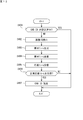
- FIG. 15 is a flowchart showing an example of the procedure of the communication setting process of the in-vehicle device 201 according to the present embodiment
- FIG. 16 is a flowchart showing an example of the procedure of the communication management process of the management device 300 according to the present embodiment. be.
- the processor 211 of the vehicle-mounted device 201 activates the communication setting program 215 (see FIG. 5), for example, when the vehicle-mounted device 201 is activated or when the connection of the vehicle-mounted device 201 to the vehicle-mounted network 400 is detected. As a result, the processor 211 starts the communication setting process. In the communication setting process, the processor 211 first determines whether or not the CAN ID has been set for the own device (step S101). In this process, for example, it is determined whether or not the CAN ID has been set by determining whether or not the CAN ID is stored in the non-transient memory 212.
- step S101 If the CAN ID has already been set (YES in step S101), the processor 211 ends the communication setting process. On the other hand, when the CAN ID is not set (NO in step S101), the processor 211 reads the device ID 216 from the non-transient memory 212 (step S102). Further, the processor 211 generates a request frame including the read device ID 216 (step S103). The processor 211 then causes the generated request frame to be transmitted to the communication interface 214 through a channel connected to the vehicle-mounted device 201 (step S104).
- the processor 301 of the management device 300 activates the communication management program 305 (see FIG. 3), for example, when the in-vehicle device 201 is activated. As a result, the processor 301 starts the communication management process. In the communication management process, the management device 300 receives the request frame transmitted from the vehicle-mounted device 201 (step S201).
- the processor 301 executes the connection state determination process (step S202). That is, in the processor 301, the correspondence between the device ID of the vehicle-mounted device 201 that is the source of the request frame and the channel to which the vehicle-mounted device 201 is connected is the device ID and the channel registered in the channel management table 307. Determine if it matches the correspondence. In this process, the correspondence between the device ID of the in-vehicle device 201 that is the source of the request frame and the channel to which the in-vehicle device 201 is connected is the correspondence between the device ID registered in the channel management table 307 and the channel. If it matches, it is determined that there is no abnormality in the device ID, and if it does not match the correspondence between the device ID registered in the channel management table 307 and the channel, it is determined that there is an abnormality in the device ID. ..
- the processor 301 transmits a CAN ID request to the server 40 (step S203).
- the server 40 assigns a CAN ID to the device ID in response to the request, and notifies the management device 300 of the assigned CAN ID.
- the management device 300 receives the notification of the assigned CAN ID from the server 40 (step S204).
- the management device 300 determines the channel used in the communication regarding the new vehicle-mounted device 201 based on the usage status of the channel in the vehicle-mounted network 400.
- the management device 300 notifies the server 40 of the determined channel number in the request for the CAN ID to the server 40.
- the server 40 assigns a CAN ID to the in-vehicle device 201, and registers the device ID, the receiving channel number, and the transmitting channel number in the IDDB 406 in association with the CAN ID.
- the management device 300 requests the server 40 for a CAN ID for the new in-vehicle device 201 and also requests channel allocation.
- the server 40 assigns a CAN ID to the in-vehicle device 201, and registers the device ID in the IDDB 406 in association with the assigned CAN ID. Further, the server 40 refers to the IDDB 406 and transmits the reception channel number and the transmission channel number predetermined for the assigned CAN ID to the management device 300.
- the processor 301 generates a normal response frame including the received CAN ID (step S205).
- the processor 301 causes the generated normal response frame to be transmitted to the communication interface 214 through the channel connected to the vehicle-mounted device 201 to be transmitted (step S206). Further, the processor 301 registers the CAN ID assigned to the in-vehicle device 201 in the relay table 306 (step S207).
- the processor 301 When dynamic channel determination is used, when registering the CAN ID in the relay table 306, the processor 301 registers the determined transmission channel number and reception channel number in association with the CAN ID. When static channel determination is used, when registering the CAN ID in the relay table 306, the processor 301 registers the transmission channel number and the reception channel number notified from the server 40 in association with the CAN ID. This completes the communication management process.
- the processor 301 determines whether there is an abnormality in the device ID as a result of the connection state determination process (NO in step S202). If there is an abnormality in the device ID as a result of the connection state determination process (NO in step S202), the processor 301 generates an abnormal response frame (step S208). The processor 301 causes the generated abnormal response frame to be transmitted to the communication interface 214 through the channel connected to the vehicle-mounted device 201 to be transmitted (step S209). Further, the processor 301 causes the central device 203 to transmit an error output command to the communication interface 214 (step S210). This completes the communication management process.
- the vehicle-mounted device 201 which is the source of the request frame, receives the response frame (normal response frame or abnormal response frame) transmitted from the management device 300 (step S105).
- the processor 211 determines whether the received response frame is a normal response frame or an abnormal response frame (step S106). That is, the processor 211 determines whether the device ID has an abnormality or no abnormality. If the received frame is an abnormal response frame (NO in step S106), the processor 211 cancels the communication setting process.
- the processor 211 sets the CAN ID included in the received normal response frame as the CAN ID of its own device (step S107). This completes the communication setting process.
- the configuration of the management device 300 is not limited to the configuration of the management device 300 according to the above-described embodiment.
- the management device 300 may have the function of the server 40. That is, the management device 300 may assign the CAN ID to the vehicle-mounted device 201 that has transmitted the request frame.
- the server 40 can be omitted.
- FIG. 17 is a functional block diagram showing a modified example of the function of the management device according to the embodiment.
- the management device 300 shown in FIG. 17 has a function of the allocation unit 320 instead of the ID inquiry unit 313.
- the allocating unit 320 allocates the CAN ID to the request frame received by the second receiving unit 311.
- the allocation unit 320 executes the same ID allocation process as the server 20 described above.
- the management device 300 makes an error when the correspondence relationship between the device ID of the in-vehicle device 201 that is the source of the request frame and the channel on which the request frame is transmitted does not match the correspondence relationship defined in the channel management table 307.
- the configuration for transmitting an output command to the central device 203 has been described, but the present invention is not limited to this. If the correspondence between the device ID of the in-vehicle device 201 that is the source of the request frame and the channel on which the request frame is transmitted does not match the correspondence defined in the channel management table 307, the management device 300 causes an error. Error output such as information display, error information audio output, buzzer sound output, etc. may be performed.
- the common ID would be stored in the CAN ID fields of each of the request frame and response frame, but this is not limited to this.
- the information stored in the CAN ID field may be different between the request frame and the response frame.
- the CAN ID field of the request frame stores the first common ID
- the CAN ID field of the response frame stores the second common ID (however, the first common ID and the second common ID are different from each other). be able to.
- each of the first common ID and the second common ID may be common information in the in-vehicle network 400.
- all the vehicle-mounted devices 201 and the management device 300 connected to the vehicle-mounted network 400 use the first common ID for transmitting and receiving the request frame, and use the second common ID for transmitting and receiving the response frame.
- the device that received the request frame identifies that the frame is the request frame by referring to the first common ID in the CAN ID field, and the device that receives the response frame has the second common ID in the CAN ID field. By referring to, the frame is identified as a response frame.
- the present invention is not limited to this.
- the extended ID defined in the extended format of the CAN frame may be used.
- the device ID is not stored in the data field of the request frame, and the extended ID is statically set to identify the in-vehicle device and the request frame.
- the device ID is set in the extended ID, or a different ID is set for each in-vehicle device indicating that the CAN ID and the extended ID are request frames. Thereby, it is possible to identify which in-vehicle device is the request frame from the CAN ID and the extended ID without referring to the data field.
- the in-vehicle system 200 includes a management device 300 connected to the in-vehicle network 400 and an in-vehicle device 201 connected to the in-vehicle network 400.
- the in-vehicle device 201 includes a first transmission unit 221, a first reception unit 222, and a setting unit 224.
- the management device 300 includes a second receiving unit 311, a response frame generating unit 314, and a second transmitting unit 315.
- the first transmission unit 221 transmits a CAN ID assignment request frame including the device ID (unique ID) of the vehicle-mounted device 201.
- the second receiving unit 311 receives the request frame transmitted from the in-vehicle device 201.
- the response frame generation unit 314 generates a response frame including the CAN ID assigned to the request frame received by the second reception unit 311.
- the second transmission unit 315 transmits the response frame generated by the response frame generation unit 314 to the in-vehicle device 201 that is the transmission source of the request frame.
- the first receiving unit 222 receives the response frame transmitted from the management device 300.
- the setting unit 224 sets the CAN ID included in the response frame received by the first receiving unit 222 as the CAN ID of its own device.
- the server 40 which is a device different from the in-vehicle device 201, can assign the CAN ID so as not to overlap between the in-vehicle devices 201.
- the server 40 can specify the CAN ID assigned to each in-vehicle device 201, the CAN ID assigned to one in-vehicle device 201 can be prevented from being assigned to the other in-vehicle device 201. Therefore, when a plurality of in-vehicle devices 201 request the allocation of CAN IDs at the same time, or when one in-vehicle device 201 requests the allocation of a plurality of CAN IDs, the increase in the time required for the allocation of CAN IDs is suppressed. can do.
- the request frame may further include the number of requested CAN IDs (number of request IDs).
- the response frame may include CAN IDs having different numbers of requested IDs. As a result, a plurality of CAN IDs can be assigned to one in-vehicle device 201.
- the response frame may include a normal response frame and an abnormal response frame.
- the response frame generation unit 314 may generate a normal response frame including the assigned CAN ID.
- the response frame generation unit 314 may generate an abnormal response frame that does not include the CAN ID when the CAN ID is not assigned.
- the second transmission unit 315 may transmit the normal response frame or the abnormal response frame generated by the response frame generation unit 314 to the in-vehicle device 201 of the transmission source.
- the vehicle-mounted device 201 can acquire the CAN ID included in the normal response frame.
- the in-vehicle device 201 receives the abnormal response frame, the in-vehicle device 201 can take necessary measures such as transmitting the request frame again without acquiring the CAN ID.
- the management device 300 may further include a non-transient memory 302 and a connection state determination unit 312.
- the non-transient memory 302 stores a channel management table 307 showing the correspondence between the device ID of the vehicle-mounted device 201 and the channel of the CAN bus to which the vehicle-mounted device 201 is connected.
- the connection state determination unit 312 the correspondence relationship between the device ID included in the request frame received by the second reception unit 311 and the channel on which the request frame is transmitted matches the correspondence relationship shown in the channel management table 307. Determine whether or not to do so.
- the response frame generation unit 314 determines that the correspondence relationship between the device ID included in the request frame and the channel on which the request frame is transmitted matches the correspondence relationship shown in the channel management table 307 by the connection state determination unit 312.
- the response frame generation unit 314 determines by the connection state determination unit 312 that the correspondence between the device ID included in the request frame and the channel on which the request frame is transmitted does not match the correspondence shown in the channel management table 307. If so, an anomaly response frame may be generated. As a result, when the in-vehicle device 201 is not connected to the correct channel, it is possible to notify the connection abnormality by transmitting an abnormality response frame without assigning the CAN ID to the in-vehicle device 201.
- the request frame may include a common ID that is common identification information in the vehicle-mounted network 400 and is identification information dedicated to the allocation of the CAN ID.
- the CAN frame is provided with an area for storing the CAN ID of the in-vehicle device 201, but the in-vehicle device 201 before the CAN ID is assigned does not have the CAN ID to be stored. Therefore, by storing the common ID in the request frame, the CAN ID of the in-vehicle device 201 is not required, and the in-vehicle device such as the management device 300 that has received the request frame uses the frame as a frame used for assigning the CAN ID. Can be recognized.
- the request frame may further include an identifier dedicated to the request of the CAN ID.
- an in-vehicle device such as the management device 300 that has received the request frame can distinguish between the request frame and the response frame.
- the response frame may include a common ID.
- the in-vehicle device 201 that has received the response frame can recognize the frame as a frame used for assigning the CAN ID.
- the response frame may further include an identifier dedicated to the response to the CAN ID request.
- the in-vehicle device 201 that has received the response frame can distinguish between the request frame and the response frame.
- the management device 300 may further include an allocation unit that assigns a CANID to a request frame received by the second reception unit 311. As a result, the management device 300 can assign the CAN ID to the request frame without inquiring about the external device such as the server.
- the data structure used for the request frame includes a CAN ID area and a data area.
- a common ID in the vehicle-mounted network 400 is stored in the CAN ID area.
- the device ID of the in-vehicle device 201 requesting the assignment of the CAN ID and the number of requests for the CAN ID are stored.
- the in-vehicle device such as the management device 300 that has received the request frame can recognize the frame as the request frame, and can further specify the number of required CAN IDs. Therefore, a required number of CAN IDs can be assigned to the in-vehicle device 201 that has transmitted the request frame.
- the data structure used for the response frame includes a CAN ID area and a data area.
- a common ID in the vehicle-mounted network 400 is stored in the CAN ID area.
- the device ID of the vehicle-mounted device 201 requesting the assignment of the CAN ID and the CAN ID assigned to the vehicle-mounted device 201 are stored.
- the number of CAN IDs requested by the in-vehicle device 201 is stored in the data area.
- the vehicle-mounted device 201 that has received the response frame can recognize the frame as the response frame, and can further assign one or more CAN IDs to one vehicle-mounted device 201 at a time.
Landscapes
- Engineering & Computer Science (AREA)
- Computer Networks & Wireless Communication (AREA)
- Signal Processing (AREA)
- Environmental & Geological Engineering (AREA)
- Mechanical Engineering (AREA)
- Databases & Information Systems (AREA)
- Small-Scale Networks (AREA)
- Mobile Radio Communication Systems (AREA)
Priority Applications (2)
| Application Number | Priority Date | Filing Date | Title |
|---|---|---|---|
| CN202180007918.7A CN114902614B (zh) | 2020-01-21 | 2021-01-12 | 管理装置、车载装置的识别信息分配方法及车载系统 |
| US17/759,084 US11923999B2 (en) | 2020-01-21 | 2021-01-12 | Management apparatus, method for allocating identification information of onboard apparatus, onboard system, and data structure |
Applications Claiming Priority (2)
| Application Number | Priority Date | Filing Date | Title |
|---|---|---|---|
| JP2020007269A JP7363510B2 (ja) | 2020-01-21 | 2020-01-21 | 管理装置、車載装置の識別情報割り当て方法、車載システム、及びデータ構造 |
| JP2020-007269 | 2020-01-21 |
Publications (1)
| Publication Number | Publication Date |
|---|---|
| WO2021149537A1 true WO2021149537A1 (ja) | 2021-07-29 |
Family
ID=76992254
Family Applications (1)
| Application Number | Title | Priority Date | Filing Date |
|---|---|---|---|
| PCT/JP2021/000687 Ceased WO2021149537A1 (ja) | 2020-01-21 | 2021-01-12 | 管理装置、車載装置の識別情報割り当て方法、車載システム、及びデータ構造 |
Country Status (4)
| Country | Link |
|---|---|
| US (1) | US11923999B2 (https=) |
| JP (1) | JP7363510B2 (https=) |
| CN (1) | CN114902614B (https=) |
| WO (1) | WO2021149537A1 (https=) |
Cited By (1)
| Publication number | Priority date | Publication date | Assignee | Title |
|---|---|---|---|---|
| CN115314155A (zh) * | 2022-07-14 | 2022-11-08 | 东风电驱动系统有限公司 | 通讯方法、装置、设备及可读存储介质 |
Families Citing this family (2)
| Publication number | Priority date | Publication date | Assignee | Title |
|---|---|---|---|---|
| JP7827534B2 (ja) * | 2022-04-28 | 2026-03-10 | ダイハツ工業株式会社 | 車両用通信制御システム、および、車両用通信制御方法 |
| KR102932378B1 (ko) * | 2023-03-03 | 2026-02-27 | 한국자동차연구원 | 시계열 배터리 데이터를 can으로 전송하는 시스템과 방법 |
Citations (6)
| Publication number | Priority date | Publication date | Assignee | Title |
|---|---|---|---|---|
| JP2006090038A (ja) * | 2004-09-24 | 2006-04-06 | Denso Corp | 車載システム及びid割当方法 |
| JP2012048424A (ja) * | 2010-08-25 | 2012-03-08 | Nippon Telegr & Teleph Corp <Ntt> | 識別子割当て方法及びプログラム |
| JP2012222527A (ja) * | 2011-04-06 | 2012-11-12 | Toyota Motor Corp | 車載ネットワーク、管理ノード、番号付与方法 |
| JP2015179375A (ja) * | 2014-03-19 | 2015-10-08 | 株式会社デンソー | プログラム書換システムおよび電子制御装置 |
| JP2017091049A (ja) * | 2015-11-05 | 2017-05-25 | 株式会社リコー | アクセス制御システム、アクセス制御方法及びアクセス制御プログラム |
| WO2018105330A1 (ja) * | 2016-12-06 | 2018-06-14 | パナソニック インテレクチュアル プロパティ コーポレーション オブ アメリカ | 情報処理方法、情報処理システム、及びプログラム |
Family Cites Families (7)
| Publication number | Priority date | Publication date | Assignee | Title |
|---|---|---|---|---|
| JP5007315B2 (ja) * | 2009-04-03 | 2012-08-22 | 本田技研工業株式会社 | 車載のゲートウェイ装置 |
| KR101742951B1 (ko) * | 2015-04-15 | 2017-06-02 | 주식회사 다산네트웍스 | Mac/ip 주소 할당 기능을 갖는 네트워크 스위치 |
| US10454887B2 (en) * | 2015-11-18 | 2019-10-22 | Cisco Technology, Inc. | Allocation of local MAC addresses to client devices |
| JP2018166309A (ja) * | 2017-03-28 | 2018-10-25 | パナソニックIpマネジメント株式会社 | 車載ネットワークシステム、電子制御装置、通信方法およびコンピュータプログラム |
| CN115361213A (zh) * | 2017-12-01 | 2022-11-18 | 松下电器(美国)知识产权公司 | 不正当检测服务器及其所执行的方法 |
| JP7247089B2 (ja) * | 2018-01-22 | 2023-03-28 | パナソニック インテレクチュアル プロパティ コーポレーション オブ アメリカ | 車両異常検知サーバ、車両異常検知システム及び車両異常検知方法 |
| JP2020191614A (ja) * | 2019-05-24 | 2020-11-26 | パナソニックIpマネジメント株式会社 | 情報処理装置、情報処理方法及びプログラム |
-
2020
- 2020-01-21 JP JP2020007269A patent/JP7363510B2/ja active Active
-
2021
- 2021-01-12 WO PCT/JP2021/000687 patent/WO2021149537A1/ja not_active Ceased
- 2021-01-12 CN CN202180007918.7A patent/CN114902614B/zh active Active
- 2021-01-12 US US17/759,084 patent/US11923999B2/en active Active
Patent Citations (6)
| Publication number | Priority date | Publication date | Assignee | Title |
|---|---|---|---|---|
| JP2006090038A (ja) * | 2004-09-24 | 2006-04-06 | Denso Corp | 車載システム及びid割当方法 |
| JP2012048424A (ja) * | 2010-08-25 | 2012-03-08 | Nippon Telegr & Teleph Corp <Ntt> | 識別子割当て方法及びプログラム |
| JP2012222527A (ja) * | 2011-04-06 | 2012-11-12 | Toyota Motor Corp | 車載ネットワーク、管理ノード、番号付与方法 |
| JP2015179375A (ja) * | 2014-03-19 | 2015-10-08 | 株式会社デンソー | プログラム書換システムおよび電子制御装置 |
| JP2017091049A (ja) * | 2015-11-05 | 2017-05-25 | 株式会社リコー | アクセス制御システム、アクセス制御方法及びアクセス制御プログラム |
| WO2018105330A1 (ja) * | 2016-12-06 | 2018-06-14 | パナソニック インテレクチュアル プロパティ コーポレーション オブ アメリカ | 情報処理方法、情報処理システム、及びプログラム |
Cited By (2)
| Publication number | Priority date | Publication date | Assignee | Title |
|---|---|---|---|---|
| CN115314155A (zh) * | 2022-07-14 | 2022-11-08 | 东风电驱动系统有限公司 | 通讯方法、装置、设备及可读存储介质 |
| CN115314155B (zh) * | 2022-07-14 | 2024-01-09 | 东风电驱动系统有限公司 | 通讯方法、装置、设备及可读存储介质 |
Also Published As
| Publication number | Publication date |
|---|---|
| US20230058027A1 (en) | 2023-02-23 |
| CN114902614A (zh) | 2022-08-12 |
| JP2021114724A (ja) | 2021-08-05 |
| CN114902614B (zh) | 2025-02-25 |
| JP7363510B2 (ja) | 2023-10-18 |
| US11923999B2 (en) | 2024-03-05 |
Similar Documents
| Publication | Publication Date | Title |
|---|---|---|
| WO2021149537A1 (ja) | 管理装置、車載装置の識別情報割り当て方法、車載システム、及びデータ構造 | |
| US11256498B2 (en) | Node, a vehicle, an integrated circuit and method for updating at least one rule in a controller area network | |
| KR20200136751A (ko) | 차량 진단 통신 장치, 그를 포함한 시스템 및 그 방법 | |
| JP2012222527A (ja) | 車載ネットワーク、管理ノード、番号付与方法 | |
| EP2765758B1 (en) | Network address management and functional object discovery system | |
| CN103946830B (zh) | 传感器传输设备和用于从多个传感器向车辆的总线控制设备传输有用数据的方法 | |
| US6832283B2 (en) | Method for addressing network components | |
| US20150113168A1 (en) | Network Bridging | |
| JP2006514456A (ja) | データストリームの優先伝送 | |
| JP6224475B2 (ja) | 車両制御装置 | |
| CN108600411B (zh) | 一种列车地址的分配方法、装置、列车设备及存储介质 | |
| CN1589549A (zh) | 用于通过透明网桥传输分组的地址分配方法和设备 | |
| KR20060066580A (ko) | 무선 네트워크 환경에서의 주소할당 방법 및 그 장치 | |
| KR20250008317A (ko) | 차량 제어기의 서비스 처리 장치 및 그 방법 | |
| CN112243042A (zh) | 分配方法、安全通信方法、检测装置、网关模块及系统 | |
| KR20220158034A (ko) | 액세스 제어 방법 및 장치, 통신 시스템 | |
| CN112243043A (zh) | 分配方法、安全通信方法、检测装置、网关模块及系统 | |
| CN101159749B (zh) | 在isc上自动注册ec的方法及相应装置 | |
| CN104243626A (zh) | 信息处理装置 | |
| KR101544564B1 (ko) | 디지털 운행기록장치 관리 서버의 ip주소 할당방법 및 차량 운행정보 전송방법 | |
| JP4619726B2 (ja) | ネットワーク加入ステーションに関する情報の要求方法及び当該方法を実行するネットワーク加入ステーション | |
| EP4304136A1 (en) | Control area network devices and method | |
| JP4516945B2 (ja) | ネットワークシステム、アクセスポイント、通信端末、アドレス決定方法、及びプログラム | |
| CN118827492A (zh) | 电子控制单元的测试通信方法、装置、交换机及存储介质 | |
| WO2025182874A1 (ja) | 車載通信システム、車載装置および中継装置 |
Legal Events
| Date | Code | Title | Description |
|---|---|---|---|
| 121 | Ep: the epo has been informed by wipo that ep was designated in this application |
Ref document number: 21743741 Country of ref document: EP Kind code of ref document: A1 |
|
| NENP | Non-entry into the national phase |
Ref country code: DE |
|
| 122 | Ep: pct application non-entry in european phase |
Ref document number: 21743741 Country of ref document: EP Kind code of ref document: A1 |
|
| WWG | Wipo information: grant in national office |
Ref document number: 202180007918.7 Country of ref document: CN |