WO2021145095A1 - Imaging device and defocus amount calculation method - Google Patents
Imaging device and defocus amount calculation method Download PDFInfo
- Publication number
- WO2021145095A1 WO2021145095A1 PCT/JP2020/045471 JP2020045471W WO2021145095A1 WO 2021145095 A1 WO2021145095 A1 WO 2021145095A1 JP 2020045471 W JP2020045471 W JP 2020045471W WO 2021145095 A1 WO2021145095 A1 WO 2021145095A1
- Authority
- WO
- WIPO (PCT)
- Prior art keywords
- pixel
- light
- shielding
- defocus amount
- output
- Prior art date
Links
Images


Classifications
-
- G—PHYSICS
- G02—OPTICS
- G02B—OPTICAL ELEMENTS, SYSTEMS OR APPARATUS
- G02B7/00—Mountings, adjusting means, or light-tight connections, for optical elements
- G02B7/28—Systems for automatic generation of focusing signals
- G02B7/34—Systems for automatic generation of focusing signals using different areas in a pupil plane
-
- G—PHYSICS
- G02—OPTICS
- G02B—OPTICAL ELEMENTS, SYSTEMS OR APPARATUS
- G02B7/00—Mountings, adjusting means, or light-tight connections, for optical elements
- G02B7/28—Systems for automatic generation of focusing signals
- G02B7/36—Systems for automatic generation of focusing signals using image sharpness techniques, e.g. image processing techniques for generating autofocus signals
-
- G—PHYSICS
- G03—PHOTOGRAPHY; CINEMATOGRAPHY; ANALOGOUS TECHNIQUES USING WAVES OTHER THAN OPTICAL WAVES; ELECTROGRAPHY; HOLOGRAPHY
- G03B—APPARATUS OR ARRANGEMENTS FOR TAKING PHOTOGRAPHS OR FOR PROJECTING OR VIEWING THEM; APPARATUS OR ARRANGEMENTS EMPLOYING ANALOGOUS TECHNIQUES USING WAVES OTHER THAN OPTICAL WAVES; ACCESSORIES THEREFOR
- G03B13/00—Viewfinders; Focusing aids for cameras; Means for focusing for cameras; Autofocus systems for cameras
- G03B13/32—Means for focusing
- G03B13/34—Power focusing
- G03B13/36—Autofocus systems
-
- H—ELECTRICITY
- H04—ELECTRIC COMMUNICATION TECHNIQUE
- H04N—PICTORIAL COMMUNICATION, e.g. TELEVISION
- H04N23/00—Cameras or camera modules comprising electronic image sensors; Control thereof
-
- H—ELECTRICITY
- H04—ELECTRIC COMMUNICATION TECHNIQUE
- H04N—PICTORIAL COMMUNICATION, e.g. TELEVISION
- H04N23/00—Cameras or camera modules comprising electronic image sensors; Control thereof
- H04N23/60—Control of cameras or camera modules
-
- H—ELECTRICITY
- H04—ELECTRIC COMMUNICATION TECHNIQUE
- H04N—PICTORIAL COMMUNICATION, e.g. TELEVISION
- H04N25/00—Circuitry of solid-state image sensors [SSIS]; Control thereof
- H04N25/70—SSIS architectures; Circuits associated therewith
Abstract
An imaging device according to the present technology is provided with: an imaging element provided with a light blocking pixel and a photodiode division pixel; and a defocus amount calculation unit that, on the basis of an exposure amount, calculates a defocus amount using an output signal of the light blocking pixel and/or an output signal of the photodiode division pixel.
Description
本技術は、位相差信号を出力する画素群を有する撮像素子を備えた撮像装置及びデフォーカス量算出方法に関する。
The present technology relates to an image pickup device provided with an image pickup element having a pixel group for outputting a phase difference signal and a defocus amount calculation method.
撮像装置にはオートフォーカス制御を行うために被写体についてのフォーカス情報を取得する機能を備えたものがある。その中には、焦点を検出するための画素を備えたものがある。例えば、特許文献1では、PD(Photodiode)分割方式による画素(フォトダイオード分割画素)と遮光画素方式による画素(遮光画素)が焦点を検出するための画素として設けられた構成が開示されている。
Some imaging devices have a function to acquire focus information about the subject in order to perform autofocus control. Some of them have pixels for detecting the focus. For example, Patent Document 1 discloses a configuration in which pixels by the PD (Photodiode) division method (photodiode division pixels) and pixels by the light-shielding pixel method (light-shielding pixels) are provided as pixels for detecting the focus.
これら焦点を検出するための画素においては、位相差を検出するための信号が出力されるが、光量が不足しがちな暗い環境においては、位相差信号のS/N比が悪化してしまうという問題がある。
そこで、本技術は、光量が不足しがちな暗い環境においても被写体についてデフォーカス量をより高精度に取得することを目的とする。 The pixels for detecting the focal point output a signal for detecting the phase difference, but in a dark environment where the amount of light tends to be insufficient, the S / N ratio of the phase difference signal deteriorates. There's a problem.
Therefore, the purpose of this technique is to acquire the defocus amount of the subject with higher accuracy even in a dark environment where the amount of light tends to be insufficient.
本技術に係る撮像装置は、遮光画素と、フォトダイオード分割画素と、を備えた撮像素子と、露光量に基づいて、前記遮光画素の出力信号と前記フォトダイオード分割画素の出力信号のうち少なくとも一方を用いてデフォーカス量を算出するデフォーカス量算出部と、を備えたものである。
これにより、撮像装置において遮光画素の出力信号とフォトダイオード分割画素の出力信号の何れか一方を好適に選択してデフォーカス量を算出することができる。 The image pickup apparatus according to the present technology includes an image sensor including a light-shielding pixel and a photodiode divided pixel, and at least one of an output signal of the light-shielded pixel and an output signal of the photodiode divided pixel based on an exposure amount. It is provided with a defocus amount calculation unit for calculating the defocus amount using the above.
Thereby, in the image pickup apparatus, either one of the output signal of the light-shielding pixel and the output signal of the photodiode divided pixel can be preferably selected and the defocus amount can be calculated.
上述した撮像装置においては、前記遮光画素は、射出瞳における所定方向において互いに逆向きに偏った一対の部分領域を通過した一対の光束の一方を遮光する遮光部と他方の光束を受光する受光素子とを備えることにより瞳分割機能を有していてもよい。
これにより、遮光画素は、例えば、遮光部によって射出瞳の左半部の領域とされた左側領域を通過した光のみが入射される画素と、遮光部によって射出瞳の右半分の領域とされた右側領域を通過した光のみが入射される画素の何れかとされる。 In the above-described imaging device, the light-shielding pixel is a light-shielding portion that blocks one of a pair of light fluxes that have passed through a pair of partial regions that are biased in opposite directions in a predetermined direction in an exit pupil and a light-receiving element that receives the other light flux. It may have a pupil division function by providing the above.
As a result, the light-shielding pixels are, for example, a pixel in which only light that has passed through the left half region, which is the left half region of the exit pupil by the light-shielding portion, is incident, and a right half region of the exit pupil by the light-shielding portion. It is one of the pixels in which only the light that has passed through the right region is incident.
上述した撮像装置においては、前記フォトダイオード分割画素は、前記一対の部分領域を通過した一対の光束のそれぞれを受光する分割画素を備えることにより瞳分割機能を有していてもよい。
これにより、フォトダイオード分割画素が備える分割画素は、射出瞳の左半部の領域とされた左側領域を通過した光のみが入射される分割画素と、遮光部によって射出瞳の右半分の領域とされた右側領域を通過した光のみが入射される分割画素とされる。 In the image pickup apparatus described above, the photodiode split pixel may have a pupil split function by including the split pixels that receive each of the pair of light fluxes that have passed through the pair of partial regions.
As a result, the divided pixels included in the photodiode divided pixels include the divided pixels in which only the light that has passed through the left side region, which is the left half region of the exit pupil, is incident, and the right half region of the exit pupil by the light-shielding portion. It is considered as a divided pixel in which only the light that has passed through the right side region is incident.
上述した撮像装置においては、前記撮像素子が備える各画素は、前記遮光画素と前記フォトダイオード分割画素の何れかとされてもよい。
即ち、撮像素子は、全ての画素が遮光画素とフォトダイオード分割画素の何れかとされる。 In the image pickup apparatus described above, each pixel included in the image pickup device may be either the light-shielding pixel or the photodiode divided pixel.
That is, in the image sensor, all the pixels are either light-shielding pixels or photodiode-divided pixels.
上述した撮像装置における前記デフォーカス量算出部は、前記露光量が閾値以上である場合に前記遮光画素の出力信号を用いて前記デフォーカス量を算出してもよい。
遮光画素は、遮光部を備えているため、出力信号レベルがPD分割画素よりも小さくされる。 The defocus amount calculation unit in the image pickup apparatus described above may calculate the defocus amount using the output signal of the light-shielding pixel when the exposure amount is equal to or more than a threshold value.
Since the light-shielding pixel includes a light-shielding portion, the output signal level is made smaller than that of the PD-divided pixel.
上述した撮像装置における前記デフォーカス量算出部は、前記露光量が閾値未満である場合に、前記撮像素子の中央部分を含む領域である軸上領域か前記撮像素子の前記軸上領域以外の領域である軸外領域かに応じて、前記遮光画素の出力信号と前記フォトダイオード分割画素の出力信号の少なくとも一方の信号を用いて前記デフォーカス量を算出してもよい。
これにより、露光量が閾値未満であっても合焦制御が行われる。 When the exposure amount is less than the threshold value, the defocus amount calculation unit in the image pickup device described above is an axial region including a central portion of the image sensor or a region other than the axial region of the image sensor. The defocus amount may be calculated using at least one signal of the output signal of the light-shielding pixel and the output signal of the photodiode-divided pixel, depending on the off-axis region.
As a result, focusing control is performed even if the exposure amount is less than the threshold value.
上述した撮像装置における前記デフォーカス量算出部は、前記軸上領域においては前記フォトダイオード分割画素の出力信号を用いて前記デフォーカス量の算出を行ってもよい。
フォトダイオード分割画素は、遮光部を備えていないため、出力信号レベルが遮光画素よりも高くされる。 The defocus amount calculation unit in the image pickup apparatus described above may calculate the defocus amount using the output signal of the photodiode divided pixel in the axial region.
Since the photodiode divided pixel does not have a light-shielding portion, the output signal level is higher than that of the light-shielding pixel.
上述した撮像装置における前記デフォーカス量算出部は、前記軸外領域においては前記遮光画素の出力信号を用いて前記デフォーカス量の算出を行ってもよい。
これにより、信頼度の高いデフォーカス量が算出される。 The defocus amount calculation unit in the image pickup apparatus described above may calculate the defocus amount using the output signal of the light-shielding pixel in the off-axis region.
As a result, a highly reliable defocus amount is calculated.
これにより、信頼度の高いデフォーカス量が算出される。 The defocus amount calculation unit in the image pickup apparatus described above may calculate the defocus amount using the output signal of the light-shielding pixel in the off-axis region.
As a result, a highly reliable defocus amount is calculated.
上述した撮像装置における前記デフォーカス量算出部は、前記軸外領域においては前記フォトダイオード分割画素の出力信号を用いて前記デフォーカス量の算出を行ってもよい。
これにより、信頼度の高いデフォーカス量が算出される。 The defocus amount calculation unit in the image pickup apparatus described above may calculate the defocus amount using the output signal of the photodiode divided pixel in the off-axis region.
As a result, a highly reliable defocus amount is calculated.
これにより、信頼度の高いデフォーカス量が算出される。 The defocus amount calculation unit in the image pickup apparatus described above may calculate the defocus amount using the output signal of the photodiode divided pixel in the off-axis region.
As a result, a highly reliable defocus amount is calculated.
上述した撮像装置における前記デフォーカス量算出部は、前記遮光画素の出力信号と前記フォトダイオード分割画素の出力信号のうち信頼度が高い方の出力信号を用いて前記デフォーカス量の算出を行ってもよい。
これにより、信頼度の高いデフォーカス量が算出される。 The defocus amount calculation unit in the image pickup apparatus described above calculates the defocus amount using the output signal of the light-shielding pixel and the output signal of the photodiode divided pixel, whichever has the higher reliability. May be good.
As a result, a highly reliable defocus amount is calculated.
上述した撮像装置における前記デフォーカス量算出部は、前記露光量が閾値未満である場合に、前記撮像素子の中央部分を含む領域である軸上領域以外の領域である軸外領域においてはコントラスト方式に基づいてオートフォーカス制御を行ってもよい。
露光量が不足している場合の軸外領域については、遮光画素の出力信号及びフォトダイオード分割画素の出力信号に基づく位相差情報の精度が低い場合がある。 When the exposure amount is less than the threshold value, the defocus amount calculation unit in the image pickup device described above uses a contrast method in an off-axis area other than the on-axis area, which is a region including the central portion of the image sensor. The autofocus control may be performed based on the above.
Regarding the off-axis region when the exposure amount is insufficient, the accuracy of the phase difference information based on the output signal of the light-shielding pixel and the output signal of the photodiode divided pixel may be low.
上述した撮像装置における前記撮像素子は、射出瞳の瞳距離に応じた複数種類の前記遮光画素を有していてもよい。
これにより、撮像光学系の駆動に伴って射出瞳の瞳位置が変化しても、複数種類の遮光画素のうちの何れかから適切な位相差信号を得ることができる。 The image pickup device in the above-mentioned image pickup device may have a plurality of types of light-shielding pixels according to the pupil distance of the exit pupil.
As a result, even if the pupil position of the exit pupil changes as the imaging optical system is driven, an appropriate phase difference signal can be obtained from any one of the plurality of types of light-shielding pixels.
上述した撮像装置における前記複数種類の前記遮光画素は、前記遮光部の遮光領域が異なっていてもよい。
例えば、瞳距離が近い程遮光領域が大きくされる。 The plurality of types of the light-shielding pixels in the above-mentioned imaging device may have different light-shielding regions in the light-shielding portion.
For example, the shorter the pupil distance, the larger the shading area.
例えば、瞳距離が近い程遮光領域が大きくされる。 The plurality of types of the light-shielding pixels in the above-mentioned imaging device may have different light-shielding regions in the light-shielding portion.
For example, the shorter the pupil distance, the larger the shading area.
上述した撮像装置における前記デフォーカス量算出部は、射出瞳の瞳距離に応じて選択された前記遮光画素の出力信号を用いて前記デフォーカス量を算出してもよい。
これにより、射出瞳の片側領域を通過する光が受光される遮光画素が選択される。 The defocus amount calculation unit in the image pickup apparatus described above may calculate the defocus amount using the output signal of the light-shielding pixel selected according to the pupil distance of the exit pupil.
As a result, a light-shielding pixel that receives light passing through one side region of the exit pupil is selected.
上述した撮像装置においては、レンズ鏡筒が備える鏡筒制御部から前記瞳距離を取得するカメラ制御部を備えていてもよい。
例えば、交換式のレンズ鏡筒を備えた撮像装置において、瞳距離に応じた遮光画素が選択される。 The image pickup apparatus described above may include a camera control unit that acquires the pupil distance from the lens barrel control unit included in the lens barrel.
For example, in an imaging device provided with an interchangeable lens barrel, light-shielding pixels are selected according to the pupil distance.
上述した撮像装置においては、前記撮像素子上における同一行に配置された前記遮光画素は同一の瞳距離に応じたものとされてもよい。
これにより、画素行ごとに読み出した画素信号に複数種類の遮光画素の出力信号が混じることがない。 In the image pickup device described above, the light-shielding pixels arranged in the same row on the image pickup device may correspond to the same pupil distance.
As a result, the output signals of a plurality of types of light-shielding pixels are not mixed with the pixel signal read for each pixel row.
上述した撮像装置においては、前記デフォーカス量に基づいて撮像光学系が有するフォーカスレンズの駆動指示を行うカメラ制御部を備えていてもよい。
これにより、露光量に基づく位相差信号によってフォーカスレンズの制御が行われる。 The image pickup apparatus described above may include a camera control unit that gives an instruction to drive a focus lens of the image pickup optical system based on the defocus amount.
As a result, the focus lens is controlled by the phase difference signal based on the exposure amount.
上述した撮像装置においては、前記デフォーカス量に基づく表示制御を行うユーザインタフェース制御部を備えていてもよい。
これにより、例えば撮影者に現在のレンズ位置に応じたフォーカス状態を通知するための情報提供を行うことができる。 The image pickup apparatus described above may include a user interface control unit that controls display based on the defocus amount.
Thereby, for example, it is possible to provide information for notifying the photographer of the focus state according to the current lens position.
上述した撮像装置において、前記遮光画素の出力信号を用いてデフォーカス量を算出する場合、前記撮像素子は、前記フォトダイオード分割画素の出力信号を加算して出力してもよい。
これにより、それぞれの分割画素からの出力を別個に読み出すよりも読み出し回数を少なくすることができる。 In the above-described image pickup device, when the defocus amount is calculated using the output signal of the light-shielding pixel, the image pickup element may add the output signal of the photodiode divided pixel and output it.
As a result, the number of readings can be reduced as compared with reading the output from each divided pixel separately.
上述した撮像装置において、前記フォトダイオード分割画素の出力信号を用いて前記デフォーカス量を算出する場合、前記撮像素子は、前記フォトダイオード分割画素の出力信号のそれぞれを出力してもよい。
これにより、分割画素の出力信号が加算されずに取得される。 In the above-described image pickup device, when the defocus amount is calculated using the output signal of the photodiode divided pixel, the image sensor may output each of the output signals of the photodiode divided pixel.
As a result, the output signals of the divided pixels are acquired without being added.
上述した撮像装置においては、前記撮像素子から出力される画像信号に対して信号処理を施す信号処理部を備え、前記信号処理部は、前記露光量が所定未満である場合に前記フォトダイオード分割画素の出力信号を列方向に加算してもよい。
これにより、フォトダイオード分割画素から出力される信号の出力レベルを所定以上に保つことが可能とされる。 The image pickup device described above includes a signal processing unit that performs signal processing on an image signal output from the image pickup element, and the signal processing unit includes the photodiode divided pixels when the exposure amount is less than a predetermined value. Output signals of may be added in the column direction.
This makes it possible to keep the output level of the signal output from the photodiode divided pixel above a predetermined level.
本技術に係るデフォーカス量算出方法は、遮光画素の出力信号とフォトダイオード分割画素の出力信号とから、露光量に基づいて少なくとも一方の位相差信号を選択しデフォーカス量を算出するものである。
The defocus amount calculation method according to the present technology calculates the defocus amount by selecting at least one phase difference signal based on the exposure amount from the output signal of the light-shielding pixel and the output signal of the photodiode divided pixel. ..
以下、実施の形態について添付図面を参照しながら次の順序で説明する。
<1.撮像装置の構成>
<2.撮像素子の構成>
<3.AF制御>
<4.軸上領域と軸外領域>
<5.瞳距離と画素構成>
<6.位相差画素の違いによるAF制御の違い>
<7.位相差信号の選択>
<8.露光量の制御>
<9.処理フロー>
<9-1.第1例>
<9-2.第2例>
<10.変形例>
<11.まとめ>
<12.本技術>
Hereinafter, embodiments will be described in the following order with reference to the accompanying drawings.
<1. Imaging device configuration>
<2. Image sensor configuration>
<3. AF control>
<4. On-axis and off-axis areas>
<5. Eye distance and pixel composition>
<6. Difference in AF control due to difference in phase difference pixels>
<7. Selection of phase difference signal>
<8. Exposure control>
<9. Processing flow>
<9-1. First example>
<9-2. Second example>
<10. Modification example>
<11. Summary>
<12. This technology>
<1.撮像装置の構成>
本実施の形態に係る撮像装置1の外観を図1に示す。
なお、以下の各例においては、被写体側を前方とし撮像者側を後方として説明を行うが、これらの方向は説明の便宜上のものであり、本技術の実施に関してこれらの方向に限定されることはない。 <1. Imaging device configuration>
FIG. 1 shows the appearance of theimage pickup apparatus 1 according to the present embodiment.
In each of the following examples, the subject side is the front side and the imager side is the rear side, but these directions are for convenience of explanation and are limited to these directions with respect to the implementation of the present technology. There is no.
本実施の形態に係る撮像装置1の外観を図1に示す。
なお、以下の各例においては、被写体側を前方とし撮像者側を後方として説明を行うが、これらの方向は説明の便宜上のものであり、本技術の実施に関してこれらの方向に限定されることはない。 <1. Imaging device configuration>
FIG. 1 shows the appearance of the
In each of the following examples, the subject side is the front side and the imager side is the rear side, but these directions are for convenience of explanation and are limited to these directions with respect to the implementation of the present technology. There is no.
撮像装置1は、図1及び図2に示すように、内外に所要の各部が配置されるカメラ筐体2と、カメラ筐体2の前面部2aに取り付けられたレンズ鏡筒3とを備えて構成されている。
As shown in FIGS. 1 and 2, the image pickup apparatus 1 includes a camera housing 2 in which necessary parts are arranged inside and outside, and a lens barrel 3 attached to a front portion 2a of the camera housing 2. It is configured.
カメラ筐体2の後面部2bには、背面モニタ4が配置されている。背面モニタ4には、スルー画や記録画像などが表示される。
A rear monitor 4 is arranged on the rear surface portion 2b of the camera housing 2. A through image, a recorded image, or the like is displayed on the rear monitor 4.
背面モニタ4は、例えば、液晶ディスプレイ(LCD:Liquid Crystal Display)や有機EL(Electro-Luminescence)ディスプレイ等のディスプレイデバイスとされている。
The rear monitor 4 is a display device such as a liquid crystal display (LCD) or an organic EL (Electro-Luminescence) display, for example.
背面モニタ4は、カメラ筐体2に対して回動可能とされている。例えば、背面モニタ4の上端部を回動軸として背面モニタ4の下端部が後方に移動するように回動可能とされている。
なお、背面モニタ4の右端部や左端部が回動軸とされていてもよい。更に、複数の軸回り方向に回動可能とされていてもよい。 Therear monitor 4 is rotatable with respect to the camera housing 2. For example, the upper end of the rear monitor 4 is used as a rotation axis, and the lower end of the rear monitor 4 can be rotated so as to move rearward.
The right end portion and the left end portion of therear monitor 4 may be a rotation axis. Further, it may be rotatable in a plurality of axial directions.
なお、背面モニタ4の右端部や左端部が回動軸とされていてもよい。更に、複数の軸回り方向に回動可能とされていてもよい。 The
The right end portion and the left end portion of the
カメラ筐体2の上面部2cには、EVF(Electric Viewfinder)5が配置されている。EVF5は、EVFモニタ5aとEVFモニタ5aの上方及び左右の側方を囲むように後方に突出された枠状の囲い部5bを備えている。
An EVF (Electric Viewfinder) 5 is arranged on the upper surface portion 2c of the camera housing 2. The EVF 5 includes an EVF monitor 5a and a frame-shaped enclosure 5b projecting rearward so as to surround the upper side and the left and right sides of the EVF monitor 5a.
EVFモニタ5aは、LCDや有機ELディスプレイ等を用いて形成されている。なお、EVFモニタ5aに代わって光学式ファインダ(OVF:Optical View Finder)が設けられていてもよい。
The EVF monitor 5a is formed by using an LCD, an organic EL display, or the like. An optical finder (OVF: Optical View Finder) may be provided instead of the EVF monitor 5a.
後面部2bや上面部2cには、各種の操作子6が設けられている。操作子6としては、例えば、再生メニュー起動ボタン、決定ボタン、十字キー、キャンセルボタン、ズームキー、スライドキー、シャッタボタン6S(レリーズボタン)等である。
Various controls 6 are provided on the rear surface portion 2b and the upper surface portion 2c. Examples of the operator 6 include a playback menu start button, an enter button, a cross key, a cancel button, a zoom key, a slide key, a shutter button 6S (release button), and the like.
各種の操作子6は、ボタン、ダイヤル、押圧及び回転可能な複合操作子など、各種の態様のものを含んでいる。各種の態様の操作子6により、例えば、メニュー操作、再生操作、モード選択/切換操作、フォーカス操作、ズーム操作、シャッタスピードやF値(F-number)等のパラメータ選択/設定が可能とされる。
Various controls 6 include various modes such as buttons, dials, pressing and rotatable compound controls. The controls 6 in various modes enable, for example, menu operation, playback operation, mode selection / switching operation, focus operation, zoom operation, and parameter selection / setting such as shutter speed and F-number. ..
図3は、撮像装置1のブロック図である。
撮像装置1のカメラ筐体2の内外には、撮像素子7、カメラ信号処理部8、記録部9、表示部10、出力部11、操作部12、電源部13、カメラ制御部14、メモリ部15などが設けられている。 FIG. 3 is a block diagram of theimage pickup apparatus 1.
Inside and outside thecamera housing 2 of the image pickup device 1, an image sensor 7, a camera signal processing unit 8, a recording unit 9, a display unit 10, an output unit 11, an operation unit 12, a power supply unit 13, a camera control unit 14, and a memory unit 15 and the like are provided.
撮像装置1のカメラ筐体2の内外には、撮像素子7、カメラ信号処理部8、記録部9、表示部10、出力部11、操作部12、電源部13、カメラ制御部14、メモリ部15などが設けられている。 FIG. 3 is a block diagram of the
Inside and outside the
レンズ鏡筒3は、光学系16、ドライバ部17、鏡筒制御部18、操作部19、メモリ部20等を有して構成されている。
The lens barrel 3 includes an optical system 16, a driver unit 17, a lens barrel control unit 18, an operation unit 19, a memory unit 20, and the like.
光学系16は、図3及び図4に示すように、入射端レンズ、ズームレンズ、フォーカスレンズ、集光レンズなどの各種レンズや、信号電荷が飽和せずにダイナミックレンジ内に入っている状態でセンシングが行われるようにレンズやアイリス(絞り)による開口量などを調整することで露光制御を行う絞り機構や、フォーカルプレーンシャッタなどのシャッタユニットを備えて構成されている。
なお、光学系16を構成する各部は一部がカメラ筐体2に設けられていてもよい。 As shown in FIGS. 3 and 4, theoptical system 16 includes various lenses such as an incident end lens, a zoom lens, a focus lens, and a condenser lens, and a state in which the signal charge is within the dynamic range without being saturated. It is equipped with an aperture mechanism that controls exposure by adjusting the aperture amount of a lens or iris (aperture) so that sensing is performed, and a shutter unit such as a focal plane shutter.
A part of each part constituting theoptical system 16 may be provided in the camera housing 2.
なお、光学系16を構成する各部は一部がカメラ筐体2に設けられていてもよい。 As shown in FIGS. 3 and 4, the
A part of each part constituting the
撮像素子7は、例えばCCD(Charge Coupled Device)型やCMOS(Complementary Metal-Oxide Semiconductor)型とされ、光学系16を介して入射された被写体からの光についての露光制御を行う。
The image sensor 7 is, for example, a CCD (Charge Coupled Device) type or a CMOS (Complementary Metal-Oxide Semiconductor) type, and controls the exposure of light from a subject incident on the optical system 16.
撮像素子7のセンサ面は、複数の画素が2次元配列されたセンシング素子を有して構成されている。撮像素子7における一部の画素は、デフォーカス量を算出するための信号を出力する画素とされる。以降の説明においては、デフォーカス量を算出するための信号を出力する画素を「像面位相差画素7a」と記載する。
本実施の形態における撮像素子7は、全ての画素が被写体の光像の位相差を検出するための像面位相差画素7aとされる。但し、撮像素子7が像面位相差画素7a以外の画素を含んで構成されていてもよい。撮像素子7の詳細な構成例については後述する。 The sensor surface of theimage pickup device 7 is configured to have a sensing element in which a plurality of pixels are two-dimensionally arranged. Some of the pixels in the image sensor 7 are pixels that output a signal for calculating the defocus amount. In the following description, the pixel that outputs the signal for calculating the defocus amount will be referred to as "image plane phase difference pixel 7a".
Theimage pickup device 7 in the present embodiment is an image plane phase difference pixel 7a in which all the pixels detect the phase difference of the light image of the subject. However, the image sensor 7 may be configured to include pixels other than the image plane phase difference pixel 7a. A detailed configuration example of the image sensor 7 will be described later.
本実施の形態における撮像素子7は、全ての画素が被写体の光像の位相差を検出するための像面位相差画素7aとされる。但し、撮像素子7が像面位相差画素7a以外の画素を含んで構成されていてもよい。撮像素子7の詳細な構成例については後述する。 The sensor surface of the
The
撮像素子7は、画素で光電変換した電気信号について、例えばCDS(Correlated Double Sampling)処理やAGC(Automatic Gain Control)処理やA/D(Analog/Digital)変換処理を行う処理部を備えて構成されている。従って、撮像素子7は、デジタルデータとしての撮像画像信号を、カメラ信号処理部8やカメラ制御部14に出力する。
The image sensor 7 is configured to include a processing unit that performs, for example, CDS (Correlated Double Sampling) processing, AGC (Automatic Gain Control) processing, and A / D (Analog / Digital) conversion processing on an electric signal photoelectrically converted by pixels. ing. Therefore, the image sensor 7 outputs the captured image signal as digital data to the camera signal processing unit 8 and the camera control unit 14.
像面位相差画素7aは、デフォーカス量を算出するために用いられる信号を出力する。本実施の形態において、撮像素子7は像面位相差画素7aとして、PD(フォトダイオード)遮光方式による遮光画素と、PD分割方式によるPD分割画素の双方を備えている。像面位相差画素7aから出力される信号は、光電変換により得られた信号であるが、後段の処理によって位相差情報を検出することが可能な信号である。従って、以降の説明においては、像面位相差画素7aから出力される信号であって位相差情報を検出可能な信号を「位相差信号」と記載する場合もある。
The image plane phase difference pixel 7a outputs a signal used for calculating the defocus amount. In the present embodiment, the image sensor 7 includes both a light-shielding pixel by a PD (photodiode) light-shielding method and a PD-divided pixel by a PD-division method as an image plane phase difference pixel 7a. The signal output from the image plane phase difference pixel 7a is a signal obtained by photoelectric conversion, but the phase difference information can be detected by the subsequent processing. Therefore, in the following description, a signal output from the image plane phase difference pixel 7a and capable of detecting the phase difference information may be referred to as a “phase difference signal”.
撮像素子7は、これらの像面位相差画素7aから得られた位相差信号を後段のカメラ信号処理部8やカメラ制御部14に出力する。位相差信号はデフォーカス量を算出するための相関演算に用いられる。
The image sensor 7 outputs the phase difference signal obtained from these image plane phase difference pixels 7a to the camera signal processing unit 8 and the camera control unit 14 in the subsequent stage. The phase difference signal is used in the correlation calculation for calculating the defocus amount.
カメラ信号処理部8は、例えば、DSP(Digital Signal Processor)などのデジタル信号処理に特化したマイクロプロセッサや、マイクロコンピュータなどにより構成される。
The camera signal processing unit 8 is composed of, for example, a microprocessor specialized in digital signal processing such as a DSP (Digital Signal Processor), a microcomputer, or the like.
カメラ信号処理部8は、撮像素子7から送られてくるデジタル信号(撮像画像信号)に対して、各種の信号処理を施すための各部を備える。
The camera signal processing unit 8 includes various units for performing various signal processing on the digital signal (image image signal) sent from the image sensor 7.
具体的には、R,G,Bの色チャンネル間の補正処理、ホワイトバランス補正、収差補正、シェーディング補正等の処理を行う。
また、カメラ信号処理部8は、R,G,Bの画像データから、輝度(Y)信号及び色(C)信号を生成(分離)するYC生成処理や、輝度や色を調整する処理、ニー補正やガンマ補正などの各処理を行う。
更に、カメラ信号処理部8は、解像度変換処理や記録用や通信用のための符号化を行うコーデック処理などを行うことによって最終的な出力形式への変換を行う。最終的な出力形式へ変換された画像データは、メモリ部15に記憶される。また、画像データが表示部10に出力されることにより、背面モニタ4やEVFモニタ5aに画像が表示される。更に、外部出力端子から出力されることにより、撮像装置1の外部に設けられたモニタ等の機器に表示される。 Specifically, processing such as correction processing between R, G, and B color channels, white balance correction, aberration correction, and shading correction is performed.
Further, the camerasignal processing unit 8 generates (separates) a luminance (Y) signal and a color (C) signal from the image data of R, G, and B, a YC generation process, a process of adjusting the luminance and the color, and a knee. Performs each process such as correction and gamma correction.
Further, the camerasignal processing unit 8 performs conversion to the final output format by performing resolution conversion processing, codec processing for coding for recording and communication, and the like. The image data converted into the final output format is stored in the memory unit 15. Further, by outputting the image data to the display unit 10, the image is displayed on the rear monitor 4 and the EVF monitor 5a. Further, by outputting from the external output terminal, it is displayed on a device such as a monitor provided outside the image pickup apparatus 1.
また、カメラ信号処理部8は、R,G,Bの画像データから、輝度(Y)信号及び色(C)信号を生成(分離)するYC生成処理や、輝度や色を調整する処理、ニー補正やガンマ補正などの各処理を行う。
更に、カメラ信号処理部8は、解像度変換処理や記録用や通信用のための符号化を行うコーデック処理などを行うことによって最終的な出力形式への変換を行う。最終的な出力形式へ変換された画像データは、メモリ部15に記憶される。また、画像データが表示部10に出力されることにより、背面モニタ4やEVFモニタ5aに画像が表示される。更に、外部出力端子から出力されることにより、撮像装置1の外部に設けられたモニタ等の機器に表示される。 Specifically, processing such as correction processing between R, G, and B color channels, white balance correction, aberration correction, and shading correction is performed.
Further, the camera
Further, the camera
カメラ信号処理部8は、デフォーカス量算出部8aを備えている。
デフォーカス量算出部8aは、像面位相差画素7aの出力信号から位相差情報を検出する。具体的には、複数の像面位相差画素7aから出力された信号群と、別の複数の像面位相差画素7aから出力された信号群から位相差情報を検出する。カメラ信号処理部8(或いはカメラ制御部14)は、位相差情報を検出するためにどのような信号群を比較するかについての情報を有している。具体的には段落[0079]において説明する。
デフォーカス量算出部8aは、検出した位相差情報に基づいてデフォーカス量を算出する。算出されたデフォーカス量は、鏡筒制御部18を介して光学系16が備えるフォーカスレンズの駆動に用いられることによりオートフォーカス(AF)機能に利用されてもよい。また、デフォーカス量は、被写体のフォーカス具合に関する情報をユーザに対して提示するために用いられてもよい。 The camerasignal processing unit 8 includes a defocus amount calculation unit 8a.
The defocusamount calculation unit 8a detects the phase difference information from the output signal of the image plane phase difference pixel 7a. Specifically, the phase difference information is detected from the signal group output from the plurality of image plane phase difference pixels 7a and the signal group output from another plurality of image plane phase difference pixels 7a. The camera signal processing unit 8 (or camera control unit 14) has information on what kind of signal group is to be compared in order to detect the phase difference information. Specifically, it will be described in paragraph [0079].
The defocusamount calculation unit 8a calculates the defocus amount based on the detected phase difference information. The calculated defocus amount may be used for the autofocus (AF) function by being used for driving the focus lens included in the optical system 16 via the lens barrel control unit 18. Further, the defocus amount may be used to present information regarding the focus condition of the subject to the user.
デフォーカス量算出部8aは、像面位相差画素7aの出力信号から位相差情報を検出する。具体的には、複数の像面位相差画素7aから出力された信号群と、別の複数の像面位相差画素7aから出力された信号群から位相差情報を検出する。カメラ信号処理部8(或いはカメラ制御部14)は、位相差情報を検出するためにどのような信号群を比較するかについての情報を有している。具体的には段落[0079]において説明する。
デフォーカス量算出部8aは、検出した位相差情報に基づいてデフォーカス量を算出する。算出されたデフォーカス量は、鏡筒制御部18を介して光学系16が備えるフォーカスレンズの駆動に用いられることによりオートフォーカス(AF)機能に利用されてもよい。また、デフォーカス量は、被写体のフォーカス具合に関する情報をユーザに対して提示するために用いられてもよい。 The camera
The defocus
The defocus
記録部9は、例えば不揮発性メモリからなり、静止画データや動画データ等の画像ファイル(コンテンツファイル)や、画像ファイルの属性情報、サムネイル画像等を記憶する記憶手段として機能する。
画像ファイルは、例えばJPEG(Joint Photographic Experts Group)、TIFF(Tagged Image File Format)、GIF(Graphics Interchange Format)等の形式で記憶される。
記録部9の実際の形態は多様に考えられる。例えば、記録部9が撮像装置1に内蔵されるフラッシュメモリとして構成されていてもよいし、撮像装置1に着脱できるメモリカード(例えば可搬型のフラッシュメモリ)と該メモリカードに対して記憶や読み出しのためのアクセスを行うアクセス部とで構成されていてもよい。また撮像装置1に内蔵されている形態としてHDD(Hard Disk Drive)などとして実現されることもある。 Therecording unit 9 is composed of, for example, a non-volatile memory, and functions as a storage means for storing an image file (content file) such as still image data or moving image data, attribute information of the image file, a thumbnail image, or the like.
The image file is stored in a format such as JPEG (Joint Photographic Experts Group), TIFF (Tagged Image File Format), GIF (Graphics Interchange Format), or the like.
The actual form of therecording unit 9 can be considered in various ways. For example, the recording unit 9 may be configured as a flash memory built in the image pickup device 1, or a memory card (for example, a portable flash memory) that can be attached to and detached from the image pickup device 1 and storage / reading from the memory card. It may be composed of an access unit that performs access for. Further, it may be realized as an HDD (Hard Disk Drive) or the like as a form built in the image pickup apparatus 1.
画像ファイルは、例えばJPEG(Joint Photographic Experts Group)、TIFF(Tagged Image File Format)、GIF(Graphics Interchange Format)等の形式で記憶される。
記録部9の実際の形態は多様に考えられる。例えば、記録部9が撮像装置1に内蔵されるフラッシュメモリとして構成されていてもよいし、撮像装置1に着脱できるメモリカード(例えば可搬型のフラッシュメモリ)と該メモリカードに対して記憶や読み出しのためのアクセスを行うアクセス部とで構成されていてもよい。また撮像装置1に内蔵されている形態としてHDD(Hard Disk Drive)などとして実現されることもある。 The
The image file is stored in a format such as JPEG (Joint Photographic Experts Group), TIFF (Tagged Image File Format), GIF (Graphics Interchange Format), or the like.
The actual form of the
表示部10は、撮像者に対して各種の表示を行うための処理を実行する。表示部10は、例えば、背面モニタ4やEVFモニタ5aとされる。表示部10は、カメラ信号処理部8から入力される適切な解像度に変換された画像データを表示する処理を行う。これにより、レリーズのスタンバイ中の撮像画像である所謂スルー画を表示させる。
更に、表示部10は、カメラ制御部14からの指示に基づいて各種操作メニューやアイコン、メッセージ等、GUI(Graphical User Interface)としての表示を画面上で実現させる。
また、表示部10は、記録部9において記録媒体から読み出された画像データの再生画像を表示させることが可能である。 Thedisplay unit 10 executes processing for performing various displays on the imager. The display unit 10 is, for example, a rear monitor 4 or an EVF monitor 5a. The display unit 10 performs a process of displaying image data converted to an appropriate resolution input from the camera signal processing unit 8. As a result, a so-called through image, which is a captured image during the standby of the release, is displayed.
Further, thedisplay unit 10 realizes on the screen the display of various operation menus, icons, messages, etc. as a GUI (Graphical User Interface) based on the instruction from the camera control unit 14.
Further, thedisplay unit 10 can display a reproduced image of the image data read from the recording medium by the recording unit 9.
更に、表示部10は、カメラ制御部14からの指示に基づいて各種操作メニューやアイコン、メッセージ等、GUI(Graphical User Interface)としての表示を画面上で実現させる。
また、表示部10は、記録部9において記録媒体から読み出された画像データの再生画像を表示させることが可能である。 The
Further, the
Further, the
なお、本例においては、EVFモニタ5a及び背面モニタ4の双方が設けられているが、本技術の実施においてはこのような構成に限定されず、EVFモニタ5aと背面モニタ4の何れか一方のみが設けられていてもよいし、EVFモニタ5aと背面モニタ4の何れか一方或いは双方が着脱可能な構成とされていてもよい。
In this example, both the EVF monitor 5a and the rear monitor 4 are provided, but the implementation of the present technology is not limited to such a configuration, and only one of the EVF monitor 5a and the rear monitor 4 is provided. May be provided, or one or both of the EVF monitor 5a and the rear monitor 4 may be detachable.
出力部11は、外部機器とのデータ通信やネットワーク通信を有線や無線で行う。例えば、外部の表示装置、記録装置、再生装置等に対して撮像画像データ(静止画ファイルや動画ファイル)の送信を行う。
また、出力部11は、ネットワーク通信部として機能してもよい。例えば、インターネット、ホームネットワーク、LAN(Local Area Network)等の各種のネットワークによる通信を行い、ネットワーク上のサーバや端末等との間で各種データの送受信を行うようにしてもよい。 Theoutput unit 11 performs data communication and network communication with an external device by wire or wirelessly. For example, captured image data (still image file or moving image file) is transmitted to an external display device, recording device, playback device, or the like.
Further, theoutput unit 11 may function as a network communication unit. For example, communication may be performed by various networks such as the Internet, a home network, and a LAN (Local Area Network), and various data may be transmitted and received to and from a server, a terminal, or the like on the network.
また、出力部11は、ネットワーク通信部として機能してもよい。例えば、インターネット、ホームネットワーク、LAN(Local Area Network)等の各種のネットワークによる通信を行い、ネットワーク上のサーバや端末等との間で各種データの送受信を行うようにしてもよい。 The
Further, the
カメラ筐体2に設けられた操作部12は、上述した各種操作子6だけでなく、タッチパネル方式を採用した背面モニタ4なども含んでおり、撮像者のタップ操作やスワイプ操作などの種々の操作に応じた操作情報をカメラ制御部14に出力する。
なお、操作部12は撮像装置1とは別体のリモートコントローラ等の外部操作機器の受信部として機能してもよい。 Theoperation unit 12 provided in the camera housing 2 includes not only the various controls 6 described above but also a rear monitor 4 that employs a touch panel method, and various operations such as tap operation and swipe operation of the imager. The operation information according to the above is output to the camera control unit 14.
Theoperation unit 12 may function as a reception unit of an external operation device such as a remote controller that is separate from the image pickup device 1.
なお、操作部12は撮像装置1とは別体のリモートコントローラ等の外部操作機器の受信部として機能してもよい。 The
The
電源部13は、例えば内部に充填したバッテリから各部に必要な電源電圧(Vcc)を生成し、動作電圧として供給する。
撮像装置1にレンズ鏡筒3が装着された状態においては、電源部13による電源電圧Vccがレンズ鏡筒3内の回路にも供給されるように構成されている。
なお、電源部13には、商用交流電源に接続したACアダプタにより変換されて入力される直流電圧を電源として、バッテリへの充電を行う回路や電源電圧Vccを生成する回路が形成されていてもよい。 Thepower supply unit 13 generates a power supply voltage (Vcc) required for each unit from, for example, a battery filled inside, and supplies it as an operating voltage.
When thelens barrel 3 is attached to the image pickup apparatus 1, the power supply voltage Vcc by the power supply unit 13 is also supplied to the circuit in the lens barrel 3.
Even if thepower supply unit 13 is formed with a circuit for charging the battery or a circuit for generating the power supply voltage Vcc using the DC voltage converted and input by the AC adapter connected to the commercial AC power supply as the power supply. good.
撮像装置1にレンズ鏡筒3が装着された状態においては、電源部13による電源電圧Vccがレンズ鏡筒3内の回路にも供給されるように構成されている。
なお、電源部13には、商用交流電源に接続したACアダプタにより変換されて入力される直流電圧を電源として、バッテリへの充電を行う回路や電源電圧Vccを生成する回路が形成されていてもよい。 The
When the
Even if the
カメラ制御部14は、CPU(Central Processing Unit)を備えたマイクロコンピュータ(演算処理装置)により構成され、撮像装置1の統括的な制御を行う。例えば、撮像者の操作に応じたシャッタスピードの制御や、カメラ信号処理部8における各種信号処理についての指示、ユーザの操作に応じた撮像動作や記録動作、記録した画像ファイルの再生動作を行う。
カメラ制御部14は各種撮影モードの切り換え等を行う。各種撮影モードとは、例えば、静止画像撮影モード、動画撮影モード、静止画を連続的に取得する連写モードなどである。 Thecamera control unit 14 is composed of a microcomputer (arithmetic processing device) provided with a CPU (Central Processing Unit), and controls the image pickup device 1 in an integrated manner. For example, the shutter speed is controlled according to the operation of the imager, the camera signal processing unit 8 gives instructions for various signal processing, the imaging operation and the recording operation are performed according to the user's operation, and the recorded image file is reproduced.
Thecamera control unit 14 switches various shooting modes and the like. The various shooting modes include, for example, a still image shooting mode, a moving image shooting mode, and a continuous shooting mode for continuously acquiring still images.
カメラ制御部14は各種撮影モードの切り換え等を行う。各種撮影モードとは、例えば、静止画像撮影モード、動画撮影モード、静止画を連続的に取得する連写モードなどである。 The
The
カメラ制御部14は、これらの機能に対するユーザの操作を可能とするためのユーザインタフェース制御部(UI制御部)14aを備えている。UI制御部14aは、撮像装置1に設けられた各操作子6に対する操作を検出する処理や、背面モニタ4に対する表示処理や操作検出処理等を行う。
The camera control unit 14 includes a user interface control unit (UI control unit) 14a for enabling the user to operate these functions. The UI control unit 14a performs a process of detecting an operation on each operator 6 provided in the image pickup apparatus 1, a display process on the rear monitor 4, an operation detection process, and the like.
UI制御部14aは、デフォーカス量をユーザに通知するための表示制御を行う。ユーザは、デフォーカス量についての通知を認識することにより、手動での合焦操作や、任意のデフォーカス状態を設定することができる。該通知は、例えば、表示部10によって行われる。具体的には、アイコン画像を表示させもよいし、文字等を表示させてもよい。
The UI control unit 14a performs display control for notifying the user of the defocus amount. By recognizing the notification about the defocus amount, the user can manually focus the focus operation or set an arbitrary defocus state. The notification is given, for example, by the display unit 10. Specifically, an icon image may be displayed, or characters or the like may be displayed.
また、カメラ制御部14は、光学系16が備える各種のレンズを制御するために鏡筒制御部18に対する指示を行う。
例えば、AF制御のための必要な光量を確保するために絞り値を指定する処理や、絞り値に応じた絞り機構の動作指示などを行う。 Further, thecamera control unit 14 gives an instruction to the lens barrel control unit 18 in order to control various lenses included in the optical system 16.
For example, a process of designating an aperture value in order to secure a necessary amount of light for AF control, an operation instruction of an aperture mechanism according to the aperture value, and the like are performed.
例えば、AF制御のための必要な光量を確保するために絞り値を指定する処理や、絞り値に応じた絞り機構の動作指示などを行う。 Further, the
For example, a process of designating an aperture value in order to secure a necessary amount of light for AF control, an operation instruction of an aperture mechanism according to the aperture value, and the like are performed.
カメラ制御部14は、鏡筒制御部18を介して光学系16が備える各種レンズについての情報を取得可能とされている。レンズの情報としては、例えば、レンズの型番やズームレンズの位置やF値の情報、或いは、射出瞳位置の情報などが含まれる。また、カメラ制御部14は、光学系16が備える絞り機構の絞り値を取得可能とされている。
The camera control unit 14 is capable of acquiring information about various lenses included in the optical system 16 via the lens barrel control unit 18. The lens information includes, for example, lens model number, zoom lens position, F-number information, exit pupil position information, and the like. Further, the camera control unit 14 is capable of acquiring the aperture value of the aperture mechanism included in the optical system 16.
メモリ部15は、カメラ制御部14が実行する処理に用いられる情報等を記憶する。図示するメモリ部15としては、例えば、ROM(Read Only Memory)、RAM(Random Access Memory)、フラッシュメモリなどを包括的に示している。
メモリ部15はカメラ制御部14としてのマイクロコンピュータチップに内蔵されるメモリ領域であってもよいし、別体のメモリチップにより構成されてもよい。 Thememory unit 15 stores information and the like used for processing executed by the camera control unit 14. As the illustrated memory unit 15, for example, a ROM (Read Only Memory), a RAM (Random Access Memory), a flash memory, and the like are comprehensively shown.
Thememory unit 15 may be a memory area built in the microcomputer chip as the camera control unit 14, or may be configured by a separate memory chip.
メモリ部15はカメラ制御部14としてのマイクロコンピュータチップに内蔵されるメモリ領域であってもよいし、別体のメモリチップにより構成されてもよい。 The
The
メモリ部15のROMやフラッシュメモリ等には、カメラ制御部14が利用するプログラム等が記憶される。ROMやフラッシュメモリ等には、CPUが各部を制御するためのOS(Operating System)や画像ファイル等のコンテンツファイルの他、各種動作のためのアプリケーションプログラムやファームウェア等が記憶される。
カメラ制御部14は、当該プログラムを実行することで、撮像装置1及びレンズ鏡筒3の全体を制御する。 Programs and the like used by thecamera control unit 14 are stored in the ROM, flash memory, and the like of the memory unit 15. In the ROM, flash memory, etc., in addition to content files such as an OS (Operating System) for the CPU to control each part and an image file, application programs and firmware for various operations are stored.
Thecamera control unit 14 controls the entire image pickup apparatus 1 and the lens barrel 3 by executing the program.
カメラ制御部14は、当該プログラムを実行することで、撮像装置1及びレンズ鏡筒3の全体を制御する。 Programs and the like used by the
The
メモリ部15のRAMは、カメラ制御部14のCPUが実行する各種データ処理の際に用いられるデータやプログラム等が一時的に格納されることにより、カメラ制御部14の作業領域として利用される。
The RAM of the memory unit 15 is used as a work area of the camera control unit 14 by temporarily storing data, programs, and the like used in various data processing executed by the CPU of the camera control unit 14.
レンズ鏡筒3の鏡筒制御部18は、例えば、マイクロコンピュータによって構成され、カメラ制御部14の指示に基づいて実際に光学系16の各種レンズを駆動するためにドライバ部17に対する制御信号の出力を行う。
なお、カメラ制御部14と鏡筒制御部18の間の情報通信は、レンズ鏡筒3がカメラ筐体2に装着された状態においてのみ可能とされていてもよいし、無線通信によりレンズ鏡筒3がカメラ筐体2に装着されていない状態で可能とされていてもよい。 The lensbarrel control unit 18 of the lens barrel 3 is composed of, for example, a microcomputer, and outputs a control signal to the driver unit 17 in order to actually drive various lenses of the optical system 16 based on the instruction of the camera control unit 14. I do.
Information communication between thecamera control unit 14 and the lens barrel control unit 18 may be possible only when the lens barrel 3 is mounted on the camera housing 2, or the lens barrel can be communicated by wireless communication. 3 may be enabled in a state where it is not attached to the camera housing 2.
なお、カメラ制御部14と鏡筒制御部18の間の情報通信は、レンズ鏡筒3がカメラ筐体2に装着された状態においてのみ可能とされていてもよいし、無線通信によりレンズ鏡筒3がカメラ筐体2に装着されていない状態で可能とされていてもよい。 The lens
Information communication between the
鏡筒制御部18は、光学系16が備える各種レンズの種類や駆動位置に基づいて射出瞳位置や射出瞳の瞳距離の情報をカメラ制御部14へ送信する。具体的には、メモリ部20としてのROMに記憶された情報から瞳距離に関する情報を取得し、カメラ制御部14へ送信する。
The lens barrel control unit 18 transmits information on the exit pupil position and the pupil distance of the exit pupil to the camera control unit 14 based on the types and drive positions of various lenses included in the optical system 16. Specifically, the information regarding the pupil distance is acquired from the information stored in the ROM as the memory unit 20 and transmitted to the camera control unit 14.
ドライバ部17は、例えば、ズームレンズ駆動モータに対するモータドライバ、フォーカスレンズ駆動モータに対するモータドライバ、絞り機構を駆動するモータに対する絞り機構ドライバ等が設けられている。
各ドライバは鏡筒制御部18からの指示に応じて駆動電流を対応する駆動モータに供給する。 Thedriver unit 17 is provided with, for example, a motor driver for the zoom lens drive motor, a motor driver for the focus lens drive motor, an aperture mechanism driver for the motor that drives the aperture mechanism, and the like.
Each driver supplies a drive current to the corresponding drive motor in response to an instruction from the lensbarrel control unit 18.
各ドライバは鏡筒制御部18からの指示に応じて駆動電流を対応する駆動モータに供給する。 The
Each driver supplies a drive current to the corresponding drive motor in response to an instruction from the lens
レンズ鏡筒3の操作部19は、レンズ鏡筒3側に設けられた操作子を示している。操作部19による操作情報は鏡筒制御部18に供給され、鏡筒制御部18を介してカメラ制御部14に通知される。
操作部19の操作に応じて、鏡筒制御部18による光学系16の動作制御や、カメラ制御部14による各種設定や動作制御が行われる。 Theoperation unit 19 of the lens barrel 3 indicates an operator provided on the lens barrel 3 side. The operation information by the operation unit 19 is supplied to the lens barrel control unit 18, and is notified to the camera control unit 14 via the lens barrel control unit 18.
In response to the operation of theoperation unit 19, the lens barrel control unit 18 controls the operation of the optical system 16, and the camera control unit 14 performs various settings and operation control.
操作部19の操作に応じて、鏡筒制御部18による光学系16の動作制御や、カメラ制御部14による各種設定や動作制御が行われる。 The
In response to the operation of the
操作部19はレンズ鏡筒3とは別体のリモートコントローラ等の外部操作機器の受信部として機能してもよい。
The operation unit 19 may function as a reception unit for an external operation device such as a remote controller that is separate from the lens barrel 3.
メモリ部20は、ROMやフラッシュメモリ等によって構成され、鏡筒制御部18が利用するプログラムやデータ等が記憶される。メモリ部20には、CPUが各部を制御するためのOS(Operating System)や各種動作のためのアプリケーションプログラムやファームウェア等が記憶される。
また、メモリ部20に記憶される情報には、光学系16の射出瞳の瞳距離などの情報が含まれている。
Thememory unit 20 is composed of a ROM, a flash memory, or the like, and stores programs, data, and the like used by the lens barrel control unit 18. The memory unit 20 stores an OS (Operating System) for the CPU to control each unit, application programs and firmware for various operations, and the like.
Further, the information stored in thememory unit 20 includes information such as the pupil distance of the exit pupil of the optical system 16.
また、メモリ部20に記憶される情報には、光学系16の射出瞳の瞳距離などの情報が含まれている。
The
Further, the information stored in the
<2.撮像素子の構成>
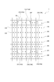
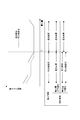
撮像素子7の構成について、図5を参照して説明する。
撮像素子7は、画素が行方向及び列方向にマトリクス状に配列されて成る。それぞれの画素21は、一つの画素に入射する光の一部を遮光する遮光部が設けられた遮光画素21Aと、二つの分割画素によって構成されるPD分割画素21Bのいずれかとされる。 <2. Image sensor configuration>
The configuration of theimage pickup device 7 will be described with reference to FIG.
Theimage pickup device 7 is formed by arranging pixels in a matrix in the row direction and the column direction. Each pixel 21 is either a light-shielding pixel 21A provided with a light-shielding portion that blocks a part of light incident on one pixel, or a PD-divided pixel 21B composed of two divided pixels.
撮像素子7の構成について、図5を参照して説明する。
撮像素子7は、画素が行方向及び列方向にマトリクス状に配列されて成る。それぞれの画素21は、一つの画素に入射する光の一部を遮光する遮光部が設けられた遮光画素21Aと、二つの分割画素によって構成されるPD分割画素21Bのいずれかとされる。 <2. Image sensor configuration>
The configuration of the
The
撮像素子7は、遮光画素21Aが含まれることによりPD遮光方式の位相差信号を出力する第1画素行22Aと、PD分割画素21Bのみで構成されることによりPD分割方式の位相差信号を出力する第2画素行22Bを有している。
The image sensor 7 outputs the PD division type phase difference signal by being composed of only the first pixel row 22A that outputs the PD light shielding method phase difference signal by including the light shielding pixel 21A and the PD division pixel 21B. It has a second pixel row 22B to be used.
第1画素行22Aは、上下方向に離散的に配置され、第1画素行22Aと第1画素行22Aの間には複数行の第2画素行22Bが配置されている。第1画素行22Aは、規則的に配置されていてもよいし、不規則に配置されていてもよい。但し、規則的に配置されている方が、撮像素子7の製造に係る設計コストや製造コストを抑制することができる。
The first pixel row 22A is arranged discretely in the vertical direction, and a plurality of rows of second pixel rows 22B are arranged between the first pixel row 22A and the first pixel row 22A. The first pixel row 22A may be arranged regularly or irregularly. However, if they are arranged regularly, the design cost and the manufacturing cost related to the manufacturing of the image sensor 7 can be suppressed.
第2画素行22Bに含まれる各PD分割画素21Bは、それぞれベイヤー配列のカラーフィルタにより覆われており、カラーフィルタの種類によって赤(R)の分光感度を有するものと緑(G)の分光感度を有するものと青(B)の分光感度を有するものの何れかとされている。
Each PD divided pixel 21B included in the second pixel row 22B is covered with a color filter of a Bayer arrangement, and one having a red (R) spectral sensitivity and a green (G) spectral sensitivity depending on the type of the color filter. It is considered to be either one having the spectral sensitivity of blue (B) or one having the spectral sensitivity of blue (B).
遮光画素21Aの構成について、図6の模式図を参照して説明する。
遮光画素21Aは、PD30と、PD30の前方(被写体側)に配置された遮光部31と、遮光部31の前方に配置されたインナーレンズ32と、インナーレンズ32の前方に配置されたカラーフィルタ(シアン)33と、カラーフィルタ33の前方に配置されたオンチップマイクロレンズ34とを備えている。
なお、遮光画素21Aにインナーレンズ32やカラーフィルタ33が設けられていなくてもよい。 The configuration of the light-shieldingpixel 21A will be described with reference to the schematic diagram of FIG.
The light-shieldingpixel 21A includes a PD 30, a light-shielding portion 31 arranged in front of the PD 30 (subject side), an inner lens 32 arranged in front of the light-shielding portion 31, and a color filter arranged in front of the inner lens 32. It includes a cyan) 33 and an on-chip microlens 34 arranged in front of the color filter 33.
The light-shieldingpixel 21A may not be provided with the inner lens 32 or the color filter 33.
遮光画素21Aは、PD30と、PD30の前方(被写体側)に配置された遮光部31と、遮光部31の前方に配置されたインナーレンズ32と、インナーレンズ32の前方に配置されたカラーフィルタ(シアン)33と、カラーフィルタ33の前方に配置されたオンチップマイクロレンズ34とを備えている。
なお、遮光画素21Aにインナーレンズ32やカラーフィルタ33が設けられていなくてもよい。 The configuration of the light-shielding
The light-shielding
The light-shielding
PD30は、射出瞳EPを通過した光の一部が入射する受光素子であるが、前方に配置された遮光部31により、PD30の受光領域における一部の領域でのみ受光可能とされている。
即ち、遮光部31は、PD30の左半分の領域を覆うように形成されている。遮光部31には、右開口35Rが形成されている。 ThePD 30 is a light receiving element on which a part of the light that has passed through the exit pupil EP is incident, but the light shielding portion 31 arranged in front enables the PD 30 to receive light only in a part of the light receiving region of the PD 30.
That is, the light-shieldingportion 31 is formed so as to cover the left half region of the PD 30. A right opening 35R is formed in the light-shielding portion 31.
即ち、遮光部31は、PD30の左半分の領域を覆うように形成されている。遮光部31には、右開口35Rが形成されている。 The
That is, the light-shielding
インナーレンズ32とオンチップマイクロレンズ34は、射出瞳EPを通過し画素一つ分に入射された光を効率的にPD30に集光するために設けられた光学部品である。
カラーフィルタ33は、例えば、シアン(Cy)の分光感度を有するフィルタとされている。 Theinner lens 32 and the on-chip microlens 34 are optical components provided for efficiently condensing the light that has passed through the exit pupil EP and incident on one pixel on the PD30.
Thecolor filter 33 is, for example, a filter having a spectral sensitivity of cyan (Cy).
カラーフィルタ33は、例えば、シアン(Cy)の分光感度を有するフィルタとされている。 The
The
図6に示されるように、PD30は、射出瞳EPの左半分の領域である左側領域(以降、「左瞳領域EPL」と記載)を通過する光のみを受光するように構成されている。即ち、射出瞳EPの右半分の領域である右側領域(以降、「右瞳領域EPR」と記載)を通過する光は、遮光部31により遮光され、PD30に到達しない。これにより、瞳分割機能を実現する。
As shown in FIG. 6, the PD30 is configured to receive only light passing through the left region (hereinafter referred to as “left pupil region EPL”), which is the left half region of the exit pupil EP. That is, the light passing through the right side region (hereinafter, referred to as “right pupil region EPR”), which is the right half region of the exit pupil EP, is blocked by the light shielding unit 31 and does not reach the PD 30. As a result, the pupil division function is realized.
図6に示すような左瞳領域EPLを通過する光を受光するように構成された遮光画素21Aは、受光面において右側に偏った領域で光を受光することから遮光画素21ARとする。即ち、遮光画素21ARは右開口35Rが形成されている。
また、図6に示す構成に対して鏡面対称とされた構成を有する遮光画素21Aは、右瞳領域EPRを通過する光を受光するように構成された遮光画素21Aであり、この画素は受光面において左側に偏った領域で光を受光することから遮光画素21ALとする。遮光画素21ALが備える遮光部31には、左開口35Lが形成されている。 The light-shieldingpixel 21A configured to receive light passing through the left pupil region EPL as shown in FIG. 6 receives light in a region biased to the right on the light-receiving surface, and thus is referred to as a light-shielding pixel 21AR. That is, the light-shielding pixel 21AR has a right opening 35R.
Further, the light-shieldingpixel 21A having a configuration that is mirror-symmetrical with respect to the configuration shown in FIG. 6 is a light-shielding pixel 21A configured to receive light passing through the right pupil region EPR, and this pixel is a light-receiving surface. Since light is received in a region biased to the left side, the light-shielding pixel 21AL is used. A left opening 35L is formed in the light-shielding portion 31 included in the light-shielding pixel 21AL.
また、図6に示す構成に対して鏡面対称とされた構成を有する遮光画素21Aは、右瞳領域EPRを通過する光を受光するように構成された遮光画素21Aであり、この画素は受光面において左側に偏った領域で光を受光することから遮光画素21ALとする。遮光画素21ALが備える遮光部31には、左開口35Lが形成されている。 The light-shielding
Further, the light-shielding
図5に示すように、遮光画素21ARと遮光画素21ALの距離は例えば画素二つ分の距離とされ、交互に配置されている。
遮光画素21ARから出力される信号と遮光画素21ALから出力される信号は、カメラ信号処理部8(或いはカメラ制御部14)によって一対の位相差信号として扱われる。即ち、遮光画素21ARから出力される信号と遮光画素21ALから出力される信号の位相差を用いて後段のカメラ信号処理部8のデフォーカス量算出部8aはデフォーカス量の算出を行う。 As shown in FIG. 5, the distance between the light-shielding pixels 21AR and the light-shielding pixels 21AL is, for example, the distance of two pixels, and they are arranged alternately.
The signal output from the light-shielding pixel 21AR and the signal output from the light-shielding pixel 21AL are treated as a pair of phase difference signals by the camera signal processing unit 8 (or the camera control unit 14). That is, the defocusamount calculation unit 8a of the camera signal processing unit 8 in the subsequent stage calculates the defocus amount by using the phase difference between the signal output from the light-shielding pixel 21AR and the signal output from the light-shielding pixel 21AL.
遮光画素21ARから出力される信号と遮光画素21ALから出力される信号は、カメラ信号処理部8(或いはカメラ制御部14)によって一対の位相差信号として扱われる。即ち、遮光画素21ARから出力される信号と遮光画素21ALから出力される信号の位相差を用いて後段のカメラ信号処理部8のデフォーカス量算出部8aはデフォーカス量の算出を行う。 As shown in FIG. 5, the distance between the light-shielding pixels 21AR and the light-shielding pixels 21AL is, for example, the distance of two pixels, and they are arranged alternately.
The signal output from the light-shielding pixel 21AR and the signal output from the light-shielding pixel 21AL are treated as a pair of phase difference signals by the camera signal processing unit 8 (or the camera control unit 14). That is, the defocus
続いて、PD分割画素21Bについて説明する。
図7は、撮像素子7における画素21としてのPD分割画素21Bの構成を模式的に示した図である。 Subsequently, thePD division pixel 21B will be described.
FIG. 7 is a diagram schematically showing the configuration of the PD dividedpixel 21B as the pixel 21 in the image sensor 7.
図7は、撮像素子7における画素21としてのPD分割画素21Bの構成を模式的に示した図である。 Subsequently, the
FIG. 7 is a diagram schematically showing the configuration of the PD divided
PD分割画素21Bは、二つの分割画素、即ち、左側の分割画素とされた左PD40Lと右側の分割画素とされた右PD40Rと、その前方に配置された画素境界メタル41と、インナーレンズ32と、カラーフィルタ33と、オンチップマイクロレンズ34とを備えている。カラーフィルタ33は、赤(R)の分光感度を有するカラーフィルタ33Rと、緑(G)の分光感度を有するカラーフィルタ33Gと、青(B)の分光感度を有するカラーフィルタ33Bのいずれかとされる。
なお、PD分割画素21Bにインナーレンズ32等が設けられていなくてもよい。 ThePD division pixel 21B includes two division pixels, that is, a left PD40L as a left division pixel, a right PD40R as a right division pixel, a pixel boundary metal 41 arranged in front of the left PD40L, and an inner lens 32. , A color filter 33 and an on-chip microlens 34. The color filter 33 is one of a color filter 33R having a red (R) spectral sensitivity, a color filter 33G having a green (G) spectral sensitivity, and a color filter 33B having a blue (B) spectral sensitivity. ..
ThePD division pixel 21B may not be provided with the inner lens 32 or the like.
なお、PD分割画素21Bにインナーレンズ32等が設けられていなくてもよい。 The
The
図示するように、左PD40Lは、射出瞳EPの右瞳領域EPRを通過した光を受光する。右PD40Rは、左瞳領域EPLを通過した光を受光する。これにより、瞳分割機能を実現する。
As shown, the left PD40L receives the light that has passed through the right pupil region EPR of the exit pupil EP. The right PD40R receives light that has passed through the left pupil region EPL. As a result, the pupil division function is realized.
As shown, the left PD40L receives the light that has passed through the right pupil region EPR of the exit pupil EP. The right PD40R receives light that has passed through the left pupil region EPL. As a result, the pupil division function is realized.
<3.AF制御>
上述した各画素21を用いて合焦するAF制御方法について説明する。
先ず、遮光画素21AやPD分割画素21Bから出力される位相差信号を用いたAF制御について説明する。 <3. AF control>
An AF control method for focusing using each of the above-mentioned pixels 21 will be described.
First, AF control using the phase difference signal output from the light-shieldingpixel 21A and the PD division pixel 21B will be described.
上述した各画素21を用いて合焦するAF制御方法について説明する。
先ず、遮光画素21AやPD分割画素21Bから出力される位相差信号を用いたAF制御について説明する。 <3. AF control>
An AF control method for focusing using each of the above-mentioned pixels 21 will be described.
First, AF control using the phase difference signal output from the light-shielding
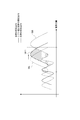
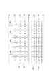
位相差信号について、遮光画素21Aを例に挙げて説明する。
撮像素子7上のある第1画素行22Aについて、遮光画素21Aの位置と出力の関係を示したグラフが図8である。
左開口35Lが形成された遮光画素21ALから出力される信号が実線で示されている。また、右開口35Rが形成された遮光画素21ARから出力される信号が破線で示されている。実線のグラフを左開口画素出力50Lとし、破線のグラフを右開口画素出力50Rとする。 The phase difference signal will be described by taking the light-shieldingpixel 21A as an example.
FIG. 8 is a graph showing the relationship between the position of the light-shieldingpixel 21A and the output of the first pixel row 22A on the image sensor 7.
The signal output from the light-shielding pixel 21AL in which theleft opening 35L is formed is shown by a solid line. Further, the signal output from the light-shielding pixel 21AR in which the right opening 35R is formed is shown by a broken line. The solid line graph is the left aperture pixel output 50L, and the broken line graph is the right aperture pixel output 50R.
撮像素子7上のある第1画素行22Aについて、遮光画素21Aの位置と出力の関係を示したグラフが図8である。
左開口35Lが形成された遮光画素21ALから出力される信号が実線で示されている。また、右開口35Rが形成された遮光画素21ARから出力される信号が破線で示されている。実線のグラフを左開口画素出力50Lとし、破線のグラフを右開口画素出力50Rとする。 The phase difference signal will be described by taking the light-shielding
FIG. 8 is a graph showing the relationship between the position of the light-shielding
The signal output from the light-shielding pixel 21AL in which the
左開口画素出力50Lの波形と右開口画素出力50Rの波形の差分積分値を図9に斜線部で示す。
次に、左開口画素出力50Lの波形をグラフの右方向に一定距離シフトさせたものを波形50L1として図10に示す。図10の斜線部は波形50L1と右開口画素出力50Rの差分積分値を示している。 The difference integrated value between the waveform of the leftaperture pixel output 50L and the waveform of the right aperture pixel output 50R is shown by shaded areas in FIG.
Next, the waveform of the leftaperture pixel output 50L shifted to the right of the graph by a certain distance is shown in FIG. 10 as the waveform 50L1. The shaded area in FIG. 10 shows the difference integral value between the waveform 50L1 and the right aperture pixel output 50R.
次に、左開口画素出力50Lの波形をグラフの右方向に一定距離シフトさせたものを波形50L1として図10に示す。図10の斜線部は波形50L1と右開口画素出力50Rの差分積分値を示している。 The difference integrated value between the waveform of the left
Next, the waveform of the left
波形50L1を更に一定距離右方向にシフトさせたものを波形50L2として図11に示す。図11の斜線部は波形50L2と右開口画素出力50Rの差分積分値を示している。
The waveform 50L1 further shifted to the right by a certain distance is shown in FIG. 11 as the waveform 50L2. The shaded area in FIG. 11 shows the difference integral value between the waveform 50L2 and the right aperture pixel output 50R.
波形50L2を更に一定距離右方向にシフトさせたものを波形50L3として図12に示す。図12の斜線部は波形50L3と右開口画素出力50Rの差分積分値を示している。
The waveform 50L2 further shifted to the right by a certain distance is shown in FIG. 12 as the waveform 50L3. The shaded area in FIG. 12 shows the difference integral value between the waveform 50L3 and the right aperture pixel output 50R.
図9,図10,図11及び図12に斜線部で示した差分積分値をグラフ化したものを図13に示す。
図示するように、シフト量を増やすほど差分積分値が小さくなり、所定のシフト量を超えるとシフト量を増やすほど差分積分値が再び大きくなる。
差分積分値が最も小さくなるシフト量が位相差である。即ち、遮光画素21ALと遮光画素21ARの出力が位相差分シフトされ左開口画素出力50Lと右開口画素出力50Rの波形が略重なるようにフォーカスレンズを動かすことで適切なAF制御を行うことができる。 FIG. 13 shows a graph of the differential integral values shown in the shaded areas in FIGS. 9, 10, 11 and 12.
As shown in the figure, the difference integral value becomes smaller as the shift amount is increased, and the difference integral value becomes larger again as the shift amount is increased when the predetermined shift amount is exceeded.
The shift amount with the smallest difference integral value is the phase difference. That is, appropriate AF control can be performed by moving the focus lens so that the outputs of the light-shielding pixel 21AL and the light-shielding pixel 21AR are phase-difference-shifted so that the waveforms of the leftaperture pixel output 50L and the right aperture pixel output 50R substantially overlap.
図示するように、シフト量を増やすほど差分積分値が小さくなり、所定のシフト量を超えるとシフト量を増やすほど差分積分値が再び大きくなる。
差分積分値が最も小さくなるシフト量が位相差である。即ち、遮光画素21ALと遮光画素21ARの出力が位相差分シフトされ左開口画素出力50Lと右開口画素出力50Rの波形が略重なるようにフォーカスレンズを動かすことで適切なAF制御を行うことができる。 FIG. 13 shows a graph of the differential integral values shown in the shaded areas in FIGS. 9, 10, 11 and 12.
As shown in the figure, the difference integral value becomes smaller as the shift amount is increased, and the difference integral value becomes larger again as the shift amount is increased when the predetermined shift amount is exceeded.
The shift amount with the smallest difference integral value is the phase difference. That is, appropriate AF control can be performed by moving the focus lens so that the outputs of the light-shielding pixel 21AL and the light-shielding pixel 21AR are phase-difference-shifted so that the waveforms of the left
なお、左開口画素出力50Lの波形をシフトする方向によって所謂前ピンと後ピンを区別することができる。即ち、図9の状態においては、左開口画素出力50Lの波形を右方向へシフトさせることにより差分積分値を最小にすることができる。この状態は、所謂前ピンの状態とされる。
一方、左開口画素出力50Lの波形を左方向へシフトさせることにより差分積分値を最小値にすることができる場合は、所謂後ピンの状態とされる。 The so-called front pin and rear pin can be distinguished by the direction in which the waveform of the leftaperture pixel output 50L is shifted. That is, in the state of FIG. 9, the difference integrated value can be minimized by shifting the waveform of the left aperture pixel output 50L to the right. This state is the so-called front pin state.
On the other hand, when the difference integrated value can be minimized by shifting the waveform of the leftaperture pixel output 50L to the left, it is in the so-called rear pin state.
一方、左開口画素出力50Lの波形を左方向へシフトさせることにより差分積分値を最小値にすることができる場合は、所謂後ピンの状態とされる。 The so-called front pin and rear pin can be distinguished by the direction in which the waveform of the left
On the other hand, when the difference integrated value can be minimized by shifting the waveform of the left
なお、詳細には、遮光画素21ALと遮光画素21ARは撮像素子7上で画素二つ分離れていることから、左開口画素出力50Lと右開口画素出力50Rの波形が画素二つ分ずれた状態となるようにフォーカスレンズを動かすことで最適な合焦状態を作り出すことができる。
Specifically, since the light-shielding pixel 21AL and the light-shielding pixel 21AR are separated into two pixels on the image sensor 7, the waveforms of the left aperture pixel output 50L and the right aperture pixel output 50R are deviated by two pixels. By moving the focus lens so that it becomes, the optimum focusing state can be created.
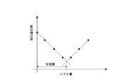
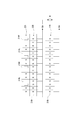
図14にシフト量とデフォーカス量の関係を示す。シフト量とは、図13に示す差分積分値が元も小さくなるシフト量のことであり、位相差と換言することができる。シフト量とデフォーカス量の関係は1次関数で表される。シフト量が大きいほどデフォーカス量は大きくされ、シフト量が大きい状態は、即ちピントが合っていない状態である。シフト量からデフォーカス量を算出することができる。
FIG. 14 shows the relationship between the shift amount and the defocus amount. The shift amount is a shift amount in which the difference integral value shown in FIG. 13 is originally small, and can be rephrased as a phase difference. The relationship between the shift amount and the defocus amount is expressed by a linear function. The larger the shift amount, the larger the defocus amount, and the larger the shift amount, that is, the out-of-focus state. The defocus amount can be calculated from the shift amount.
ここまでは遮光画素21Aから出力される位相差信号に基づくAF制御について説明したが、PD分割画素21Bから出力される位相差信号に基づくAF制御についても同様に行うことができる。
Up to this point, the AF control based on the phase difference signal output from the light-shielding pixel 21A has been described, but the AF control based on the phase difference signal output from the PD division pixel 21B can also be performed in the same manner.
具体的には、PD分割画素21Bの左PD40Lから出力される信号(各図における左開口画素出力50Lに相当)の波形と右PD40Rから出力される信号(各図における右開口画素出力50Rに相当)の波形を比較し、それらの波形を略一致させるためのシフト量を算出することでデフォーカス量を求めることができる。
Specifically, the waveform of the signal output from the left PD40L of the PD divided pixel 21B (corresponding to the left opening pixel output 50L in each figure) and the signal output from the right PD40R (corresponding to the right opening pixel output 50R in each figure). ), And the defocus amount can be obtained by calculating the shift amount for substantially matching the waveforms.
なお、遮光画素21AやPD分割画素21Bから出力される信号から信頼度の高いデフォーカス量が算出できなかった場合には、コントラスト方式を用いてデフォーカス量を算出することが考えられる。
例えば、カメラ信号処理部8内で生成した輝度信号を元にコントラストを検出し、フォーカス制御を行う。
なお、ここで説明したコントラスト方式は一例であり、その他にも公知である多種多様な方法を用いてコントラスト方式によるデフォーカス量の算出を行うことができる。
If a highly reliable defocus amount cannot be calculated from the signals output from the light-shieldingpixel 21A or the PD division pixel 21B, it is conceivable to calculate the defocus amount using the contrast method.
For example, the contrast is detected based on the luminance signal generated in the camerasignal processing unit 8 and the focus is controlled.
The contrast method described here is an example, and the defocus amount can be calculated by the contrast method using a wide variety of other known methods.
例えば、カメラ信号処理部8内で生成した輝度信号を元にコントラストを検出し、フォーカス制御を行う。
なお、ここで説明したコントラスト方式は一例であり、その他にも公知である多種多様な方法を用いてコントラスト方式によるデフォーカス量の算出を行うことができる。
If a highly reliable defocus amount cannot be calculated from the signals output from the light-shielding
For example, the contrast is detected based on the luminance signal generated in the camera
The contrast method described here is an example, and the defocus amount can be calculated by the contrast method using a wide variety of other known methods.
<4.軸上領域と軸外領域>
撮像素子7は、中央付近の領域とそれ以外の領域で画素21の構成が異なっていてもよい。具体的に、撮像素子7における中央付近の領域を軸上領域ArCとし、それ以外の領域を軸外領域ArMとして説明する。
なお、図15は、軸上領域ArCと軸外領域ArMの一例であるが、軸上領域ArCが略円形状の領域とされていてもよいし、その他の形状とされてもよい。また、各画素が軸上領域ArCと軸外領域ArMの何れに属するかについては、予めメモリ部15に記憶されている。従って、カメラ制御部14は、メモリ部15を参照することにより画素や領域が軸上領域ArCと軸外領域ArMの何れに属するか判断することができる。 <4. On-axis and off-axis areas>
Theimage sensor 7 may have different pixel 21 configurations in a region near the center and a region other than the center. Specifically, the region near the center of the image sensor 7 will be referred to as an on-axis region ArC, and the other regions will be referred to as an off-axis region ArM.
Although FIG. 15 is an example of the on-axis region ArC and the off-axis region ArM, the on-axis region ArC may be a substantially circular region or may have other shapes. Further, which of the on-axis region ArC and the off-axis region ArM each pixel belongs to is stored in advance in thememory unit 15. Therefore, the camera control unit 14 can determine whether the pixel or region belongs to the on-axis region ArC or the off-axis region Arm by referring to the memory unit 15.
撮像素子7は、中央付近の領域とそれ以外の領域で画素21の構成が異なっていてもよい。具体的に、撮像素子7における中央付近の領域を軸上領域ArCとし、それ以外の領域を軸外領域ArMとして説明する。
なお、図15は、軸上領域ArCと軸外領域ArMの一例であるが、軸上領域ArCが略円形状の領域とされていてもよいし、その他の形状とされてもよい。また、各画素が軸上領域ArCと軸外領域ArMの何れに属するかについては、予めメモリ部15に記憶されている。従って、カメラ制御部14は、メモリ部15を参照することにより画素や領域が軸上領域ArCと軸外領域ArMの何れに属するか判断することができる。 <4. On-axis and off-axis areas>
The
Although FIG. 15 is an example of the on-axis region ArC and the off-axis region ArM, the on-axis region ArC may be a substantially circular region or may have other shapes. Further, which of the on-axis region ArC and the off-axis region ArM each pixel belongs to is stored in advance in the
軸上領域ArCに配置された画素21Cは、図16に示すように、受光面に対して略直交する方向から入射した光を受光する。一方、軸外領域ArMに配置された画素21Mは、図示するように、受光面に対して斜め方向から入射する光を受光する。
As shown in FIG. 16, the pixel 21C arranged in the on-axis region ArC receives light incident from a direction substantially orthogonal to the light receiving surface. On the other hand, as shown in the figure, the pixel 21M arranged in the off-axis region ArM receives light incident on the light receiving surface from an oblique direction.
撮像素子7の各画素21は、中央部分から離隔する距離に位置するほど各部が中央部側にオフセットされた構成とされている。
図6に示す遮光画素21ARは、例えば、軸上領域ArCの略中央に配置された画素21Cの一例である。
軸外領域ArMに配置された画素21Mとしての遮光画素21ARについて、図17を参照して説明する。 Each pixel 21 of theimage sensor 7 has a configuration in which each portion is offset toward the central portion so that the pixel 21 is located at a distance away from the central portion.
The light-shielding pixel 21AR shown in FIG. 6 is, for example, an example of thepixel 21C arranged substantially in the center of the axial region ArC.
The light-shielding pixel 21AR as thepixel 21M arranged in the off-axis region ArM will be described with reference to FIG.
図6に示す遮光画素21ARは、例えば、軸上領域ArCの略中央に配置された画素21Cの一例である。
軸外領域ArMに配置された画素21Mとしての遮光画素21ARについて、図17を参照して説明する。 Each pixel 21 of the
The light-shielding pixel 21AR shown in FIG. 6 is, for example, an example of the
The light-shielding pixel 21AR as the
図示するように、PD30及び遮光部31に対してインナーレンズ32及びカラーフィルタ33が射出瞳EP側にオフセットされて配置されている。また、インナーレンズ32及びカラーフィルタ33に対してオンチップマイクロレンズ34が射出瞳EP側にオフセットされて配置されている。
このような構成により、射出瞳EPから斜めに入射する光を効率よくPD30に入射させることができる。 As shown in the figure, theinner lens 32 and the color filter 33 are offset from the PD 30 and the light-shielding portion 31 toward the exit pupil EP. Further, the on-chip microlens 34 is offset to the exit pupil EP side with respect to the inner lens 32 and the color filter 33.
With such a configuration, light incident obliquely from the exit pupil EP can be efficiently incident on thePD 30.
このような構成により、射出瞳EPから斜めに入射する光を効率よくPD30に入射させることができる。 As shown in the figure, the
With such a configuration, light incident obliquely from the exit pupil EP can be efficiently incident on the
次に、軸外領域ArMに配置された画素21MとしてのPD分割画素21Bについて、図18に示す。
図示するように、左PD40L及び右PD40Rの前方には画素境界メタル41が配置され、画素境界メタル41の前方には画素境界メタル41に対してインナーレンズ32及びカラーフィルタ33が射出瞳EP側にオフセットされて配置されている。また、インナーレンズ32及びカラーフィルタ33に対してオンチップマイクロレンズ34が射出瞳EP側にオフセットされて配置されている。 Next, thePD division pixel 21B as the pixel 21M arranged in the off-axis region ArM is shown in FIG.
As shown in the figure, thepixel boundary metal 41 is arranged in front of the left PD40L and the right PD40R, and the inner lens 32 and the color filter 33 are on the ejection pupil EP side with respect to the pixel boundary metal 41 in front of the pixel boundary metal 41. It is arranged offset. Further, the on-chip microlens 34 is offset to the exit pupil EP side with respect to the inner lens 32 and the color filter 33.
図示するように、左PD40L及び右PD40Rの前方には画素境界メタル41が配置され、画素境界メタル41の前方には画素境界メタル41に対してインナーレンズ32及びカラーフィルタ33が射出瞳EP側にオフセットされて配置されている。また、インナーレンズ32及びカラーフィルタ33に対してオンチップマイクロレンズ34が射出瞳EP側にオフセットされて配置されている。 Next, the
As shown in the figure, the
画素21が遮光画素21AであるかPD分割画素21Bであるかによらず、インナーレンズ32やカラーフィルタ33などの各部のオフセット量は画素21の配置位置に応じて決定される。これにより、撮像素子7への各部の形成が容易となる。
また、各部がオフセットされて形成されることにより、射出瞳EPから斜めに入射する光を効率よく左PD40L及び右PD40Rに入射させることができると共に、左瞳領域EPLを通過した光が右PD40Rに入射され右瞳領域EPRを通過した光が左PD40Lに入射される。即ち、瞳分割機能が実現される。
Regardless of whether the pixel 21 is the light-shieldingpixel 21A or the PD division pixel 21B, the offset amount of each part such as the inner lens 32 and the color filter 33 is determined according to the arrangement position of the pixel 21. This facilitates the formation of each part on the image sensor 7.
Further, since each part is formed by being offset, the light obliquely incident from the exit pupil EP can be efficiently incident on the left PD40L and the right PD40R, and the light passing through the left pupil region EPL can be efficiently incident on the right PD40R. Light that has been incident and has passed through the right pupil region EPR is incident on the left PD40L. That is, the pupil division function is realized.
また、各部がオフセットされて形成されることにより、射出瞳EPから斜めに入射する光を効率よく左PD40L及び右PD40Rに入射させることができると共に、左瞳領域EPLを通過した光が右PD40Rに入射され右瞳領域EPRを通過した光が左PD40Lに入射される。即ち、瞳分割機能が実現される。
Regardless of whether the pixel 21 is the light-shielding
Further, since each part is formed by being offset, the light obliquely incident from the exit pupil EP can be efficiently incident on the left PD40L and the right PD40R, and the light passing through the left pupil region EPL can be efficiently incident on the right PD40R. Light that has been incident and has passed through the right pupil region EPR is incident on the left PD40L. That is, the pupil division function is realized.
<5.瞳距離と画素構成>
画素21に入射する光の角度は、射出瞳と撮像素子7の距離にも影響される。射出瞳と撮像素子7の距離が近いほど、画素21への入射角は大きくなる。入射角度が変化すると、左瞳領域EPLを通過した光を受光するPD30の受光領域が変化する。
例えば、図17は、射出瞳EPの瞳距離が所定の距離とされている場合の構成を示したものであり、右開口35RがPD30の表面積の半分よりも大きくされている。 <5. Eye distance and pixel composition>
The angle of light incident on the pixel 21 is also affected by the distance between the exit pupil and theimage sensor 7. The closer the exit pupil and the image sensor 7 are, the larger the angle of incidence on the pixel 21. When the incident angle changes, the light receiving region of the PD 30 that receives the light that has passed through the left pupil region EPL changes.
For example, FIG. 17 shows a configuration when the pupil distance of the exit pupil EP is a predetermined distance, and theright opening 35R is made larger than half the surface area of the PD30.
画素21に入射する光の角度は、射出瞳と撮像素子7の距離にも影響される。射出瞳と撮像素子7の距離が近いほど、画素21への入射角は大きくなる。入射角度が変化すると、左瞳領域EPLを通過した光を受光するPD30の受光領域が変化する。
例えば、図17は、射出瞳EPの瞳距離が所定の距離とされている場合の構成を示したものであり、右開口35RがPD30の表面積の半分よりも大きくされている。 <5. Eye distance and pixel composition>
The angle of light incident on the pixel 21 is also affected by the distance between the exit pupil and the
For example, FIG. 17 shows a configuration when the pupil distance of the exit pupil EP is a predetermined distance, and the
レンズ鏡筒3が交換式レンズである場合には、光学系16の種類によって射出瞳EPの瞳距離が変化する。射出瞳EPが所定の距離よりも近い場合には、図17に示す遮光画素21ARでは、射出瞳EPの左瞳領域EPLを通過した光だけでなく右瞳領域EPRを通過した光も受光してしまう。
When the lens barrel 3 is an interchangeable lens, the pupil distance of the exit pupil EP changes depending on the type of the optical system 16. When the exit pupil EP is closer than a predetermined distance, the light-shielding pixel 21AR shown in FIG. 17 receives not only the light that has passed through the left pupil region EPL of the exit pupil EP but also the light that has passed through the right pupil region EPR. It ends up.
そこで、本実施の形態においては、射出瞳EPの瞳距離に応じた複数種類の遮光画素21AR及び遮光画素21ALを備えている。
Therefore, in the present embodiment, a plurality of types of light-shielding pixels 21AR and light-shielding pixels 21AL are provided according to the pupil distance of the exit pupil EP.
具体的に、図17及び図19を参照して説明する。図17は、射出瞳EPの瞳距離が所定の距離とされた光学系16に対して、左瞳領域EPLを通過した光がPD30に受光されるように遮光部31の右開口35Rを形成したものである。
Specifically, it will be described with reference to FIGS. 17 and 19. In FIG. 17, the right opening 35R of the light-shielding portion 31 is formed so that the light passing through the left pupil region EPL is received by the PD 30 with respect to the optical system 16 in which the pupil distance of the exit pupil EP is set to a predetermined distance. It is a thing.
一方、図19は、射出瞳EPの瞳距離が所定の距離よりも短い光学系16に対して、左瞳領域EPLを通過した光がPD30に受光されるように遮光部31の右開口35Rを形成したものである。
両図から理解されるように、瞳距離が短い光学系16における左瞳領域EPLを通過した光をPD30で受光するためには、より斜めに入射する入射光に対応する必要がある。
即ち、図19に示す構成においては、右開口35Rが狭くされると共に、右開口35Rにおける射出瞳EP側の開口端がより射出瞳EPから離隔された位置とされている。
このような構成を採ることにより、遮光画素21AR及び遮光画素21ALを射出瞳EPの瞳距離が短い場合に対応させることができ、瞳分割機能を機能させることができる。 On the other hand, FIG. 19 shows theright opening 35R of the light-shielding portion 31 so that the light passing through the left pupil region EPL is received by the PD 30 with respect to the optical system 16 in which the pupil distance of the exit pupil EP is shorter than a predetermined distance. It is formed.
As can be understood from both figures, in order for the PD30 to receive the light that has passed through the left pupil region EPL in theoptical system 16 having a short pupil distance, it is necessary to correspond to the incident light that is incident more obliquely.
That is, in the configuration shown in FIG. 19, theright opening 35R is narrowed, and the opening end of the right opening 35R on the exit pupil EP side is located at a position further separated from the exit pupil EP.
By adopting such a configuration, the light-shielding pixel 21AR and the light-shielding pixel 21AL can be made to correspond to the case where the pupil distance of the exit pupil EP is short, and the pupil division function can be made to function.
両図から理解されるように、瞳距離が短い光学系16における左瞳領域EPLを通過した光をPD30で受光するためには、より斜めに入射する入射光に対応する必要がある。
即ち、図19に示す構成においては、右開口35Rが狭くされると共に、右開口35Rにおける射出瞳EP側の開口端がより射出瞳EPから離隔された位置とされている。
このような構成を採ることにより、遮光画素21AR及び遮光画素21ALを射出瞳EPの瞳距離が短い場合に対応させることができ、瞳分割機能を機能させることができる。 On the other hand, FIG. 19 shows the
As can be understood from both figures, in order for the PD30 to receive the light that has passed through the left pupil region EPL in the
That is, in the configuration shown in FIG. 19, the
By adopting such a configuration, the light-shielding pixel 21AR and the light-shielding pixel 21AL can be made to correspond to the case where the pupil distance of the exit pupil EP is short, and the pupil division function can be made to function.
尚、図17及び図19に示す遮光画素21ARは、インナーレンズ32、カラーフィルタ33、オンチップマイクロレンズ34のオフセット量は同じとされている。
即ち、遮光部31の右開口35Rの形状のみが異なる。 In the light-shielding pixels 21AR shown in FIGS. 17 and 19, the offset amounts of theinner lens 32, the color filter 33, and the on-chip microlens 34 are the same.
That is, only the shape of theright opening 35R of the light-shielding portion 31 is different.
即ち、遮光部31の右開口35Rの形状のみが異なる。 In the light-shielding pixels 21AR shown in FIGS. 17 and 19, the offset amounts of the
That is, only the shape of the
図17に示す遮光画素21ARや遮光画素21ALと、図19に示す遮光画素21ARや遮光画素21ALは、撮像素子7上に複数設けられている。
本例では、瞳距離に応じた8種類の遮光画素21AR及び遮光画素21ALが撮像素子7上に配置されている。即ち、8種類の遮光画素21ARや遮光画素21ALにおいては、右開口35Rや左開口35Lの開口面積が8段階に亘って異なるものが設けられている。
以下の説明においては、8種類の瞳距離を瞳距離が近い方から順に瞳距離S0~瞳距離S7とする。
そして、瞳距離S0に対応する遮光画素21AR及び遮光画素21ALを遮光画素RS0、LS0とする。同様に、瞳距離S1に対応する遮光画素21AR及び遮光画素21ALを遮光画素RS1、LS1、瞳距離S2に対応する遮光画素21AR及び遮光画素21ALを遮光画素RS2、LS2、瞳距離S3に対応する遮光画素21AR及び遮光画素21ALを遮光画素RS3、LS3、瞳距離S4に対応する遮光画素21AR及び遮光画素21ALを遮光画素RS4、LS4、瞳距離S5に対応する遮光画素21AR及び遮光画素21ALを遮光画素RS5、LS5、瞳距離S6に対応する遮光画素21AR及び遮光画素21ALを遮光画素RS6、LS6、瞳距離S7に対応する遮光画素21AR及び遮光画素21ALを遮光画素RS7、LS7とする。 A plurality of light-shielding pixels 21AR and light-shielding pixels 21AL shown in FIG. 17 and a plurality of light-shielding pixels 21AR and light-shielding pixels 21AL shown in FIG. 19 are provided on theimage sensor 7.
In this example, eight types of light-shielding pixels 21AR and light-shielding pixels 21AL according to the pupil distance are arranged on theimage sensor 7. That is, in the eight types of light-shielding pixels 21AR and light-shielding pixels 21AL, the right opening 35R and the left opening 35L are provided with different opening areas in eight stages.
In the following description, the eight types of pupil distances are defined as the pupil distance S0 to the pupil distance S7 in order from the one with the closest pupil distance.
Then, the light-shielding pixels 21AR and the light-shielding pixels 21AL corresponding to the pupil distance S0 are designated as light-shielding pixels RS0 and LS0. Similarly, the light-shielding pixels 21AR and the light-shielding pixels 21AL corresponding to the pupil distance S1 are the light-shielding pixels RS1, LS1, and the light-shielding pixels 21AR and the light-shielding pixels 21AL corresponding to the pupil distance S2 are light-shielded pixels RS2, LS2, and the light-shielding pixels 21AL. Pixels 21AR and shading pixels 21AL correspond to shading pixels RS3, LS3, pupil distance S4. Shading pixels 21AR and shading pixels 21AL correspond to shading pixels RS4, LS4, pupil distance S5. , LS5, the light-shielding pixel 21AR and the light-shielding pixel 21AL corresponding to the pupil distance S6 are the light-shielding pixels RS6, LS6, and the light-shielding pixel 21AR and the light-shielding pixel 21AL corresponding to the pupil distance S7 are the light-shielding pixels RS7 and LS7.
本例では、瞳距離に応じた8種類の遮光画素21AR及び遮光画素21ALが撮像素子7上に配置されている。即ち、8種類の遮光画素21ARや遮光画素21ALにおいては、右開口35Rや左開口35Lの開口面積が8段階に亘って異なるものが設けられている。
以下の説明においては、8種類の瞳距離を瞳距離が近い方から順に瞳距離S0~瞳距離S7とする。
そして、瞳距離S0に対応する遮光画素21AR及び遮光画素21ALを遮光画素RS0、LS0とする。同様に、瞳距離S1に対応する遮光画素21AR及び遮光画素21ALを遮光画素RS1、LS1、瞳距離S2に対応する遮光画素21AR及び遮光画素21ALを遮光画素RS2、LS2、瞳距離S3に対応する遮光画素21AR及び遮光画素21ALを遮光画素RS3、LS3、瞳距離S4に対応する遮光画素21AR及び遮光画素21ALを遮光画素RS4、LS4、瞳距離S5に対応する遮光画素21AR及び遮光画素21ALを遮光画素RS5、LS5、瞳距離S6に対応する遮光画素21AR及び遮光画素21ALを遮光画素RS6、LS6、瞳距離S7に対応する遮光画素21AR及び遮光画素21ALを遮光画素RS7、LS7とする。 A plurality of light-shielding pixels 21AR and light-shielding pixels 21AL shown in FIG. 17 and a plurality of light-shielding pixels 21AR and light-shielding pixels 21AL shown in FIG. 19 are provided on the
In this example, eight types of light-shielding pixels 21AR and light-shielding pixels 21AL according to the pupil distance are arranged on the
In the following description, the eight types of pupil distances are defined as the pupil distance S0 to the pupil distance S7 in order from the one with the closest pupil distance.
Then, the light-shielding pixels 21AR and the light-shielding pixels 21AL corresponding to the pupil distance S0 are designated as light-shielding pixels RS0 and LS0. Similarly, the light-shielding pixels 21AR and the light-shielding pixels 21AL corresponding to the pupil distance S1 are the light-shielding pixels RS1, LS1, and the light-shielding pixels 21AR and the light-shielding pixels 21AL corresponding to the pupil distance S2 are light-shielded pixels RS2, LS2, and the light-shielding pixels 21AL. Pixels 21AR and shading pixels 21AL correspond to shading pixels RS3, LS3, pupil distance S4. Shading pixels 21AR and shading pixels 21AL correspond to shading pixels RS4, LS4, pupil distance S5. , LS5, the light-shielding pixel 21AR and the light-shielding pixel 21AL corresponding to the pupil distance S6 are the light-shielding pixels RS6, LS6, and the light-shielding pixel 21AR and the light-shielding pixel 21AL corresponding to the pupil distance S7 are the light-shielding pixels RS7 and LS7.
また、遮光画素RS0,LS0が配置された第1画素行を第1画素行22A0とし、遮光画素RS1,LS1が配置された第1画素行を第1画素行22A1とし、遮光画素RS2,LS2が配置された第1画素行を第1画素行22A2とし、遮光画素RS3,LS3が配置された第1画素行を第1画素行22A3とし、遮光画素RS4,LS4が配置された第1画素行を第1画素行22A4とし、遮光画素RS5,LS5が配置された第1画素行を第1画素行22A5とし、遮光画素RS6,LS6が配置された第1画素行を第1画素行22A6とし、遮光画素RS7,LS7が配置された第1画素行を第1画素行22A7とする。
Further, the first pixel row in which the light-shielding pixels RS0 and LS0 are arranged is referred to as the first pixel row 22A0, the first pixel row in which the light-shielding pixels RS1 and LS1 are arranged is referred to as the first pixel row 22A1, and the light-shielding pixels RS2 and LS2 are designated. The arranged first pixel row is referred to as the first pixel row 22A2, the first pixel row in which the light-shielding pixels RS3 and LS3 are arranged is referred to as the first pixel row 22A3, and the first pixel row in which the light-shielding pixels RS4 and LS4 are arranged is designated as the first pixel row. The first pixel row is 22A4, the first pixel row in which the light-shielding pixels RS5 and LS5 are arranged is the first pixel row 22A5, and the first pixel row in which the light-shielding pixels RS6 and LS6 are arranged is the first pixel row 22A6. The first pixel row in which the pixels RS7 and LS7 are arranged is referred to as the first pixel row 22A7.
図20に第1画素行22A0から第1画素行22A7の配置態様の一例について示す。
図20は、撮像素子7の一部を拡大して示すものである。図示するように、遮光画素RS0,LS0が配置された第1画素行22A0から遮光画素RS7,LS7が配置された第1画素行22A7が上下に一定距離離隔されて配置されると共に、第1画素行22A0から第1画素行22A7の各画素行が上下方向に周期的に配置されている。 FIG. 20 shows an example of the arrangement mode of the first pixel row 22A0 to the first pixel row 22A7.
FIG. 20 is an enlarged view of a part of theimage sensor 7. As shown in the figure, the first pixel row 22A0 in which the light-shielding pixels RS0 and LS0 are arranged is arranged vertically at a certain distance from the first pixel row 22A7 in which the light-shielding pixels RS7 and LS7 are arranged, and the first pixel is arranged. Each pixel row from the row 22A0 to the first pixel row 22A7 is periodically arranged in the vertical direction.
図20は、撮像素子7の一部を拡大して示すものである。図示するように、遮光画素RS0,LS0が配置された第1画素行22A0から遮光画素RS7,LS7が配置された第1画素行22A7が上下に一定距離離隔されて配置されると共に、第1画素行22A0から第1画素行22A7の各画素行が上下方向に周期的に配置されている。 FIG. 20 shows an example of the arrangement mode of the first pixel row 22A0 to the first pixel row 22A7.
FIG. 20 is an enlarged view of a part of the
第1画素行22A0から第1画素行22A7の各画素行は、デフォーカス量を算出するための位相差信号SG0から位相差信号SG7を出力するが、後段のデフォーカス量算出部8aは、射出瞳EPの瞳距離に応じて適切な位相差信号SGを選択してデフォーカス量の算出を行う。例えば、射出瞳EPの瞳距離が瞳距離S3である場合は、第1画素行22A3から出力される位相差信号SG3を用いてデフォーカス量の算出を行う。
Each of the pixel rows of the first pixel row 22A0 to the first pixel row 22A7 outputs the phase difference signal SG7 from the phase difference signal SG0 for calculating the defocus amount, but the defocus amount calculation unit 8a in the subsequent stage emits. The defocus amount is calculated by selecting an appropriate phase difference signal SG according to the pupil distance of the pupil EP. For example, when the pupil distance of the exit pupil EP is the pupil distance S3, the defocus amount is calculated using the phase difference signal SG3 output from the first pixel row 22A3.
次に、軸外領域ArMに配置された画素21MとしてのPD分割画素21Bについて、瞳距離との関係を説明する。軸外領域ArMに配置されたPD分割画素21Bにおいて、左瞳領域EPLを通過した光のみが右PD40Rに入射され、且つ、右瞳領域EPRを通過した光のみが左PD40Lに入射される条件は、撮像素子7の設計通りの瞳距離を有した光学系16を用いた場合のみである。この場合は、射出瞳EPの中心を通った光が二つの分割画素の境目に入射されるため、瞳分割機能が適切に働くこととなる。
Next, the relationship between the PD division pixel 21B as the pixel 21M arranged in the off-axis region ArM and the pupil distance will be described. In the PD split pixel 21B arranged in the off-axis region Arm, only the light that has passed through the left pupil region EPL is incident on the right PD40R, and only the light that has passed through the right pupil region EPR is incident on the left PD40L. This is only the case where the optical system 16 having the pupil distance as designed by the image sensor 7 is used. In this case, since the light passing through the center of the exit pupil EP is incident on the boundary between the two divided pixels, the pupil division function works properly.
ところが、撮像素子7の設計通りの瞳距離とは異なる瞳距離を有した光学系16を用いた場合、射出瞳EPの中心を通った光はいずれかの分割画素に偏って入射される。この状態で瞳分割機能を適切に機能させるためには、二つの分割画素の大きさの割合を変えることにより射出瞳EPの中心を通った光が両分割画素の境目に入射されるようにすることが考えられる。即ち、複数種類の遮光画素21Aを撮像素子7上に設けたように、瞳距離S0から瞳距離S7のそれぞれに対応したPD分割画素21Bを撮像素子7に設ける必要がある。
However, when the optical system 16 having a pupil distance different from the pupil distance designed by the image sensor 7 is used, the light passing through the center of the exit pupil EP is biased into one of the divided pixels. In order for the pupil division function to function properly in this state, the light passing through the center of the exit pupil EP is incident on the boundary between the two division pixels by changing the ratio of the sizes of the two division pixels. Can be considered. That is, it is necessary to provide the image sensor 7 with PD division pixels 21B corresponding to each of the pupil distance S0 to the pupil distance S7, just as a plurality of types of light-shielding pixels 21A are provided on the image sensor 7.
しかし、PD分割画素21Bごとに二つの分割画素の面積比を変えることは技術的な困難性が大きいと共に、製造コストの増大を招来してしまう。
そこで、本実施の形態における撮像装置1においては、特定の瞳距離(例えば瞳距離S3)に応じたPD分割画素21Bのみを撮像素子7上に設けることとする。
なお、ここでは、遮光画素21AR及び遮光画素21ALが瞳距離に応じて8種類設けられた例を説明したが、それ以外であってもよい。即ち、遮光画素21AR及び遮光画素21ALが瞳距離によらず1種類のみ設けられていてもよいし、瞳距離に応じて複数種類設けられていてもよい。
However, changing the area ratio of the two divided pixels for each of the PD dividedpixels 21B is technically difficult and causes an increase in manufacturing cost.
Therefore, in theimage pickup device 1 according to the present embodiment, only the PD division pixels 21B corresponding to a specific pupil distance (for example, the pupil distance S3) are provided on the image pickup element 7.
Here, an example in which eight types of light-shielding pixels 21AR and light-shielding pixels 21AL are provided according to the pupil distance has been described, but other than that may be used. That is, only one type of light-shielding pixel 21AR and light-shielding pixel 21AL may be provided regardless of the pupil distance, or a plurality of types may be provided depending on the pupil distance.
そこで、本実施の形態における撮像装置1においては、特定の瞳距離(例えば瞳距離S3)に応じたPD分割画素21Bのみを撮像素子7上に設けることとする。
なお、ここでは、遮光画素21AR及び遮光画素21ALが瞳距離に応じて8種類設けられた例を説明したが、それ以外であってもよい。即ち、遮光画素21AR及び遮光画素21ALが瞳距離によらず1種類のみ設けられていてもよいし、瞳距離に応じて複数種類設けられていてもよい。
However, changing the area ratio of the two divided pixels for each of the PD divided
Therefore, in the
Here, an example in which eight types of light-shielding pixels 21AR and light-shielding pixels 21AL are provided according to the pupil distance has been described, but other than that may be used. That is, only one type of light-shielding pixel 21AR and light-shielding pixel 21AL may be provided regardless of the pupil distance, or a plurality of types may be provided depending on the pupil distance.
<6.位相差画素の違いによるAF制御の違い>
撮像素子7から出力される位相差信号に基づいて行うAF制御には遮光画素21Aを用いた方法とPD分割画素21Bを用いた方法があることを説明した。
ここでは、それらの違いについて図21を参照して説明する。 <6. Difference in AF control due to difference in phase difference pixels>
It has been explained that the AF control performed based on the phase difference signal output from theimage sensor 7 includes a method using a light-shielding pixel 21A and a method using a PD-divided pixel 21B.
Here, the difference between them will be described with reference to FIG.
撮像素子7から出力される位相差信号に基づいて行うAF制御には遮光画素21Aを用いた方法とPD分割画素21Bを用いた方法があることを説明した。
ここでは、それらの違いについて図21を参照して説明する。 <6. Difference in AF control due to difference in phase difference pixels>
It has been explained that the AF control performed based on the phase difference signal output from the
Here, the difference between them will be described with reference to FIG.
先ず各画素の用途についてであるが、遮光画素21Aは位相差検出専用の画素とされる。即ち、通常の画像信号の生成に用いられない画素である。通常の画像信号とは、被写体についての画像を生成するための信号である。遮光画素21Aは、画素領域に入光された光の一部を遮光部31によって遮光してしまうため、通常の画像信号の生成では遮光画素21Aの出力信号は用いられない。
一方、PD分割画素21Bは位相差検出用に用いられると共に通常の画像信号の生成に用いられる画素である。PD分割画素21Bは、左PD40Lと右PD40Rの出力を足し合わせることにより通常の画素として扱うことが可能である。 First, regarding the use of each pixel, the light-shieldingpixel 21A is a pixel dedicated to phase difference detection. That is, it is a pixel that is not used for generating a normal image signal. A normal image signal is a signal for generating an image of a subject. Since the light-shielding pixel 21A blocks a part of the light entering the pixel region by the light-shielding unit 31, the output signal of the light-shielding pixel 21A is not used in the generation of a normal image signal.
On the other hand, thePD division pixel 21B is a pixel used for phase difference detection and for generating a normal image signal. The PD division pixel 21B can be treated as a normal pixel by adding the outputs of the left PD40L and the right PD40R.
一方、PD分割画素21Bは位相差検出用に用いられると共に通常の画像信号の生成に用いられる画素である。PD分割画素21Bは、左PD40Lと右PD40Rの出力を足し合わせることにより通常の画素として扱うことが可能である。 First, regarding the use of each pixel, the light-shielding
On the other hand, the
配置数については、図5に示したように、遮光画素21Aの数は少なくされ、PD分割画素21Bの数は多くされている。
遮光画素21Aは、通常の画素(即ち被写体の画像を生成するための画素)として用いることができないことから、大量に配置することができない。また、大量に配置することができないために同じ遮光領域を持つ遮光画素を多く入れることができず出力信号を加算することができない。従って、遮光画素21Aを用いてAF制御を行った場合は、低照度性能が低くなる。
一方、PD分割画素21Bは、通常の画素として用いることができるため、大量に配置することができ、左PD40Lと右PD40Rとが同じ大きさなため複数の出力信号を加算することができる。従ってS/N比を改善することができ、低照度性能が高い。 As for the number of arrangements, as shown in FIG. 5, the number of light-shieldingpixels 21A is reduced and the number of PD-divided pixels 21B is increased.
Since the light-shieldingpixels 21A cannot be used as ordinary pixels (that is, pixels for generating an image of a subject), they cannot be arranged in large numbers. Further, since a large number of light-shielding pixels cannot be arranged, many light-shielding pixels having the same light-shielding region cannot be inserted, and the output signal cannot be added. Therefore, when AF control is performed using the light-shielding pixel 21A, the low illuminance performance becomes low.
On the other hand, since thePD division pixel 21B can be used as a normal pixel, it can be arranged in a large number, and since the left PD40L and the right PD40R have the same size, a plurality of output signals can be added. Therefore, the S / N ratio can be improved and the low illuminance performance is high.
遮光画素21Aは、通常の画素(即ち被写体の画像を生成するための画素)として用いることができないことから、大量に配置することができない。また、大量に配置することができないために同じ遮光領域を持つ遮光画素を多く入れることができず出力信号を加算することができない。従って、遮光画素21Aを用いてAF制御を行った場合は、低照度性能が低くなる。
一方、PD分割画素21Bは、通常の画素として用いることができるため、大量に配置することができ、左PD40Lと右PD40Rとが同じ大きさなため複数の出力信号を加算することができる。従ってS/N比を改善することができ、低照度性能が高い。 As for the number of arrangements, as shown in FIG. 5, the number of light-shielding
Since the light-shielding
On the other hand, since the
瞳補正設計自由度について説明する。
遮光画素21Aは、遮光面積の異なる遮光部31を作り分けることが比較的容易である。従って、複数の瞳距離に応じて複数種類の遮光画素21Aを設けることが容易であるため(遮光画素RS0~RS7、LS0~LS7)、瞳距離が異なっても信頼度の高い位相差信号を出力することができる。従って、遮光画素21Aは瞳補正設計自由度を有している。
一方、PD分割画素21Bは、左PD40Lと右PD40Rの大きさの比率を変えて製造することが困難なため、複数の瞳距離に応じて複数種類のPD分割画素21Bを設けることが難しい。従って、本実施の形態においては、特定の瞳距離に応じたPD分割画素21Bのみ撮像素子7上に設けられている。そのため、瞳距離が設計と異なると位相差信号の信頼度が低くなる。即ち、PD分割画素21Bは瞳補正設計自由度を有していない。 The degree of freedom in pupil correction design will be described.
The light-shieldingpixel 21A makes it relatively easy to create light-shielding portions 31 having different light-shielding areas. Therefore, since it is easy to provide a plurality of types of light-shielding pixels 21A according to a plurality of pupil distances (light-shielding pixels RS0 to RS7, LS0 to LS7), a highly reliable phase difference signal is output even if the pupil distances are different. can do. Therefore, the light-shielding pixel 21A has a degree of freedom in pupil correction design.
On the other hand, since it is difficult to manufacture the PD-dividedpixel 21B by changing the size ratio of the left PD40L and the right PD40R, it is difficult to provide a plurality of types of PD-divided pixels 21B according to a plurality of pupil distances. Therefore, in the present embodiment, only the PD division pixel 21B corresponding to a specific pupil distance is provided on the image sensor 7. Therefore, if the pupil distance is different from the design, the reliability of the phase difference signal becomes low. That is, the PD division pixel 21B does not have a degree of freedom in pupil correction design.
遮光画素21Aは、遮光面積の異なる遮光部31を作り分けることが比較的容易である。従って、複数の瞳距離に応じて複数種類の遮光画素21Aを設けることが容易であるため(遮光画素RS0~RS7、LS0~LS7)、瞳距離が異なっても信頼度の高い位相差信号を出力することができる。従って、遮光画素21Aは瞳補正設計自由度を有している。
一方、PD分割画素21Bは、左PD40Lと右PD40Rの大きさの比率を変えて製造することが困難なため、複数の瞳距離に応じて複数種類のPD分割画素21Bを設けることが難しい。従って、本実施の形態においては、特定の瞳距離に応じたPD分割画素21Bのみ撮像素子7上に設けられている。そのため、瞳距離が設計と異なると位相差信号の信頼度が低くなる。即ち、PD分割画素21Bは瞳補正設計自由度を有していない。 The degree of freedom in pupil correction design will be described.
The light-shielding
On the other hand, since it is difficult to manufacture the PD-divided
軸外性能は、瞳補正設計自由度に応じたものとなる。軸外性能は、撮像素子7の中央付近に設定された矩形状の領域である軸上領域ArC以外の領域とされた軸外領域ArMにおいて露光される被写体に対するAF制御の精度である。
遮光画素21Aは、瞳補正設計自由度を有しているため、軸外領域ArMに位置する遮光画素21Aに対して射出瞳EPを通過した光が斜めから入射しても、遮光画素RS0~RS7及び遮光画素LS0~LS7のいずれかにおいて適切な位相差信号が出力される。従って、遮光画素21Aの軸外性能は高い。
一方、PD分割画素21Bは、瞳補正設計自由度を有していないため、瞳距離が設計と異なる場合に、軸外領域ArMに位置するPD分割画素21Bに対して射出瞳EPを通過した光が斜めから入射したときに瞳分割機能がうまく機能せず、出力される位相差信号の信頼度が低くなってしまう。従って、PD分割画素21Bを用いたときの軸外性能は遮光画素21Aを用いるよりも低い。
The off-axis performance depends on the degree of freedom in pupil correction design. The off-axis performance is the accuracy of AF control for a subject exposed in the off-axis region Arm, which is a region other than the on-axis region ArC, which is a rectangular region set near the center of theimage sensor 7.
Since the light-shieldingpixels 21A have a degree of freedom in pupil correction design, even if the light passing through the exit pupil EP is obliquely incident on the light-shielding pixels 21A located in the off-axis region Arm, the light-shielding pixels RS0 to RS7 An appropriate phase difference signal is output in any of the light-shielding pixels LS0 to LS7. Therefore, the off-axis performance of the light-shielding pixel 21A is high.
On the other hand, since thePD division pixel 21B does not have the degree of freedom in pupil correction design, the light that has passed through the exit pupil EP with respect to the PD division pixel 21B located in the off-axis region ArM when the pupil distance is different from the design. The pupil division function does not work well when the light is incident at an angle, and the reliability of the output phase difference signal becomes low. Therefore, the off-axis performance when the PD division pixel 21B is used is lower than that when the light-shielding pixel 21A is used.
遮光画素21Aは、瞳補正設計自由度を有しているため、軸外領域ArMに位置する遮光画素21Aに対して射出瞳EPを通過した光が斜めから入射しても、遮光画素RS0~RS7及び遮光画素LS0~LS7のいずれかにおいて適切な位相差信号が出力される。従って、遮光画素21Aの軸外性能は高い。
一方、PD分割画素21Bは、瞳補正設計自由度を有していないため、瞳距離が設計と異なる場合に、軸外領域ArMに位置するPD分割画素21Bに対して射出瞳EPを通過した光が斜めから入射したときに瞳分割機能がうまく機能せず、出力される位相差信号の信頼度が低くなってしまう。従って、PD分割画素21Bを用いたときの軸外性能は遮光画素21Aを用いるよりも低い。
The off-axis performance depends on the degree of freedom in pupil correction design. The off-axis performance is the accuracy of AF control for a subject exposed in the off-axis region Arm, which is a region other than the on-axis region ArC, which is a rectangular region set near the center of the
Since the light-shielding
On the other hand, since the
<7.位相差信号の選択>
本実施の形態においては、デフォーカス量を算出する際に遮光画素21AとPD分割画素21Bから出力される位相差信号のうち何れの位相差信号を選択するかについて、図22を参照して説明する。 <7. Selection of phase difference signal>
In the present embodiment, which phase difference signal is selected from the phase difference signals output from the light-shieldingpixel 21A and the PD division pixel 21B when calculating the defocus amount will be described with reference to FIG. do.
本実施の形態においては、デフォーカス量を算出する際に遮光画素21AとPD分割画素21Bから出力される位相差信号のうち何れの位相差信号を選択するかについて、図22を参照して説明する。 <7. Selection of phase difference signal>
In the present embodiment, which phase difference signal is selected from the phase difference signals output from the light-shielding
図22の上部に示すグラフは、露光量に対する軸上領域ArCにおけるAF誤差の変化を示したものである。グラフにおける実線は、遮光画素21Aから出力される位相差信号に基づくAF制御を行った場合のものである。また、グラフにおける破線は、PD分割画素21Bから出力される位相差信号に基づくAF制御を行った場合のものである。
The graph shown at the top of FIG. 22 shows the change in AF error in the axial region ArC with respect to the exposure amount. The solid line in the graph shows the case where AF control is performed based on the phase difference signal output from the light-shielding pixel 21A. Further, the broken line in the graph is the case where AF control is performed based on the phase difference signal output from the PD division pixel 21B.
図22のグラフの下方には、露光量とAF制御の対象領域の組み合わせごとに選択される位相差信号が示されている。
At the bottom of the graph in FIG. 22, the phase difference signal selected for each combination of the exposure amount and the AF control target area is shown.
先ず、露光量の多寡に応じて遮光画素21Aから出力される位相差信号とPD分割画素21Bの何れかを選択することが考えられる。例えば、露光量が閾値Th以上である場合には、遮光画素21Aから出力される位相差信号を選択する。遮光画素21Aから出力される位相差信号は読み出し時間が短いため(具体的には後述)、デフォーカス量の算出に問題がなければ遮光画素21Aから出力される位相差信号を選択することが望ましいためである。
一方、露光量が閾値Th未満である場合には、遮光画素21Aから出力される位相差信号を選択すると、算出したデフォーカス量の信頼度が低くなってしまうため、PD分割画素21Bから出力される位相差信号を選択することが考えられる。なお、本例では、露光量が閾値Th未満である場合には、更に他の条件も考慮して遮光画素21AとPD分割画素21Bから出力される位相差信号の何れか、或いは、コントラスト方式を選択する。 First, it is conceivable to select either the phase difference signal output from the light-shieldingpixel 21A or the PD-divided pixel 21B according to the amount of exposure. For example, when the exposure amount is the threshold value Th or more, the phase difference signal output from the light-shielding pixel 21A is selected. Since the phase difference signal output from the light-shielding pixel 21A has a short read time (specifically described later), it is desirable to select the phase difference signal output from the light-shielding pixel 21A if there is no problem in calculating the defocus amount. Because.
On the other hand, when the exposure amount is less than the threshold value Th, if the phase difference signal output from the light-shieldingpixel 21A is selected, the reliability of the calculated defocus amount becomes low, so that the output is output from the PD division pixel 21B. It is conceivable to select a phase difference signal. In this example, when the exposure amount is less than the threshold value Th, either of the phase difference signals output from the light-shielding pixel 21A and the PD division pixel 21B, or the contrast method is used in consideration of other conditions. select.
一方、露光量が閾値Th未満である場合には、遮光画素21Aから出力される位相差信号を選択すると、算出したデフォーカス量の信頼度が低くなってしまうため、PD分割画素21Bから出力される位相差信号を選択することが考えられる。なお、本例では、露光量が閾値Th未満である場合には、更に他の条件も考慮して遮光画素21AとPD分割画素21Bから出力される位相差信号の何れか、或いは、コントラスト方式を選択する。 First, it is conceivable to select either the phase difference signal output from the light-shielding
On the other hand, when the exposure amount is less than the threshold value Th, if the phase difference signal output from the light-shielding
具体的に説明する。
露光量が閾値Th以上である場合、軸上領域ArCであるか軸外領域ArMであるかに関わらず遮光画素21Aから出力される位相差信号が選択される。露光量が閾値Th以上である場合において、遮光画素21A及びPD分割画素21Bで受光した光を光電変換して得た電荷の読み出しについて図23及び図24を参照して説明する。 This will be described in detail.
When the exposure amount is the threshold value Th or more, the phase difference signal output from the light-shieldingpixel 21A is selected regardless of whether it is the on-axis region ArC or the off-axis region ArM. When the exposure amount is the threshold value Th or more, the reading of the electric charge obtained by photoelectric conversion of the light received by the light-shielding pixel 21A and the PD division pixel 21B will be described with reference to FIGS. 23 and 24.
露光量が閾値Th以上である場合、軸上領域ArCであるか軸外領域ArMであるかに関わらず遮光画素21Aから出力される位相差信号が選択される。露光量が閾値Th以上である場合において、遮光画素21A及びPD分割画素21Bで受光した光を光電変換して得た電荷の読み出しについて図23及び図24を参照して説明する。 This will be described in detail.
When the exposure amount is the threshold value Th or more, the phase difference signal output from the light-shielding
遮光画素21Aから出力される信号は、位相差信号SGnとして画素行ごとに読み出される。位相差信号SGnは、位相差信号SG0~位相差信号SG7の何れかとされ、瞳距離に応じて適切な位相差信号SGnが選択される。
The signal output from the light-shielding pixel 21A is read out for each pixel line as a phase difference signal SGn. The phase difference signal SGn is any of the phase difference signal SG0 to the phase difference signal SG7, and an appropriate phase difference signal SGn is selected according to the pupil distance.
PD分割画素21Bから出力される信号は、通常の画像信号の生成に使用されるため、分割画素の出力を加算したものが読み出される。遮光画素21AとPD分割画素21Bからの信号の読み出しタイミングを示したものが図24である。
Since the signal output from the PD divided pixel 21B is used for generating a normal image signal, the sum of the outputs of the divided pixels is read out. FIG. 24 shows the timing of reading signals from the light-shielding pixel 21A and the PD division pixel 21B.
図示するように、垂直同期信号Vsyncに合わせて、遮光画素21Aのうち位相差信号SGnが取得される遮光画素21Aが属する第1画素行22Aの読み出しが撮像素子7の上部から順に行われる。撮像素子7から出力される位相差信号SGnを全て読み出すのに要する読出時間は時間T1とされる。
As shown in the figure, the first pixel row 22A to which the light-shielding pixel 21A to which the phase difference signal SGn is acquired belongs among the light-shielding pixels 21A is read out in order from the upper part of the image sensor 7 in accordance with the vertical synchronization signal Vsync. The read time required to read all the phase difference signals SGn output from the image sensor 7 is set to time T1.
PD分割画素21Bから出力される信号としては、PD分割画素21BrとPD分割画素21Bgが属する第2画素行22Bから出力される信号SGRと、PD分割画素21BbとPD分割画素21Bgが属する第2画素行22Bから出力される信号SGBがある。信号SGRと信号SGBの読み出しは撮像素子7の上部から順に行われる。
撮像素子7から出力される信号SGRと信号SGBを全て読み出すのに要する読出時間は時間T2とされる。 The signals output from the PD-dividedpixel 21B include the signal SGR output from the second pixel row 22B to which the PD-divided pixel 21Br and the PD-divided pixel 21Bg belong, and the second pixel to which the PD-divided pixel 21Bb and the PD-divided pixel 21Bg belong. There is a signal SGB output from line 22B. The signal SGR and the signal SGB are read out in order from the upper part of the image sensor 7.
The read time required to read all the signal SGR and the signal SGB output from theimage sensor 7 is set to time T2.
撮像素子7から出力される信号SGRと信号SGBを全て読み出すのに要する読出時間は時間T2とされる。 The signals output from the PD-divided
The read time required to read all the signal SGR and the signal SGB output from the
遮光画素21AよりもPD分割画素21Bの方が数が多いため、時間T1よりも時間T2の方が長い時間とされる。
Since the number of PD-divided pixels 21B is larger than that of the light-shielding pixels 21A, the time T2 is longer than the time T1.
露光量が閾値Th以上である場合には、読出時間の短い遮光画素21Aからの位相差信号を用いることにより、迅速なAF制御を実現することができる。また、軸外領域ArMにおいては、瞳距離が設計した距離から遠い程、PD分割画素21Bから出力される位相差信号の信頼度が落ちてしまうが、露光量が閾値Th以上である場合の軸外領域ArMにおいては遮光画素21Aから出力される位相差信号を選択することにより、これを回避することができる。
また、信号の読出時間が遮光画素21Aの方が短いため、AF制御によって合焦に至るまでの時間を短くすることが可能である。 When the exposure amount is the threshold value Th or more, rapid AF control can be realized by using the phase difference signal from the light-shieldingpixel 21A having a short read time. Further, in the off-axis region ArM, the reliability of the phase difference signal output from the PD division pixel 21B decreases as the pupil distance is farther from the designed distance, but the axis when the exposure amount is the threshold value Th or more. In the outer region Arm, this can be avoided by selecting the phase difference signal output from the light-shielding pixel 21A.
Further, since the signal reading time is shorter for the light-shieldingpixel 21A, it is possible to shorten the time until focusing by AF control.
また、信号の読出時間が遮光画素21Aの方が短いため、AF制御によって合焦に至るまでの時間を短くすることが可能である。 When the exposure amount is the threshold value Th or more, rapid AF control can be realized by using the phase difference signal from the light-shielding
Further, since the signal reading time is shorter for the light-shielding
次に、露光量が閾値Th未満の場合について説明する。
軸上領域ArCにおいは、PD分割画素21Bから出力される位相差信号が選択される。遮光画素21A及びPD分割画素21Bで受光した光を光電変換して得た電荷の読み出しについて図25及び図26を参照して説明する。 Next, a case where the exposure amount is less than the threshold value Th will be described.
For the on-axis region ArC, the phase difference signal output from thePD division pixel 21B is selected. The reading of the electric charge obtained by photoelectric conversion of the light received by the light-shielding pixel 21A and the PD division pixel 21B will be described with reference to FIGS. 25 and 26.
軸上領域ArCにおいは、PD分割画素21Bから出力される位相差信号が選択される。遮光画素21A及びPD分割画素21Bで受光した光を光電変換して得た電荷の読み出しについて図25及び図26を参照して説明する。 Next, a case where the exposure amount is less than the threshold value Th will be described.
For the on-axis region ArC, the phase difference signal output from the
遮光画素21Aが配置された第1画素行22Aからの出力信号は、通常の画像信号の生成に使用される。具体的には、遮光画素21Aの間に配置されているPD分割画素21Bgとしての各分割画素からの出力信号のみを読み出す。
The output signal from the first pixel row 22A in which the light-shielding pixel 21A is arranged is used to generate a normal image signal. Specifically, only the output signal from each divided pixel as the PD divided pixel 21Bg arranged between the light-shielding pixels 21A is read out.
PD分割画素21Bが配置された第2画素行22Bからの出力信号は位相差信号として用いられるため、分割画素ごとの出力を読み出す(図25参照)。また、露光量が閾値Th未満であるため、S/N比を改善するために、近傍の第2画素行22Bの出力を必要数加算して位相差信号のS/N比を改善させる。図25では、二つの第2画素行22Bを加算しているが、更に露光量が低下した場合には、三つ以上の第2画素行22Bを加算する。これにより、露光量の低下に対してS/N比の悪化を抑えることができ、適切なAF制御を行うことができる。
Since the output signal from the second pixel row 22B in which the PD division pixel 21B is arranged is used as a phase difference signal, the output for each division pixel is read out (see FIG. 25). Further, since the exposure amount is less than the threshold value Th, in order to improve the S / N ratio, the required number of outputs of the second pixel row 22B in the vicinity is added to improve the S / N ratio of the phase difference signal. In FIG. 25, two second pixel rows 22B are added, but when the exposure amount is further reduced, three or more second pixel rows 22B are added. As a result, deterioration of the S / N ratio can be suppressed with respect to a decrease in the exposure amount, and appropriate AF control can be performed.
なお、第2画素行22Bからの位相差信号には、PD分割画素21Brが含まれる第2画素行22Bから出力される位相差信号SGrと、PD分割画素21Bbが含まれる第2画素行22Bから出力される位相差信号SGbがある。位相差信号の加算においては、位相差信号SGr同士を加算し、位相差信号SGb同士を加算する。
The phase difference signal from the second pixel row 22B includes the phase difference signal SGr output from the second pixel row 22B including the PD split pixel 21Br and the second pixel row 22B including the PD split pixel 21Bb. There is a phase difference signal SGb to be output. In the addition of the phase difference signals, the phase difference signals SGr are added together, and the phase difference signals SGb are added together.
PD分割画素21Bからの信号の読み出しタイミングを示したものが図26である。なお、遮光画素21Aからの信号は、AF制御にも画像信号生成にも使用されないため、読み出されないものとしている。
FIG. 26 shows the reading timing of the signal from the PD division pixel 21B. Since the signal from the light-shielding pixel 21A is not used for AF control or image signal generation, it is assumed that the signal is not read out.
PD分割画素21Bから出力される位相差信号SGr、SGbの読み出しは撮像素子7の上部から順に行われる。
撮像素子7から出力される位相差信号SGr、SGbを全て読み出すのに要する読出時間は時間T3とされる。時間T3は図24における時間T2の略2倍の時間とされている。これは、図23及び図25に示すように、読み出しが画素単位で行われるか分割画素単位で行われるかの違いに基づいている。 The phase difference signals SGr and SGb output from thePD division pixel 21B are read out in order from the upper part of the image sensor 7.
The read time required to read all the phase difference signals SGr and SGb output from theimage sensor 7 is set to time T3. The time T3 is approximately twice as long as the time T2 in FIG. 24. This is based on the difference between reading in pixel units and split pixel units, as shown in FIGS. 23 and 25.
撮像素子7から出力される位相差信号SGr、SGbを全て読み出すのに要する読出時間は時間T3とされる。時間T3は図24における時間T2の略2倍の時間とされている。これは、図23及び図25に示すように、読み出しが画素単位で行われるか分割画素単位で行われるかの違いに基づいている。 The phase difference signals SGr and SGb output from the
The read time required to read all the phase difference signals SGr and SGb output from the
次に、露光量が閾値Th未満、且つ、軸外領域ArMである場合の位相差信号について説明する。この場合には、図22に示すように、遮光画素21Aから出力される位相差信号が選択される。
この場合については、図23及び図24に示したように、第1画素行22Aから出力される位相差信号SGnを時間T1で読み出し、第2画素行22Bから出力される通常の画像信号を生成するための信号SGR,SGBを時間T2で読み出す。 Next, the phase difference signal when the exposure amount is less than the threshold value Th and the off-axis region ArM will be described. In this case, as shown in FIG. 22, the phase difference signal output from the light-shieldingpixel 21A is selected.
In this case, as shown in FIGS. 23 and 24, the phase difference signal SGn output from thefirst pixel row 22A is read out at time T1 to generate a normal image signal output from the second pixel row 22B. The signals SGR and SGB for this are read out at time T2.
この場合については、図23及び図24に示したように、第1画素行22Aから出力される位相差信号SGnを時間T1で読み出し、第2画素行22Bから出力される通常の画像信号を生成するための信号SGR,SGBを時間T2で読み出す。 Next, the phase difference signal when the exposure amount is less than the threshold value Th and the off-axis region ArM will be described. In this case, as shown in FIG. 22, the phase difference signal output from the light-shielding
In this case, as shown in FIGS. 23 and 24, the phase difference signal SGn output from the
但し、PD分割画素21Bに対して設定された理想の瞳距離を光学系16が備えている場合には、軸外領域ArMのAF制御であってもPD分割画素21Bから出力される位相差信号を選択することが可能である。この場合には、図25及び図26に示したように、第1画素行22Aの遮光画素21Aから出力される位相差信号SGnは読み出さずに、第1画素行22A及び第2画素行22Bに配置されたPD分割画素21Bからの出力を時間T3で読み出す。
However, when the optical system 16 has the ideal pupil distance set for the PD division pixel 21B, the phase difference signal output from the PD division pixel 21B even with AF control of the off-axis region Arm. It is possible to select. In this case, as shown in FIGS. 25 and 26, the phase difference signal SGn output from the light-shielding pixel 21A of the first pixel row 22A is not read, but is sent to the first pixel row 22A and the second pixel row 22B. The output from the arranged PD division pixel 21B is read out at time T3.
なお、PD分割画素21Bに対して設定された理想の瞳距離を光学系16が備えている場合の軸外領域ArMにおいて、遮光画素21Aから出力される位相差信号とPD分割画素21Bから出力される位相差信号の何れが高信頼度であるか明確ではない場合がある。その場合には、遮光画素21Aの位相差信号とPD分割画素21Bの位相差信号の双方を取得し、双方を用いてAF制御を行う場合がある。
In the off-axis region Arm when the optical system 16 has the ideal pupil distance set for the PD division pixel 21B, the phase difference signal output from the shading pixel 21A and the PD division pixel 21B output the signal. It may not be clear which of the phase difference signals has the highest reliability. In that case, both the phase difference signal of the light-shielding pixel 21A and the phase difference signal of the PD division pixel 21B may be acquired, and AF control may be performed using both of them.
遮光画素21Aからの位相差信号とPD分割画素21Bからの位相差信号の双方を取得する場合について、図27及び図28に示す。
図27に示すように、遮光画素21Aが配置された第1画素行22Aから出力される位相差信号SGnと、PD分割画素21Bが配置された第2画素行22Bから出力される位相差信号SGr、SGbが読み出される。 27 and 28 show a case where both the phase difference signal from the light-shieldingpixel 21A and the phase difference signal from the PD division pixel 21B are acquired.
As shown in FIG. 27, the phase difference signal SGn output from thefirst pixel row 22A in which the light-shielding pixels 21A are arranged and the phase difference signal SGr output from the second pixel row 22B in which the PD division pixels 21B are arranged. , SGb is read out.
図27に示すように、遮光画素21Aが配置された第1画素行22Aから出力される位相差信号SGnと、PD分割画素21Bが配置された第2画素行22Bから出力される位相差信号SGr、SGbが読み出される。 27 and 28 show a case where both the phase difference signal from the light-shielding
As shown in FIG. 27, the phase difference signal SGn output from the
位相差信号SGnの読出時間は時間T1とされ、位相差信号SGr及び位相差信号SGbの読出時間は時間T3とされる。時間T1と時間T3を足した総読出時間は、垂直同期信号Vsyncの1周期よりも短い時間とされる。
The read time of the phase difference signal SGn is set to time T1, and the read time of the phase difference signal SGr and the phase difference signal SGb is set to time T3. The total read time obtained by adding the time T1 and the time T3 is shorter than one cycle of the vertical synchronization signal Vsync.
なお、図22では、露光量が閾値Th未満とされた軸外領域ArMにおいては、遮光画素21Aから出力される位相差信号を用いることを説明した。しかし、遮光画素21Aから出力される位相差信号を用いても十分なAF制御を行うことができない場合がある。例えば、露光量が閾値Thに対して著しく低く、更に射出瞳の瞳距離がPD分割画素21Bの設計とは大きく異なる場合などである。
そのような場合には、上述したコントラスト方式によるAF制御を行ってもよい。これにより、幅広い条件下において適切なAF制御を行うことができる。
In FIG. 22, it was explained that the phase difference signal output from the light-shieldingpixel 21A is used in the off-axis region ArM in which the exposure amount is less than the threshold value Th. However, sufficient AF control may not be possible even if the phase difference signal output from the light-shielding pixel 21A is used. For example, the exposure amount is remarkably low with respect to the threshold value Th, and the pupil distance of the exit pupil is significantly different from the design of the PD division pixel 21B.
In such a case, AF control by the contrast method described above may be performed. As a result, appropriate AF control can be performed under a wide range of conditions.
そのような場合には、上述したコントラスト方式によるAF制御を行ってもよい。これにより、幅広い条件下において適切なAF制御を行うことができる。
In FIG. 22, it was explained that the phase difference signal output from the light-shielding
In such a case, AF control by the contrast method described above may be performed. As a result, appropriate AF control can be performed under a wide range of conditions.
<8.露光量の制御>
露光量に基づいて位相差信号を選択することを説明してきたが、ここでは、露光量の算出について、図29を参照して説明する。
撮像素子7からは、通常の画像信号を生成するための通常画素出力と、AF制御のための位相差信号としての位相差画素出力が出力される。 <8. Exposure control>
Although it has been described that the phase difference signal is selected based on the exposure amount, the calculation of the exposure amount will be described here with reference to FIG. 29.
Theimage sensor 7 outputs a normal pixel output for generating a normal image signal and a phase difference pixel output as a phase difference signal for AF control.
露光量に基づいて位相差信号を選択することを説明してきたが、ここでは、露光量の算出について、図29を参照して説明する。
撮像素子7からは、通常の画像信号を生成するための通常画素出力と、AF制御のための位相差信号としての位相差画素出力が出力される。 <8. Exposure control>
Although it has been described that the phase difference signal is selected based on the exposure amount, the calculation of the exposure amount will be described here with reference to FIG. 29.
The
通常画素出力及び位相差画素出力は、カメラ信号処理部8が備える出力レベル検波回路にそれぞれ入力される。出力レベル検波回路では、入力された通常画素出力及び位相差画素出力に基づいて画素上の露光計算対象領域における出力平均値を算出し、カメラ信号処理部8からは、それぞれの出力平均値が出力され、カメラ制御部14に入力される。
なお、露光計算対象領域は測光モードに応じて決定される領域であり画像内における露光計算の対象となる領域である。例えば、「中央重点測光モード」が選択されている場合は画像の中央部分の領域が露光計算の対象となる。また、「スポット測光モード」が選択されている場合には指定された特定の狭い領域が露光計算の対象とされる。また、「画面全体平均測光モード」が選択されている場合には画像全体の領域が露光計算の対象とされる。 The normal pixel output and the phase difference pixel output are input to the output level detection circuit included in the camerasignal processing unit 8, respectively. In the output level detection circuit, the output average value in the exposure calculation target area on the pixel is calculated based on the input normal pixel output and the phase difference pixel output, and each output average value is output from the camera signal processing unit 8. Is input to the camera control unit 14.
The exposure calculation target area is a region determined according to the photometric mode and is a region to be subject to exposure calculation in the image. For example, when the "center-weighted metering mode" is selected, the area in the center of the image is the target of the exposure calculation. When the "spot metering mode" is selected, the specified narrow area is the target of the exposure calculation. When the "screen-wide average metering mode" is selected, the entire area of the image is subject to the exposure calculation.
なお、露光計算対象領域は測光モードに応じて決定される領域であり画像内における露光計算の対象となる領域である。例えば、「中央重点測光モード」が選択されている場合は画像の中央部分の領域が露光計算の対象となる。また、「スポット測光モード」が選択されている場合には指定された特定の狭い領域が露光計算の対象とされる。また、「画面全体平均測光モード」が選択されている場合には画像全体の領域が露光計算の対象とされる。 The normal pixel output and the phase difference pixel output are input to the output level detection circuit included in the camera
The exposure calculation target area is a region determined according to the photometric mode and is a region to be subject to exposure calculation in the image. For example, when the "center-weighted metering mode" is selected, the area in the center of the image is the target of the exposure calculation. When the "spot metering mode" is selected, the specified narrow area is the target of the exposure calculation. When the "screen-wide average metering mode" is selected, the entire area of the image is subject to the exposure calculation.
カメラ制御部14は、カメラ信号処理部8から出力された検波結果に応じた露光量計算を行い、シャッタスピード(或いはF値やゲイン等の露光量調整が可能なパラメータ)を決定する。カメラ制御部14は、決定されたシャッタスピードを撮像素子7に設定する処理を行う。
シャッタスピードの設定は、例えば、電子後膜の走行タイミングを設定することにより行われる。 Thecamera control unit 14 calculates the exposure amount according to the detection result output from the camera signal processing unit 8 and determines the shutter speed (or parameters such as F value and gain that can adjust the exposure amount). The camera control unit 14 performs a process of setting the determined shutter speed in the image sensor 7.
The shutter speed is set, for example, by setting the traveling timing of the electronic posterior membrane.
シャッタスピードの設定は、例えば、電子後膜の走行タイミングを設定することにより行われる。 The
The shutter speed is set, for example, by setting the traveling timing of the electronic posterior membrane.
カメラ制御部14で行われる露光量計算は、通常画素出力のみに基づいて行われてもよいし、位相差画素出力のみに基づいて行われてもよい。また、通常画素出力及び位相差画素出力の双方に基づいて行われてもよく、その場合には、位相差画素出力に基づいて位相差画素の露光制御が行われ、通常画素出力に基づいて通常画素の露光制御が行われる。
The exposure amount calculation performed by thecamera control unit 14 may be performed based only on the normal pixel output, or may be performed based only on the phase difference pixel output. Further, it may be performed based on both the normal pixel output and the phase difference pixel output. In that case, the exposure control of the phase difference pixel is performed based on the phase difference pixel output, and the exposure control is usually performed based on the normal pixel output. Pixel exposure control is performed.
The exposure amount calculation performed by the
<9.処理フロー>
<9-1.第1例>
AF制御の処理フローの第1例について、図30,図31及び図32に示す。
なお、図30,図31及び図32に示す各処理は、撮像装置1のカメラ制御部14やカメラ信号処理部8が実行する処理である。ここでは、カメラ制御部14やカメラ信号処理部8をまとめて「処理部60」と記載する。 <9. Processing flow>
<9-1. First example>
A first example of the AF control processing flow is shown in FIGS. 30, 31 and 32.
The processes shown in FIGS. 30, 31 and 32 are processes executed by thecamera control unit 14 and the camera signal processing unit 8 of the image pickup apparatus 1. Here, the camera control unit 14 and the camera signal processing unit 8 are collectively referred to as a “processing unit 60”.
<9-1.第1例>
AF制御の処理フローの第1例について、図30,図31及び図32に示す。
なお、図30,図31及び図32に示す各処理は、撮像装置1のカメラ制御部14やカメラ信号処理部8が実行する処理である。ここでは、カメラ制御部14やカメラ信号処理部8をまとめて「処理部60」と記載する。 <9. Processing flow>
<9-1. First example>
A first example of the AF control processing flow is shown in FIGS. 30, 31 and 32.
The processes shown in FIGS. 30, 31 and 32 are processes executed by the
撮像装置1の処理部60(カメラ制御部14やカメラ信号処理部8)は、操作子6の一つであるシャッタボタン6Sの半押し状態を検出すると、ステップS101で露光量演算を行う。露光量演算では、図29を用いて説明したように、通常画素出力と位相差画素出力の何れか一方または双方の出力レベルについての検波処理を行い、検波結果に基づいて露光量を算出する。
When the processing unit 60 (camera control unit 14 or camera signal processing unit 8) of the image pickup apparatus 1 detects the half-pressed state of the shutter button 6S, which is one of the controls 6, the exposure amount calculation is performed in step S101. In the exposure amount calculation, as described with reference to FIG. 29, detection processing is performed for the output levels of either one or both of the normal pixel output and the phase difference pixel output, and the exposure amount is calculated based on the detection result.
処理部60は露光量が閾値Th以上であるか否かをステップS102で判定する。
露光量が閾値Th以上である場合、処理部60はステップS103において、PD分割画素21Bに対して加算読み出し設定を行う。加算読み出し設定は、PD分割画素21Bが備える左PD40Lと右PD40Rに蓄積された電荷を加算して一度に読み出すための設定である。即ち、PD分割画素21Bを一つの画素として取り扱うものである。 Theprocessing unit 60 determines in step S102 whether or not the exposure amount is equal to or greater than the threshold value Th.
When the exposure amount is equal to or higher than the threshold value Th, theprocessing unit 60 sets the addition / reading setting for the PD division pixel 21B in step S103. The addition / reading setting is a setting for adding the charges accumulated in the left PD40L and the right PD40R included in the PD division pixel 21B and reading them at once. That is, the PD division pixel 21B is treated as one pixel.
露光量が閾値Th以上である場合、処理部60はステップS103において、PD分割画素21Bに対して加算読み出し設定を行う。加算読み出し設定は、PD分割画素21Bが備える左PD40Lと右PD40Rに蓄積された電荷を加算して一度に読み出すための設定である。即ち、PD分割画素21Bを一つの画素として取り扱うものである。 The
When the exposure amount is equal to or higher than the threshold value Th, the
次に、処理部60はステップS104において遮光画素21Aの読み出しを行い、ステップS105においてPD分割画素21Bの加算読み出しを行う。これにより、遮光画素21Aから読み出した位相差信号と、PD分割画素21Bから読み出した通常の画素信号が読み出される。
Next, the processing unit 60 reads out the light-shielding pixel 21A in step S104, and additionally reads out the PD division pixel 21B in step S105. As a result, the phase difference signal read from the light-shielding pixel 21A and the normal pixel signal read from the PD division pixel 21B are read out.
処理部60はステップS107において、遮光画素21Aから出力された位相差信号に基づいてデフォーカス量を算出する。このとき、処理部60は射出瞳EPの瞳距離に応じて適切な遮光画素21Aが含まれた第1画素行22A0~22A7からの出力を用いてデフォーカス量の算出を行う。なお、射出瞳EPの瞳距離は、例えば、レンズ鏡筒3を撮像装置1に取り付けた際にカメラ制御部14が鏡筒制御部18から取得してメモリ部15に記憶しておく。
In step S107, the processing unit 60 calculates the defocus amount based on the phase difference signal output from the light-shielding pixel 21A. At this time, the processing unit 60 calculates the defocus amount using the output from the first pixel rows 22A0 to 22A7 including the appropriate light-shielding pixels 21A according to the pupil distance of the exit pupil EP. The pupil distance of the exit pupil EP is, for example, acquired from the lens barrel control unit 18 by the camera control unit 14 when the lens barrel 3 is attached to the image pickup device 1, and stored in the memory unit 15.
処理部60はステップS108において、PD分割画素21Bからの画素信号に基づいてスルー画用の表示画像データを生成する。ここで生成された表示画像データは、EVFモニタ5aや背面モニタ4などにスルー画として表示される。
In step S108, the processing unit 60 generates display image data for a through image based on the pixel signal from the PD divided pixel 21B. The display image data generated here is displayed as a through image on the EVF monitor 5a, the rear monitor 4, and the like.
処理部60は、図31のステップS109において、デフォーカス量に基づくレンズ駆動を行い、ステップS110においてレンズ駆動の停止を行う。これによりレンズ鏡筒3の内部に配置されたフォーカスレンズがドライバ部17を介して駆動され、合焦される。
The processing unit 60 drives the lens based on the defocus amount in step S109 of FIG. 31, and stops the lens drive in step S110. As a result, the focus lens arranged inside the lens barrel 3 is driven via the driver unit 17 and focused.
処理部60は、ステップS111において、シャッタボタン6Sの半押し状態を検出中であるか否かを判定する。シャッタボタン6Sの半押し状態が続いている場合、処理部60は図30のステップS101の処理へと戻り、露光量に応じた合焦制御を行う。
これにより、シャッタボタン6Sの半押し状態が続く限り継続的に合焦状態が保たれる。 In step S111, theprocessing unit 60 determines whether or not the half-pressed state of the shutter button 6S is being detected. When the half-pressed state of the shutter button 6S continues, the processing unit 60 returns to the processing of step S101 of FIG. 30 and performs focusing control according to the exposure amount.
As a result, the focused state is continuously maintained as long as the half-pressed state of theshutter button 6S continues.
これにより、シャッタボタン6Sの半押し状態が続く限り継続的に合焦状態が保たれる。 In step S111, the
As a result, the focused state is continuously maintained as long as the half-pressed state of the
ステップS102において、露光量が閾値Th未満であると判定した場合、処理部60はステップS112において、PD分割画素21Bに対して非加算読み出し設定を行う。非加算読み出し設定は、PD分割画素21Bが備える左PD40Lと右PD40Rのそれぞれに蓄積された電荷を区別できるように読み出す設定である。即ち、各分割画素を独立して取り扱うものである。
When it is determined in step S102 that the exposure amount is less than the threshold value Th, the processing unit 60 sets the PD division pixel 21B for non-additional reading in step S112. The non-additive read setting is a setting for reading so that the charges accumulated in each of the left PD40L and the right PD40R included in the PD division pixel 21B can be distinguished. That is, each divided pixel is handled independently.
処理部60はステップS113で遮光画素21Aの読み出しを行い、ステップS114でPD分割画素の非加算読み出しを行う。
The processing unit 60 reads out the light-shielding pixel 21A in step S113, and performs non-addition reading of the PD division pixel in step S114.
処理部60はステップS115において、遮光画素21Aから出力された位相差信号に基づくデフォーカス量を算出する。また、処理部60はステップS116において、PD分割画素21Bから出力された位相差信号に基づくデフォーカス量を算出する。
In step S115, the processing unit 60 calculates the defocus amount based on the phase difference signal output from the light-shielding pixel 21A. Further, in step S116, the processing unit 60 calculates the defocus amount based on the phase difference signal output from the PD division pixel 21B.
ステップS113からステップS116の各処理を実行することにより、遮光画素21A及びPD分割画素21Bのそれぞれの位相差信号に基づく合焦制御が可能な状態となる。
By executing each process from step S113 to step S116, focusing control based on the phase difference signals of the light-shielding pixel 21A and the PD division pixel 21B becomes possible.
処理部60は図32のステップS117において、PD分割画素21Bの分割画素からそれぞれ出力される非加算の信号を一つのPD分割画素21Bごとにまとめるための加算処理を行い、スルー画用の表示画像データを生成する処理を行う。
In step S117 of FIG. 32, the processing unit 60 performs addition processing for collecting the non-addition signals output from the divided pixels of the PD divided pixels 21B for each PD divided pixel 21B, and displays a display image for a through image. Performs the process of generating data.
処理部60はステップS118において、遮光画素21AとPD分割画素21Bそれぞれのデフォーカス量算出時の差分積分値を比較する。差分積分値は図8から図12の各図を用いて説明したように、位相差の大きさを表すものである。デフォーカス量の算出においては、差分積分値が小さくなるように波形のシフト量を決定するが、最終的にデフォーカス量を算出した際の差分積分値が小さいほど、算出したデフォーカス量の信頼度が高いといえる。
ステップS118では、遮光画素21Aの出力に基づいて算出したデフォーカス量とPD分割画素21Bからの出力に基づいて算出したデフォーカス量のどちらが信頼度の高いものであるかを判定するための比較処理である。 In step S118, theprocessing unit 60 compares the difference integral values at the time of calculating the defocus amount of each of the light-shielding pixel 21A and the PD division pixel 21B. The difference integral value represents the magnitude of the phase difference as described with reference to each of FIGS. 8 to 12. In the calculation of the defocus amount, the shift amount of the waveform is determined so that the difference integral value becomes smaller. However, the smaller the difference integral value when the defocus amount is finally calculated, the more reliable the calculated defocus amount is. It can be said that the degree is high.
In step S118, a comparison process for determining which of the defocus amount calculated based on the output of the light-shieldingpixel 21A and the defocus amount calculated based on the output from the PD division pixel 21B has higher reliability. Is.
ステップS118では、遮光画素21Aの出力に基づいて算出したデフォーカス量とPD分割画素21Bからの出力に基づいて算出したデフォーカス量のどちらが信頼度の高いものであるかを判定するための比較処理である。 In step S118, the
In step S118, a comparison process for determining which of the defocus amount calculated based on the output of the light-shielding
処理部60はステップS119において遮光画素21Aにおける差分積分値の方が小さいか否かを判定する。遮光画素21Aにおける差分積分値の方が小さいと判定した場合、即ち、遮光画素21Aの出力に基づいて算出したデフォーカス量の方が信頼度が高いと判定した場合、処理部60はステップS120で遮光画素21Aの出力に基づいて算出したデフォーカス量に基づくレンズ駆動を行う。
The processing unit 60 determines in step S119 whether or not the difference integral value in the light-shielding pixel 21A is smaller. When it is determined that the difference integral value in the light-shielding pixel 21A is smaller, that is, when it is determined that the defocus amount calculated based on the output of the light-shielding pixel 21A is more reliable, the processing unit 60 performs step S120. The lens is driven based on the defocus amount calculated based on the output of the light-shielding pixel 21A.
一方、ステップS119においてPD分割画素21Bにおける差分積分値の方が小さいと判定した場合、即ち、PD分割画素21Bの出力に基づいて算出したデフォーカス量の方が信頼度が高いと判定した場合、処理部60はステップS121でPD分割画素21Bの出力に基づいて算出したデフォーカス量に基づくレンズ駆動を行う。
On the other hand, when it is determined in step S119 that the difference integrated value in the PD divided pixel 21B is smaller, that is, when it is determined that the defocus amount calculated based on the output of the PD divided pixel 21B is more reliable. The processing unit 60 drives the lens based on the defocus amount calculated based on the output of the PD division pixel 21B in step S121.
ステップS120またはステップS121の処理を実行した後、処理部60はステップS122でレンズ駆動の停止を行う。
After executing the process of step S120 or step S121, the processing unit 60 stops the lens drive in step S122.
処理部60はステップS123でシャッタボタン6Sの半押し状態を検出中であるか否かを判定する。シャッタボタン6Sの半押し状態が続いている場合、処理部60は図30のステップS101の処理へと戻り、露光量に応じた合焦制御を行う。
これにより、シャッタボタン6Sの半押し状態が続く限り継続的に合焦状態が保たれる。 Theprocessing unit 60 determines in step S123 whether or not the half-pressed state of the shutter button 6S is being detected. When the half-pressed state of the shutter button 6S continues, the processing unit 60 returns to the processing of step S101 of FIG. 30 and performs focusing control according to the exposure amount.
As a result, the focused state is continuously maintained as long as the half-pressed state of theshutter button 6S continues.
これにより、シャッタボタン6Sの半押し状態が続く限り継続的に合焦状態が保たれる。 The
As a result, the focused state is continuously maintained as long as the half-pressed state of the
なお、図30及び図31のステップS103からステップS111で説明した各処理は、図23及び図24に示したように、遮光画素21Aを合焦制御のための位相差信号を出力する画素として扱い、PD分割画素21Bを通常の画素信号を出力する画素として扱うものである。
In each process described in steps S103 to S111 of FIGS. 30 and 31, as shown in FIGS. 23 and 24, the light-shielding pixel 21A is treated as a pixel that outputs a phase difference signal for focusing control. , PD division pixel 21B is treated as a pixel that outputs a normal pixel signal.
また、図30及び図31のステップS112からステップS123で説明した各処理は、図27及び図28に示したように、遮光画素21A及びPD分割画素21Bのそれぞれの画素を位相差信号を出力する画素として扱い、PD分割画素21Bは通常の画素信号を出力する画素としても扱うものである。
Further, each process described in steps S112 to S123 of FIGS. 30 and 31 outputs a phase difference signal to each pixel of the light-shielding pixel 21A and the PD division pixel 21B as shown in FIGS. 27 and 28. It is treated as a pixel, and the PD divided pixel 21B is also treated as a pixel that outputs a normal pixel signal.
図25及び図26に示したように、露光量が閾値Th未満とされ、遮光画素21Aを利用せず、PD分割画素21Bを位相差信号を出力する画素及び通常の画素信号を出力する画素として扱う場合は、図30におけるステップS113,ステップS115の処理、及び、図32のステップS118,ステップS119及びステップS120の処理を実行しないことで実現可能である。
As shown in FIGS. 25 and 26, the exposure amount is set to be less than the threshold value Th, and thePD division pixel 21B is used as a pixel that outputs a phase difference signal and a pixel that outputs a normal pixel signal without using the light-shielding pixel 21A. In the case of handling, it can be realized by not executing the processes of steps S113 and S115 in FIG. 30 and the processes of steps S118, S119 and S120 in FIG. 32.
As shown in FIGS. 25 and 26, the exposure amount is set to be less than the threshold value Th, and the
<9-2.第2例>
AF制御の処理フローの第2例について、図30,図31及び図33を参照して説明する。なお、第1例と同様の処理については、同じ符号を付し適宜説明を省略する。 <9-2. Second example>
A second example of the AF control processing flow will be described with reference to FIGS. 30, 31 and 33. The same processing as in the first example is designated by the same reference numerals and the description thereof will be omitted as appropriate.
撮像装置1の処理部60(カメラ制御部14やカメラ信号処理部8)は、シャッタボタン6Sの半押し状態を検出すると、図30のステップS101の露光量演算を行う。
次に、処理部60はステップS102で露光量が閾値Th以上であるか否かを判定する。
露光量が閾値Th以上である場合、遮光画素21Aから出力される位相差信号を用いたAF制御を行う。この場合の処理は、図30のステップS103から図31のステップS111まで第1例と同様の処理となる。 When the processing unit 60 (camera control unit 14 or camera signal processing unit 8) of the image pickup apparatus 1 detects the half-pressed state of the shutter button 6S, it performs the exposure amount calculation in step S101 of FIG.
Next, theprocessing unit 60 determines in step S102 whether or not the exposure amount is equal to or greater than the threshold value Th.
When the exposure amount is equal to or higher than the threshold value Th, AF control is performed using the phase difference signal output from the light-shieldingpixel 21A. The processing in this case is the same as that of the first example from step S103 in FIG. 30 to step S111 in FIG.
次に、処理部60はステップS102で露光量が閾値Th以上であるか否かを判定する。
露光量が閾値Th以上である場合、遮光画素21Aから出力される位相差信号を用いたAF制御を行う。この場合の処理は、図30のステップS103から図31のステップS111まで第1例と同様の処理となる。 When the processing unit 60 (
Next, the
When the exposure amount is equal to or higher than the threshold value Th, AF control is performed using the phase difference signal output from the light-shielding
一方、露光量が閾値Th未満であると判定した場合、処理部60は図30のステップS112からステップS116の各処理を実行し、続けて図33のステップS117を実行する。
これにより、遮光画素21Aからの位相差信号とPD分割画素21Bからの位相差信号をそれぞれ取得すると共に、PD分割画素21Bからの信号に基づいてスルー画表示のための表示画像データ生成を行う。 On the other hand, when it is determined that the exposure amount is less than the threshold value Th, theprocessing unit 60 executes each process from step S112 to step S116 in FIG. 30, and subsequently executes step S117 in FIG. 33.
As a result, the phase difference signal from the light-shieldingpixel 21A and the phase difference signal from the PD-divided pixel 21B are acquired, respectively, and display image data for through image display is generated based on the signal from the PD-divided pixel 21B.
これにより、遮光画素21Aからの位相差信号とPD分割画素21Bからの位相差信号をそれぞれ取得すると共に、PD分割画素21Bからの信号に基づいてスルー画表示のための表示画像データ生成を行う。 On the other hand, when it is determined that the exposure amount is less than the threshold value Th, the
As a result, the phase difference signal from the light-shielding
次に、処理部60は図33のステップS131において、PD分割画素21Bが適切な位相差信号を出力するための射出瞳EPの瞳距離と、光学系16の射出瞳EPの瞳距離の乖離が所定値以上であるか否か、即ち、光学系16の射出瞳EPの瞳距離がレンズ鏡筒3から取得した射出瞳EPの瞳距離の情報よりも近いか、遠いか或いは一致するかを判定する。
上述したように、射出瞳EPの瞳距離に応じて画素21への光の入射角度が異なるため、瞳距離が設計よりも乖離していると、PD分割画素21Bから信頼度の高い位相差信号を取得できない可能性が高い。
乖離が所定値以上と判定した場合、即ち、射出瞳EPの瞳距離が設計よりも近い光学系16であると判定した場合や遠い光学系16であると判定した場合、軸外領域ArMに配置されたPD分割画素21Bから出力される位相差信号は信頼度が低いため、処理部60はステップS132において、軸上領域ArCのPD分割画素21Bから出力された位相差信号と軸外領域ArMの遮光画素21Aから出力された位相差信号を用いてデフォーカス量を算出する。 Next, in step S131 of FIG. 33, theprocessing unit 60 has a difference between the pupil distance of the exit pupil EP for the PD division pixel 21B to output an appropriate phase difference signal and the pupil distance of the exit pupil EP of the optical system 16. It is determined whether or not it is equal to or more than a predetermined value, that is, whether the pupil distance of the exit pupil EP of the optical system 16 is closer, farther, or coincides with the information of the pupil distance of the exit pupil EP acquired from the lens barrel 3. do.
As described above, since the incident angle of light on the pixel 21 differs depending on the pupil distance of the exit pupil EP, if the pupil distance deviates from the design, a highly reliable phase difference signal from the PD splitpixel 21B. There is a high possibility that you cannot get.
When it is determined that the deviation is equal to or more than a predetermined value, that is, when it is determined that the pupil distance of the exit pupil EP is anoptical system 16 closer than the design or when it is determined that the optical system 16 is far away, it is arranged in the off-axis region Arm. Since the phase difference signal output from the PD division pixel 21B is low in reliability, the processing unit 60 performs the phase difference signal output from the PD division pixel 21B in the on-axis region ArC and the off-axis region ArM in step S132. The defocus amount is calculated using the phase difference signal output from the light-shielding pixel 21A.
上述したように、射出瞳EPの瞳距離に応じて画素21への光の入射角度が異なるため、瞳距離が設計よりも乖離していると、PD分割画素21Bから信頼度の高い位相差信号を取得できない可能性が高い。
乖離が所定値以上と判定した場合、即ち、射出瞳EPの瞳距離が設計よりも近い光学系16であると判定した場合や遠い光学系16であると判定した場合、軸外領域ArMに配置されたPD分割画素21Bから出力される位相差信号は信頼度が低いため、処理部60はステップS132において、軸上領域ArCのPD分割画素21Bから出力された位相差信号と軸外領域ArMの遮光画素21Aから出力された位相差信号を用いてデフォーカス量を算出する。 Next, in step S131 of FIG. 33, the
As described above, since the incident angle of light on the pixel 21 differs depending on the pupil distance of the exit pupil EP, if the pupil distance deviates from the design, a highly reliable phase difference signal from the PD split
When it is determined that the deviation is equal to or more than a predetermined value, that is, when it is determined that the pupil distance of the exit pupil EP is an
続けて、処理部60は、算出したデフォーカス量に基づくレンズ駆動をステップS133で行う。
Subsequently, the processing unit 60 drives the lens based on the calculated defocus amount in step S133.
一方、ステップS131において瞳距離の乖離が所定値未満であると判定した場合、即ち、射出瞳EPの瞳距離が設計通りの光学系16であると判定した場合や設計に近い光学系16であると判定した場合、軸外領域ArMに配置されたPD分割画素21Bから出力される位相差信号の信頼度が高いため、処理部60はステップS134でPD分割画素から出力された位相差信号を用いてデフォーカス量を算出する。
次に、処理部60はステップS135において、デフォーカス量に基づくレンズ駆動を行う。 On the other hand, when it is determined in step S131 that the deviation of the pupil distance is less than a predetermined value, that is, when it is determined that the pupil distance of the exit pupil EP is theoptical system 16 as designed, or the optical system 16 is close to the design. If it is determined that, the reliability of the phase difference signal output from the PD division pixel 21B arranged in the off-axis region ArM is high, so that the processing unit 60 uses the phase difference signal output from the PD division pixel in step S134. To calculate the amount of defocus.
Next, in step S135, theprocessing unit 60 drives the lens based on the defocus amount.
次に、処理部60はステップS135において、デフォーカス量に基づくレンズ駆動を行う。 On the other hand, when it is determined in step S131 that the deviation of the pupil distance is less than a predetermined value, that is, when it is determined that the pupil distance of the exit pupil EP is the
Next, in step S135, the
ステップS133またはステップS135の処理を実行した後、処理部60はステップS136でレンズ駆動の停止を行う。
After executing the process of step S133 or step S135, the processing unit 60 stops the lens drive in step S136.
処理部60はステップS137でシャッタボタン6Sの半押し状態を検出中であるか否かを判定する。シャッタボタン6Sの半押し状態が続いている場合、処理部60は図30のステップS101の処理へと戻り、露光量に応じた合焦制御を行う。
これにより、シャッタボタン6Sの半押し状態が続く限り継続的に合焦状態が保たれる。 Theprocessing unit 60 determines in step S137 whether or not the half-pressed state of the shutter button 6S is being detected. When the half-pressed state of the shutter button 6S continues, the processing unit 60 returns to the processing of step S101 of FIG. 30 and performs focusing control according to the exposure amount.
As a result, the focused state is continuously maintained as long as the half-pressed state of theshutter button 6S continues.
これにより、シャッタボタン6Sの半押し状態が続く限り継続的に合焦状態が保たれる。 The
As a result, the focused state is continuously maintained as long as the half-pressed state of the
なお、上述した例は、軸上領域ArCと軸外領域ArMの双方、即ち、撮像素子7の全面で合焦を行うものである。それ以外にも、所定の領域を対象として合焦を行う場合がある。例えば、合焦対象の人物からの反射光を軸上領域ArCで受光している場合(即ち合焦対象の人物が軸上領域ArCに写っている場合)には、軸上領域ArC(或いはその中でも特に合焦対象の人物が写っている領域)について合焦を行えばよい。
その場合には、ステップS131の判定処理を実行せずに、ステップS132において軸上領域ArCのPD分割画素21Bから出力された位相差信号を用いてデフォーカス量を算出する。
或いは、合焦対象の人物が軸外領域ArMに写っている場合には、軸外領域ArMについて合焦を行えばよい。具体的には、ステップS131で「Yes」と判定した場合には、軸外領域ArMの遮光画素21Aから出力された位相差信号を用いてデフォーカス量を算出し(ステップS132)、ステップS131で「No」と判定した場合には、軸外領域ArMのPD分割画素21Bから出力された位相差信号を用いてデフォーカス量を算出する(ステップS134)。
また、合焦対象の人物が軸上領域ArCと軸外領域ArMとに跨がって写っている場合もある。その場合には、前述したように、ステップS131乃至S135の各処理を行うことによりデフォーカス量の算出を行ってもよい。 In the above-mentioned example, focusing is performed on both the on-axis region ArC and the off-axis region ArM, that is, on the entire surface of theimage sensor 7. In addition to that, focusing may be performed on a predetermined area. For example, when the reflected light from the person to be focused is received in the axial region ArC (that is, the person to be focused is reflected in the axial region ArC), the axial region ArC (or its). In particular, the area where the person to be focused is shown) may be focused.
In that case, the defocus amount is calculated using the phase difference signal output from thePD division pixel 21B in the axial region ArC in step S132 without executing the determination process in step S131.
Alternatively, when the person to be focused is reflected in the off-axis region Arm, the focus may be performed on the off-axis region Arm. Specifically, when it is determined as "Yes" in step S131, the defocus amount is calculated using the phase difference signal output from the light-shieldingpixel 21A in the off-axis region Arm (step S132), and in step S131. If "No" is determined, the defocus amount is calculated using the phase difference signal output from the PD division pixel 21B in the off-axis region Arm (step S134).
In addition, the person to be focused may be shown straddling the on-axis region ArC and the off-axis region ArM. In that case, as described above, the defocus amount may be calculated by performing each of the processes of steps S131 to S135.
その場合には、ステップS131の判定処理を実行せずに、ステップS132において軸上領域ArCのPD分割画素21Bから出力された位相差信号を用いてデフォーカス量を算出する。
或いは、合焦対象の人物が軸外領域ArMに写っている場合には、軸外領域ArMについて合焦を行えばよい。具体的には、ステップS131で「Yes」と判定した場合には、軸外領域ArMの遮光画素21Aから出力された位相差信号を用いてデフォーカス量を算出し(ステップS132)、ステップS131で「No」と判定した場合には、軸外領域ArMのPD分割画素21Bから出力された位相差信号を用いてデフォーカス量を算出する(ステップS134)。
また、合焦対象の人物が軸上領域ArCと軸外領域ArMとに跨がって写っている場合もある。その場合には、前述したように、ステップS131乃至S135の各処理を行うことによりデフォーカス量の算出を行ってもよい。 In the above-mentioned example, focusing is performed on both the on-axis region ArC and the off-axis region ArM, that is, on the entire surface of the
In that case, the defocus amount is calculated using the phase difference signal output from the
Alternatively, when the person to be focused is reflected in the off-axis region Arm, the focus may be performed on the off-axis region Arm. Specifically, when it is determined as "Yes" in step S131, the defocus amount is calculated using the phase difference signal output from the light-shielding
In addition, the person to be focused may be shown straddling the on-axis region ArC and the off-axis region ArM. In that case, as described above, the defocus amount may be calculated by performing each of the processes of steps S131 to S135.
或いは、ユーザからの指示が無い場合など合焦対象の人物や物体が決まっていない場合には、軸上領域ArCや軸外領域ArMごと、或いは被写体ごと(一つの被写体が写っている領域ごと)に、デフォーカス量を算出(ステップS132,S134)した後、ステップS133,S135でレンズ駆動を行う前に合焦対象を決定するための判定処理や合焦対象やROI(Region of Interest)をユーザに選択させる処理などを実行し、該判定処理や選択させる処理の結果に応じてレンズ駆動を行ってもよい。
Alternatively, if the person or object to be focused is not determined, such as when there is no instruction from the user, the on-axis area ArC, the off-axis area ArM, or each subject (each area in which one subject is captured). After calculating the defocus amount (steps S132 and S134), the user performs a determination process for determining the focusing target and the focusing target and ROI (Region of Interest) before driving the lens in steps S133 and S135. The lens may be driven according to the result of the determination process or the process of selecting the lens.
Alternatively, if the person or object to be focused is not determined, such as when there is no instruction from the user, the on-axis area ArC, the off-axis area ArM, or each subject (each area in which one subject is captured). After calculating the defocus amount (steps S132 and S134), the user performs a determination process for determining the focusing target and the focusing target and ROI (Region of Interest) before driving the lens in steps S133 and S135. The lens may be driven according to the result of the determination process or the process of selecting the lens.
<10.変形例>
上述した例では、算出したデフォーカス量に基づいてAF制御を行った。それ以外の例として、デフォーカス量に基づくユーザへの通知制御や表示制御を行い、フォーカス操作は手動に基づくことが考えられる。
例えば、カメラ制御部14のUI制御部14aは、合焦に関する情報をEVFモニタ5aや背面モニタ4に表示することにより、ユーザの手動によるフォーカス操作の補佐を行ってもよい。 <10. Modification example>
In the above example, AF control was performed based on the calculated defocus amount. As another example, it is conceivable that notification control and display control to the user are performed based on the defocus amount, and the focus operation is manually based.
For example, theUI control unit 14a of the camera control unit 14 may assist the user in manually focusing operation by displaying information on focusing on the EVF monitor 5a or the rear monitor 4.
上述した例では、算出したデフォーカス量に基づいてAF制御を行った。それ以外の例として、デフォーカス量に基づくユーザへの通知制御や表示制御を行い、フォーカス操作は手動に基づくことが考えられる。
例えば、カメラ制御部14のUI制御部14aは、合焦に関する情報をEVFモニタ5aや背面モニタ4に表示することにより、ユーザの手動によるフォーカス操作の補佐を行ってもよい。 <10. Modification example>
In the above example, AF control was performed based on the calculated defocus amount. As another example, it is conceivable that notification control and display control to the user are performed based on the defocus amount, and the focus operation is manually based.
For example, the
また、上述した遮光画素21Aは、一つのPDを備えている例を説明したが、複数のPDを分割画素として備えていてもよい。例えば、撮像素子7の全ての画素が二つの分割画素から成るPD分割画素とされていてもよい。即ち、各画素が左PD40Lと右PF40Rを備えていてもよい。このような構成であっても、遮光画素21Aにおいては二つの分割画素からの出力を加算して読み出すことにより、一つのPDとして扱うことができる。
撮像素子7上の全ての画素が同じ構成とされていることにより、撮像素子7の製造を容易にすることができ、また、製造コストを削減することができる。
Further, although the example in which the light-shieldingpixel 21A described above includes one PD has been described, a plurality of PDs may be provided as divided pixels. For example, all the pixels of the image sensor 7 may be PD divided pixels composed of two divided pixels. That is, each pixel may have a left PD40L and a right PF40R. Even with such a configuration, the light-shielding pixel 21A can be treated as one PD by adding and reading the outputs from the two divided pixels.
Since all the pixels on theimage sensor 7 have the same configuration, the image sensor 7 can be easily manufactured and the manufacturing cost can be reduced.
撮像素子7上の全ての画素が同じ構成とされていることにより、撮像素子7の製造を容易にすることができ、また、製造コストを削減することができる。
Further, although the example in which the light-shielding
Since all the pixels on the
<11.まとめ>
上述した各例で説明したように、本技術における撮像装置1は、射出瞳EPにおける所定方向(例えば左右方向)において互いに逆向きに偏った一対の部分領域(左瞳領域EPLと右瞳領域EPR)を通過した一対の光束の一方を遮光する遮光部31と他方の光束を受光する受光素子(PD30)を備えることにより瞳分割機能を有する遮光画素21Aと、一対の部分領域を通過した一対の光束のそれぞれを受光する分割画素(左PD40Lと右PD40R)を備えることにより瞳分割機能を有するフォトダイオード分割画素(PD分割画素21B)と、を備えた撮像素子7を備えている。
遮光画素21Aは、例えば、遮光部31によって射出瞳EPの左半部の領域とされた左瞳領域EPLを通過した光のみが入射される画素である遮光画素21ARと、遮光部31によって射出瞳の右半分の領域とされた右瞳領域EPRを通過した光のみが入射される画素である遮光画素21ALを含んで構成される。
また、PD分割画素21Bは、画素一つ分の領域に複数の分割画素(左PD40Lと右PD40R)が配置された所謂PD分割画素とされる。各画素は、例えばベイヤー配列の各色画素であり、一つのカラーフィルタ33と該カラーフィルタ33を通過する入射光を受光する受光素子(PD30,左PD40L,右PD40R)を備えている。
また、露光量に基づいて、遮光画素21Aから出力される信号(位相差信号SG)とPD分割画素21Bから出力される信号(位相差信号SGr、SGb)のうち少なくとも一方を用いてデフォーカス量を算出するデフォーカス量算出部8aと、を備えている。
遮光画素21A及びPD分割画素21Bは、何れにおいても、デフォーカス量を算出可能な位相差信号が出力される。従って、遮光画素21AとPD分割画素21Bから出力される位相差信号のうち、露光量に基づいて適切な位相差信号を用いて適切なデフォーカス量を算出することができる。 <11. Summary>
As described in each of the above examples, theimage sensor 1 in the present technology has a pair of partial regions (left pupil region EPL and right pupil region EPR) that are biased in opposite directions in a predetermined direction (for example, left-right direction) in the ejection pupil EP. A light-shielding pixel 21A having a pupil division function by providing a light-shielding portion 31 that blocks one of the pair of light beams that have passed through the The image sensor 7 is provided with a photodiode divided pixel (PD divided pixel 21B) having a pupil division function by providing a divided pixel (left PD40L and right PD40R) that receives each of the light beams.
The light-shieldingpixel 21A is, for example, a light-shielding pixel 21AR, which is a pixel in which only light that has passed through the left pupil region EPL, which is the left half region of the exit pupil EP by the light-shielding portion 31, is incident, and the exit pupil It is composed of a light-shielding pixel 21AL, which is a pixel in which only light that has passed through the right pupil region EPR, which is the region of the right half of the above, is incident.
Further, thePD division pixel 21B is a so-called PD division pixel in which a plurality of division pixels (left PD40L and right PD40R) are arranged in an area corresponding to one pixel. Each pixel is, for example, each color pixel in a Bayer array, and includes one color filter 33 and a light receiving element (PD30, left PD40L, right PD40R) that receives incident light passing through the color filter 33.
Further, based on the exposure amount, at least one of the signal output from the light-shieldingpixel 21A (phase difference signal SG) and the signal output from the PD division pixel 21B (phase difference signal SGr, SGb) is used to defocus the amount. It is provided with a defocus amount calculation unit 8a for calculating the above.
Both the light-shieldingpixel 21A and the PD division pixel 21B output a phase difference signal capable of calculating the defocus amount. Therefore, among the phase difference signals output from the light-shielding pixel 21A and the PD division pixel 21B, an appropriate defocus amount can be calculated by using an appropriate phase difference signal based on the exposure amount.
上述した各例で説明したように、本技術における撮像装置1は、射出瞳EPにおける所定方向(例えば左右方向)において互いに逆向きに偏った一対の部分領域(左瞳領域EPLと右瞳領域EPR)を通過した一対の光束の一方を遮光する遮光部31と他方の光束を受光する受光素子(PD30)を備えることにより瞳分割機能を有する遮光画素21Aと、一対の部分領域を通過した一対の光束のそれぞれを受光する分割画素(左PD40Lと右PD40R)を備えることにより瞳分割機能を有するフォトダイオード分割画素(PD分割画素21B)と、を備えた撮像素子7を備えている。
遮光画素21Aは、例えば、遮光部31によって射出瞳EPの左半部の領域とされた左瞳領域EPLを通過した光のみが入射される画素である遮光画素21ARと、遮光部31によって射出瞳の右半分の領域とされた右瞳領域EPRを通過した光のみが入射される画素である遮光画素21ALを含んで構成される。
また、PD分割画素21Bは、画素一つ分の領域に複数の分割画素(左PD40Lと右PD40R)が配置された所謂PD分割画素とされる。各画素は、例えばベイヤー配列の各色画素であり、一つのカラーフィルタ33と該カラーフィルタ33を通過する入射光を受光する受光素子(PD30,左PD40L,右PD40R)を備えている。
また、露光量に基づいて、遮光画素21Aから出力される信号(位相差信号SG)とPD分割画素21Bから出力される信号(位相差信号SGr、SGb)のうち少なくとも一方を用いてデフォーカス量を算出するデフォーカス量算出部8aと、を備えている。
遮光画素21A及びPD分割画素21Bは、何れにおいても、デフォーカス量を算出可能な位相差信号が出力される。従って、遮光画素21AとPD分割画素21Bから出力される位相差信号のうち、露光量に基づいて適切な位相差信号を用いて適切なデフォーカス量を算出することができる。 <11. Summary>
As described in each of the above examples, the
The light-shielding
Further, the
Further, based on the exposure amount, at least one of the signal output from the light-shielding
Both the light-shielding
また、撮像素子7が備える各画素は、遮光画素21AとPD分割画素21Bの何れかとされていてもよい。
即ち、撮像素子7は、全ての画素が遮光画素21AとPD分割画素21Bの何れかとされる。
従って、撮像素子7の製造を複雑化させずに済み、製造時間の短縮や製造コストの削減を図ることができる。 Further, each pixel included in theimage sensor 7 may be either a light-shielding pixel 21A or a PD division pixel 21B.
That is, in theimage sensor 7, all the pixels are either the light-shielding pixel 21A or the PD division pixel 21B.
Therefore, the manufacturing of theimage sensor 7 does not have to be complicated, and the manufacturing time and the manufacturing cost can be reduced.
即ち、撮像素子7は、全ての画素が遮光画素21AとPD分割画素21Bの何れかとされる。
従って、撮像素子7の製造を複雑化させずに済み、製造時間の短縮や製造コストの削減を図ることができる。 Further, each pixel included in the
That is, in the
Therefore, the manufacturing of the
位相差信号の選択において図22を参照して説明したように、デフォーカス量算出部8aは、露光量が閾値Th以上である場合に遮光画素21Aの出力信号(位相差信号SG)を用いてデフォーカス量を算出してもよい。
遮光画素21Aは、遮光部31を備えているため、出力信号レベルがPD分割画素21Bよりも小さくされる。
また、遮光画素21AはPD分割画素21Bよりも数が少なく離散配置される。従って、露光量が少ない場合に、複数の画素から出力される信号を加算して信号レベルを挙げることができず、S/N比を改善することが難しい。これにより、算出されたデフォーカス量の信頼度が低下する虞がある。但し、露光量が閾値Th以上であれば、遮光画素21Aからの位相差信号の出力レベルが一定以上とされるため、遮光画素21Aの出力信号を用いて算出されるデフォーカス量の信頼度を高めることが可能となる。 As described with reference to FIG. 22 in the selection of the phase difference signal, the defocusamount calculation unit 8a uses the output signal (phase difference signal SG) of the light-shielding pixel 21A when the exposure amount is the threshold value Th or more. The amount of defocus may be calculated.
Since the light-shieldingpixel 21A includes the light-shielding portion 31, the output signal level is made smaller than that of the PD division pixel 21B.
Further, the number of the light-shieldingpixels 21A is smaller than that of the PD division pixels 21B, and the light-shielding pixels 21A are arranged discretely. Therefore, when the exposure amount is small, it is not possible to increase the signal level by adding the signals output from the plurality of pixels, and it is difficult to improve the S / N ratio. As a result, the reliability of the calculated defocus amount may decrease. However, if the exposure amount is the threshold value Th or more, the output level of the phase difference signal from the light-shielding pixel 21A is set to be constant or higher. Therefore, the reliability of the defocus amount calculated using the output signal of the light-shielding pixel 21A is determined. It becomes possible to increase.
遮光画素21Aは、遮光部31を備えているため、出力信号レベルがPD分割画素21Bよりも小さくされる。
また、遮光画素21AはPD分割画素21Bよりも数が少なく離散配置される。従って、露光量が少ない場合に、複数の画素から出力される信号を加算して信号レベルを挙げることができず、S/N比を改善することが難しい。これにより、算出されたデフォーカス量の信頼度が低下する虞がある。但し、露光量が閾値Th以上であれば、遮光画素21Aからの位相差信号の出力レベルが一定以上とされるため、遮光画素21Aの出力信号を用いて算出されるデフォーカス量の信頼度を高めることが可能となる。 As described with reference to FIG. 22 in the selection of the phase difference signal, the defocus
Since the light-shielding
Further, the number of the light-shielding
位相差信号の選択において図22を参照して説明したように、デフォーカス量算出部8aは、露光量が閾値Th未満である場合に、撮像素子7の中央部分を含む領域である軸上領域ArCか撮像素子7の軸上領域ArC以外の領域である軸外領域ArMかに応じて、遮光画素21Aの出力信号とPD分割画素21Bの出力信号のうち少なくとも一方の信号を用いてデフォーカス量を算出してもよい。
露光量が閾値Th未満である場合は、低照度性能が高いPD分割画素21Bの出力信号を用いてデフォーカス量を算出した方が好適な場合と、射出瞳EPの瞳距離に応じて適切な出力を選択可能な遮光画素21Aの出力信号を用いてデフォーカス量を算出した方が好適な場合がある。本構成によれば、好適な像面位相差画素の出力信号を選択することができ、それによって信頼度の高いデフォーカス量を算出することができる。 As described with reference to FIG. 22 in the selection of the phase difference signal, the defocusamount calculation unit 8a is an axial region which is a region including the central portion of the image sensor 7 when the exposure amount is less than the threshold Th. Defocus amount using at least one signal of the output signal of the light-shielding pixel 21A and the output signal of the PD division pixel 21B, depending on whether it is the ArC or the off-axis region ArM which is an region other than the on-axis region ArC of the image sensor 7. May be calculated.
When the exposure amount is less than the threshold Th, it is preferable to calculate the defocus amount using the output signal of thePD division pixel 21B having high low illuminance performance, and it is appropriate according to the pupil distance of the ejection pupil EP. It may be preferable to calculate the defocus amount using the output signal of the light-shielding pixel 21A whose output can be selected. According to this configuration, it is possible to select an output signal of a suitable image plane phase difference pixel, thereby calculating a highly reliable defocus amount.
露光量が閾値Th未満である場合は、低照度性能が高いPD分割画素21Bの出力信号を用いてデフォーカス量を算出した方が好適な場合と、射出瞳EPの瞳距離に応じて適切な出力を選択可能な遮光画素21Aの出力信号を用いてデフォーカス量を算出した方が好適な場合がある。本構成によれば、好適な像面位相差画素の出力信号を選択することができ、それによって信頼度の高いデフォーカス量を算出することができる。 As described with reference to FIG. 22 in the selection of the phase difference signal, the defocus
When the exposure amount is less than the threshold Th, it is preferable to calculate the defocus amount using the output signal of the
位相差信号の選択において図22を参照して説明したように、デフォーカス量算出部8aは、軸上領域ArCにおいてはPD分割画素21Bの出力信号(位相差信号SGr、SGb)を用いてデフォーカス量の算出を行ってもよい。
PD分割画素21Bは、遮光部31を備えていないため、出力信号レベルが遮光画素21Aよりも高くされる。
また、PD分割画素21Bは遮光画素21Aよりも数が多くされる。従って露光量が低い場合であっても複数の画素行の出力を加算することにより、位相差信号のS/N比を向上させることができ、デフォーカス量を算出するために必要な位相差信号の出力レベルを確保しやすい。これにより、精度の高い合焦位置情報やレンズ駆動量を算出することが可能となる。 As described with reference to FIG. 22 in the selection of the phase difference signal, the defocusamount calculation unit 8a uses the output signals (phase difference signals SGr, SGb) of the PD division pixel 21B in the axial region ArC to defocus. The focus amount may be calculated.
Since thePD division pixel 21B does not include the light-shielding portion 31, the output signal level is higher than that of the light-shielding pixel 21A.
Further, the number ofPD division pixels 21B is larger than that of the light-shielding pixels 21A. Therefore, even when the exposure amount is low, the S / N ratio of the phase difference signal can be improved by adding the outputs of a plurality of pixel rows, and the phase difference signal required for calculating the defocus amount can be improved. It is easy to secure the output level of. This makes it possible to calculate the in-focus position information and the lens drive amount with high accuracy.
PD分割画素21Bは、遮光部31を備えていないため、出力信号レベルが遮光画素21Aよりも高くされる。
また、PD分割画素21Bは遮光画素21Aよりも数が多くされる。従って露光量が低い場合であっても複数の画素行の出力を加算することにより、位相差信号のS/N比を向上させることができ、デフォーカス量を算出するために必要な位相差信号の出力レベルを確保しやすい。これにより、精度の高い合焦位置情報やレンズ駆動量を算出することが可能となる。 As described with reference to FIG. 22 in the selection of the phase difference signal, the defocus
Since the
Further, the number of
位相差信号の選択において図22を参照して説明したように、デフォーカス量算出部8aは、軸外領域ArMにおいては遮光画素21Aの出力信号を用いてデフォーカス量の算出を行ってもよい。
これにより、信頼度の高いデフォーカス量が算出され、合焦精度を高めることができる。 As described with reference to FIG. 22 in the selection of the phase difference signal, the defocusamount calculation unit 8a may calculate the defocus amount using the output signal of the light-shielding pixel 21A in the off-axis region Arm. ..
As a result, a highly reliable defocus amount can be calculated, and focusing accuracy can be improved.
これにより、信頼度の高いデフォーカス量が算出され、合焦精度を高めることができる。 As described with reference to FIG. 22 in the selection of the phase difference signal, the defocus
As a result, a highly reliable defocus amount can be calculated, and focusing accuracy can be improved.
位相差信号の選択において図22を参照して説明したように、デフォーカス量算出部8aは、軸外領域ArMにおいてはフォトダイオード分割画素(PD分割画素21B)の出力信号を用いてデフォーカス量の算出を行ってもよい。
これにより、信頼度の高いデフォーカス量が算出され、合焦精度を高めることができる。 As described with reference to FIG. 22 in the selection of the phase difference signal, the defocusamount calculation unit 8a uses the output signal of the photodiode divided pixel (PD divided pixel 21B) in the off-axis region Arm to defocus amount. May be calculated.
As a result, a highly reliable defocus amount can be calculated, and focusing accuracy can be improved.
これにより、信頼度の高いデフォーカス量が算出され、合焦精度を高めることができる。 As described with reference to FIG. 22 in the selection of the phase difference signal, the defocus
As a result, a highly reliable defocus amount can be calculated, and focusing accuracy can be improved.
位相差信号の選択において図22を参照して説明したように、デフォーカス量算出部8aは、遮光画素21Aの出力信号とフォトダイオード分割画素(PD分割画素21B)の出力信号のうち信頼度が高い方の出力信号を用いてデフォーカス量の算出を行ってもよい。
これにより、信頼度の高いデフォーカス量が算出され、合焦精度を高めることができる。
PD分割画素21Bの各分割画素(左PD40L、右PD40R)は、例えば、同じ受光面積とされている。
この場合において、射出瞳EPの左瞳領域EPLを通過した光が一方の分割画素(右PD40R)に入射され、右瞳領域EPRを通過した光が他方の分割画素(左PD40L)に入射されるためには、PD分割画素21Bが備えるオンチップマイクロレンズ34等の配置に応じた特定の瞳距離を光学系16が備えている必要がある。一方、遮光画素21Aは、瞳距離に応じて複数種類(遮光画素LS0~LS7、遮光画素RS0~RS7)を設けることが可能である。そのため、撮像素子7の軸外領域ArMにおいては、遮光画素21Aは受光量不足による出力信号の信号レベル低下の虞があり、PD分割画素21Bは瞳距離が適切でないことによって出力信号の信頼度が低下してしまう虞がある。従って、常に何れか一方の位相差信号に基づいてデフォーカス量を算出すると信頼度が低い虞がある。
上述した例においては、露光量が閾値Th未満、且つ、軸外領域ArMにおいては、遮光画素21Aの出力信号とPD分割画素21Bの出力信号の双方を取得し、信頼度の高い方の位相差信号を用いてデフォーカス量の算出を行う。従って、高信頼度なデフォーカス量を算出することができる。 As described with reference to FIG. 22 in the selection of the phase difference signal, the defocusamount calculation unit 8a has a reliability of the output signal of the light-shielding pixel 21A and the output signal of the photodiode divided pixel (PD divided pixel 21B). The defocus amount may be calculated using the higher output signal.
As a result, a highly reliable defocus amount can be calculated, and focusing accuracy can be improved.
Each divided pixel (left PD40L, right PD40R) of the PD dividedpixel 21B has, for example, the same light receiving area.
In this case, the light that has passed through the left pupil region EPL of the exit pupil EP is incident on one divided pixel (right PD40R), and the light that has passed through the right pupil region EPR is incident on the other divided pixel (left PD40L). For this purpose, theoptical system 16 needs to have a specific pupil distance according to the arrangement of the on-chip microlens 34 or the like included in the PD division pixel 21B. On the other hand, a plurality of types of light-shielding pixels 21A (light-shielding pixels LS0 to LS7, light-shielding pixels RS0 to RS7) can be provided according to the pupil distance. Therefore, in the off-axis region ArM of the image sensor 7, the light-shielding pixel 21A may lower the signal level of the output signal due to insufficient light reception amount, and the PD division pixel 21B has an improper pupil distance, so that the reliability of the output signal is low. There is a risk that it will decrease. Therefore, if the defocus amount is always calculated based on one of the phase difference signals, the reliability may be low.
In the above example, the exposure amount is less than the threshold value Th, and in the off-axis region ArM, both the output signal of the light-shieldingpixel 21A and the output signal of the PD division pixel 21B are acquired, and the phase difference of the higher reliability is obtained. The defocus amount is calculated using the signal. Therefore, a highly reliable defocus amount can be calculated.
これにより、信頼度の高いデフォーカス量が算出され、合焦精度を高めることができる。
PD分割画素21Bの各分割画素(左PD40L、右PD40R)は、例えば、同じ受光面積とされている。
この場合において、射出瞳EPの左瞳領域EPLを通過した光が一方の分割画素(右PD40R)に入射され、右瞳領域EPRを通過した光が他方の分割画素(左PD40L)に入射されるためには、PD分割画素21Bが備えるオンチップマイクロレンズ34等の配置に応じた特定の瞳距離を光学系16が備えている必要がある。一方、遮光画素21Aは、瞳距離に応じて複数種類(遮光画素LS0~LS7、遮光画素RS0~RS7)を設けることが可能である。そのため、撮像素子7の軸外領域ArMにおいては、遮光画素21Aは受光量不足による出力信号の信号レベル低下の虞があり、PD分割画素21Bは瞳距離が適切でないことによって出力信号の信頼度が低下してしまう虞がある。従って、常に何れか一方の位相差信号に基づいてデフォーカス量を算出すると信頼度が低い虞がある。
上述した例においては、露光量が閾値Th未満、且つ、軸外領域ArMにおいては、遮光画素21Aの出力信号とPD分割画素21Bの出力信号の双方を取得し、信頼度の高い方の位相差信号を用いてデフォーカス量の算出を行う。従って、高信頼度なデフォーカス量を算出することができる。 As described with reference to FIG. 22 in the selection of the phase difference signal, the defocus
As a result, a highly reliable defocus amount can be calculated, and focusing accuracy can be improved.
Each divided pixel (left PD40L, right PD40R) of the PD divided
In this case, the light that has passed through the left pupil region EPL of the exit pupil EP is incident on one divided pixel (right PD40R), and the light that has passed through the right pupil region EPR is incident on the other divided pixel (left PD40L). For this purpose, the
In the above example, the exposure amount is less than the threshold value Th, and in the off-axis region ArM, both the output signal of the light-shielding
位相差信号の選択において図22を参照して説明したように、デフォーカス量算出部8aは、露光量が閾値Th未満である場合に、撮像素子7の中央部分を含む領域である軸上領域ArC以外の領域である軸外領域ArMにおいてはコントラスト方式に基づいてオートフォーカス制御を行ってもよい。
露光量が不足している場合の軸外領域ArMについては、遮光画素21Aの出力信号(位相差信号SG)及びPD分割画素21Bの出力信号(位相差信号SGr、SGb)に基づく位相差情報の信頼度が共に低い場合がある。
そのような場合においてコントラスト方式を採用することにより、適切なオートフォーカス制御を実行することができる。 As described with reference to FIG. 22 in the selection of the phase difference signal, the defocusamount calculation unit 8a is an axial region which is a region including the central portion of the image sensor 7 when the exposure amount is less than the threshold value Th. In the off-axis region ArM, which is a region other than ArC, autofocus control may be performed based on the contrast method.
Regarding the off-axis region ArM when the exposure amount is insufficient, the phase difference information based on the output signal (phase difference signal SG) of the light-shieldingpixel 21A and the output signal (phase difference signal SGr, SGb) of the PD division pixel 21B. Both reliability may be low.
By adopting the contrast method in such a case, appropriate autofocus control can be executed.
露光量が不足している場合の軸外領域ArMについては、遮光画素21Aの出力信号(位相差信号SG)及びPD分割画素21Bの出力信号(位相差信号SGr、SGb)に基づく位相差情報の信頼度が共に低い場合がある。
そのような場合においてコントラスト方式を採用することにより、適切なオートフォーカス制御を実行することができる。 As described with reference to FIG. 22 in the selection of the phase difference signal, the defocus
Regarding the off-axis region ArM when the exposure amount is insufficient, the phase difference information based on the output signal (phase difference signal SG) of the light-shielding
By adopting the contrast method in such a case, appropriate autofocus control can be executed.
撮像素子7の構成において図20を参照して説明したように、撮像素子7は、射出瞳EPの瞳距離に応じた複数種類の遮光画素21A(遮光画素LS0~LS7、遮光画素RS0~RS7)を有していてもよい。
これにより、光学系16の駆動に伴って射出瞳EPの瞳位置が変化しても、複数種類の遮光画素21Aのうちの何れかから適切な位相差信号を得ることができる。
従って、例えば、レンズ交換式のレンズ鏡筒3などを用いることにより射出瞳EPの瞳距離が広範囲に変動したとしても、信頼度の高いデフォーカス量を算出することができる。 As described with reference to FIG. 20 in the configuration of theimage pickup element 7, the image pickup element 7 has a plurality of types of light-shielding pixels 21A (light-shielding pixels LS0 to LS7, light-shielding pixels RS0 to RS7) according to the pupil distance of the exit pupil EP. May have.
As a result, even if the pupil position of the exit pupil EP changes as theoptical system 16 is driven, an appropriate phase difference signal can be obtained from any one of the plurality of types of light-shielding pixels 21A.
Therefore, for example, by using an interchangeablelens lens barrel 3, even if the pupil distance of the exit pupil EP fluctuates over a wide range, a highly reliable defocus amount can be calculated.
これにより、光学系16の駆動に伴って射出瞳EPの瞳位置が変化しても、複数種類の遮光画素21Aのうちの何れかから適切な位相差信号を得ることができる。
従って、例えば、レンズ交換式のレンズ鏡筒3などを用いることにより射出瞳EPの瞳距離が広範囲に変動したとしても、信頼度の高いデフォーカス量を算出することができる。 As described with reference to FIG. 20 in the configuration of the
As a result, even if the pupil position of the exit pupil EP changes as the
Therefore, for example, by using an interchangeable
撮像素子7の構成において図17及び図19を参照して説明したように、複数種類の遮光画素21A(遮光画素LS0~LS7、遮光画素RS0~RS7)は、遮光部31の遮光領域が異なっていてもよい。
例えば、瞳距離が近い程遮光部31の遮光領域が大きくされる。
これにより、遮光画素21Aに含まれる各画素においては、瞳距離に応じて射出瞳EPの片側領域を通る光のみが受光されるように遮光部31が形成され、適切な遮光画素21Aの出力信号(位相差信号SG)を出力することができる。 As described with reference to FIGS. 17 and 19 in the configuration of theimage sensor 7, a plurality of types of light-shielding pixels 21A (light-shielding pixels LS0 to LS7, light-shielding pixels RS0 to RS7) have different light-shielding regions of the light-shielding portion 31. You may.
For example, the shorter the pupil distance, the larger the light-shielding area of the light-shieldingportion 31.
As a result, in each pixel included in the light-shieldingpixel 21A, the light-shielding portion 31 is formed so that only the light passing through one side region of the exit pupil EP is received according to the pupil distance, and the output signal of the appropriate light-shielding pixel 21A is formed. (Phase difference signal SG) can be output.
例えば、瞳距離が近い程遮光部31の遮光領域が大きくされる。
これにより、遮光画素21Aに含まれる各画素においては、瞳距離に応じて射出瞳EPの片側領域を通る光のみが受光されるように遮光部31が形成され、適切な遮光画素21Aの出力信号(位相差信号SG)を出力することができる。 As described with reference to FIGS. 17 and 19 in the configuration of the
For example, the shorter the pupil distance, the larger the light-shielding area of the light-shielding
As a result, in each pixel included in the light-shielding
AF制御の処理フローの第1例について図30を参照して説明したように、デフォーカス量算出部8aは、射出瞳EPの瞳距離に応じて選択された遮光画素21Aの出力信号(位相差信号SG)を用いてデフォーカス量を算出してもよい。
これにより、射出瞳EPの片側領域を通過する光が受光される遮光画素21Aが選択される。
従って、適切な遮光画素21Aの出力信号を用いて信頼度の高いデフォーカス量を算出することができる。 As described with reference to FIG. 30 for the first example of the AF control processing flow, the defocusamount calculation unit 8a is the output signal (phase difference) of the light-shielding pixel 21A selected according to the pupil distance of the exit pupil EP. The defocus amount may be calculated using the signal SG).
As a result, the light-shieldingpixel 21A that receives the light passing through the one-sided region of the exit pupil EP is selected.
Therefore, it is possible to calculate a highly reliable defocus amount by using an appropriate output signal of the light-shieldingpixel 21A.
これにより、射出瞳EPの片側領域を通過する光が受光される遮光画素21Aが選択される。
従って、適切な遮光画素21Aの出力信号を用いて信頼度の高いデフォーカス量を算出することができる。 As described with reference to FIG. 30 for the first example of the AF control processing flow, the defocus
As a result, the light-shielding
Therefore, it is possible to calculate a highly reliable defocus amount by using an appropriate output signal of the light-shielding
AF制御の処理フローの第1例について図30を参照して説明したように、レンズ鏡筒3が備える鏡筒制御部18から瞳距離を取得するカメラ制御部14を備えていてもよい。
例えば、交換式のレンズ鏡筒3を備えた撮像装置1において、瞳距離に応じた遮光画素21A(遮光画素LS0~LS7、遮光画素RS0~RS7の一部)が選択される。 As described with reference to FIG. 30 for the first example of the AF control processing flow, thecamera control unit 14 that acquires the pupil distance from the lens barrel control unit 18 included in the lens barrel 3 may be provided.
For example, in theimage pickup apparatus 1 provided with the interchangeable lens barrel 3, the light-shielding pixels 21A (light-shielding pixels LS0 to LS7 and a part of the light-shielding pixels RS0 to RS7) are selected according to the pupil distance.
例えば、交換式のレンズ鏡筒3を備えた撮像装置1において、瞳距離に応じた遮光画素21A(遮光画素LS0~LS7、遮光画素RS0~RS7の一部)が選択される。 As described with reference to FIG. 30 for the first example of the AF control processing flow, the
For example, in the
撮像素子7の構成において図20を参照して説明したように、撮像素子7上における同一行(同一画素行)に配置された遮光画素21Aは同一の瞳距離に応じたものとされていてもよい。
これにより、画素行ごとに読み出した画素信号に複数種類の遮光画素21Aの出力信号が混じることがない。
従って、瞳距離に応じて選択した遮光画素21Aの出力信号に対する処理がしやすく、処理負担の軽減が図られる。 As described with reference to FIG. 20 in the configuration of theimage pickup element 7, even if the light-shielding pixels 21A arranged in the same row (same pixel row) on the image pickup element 7 correspond to the same pupil distance. good.
As a result, the output signals of the plurality of types of light-shieldingpixels 21A are not mixed with the pixel signals read out for each pixel line.
Therefore, it is easy to process the output signal of the light-shieldingpixel 21A selected according to the pupil distance, and the processing load can be reduced.
これにより、画素行ごとに読み出した画素信号に複数種類の遮光画素21Aの出力信号が混じることがない。
従って、瞳距離に応じて選択した遮光画素21Aの出力信号に対する処理がしやすく、処理負担の軽減が図られる。 As described with reference to FIG. 20 in the configuration of the
As a result, the output signals of the plurality of types of light-shielding
Therefore, it is easy to process the output signal of the light-shielding
AF制御の処理フローの第1例や第2例について図31や図33を参照して説明したように、デフォーカス量に基づいて撮像光学系(光学系16)が有するフォーカスレンズの駆動指示を行うカメラ制御部14を備えていてもよい。
これにより、露光量に基づく位相差信号によってフォーカスレンズの制御が行われる。
従って、露光量に基づく適切な合焦制御を行うことができる。 As described with reference to FIGS. 31 and 33 for the first example and the second example of the AF control processing flow, the drive instruction of the focus lens of the imaging optical system (optical system 16) is given based on the defocus amount. Thecamera control unit 14 for performing the operation may be provided.
As a result, the focus lens is controlled by the phase difference signal based on the exposure amount.
Therefore, it is possible to perform appropriate focusing control based on the exposure amount.
これにより、露光量に基づく位相差信号によってフォーカスレンズの制御が行われる。
従って、露光量に基づく適切な合焦制御を行うことができる。 As described with reference to FIGS. 31 and 33 for the first example and the second example of the AF control processing flow, the drive instruction of the focus lens of the imaging optical system (optical system 16) is given based on the defocus amount. The
As a result, the focus lens is controlled by the phase difference signal based on the exposure amount.
Therefore, it is possible to perform appropriate focusing control based on the exposure amount.
変形例で説明したように、デフォーカス量に基づく表示制御を行うユーザインタフェース制御部(UI制御部14a)を備えていてもよい。
これにより、例えば撮影者に現在のレンズ位置に応じたフォーカス状態を通知するための情報提供を行うことができる。
従って、撮影者は該通知情報に基づいたフォーカス操作を行うことにより、合焦させることができる。 As described in the modified example, the user interface control unit (UI control unit 14a) that performs display control based on the defocus amount may be provided.
Thereby, for example, it is possible to provide information for notifying the photographer of the focus state according to the current lens position.
Therefore, the photographer can focus by performing the focus operation based on the notification information.
これにより、例えば撮影者に現在のレンズ位置に応じたフォーカス状態を通知するための情報提供を行うことができる。
従って、撮影者は該通知情報に基づいたフォーカス操作を行うことにより、合焦させることができる。 As described in the modified example, the user interface control unit (
Thereby, for example, it is possible to provide information for notifying the photographer of the focus state according to the current lens position.
Therefore, the photographer can focus by performing the focus operation based on the notification information.
位相差信号の選択について図23を参照して説明したように、遮光画素21Aの出力信号(位相差信号SG)を用いてデフォーカス量を算出する場合、撮像素子7は、PD分割画素21B(左PD40L、右PD40R)の出力信号を加算して出力してもよい。
これにより、それぞれの分割画素からの出力を別個に読み出すよりも読み出し回数を少なくすることができる。
従って、画素信号の読み出しに要する時間を軽減することができる。 As described with reference to FIG. 23 regarding the selection of the phase difference signal, when the defocus amount is calculated using the output signal (phase difference signal SG) of the light-shieldingpixel 21A, the image sensor 7 uses the PD division pixel 21B (Phase difference signal 21B). The output signals of the left PD40L and the right PD40R) may be added and output.
As a result, the number of readings can be reduced as compared with reading the output from each divided pixel separately.
Therefore, the time required for reading the pixel signal can be reduced.
これにより、それぞれの分割画素からの出力を別個に読み出すよりも読み出し回数を少なくすることができる。
従って、画素信号の読み出しに要する時間を軽減することができる。 As described with reference to FIG. 23 regarding the selection of the phase difference signal, when the defocus amount is calculated using the output signal (phase difference signal SG) of the light-shielding
As a result, the number of readings can be reduced as compared with reading the output from each divided pixel separately.
Therefore, the time required for reading the pixel signal can be reduced.
位相差信号の選択について図25を参照して説明したように、PD分割画素21Bの出力信号(位相差信号SGr,SGb)を用いてデフォーカス量を算出する場合、撮像素子7は、PD分割画素21B(左PD40L、右PD40R)の出力信号のそれぞれを出力してもよい。
これにより、分割画素の出力信号が加算されずに取得される。
従って、位相差情報を失わずにPD分割画素21Bの出力信号を取得することができ、デフォーカス量の算出を行うことができる。 As described with reference to FIG. 25 regarding the selection of the phase difference signal, when the defocus amount is calculated using the output signals (phase difference signals SGr, SGb) of thePD division pixel 21B, the image sensor 7 divides the PD. Each of the output signals of the pixel 21B (left PD40L, right PD40R) may be output.
As a result, the output signals of the divided pixels are acquired without being added.
Therefore, the output signal of thePD division pixel 21B can be acquired without losing the phase difference information, and the defocus amount can be calculated.
これにより、分割画素の出力信号が加算されずに取得される。
従って、位相差情報を失わずにPD分割画素21Bの出力信号を取得することができ、デフォーカス量の算出を行うことができる。 As described with reference to FIG. 25 regarding the selection of the phase difference signal, when the defocus amount is calculated using the output signals (phase difference signals SGr, SGb) of the
As a result, the output signals of the divided pixels are acquired without being added.
Therefore, the output signal of the
位相差信号の選択について図25を参照して説明したように、撮像素子7から出力される画像信号に対して信号処理を施す信号処理部(カメラ信号処理部8)を備え、信号処理部は、露光量が所定未満である場合(例えば出力レベルが所定未満となる露光量であった場合)にPD分割画素21Bの出力信号を列方向に加算してもよい。
これにより、PD分割画素21Bから出力される信号(位相差信号SGr,SGb)の出力レベルを所定以上に保つことが可能とされる。
従って、PD分割画素21Bの出力信号のS/N比を向上させることができ、算出されるデフォーカス量の信頼度を高めることができる。 As described with reference to FIG. 25 regarding the selection of the phase difference signal, the signal processing unit includes a signal processing unit (camera signal processing unit 8) that performs signal processing on the image signal output from theimage sensor 7. When the exposure amount is less than a predetermined value (for example, when the output level is an exposure amount less than a predetermined value), the output signal of the PD division pixel 21B may be added in the column direction.
As a result, it is possible to keep the output level of the signals (phase difference signals SGr, SGb) output from thePD division pixel 21B above a predetermined level.
Therefore, the S / N ratio of the output signal of thePD division pixel 21B can be improved, and the reliability of the calculated defocus amount can be increased.
これにより、PD分割画素21Bから出力される信号(位相差信号SGr,SGb)の出力レベルを所定以上に保つことが可能とされる。
従って、PD分割画素21Bの出力信号のS/N比を向上させることができ、算出されるデフォーカス量の信頼度を高めることができる。 As described with reference to FIG. 25 regarding the selection of the phase difference signal, the signal processing unit includes a signal processing unit (camera signal processing unit 8) that performs signal processing on the image signal output from the
As a result, it is possible to keep the output level of the signals (phase difference signals SGr, SGb) output from the
Therefore, the S / N ratio of the output signal of the
実施の形態のプログラムは、図30から図33に示す各処理を、例えばCPU、DSP等、或いはこれらを含むデバイスに実行させるプログラムである。
即ち、実施の形態のプログラムは、射出瞳における所定方向において互いに逆向きに偏った一対の部分領域を通過した一対の光束の一方を遮光する遮光部と他方の光束を受光する受光素子を備えることにより瞳分割機能を有する遮光画素の出力信号と、一対の部分領域を通過した一対の光束のそれぞれを受光する分割画素を備えることにより瞳分割機能を有するPD分割画素の出力信号とから、露光量に基づいて一方の位相差信号を選択しデフォーカス量を算出する処理を撮像装置などに実行させるプログラムである。
このようなプログラムにより、上述した撮像装置1を実現できる。 The program of the embodiment is a program that causes each process shown in FIGS. 30 to 33 to be executed by, for example, a CPU, a DSP, or a device including these.
That is, the program of the embodiment includes a light-shielding portion that blocks one of the pair of light fluxes that have passed through a pair of partial regions that are biased in opposite directions in a predetermined direction in the ejection pupil, and a light-receiving element that receives the other light flux. From the output signal of the light-shielding pixel having the pupil division function and the output signal of the PD division pixel having the pupil division function by providing the division pixel for receiving each of the pair of light fluxes passing through the pair of partial regions. This is a program that causes an imaging device or the like to execute a process of selecting one of the phase difference signals based on the above and calculating the defocus amount.
With such a program, the above-mentionedimage pickup apparatus 1 can be realized.
即ち、実施の形態のプログラムは、射出瞳における所定方向において互いに逆向きに偏った一対の部分領域を通過した一対の光束の一方を遮光する遮光部と他方の光束を受光する受光素子を備えることにより瞳分割機能を有する遮光画素の出力信号と、一対の部分領域を通過した一対の光束のそれぞれを受光する分割画素を備えることにより瞳分割機能を有するPD分割画素の出力信号とから、露光量に基づいて一方の位相差信号を選択しデフォーカス量を算出する処理を撮像装置などに実行させるプログラムである。
このようなプログラムにより、上述した撮像装置1を実現できる。 The program of the embodiment is a program that causes each process shown in FIGS. 30 to 33 to be executed by, for example, a CPU, a DSP, or a device including these.
That is, the program of the embodiment includes a light-shielding portion that blocks one of the pair of light fluxes that have passed through a pair of partial regions that are biased in opposite directions in a predetermined direction in the ejection pupil, and a light-receiving element that receives the other light flux. From the output signal of the light-shielding pixel having the pupil division function and the output signal of the PD division pixel having the pupil division function by providing the division pixel for receiving each of the pair of light fluxes passing through the pair of partial regions. This is a program that causes an imaging device or the like to execute a process of selecting one of the phase difference signals based on the above and calculating the defocus amount.
With such a program, the above-mentioned
このような撮像装置1を実現するプログラムは撮像装置1等の機器に内蔵されている記録媒体としてのHDDや、CPUを有するマイクロコンピュータ内のROM等に予め記録しておくことができる。
あるいはまた、フレキシブルディスク、CD-ROM(Compact Disc Read Only Memory)、MO(Magnet optical)ディスク、DVD(Digital Versatile Disc)、ブルーレイディスク(Blu-ray Disc(登録商標))、磁気ディスク、半導体メモリ、メモリカードなどのリムーバブル記録媒体に、一時的あるいは永続的に格納(記録)しておくことができる。このようなリムーバブル記録媒体は、いわゆるパッケージソフトウェアとして提供することができる。
また、このようなプログラムは、リムーバブル記録媒体からパーソナルコンピュータ等にインストールする他、ダウンロードサイトから、LAN(Local Area Network)、インターネットなどのネットワークを介してダウンロードすることもできる。 A program that realizes such animaging device 1 can be recorded in advance in an HDD as a recording medium built in a device such as the imaging device 1, a ROM in a microcomputer having a CPU, or the like.
Alternatively, flexible discs, CD-ROMs (Compact Disc Read Only Memory), MO (Magnet optical) discs, DVDs (Digital Versatile Discs), Blu-ray discs (Blu-ray Discs (registered trademarks)), magnetic discs, semiconductor memories, It can be temporarily or permanently stored (recorded) on a removable recording medium such as a memory card. Such a removable recording medium can be provided as so-called package software.
In addition to installing such a program from a removable recording medium on a personal computer or the like, it can also be downloaded from a download site via a network such as a LAN (Local Area Network) or the Internet.
あるいはまた、フレキシブルディスク、CD-ROM(Compact Disc Read Only Memory)、MO(Magnet optical)ディスク、DVD(Digital Versatile Disc)、ブルーレイディスク(Blu-ray Disc(登録商標))、磁気ディスク、半導体メモリ、メモリカードなどのリムーバブル記録媒体に、一時的あるいは永続的に格納(記録)しておくことができる。このようなリムーバブル記録媒体は、いわゆるパッケージソフトウェアとして提供することができる。
また、このようなプログラムは、リムーバブル記録媒体からパーソナルコンピュータ等にインストールする他、ダウンロードサイトから、LAN(Local Area Network)、インターネットなどのネットワークを介してダウンロードすることもできる。 A program that realizes such an
Alternatively, flexible discs, CD-ROMs (Compact Disc Read Only Memory), MO (Magnet optical) discs, DVDs (Digital Versatile Discs), Blu-ray discs (Blu-ray Discs (registered trademarks)), magnetic discs, semiconductor memories, It can be temporarily or permanently stored (recorded) on a removable recording medium such as a memory card. Such a removable recording medium can be provided as so-called package software.
In addition to installing such a program from a removable recording medium on a personal computer or the like, it can also be downloaded from a download site via a network such as a LAN (Local Area Network) or the Internet.
またこのようなプログラムによれば、実施の形態の撮像装置1の広範な提供に適している。例えばカメラ機能を備えたスマートホンやタブレット等の携帯端末装置、携帯電話機、パーソナルコンピュータ、ゲーム機器、ビデオ機器、PDA(Personal Digital Assistant)等にプログラムをダウンロードすることで、これらの機器を、本開示の撮像装置1として機能させることができる。
Further, according to such a program, it is suitable for a wide range of provision of the image pickup apparatus 1 of the embodiment. For example, by downloading a program to a mobile terminal device such as a smartphone or tablet equipped with a camera function, a mobile phone, a personal computer, a game device, a video device, a PDA (Personal Digital Assistant), etc., these devices are disclosed. It can function as the image pickup device 1 of the above.
尚、本明細書に記載された効果はあくまでも例示であって限定されるものではなく、また他の効果があってもよい。
It should be noted that the effects described in the present specification are merely examples and are not limited, and other effects may be obtained.
It should be noted that the effects described in the present specification are merely examples and are not limited, and other effects may be obtained.
<12.本技術>
本技術は以下のような構成も採ることができる。
(1)
遮光画素と、フォトダイオード分割画素と、を備えた撮像素子と、
露光量に基づいて、前記遮光画素の出力信号と前記フォトダイオード分割画素の出力信号のうち少なくとも一方を用いてデフォーカス量を算出するデフォーカス量算出部と、を備えた
撮像装置。
(2)
前記遮光画素は、射出瞳における所定方向において互いに逆向きに偏った一対の部分領域を通過した一対の光束の一方を遮光する遮光部と他方の光束を受光する受光素子とを備えることにより瞳分割機能を有する
上記(1)に記載された撮像装置。
(3)
前記フォトダイオード分割画素は、前記一対の部分領域を通過した一対の光束のそれぞれを受光する分割画素を備えることにより瞳分割機能を有する
上記(2)に記載の撮像装置。
(4)
前記撮像素子が備える各画素は、前記遮光画素と前記フォトダイオード分割画素の何れかとされた
上記(1)から上記(3)の何れかに記載の撮像装置。
(5)
前記デフォーカス量算出部は、前記露光量が閾値以上である場合に前記遮光画素の出力信号を用いて前記デフォーカス量を算出する
上記(1)から上記(4)の何れかに記載の撮像装置。
(6)
前記デフォーカス量算出部は、前記露光量が閾値未満である場合に、前記撮像素子の中央部分を含む領域である軸上領域か前記撮像素子の前記軸上領域以外の領域である軸外領域かに応じて、前記遮光画素の出力信号と前記フォトダイオード分割画素の出力信号の少なくとも一方の信号を用いて前記デフォーカス量を算出する
上記(1)から上記(5)の何れかに記載の撮像装置。
(7)
前記デフォーカス量算出部は、前記軸上領域においては前記フォトダイオード分割画素の出力信号を用いて前記デフォーカス量の算出を行う
上記(6)に記載された撮像装置。
(8)
前記デフォーカス量算出部は、前記軸外領域においては前記遮光画素の出力信号を用いて前記デフォーカス量の算出を行う
上記(6)から上記(7)の何れかに記載の撮像装置。
(9)
前記デフォーカス量算出部は、前記軸外領域においては前記フォトダイオード分割画素の出力信号を用いて前記デフォーカス量の算出を行う
上記(6)から上記(7)の何れかに記載の撮像装置。
(10)
前記デフォーカス量算出部は、前記遮光画素の出力信号と前記フォトダイオード分割画素の出力信号のうち信頼度が高い方の出力信号を用いて前記デフォーカス量の算出を行う
上記(1)から上記(9)の何れかに記載の撮像装置。
(11)
前記デフォーカス量算出部は、前記露光量が閾値未満である場合に、前記撮像素子の中央部分を含む領域である軸上領域以外の領域である軸外領域においてはコントラスト方式に基づいてオートフォーカス制御を行う
上記(1)から上記(10)の何れかに記載の撮像装置。
(12)
前記撮像素子は、射出瞳の瞳距離に応じた複数種類の前記遮光画素を有する
上記(2)に記載された撮像装置。
(13)
前記複数種類の前記遮光画素は、前記遮光部の遮光領域が異なる
上記(12)に記載された撮像装置。
(14)
前記デフォーカス量算出部は、射出瞳の瞳距離に応じて選択された前記遮光画素の出力信号を用いて前記デフォーカス量を算出する
上記(12)から上記(13)の何れかに記載の撮像装置。
(15)
レンズ鏡筒が備える鏡筒制御部から前記瞳距離を取得するカメラ制御部を備えた
上記(12)から上記(14)の何れかに記載の撮像装置。
(16)
前記撮像素子上における同一行に配置された前記遮光画素は同一の瞳距離に応じたものとされた
上記(12)から上記(15)の何れかに記載の撮像装置。
(17)
前記デフォーカス量に基づいて撮像光学系が有するフォーカスレンズの駆動指示を行うカメラ制御部を備えた
上記(1)から上記(16)の何れかに記載の撮像装置。
(18)
前記デフォーカス量に基づく表示制御を行うユーザインタフェース制御部を備えた
上記(1)から上記(17)の何れかに記載の撮像装置。
(19)
前記遮光画素の出力信号を用いてデフォーカス量を算出する場合、前記撮像素子は、前記フォトダイオード分割画素の出力信号を加算して出力する
上記(1)から上記(18)の何れかに記載の撮像装置。
(20)
前記フォトダイオード分割画素の出力信号を用いて前記デフォーカス量を算出する場合、前記撮像素子は、前記フォトダイオード分割画素の出力信号のそれぞれを出力する
上記(1)から上記(19)の何れかに記載の撮像装置。
(21)
前記撮像素子から出力される画像信号に対して信号処理を施す信号処理部を備え、
前記信号処理部は、前記露光量が所定未満である場合に前記フォトダイオード分割画素の出力信号を列方向に加算する
上記(1)から上記(20)の何れかに記載の撮像装置。
(22)
遮光画素の出力信号とフォトダイオード分割画素の出力信号とから、露光量に基づいて少なくとも一方の位相差信号を選択しデフォーカス量を算出する
デフォーカス量算出方法。 <12. This technology>
The present technology can also adopt the following configurations.
(1)
An image sensor including a light-shielding pixel and a photodiode divided pixel,
An imaging device including a defocus amount calculation unit that calculates a defocus amount using at least one of an output signal of the light-shielding pixel and an output signal of the photodiode divided pixel based on the exposure amount.
(2)
The light-shielding pixel is divided into pupils by including a light-shielding portion that blocks one of a pair of light fluxes that have passed through a pair of partial regions that are biased in opposite directions in a predetermined direction in an exit pupil and a light-receiving element that receives the other light flux. The imaging device according to (1) above, which has a function.
(3)
The image pickup apparatus according to (2) above, wherein the photodiode divided pixel has a pupil dividing function by including a divided pixel that receives each of a pair of light fluxes that have passed through the pair of partial regions.
(4)
The image pickup apparatus according to any one of (1) to (3) above, wherein each pixel included in the image pickup device is either the light-shielding pixel or the photodiode divided pixel.
(5)
The imaging according to any one of (1) to (4) above, wherein the defocus amount calculation unit calculates the defocus amount using the output signal of the light-shielding pixel when the exposure amount is equal to or more than a threshold value. Device.
(6)
When the exposure amount is less than the threshold value, the defocus amount calculation unit is an on-axis region that includes the central portion of the image sensor or an off-axis region that is a region other than the on-axis region of the image sensor. The defocus amount is calculated using at least one signal of the output signal of the light-shielding pixel and the output signal of the photodiode divided pixel according to any one of (1) to (5) above. Image sensor.
(7)
The imaging device according to (6) above, wherein the defocus amount calculation unit calculates the defocus amount using the output signal of the photodiode divided pixel in the axial region.
(8)
The imaging device according to any one of (6) to (7) above, wherein the defocus amount calculation unit calculates the defocus amount using the output signal of the light-shielding pixel in the off-axis region.
(9)
The imaging apparatus according to any one of (6) to (7) above, wherein the defocus amount calculation unit calculates the defocus amount using the output signal of the photodiode divided pixel in the off-axis region. ..
(10)
The defocus amount calculation unit calculates the defocus amount using the output signal of the light-shielding pixel and the output signal of the photodiode divided pixel, whichever has the higher reliability. The imaging device according to any one of (9).
(11)
When the exposure amount is less than the threshold value, the defocus amount calculation unit performs autofocus based on the contrast method in an off-axis area other than the on-axis area, which is a region including the central portion of the image sensor. The image pickup apparatus according to any one of (1) to (10) above, which is controlled.
(12)
The image pickup device according to (2) above, wherein the image pickup device has a plurality of types of the light-shielding pixels according to the pupil distance of the exit pupil.
(13)
The imaging device according to (12) above, wherein the plurality of types of the light-shielding pixels have different light-shielding areas of the light-shielding portion.
(14)
The defocus amount calculation unit calculates the defocus amount using the output signal of the light-shielding pixel selected according to the pupil distance of the exit pupil. Imaging device.
(15)
The imaging device according to any one of (12) to (14) above, which includes a camera control unit that acquires the pupil distance from the lens barrel control unit included in the lens barrel.
(16)
The image pickup apparatus according to any one of (12) to (15) above, wherein the light-shielding pixels arranged in the same row on the image sensor correspond to the same pupil distance.
(17)
The imaging device according to any one of (1) to (16) above, which includes a camera control unit that gives an instruction to drive a focus lens of the imaging optical system based on the defocus amount.
(18)
The imaging device according to any one of (1) to (17) above, which includes a user interface control unit that controls display based on the defocus amount.
(19)
When calculating the defocus amount using the output signal of the light-shielding pixel, the image sensor describes any of the above (1) to (18), which adds and outputs the output signal of the photodiode divided pixel. Image sensor.
(20)
When calculating the defocus amount using the output signal of the photodiode divided pixel, the image sensor outputs each of the output signals of the photodiode divided pixel, whichever is (1) to (19) above. The imaging apparatus according to.
(21)
A signal processing unit that performs signal processing on the image signal output from the image sensor is provided.
The imaging device according to any one of (1) to (20) above, wherein the signal processing unit adds an output signal of the photodiode divided pixel in the column direction when the exposure amount is less than a predetermined value.
(22)
A defocus amount calculation method for calculating the defocus amount by selecting at least one phase difference signal based on the exposure amount from the output signal of the light-shielding pixel and the output signal of the photodiode divided pixel.
1 撮像装置
3 レンズ鏡筒
7 撮像素子
7a 像面位相差画素
8 カメラ信号処理部
8a デフォーカス量算出部
10 表示部
14 カメラ制御部
14a UI制御部
15 メモリ部
16 光学系
18 鏡筒制御部
21 画素
21A 遮光画素
21B PD分割画素
30 PD
31 遮光部
40L 左PD
40R 右PD
EP 射出瞳
EPL 左瞳領域
EPR 右瞳領域
RS0,RS1,RS2,RS3,RS4,RS5,RS6,RS7 遮光画素
LS0,LS1,LS2,LS3,LS4,LS5,LS6,LS7 遮光画素
SG,SG0,SG1,SG2,SG3,SG4,SG5,SG6,SG7 位相差信号
SGr、SGb 位相差信号
S0,S1,S2,S3,S4,S5,S6,S7 瞳距離
Th 閾値 1Image pickup device 3 Lens lens barrel 7 Image sensor 7a Image plane phase difference pixel 8 Camera signal processing unit 8a Defocus amount calculation unit 10 Display unit 14 Camera control unit 14a UI control unit 15 Memory unit 16 Optical system 18 Lens barrel control unit 21 Pixel 21A Shading pixel 21B PD Divided pixel 30 PD
31Shading part 40L Left PD
40R right PD
EP Ejection pupil EPL Left pupil region EPR Right pupil region RS0, RS1, RS2, RS3, RS4, RS5, RS6, RS7 Light-shielding pixels LS0, LS1, LS2, LS3, LS4, LS5, LS6, LS7 Light-shielding pixels SG, SG0, SG1 , SG2, SG3, SG4, SG5, SG6, SG7 Phase difference signal SGr, SGb Phase difference signal S0, S1, S2, S3, S4, S5, S6, S7 Eye distance Th threshold
3 レンズ鏡筒
7 撮像素子
7a 像面位相差画素
8 カメラ信号処理部
8a デフォーカス量算出部
10 表示部
14 カメラ制御部
14a UI制御部
15 メモリ部
16 光学系
18 鏡筒制御部
21 画素
21A 遮光画素
21B PD分割画素
30 PD
31 遮光部
40L 左PD
40R 右PD
EP 射出瞳
EPL 左瞳領域
EPR 右瞳領域
RS0,RS1,RS2,RS3,RS4,RS5,RS6,RS7 遮光画素
LS0,LS1,LS2,LS3,LS4,LS5,LS6,LS7 遮光画素
SG,SG0,SG1,SG2,SG3,SG4,SG5,SG6,SG7 位相差信号
SGr、SGb 位相差信号
S0,S1,S2,S3,S4,S5,S6,S7 瞳距離
Th 閾値 1
31
40R right PD
EP Ejection pupil EPL Left pupil region EPR Right pupil region RS0, RS1, RS2, RS3, RS4, RS5, RS6, RS7 Light-shielding pixels LS0, LS1, LS2, LS3, LS4, LS5, LS6, LS7 Light-shielding pixels SG, SG0, SG1 , SG2, SG3, SG4, SG5, SG6, SG7 Phase difference signal SGr, SGb Phase difference signal S0, S1, S2, S3, S4, S5, S6, S7 Eye distance Th threshold
Claims (22)
- 遮光画素と、フォトダイオード分割画素と、を備えた撮像素子と、
露光量に基づいて、前記遮光画素の出力信号と前記フォトダイオード分割画素の出力信号のうち少なくとも一方を用いてデフォーカス量を算出するデフォーカス量算出部と、を備えた
撮像装置。 An image sensor including a light-shielding pixel and a photodiode divided pixel,
An imaging device including a defocus amount calculation unit that calculates a defocus amount using at least one of an output signal of the light-shielding pixel and an output signal of the photodiode divided pixel based on the exposure amount. - 前記遮光画素は、射出瞳における所定方向において互いに逆向きに偏った一対の部分領域を通過した一対の光束の一方を遮光する遮光部と他方の光束を受光する受光素子とを備えることにより瞳分割機能を有する
請求項1に記載の撮像装置。 The light-shielding pixel is divided into pupils by including a light-shielding portion that blocks one of a pair of light fluxes that have passed through a pair of partial regions biased in opposite directions in a predetermined direction in an exit pupil and a light-receiving element that receives the other light flux. The imaging device according to claim 1, which has a function. - 前記フォトダイオード分割画素は、前記一対の部分領域を通過した一対の光束のそれぞれを受光する分割画素を備えることにより瞳分割機能を有する
請求項2に記載の撮像装置。 The imaging device according to claim 2, wherein the photodiode divided pixel has a pupil dividing function by including a divided pixel that receives each of a pair of light fluxes that have passed through the pair of partial regions. - 前記撮像素子が備える各画素は、前記遮光画素と前記フォトダイオード分割画素の何れかとされた
請求項1に記載の撮像装置。 The image pickup apparatus according to claim 1, wherein each pixel included in the image pickup element is either the light-shielding pixel or the photodiode divided pixel. - 前記デフォーカス量算出部は、前記露光量が閾値以上である場合に前記遮光画素の出力信号を用いて前記デフォーカス量を算出する
請求項1に記載の撮像装置。 The imaging device according to claim 1, wherein the defocus amount calculation unit calculates the defocus amount using the output signal of the light-shielding pixel when the exposure amount is equal to or more than a threshold value. - 前記デフォーカス量算出部は、前記露光量が閾値未満である場合に、前記撮像素子の中央部分を含む領域である軸上領域か前記撮像素子の前記軸上領域以外の領域である軸外領域かに応じて、前記遮光画素の出力信号と前記フォトダイオード分割画素の出力信号の少なくとも一方の信号を用いて前記デフォーカス量を算出する
請求項1に記載の撮像装置。 When the exposure amount is less than the threshold value, the defocus amount calculation unit is an on-axis region that includes the central portion of the image sensor or an off-axis region that is a region other than the on-axis region of the image sensor. The image sensor according to claim 1, wherein the defocus amount is calculated by using at least one signal of the output signal of the light-shielding pixel and the output signal of the photodiode divided pixel. - 前記デフォーカス量算出部は、前記軸上領域においては前記フォトダイオード分割画素の出力信号を用いて前記デフォーカス量の算出を行う
請求項6に記載の撮像装置。 The imaging device according to claim 6, wherein the defocus amount calculation unit calculates the defocus amount by using the output signal of the photodiode divided pixel in the axial region. - 前記デフォーカス量算出部は、前記軸外領域においては前記遮光画素の出力信号を用いて前記デフォーカス量の算出を行う
請求項6に記載の撮像装置。 The imaging device according to claim 6, wherein the defocus amount calculation unit calculates the defocus amount by using the output signal of the light-shielding pixel in the off-axis region. - 前記デフォーカス量算出部は、前記軸外領域においては前記フォトダイオード分割画素の出力信号を用いて前記デフォーカス量の算出を行う
請求項6に記載の撮像装置。 The imaging device according to claim 6, wherein the defocus amount calculation unit calculates the defocus amount by using the output signal of the photodiode divided pixel in the off-axis region. - 前記デフォーカス量算出部は、前記遮光画素の出力信号と前記フォトダイオード分割画素の出力信号のうち信頼度が高い方の出力信号を用いて前記デフォーカス量の算出を行う
請求項1に記載の撮像装置。 The defocus amount calculation unit according to claim 1, wherein the defocus amount calculation unit calculates the defocus amount by using the output signal of the light-shielding pixel and the output signal of the photodiode divided pixel, whichever has the higher reliability. Imaging device. - 前記デフォーカス量算出部は、前記露光量が閾値未満である場合に、前記撮像素子の中央部分を含む領域である軸上領域以外の領域である軸外領域においてはコントラスト方式に基づいてオートフォーカス制御を行う
請求項1に記載の撮像装置。 When the exposure amount is less than the threshold value, the defocus amount calculation unit performs autofocus based on the contrast method in an off-axis region other than the on-axis region, which is a region including the central portion of the image sensor. The image pickup apparatus according to claim 1, wherein the image sensor is controlled. - 前記撮像素子は、射出瞳の瞳距離に応じた複数種類の前記遮光画素を有する
請求項2に記載の撮像装置。 The image pickup device according to claim 2, wherein the image pickup device has a plurality of types of the light-shielding pixels according to the pupil distance of the exit pupil. - 前記複数種類の前記遮光画素は、前記遮光部の遮光領域が異なる
請求項12に記載の撮像装置。 The imaging device according to claim 12, wherein the plurality of types of the light-shielding pixels have different light-shielding regions of the light-shielding portion. - 前記デフォーカス量算出部は、射出瞳の瞳距離に応じて選択された前記遮光画素の出力信号を用いて前記デフォーカス量を算出する
請求項12に記載の撮像装置。 The imaging device according to claim 12, wherein the defocus amount calculation unit calculates the defocus amount using the output signal of the light-shielding pixel selected according to the pupil distance of the ejection pupil. - レンズ鏡筒が備える鏡筒制御部から前記瞳距離を取得するカメラ制御部を備えた
請求項12に記載の撮像装置。 The imaging device according to claim 12, further comprising a camera control unit that acquires the pupil distance from a lens barrel control unit included in the lens barrel. - 前記撮像素子上における同一行に配置された前記遮光画素は同一の瞳距離に応じたものとされた
請求項12に記載の撮像装置。 The image pickup apparatus according to claim 12, wherein the light-shielding pixels arranged in the same row on the image pickup element correspond to the same pupil distance. - 前記デフォーカス量に基づいて撮像光学系が有するフォーカスレンズの駆動指示を行うカメラ制御部を備えた
請求項1に記載の撮像装置。 The imaging device according to claim 1, further comprising a camera control unit that gives an instruction to drive a focus lens of the imaging optical system based on the defocus amount. - 前記デフォーカス量に基づく表示制御を行うユーザインタフェース制御部を備えた
請求項1に記載の撮像装置。 The imaging device according to claim 1, further comprising a user interface control unit that controls display based on the defocus amount. - 前記遮光画素の出力信号を用いてデフォーカス量を算出する場合、前記撮像素子は、前記フォトダイオード分割画素の出力信号を加算して出力する
請求項1に記載の撮像装置。 The image pickup device according to claim 1, wherein when the defocus amount is calculated using the output signal of the light-shielding pixel, the image pickup device adds and outputs the output signal of the photodiode divided pixel. - 前記フォトダイオード分割画素の出力信号を用いて前記デフォーカス量を算出する場合、前記撮像素子は、前記フォトダイオード分割画素の出力信号のそれぞれを出力する
請求項1に記載の撮像装置。 The image pickup device according to claim 1, wherein when the defocus amount is calculated using the output signal of the photodiode divided pixel, the image pickup device outputs each of the output signals of the photodiode divided pixel. - 前記撮像素子から出力される画像信号に対して信号処理を施す信号処理部を備え、
前記信号処理部は、前記露光量が所定未満である場合に前記フォトダイオード分割画素の出力信号を列方向に加算する
請求項1に記載の撮像装置。 A signal processing unit that performs signal processing on the image signal output from the image sensor is provided.
The imaging device according to claim 1, wherein the signal processing unit adds an output signal of the photodiode divided pixel in the column direction when the exposure amount is less than a predetermined value. - 遮光画素の出力信号とフォトダイオード分割画素の出力信号とから、露光量に基づいて少なくとも一方の位相差信号を選択しデフォーカス量を算出する
デフォーカス量算出方法。 A defocus amount calculation method for calculating the defocus amount by selecting at least one phase difference signal based on the exposure amount from the output signal of the light-shielding pixel and the output signal of the photodiode divided pixel.
Priority Applications (3)
| Application Number | Priority Date | Filing Date | Title |
|---|---|---|---|
| JP2021570677A JPWO2021145095A1 (en) | 2020-01-16 | 2020-12-07 | |
| CN202080092508.2A CN114930220A (en) | 2020-01-16 | 2020-12-07 | Imaging apparatus and defocus amount calculation method |
| US17/791,640 US20230040322A1 (en) | 2020-01-16 | 2020-12-07 | Imaging apparatus and defocus amount calculation method |
Applications Claiming Priority (2)
| Application Number | Priority Date | Filing Date | Title |
|---|---|---|---|
| JP2020-005453 | 2020-01-16 | ||
| JP2020005453 | 2020-01-16 |
Publications (1)
| Publication Number | Publication Date |
|---|---|
| WO2021145095A1 true WO2021145095A1 (en) | 2021-07-22 |
Family
ID=76864138
Family Applications (1)
| Application Number | Title | Priority Date | Filing Date |
|---|---|---|---|
| PCT/JP2020/045471 WO2021145095A1 (en) | 2020-01-16 | 2020-12-07 | Imaging device and defocus amount calculation method |
Country Status (4)
| Country | Link |
|---|---|
| US (1) | US20230040322A1 (en) |
| JP (1) | JPWO2021145095A1 (en) |
| CN (1) | CN114930220A (en) |
| WO (1) | WO2021145095A1 (en) |
Citations (3)
| Publication number | Priority date | Publication date | Assignee | Title |
|---|---|---|---|---|
| JP2014228818A (en) * | 2013-05-27 | 2014-12-08 | キヤノン株式会社 | Imaging device, imaging system, method for controlling imaging device, program and storage medium |
| WO2017212909A1 (en) * | 2016-06-06 | 2017-12-14 | ソニー株式会社 | Imaging element, imaging device and electronic device |
| WO2019031000A1 (en) * | 2017-08-09 | 2019-02-14 | ソニー株式会社 | Signal processing device, image capturing device, signal processing method, and program |
Family Cites Families (5)
| Publication number | Priority date | Publication date | Assignee | Title |
|---|---|---|---|---|
| JP3259187B2 (en) * | 1992-06-09 | 2002-02-25 | 株式会社ニコン | Camera auto exposure device |
| JP6016396B2 (en) * | 2011-03-24 | 2016-10-26 | キヤノン株式会社 | Imaging device and imaging apparatus |
| US10313579B2 (en) * | 2017-08-31 | 2019-06-04 | Qualcomm Incorporated | Dual phase detection auto focus camera sensor data processing |
| CN115720298A (en) * | 2017-11-22 | 2023-02-28 | 索尼半导体解决方案公司 | Pixel array, image pickup element, and electronic apparatus |
| JP2019220790A (en) * | 2018-06-18 | 2019-12-26 | キヤノン株式会社 | Imaging apparatus and control method of the same |
-
2020
- 2020-12-07 JP JP2021570677A patent/JPWO2021145095A1/ja active Pending
- 2020-12-07 US US17/791,640 patent/US20230040322A1/en active Pending
- 2020-12-07 WO PCT/JP2020/045471 patent/WO2021145095A1/en active Application Filing
- 2020-12-07 CN CN202080092508.2A patent/CN114930220A/en active Pending
Patent Citations (3)
| Publication number | Priority date | Publication date | Assignee | Title |
|---|---|---|---|---|
| JP2014228818A (en) * | 2013-05-27 | 2014-12-08 | キヤノン株式会社 | Imaging device, imaging system, method for controlling imaging device, program and storage medium |
| WO2017212909A1 (en) * | 2016-06-06 | 2017-12-14 | ソニー株式会社 | Imaging element, imaging device and electronic device |
| WO2019031000A1 (en) * | 2017-08-09 | 2019-02-14 | ソニー株式会社 | Signal processing device, image capturing device, signal processing method, and program |
Also Published As
| Publication number | Publication date |
|---|---|
| CN114930220A (en) | 2022-08-19 |
| US20230040322A1 (en) | 2023-02-09 |
| JPWO2021145095A1 (en) | 2021-07-22 |
Similar Documents
| Publication | Publication Date | Title |
|---|---|---|
| JP5159700B2 (en) | Optical apparatus and focus detection method | |
| US8384815B2 (en) | Imaging apparatus | |
| JP6019556B2 (en) | Focus detection device, imaging device, and camera. | |
| JP6584059B2 (en) | Imaging apparatus, control method therefor, program, and storage medium | |
| US9060119B2 (en) | Image capturing apparatus and control method for image capturing apparatus | |
| JP6911136B2 (en) | Imaging device, information acquisition method and information acquisition program | |
| JP2010113272A (en) | Imaging apparatus | |
| WO2015198669A1 (en) | Imaging element and imaging device | |
| JP6477744B2 (en) | interchangeable lens | |
| WO2021145095A1 (en) | Imaging device and defocus amount calculation method | |
| WO2015194226A1 (en) | Image pickup element | |
| JP2009267593A (en) | Imaging device, defective pixel detecting method, and defective pixel detection program | |
| JP5454521B2 (en) | Imaging device | |
| WO2021241014A1 (en) | Imaging device and imaging method | |
| WO2021010022A1 (en) | Imaging device and diaphragm mechanism control method | |
| US20230199342A1 (en) | Imaging device and imaging method | |
| JP6098690B2 (en) | Lens barrel and camera body | |
| JP5370411B2 (en) | Imaging device | |
| JP6486051B2 (en) | LIGHT EMITTING CONTROL DEVICE, ITS CONTROL METHOD, CONTROL PROGRAM, AND IMAGING DEVICE | |
| JP5821934B2 (en) | Focus detection device, camera body, and camera | |
| JP2019015886A (en) | Imaging apparatus | |
| JP6652666B2 (en) | Image sensor | |
| EP4254937A1 (en) | Imaging device and signal processing method | |
| JP5423734B2 (en) | Lens barrel and imaging device | |
| JP2014102400A (en) | Imaging apparatus and method for controlling imaging apparatus |
Legal Events
| Date | Code | Title | Description |
|---|---|---|---|
| 121 | Ep: the epo has been informed by wipo that ep was designated in this application |
Ref document number: 20913435 Country of ref document: EP Kind code of ref document: A1 |
|
| ENP | Entry into the national phase |
Ref document number: 2021570677 Country of ref document: JP Kind code of ref document: A |
|
| NENP | Non-entry into the national phase |
Ref country code: DE |
|
| 122 | Ep: pct application non-entry in european phase |
Ref document number: 20913435 Country of ref document: EP Kind code of ref document: A1 |