WO2021144846A1 - Scroll compressor and refrigeration cycle device - Google Patents
Scroll compressor and refrigeration cycle device Download PDFInfo
- Publication number
- WO2021144846A1 WO2021144846A1 PCT/JP2020/000882 JP2020000882W WO2021144846A1 WO 2021144846 A1 WO2021144846 A1 WO 2021144846A1 JP 2020000882 W JP2020000882 W JP 2020000882W WO 2021144846 A1 WO2021144846 A1 WO 2021144846A1
- Authority
- WO
- WIPO (PCT)
- Prior art keywords
- tooth
- scroll
- fixed
- swing
- spiral tooth
- Prior art date
Links
Images


Classifications
-
- F—MECHANICAL ENGINEERING; LIGHTING; HEATING; WEAPONS; BLASTING
- F04—POSITIVE - DISPLACEMENT MACHINES FOR LIQUIDS; PUMPS FOR LIQUIDS OR ELASTIC FLUIDS
- F04C—ROTARY-PISTON, OR OSCILLATING-PISTON, POSITIVE-DISPLACEMENT MACHINES FOR LIQUIDS; ROTARY-PISTON, OR OSCILLATING-PISTON, POSITIVE-DISPLACEMENT PUMPS
- F04C18/00—Rotary-piston pumps specially adapted for elastic fluids
- F04C18/02—Rotary-piston pumps specially adapted for elastic fluids of arcuate-engagement type, i.e. with circular translatory movement of co-operating members, each member having the same number of teeth or tooth-equivalents
Definitions
- the present disclosure relates to a scroll compressor and a refrigeration cycle device equipped with the scroll compressor.
- the scroll compressor includes a fixed scroll having an involute-shaped spiral tooth formed so as to project on a fixed base plate and a swing scroll having an involute-shaped spiral tooth formed so as to project on a rocking base plate. It is prepared so that the spiral teeth of each other mesh with each other.
- the spiral side surfaces of the fixed scroll and the swing scroll are in contact with each other in a state where the phases of the spiral teeth are relatively shifted by 180 °.
- the oscillating scroll is revolved with respect to the fixed scroll, and the plurality of compression chambers composed of the fixed scroll and the oscillating scroll are gradually reduced from the outer side to the inner side, thereby causing the compressor. Compress the internal refrigerant gas.
- the scroll compressor discharges the compressed refrigerant gas in the compression chamber from the discharge port in the central portion.
- the fixed scroll and the swing scroll bring the tips of the spiral teeth into close contact with the mating plate in order to prevent the compressed refrigerant gas from leaking to the adjacent compression chamber. It is meshed in the state of being Therefore, the spiral teeth of the fixed scroll and the swing scroll are subjected to the load of the refrigerant gas compressed in the compression process, so that they are located at the roots located on the fixed base plate side and the swing base plate side, which are the respective base plates. Stress is generated. Therefore, in such a scroll compressor, a process of forming a curved shape at the corner of the root portion at the center of the spiral and the tip of the spiral tooth on the opposite side of the root portion, that is, a process of adding a so-called R, is performed. It was given.
- a high-pressure shell in which the space in contact with the shell jacket is filled with the high-pressure refrigerant after the compression process and a low-pressure before the compression process There are two types: low pressure shells filled with refrigerant.
- low pressure shells filled with refrigerant In such a scroll compressor, in order to prevent the sealing material from slipping off from the tip of the spiral tooth during operation, the sealing material fall prevention walls are provided on both sides of the sealing material.
- it is necessary to secure the thickness of the sealing material fall prevention wall in order to hold the sealing material, and providing the sealing material fall prevention wall is a limitation in thinning the thickness of the spiral teeth.
- Patent Document 1 In order to reduce the thickness of the spiral teeth, it has been proposed to form a sealing material fall prevention wall on only one side of the sealing material (see, for example, Patent Document 1).
- the sealing material fall prevention wall In the scroll compressor of Patent Document 1, by providing the sealing material fall prevention wall only on one side of the sealing material, the tooth thickness of the spiral teeth is thinned to form a large compression chamber, and the compression chamber is made larger than that of a compressor of the same size. The intake volume was increased.
- the sealing material fall prevention wall is composed of only one side of the sealing material, the seal is sealed due to catching with the opposing tooth bottom surface or reversal of the high / low pressure leakage direction in the overcompressed state. The material could fall out of the groove.
- the compressor described in Patent Document 1 has a problem of concern in terms of reliability.
- the present disclosure is to solve the above-mentioned problems, and an object of the present invention is to provide a scroll compressor capable of improving performance while ensuring reliability, and a refrigeration cycle device equipped with the scroll compressor. To do.
- the scroll compressor according to the present disclosure includes a fixed scroll having an involut-shaped fixed-side spiral tooth formed so as to project on a fixed base plate and a sealing material provided at the tip of the fixed-side spiral tooth.
- a swing scroll having an involut-shaped swing side spiral tooth formed so as to project on a swing base plate and a sealing material provided at the tip of the swing side spiral tooth is provided, and the fixing thereof is provided.
- the scroll and the swinging scroll are combined so as to mesh with each other of the fixed side spiral tooth and the swinging side spiral tooth, and a compression chamber for compressing the refrigerant is provided between the fixed scroll and the swinging scroll.
- a sealing groove for holding the sealing material is formed at the tooth tips of the fixed side spiral tooth and the swinging side spiral tooth, respectively.
- the seal groove has a bottom surface portion which is a bottom portion and a sealing material fall prevention wall which is a side wall portion continuous from the bottom surface portion, and the sealing material fall prevention wall includes the fixed side spiral teeth and the sealing material fall prevention wall. It is formed on the outward surface side of the swinging side spiral tooth, and the bottom surface portion of the fixed side spiral tooth is an end portion on the inward surface side of the fixed side spiral tooth from the tooth bottom located on the fixed base plate side.
- the height up to is set higher than the height from the tooth bottom to the end on the outward surface side of the fixed side spiral tooth, and the bottom surface portion of the swing side spiral tooth is the rocking base plate.
- the height from the tooth bottom located on the side to the end on the inward surface side of the swing-side spiral tooth is set higher than the height from the tooth bottom to the end on the outward surface side of the swing-side spiral tooth. It is what has been done.
- the refrigeration cycle apparatus includes a refrigerant circuit having at least a compressor, a condenser, an expansion valve and an evaporator, and uses the scroll compressor as the compressor.
- the tooth thickness of the spiral tooth is thinned, so that the spiral intake volume is reduced. Can be expanded to increase the upper limit of the compressor capacity.
- the height of the bottom surface from the tooth bottom located on the fixed base plate and the swing base plate side to the end on the inward surface side of the fixed side spiral tooth and the swing side spiral tooth on the bottom surface is from the tooth bottom. It is set higher than the height to the end on the outward surface side of the fixed side spiral tooth and the swing side spiral tooth on the bottom surface.
- FIG. 5 is a vertical cross-sectional view schematically showing a fixed scroll in the scroll compressor of FIG. 1.
- FIG. 5 is an enlarged cross-sectional view showing a main part of the fixed scroll of FIG.
- FIG. 5 is a vertical cross-sectional view schematically showing a swing scroll in the scroll compressor of FIG. 1.
- FIG. 6 is an enlarged cross-sectional view showing a main part of the swing scroll of FIG. 7. It is explanatory drawing which shows the state change every 90 ° of the compression chamber in the conventional scroll compressor as a comparative example. It is explanatory drawing which shows the state change every 90 ° in the compression chamber of the scroll compressor which concerns on Embodiment 1.
- FIG. FIG. 3 is a schematic cross-sectional view showing the shape of a seal groove formed at a tooth tip located on the center side of a swing-side spiral tooth in the scroll compressor of FIG. It is a graph which compares and shows the spiral take-in volume of the scroll compressor which concerns on Embodiments 1 and 2.
- FIG. 1 It is a graph which shows the correlation of the rotation speed and the capacity of the scroll compressor which concerns on Embodiments 1 and 2. It is schematic cross-sectional view which shows the shape of the seal groove in the tooth tip of the swing side spiral tooth of the scroll compressor which concerns on the modification of Embodiment 1.
- FIG. It is a vertical cross-sectional view which shows schematic the fixed scroll of the scroll compressor which concerns on Embodiment 2.
- FIG. It is a vertical cross-sectional view which shows schematic the rocking scroll of the scroll compressor which concerns on Embodiment 2.
- FIG. It is schematic cross-sectional view which shows the shape of the seal groove in the tooth tip of the swing side spiral tooth of the scroll compressor which concerns on Embodiment 3.
- FIG. It is a refrigerant circuit diagram which shows an example of the refrigeration cycle apparatus which concerns on Embodiment 4.
- FIG. 4 It is a refrigerant circuit diagram which shows an example of the refrigeration cycle apparatus which concerns on Embodiment 4.
- FIG. 1 is an explanatory view schematically showing a vertical cross section of the scroll compressor 1 according to the first embodiment.
- FIG. 2 is an explanatory view schematically showing a cross section of the compression chamber 31 in the scroll compressor 1 of FIG.
- FIG. 3 is an enlarged vertical cross-sectional view of a part of the compression chamber 31 in the scroll compressor 1 of FIG.
- the scroll compressor 1 includes a compression mechanism unit 10 and a motor 20 as an electric mechanism for driving the compression mechanism unit 10 inside a shell 2 which is a closed container.
- the scroll compressor 1 is a so-called low-pressure shell type compressor in which the inside of the shell 2 is filled with the refrigerant before being compressed by the compression mechanism unit 10.
- the refrigerant is not limited to carbon dioxide, and other refrigerants can be widely applied.
- the shell 2 has an upper shell 2a, a lower shell 2b, and a body shell 2c to form an outer shell of the scroll compressor 1, and has an oil sump portion 9 at the lower part.
- the shell 2 has a bottomed cylindrical shape, and the upper part of the body shell 2c is closed by the dome-shaped upper shell 2a, and the lower part of the body shell 2c is closed by the lower shell 2b.
- the compression mechanism unit 10 includes a fixed scroll 11 and a swing scroll 12.
- the fixed scroll 11 includes a fixed base plate 110 and an involute-shaped fixed side spiral tooth 111 provided on the fixed base plate 110.
- the oscillating scroll 12 includes a oscillating base plate 120 and an involute-shaped oscillating side spiral tooth 121 provided on the oscillating base plate 120.
- the sealing material 3 described later is arranged on the tooth tips 111a and 121a of the fixed side spiral tooth 111 and the swinging side spiral tooth 121.
- the compression mechanism unit 10 has a symmetrical spiral shape in which the fixed-side spiral teeth 111 of the fixed scroll 11 and the swing-side spiral teeth 121 of the swing scroll 12 are meshed with each other in opposite phases with respect to the rotation center of the spindle 8. It is arranged in the shell 2 in the state of.
- the compression mechanism unit 10 is supported by the frame 6.
- the frame 6 is fixed to the inner peripheral surface of the shell 2 by shrink fitting, welding, or the like.
- the frame 6 is arranged between the compression mechanism unit 10 and the motor 20 in the shell 2.
- a shaft hole 6a is formed in the central portion of the frame 6, and the main shaft 8 is passed through the shaft hole 6a.
- a subframe 7 is provided below the motor 20.
- the subframe 7 is fixed to the inner peripheral surface of the shell 2 by shrink fitting, welding, or the like.
- the motor 20 includes a rotor 21 as a rotor and a stator 22 as a stator, and is installed inside the shell 2 between the frame 6 and the subframe 7 to provide a spindle 8.
- the compression mechanism unit 10 is driven via the system.
- the rotor 21 is provided on the inner peripheral side of the stator 22, and is attached to the spindle 8.
- the stator 22 is connected to a glass terminal (not shown) existing between the frame 6 and the stator 22 by a lead wire (not shown) in order to obtain electric power from the outside. Then, the stator 22 rotates the rotor 21 by the electric power supplied from the outside.
- the rotor 21 rotates on its axis to rotate the spindle 8.
- the main shaft 8 is fixed by a method such as shrink fitting of the rotor 21 of the motor 20, and rotates with the rotation of the rotor 21 to drive the compression mechanism portion 10. Further, the refrigerating machine oil 9a is stored in the oil sump portion 9 located at the lower part of the scroll compressor 1.
- An oil pump 81 as a refueling mechanism is fixed to the lower end of the main shaft 8.
- the oil pump 81 is a positive displacement pump such as a trochoidal pump.
- the oil pump 81 pumps the refrigerating machine oil 9a stored in the oil reservoir 9 through the oil supply passage 82 formed inside the spindle 8 according to the rotation of the spindle 8.
- the pumped refrigerating machine oil 9a is supplied to the oscillating bearing 123 and the compression chamber 31 for the purpose of lubricating the oscillating bearing 123 and sealing the gap of the compression chamber 31.
- a spindle 84 is provided below the eccentric shaft 83.
- the eccentric shaft portion 83 is arranged at a position eccentric with respect to the spindle portion 84.
- the spindle portion 84 is fitted into the main bearing 15 via the sleeve 14, and slides with respect to the main bearing 15 via an oil film made of refrigerating machine oil 9a.
- the main bearing 15 is fixed to the frame 6 by press-fitting a bearing material used for a slide bearing such as a copper-lead alloy.
- the sleeve 14 is a tubular member provided between the frame 6 and the main bearing 15.
- the sleeve 14 absorbs the inclination of the frame 6 and the spindle 8.
- the slider 4a is a tubular member attached to the outer peripheral surface of the upper part of the spindle 8.
- the slider 4a is located on the inner surface of the lower part of the swing scroll 12. That is, the swing scroll 12 is attached to the spindle 8 via the slider 4a. As a result, the swing scroll 12 rotates as the spindle 8 rotates.
- a swing bearing 123 is provided between the swing scroll 12 and the slider 4a.
- the first balancer 4b is attached to the spindle 8.
- the first balancer 4b is located between the frame 6 and the rotor 21.
- the first balancer 4b offsets the imbalance caused by the swing scroll 12 and the slider 4a.
- the second balancer 8a is attached to the spindle 8.
- the second balancer 8a is located between the rotor 21 and the subframe 7, and is attached to the lower surface of the rotor 21.
- the second balancer 8a offsets the imbalance caused by the swing scroll 12 and the slider 4a.
- the subframe 7 is provided below the motor 20 inside the shell 2 and rotatably supports the spindle 8 via the auxiliary bearing 16.
- the central portion of the subframe 7 includes an auxiliary bearing 16 made of ball bearings, and supports the main shaft 8 in the radial direction below the motor 20.
- the auxiliary bearing 16 may have a bearing configuration other than the ball bearing.
- the sub-shaft portion 85 of the main shaft 8 below the motor 20 is fitted with the sub-bearing 16 and slides with respect to the sub-bearing 16 via an oil film of refrigerating machine oil 9a.
- the axial centers of the main shaft portion 84 and the sub-shaft portion 85 coincide with the axial centers of the main shaft 8.
- the shell 2 is provided with a suction pipe 101 for sucking the refrigerant and a discharge pipe 102 for discharging the refrigerant.
- the suction pipe 101 is provided on the side wall portion of the shell 2.
- the suction pipe 101 is a pipe that sucks the gaseous refrigerant into the shell 2.
- a low-pressure suction space 70 filled with the suction refrigerant flowing in from the suction pipe 101 is formed below the frame 6.
- the discharge pipe 102 is provided on the upper part of the shell 2.
- the discharge pipe 102 is a pipe that discharges the compressed refrigerant to the outside of the shell 2.
- the discharge pipe 102 located above the fixed base plate 110 in the fixed scroll 11 of the compression mechanism unit 10 is filled with a high-pressure discharge space 71 filled with the discharge refrigerant discharged from the compression mechanism unit 10. Is formed.
- an injection mechanism 40 that injects a refrigerant introduced from the outside into a refrigerant suction space 73 located on the outer peripheral side of the swing-side spiral tooth 12b, which will be described later, or into a compression chamber 31, which will be described later. It is preferable that the injection tube 103 is connected.
- FIG. 4 is an enlarged cross-sectional view showing a main part A in the compression chamber 31 of FIG.
- FIG. 5 is a vertical cross-sectional view schematically showing a fixed scroll 11 in the scroll compressor 1 of FIG.
- FIG. 6 is an enlarged cross-sectional view showing a main part B of the fixed scroll 11 of FIG.
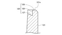
- FIG. 7 is a vertical cross-sectional view schematically showing a swing scroll 12 in the scroll compressor 1 of FIG.
- FIG. 8 is an enlarged cross-sectional view showing a main part of the swing scroll 12 of FIG.
- the fixed side spiral tooth 111 and the swinging side spiral tooth 121 may be described as the spiral teeth 111 and 121 for convenience.
- the compression mechanism unit 10 of the scroll compressor 1 includes a fixed scroll 11 and a swing scroll 12.
- the fixed scroll 11 is fixedly arranged with respect to the frame 6.
- the swing scroll 12 is arranged in the space between the fixed scroll 11 and the frame 6.
- An old dam ring 13 for preventing the swing scroll 12 from rotating is arranged between the swing scroll 12 and the frame 6.
- the old dam ring 13 is arranged on the thrust surface, which is the surface opposite to the upper surface on which the swing side spiral teeth 121 of the swing scroll 12 are formed, and prevents the swing scroll 12 from rotating. That is, the old dam ring 13 has a function of blocking the rotation motion of the swing scroll 12 and enabling the swing motion of the swing scroll 12.
- claw portions are formed so as to project so as to be orthogonal to each other. The claw portion of the old dam ring 13 is fitted into an old dam groove (not shown) formed in the swing scroll 12 and the frame 6, respectively.
- the compression chamber 31 is formed in the space where the spiral teeth 121 mesh with each other.
- the fixed-side spiral tooth 111 is arranged so as to extend downward on the lower surface side of the fixed base plate 110 in the assembled state of the fixed scroll 11. Further, a discharge port 11a for discharging gas as a compressed heating medium is formed through the central portion of the fixed scroll 11. Further, a lead valve 50 is installed at the outlet portion of the discharge port 11a of the fixed scroll 11 so as to cover the outlet portion. The reed valve 50 opens and closes the discharge port 11a to prevent backflow of fluid.
- the valve retainer 51 is a long plate-shaped member thicker than the reed valve 50, and by supporting the reed valve 50 from the back side when the reed valve 50 is opened, the movable range of the reed valve 50 is restricted. , Protect the reed valve 50 from deformation.
- the swing side spiral tooth 121 is arranged so as to extend upward on the upper surface side of the swing base plate 120 in the assembled state of the swing scroll 12.
- the oscillating scroll 12 performs a revolving turning motion, in other words, an oscillating motion with respect to the fixed scroll 11, and the rotation motion is regulated by the old dam ring 13.
- a cylindrical boss portion 122 is formed at the center of the back surface of the swing base plate 120 on the side opposite to the formation surface of the swing side spiral teeth 121.
- a swing bearing 123 is fixed inside the boss portion 122.
- the oscillating bearing 123 is made of a bearing material used for a slide bearing such as a copper-lead alloy, and the bearing material is press-fitted and fixed to the inside of the boss portion 122.
- a slider 4 with a balancer is rotatably arranged inside the swing bearing 123.
- the slider 4 with a balancer has a tubular slider 4a and a first balancer 4b, and these are joined by a technique such as shrink fitting.
- the slider 4a is fitted so as to be relatively movable with respect to the eccentric shaft portion 83 provided at the upper end portion of the spindle 8, and automatically adjusts the swing radius of the swing scroll 12.
- the slider 4a is provided so that the fixed side spiral tooth 111 and the swing side spiral tooth 121 are always in contact with each other when the swing scroll 12 swings.
- the first balancer 4b is located on the side of the slider 4a and is provided to cancel the centrifugal force of the swing scroll 12 and suppress the vibration of the compression element.
- the swing scroll 12 is connected to the eccentric shaft portion 83 of the spindle 8 via the slider 4 with a balancer, and the rotation radius of the spindle 8 is automatically adjusted by the slider 4 with a balancer. It is swung with the movement.
- a tubular bearing operating space 72 is formed between the back surface of the rocking base plate 120 of the rocking scroll 12 and the frame 6.
- the oscillating bearing 123 rotates in the bearing operating space 72 together with the slider 4 with a balancer during the oscillating motion of the oscillating scroll 12.
- a slider having no balancer function may be mounted.
- the centrifugal force applied to the eccentric shaft portion 83 of the spindle 8 increases under high-speed operation conditions. Therefore, it is preferable to use a lightweight material such as an aluminum material as the material of the swing scroll 12 instead of casting. That is, if the swing scroll 12 is light, the weight of the first balancer 4b and, by extension, the slider 4 with a balancer can be reduced, and the cost can be reduced or the size of the scroll compressor 1 can be reduced. Further, by reducing the centrifugal force due to the swing scroll 12 during operation, the load applied to the swing bearing 123 can be reduced and the slidability can be improved.
- the material of the swing scroll 12 is not limited to the aluminum material, and a casting material, a resin material, or the like can also be applied.
- each compression chamber 31 has a crescent-shaped cross section, and the refrigerant taken in from the outer peripheral side is continuously and smoothly compressed toward the center of the spiral to increase the pressure.
- the spiral center side of the fixed side spiral tooth 111 and the swing side spiral tooth 121 is the high pressure side compression chamber 31a, and conversely, the outer peripheral side where the refrigerant is taken in is the low pressure side compression chamber 31b.
- the internal temperature of the compression chamber 31 rises, and the fixed side spiral tooth 111 and the swing side spiral tooth 121 thermally expand, so that the fixed side spiral tooth 111 and the swing side spiral tooth 121 Increases tooth height.
- the tooth height means the height from the tooth bottom 112 located on the fixed base plate 110 side of the fixed-side spiral tooth 111 of the fixed scroll 11, which will be described later, to the tooth tip 111a. ..
- the tooth height is the height from the tooth bottom 124 located on the swing-side plate 120 side of the swing-side spiral tooth 121 of the swing scroll 12, which will be described later, to the tooth tip 121a.
- the fixed side spiral tooth 111 and the swinging side spiral tooth 121 increase due to thermal expansion, as shown in FIGS. 3 and 4, the fixed side spiral tooth 111 and the swinging side spiral tooth 121 A gap is provided between the tooth tips 111a and 121a.
- these tooth tips 111a and 121a and the tooth bottom 124 facing them are used.
- a minute tooth tip gap 33 is formed between and 112.
- the tooth tip gap 33 is provided for the purpose of preventing contact between the tooth tip 111a and the tooth bottom 124 and contact between the tooth tip 121a and the tooth bottom 112 due to thermal expansion.
- the refrigerant leaks from the high-pressure side compression chamber 31a to the low-pressure side compression chamber 31b are radial leakage due to the tooth tip gap 33 (indicated by a solid arrow in FIG. 2) and fixed-side swirl, as shown in FIG.
- a sealing material 3 is provided.
- a molded product of a resin-based material is generally applied, and for example, a PPS (polyphenylene sulfide) -based resin is used.
- the material of the sealing material 3 is not limited to PPS, and is appropriately formed by using one selected from the group containing a polyetheretherketone resin and a polyimide resin according to the intended use. The optimum resin material can be applied.
- the sealing material 3 is a resin molded product, the cross-sectional shape, the total length, and the number of turns can be arbitrarily set, and a material suitable for the compressor application to be mounted can be used.
- the sealing material 3 is arranged and held in the sealing grooves 113 and 125 formed in the tooth tips 111a and 121a of the fixed side spiral tooth 111 and the swinging side spiral tooth 121.
- the seal groove 113 formed at the tooth tip 111a of the fixed side spiral tooth 111 has a bottom surface portion 115 as a bottom portion and a seal material fall prevention portion which is a side wall portion continuous from the bottom surface portion 115. It has a wall 114 and. In this case, the sealing material fall prevention wall 114 is formed only on the outward surface side of the fixed side spiral tooth 111. Further, in the seal groove 113, the side surface portion 116 which is a contact surface with the seal material 3 located on the inner peripheral side of the seal material fall prevention wall 114 continuous from the bottom surface portion 115 is formed perpendicular to the fixed base plate 110. Has been done.
- the seal groove 125 formed at the tooth tip 121a of the swing-side spiral tooth 121 has a bottom surface portion 127 as a bottom portion and a side wall portion continuous from the bottom surface portion 127. It has a sealing material fall prevention wall 126.
- the sealing material fall prevention wall 126 is formed only on the outward surface side of the swing-side spiral tooth 121.
- the side surface portion 128 which is the contact surface with the seal material 3 located on the inner peripheral side of the seal material fall prevention wall 126 continuous from the bottom surface portion 127 is perpendicular to the rocking base plate 120. It is formed.
- the bottom surface 115 of the fixed side spiral tooth 111 has a tooth having a height h1 from the tooth bottom 112 located on the fixed base plate 110 side to the end on the inward surface side of the fixed side spiral tooth 111.
- the height from the bottom 112 to the end of the fixed side spiral tooth 111 on the outward surface side is set higher than h2.
- the bottom surface portion 127 of the swing-side spiral tooth 121 has a height h3 from the tooth bottom 124 located on the swing-side plate 120 side to the end portion of the swing-side spiral tooth 121 on the inward surface side. Is set higher than the height h4 from the tooth bottom 124 to the end of the swing-side spiral tooth 121 on the outward surface side.
- the bottom surface portions 115 and 127 are inclined toward the tooth bottoms 112 and 124 as they proceed from the inward surface side to the outward surface side of the fixed side spiral tooth 111 and the swing side spiral tooth 121.
- the sealing material 3 installed on the tooth tip 111a of the fixed side spiral tooth 111 floats due to the high and low pressure differential pressure between the compression chambers 31 adjacent in the radial direction and the circumferential direction, and as shown in FIG. Is pressed against the sealing material fall prevention wall 114. Further, the sealing material 3 installed on the tooth tip 121a of the swing-side spiral tooth 121 floats due to the high and low pressure differential pressure between the compression chambers 31 adjacent in the radial direction and the circumferential direction, and faces each other as shown in FIG. It is pressed against the tooth bottom 112 and the sealing material fall prevention wall 126. This prevents refrigerant leakage between high and low pressure between the compression chambers 31 adjacent to each other in the radial and circumferential directions as shown in FIG.
- the root portion on the opposite tooth bottom side is used. It was necessary to avoid contact with the tooth tips.
- the root portion is generally connected in a curved shape toward the tooth bottom in order to secure the strength of the spiral tooth. That is, the root portion of the spiral tooth is subjected to so-called R processing.
- R processing the tooth tip is subjected to R processing and chamfering processing with a radius of curvature larger than the radius of curvature of R processing at the root portion of the spiral tooth.
- the sealing material 3 is the tooth bottom 124 and the fixed side spiral tooth 111 of the opposite swing side spiral tooth 121 and the fixed side spiral tooth 111, respectively. It slides in contact with 112. That is, in the case of the first embodiment, the sealing material 3 provided on the tooth tips 111a and 121a is on the tooth bottom 124 and 112 side of the swinging side spiral tooth 121 and the fixed side spiral tooth 111 facing them. It slides along the root. Therefore, it is not necessary to perform R processing and chamfering on the tooth tip with a radius of curvature larger than the radius of curvature of R processing at the root portion of the spiral tooth as in the conventional case. Moreover, as compared with the conventional scroll compressor, it is possible to reduce the leakage of the refrigerant from the high pressure side compression chamber 31a to the low pressure side compression chamber 31b in the compression step.
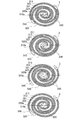
- FIG. 9 is an explanatory diagram showing a state change of the compression chamber 330 in a conventional scroll compressor at 90 ° intervals as a comparative example.
- FIG. 10 is an explanatory diagram showing a state change at 90 ° intervals in the compression chamber 31 of the scroll compressor 1 according to the first embodiment.
- the state of the compression chamber 330 or 31 changing as the spiral tooth 320 or 121 swivels with respect to the spiral tooth 310 or 111 is shown sequentially from the top at 90 ° intervals. There is.
- the sealing grooves 310a and 320a of the spiral teeth 310 and 320 seal the sealing material fall prevention walls 311 and 321 on the outward surface side of the spiral teeth 310 and 320, and also on the inward surface side. It had material fall prevention walls 312 and 322.
- the seal grooves 310a and 320a hold the seal material 3 from both the outward surface side and the inward surface side of the spiral teeth 310 and 320, thereby preventing the seal material 3 from falling during operation.
- the seal grooves 310a and 320a hold the seal material 3 from both the outward surface side and the inward surface side of the spiral teeth 310 and 320, thereby preventing the seal material 3 from falling during operation.
- the seal material fall prevention walls 311, 312 and 321 and 322 are simply made only of the seal material fall prevention walls 311 and 321 on one side on the outward surface side, the seal material fall prevention wall 312 and the seal material fall prevention wall 312 on the inward surface side and Only 322 is removed. Therefore, the contact surface shapes of the sealing material fall prevention walls 311 and 321 that hold the sealing material 3 are only the bottom surface portion (not shown) of the flat sealing groove and the side surface portion (not shown) that follows. Therefore, there is a possibility that the sealing material 3 may fall from the sealing grooves 310a and 320a due to catching with the facing tooth bottom, reversal of the high / low pressure leakage direction in the overcompressed state, or the like. Further, when the sealing material 3 is dropped, there is a concern that the performance may be deteriorated due to damage to the spiral teeth and the discharge port seat surface due to foreign matter biting, and the compressor may be damaged.
- the seal groove 113 of the fixed side spiral tooth 111 of the first embodiment has a tooth having a height h1 from the tooth bottom 112 to the end on the inward surface side of the bottom surface portion 115.
- the height from the bottom 112 to the end of the bottom surface 115 on the outward surface side is set higher than h2.
- the seal groove 125 of the swing-side spiral tooth 121 has a height h3 from the tooth bottom 124 to the end on the inward surface side of the bottom surface portion 127 from the tooth bottom portion 124 to the end portion on the outward surface side of the bottom surface portion 127.
- the height is set higher than h4.
- the seal grooves 113 and 125 of the first embodiment are inclined toward the tooth bottoms 112 and 124 as the bottom surfaces 115 and 127 proceed from the end on the inward surface side to the end on the outward surface side, respectively. ing. Therefore, the bottom surface portions 115 and 127, which are a part of the contact surface shape of the sealing material fall prevention walls 114 and 126 that hold the sealing material 3, are high and low between the end portion on the inward surface side and the end portion on the outward surface side. It has a shape having differences h1-h2 and h3-h4.
- the sealing material fall prevention walls 114 and 126 are provided on only one side of the spiral teeth 111 and 121 on the outward surface side, the sealing material 3 can be dropped due to catching with the opposing tooth bottoms 124 and 112. It can be prevented before it happens. Further, it is possible to prevent the sealing material 3 from falling due to the reversal of the high / low pressure leakage direction in the overcompressed state. Therefore, in the scroll compressor 1 of the first embodiment, the reliability can be improved. Further, by providing the sealing material fall prevention walls 114 and 126 on only one side of the spiral teeth 111 and 121 on the outward surface side, the spiral teeth 111 and each spiral tooth 111 and 121 are compared with the conventional shapes provided on both sides as shown in FIG.
- the tooth thickness which is the thickness of 121, can be reduced by the amount of one side of the sealing material fall prevention wall.
- the scroll compressor 1 of the first embodiment shown in FIG. 10 is compared with a compressor of the same size because the compression chamber 31 can be configured larger and the volume can be expanded as compared with the conventional shape shown in FIG. Therefore, the intake volume can be increased.
- a gap 35 is formed between the bottom surfaces 115 and 127 of the seal grooves 113 and 125 and the seal material 3.
- the dimension d of the gap 35 is a seal from the distance between the lowest portion of one spiral tooth 121 located on the center side of the sealing material fall prevention wall 126 and the other base plate (fixed base plate 110). It is the length obtained by subtracting the longest part of the material 3.
- the height differences h1-h2 and h3-h4 of the bottom surfaces 115 and 127 in the seal grooves 113 and 125 are gaps 35 formed between the bottom portions 115 and 127 and the sealing material 3 at the end portions on the outward surface side. It is desirable that it is larger than the dimension d of.
- the seal groove 113 has a height h1 from the tooth bottom 112 to the end of the bottom surface portion 115 on the inward surface side and an end on the outward surface side of the tooth bottom portion 112 to the bottom surface portion 115. It is desirable that the difference h1-h2 from the height h2 to the portion is set to be larger than the dimension d of the gap 35 between the height h2 and the sealing material 3 at the end portion of the bottom surface portion 115 on the outward surface side.
- the seal groove 125 has a height h3 from the tooth bottom 124 to the end on the inward surface side of the bottom surface portion 127, and an end portion on the outward surface side from the tooth bottom portion 124 to the bottom surface portion 127. It is desirable that the difference h3-h4 from the height h4 up to is set to be larger than the dimension d of the gap 35 between the bottom surface portion 127 and the sealing material 3 at the end portion on the outward surface side.
- the sealing material 3 floats due to the high and low pressure differential pressure between the compression chambers 31, and when the floating amount of the sealing material 3 becomes the above-mentioned height differences h1-h2 and h3-h4 or more of the bottom surfaces 115 and 127, the sealing material 3 There is no element that holds the seal grooves 113 and 125 on the inward surface side. Therefore, the sealing material 3 may fall due to catching with the opposing tooth bottoms 112 and 124 and reversal of the high / low pressure leakage direction in the overcompressed state.
- the dimension d of the gap 35 formed between the bottom surface portions 115 and 127 and the sealing material 3 with the height differences h1-h2 and h3-h4 described above By setting it larger than, it is possible to prevent the sealing material from falling. Since the sealing material 3 expands and contracts thermally, the dimension d of the gap 35 may increase as the temperature decreases. In addition, the dimension d of the gap 35 may increase due to wear. Therefore, it is more desirable that the height differences h1-h2 and h3-h4 are several times as large as the dimension d of the gap 35.
- the sealing material fall prevention wall when the sealing material fall prevention wall is provided on both the outward surface side and the inward surface side of the sealing material, the end portion of the sealing material fall prevention wall, the root portion of the spiral tooth facing the sealing material fall prevention wall, and the root portion of the spiral tooth facing each other. Contact, and spiral damage occurs due to abnormal temperature rise and seizure associated with metal contact. Therefore, when the sealing material fall prevention walls are provided on both sides of the sealing material, the tooth tips are chamfered, and the root portion is R-processed and chamfered. However, there is a concern that a gap is generated in the chamfered portion, which causes the refrigerant to leak in the circumferential direction of the spiral tooth, and deteriorates the performance of the compressor.
- the sealing material 3 is in contact with the opposing root portions.
- leakage loss can be significantly reduced in addition to capacity increase due to volume increase, resulting in a significant performance improvement under low-speed conditions.
- the portion of the sealing material 3 that comes into contact with the root portion of the opposing spiral teeth 111 or 121 may be subjected to R processing or chamfering processing with the same radius of curvature as the root portion.
- FIG. 11 is a schematic cross-sectional view showing the shape of the seal groove 125 formed on the tooth tip 121a located on the center side of the swing-side spiral tooth 121 in the scroll compressor 1 of FIG. Since the seal grooves 113 and 125 on the spiral center side of the spiral teeth 111 and 121 have the same shape, in the following description related to FIG. 11, only the swing side spiral tooth 121 is shown and the fixed side spiral tooth is shown for convenience. The description and illustration of 111 are omitted.
- the seal groove 125 arranged on the spiral center side of the swing-side spiral tooth 121 is located on the inward surface side of the tooth tip 121a. It is also desirable that the sealing material fall prevention wall 129 is formed. That is, in the region where the end portion of the seal material fall prevention wall and the root portion of the spiral tooth facing each other are likely to come into contact with each other, the seal material fall prevention wall 126 is formed only on the outward surface side of the seal groove 125. Then, on the spiral center side where the possibility of such contact is low, the sealing material fall prevention walls 126 and 129 are formed on both the outward surface side and the inward surface side of the seal groove 125.
- the seal material 3 can be reliably held from both the outward surface side and the inward surface side, so that the seal material 3 can be reliably held. It can effectively prevent falling.
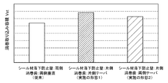
- FIG. 12 is a graph showing a comparison of the spiral intake volumes of the scroll compressor 1 according to the first and second embodiments.
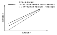
- FIG. 13 is a graph showing the correlation between the rotation speed and the capacity of the scroll compressor 1 according to the first and second embodiments. Note that, for convenience, FIG. 12 shows the spiral intake volume of the scroll compressor 1 according to the second embodiment described later as a comparative example, but detailed description thereof will be omitted here.
- the fixed scroll 11 is inclined so as to taper as the inward surface of the fixed side spiral tooth 111 on the spiral center side advances toward the tooth tip 111a with respect to the fixed base plate 110. That is, the inward surface side of the fixed side spiral tooth 111 is inclined with respect to the tooth bottom 112.
- the swing scroll 12 is inclined so as to taper as the outward surface of the swing side spiral tooth 121 on the refrigerant suction side advances toward the tooth tip with respect to the swing base plate 120. is doing. That is, the swing-side spiral tooth 121 is inclined on the outward surface side with respect to the tooth bottom 124.
- the inclination angles ⁇ of the spiral teeth 111 and 121 are preferably set in the range of 4 ° or less.
- the tooth thickness on the tooth bottom 112 and 124 side of each of the spiral teeth 111 and 121 can be increased, and the strength of each of the spiral teeth 111 and 121 can be improved.
- the outward surface side and the inward surface side, which are opposite sides of the inclined inward surface side and the outward surface side of the spiral teeth 111 and 121, are formed perpendicular to the tooth bottoms 112 and 124.
- the tooth thickness on the root 112 and 124 sides of the conventionally vertical spiral teeth 111 and 121 increases. Will be done.
- the inclination angle ⁇ is 4 ° or less, the amount of increase in the tooth thickness is small, and the contribution of the volume reduction to the increase in the intake volume due to the one-sided sealing material fall prevention walls 114 and 126 is small.
- the increase in tooth thickness applied to the actual configuration of the compression chamber 31 by overlapping with the opposing spiral teeth 121 and 111 is only one side of the increased tooth thickness on the tooth bottom 112 and 124 sides.
- the sealing material fall prevention walls 114 and 126 unilateral and making the spiral teeth 111 and 121 tapered on one side, the spiral pitch becomes large even if the involute range and the base circle constituting the spiral are the same. Therefore, as shown in the first and second embodiments of FIG. 12, the intake volume of the compression chamber 31 can be expanded. Moreover, there is no need to improve other parts or add components, and it is possible to increase the intake volume with the same involute. Therefore, as shown in the first and second embodiments of FIG. 13, the maximum capacity of the scroll compressor 1 alone can be improved without increasing the manufacturing cost.
- the pressure difference between the adjacent compression chambers 31 becomes large. Due to this pressure difference, if the stress generated at the root of each of the spiral teeth 111 and 121 exceeds the proof stress of the material or is repeatedly applied, the spiral teeth 111 and 121 may be damaged and the scroll compressor 1 may stop. There is. As described above, in the conventional spiral tooth having the sealing material fall prevention wall on only one side, the spiral tooth is simply thinned by making the sealing material fall prevention wall on one side, so that the refrigerant can be taken in. While the volume has been increased, the spiral strength is reduced. Therefore, the reliability of the compressor is lowered.
- the scroll compressor 1 of the first embodiment by forming one side of each of the spiral teeth 111 and 121 into a tapered shape, it is possible to improve the strength at the root of each of the spiral teeth 111 and 121. It is said.
- the height difference is provided by providing an inclination on the outward surface side of the swing-side spiral tooth 121 whose material rigidity is lowered as the material of the swing scroll 12 is reduced in weight. The stress generated at the root of the swing-side spiral tooth 121 due to the pressure can be reduced more efficiently.
- the gas-state refrigerant sucked into the shell 2 from the suction pipe 101 is compressed formed between the spiral teeth 111 and 121 of the fixed scroll 11 and the swing scroll 12. It is taken into the chamber 31 and compressed toward the center. Then, the compressed refrigerant is discharged by opening the reed valve 50 from the discharge port 11a of the fixed scroll 11, and is discharged from the discharge pipe 102 to the outside of the scroll compressor 1, that is, to the refrigerant circuit.
- the imbalance caused by the movement of the swing scroll 12 and the old dam ring 13 is balanced and stabilized by the first balancer 4b attached to the spindle 8 and the second balancer 8a attached to the rotor 21 side. .. Further, the refrigerating machine oil 9a stored in the oil sump portion 9 at the lower part of the shell 2 passes through the oil supply passage 82 provided in the main shaft 8 to each sliding portion such as the main bearing 15, the auxiliary bearing 16 and the thrust surface. Be supplied.
- the sealing material fall prevention walls 114 and 126 are placed on the outward surface side of the sealing grooves 113 and 125 of the fixed side spiral teeth 111 and the swinging side spiral teeth 121. I tried to install it only. At this time, the height h1 of the seal groove 113 from the tooth bottom 112 to the end on the inward surface side of the bottom surface 115 is higher than the height h2 from the tooth bottom 112 to the end on the outward surface side of the bottom surface 115. It is set high.
- the seal groove 125 of the swing-side spiral tooth 121 has a height h3 from the tooth bottom 124 to the end on the inward surface side of the bottom surface portion 127 from the tooth bottom portion 124 to the end portion on the outward surface side of the bottom surface portion 127.
- the height is set higher than h4. That is, the seal grooves 113 and 125 are inclined toward the tooth bottoms 112 and 124 as the bottom surfaces 115 and 127 on which the seal material 3 is arranged proceed from the end on the inward surface side to the end on the outward surface side, respectively. Therefore, the high pressure side is set to be higher than the low pressure side.
- the thickness of the spiral teeth 111 and 121 is increased by providing the sealing material fall prevention walls 114 and 126 only on the outward surface side of the sealing grooves 113 and 125. It can be thinned, the swirl uptake volume can be increased, and the upper limit of the compressor capacity can be increased. Further, by raising the high pressure side of the bottom surfaces 115 and 127 on which the sealing material 3 is arranged, it is possible to prevent the sealing material 3 from falling during operation. Thus, according to the scroll compressor 1 of the first embodiment, it is possible to improve the performance while ensuring the reliability.
- the scroll compressor 1 of the first embodiment by providing the spiral teeth 111 and 121 with an inclination angle ⁇ , it is possible to counter the stress applied to the roots of the spiral teeth 111 and 121. , The strength of the spiral teeth 111 and 121 can be improved.
- FIG. 14 is a schematic cross-sectional view showing the shape of the seal groove 125 at the tooth tip 121a of the swing-side spiral tooth 121 of the scroll compressor 1 according to the modified example of the first embodiment.
- the shapes of the seal grooves 113 and 125 in the fixed side spiral tooth 111 and the swing side spiral tooth 121 are substantially the same, for convenience, only the swing side spiral tooth 121 is used as a modification.
- the fixed side spiral tooth 111 is similarly configured.
- the seal groove 113 is in contact with the seal material 3 located on the inner peripheral side of the seal material fall prevention wall 114 continuous from the bottom surface portion 115.
- the seal groove 125 has a side surface portion 128 which is a contact surface with the seal material 3 located on the inner peripheral side of the seal material fall prevention wall 126 which is continuous from the bottom surface portion 127.
- the rocking base plate 120 is formed perpendicular to the rocking base plate 120 has been described.
- these side surface portions 116 and 128 are not limited to being formed perpendicular to the fixed base plate 110 and the swing base plate 120.
- the seal groove 125 at the tooth tip 121a of the spiral tooth 121 is a seal material located on the inner peripheral side of the seal material fall prevention wall 126.
- the side surface portion 128, which is the contact surface with 3 may be perpendicular to the bottom surface portion 127. That is, in this case, the side surface portion 128 is not perpendicular to the rocking base plate 120 but is inclined. In this way, the side surface portion 128, which is a part of the contact surface shape of the sealing material fall prevention wall 126 that holds the sealing material 3, is inclined with respect to the rocking base plate 120, so that the side surface portion 128 becomes the rocking base.
- the holding force of the sealing material 3 can be improved as compared with the case where the sealing material 3 is perpendicular to the plate 120. Therefore, the ability to prevent the sealing material 3 from falling off during operation can be significantly improved.
- FIG. 15 is a vertical cross-sectional view schematically showing a fixed scroll 11 of the scroll compressor 1 according to the second embodiment.
- FIG. 16 is a vertical cross-sectional view schematically showing a swing scroll 12 of the scroll compressor 1 according to the second embodiment. It should be noted that FIGS. 15 and 16 are shown by assigning the same reference numerals to the portions corresponding to those of FIGS. 5 and 7, respectively, and a detailed description of the same components as those of the first embodiment described below will be described below. Is omitted.
- the fixed scroll 11 has not only the inward surface on the spiral center side of the fixed side spiral tooth 111 but also the outward surface on the back side thereof with respect to the fixed base plate 110.
- the fixed side spiral tooth 111 has an inward surface side and an outward surface side inclined with respect to the tooth bottom 112, respectively.
- the swing scroll 12 not only the outward surface of the swing side spiral tooth 121 on the refrigerant suction side but also the inward surface on the back side thereof has teeth with respect to the swing base plate 120. It slopes to taper as it progresses. That is, the swing-side spiral tooth 121 is inclined on the outward surface side and the inward surface side with respect to the tooth bottom 124.
- the inclination angles ⁇ of the spiral teeth 111 and 121 are preferably set in the range of 4 ° or less.
- the tooth thickness on the roots 112 and 124 sides of the spiral teeth 111 and 121 can be further increased, and the strength of the spiral teeth 111 and 121 can be further improved.
- the inclination angles ⁇ on the inward surface side and the outward surface side of the spiral teeth 111 and 121 are the same, but the magnitude relationship between them can be set arbitrarily.
- FIG. 17 is a schematic cross-sectional view showing the shape of the seal groove 125 at the tooth tip 121a of the swing-side spiral tooth 121 of the scroll compressor 1 according to the third embodiment. It should be noted that FIG. 17 is shown by adding the same reference numerals to the portions corresponding to those in FIG. 8 described above, and detailed description of the same components as those in the first embodiment described above will be omitted below. Further, although only the swing-side spiral tooth 121 will be illustrated and described here, the fixed-side spiral tooth 111 may have the same configuration as that of FIG.
- the sealing material 3 is arranged on the tooth tip 121a of the swing-side spiral tooth 121 over the entire area of the tooth tip 121a so as to cover the entire tooth tip 121a.
- the sealing material fall prevention walls 311, 312, 321 and 322 are present on both the inward and outward surfaces of the spiral teeth 310 and 320, so that the ends of the tooth tips are made of metal. (See FIG. 9). Therefore, the tooth tip and the tooth bottom are subjected to arbitrary R processing and chamfering processing, respectively, for the purpose of preventing metal contact with the tooth bottoms of the opposing spiral teeth 320 and 310.
- the minute circumferential gap 34 (see FIG. 4) generated when the R processing and the chamfering processing overlap each other becomes a circumferential leakage path in the spiral teeth 310 and 320, which causes a decrease in compressor performance.
- the sealing material 3 is arranged so as to exist over the entire area of the tooth tip 121a.
- the sealing material 3 is arranged so as to exist over the entire area of the tooth tip 121a, and the end located at the tip of the swing-side spiral tooth 121.
- the portion is not a metal but a resin of the sealing material 3. Therefore, the operation can be performed in a state of being in contact with the root portion of the opposing fixed side spiral teeth 111 (see FIG. 4), and the loss due to the circumferential leakage can be reduced.
- FIG. 18 is a refrigerant circuit diagram showing an example of the refrigeration cycle device according to the fourth embodiment.
- the refrigeration cycle device 200 functions as an air conditioner that performs cooling or heating operation to harmonize the air in the room by transferring heat between the outside air and the air in the room via a refrigerant, for example.
- the refrigeration cycle device 200 includes a scroll compressor 1, a condenser 201, an expansion valve 202 as a depressurizing device, and an evaporator 203. Further, the refrigeration cycle device 200 includes an injection circuit 204 that branches from between the condenser 201 and the expansion valve 202 and is connected to the scroll compressor 1. The injection circuit 204 is provided with a flow rate adjusting valve 205.
- the scroll compressor 1 of the above-described first to third embodiments can be applied to the scroll compressor 1.
- the gas refrigerant discharged from the scroll compressor 1 flows into the condenser 201, exchanges heat with the air passing through the condenser 201, and flows out as a high-pressure liquid refrigerant. ..
- the high-pressure liquid refrigerant flowing out of the condenser 201 is depressurized by the expansion valve 202 to become a low-pressure gas-liquid two-phase refrigerant, and flows into the evaporator 203.
- the low-pressure gas-liquid two-phase refrigerant flowing into the evaporator 203 exchanges heat with the air passing through the evaporator 203 to become a low-pressure gas refrigerant, which is again sucked into the scroll compressor 1.
- the injection refrigerant which is a part of the refrigerant discharged from the scroll compressor 1 and passed through the condenser 201, flows into the injection circuit 204, flows into the injection pipe 103 of the scroll compressor 1 through the flow rate adjusting valve 205. ..
- the liquid or gas-liquid two-phase injection refrigerant that has flowed into the injection pipe 103 is injected into the spiral-side suction space 73 or the compression chamber 31.
- the refrigeration cycle device 200 configured in this way can synergize with the increase in the spiral intake volume and further improve the compression function force.
- the refrigerating cycle device 200 equipped with the scroll compressor 1 can be applied to a refrigerator, a freezer, a vending machine, an air conditioner, a refrigerating device, a water heater, or the like.
- 1 scroll compressor 2 shell, 2a upper shell, 2b lower shell, 2c body shell, 3 sealant, 4 slider with balancer, 4a slider, 4b first balancer, 6 frame, 6a shaft hole, 7 subframe, 8 spindle , 8a 2nd balancer, 9 oil reservoir, 9a refrigerating machine oil, 10 compression mechanism, 11 fixed scroll, 11a discharge port, 12 swing scroll, 12b swing side spiral tooth, 13 old dam ring, 14 sleeve, 15 main bearing , 16 auxiliary bearing, 20 motor, 21 rotor, 22 stator, 31 compression chamber, 31a high pressure side compression chamber, 31b low pressure side compression chamber, 33 tooth tip gap, 34 circumferential gap, 35 gap, 40 injection mechanism, 50 lead valve , 51 valve retainer, 70 suction space, 71 discharge space, 72 bearing operating space, 73 swirl side suction space, 81 oil pump, 82 refueling passage, 83 eccentric shaft part, 84 main shaft part, 85 sub-shaft part, 101 suction pipe, 102 discharge pipe, 103 injection
Abstract
According to the invention, a fixed scroll and an orbiting scroll each have a seal groove for retaining a seal material at the addendums of a fixed-side scroll tooth and an orbiting-side scroll tooth, the seal groove having a seal material dropping prevention wall as a side surface part, and a bottom surface part. The seal material dropping prevention walls are each formed on outward facing surface sides of the fixed-side scroll tooth and the orbiting-side scroll tooth. The bottom surface parts are set so that the height, from tooth bottoms positioned on a fixed base plate side and an orbiting base plate side to end parts on the inward facing surface sides of the fixed-side scroll tooth and the orbiting-side scroll tooth of the bottom surface parts, is greater than the height from the tooth bottom to the end sections on the outward facing surface sides of the fixed-side scroll tooth and the orbiting-side scroll tooth of the bottom surface parts. As a result, the tooth thickness of the scroll teeth is made thinner whereby the scroll intake volume can be increased and the upper limit of the capacity of the compressor can be increased, and the high pressure side is increased at the bottom surface part where the seal material is disposed whereby dropping of the seal material during operation can be prevented ahead of time. Accordingly, while ensuring reliability, it is possible to improve performance.
Description
本開示は、スクロール圧縮機およびそれを備えた冷凍サイクル装置に関する。
The present disclosure relates to a scroll compressor and a refrigeration cycle device equipped with the scroll compressor.
スクロール圧縮機は、固定台板上に突出して形成されたインボリュート形状の渦巻歯を有する固定スクロールと、揺動台板上に突出して形成されたインボリュート形状の渦巻歯を有する揺動スクロールと、を互いの渦巻歯が噛み合うように備えている。このとき、固定スクロールおよび揺動スクロールは、互いの渦巻歯の位相が相対的に180°ずれた状態で、互いの渦巻側面が接触している。そして、固定スクロールに対して揺動スクロールを公転運動させ、これら固定スクロールと揺動スクロールとにより構成される複数の圧縮室を外方側から内方側に向かって次第に減少させることで、圧縮機内部の冷媒ガスを圧縮する。これにより、スクロール圧縮機は、圧縮室内部の圧縮した冷媒ガスを、中心部の吐出口から吐出させる。
The scroll compressor includes a fixed scroll having an involute-shaped spiral tooth formed so as to project on a fixed base plate and a swing scroll having an involute-shaped spiral tooth formed so as to project on a rocking base plate. It is prepared so that the spiral teeth of each other mesh with each other. At this time, in the fixed scroll and the swing scroll, the spiral side surfaces of the fixed scroll and the swing scroll are in contact with each other in a state where the phases of the spiral teeth are relatively shifted by 180 °. Then, the oscillating scroll is revolved with respect to the fixed scroll, and the plurality of compression chambers composed of the fixed scroll and the oscillating scroll are gradually reduced from the outer side to the inner side, thereby causing the compressor. Compress the internal refrigerant gas. As a result, the scroll compressor discharges the compressed refrigerant gas in the compression chamber from the discharge port in the central portion.
このようなスクロール圧縮機では、圧縮した冷媒ガスが隣接する圧縮室へ漏れるのを抑制する目的で、固定スクロールおよび揺動スクロールが、互いの渦巻歯の歯先を相手側の台板に密接させた状態で噛み合わされる。そのため、固定スクロールおよび揺動スクロールの渦巻歯は、圧縮過程において圧縮された冷媒ガスによる荷重を受けることにより、それぞれの台板である固定台板側および揺動台板側に位置する根元部に応力が発生する。そこで、このようなスクロール圧縮機では、渦巻中心における根元部の角隅と、これに対向する相手側の渦巻歯の歯先とに、それぞれ湾曲形状を形成する加工、所謂、Rをつける加工が施されていた。
In such a scroll compressor, the fixed scroll and the swing scroll bring the tips of the spiral teeth into close contact with the mating plate in order to prevent the compressed refrigerant gas from leaking to the adjacent compression chamber. It is meshed in the state of being Therefore, the spiral teeth of the fixed scroll and the swing scroll are subjected to the load of the refrigerant gas compressed in the compression process, so that they are located at the roots located on the fixed base plate side and the swing base plate side, which are the respective base plates. Stress is generated. Therefore, in such a scroll compressor, a process of forming a curved shape at the corner of the root portion at the center of the spiral and the tip of the spiral tooth on the opposite side of the root portion, that is, a process of adding a so-called R, is performed. It was given.
ここで、空気調和装置、冷凍機、および、給湯機等に搭載されるスクロール圧縮機には、シェル外被に触れる空間が圧縮工程後の高圧冷媒で満たされる高圧シェルと、圧縮工程前の低圧冷媒で満たされる低圧シェルと、の2つのタイプがある。従来、低圧シェルを有するスクロール圧縮機の渦巻歯の歯先には、圧縮室間の漏れを防止するためシール材を設ける必要がある。そのため、このようなスクロール圧縮機では、稼動時にシール材が渦巻歯の歯先から滑落するのを防止するべく、シール材の両側にシール材落下防止壁を設けていた。ところが、この場合、シール材保持のためにシール材落下防止壁の厚みを確保しなければならず、シール材落下防止壁を設けることが渦巻歯の厚さの薄肉化における制限となっていた。
Here, in the scroll compressor mounted on the air conditioner, the refrigerator, the water heater, etc., a high-pressure shell in which the space in contact with the shell jacket is filled with the high-pressure refrigerant after the compression process and a low-pressure before the compression process There are two types: low pressure shells filled with refrigerant. Conventionally, it is necessary to provide a sealing material at the tooth tips of the spiral teeth of a scroll compressor having a low-pressure shell in order to prevent leakage between compression chambers. Therefore, in such a scroll compressor, in order to prevent the sealing material from slipping off from the tip of the spiral tooth during operation, the sealing material fall prevention walls are provided on both sides of the sealing material. However, in this case, it is necessary to secure the thickness of the sealing material fall prevention wall in order to hold the sealing material, and providing the sealing material fall prevention wall is a limitation in thinning the thickness of the spiral teeth.
そこで、渦巻歯の歯厚の薄肉化を行うため、シール材落下防止壁をシール材の片側のみに形成するものが提案されている(例えば、特許文献1参照)。特許文献1のスクロール圧縮機では、シール材落下防止壁をシール材の片側にのみ設けることで、渦巻歯の歯厚を薄肉化して圧縮室を大きく構成し、同一サイズの圧縮機と比較して取り込み容積の大容量化を図っていた。
Therefore, in order to reduce the thickness of the spiral teeth, it has been proposed to form a sealing material fall prevention wall on only one side of the sealing material (see, for example, Patent Document 1). In the scroll compressor of Patent Document 1, by providing the sealing material fall prevention wall only on one side of the sealing material, the tooth thickness of the spiral teeth is thinned to form a large compression chamber, and the compression chamber is made larger than that of a compressor of the same size. The intake volume was increased.
ところが、特許文献1に記載の圧縮機では、シール材落下防止壁をシール材の片側のみで構成したため、相対する歯底面との引っ掛かり、または、過圧縮状態における高低圧漏れ方向の逆転により、シール材が溝から落下する可能性があった。このように、特許文献1に記載の圧縮機では、信頼性の面で懸念する課題があった。
However, in the compressor described in Patent Document 1, since the sealing material fall prevention wall is composed of only one side of the sealing material, the seal is sealed due to catching with the opposing tooth bottom surface or reversal of the high / low pressure leakage direction in the overcompressed state. The material could fall out of the groove. As described above, the compressor described in Patent Document 1 has a problem of concern in terms of reliability.
本開示は、上述した課題を解決するためのものであり、信頼性を確保しつつ、性能の向上を図ることが可能なスクロール圧縮機およびそれを備えた冷凍サイクル装置を提供することを目的とするものである。
The present disclosure is to solve the above-mentioned problems, and an object of the present invention is to provide a scroll compressor capable of improving performance while ensuring reliability, and a refrigeration cycle device equipped with the scroll compressor. To do.
本開示に係るスクロール圧縮機は、固定台板上に突出して形成されたインボリュート形状の固定側渦巻歯と、前記固定側渦巻歯の歯先に設けられたシール材と、を有する固定スクロールと、揺動台板上に突出して形成されたインボリュート形状の揺動側渦巻歯と、前記揺動側渦巻歯の歯先に設けられたシール材と、を有する揺動スクロールと、を備え、前記固定スクロールと前記揺動スクロールとが、互いの前記固定側渦巻歯と前記揺動側渦巻歯とを噛み合うように組み合わされ、前記固定スクロールと前記揺動スクロールとの間に冷媒を圧縮する圧縮室が形成されたスクロール圧縮機であって、前記固定スクロールおよび前記揺動スクロールは、それぞれ前記固定側渦巻歯および前記揺動側渦巻歯の歯先に、前記シール材を保持するためのシール溝が形成され、前記シール溝は、底部となる底面部と、前記底面部から連続して側壁部となるシール材落下防止壁と、を有し、前記シール材落下防止壁は、前記固定側渦巻歯および前記揺動側渦巻歯における外向面側に形成されており、前記固定側渦巻歯における前記底面部は、前記固定台板側に位置する歯底から前記固定側渦巻歯における内向面側の端部までの高さが、前記歯底から前記固定側渦巻歯における外向面側の端部までの高さよりも高く設定されており、前記揺動側渦巻歯における前記底面部は、前記揺動台板側に位置する歯底から前記揺動側渦巻歯における内向面側の端部までの高さが、前記歯底から前記揺動側渦巻歯における外向面側の端部までの高さよりも高く設定されているものである。
The scroll compressor according to the present disclosure includes a fixed scroll having an involut-shaped fixed-side spiral tooth formed so as to project on a fixed base plate and a sealing material provided at the tip of the fixed-side spiral tooth. A swing scroll having an involut-shaped swing side spiral tooth formed so as to project on a swing base plate and a sealing material provided at the tip of the swing side spiral tooth is provided, and the fixing thereof is provided. The scroll and the swinging scroll are combined so as to mesh with each other of the fixed side spiral tooth and the swinging side spiral tooth, and a compression chamber for compressing the refrigerant is provided between the fixed scroll and the swinging scroll. In the formed scroll compressor, in the fixed scroll and the swinging scroll, a sealing groove for holding the sealing material is formed at the tooth tips of the fixed side spiral tooth and the swinging side spiral tooth, respectively. The seal groove has a bottom surface portion which is a bottom portion and a sealing material fall prevention wall which is a side wall portion continuous from the bottom surface portion, and the sealing material fall prevention wall includes the fixed side spiral teeth and the sealing material fall prevention wall. It is formed on the outward surface side of the swinging side spiral tooth, and the bottom surface portion of the fixed side spiral tooth is an end portion on the inward surface side of the fixed side spiral tooth from the tooth bottom located on the fixed base plate side. The height up to is set higher than the height from the tooth bottom to the end on the outward surface side of the fixed side spiral tooth, and the bottom surface portion of the swing side spiral tooth is the rocking base plate. The height from the tooth bottom located on the side to the end on the inward surface side of the swing-side spiral tooth is set higher than the height from the tooth bottom to the end on the outward surface side of the swing-side spiral tooth. It is what has been done.
また、本開示に係る冷凍サイクル装置は、少なくとも圧縮機、凝縮器、膨張弁および蒸発器を有する冷媒回路を備え、前記圧縮機として上記のスクロール圧縮機を用いたものである。
Further, the refrigeration cycle apparatus according to the present disclosure includes a refrigerant circuit having at least a compressor, a condenser, an expansion valve and an evaporator, and uses the scroll compressor as the compressor.
本開示によれば、シール材落下防止壁を固定側渦巻歯および揺動側渦巻歯のシール溝における外向面側のみに設けることにより、渦巻歯の歯厚を薄肉化させることで、渦巻取り込み容積を拡大し、圧縮機の能力の上限を拡大できる。また、底面部は、固定台板および揺動台板側に位置する歯底から底面部の固定側渦巻歯および揺動側渦巻歯における内向面側の端部までの高さが、歯底から底面部の固定側渦巻歯および揺動側渦巻歯における外向面側の端部までの高さよりも高く設定されている。すなわち、シール材を配置する底面部において高圧側を高くすることにより、運転中のシール材落下を未然に防止できる。かくして、本開示に係るスクロール圧縮機およびそれを備えた冷凍サイクル装置によれば、信頼性を確保しつつ、性能の向上を図ることができる。
According to the present disclosure, by providing the sealing material fall prevention wall only on the outward surface side of the sealing groove of the fixed side spiral tooth and the swinging side spiral tooth, the tooth thickness of the spiral tooth is thinned, so that the spiral intake volume is reduced. Can be expanded to increase the upper limit of the compressor capacity. In addition, the height of the bottom surface from the tooth bottom located on the fixed base plate and the swing base plate side to the end on the inward surface side of the fixed side spiral tooth and the swing side spiral tooth on the bottom surface is from the tooth bottom. It is set higher than the height to the end on the outward surface side of the fixed side spiral tooth and the swing side spiral tooth on the bottom surface. That is, by raising the high pressure side of the bottom surface on which the sealing material is arranged, it is possible to prevent the sealing material from falling during operation. Thus, according to the scroll compressor according to the present disclosure and the refrigeration cycle apparatus provided with the scroll compressor, it is possible to improve the performance while ensuring the reliability.
以下、本開示に係るスクロール圧縮機および冷凍サイクル装置の実施の形態について、添付の図面を参照しながら説明する。なお、明細書全文および図面に示す構成要素の形態は、あくまで例示であってこれらの記載に限定されるものではない。すなわち、本開示は、請求の範囲および明細書全体から読み取ることのできる要旨または思想に反しない範囲で適宜変更可能である。また、そのような変更を伴うスクロール圧縮機および冷凍サイクル装置も本開示の技術思想に含まれる。さらに、各図において、同一の符号を付したものは、各図において、同一の符号を付したものは、同一のまたはこれに相当するものであり、これは明細書の全文において共通している。
Hereinafter, embodiments of the scroll compressor and refrigeration cycle apparatus according to the present disclosure will be described with reference to the attached drawings. The forms of the components shown in the full text of the specification and the drawings are merely examples and are not limited to these descriptions. That is, the present disclosure can be appropriately modified to the extent that it does not contradict the gist or idea that can be read from the scope of claims and the entire specification. Scroll compressors and refrigeration cycle devices with such changes are also included in the technical concepts of the present disclosure. Further, those having the same reference numerals in each figure, those having the same reference numerals in each figure are the same or equivalent, and this is common in the entire text of the specification. ..
実施の形態1.
<スクロール圧縮機1の構成>
図1~図3を参照しながら、実施の形態1に係るスクロール圧縮機1について説明する。図1は、実施の形態1に係るスクロール圧縮機1の縦断面を概略的に示す説明図である。図2は、図1のスクロール圧縮機1における圧縮室31の横断面を概略的に示す説明図である。図3は、図1のスクロール圧縮機1における圧縮室31の一部を拡大して概略的に示す縦断面図である。Embodiment 1.
<Structure ofscroll compressor 1>
Thescroll compressor 1 according to the first embodiment will be described with reference to FIGS. 1 to 3. FIG. 1 is an explanatory view schematically showing a vertical cross section of the scroll compressor 1 according to the first embodiment. FIG. 2 is an explanatory view schematically showing a cross section of the compression chamber 31 in the scroll compressor 1 of FIG. FIG. 3 is an enlarged vertical cross-sectional view of a part of the compression chamber 31 in the scroll compressor 1 of FIG.
<スクロール圧縮機1の構成>
図1~図3を参照しながら、実施の形態1に係るスクロール圧縮機1について説明する。図1は、実施の形態1に係るスクロール圧縮機1の縦断面を概略的に示す説明図である。図2は、図1のスクロール圧縮機1における圧縮室31の横断面を概略的に示す説明図である。図3は、図1のスクロール圧縮機1における圧縮室31の一部を拡大して概略的に示す縦断面図である。
<Structure of
The
図1に示すように、スクロール圧縮機1は、密閉容器であるシェル2の内部に、圧縮機構部10と、当該圧縮機構部10を駆動する電動機構としてのモータ20と、を備えている。本実施の形態1の場合、スクロール圧縮機1は、シェル2内が圧縮機構部10で圧縮される前の冷媒で満たされる、いわゆる低圧シェル型の圧縮機である。スクロール圧縮機1で圧縮される冷媒には、例えば二酸化炭素が用いられる。なお、冷媒は二酸化炭素に限定するものはなく、他の冷媒を広く適用できる。
As shown in FIG. 1, the scroll compressor 1 includes a compression mechanism unit 10 and a motor 20 as an electric mechanism for driving the compression mechanism unit 10 inside a shell 2 which is a closed container. In the case of the first embodiment, the scroll compressor 1 is a so-called low-pressure shell type compressor in which the inside of the shell 2 is filled with the refrigerant before being compressed by the compression mechanism unit 10. For example, carbon dioxide is used as the refrigerant compressed by the scroll compressor 1. The refrigerant is not limited to carbon dioxide, and other refrigerants can be widely applied.
シェル2は、アッパーシェル2aと、ロアーシェル2bと、胴部シェル2cとを有してスクロール圧縮機1の外殻を構成し、下部に油溜り部9を有する。シェル2は、有底円筒状であり、ドーム状のアッパーシェル2aによって胴部シェル2cの上部が塞がれ、ロアーシェル2bによって胴部シェル2cの下部が塞がれている。
The shell 2 has an upper shell 2a, a lower shell 2b, and a body shell 2c to form an outer shell of the scroll compressor 1, and has an oil sump portion 9 at the lower part. The shell 2 has a bottomed cylindrical shape, and the upper part of the body shell 2c is closed by the dome-shaped upper shell 2a, and the lower part of the body shell 2c is closed by the lower shell 2b.
圧縮機構部10は、固定スクロール11と揺動スクロール12とを有して構成されている。図1に示すように、固定スクロール11は、固定台板110と、この固定台板110上に設けられたインボリュート形状の固定側渦巻歯111と、を備えている。揺動スクロール12は、揺動台板120と、この揺動台板120上に設けられたインボリュート形状の揺動側渦巻歯121と、を備えている。また、図2および図3に示すように、これら固定側渦巻歯111および揺動側渦巻歯121の歯先111aおよび121aには、後述するシール材3が配置されている。そして、圧縮機構部10は、固定スクロール11の固定側渦巻歯111と、揺動スクロール12の揺動側渦巻歯121と、を主軸8の回転中心に対して逆位相で噛み合わせた対称渦巻形状の状態でシェル2内に配置されている。
The compression mechanism unit 10 includes a fixed scroll 11 and a swing scroll 12. As shown in FIG. 1, the fixed scroll 11 includes a fixed base plate 110 and an involute-shaped fixed side spiral tooth 111 provided on the fixed base plate 110. The oscillating scroll 12 includes a oscillating base plate 120 and an involute-shaped oscillating side spiral tooth 121 provided on the oscillating base plate 120. Further, as shown in FIGS. 2 and 3, the sealing material 3 described later is arranged on the tooth tips 111a and 121a of the fixed side spiral tooth 111 and the swinging side spiral tooth 121. Then, the compression mechanism unit 10 has a symmetrical spiral shape in which the fixed-side spiral teeth 111 of the fixed scroll 11 and the swing-side spiral teeth 121 of the swing scroll 12 are meshed with each other in opposite phases with respect to the rotation center of the spindle 8. It is arranged in the shell 2 in the state of.
圧縮機構部10は、フレーム6によって支持されている。フレーム6は、焼嵌めまたは溶接等によってシェル2の内周面に固着されている。フレーム6は、シェル2内において圧縮機構部10とモータ20との間に配置されている。フレーム6の中央部には軸孔6aが形成されており、この軸孔6aに主軸8が通されている。シェル2内において、モータ20の下方には、サブフレーム7が設けられている。サブフレーム7は、焼嵌めまたは溶接等によってシェル2の内周面に固着されている。
The compression mechanism unit 10 is supported by the frame 6. The frame 6 is fixed to the inner peripheral surface of the shell 2 by shrink fitting, welding, or the like. The frame 6 is arranged between the compression mechanism unit 10 and the motor 20 in the shell 2. A shaft hole 6a is formed in the central portion of the frame 6, and the main shaft 8 is passed through the shaft hole 6a. In the shell 2, a subframe 7 is provided below the motor 20. The subframe 7 is fixed to the inner peripheral surface of the shell 2 by shrink fitting, welding, or the like.
モータ20は、回転子としてのロータ21と固定子としてのステータ22とを有して構成されており、シェル2の内部にて、フレーム6とサブフレーム7との間に設置され、主軸8を介して圧縮機構部10を駆動する。ロータ21は、ステータ22の内周側に設けられ、主軸8に取り付けられる。ステータ22は、外部から電力を得るために、フレーム6とステータ22との間に存在する不図示のガラス端子に不図示のリード線で接続されている。そして、ステータ22は、外部から供給された電力によってロータ21を回転させる。ロータ21は、自転することにより、主軸8を回転させる。
The motor 20 includes a rotor 21 as a rotor and a stator 22 as a stator, and is installed inside the shell 2 between the frame 6 and the subframe 7 to provide a spindle 8. The compression mechanism unit 10 is driven via the system. The rotor 21 is provided on the inner peripheral side of the stator 22, and is attached to the spindle 8. The stator 22 is connected to a glass terminal (not shown) existing between the frame 6 and the stator 22 by a lead wire (not shown) in order to obtain electric power from the outside. Then, the stator 22 rotates the rotor 21 by the electric power supplied from the outside. The rotor 21 rotates on its axis to rotate the spindle 8.
主軸8は、モータ20のロータ21が焼嵌めなどの手法によって固定され、ロータ21の回転に伴って回転することで、圧縮機構部10を駆動させる。また、スクロール圧縮機1の下部に位置する油溜り部9には冷凍機油9aが貯油されている。主軸8の下端部には給油機構としてのオイルポンプ81が固着されている。オイルポンプ81は、例えばトロコイドポンプなどの容積型ポンプである。オイルポンプ81は、主軸8の回転に従い、油溜り部9に溜められている冷凍機油9aを、主軸8の内部に形成された給油通路82を通して汲み上げる。汲み上げられた冷凍機油9aは、揺動軸受123の潤滑および圧縮室31の隙間のシールを目的として、揺動軸受123および圧縮室31に供給される。
The main shaft 8 is fixed by a method such as shrink fitting of the rotor 21 of the motor 20, and rotates with the rotation of the rotor 21 to drive the compression mechanism portion 10. Further, the refrigerating machine oil 9a is stored in the oil sump portion 9 located at the lower part of the scroll compressor 1. An oil pump 81 as a refueling mechanism is fixed to the lower end of the main shaft 8. The oil pump 81 is a positive displacement pump such as a trochoidal pump. The oil pump 81 pumps the refrigerating machine oil 9a stored in the oil reservoir 9 through the oil supply passage 82 formed inside the spindle 8 according to the rotation of the spindle 8. The pumped refrigerating machine oil 9a is supplied to the oscillating bearing 123 and the compression chamber 31 for the purpose of lubricating the oscillating bearing 123 and sealing the gap of the compression chamber 31.
主軸8において、偏心軸部83よりも下方には、主軸部84が設けられている。偏心軸部83は、主軸部84に対して偏心した位置に配置されている。主軸部84は、スリーブ14を介して主軸受15に嵌入しており、冷凍機油9aによる油膜を介して主軸受15に対し摺動する。主軸受15は、銅鉛合金などの滑り軸受に使用される軸受材料を圧入するなどしてフレーム6に固定されている。
In the spindle 8, a spindle 84 is provided below the eccentric shaft 83. The eccentric shaft portion 83 is arranged at a position eccentric with respect to the spindle portion 84. The spindle portion 84 is fitted into the main bearing 15 via the sleeve 14, and slides with respect to the main bearing 15 via an oil film made of refrigerating machine oil 9a. The main bearing 15 is fixed to the frame 6 by press-fitting a bearing material used for a slide bearing such as a copper-lead alloy.
スリーブ14は、フレーム6と主軸受15との間に設けられる筒状の部材である。スリーブ14は、フレーム6と主軸8との傾斜を吸収する。
The sleeve 14 is a tubular member provided between the frame 6 and the main bearing 15. The sleeve 14 absorbs the inclination of the frame 6 and the spindle 8.
スライダ4aは、主軸8の上部の外周面に取り付けられる筒状の部材である。スライダ4aは、揺動スクロール12の下部の内側面に位置する。すなわち、揺動スクロール12は、スライダ4aを介して主軸8に取り付けられる。これにより、主軸8の回転に伴って揺動スクロール12が回転する。なお、揺動スクロール12とスライダ4aとの間には、揺動軸受123が設けられる。
The slider 4a is a tubular member attached to the outer peripheral surface of the upper part of the spindle 8. The slider 4a is located on the inner surface of the lower part of the swing scroll 12. That is, the swing scroll 12 is attached to the spindle 8 via the slider 4a. As a result, the swing scroll 12 rotates as the spindle 8 rotates. A swing bearing 123 is provided between the swing scroll 12 and the slider 4a.
第一バランサ4bは、主軸8に取り付けられる。第一バランサ4bは、フレーム6とロータ21との間に位置する。第一バランサ4bは、揺動スクロール12およびスライダ4aによって生じるアンバランスを相殺する。
The first balancer 4b is attached to the spindle 8. The first balancer 4b is located between the frame 6 and the rotor 21. The first balancer 4b offsets the imbalance caused by the swing scroll 12 and the slider 4a.
第二バランサ8aは、主軸8に取り付けられる。第二バランサ8aは、ロータ21とサブフレーム7との間に位置し、ロータ21の下面に取り付けられる。第二バランサ8aは、揺動スクロール12およびスライダ4aによって生じるアンバランスを相殺する。
The second balancer 8a is attached to the spindle 8. The second balancer 8a is located between the rotor 21 and the subframe 7, and is attached to the lower surface of the rotor 21. The second balancer 8a offsets the imbalance caused by the swing scroll 12 and the slider 4a.
サブフレーム7は、シェル2の内部におけるモータ20の下方に設けられ、副軸受16を介して主軸8を回転自在に支持する。サブフレーム7の中央部は、玉軸受からなる副軸受16を備え、モータ20の下方で主軸8を半径方向に軸支する。なお、副軸受16は、玉軸受以外の別の軸受構成としてもよい。主軸8においてモータ20よりも下方の副軸部85は、副軸受16と嵌め合わされ、冷凍機油9aによる油膜を介して副軸受16に対し摺動する。主軸部84および副軸部85の軸心は、主軸8の軸心と一致している。
The subframe 7 is provided below the motor 20 inside the shell 2 and rotatably supports the spindle 8 via the auxiliary bearing 16. The central portion of the subframe 7 includes an auxiliary bearing 16 made of ball bearings, and supports the main shaft 8 in the radial direction below the motor 20. The auxiliary bearing 16 may have a bearing configuration other than the ball bearing. The sub-shaft portion 85 of the main shaft 8 below the motor 20 is fitted with the sub-bearing 16 and slides with respect to the sub-bearing 16 via an oil film of refrigerating machine oil 9a. The axial centers of the main shaft portion 84 and the sub-shaft portion 85 coincide with the axial centers of the main shaft 8.
シェル2には、冷媒を吸入するための吸入管101と、冷媒を吐出するための吐出管102と、が設けられている。吸入管101は、シェル2の側壁部に設けられる。吸入管101は、ガス状態の冷媒をシェル2の内部に吸入する管である。シェル2内において、フレーム6よりも下方には、吸入管101から流入した吸入冷媒で満たされる低圧の吸入空間70が形成されている。
The shell 2 is provided with a suction pipe 101 for sucking the refrigerant and a discharge pipe 102 for discharging the refrigerant. The suction pipe 101 is provided on the side wall portion of the shell 2. The suction pipe 101 is a pipe that sucks the gaseous refrigerant into the shell 2. In the shell 2, a low-pressure suction space 70 filled with the suction refrigerant flowing in from the suction pipe 101 is formed below the frame 6.
吐出管102は、シェル2の上部に設けられる。吐出管102は、圧縮された冷媒をシェル2の外部に吐出する管である。また、シェル2内において、圧縮機構部10の固定スクロール11における固定台板110より上方に位置する吐出管102側には、圧縮機構部10から吐出された吐出冷媒で満たされる高圧の吐出空間71が形成されている。シェル2の上方には、外部から導入される冷媒を、後述する揺動側渦巻歯12bの外周側に位置する冷媒の吸入空間73、または、後述する圧縮室31内に噴射するインジェクション機構40のインジェクション管103が接続されていることが好ましい。
The discharge pipe 102 is provided on the upper part of the shell 2. The discharge pipe 102 is a pipe that discharges the compressed refrigerant to the outside of the shell 2. Further, in the shell 2, the discharge pipe 102 located above the fixed base plate 110 in the fixed scroll 11 of the compression mechanism unit 10 is filled with a high-pressure discharge space 71 filled with the discharge refrigerant discharged from the compression mechanism unit 10. Is formed. Above the shell 2, an injection mechanism 40 that injects a refrigerant introduced from the outside into a refrigerant suction space 73 located on the outer peripheral side of the swing-side spiral tooth 12b, which will be described later, or into a compression chamber 31, which will be described later. It is preferable that the injection tube 103 is connected.
<圧縮機構部10>
次に、前述した図1~図3に加え、図4~図8を用いて、本実施の形態1に係るスクロール圧縮機1の圧縮機構部10について説明する。図4は、図3の圧縮室31における要部Aを示す拡大断面図である。図5は、図1のスクロール圧縮機1における固定スクロール11を概略的に示す縦断面図である。図6は、図5の固定スクロール11の要部Bを示す拡大断面図である。図7は、図1のスクロール圧縮機1における揺動スクロール12を概略的に示す縦断面図である。図8は、図7の揺動スクロール12の要部を示す拡大断面図である。なお、以下の説明では、固定側渦巻歯111および揺動側渦巻歯121を便宜上、各渦巻歯111および121として説明する場合がある。 <Compression mechanism 10>
Next, in addition to FIGS. 1 to 3 described above, thecompression mechanism portion 10 of the scroll compressor 1 according to the first embodiment will be described with reference to FIGS. 4 to 8. FIG. 4 is an enlarged cross-sectional view showing a main part A in the compression chamber 31 of FIG. FIG. 5 is a vertical cross-sectional view schematically showing a fixed scroll 11 in the scroll compressor 1 of FIG. FIG. 6 is an enlarged cross-sectional view showing a main part B of the fixed scroll 11 of FIG. FIG. 7 is a vertical cross-sectional view schematically showing a swing scroll 12 in the scroll compressor 1 of FIG. FIG. 8 is an enlarged cross-sectional view showing a main part of the swing scroll 12 of FIG. In the following description, the fixed side spiral tooth 111 and the swinging side spiral tooth 121 may be described as the spiral teeth 111 and 121 for convenience.
次に、前述した図1~図3に加え、図4~図8を用いて、本実施の形態1に係るスクロール圧縮機1の圧縮機構部10について説明する。図4は、図3の圧縮室31における要部Aを示す拡大断面図である。図5は、図1のスクロール圧縮機1における固定スクロール11を概略的に示す縦断面図である。図6は、図5の固定スクロール11の要部Bを示す拡大断面図である。図7は、図1のスクロール圧縮機1における揺動スクロール12を概略的に示す縦断面図である。図8は、図7の揺動スクロール12の要部を示す拡大断面図である。なお、以下の説明では、固定側渦巻歯111および揺動側渦巻歯121を便宜上、各渦巻歯111および121として説明する場合がある。 <
Next, in addition to FIGS. 1 to 3 described above, the
図1に示すように、スクロール圧縮機1の圧縮機構部10は、固定スクロール11と揺動スクロール12とを有して構成されている。固定スクロール11は、フレーム6に対して固定配置されている。揺動スクロール12は、固定スクロール11とフレーム6との間の空間に配置されている。揺動スクロール12とフレーム6との間には、揺動スクロール12の自転を防止するためのオルダムリング13が配置されている。
As shown in FIG. 1, the compression mechanism unit 10 of the scroll compressor 1 includes a fixed scroll 11 and a swing scroll 12. The fixed scroll 11 is fixedly arranged with respect to the frame 6. The swing scroll 12 is arranged in the space between the fixed scroll 11 and the frame 6. An old dam ring 13 for preventing the swing scroll 12 from rotating is arranged between the swing scroll 12 and the frame 6.
オルダムリング13は、揺動スクロール12の揺動側渦巻歯121の形成される上面とは反対側の面であるスラスト面に配置され、揺動スクロール12の自転運動を阻止する。すなわち、オルダムリング13は、揺動スクロール12の自転運動を阻止すると共に、揺動スクロール12の揺動運動を可能とする機能を果たす。オルダムリング13の上下面には、それぞれ互いに直交するように突設された不図示の爪部が形成される。オルダムリング13の爪部は、揺動スクロール12およびフレーム6に形成される不図示のオルダム溝にそれぞれ嵌入される。
The old dam ring 13 is arranged on the thrust surface, which is the surface opposite to the upper surface on which the swing side spiral teeth 121 of the swing scroll 12 are formed, and prevents the swing scroll 12 from rotating. That is, the old dam ring 13 has a function of blocking the rotation motion of the swing scroll 12 and enabling the swing motion of the swing scroll 12. On the upper and lower surfaces of the old dam ring 13, claw portions (not shown) are formed so as to project so as to be orthogonal to each other. The claw portion of the old dam ring 13 is fitted into an old dam groove (not shown) formed in the swing scroll 12 and the frame 6, respectively.
そして、固定スクロール11と揺動スクロール12とが、固定側渦巻歯111と揺動側渦巻歯121とを互いに噛み合うように対向させて設置されることで、これら固定側渦巻歯111と揺動側渦巻歯121とが噛み合った空間に圧縮室31が形成される。揺動スクロール12が主軸8によって揺動運動されると、圧縮室31にてガス状態の冷媒が圧縮される。なお、圧縮室31の詳細については後述する。
Then, the fixed scroll 11 and the swing scroll 12 are installed so that the fixed side spiral tooth 111 and the swing side spiral tooth 121 are opposed to each other so as to mesh with each other, so that the fixed side spiral tooth 111 and the swing side are installed. The compression chamber 31 is formed in the space where the spiral teeth 121 mesh with each other. When the oscillating scroll 12 is oscillated by the spindle 8, the gas-state refrigerant is compressed in the compression chamber 31. The details of the compression chamber 31 will be described later.
具体的に、図1に示すように、固定側渦巻歯111は、固定スクロール11の組付状態において、固定台板110の下面側に下方に延びて配置される。また、固定スクロール11の中央部には、圧縮された加熱媒体としてのガスを吐出する吐出口11aが貫通して形成されている。さらに、固定スクロール11の吐出口11aの出口部には、当該出口部を覆うようにリード弁50が設置される。リード弁50は、吐出口11aを開閉し、流体の逆流を防止するものである。弁押え51は、リード弁50よりも厚みのある長板状の部材であり、リード弁50の開弁時にリード弁50を背面側から支持することで、リード弁50の可動範囲を規制しつつ、リード弁50が変形しないように保護する。
Specifically, as shown in FIG. 1, the fixed-side spiral tooth 111 is arranged so as to extend downward on the lower surface side of the fixed base plate 110 in the assembled state of the fixed scroll 11. Further, a discharge port 11a for discharging gas as a compressed heating medium is formed through the central portion of the fixed scroll 11. Further, a lead valve 50 is installed at the outlet portion of the discharge port 11a of the fixed scroll 11 so as to cover the outlet portion. The reed valve 50 opens and closes the discharge port 11a to prevent backflow of fluid. The valve retainer 51 is a long plate-shaped member thicker than the reed valve 50, and by supporting the reed valve 50 from the back side when the reed valve 50 is opened, the movable range of the reed valve 50 is restricted. , Protect the reed valve 50 from deformation.
また、揺動側渦巻歯121は、揺動スクロール12の組付状態において、揺動台板120の上面側に上方に延びて配置される。揺動スクロール12は、固定スクロール11に対して公転旋回運動、換言すれば揺動運動を行い、オルダムリング13によって自転運動が規制される。
Further, the swing side spiral tooth 121 is arranged so as to extend upward on the upper surface side of the swing base plate 120 in the assembled state of the swing scroll 12. The oscillating scroll 12 performs a revolving turning motion, in other words, an oscillating motion with respect to the fixed scroll 11, and the rotation motion is regulated by the old dam ring 13.
揺動スクロール12の揺動台板120において、揺動側渦巻歯121の形成面とは反対側の背面の中心部には、円筒状のボス部122が形成されている。ボス部122の内側には揺動軸受123が固定されている。揺動軸受123は、銅鉛合金などの滑り軸受に使用される軸受材料で構成され、軸受材料がボス部122の内側に圧入されて固定されている。
In the swing base plate 120 of the swing scroll 12, a cylindrical boss portion 122 is formed at the center of the back surface of the swing base plate 120 on the side opposite to the formation surface of the swing side spiral teeth 121. A swing bearing 123 is fixed inside the boss portion 122. The oscillating bearing 123 is made of a bearing material used for a slide bearing such as a copper-lead alloy, and the bearing material is press-fitted and fixed to the inside of the boss portion 122.
そして、揺動軸受123の内側にはバランサ付スライダ4が回転自在に配置されている。バランサ付スライダ4は、筒状のスライダ4aと、第一バランサ4bと、を有して構成され、これらは焼嵌めなどの手法を用いて接合されている。スライダ4aは、主軸8の上端部に設けられた後述の偏心軸部83に対して相対移動可能に嵌め合わされ、揺動スクロール12の揺動半径を自動的に調整する。スライダ4aは、揺動スクロール12の揺動時に常に固定側渦巻歯111と揺動側渦巻歯121とが互いに接した状態となるように設けられている。第一バランサ4bは、スライダ4aの側方に位置し、揺動スクロール12の遠心力を打ち消して圧縮要素の振動を抑えるために設けられている。
Then, a slider 4 with a balancer is rotatably arranged inside the swing bearing 123. The slider 4 with a balancer has a tubular slider 4a and a first balancer 4b, and these are joined by a technique such as shrink fitting. The slider 4a is fitted so as to be relatively movable with respect to the eccentric shaft portion 83 provided at the upper end portion of the spindle 8, and automatically adjusts the swing radius of the swing scroll 12. The slider 4a is provided so that the fixed side spiral tooth 111 and the swing side spiral tooth 121 are always in contact with each other when the swing scroll 12 swings. The first balancer 4b is located on the side of the slider 4a and is provided to cancel the centrifugal force of the swing scroll 12 and suppress the vibration of the compression element.
このように、揺動スクロール12は、主軸8の偏心軸部83にバランサ付スライダ4を介して連結されており、バランサ付スライダ4によって揺動半径が自動的に調整されつつ、主軸8の回転に伴って揺動運動される。揺動スクロール12の揺動台板120における背面とフレーム6との間には、筒状の軸受動作空間72が形成されている。揺動軸受123は、揺動スクロール12の揺動運動中、バランサ付スライダ4と共に軸受動作空間72内を回転するようになっている。なお、バランサ付スライダ4に替えて、バランサ機能を有さないスライダが搭載されていてもよい。
In this way, the swing scroll 12 is connected to the eccentric shaft portion 83 of the spindle 8 via the slider 4 with a balancer, and the rotation radius of the spindle 8 is automatically adjusted by the slider 4 with a balancer. It is swung with the movement. A tubular bearing operating space 72 is formed between the back surface of the rocking base plate 120 of the rocking scroll 12 and the frame 6. The oscillating bearing 123 rotates in the bearing operating space 72 together with the slider 4 with a balancer during the oscillating motion of the oscillating scroll 12. In addition, instead of the slider 4 with a balancer, a slider having no balancer function may be mounted.
揺動スクロール12は、主軸8の回転数に応じて公転運動されるため、高速運転条件下において主軸8の偏心軸部83に加わる遠心力が増加する。このため、揺動スクロール12の素材には鋳物ではなく、アルミニウム材などの軽量素材を用いることが好ましい。つまり、揺動スクロール12が軽ければ第一バランサ4b、ひいてはバランサ付スライダ4を軽量化でき、コスト削減またはスクロール圧縮機1のサイズダウンを図ることができる。また、運転時の揺動スクロール12による遠心力を小さくすることで、揺動軸受123にかかる荷重を低減でき、摺動性を向上できる、といった多くのメリットを有する。なお、揺動スクロール12の素材はアルミニウム材に限定されるものではなく、鋳物系素材、または、樹脂系素材等も適用できる。
Since the swing scroll 12 revolves according to the rotation speed of the spindle 8, the centrifugal force applied to the eccentric shaft portion 83 of the spindle 8 increases under high-speed operation conditions. Therefore, it is preferable to use a lightweight material such as an aluminum material as the material of the swing scroll 12 instead of casting. That is, if the swing scroll 12 is light, the weight of the first balancer 4b and, by extension, the slider 4 with a balancer can be reduced, and the cost can be reduced or the size of the scroll compressor 1 can be reduced. Further, by reducing the centrifugal force due to the swing scroll 12 during operation, the load applied to the swing bearing 123 can be reduced and the slidability can be improved. The material of the swing scroll 12 is not limited to the aluminum material, and a casting material, a resin material, or the like can also be applied.
また、図1および図2に示すように、固定側渦巻歯111と揺動側渦巻歯121との間には、主軸8の回転に伴い、半径方向外周側から内側の渦巻中心側へ向かうにしたがって、容積が縮小される複数の圧縮室31が形成される。各圧縮室31は、それぞれ横断面が三日月形状をなし、外周側から取り込まれた冷媒が、渦巻中心に向かって連続的かつ滑らかに圧縮されることにより昇圧し、渦巻体中心に近づくほど高温となる。
Further, as shown in FIGS. 1 and 2, between the fixed side spiral tooth 111 and the swinging side spiral tooth 121, as the spindle 8 rotates, the direction from the outer peripheral side in the radial direction toward the inner spiral center side. Therefore, a plurality of compression chambers 31 whose volume is reduced are formed. Each compression chamber 31 has a crescent-shaped cross section, and the refrigerant taken in from the outer peripheral side is continuously and smoothly compressed toward the center of the spiral to increase the pressure. Become.
すなわち、これら複数の圧縮室31は、固定側渦巻歯111および揺動側渦巻歯121の渦巻中心側が高圧側圧縮室31aとなり、反対に冷媒が取り込まれる外周側が低圧側圧縮室31bとなる。このような圧縮工程に伴い圧縮室31の内部温度は上昇し、固定側渦巻歯111と揺動側渦巻歯121とが熱膨張することで、これら固定側渦巻歯111および揺動側渦巻歯121の歯高が増加する。
That is, in these plurality of compression chambers 31, the spiral center side of the fixed side spiral tooth 111 and the swing side spiral tooth 121 is the high pressure side compression chamber 31a, and conversely, the outer peripheral side where the refrigerant is taken in is the low pressure side compression chamber 31b. With such a compression step, the internal temperature of the compression chamber 31 rises, and the fixed side spiral tooth 111 and the swing side spiral tooth 121 thermally expand, so that the fixed side spiral tooth 111 and the swing side spiral tooth 121 Increases tooth height.
ここで、歯高とは、固定側渦巻歯111の場合、後述する固定スクロール11の固定側渦巻歯111における固定台板110側に位置する歯底112から歯先111aまでの高さを意味する。また、揺動側渦巻歯121の場合、歯高とは、後述する揺動スクロール12の揺動側渦巻歯121における揺動台板120側に位置する歯底124から歯先121aまでの高さを意味する。
Here, in the case of the fixed-side spiral tooth 111, the tooth height means the height from the tooth bottom 112 located on the fixed base plate 110 side of the fixed-side spiral tooth 111 of the fixed scroll 11, which will be described later, to the tooth tip 111a. .. Further, in the case of the swing-side spiral tooth 121, the tooth height is the height from the tooth bottom 124 located on the swing-side plate 120 side of the swing-side spiral tooth 121 of the swing scroll 12, which will be described later, to the tooth tip 121a. Means.
前述のように、固定側渦巻歯111および揺動側渦巻歯121の歯高が熱膨張により増加するため、図3および図4に示すように、固定側渦巻歯111および揺動側渦巻歯121の歯先111aおよび121aには隙間が設けられている。具体的に、固定スクロール11と揺動スクロール12とが、固定側渦巻歯111と揺動側渦巻歯121とを噛み合わせた際、これらの歯先111aおよび121aと、それらに対向する歯底124および112との間には、微小な歯先隙間33が形成されるようになっている。
As described above, since the tooth heights of the fixed side spiral tooth 111 and the swinging side spiral tooth 121 increase due to thermal expansion, as shown in FIGS. 3 and 4, the fixed side spiral tooth 111 and the swinging side spiral tooth 121 A gap is provided between the tooth tips 111a and 121a. Specifically, when the fixed scroll 11 and the swing scroll 12 mesh the fixed side spiral tooth 111 and the swing side spiral tooth 121, these tooth tips 111a and 121a and the tooth bottom 124 facing them are used. A minute tooth tip gap 33 is formed between and 112.
この歯先隙間33は、熱膨張により、歯先111aと歯底124との接触、および、歯先121aと歯底112との接触を、それぞれ未然に防ぐことを目的として設けられる。この場合、高圧側圧縮室31aから低圧側圧縮室31bへの冷媒漏れは、図2に示すように、歯先隙間33による径方向漏れ(図2中、実線矢印で示す)と、固定側渦巻歯111と揺動側渦巻歯121との側面同士が接した際に発生する微小な周方向隙間34による周方向漏れ(図2中、破線矢印で示す)と、がある。
The tooth tip gap 33 is provided for the purpose of preventing contact between the tooth tip 111a and the tooth bottom 124 and contact between the tooth tip 121a and the tooth bottom 112 due to thermal expansion. In this case, the refrigerant leaks from the high-pressure side compression chamber 31a to the low-pressure side compression chamber 31b are radial leakage due to the tooth tip gap 33 (indicated by a solid arrow in FIG. 2) and fixed-side swirl, as shown in FIG. There is a circumferential leakage (indicated by a broken arrow in FIG. 2) due to a minute circumferential gap 34 that occurs when the side surfaces of the tooth 111 and the swinging side spiral tooth 121 come into contact with each other.
そこで、本実施の形態1の圧縮機構部10では、図2~図4に示すように、固定側渦巻歯111および揺動側渦巻歯121の歯先111aおよび121aに、渦巻形状に沿って連続するシール材3が設けられている。シール材3は、一般に樹脂系素材の成型品が適用されることが多く、例えばPPS(ポリフェニレンサルファイド)系樹脂が用いられる。なお、シール材3の材質は、PPSに限定されるものではなく、使用する用途に応じて適宜、ポリエーテルエーテルケトン系樹脂およびポリイミド系樹脂を含む群から選択された一種を用いて形成される最適な樹脂材を適用可能となっている。また、シール材3は、樹脂成型品のため、断面形状、全長および巻き数を任意に設定できるものであり、搭載される圧縮機用途に適したものを使用できる。シール材3は、固定側渦巻歯111および揺動側渦巻歯121の歯先111aおよび121aに形成されたシール溝113および125に配置され保持される。
Therefore, in the compression mechanism portion 10 of the first embodiment, as shown in FIGS. 2 to 4, the teeth tips 111a and 121a of the fixed side spiral tooth 111 and the swing side spiral tooth 121 are continuous along the spiral shape. A sealing material 3 is provided. As the sealing material 3, a molded product of a resin-based material is generally applied, and for example, a PPS (polyphenylene sulfide) -based resin is used. The material of the sealing material 3 is not limited to PPS, and is appropriately formed by using one selected from the group containing a polyetheretherketone resin and a polyimide resin according to the intended use. The optimum resin material can be applied. Further, since the sealing material 3 is a resin molded product, the cross-sectional shape, the total length, and the number of turns can be arbitrarily set, and a material suitable for the compressor application to be mounted can be used. The sealing material 3 is arranged and held in the sealing grooves 113 and 125 formed in the tooth tips 111a and 121a of the fixed side spiral tooth 111 and the swinging side spiral tooth 121.
ここで、固定側渦巻歯111および揺動側渦巻歯121の歯先111aおよび121aに形成されたシール溝113および125について、図4~図8を用いて説明する。
Here, the seal grooves 113 and 125 formed in the tooth tips 111a and 121a of the fixed side spiral tooth 111 and the swing side spiral tooth 121 will be described with reference to FIGS. 4 to 8.
図4~図6に示すように、固定側渦巻歯111の歯先111aに形成されたシール溝113は、底部となる底面部115と、底面部115から連続した側壁部となるシール材落下防止壁114と、を有している。この場合、シール材落下防止壁114は、固定側渦巻歯111における外向面側のみに形成されている。また、シール溝113は、底面部115から連続したシール材落下防止壁114の内周側に位置するシール材3との接面である側面部116が、固定台板110に対して垂直に形成されている。
As shown in FIGS. 4 to 6, the seal groove 113 formed at the tooth tip 111a of the fixed side spiral tooth 111 has a bottom surface portion 115 as a bottom portion and a seal material fall prevention portion which is a side wall portion continuous from the bottom surface portion 115. It has a wall 114 and. In this case, the sealing material fall prevention wall 114 is formed only on the outward surface side of the fixed side spiral tooth 111. Further, in the seal groove 113, the side surface portion 116 which is a contact surface with the seal material 3 located on the inner peripheral side of the seal material fall prevention wall 114 continuous from the bottom surface portion 115 is formed perpendicular to the fixed base plate 110. Has been done.
図4、図7および図8に示すように、揺動側渦巻歯121の歯先121aに形成されたシール溝125は、底部となる底面部127と、底面部127から連続して側壁部となるシール材落下防止壁126と、を有している。この場合、シール材落下防止壁126は、揺動側渦巻歯121における外向面側のみに形成されている。また、シール溝125は、底面部127から連続したシール材落下防止壁126の内周側に位置するシール材3との接面である側面部128が、揺動台板120に対して垂直に形成されている。
As shown in FIGS. 4, 7 and 8, the seal groove 125 formed at the tooth tip 121a of the swing-side spiral tooth 121 has a bottom surface portion 127 as a bottom portion and a side wall portion continuous from the bottom surface portion 127. It has a sealing material fall prevention wall 126. In this case, the sealing material fall prevention wall 126 is formed only on the outward surface side of the swing-side spiral tooth 121. Further, in the seal groove 125, the side surface portion 128 which is the contact surface with the seal material 3 located on the inner peripheral side of the seal material fall prevention wall 126 continuous from the bottom surface portion 127 is perpendicular to the rocking base plate 120. It is formed.
固定側渦巻歯111における底面部115は、図4に示すように、固定台板110側に位置する歯底112から固定側渦巻歯111における内向面側の端部までの高さh1が、歯底112から固定側渦巻歯111における外向面側の端部までの高さh2よりも高く設定されている。
As shown in FIG. 4, the bottom surface 115 of the fixed side spiral tooth 111 has a tooth having a height h1 from the tooth bottom 112 located on the fixed base plate 110 side to the end on the inward surface side of the fixed side spiral tooth 111. The height from the bottom 112 to the end of the fixed side spiral tooth 111 on the outward surface side is set higher than h2.
揺動側渦巻歯121における底面部127は、図4に示すように、揺動台板120側に位置する歯底124から揺動側渦巻歯121における内向面側の端部までの高さh3が、歯底124から揺動側渦巻歯121における外向面側の端部までの高さh4よりも高く設定されている。
As shown in FIG. 4, the bottom surface portion 127 of the swing-side spiral tooth 121 has a height h3 from the tooth bottom 124 located on the swing-side plate 120 side to the end portion of the swing-side spiral tooth 121 on the inward surface side. Is set higher than the height h4 from the tooth bottom 124 to the end of the swing-side spiral tooth 121 on the outward surface side.
換言すれば、底面部115および127は、固定側渦巻歯111および揺動側渦巻歯121における内向面側から外向面側に進むにつれ、歯底112および124に向かって傾斜している。
In other words, the bottom surface portions 115 and 127 are inclined toward the tooth bottoms 112 and 124 as they proceed from the inward surface side to the outward surface side of the fixed side spiral tooth 111 and the swing side spiral tooth 121.
固定側渦巻歯111の歯先111aに設置されたシール材3は、径方向および周方向に隣接する圧縮室31間の高低圧差圧により浮上し、図4に示すように、相対する歯底124と、シール材落下防止壁114と、に押し付けられる。また、揺動側渦巻歯121の歯先121aに設置されたシール材3は、径方向および周方向に隣接する圧縮室31間の高低圧差圧により浮上し、図4に示すように、相対する歯底112と、シール材落下防止壁126と、に押し付けられる。これにより、図2に示すような径方向および周方向に隣接する圧縮室31間における高低圧間の冷媒漏れを防ぐ。
The sealing material 3 installed on the tooth tip 111a of the fixed side spiral tooth 111 floats due to the high and low pressure differential pressure between the compression chambers 31 adjacent in the radial direction and the circumferential direction, and as shown in FIG. Is pressed against the sealing material fall prevention wall 114. Further, the sealing material 3 installed on the tooth tip 121a of the swing-side spiral tooth 121 floats due to the high and low pressure differential pressure between the compression chambers 31 adjacent in the radial direction and the circumferential direction, and faces each other as shown in FIG. It is pressed against the tooth bottom 112 and the sealing material fall prevention wall 126. This prevents refrigerant leakage between high and low pressure between the compression chambers 31 adjacent to each other in the radial and circumferential directions as shown in FIG.
ここで、図示省略するが、歯先において、シール溝が外向面側と内向面側との両サイドにシール材落下防止壁を有する従来形状の渦巻歯では、相対する歯底側の根元部と歯先との接触を避ける必要があった。根元部は、渦巻歯の強度確保のため、歯底に向かって湾曲した形状で接続されていることが一般的である。つまり、渦巻歯の根元部には、いわゆるR加工が施されている。このため、従来では、渦巻歯の根元部におけるR加工の曲率半径より大きい曲率半径で歯先にR加工および面取り加工を施していた。
Although not shown here, in the case of a conventional spiral tooth having a seal groove having a seal material fall prevention wall on both the outward surface side and the inward surface side at the tooth tip, the root portion on the opposite tooth bottom side is used. It was necessary to avoid contact with the tooth tips. The root portion is generally connected in a curved shape toward the tooth bottom in order to secure the strength of the spiral tooth. That is, the root portion of the spiral tooth is subjected to so-called R processing. For this reason, conventionally, the tooth tip is subjected to R processing and chamfering processing with a radius of curvature larger than the radius of curvature of R processing at the root portion of the spiral tooth.
これに対し、本実施の形態1の固定側渦巻歯111および揺動側渦巻歯121であればシール材3が、それぞれ相対する揺動側渦巻歯121および固定側渦巻歯111の歯底124および112と接した状態で摺動する。すわなち、本実施の形態1の場合、歯先111aおよび121aに設けられたシール材3が、それらに対向する揺動側渦巻歯121および固定側渦巻歯111の歯底124および112側の根元部に沿った状態で摺動する。このため、従来のような、渦巻歯の根元部におけるR加工の曲率半径より大きい曲率半径で歯先にR加工および面取り加工を施す必要はない。その上、従来のスクロール圧縮機と比較し、圧縮工程において高圧側圧縮室31aから低圧側圧縮室31bへの冷媒漏れを低減させることが可能となっている。
On the other hand, in the case of the fixed side spiral tooth 111 and the swing side spiral tooth 121 of the first embodiment, the sealing material 3 is the tooth bottom 124 and the fixed side spiral tooth 111 of the opposite swing side spiral tooth 121 and the fixed side spiral tooth 111, respectively. It slides in contact with 112. That is, in the case of the first embodiment, the sealing material 3 provided on the tooth tips 111a and 121a is on the tooth bottom 124 and 112 side of the swinging side spiral tooth 121 and the fixed side spiral tooth 111 facing them. It slides along the root. Therefore, it is not necessary to perform R processing and chamfering on the tooth tip with a radius of curvature larger than the radius of curvature of R processing at the root portion of the spiral tooth as in the conventional case. Moreover, as compared with the conventional scroll compressor, it is possible to reduce the leakage of the refrigerant from the high pressure side compression chamber 31a to the low pressure side compression chamber 31b in the compression step.
図9は、従来のスクロール圧縮機における圧縮室330の90°毎の状態変化を比較例として示す説明図である。図10は、実施の形態1に係るスクロール圧縮機1の圧縮室31における90°毎の状態変化を示す説明図である。なお、図9および図10では、渦巻歯320または121が渦巻歯310または111に対して旋回することにより、圧縮室330または31が状態変化する様子を、それぞれ上から順次90°毎に示している。
FIG. 9 is an explanatory diagram showing a state change of the compression chamber 330 in a conventional scroll compressor at 90 ° intervals as a comparative example. FIG. 10 is an explanatory diagram showing a state change at 90 ° intervals in the compression chamber 31 of the scroll compressor 1 according to the first embodiment. In addition, in FIGS. 9 and 10, the state of the compression chamber 330 or 31 changing as the spiral tooth 320 or 121 swivels with respect to the spiral tooth 310 or 111 is shown sequentially from the top at 90 ° intervals. There is.
図9に示すように、従来、各渦巻歯310および320のシール溝310aおよび320aは、各渦巻歯310および320の外向面側にシール材落下防止壁311および321を、同じく内向面側にシール材落下防止壁312および322を、有していた。これにより、シール溝310aおよび320aは、各渦巻歯310および320の外向面側と内向面側との両側からシール材3を保持することで、運転中にシール材3が落下するのを防止していた。ここで、従来のシール材落下防止壁311、312および321、322を単純に外向面側の片側のシール材落下防止壁311および321のみとした場合、内向面側のシール材落下防止壁312および322を取り除いただけとなる。したがって、シール材3を保持するシール材落下防止壁311および321の接面形状が、平坦なシール溝の底面部(不図示)と、それに続く側面部(不図示)のみとなる。よって、相対する歯底との引っ掛かり、または、過圧縮状態における高低圧漏れ方向の逆転等により、シール材3がシール溝310aおよび320aから落下する可能性がある。また、シール材3が落下した場合、異物噛み込みによる渦巻歯および吐出ポート座面の損傷による性能低下、並びに、圧縮機破損等が懸念される。
As shown in FIG. 9, conventionally, the sealing grooves 310a and 320a of the spiral teeth 310 and 320 seal the sealing material fall prevention walls 311 and 321 on the outward surface side of the spiral teeth 310 and 320, and also on the inward surface side. It had material fall prevention walls 312 and 322. As a result, the seal grooves 310a and 320a hold the seal material 3 from both the outward surface side and the inward surface side of the spiral teeth 310 and 320, thereby preventing the seal material 3 from falling during operation. Was there. Here, when the conventional seal material fall prevention walls 311, 312 and 321 and 322 are simply made only of the seal material fall prevention walls 311 and 321 on one side on the outward surface side, the seal material fall prevention wall 312 and the seal material fall prevention wall 312 on the inward surface side and Only 322 is removed. Therefore, the contact surface shapes of the sealing material fall prevention walls 311 and 321 that hold the sealing material 3 are only the bottom surface portion (not shown) of the flat sealing groove and the side surface portion (not shown) that follows. Therefore, there is a possibility that the sealing material 3 may fall from the sealing grooves 310a and 320a due to catching with the facing tooth bottom, reversal of the high / low pressure leakage direction in the overcompressed state, or the like. Further, when the sealing material 3 is dropped, there is a concern that the performance may be deteriorated due to damage to the spiral teeth and the discharge port seat surface due to foreign matter biting, and the compressor may be damaged.
これに対し、図4に示すように、本実施の形態1の固定側渦巻歯111のシール溝113は、歯底112から底面部115における内向面側の端部までの高さh1が、歯底112から底面部115における外向面側の端部までの高さh2よりも高く設定されている。また、揺動側渦巻歯121のシール溝125は、歯底124から底面部127における内向面側の端部までの高さh3が、歯底124から底面部127における外向面側の端部までの高さh4よりも高く設定されている。つまり、本実施の形態1のシール溝113および125は、それぞれ底面部115および127が、内向面側の端部から外向面側の端部に進むにつれ、歯底112および124へ向かって傾斜している。そのため、シール材3を保持するシール材落下防止壁114および126の接面形状の一部である底面部115および127は、内向面側の端部と外向面側の端部との間に高低差h1-h2およびh3-h4を有した形状となっている。
On the other hand, as shown in FIG. 4, the seal groove 113 of the fixed side spiral tooth 111 of the first embodiment has a tooth having a height h1 from the tooth bottom 112 to the end on the inward surface side of the bottom surface portion 115. The height from the bottom 112 to the end of the bottom surface 115 on the outward surface side is set higher than h2. Further, the seal groove 125 of the swing-side spiral tooth 121 has a height h3 from the tooth bottom 124 to the end on the inward surface side of the bottom surface portion 127 from the tooth bottom portion 124 to the end portion on the outward surface side of the bottom surface portion 127. The height is set higher than h4. That is, the seal grooves 113 and 125 of the first embodiment are inclined toward the tooth bottoms 112 and 124 as the bottom surfaces 115 and 127 proceed from the end on the inward surface side to the end on the outward surface side, respectively. ing. Therefore, the bottom surface portions 115 and 127, which are a part of the contact surface shape of the sealing material fall prevention walls 114 and 126 that hold the sealing material 3, are high and low between the end portion on the inward surface side and the end portion on the outward surface side. It has a shape having differences h1-h2 and h3-h4.
これにより、シール材落下防止壁114および126を、各渦巻歯111および121における外向面側の片側のみに設けるようにしても、相対する歯底124および112との引っ掛かりによるシール材3の落下を未然に防止できる。また、過圧縮状態における高低圧漏れ方向の逆転に起因したシール材3の落下を未然に防止できる。よって、本実施の形態1のスクロール圧縮機1では、信頼性の向上を図ることができる。その上、シール材落下防止壁114および126を、各渦巻歯111および121における外向面側の片側のみに設けることで、図9に示す従来の両側に設ける形状と比較して各渦巻歯111および121の厚みである歯厚をシール材落下防止壁片側分、薄肉化できる。これにより、図10に示す本実施の形態1のスクロール圧縮機1では、図9に示す従来形状と比較して圧縮室31を大きく構成して容積を拡大できる分、同一サイズの圧縮機と比較して取り込み容積の大容量化を図ることができる。
As a result, even if the sealing material fall prevention walls 114 and 126 are provided on only one side of the spiral teeth 111 and 121 on the outward surface side, the sealing material 3 can be dropped due to catching with the opposing tooth bottoms 124 and 112. It can be prevented before it happens. Further, it is possible to prevent the sealing material 3 from falling due to the reversal of the high / low pressure leakage direction in the overcompressed state. Therefore, in the scroll compressor 1 of the first embodiment, the reliability can be improved. Further, by providing the sealing material fall prevention walls 114 and 126 on only one side of the spiral teeth 111 and 121 on the outward surface side, the spiral teeth 111 and each spiral tooth 111 and 121 are compared with the conventional shapes provided on both sides as shown in FIG. The tooth thickness, which is the thickness of 121, can be reduced by the amount of one side of the sealing material fall prevention wall. As a result, the scroll compressor 1 of the first embodiment shown in FIG. 10 is compared with a compressor of the same size because the compression chamber 31 can be configured larger and the volume can be expanded as compared with the conventional shape shown in FIG. Therefore, the intake volume can be increased.
図4に示すように、シール溝113および125における底面部115および127と、シール材3と、の間には隙間35が形成されている。この隙間35の寸法dは、一方の渦巻歯121のシール材落下防止壁126の中心側に位置する最も低い部分と、他方の台板(固定台板110)と、の間の間隔から、シール材3の最も長い部分を引いた長さとなる。そして、シール溝113および125における底面部115および127の高低差h1-h2およびh3-h4は、底面部115および127の外向面側の端部におけるシール材3との間に形成される隙間35の寸法dよりも大きいことが望ましい。
As shown in FIG. 4, a gap 35 is formed between the bottom surfaces 115 and 127 of the seal grooves 113 and 125 and the seal material 3. The dimension d of the gap 35 is a seal from the distance between the lowest portion of one spiral tooth 121 located on the center side of the sealing material fall prevention wall 126 and the other base plate (fixed base plate 110). It is the length obtained by subtracting the longest part of the material 3. The height differences h1-h2 and h3-h4 of the bottom surfaces 115 and 127 in the seal grooves 113 and 125 are gaps 35 formed between the bottom portions 115 and 127 and the sealing material 3 at the end portions on the outward surface side. It is desirable that it is larger than the dimension d of.
換言すれば、固定側渦巻歯111において、シール溝113は、歯底112から底面部115の内向面側の端部までの高さh1と、歯底112から底面部115の外向面側の端部までの高さh2と、の差h1-h2が、底面部115の外向面側の端部におけるシール材3との間の隙間35の寸法dよりも大きく設定されることが望ましい。また、揺動側渦巻歯121において、シール溝125は、歯底124から底面部127の内向面側の端部までの高さh3と、歯底124から底面部127の外向面側の端部までの高さh4と、の差h3-h4が、底面部127の外向面側の端部におけるシール材3との間の隙間35の寸法dよりも大きく設定されることが望ましい。
In other words, in the fixed-side spiral tooth 111, the seal groove 113 has a height h1 from the tooth bottom 112 to the end of the bottom surface portion 115 on the inward surface side and an end on the outward surface side of the tooth bottom portion 112 to the bottom surface portion 115. It is desirable that the difference h1-h2 from the height h2 to the portion is set to be larger than the dimension d of the gap 35 between the height h2 and the sealing material 3 at the end portion of the bottom surface portion 115 on the outward surface side. Further, in the swing-side spiral tooth 121, the seal groove 125 has a height h3 from the tooth bottom 124 to the end on the inward surface side of the bottom surface portion 127, and an end portion on the outward surface side from the tooth bottom portion 124 to the bottom surface portion 127. It is desirable that the difference h3-h4 from the height h4 up to is set to be larger than the dimension d of the gap 35 between the bottom surface portion 127 and the sealing material 3 at the end portion on the outward surface side.
シール材3は、圧縮室31間の高低圧差圧により浮上し、シール材3の浮上量が底面部115および127の前述した高低差h1-h2およびh3-h4以上となった場合、シール材3をシール溝113および125の内向面側で保持する要素がなくなってしまう。そのため、相対する歯底112および124との引っ掛かり、および、過圧縮状態における高低圧漏れ方向の逆転により、シール材3が落下する虞がある。
The sealing material 3 floats due to the high and low pressure differential pressure between the compression chambers 31, and when the floating amount of the sealing material 3 becomes the above-mentioned height differences h1-h2 and h3-h4 or more of the bottom surfaces 115 and 127, the sealing material 3 There is no element that holds the seal grooves 113 and 125 on the inward surface side. Therefore, the sealing material 3 may fall due to catching with the opposing tooth bottoms 112 and 124 and reversal of the high / low pressure leakage direction in the overcompressed state.
これに対し、本実施の形態1のスクロール圧縮機1では、前述した高低差h1-h2およびh3-h4を、底面部115および127とシール材3との間に形成される隙間35の寸法dよりも大きく設定することにより、シール材の落下を未然に防止できる。なお、シール材3は、熱伸縮するため温度が低くなると、隙間35の寸法dが大きくなることがある。また、摩耗によっても隙間35の寸法dが大きくなることがある。したがって、高低差h1-h2およびh3-h4は、隙間35の寸法dの数倍程度の大きさとすることがより望ましい。
On the other hand, in the scroll compressor 1 of the first embodiment, the dimension d of the gap 35 formed between the bottom surface portions 115 and 127 and the sealing material 3 with the height differences h1-h2 and h3-h4 described above. By setting it larger than, it is possible to prevent the sealing material from falling. Since the sealing material 3 expands and contracts thermally, the dimension d of the gap 35 may increase as the temperature decreases. In addition, the dimension d of the gap 35 may increase due to wear. Therefore, it is more desirable that the height differences h1-h2 and h3-h4 are several times as large as the dimension d of the gap 35.
また、図示省略するが、シール材落下防止壁がシール材の外向面側と内向面側との両側に設けられる場合、シール材落下防止壁の端部と、相対する渦巻歯の根本部と、が接触し、金属接触に伴う異常昇温および焼き付きに起因した渦巻破損が発生する。そのため、シール材の両側にシール材落下防止壁を設ける場合、歯先に面取り加工を施したり、根元部にR加工および面取り加工を施したりしていた。しかしながら、面取り加工を施した部位に隙間が発生し、その隙間から渦巻歯の周方向への冷媒漏れを引き起こし、圧縮機の性能を低下させる点が懸念されていた。
Further, although not shown, when the sealing material fall prevention wall is provided on both the outward surface side and the inward surface side of the sealing material, the end portion of the sealing material fall prevention wall, the root portion of the spiral tooth facing the sealing material fall prevention wall, and the root portion of the spiral tooth facing each other. Contact, and spiral damage occurs due to abnormal temperature rise and seizure associated with metal contact. Therefore, when the sealing material fall prevention walls are provided on both sides of the sealing material, the tooth tips are chamfered, and the root portion is R-processed and chamfered. However, there is a concern that a gap is generated in the chamfered portion, which causes the refrigerant to leak in the circumferential direction of the spiral tooth, and deteriorates the performance of the compressor.
これに対し、本実施の形態1の各渦巻歯111および121では、歯先111aおよび121aにおける内向面側がシール材3によって構成されるため、相対する根本部にシール材3を接触させた状態での運転が可能となる。これにより、従来形状の渦巻歯に対し内向面側の漏れ隙間を無くすことができるため、スクロール圧縮機1の性能向上を図ることができる。特に、低速運転時の高低圧間での冷媒漏れが圧縮機に大きく影響する条件下では、容積増加による能力増加に加えて漏れ損失を大幅に低減できることから、低速条件下での大幅な性能向上を図ることができる。
On the other hand, in the spiral teeth 111 and 121 of the first embodiment, since the inward surface side of the tooth tips 111a and 121a is composed of the sealing material 3, the sealing material 3 is in contact with the opposing root portions. Can be operated. As a result, it is possible to eliminate the leakage gap on the inward surface side with respect to the spiral teeth having the conventional shape, so that the performance of the scroll compressor 1 can be improved. In particular, under conditions where refrigerant leakage between high and low pressure during low-speed operation has a large effect on the compressor, leakage loss can be significantly reduced in addition to capacity increase due to volume increase, resulting in a significant performance improvement under low-speed conditions. Can be planned.
なお、シール材3において、相対する渦巻歯111または121の根本部と接触する部位に対し、当該根元部と同様の曲率半径でR加工、若しくは面取り加工を施してもよい。
In the sealing material 3, the portion of the sealing material 3 that comes into contact with the root portion of the opposing spiral teeth 111 or 121 may be subjected to R processing or chamfering processing with the same radius of curvature as the root portion.
ここで、各渦巻歯111および121の渦巻中心側におけるシール溝113および125の形状について、図2および図11を用いて説明する。図11は、図2のスクロール圧縮機1における揺動側渦巻歯121の中心側に位置する歯先121aに形成されたシール溝125の形状を示す概略断面図である。なお、各渦巻歯111および121における渦巻中心側のシール溝113および125は同じ形状であるため、以下の図11に関わる説明では、便宜上、揺動側渦巻歯121のみ図示し、固定側渦巻歯111については、その説明および図示を割愛する。
Here, the shapes of the seal grooves 113 and 125 on the spiral center side of the spiral teeth 111 and 121 will be described with reference to FIGS. 2 and 11. FIG. 11 is a schematic cross-sectional view showing the shape of the seal groove 125 formed on the tooth tip 121a located on the center side of the swing-side spiral tooth 121 in the scroll compressor 1 of FIG. Since the seal grooves 113 and 125 on the spiral center side of the spiral teeth 111 and 121 have the same shape, in the following description related to FIG. 11, only the swing side spiral tooth 121 is shown and the fixed side spiral tooth is shown for convenience. The description and illustration of 111 are omitted.
図2および図11に示すように、本実施の形態1のスクロール圧縮機1の場合、揺動側渦巻歯121の渦巻中心側に配置されるシール溝125は、歯先121aにおける内向面側にもシール材落下防止壁129が形成されていることが望ましい。つまり、前述したシール材落下防止壁の端部と、相対する渦巻歯の根本部と、が接触し易い領域では、シール溝125の外向面側のみシール材落下防止壁126を形成する。そして、そのような接触の可能性が低い渦巻中心側では、シール溝125の外向面側と内向面側との両側にシール材落下防止壁126および129を形成する。このような構成により、揺動側渦巻歯121の渦巻中心側に配置されるシール溝125では、シール材3を外向面側と内向面側との両側から確実に保持できるため、シール材3の落下を効果的に防止できる。
As shown in FIGS. 2 and 11, in the case of the scroll compressor 1 of the first embodiment, the seal groove 125 arranged on the spiral center side of the swing-side spiral tooth 121 is located on the inward surface side of the tooth tip 121a. It is also desirable that the sealing material fall prevention wall 129 is formed. That is, in the region where the end portion of the seal material fall prevention wall and the root portion of the spiral tooth facing each other are likely to come into contact with each other, the seal material fall prevention wall 126 is formed only on the outward surface side of the seal groove 125. Then, on the spiral center side where the possibility of such contact is low, the sealing material fall prevention walls 126 and 129 are formed on both the outward surface side and the inward surface side of the seal groove 125. With such a configuration, in the seal groove 125 arranged on the spiral center side of the swing-side spiral tooth 121, the seal material 3 can be reliably held from both the outward surface side and the inward surface side, so that the seal material 3 can be reliably held. It can effectively prevent falling.
ここで、スクロール圧縮機1における各渦巻歯111および121における冷媒の取り込み容積の増加と性能改善、および、渦巻強度増加について、前述した図5および図7と、図12および図13と、を用いて説明する。図12は、実施の形態1および2に係るスクロール圧縮機1の渦巻取り込み容積を比較して示すグラフである。図13は、実施の形態1および2に係るスクロール圧縮機1の回転数と能力の相関を示すグラフである。なお、図12には、便宜上、後述する実施の形態2に係るスクロール圧縮機1の渦巻取り込み容積が比較例として示されているが、ここでは詳細な説明は割愛するものとする。
Here, with respect to the increase in the intake volume of the refrigerant and the performance improvement in the spiral teeth 111 and 121 of the scroll compressor 1 and the increase in the spiral strength, the above-mentioned FIGS. 5 and 7 and 12 and 13 are used. I will explain. FIG. 12 is a graph showing a comparison of the spiral intake volumes of the scroll compressor 1 according to the first and second embodiments. FIG. 13 is a graph showing the correlation between the rotation speed and the capacity of the scroll compressor 1 according to the first and second embodiments. Note that, for convenience, FIG. 12 shows the spiral intake volume of the scroll compressor 1 according to the second embodiment described later as a comparative example, but detailed description thereof will be omitted here.
図5に示すように、固定スクロール11は、固定側渦巻歯111の渦巻中心側となる内向面が固定台板110に対して歯先111aに進むにつれ、先細りとなるように傾斜している。つまり、固定側渦巻歯111は、内向面側が歯底112に対して傾斜している。また、図7に示すように、揺動スクロール12は、揺動側渦巻歯121の冷媒吸入側となる外向面が揺動台板120に対して歯先に進むにつれ、先細りとなるように傾斜している。つまり、揺動側渦巻歯121は、外向面側が歯底124に対して傾斜している。この場合、各渦巻歯111および121の傾斜角θは4°以下の範囲に設定することが好ましい。これにより、各渦巻歯111および121における歯底112および124側の歯厚を増加でき、各渦巻歯111および121の強度向上を図ることができる。なお、各渦巻歯111および121において傾斜した内向面側および外向面側の反対側となる外向面側および内向面側は、歯底112および124に対して垂直に形成されるのが好ましい。
As shown in FIG. 5, the fixed scroll 11 is inclined so as to taper as the inward surface of the fixed side spiral tooth 111 on the spiral center side advances toward the tooth tip 111a with respect to the fixed base plate 110. That is, the inward surface side of the fixed side spiral tooth 111 is inclined with respect to the tooth bottom 112. Further, as shown in FIG. 7, the swing scroll 12 is inclined so as to taper as the outward surface of the swing side spiral tooth 121 on the refrigerant suction side advances toward the tooth tip with respect to the swing base plate 120. is doing. That is, the swing-side spiral tooth 121 is inclined on the outward surface side with respect to the tooth bottom 124. In this case, the inclination angles θ of the spiral teeth 111 and 121 are preferably set in the range of 4 ° or less. Thereby, the tooth thickness on the tooth bottom 112 and 124 side of each of the spiral teeth 111 and 121 can be increased, and the strength of each of the spiral teeth 111 and 121 can be improved. It is preferable that the outward surface side and the inward surface side, which are opposite sides of the inclined inward surface side and the outward surface side of the spiral teeth 111 and 121, are formed perpendicular to the tooth bottoms 112 and 124.
ここで、強度向上を目的として各渦巻歯111および121の片面側を前述のごとく傾斜させた場合、従来は垂直であった各渦巻歯111および121における歯底112および124側の歯厚が増加される。このとき、傾斜角θが4°以下であれば歯厚の増加量は微小であり、シール材落下防止壁114および126の片側化による取り込み容積増加に対する容積低減の寄与度は少ない。また、相対する渦巻歯121および111と重なり合うことで実際の圧縮室31の構成にかかる歯厚の増加分は、歯底112および124側で増加した歯厚の片側分のみとなる。したがって、シール材落下防止壁114および126を片側化し、各渦巻歯111および121を片側テーパ形状とすることで、渦巻を構成するインボリュート範囲および基礎円が同一であっても渦巻ピッチが大きくなる。このため、図12の実施の形態1および実施の形態2に示すように、圧縮室31の取り込み容積を拡大できる。しかも、他部品の改良および構成部品の追加が不要であり、同一インボリュートでの取り込み容積増加が可能である。このため、図13の実施の形態1および実施の形態2に示すように、製造コストの増加なくスクロール圧縮機1単体での最大能力向上が可能である。
Here, when one side of each of the spiral teeth 111 and 121 is tilted as described above for the purpose of improving the strength, the tooth thickness on the root 112 and 124 sides of the conventionally vertical spiral teeth 111 and 121 increases. Will be done. At this time, if the inclination angle θ is 4 ° or less, the amount of increase in the tooth thickness is small, and the contribution of the volume reduction to the increase in the intake volume due to the one-sided sealing material fall prevention walls 114 and 126 is small. Further, the increase in tooth thickness applied to the actual configuration of the compression chamber 31 by overlapping with the opposing spiral teeth 121 and 111 is only one side of the increased tooth thickness on the tooth bottom 112 and 124 sides. Therefore, by making the sealing material fall prevention walls 114 and 126 unilateral and making the spiral teeth 111 and 121 tapered on one side, the spiral pitch becomes large even if the involute range and the base circle constituting the spiral are the same. Therefore, as shown in the first and second embodiments of FIG. 12, the intake volume of the compression chamber 31 can be expanded. Moreover, there is no need to improve other parts or add components, and it is possible to increase the intake volume with the same involute. Therefore, as shown in the first and second embodiments of FIG. 13, the maximum capacity of the scroll compressor 1 alone can be improved without increasing the manufacturing cost.
スクロール圧縮機1に要求される運転範囲が拡大され、吸入圧力と吐出圧力との差が大きい高圧縮比状態の運転条件となる場合、隣り合う圧縮室31の圧力差が大きくなる。この圧力差により、各渦巻歯111および121における根本部に発生する応力が素材の耐力を上回る、若しくは繰り返し印加された場合、各渦巻歯111および121が破損し、スクロール圧縮機1が停止する虞がある。前述したように、単純にシール材落下防止壁を片側のみにした従来の渦巻歯においては、シール材落下防止壁を片側化することで渦巻歯を単純に薄くした形状となるため、冷媒の取り込み容積の大容量化を達成している反面、渦巻強度は低下する。このため、圧縮機の信頼性が低下する。したがって、渦巻強度の向上には、渦巻歯の根本部に対する応力集中を避けるため、当該根本部に施すR加工の曲率半径を拡大化することで、強度面に対する信頼性を確保する必要がある。しかし、渦巻歯の根本部に対するR加工の曲率半径の拡大は、相対する渦巻歯の歯先に施すR加工または面取り加工も拡大化する必要を招き、この根本部のR加工部と、歯先のR加工部または面取り加工部と、の間に隙間が形成される。そして、この隙間が、圧縮室間の周方向漏れを生じさせるため、高圧側から低圧側に圧縮された冷媒が漏れ、圧縮機の損失となり、性能低下に対する大きな要因となっていた。
When the operating range required for the scroll compressor 1 is expanded and the operating conditions are in a high compression ratio state where the difference between the suction pressure and the discharge pressure is large, the pressure difference between the adjacent compression chambers 31 becomes large. Due to this pressure difference, if the stress generated at the root of each of the spiral teeth 111 and 121 exceeds the proof stress of the material or is repeatedly applied, the spiral teeth 111 and 121 may be damaged and the scroll compressor 1 may stop. There is. As described above, in the conventional spiral tooth having the sealing material fall prevention wall on only one side, the spiral tooth is simply thinned by making the sealing material fall prevention wall on one side, so that the refrigerant can be taken in. While the volume has been increased, the spiral strength is reduced. Therefore, the reliability of the compressor is lowered. Therefore, in order to improve the spiral strength, it is necessary to ensure the reliability of the strength surface by enlarging the radius of curvature of the R processing applied to the root portion in order to avoid stress concentration on the root portion of the spiral tooth. However, the expansion of the radius of curvature of the R processing with respect to the root of the spiral tooth invites the need to expand the R processing or chamfering performed on the tooth tip of the opposing spiral tooth, and the R processing portion of this root and the tooth tip A gap is formed between the R-processed portion or the chamfer-processed portion of the above. Then, since this gap causes a circumferential leakage between the compression chambers, the refrigerant compressed from the high pressure side to the low pressure side leaks, resulting in loss of the compressor, which is a major factor for performance deterioration.
そこで、本実施の形態1のスクロール圧縮機1では、前述したように、各渦巻歯111および121の片面側をテーパ形状とすることで、各渦巻歯111および121の根本部における強度向上を可能としている。特に、本実施の形態1のスクロール圧縮機1では、揺動スクロール12の素材軽量化に伴い、材料剛性が低下する揺動側渦巻歯121の外向面側に傾斜を持たせることで、高低差圧により揺動側渦巻歯121の根本部に発生する応力をより効率的に低減できる。
Therefore, in the scroll compressor 1 of the first embodiment, as described above, by forming one side of each of the spiral teeth 111 and 121 into a tapered shape, it is possible to improve the strength at the root of each of the spiral teeth 111 and 121. It is said. In particular, in the scroll compressor 1 of the first embodiment, the height difference is provided by providing an inclination on the outward surface side of the swing-side spiral tooth 121 whose material rigidity is lowered as the material of the swing scroll 12 is reduced in weight. The stress generated at the root of the swing-side spiral tooth 121 due to the pressure can be reduced more efficiently.
また、各渦巻歯111および121の片面側に傾斜角θを付加することで、同一歯高の渦巻歯でも従来形状の渦巻歯と比較して、各渦巻歯111および121の根本部における断面二次モーメントが増加する。このため、各渦巻歯111および121の根本部にR加工を施した場合、当該R加工の曲率半径が小さくても、十分に強度を確保することができる。この場合、各渦巻歯111および121の根本部におけるR加工部の曲率半径が小さくなることで、相対する渦巻歯121および111の歯先121aおよび111aのR加工部および面取り加工部の形状も小さく構成することができる。よって、周方向の漏れ隙間を、より小さくすることができるため、圧縮工程における漏れが低減し、性能改善につながる。なお、固定スクロール11および揺動スクロール12の歯厚は同一でなくてもよい。
Further, by adding an inclination angle θ to one side of each of the spiral teeth 111 and 121, even if the spiral teeth have the same tooth height, the cross section at the root of each of the spiral teeth 111 and 121 is two as compared with the conventional spiral tooth. The next moment increases. Therefore, when the roots of the spiral teeth 111 and 121 are R-processed, sufficient strength can be ensured even if the radius of curvature of the R-process is small. In this case, since the radius of curvature of the R-processed portion at the root of each of the spiral teeth 111 and 121 becomes smaller, the shapes of the R-processed portion and the chamfer-processed portion of the tooth tips 121a and 111a of the opposing spiral teeth 121 and 111 also become smaller. Can be configured. Therefore, since the leakage gap in the circumferential direction can be made smaller, leakage in the compression process is reduced, leading to performance improvement. The tooth thicknesses of the fixed scroll 11 and the swing scroll 12 do not have to be the same.
<スクロール圧縮機1の動作>
次に、スクロール圧縮機1の動作について説明する。ステータ22に電力が供給されると、ロータ21がトルクを発生し、フレーム6の主軸受15とサブフレーム7の副軸受16とで支持された主軸8が回転する。主軸8の偏心軸部83によりボス部を駆動される揺動スクロール12は、オルダムリング13により自転が規制され、公転運動する。つまり、フレーム6のオルダム溝方向に往復動するオルダムリング13により自転を規制される状態で、揺動スクロール12のボス部が主軸8の偏心軸部83により駆動されることにより、揺動スクロール12が固定スクロール11に対して偏心旋回運動する。これにより、固定スクロール11の固定側渦巻歯111と揺動スクロール12の揺動側渦巻歯121との組み合せで形成される複数の圧縮室31の容積が順次縮小される。 <Operation ofscroll compressor 1>
Next, the operation of thescroll compressor 1 will be described. When electric power is supplied to the stator 22, the rotor 21 generates torque, and the spindle 8 supported by the main bearing 15 of the frame 6 and the auxiliary bearing 16 of the subframe 7 rotates. The oscillating scroll 12 whose boss portion is driven by the eccentric shaft portion 83 of the main shaft 8 is restricted from rotating by the old dam ring 13 and revolves. That is, the boss portion of the swing scroll 12 is driven by the eccentric shaft portion 83 of the main shaft 8 in a state where the rotation is restricted by the old dam ring 13 that reciprocates in the direction of the old dam groove of the frame 6, so that the swing scroll 12 Makes an eccentric turning motion with respect to the fixed scroll 11. As a result, the volumes of the plurality of compression chambers 31 formed by the combination of the fixed-side spiral teeth 111 of the fixed scroll 11 and the swing-side spiral teeth 121 of the swing scroll 12 are sequentially reduced.
次に、スクロール圧縮機1の動作について説明する。ステータ22に電力が供給されると、ロータ21がトルクを発生し、フレーム6の主軸受15とサブフレーム7の副軸受16とで支持された主軸8が回転する。主軸8の偏心軸部83によりボス部を駆動される揺動スクロール12は、オルダムリング13により自転が規制され、公転運動する。つまり、フレーム6のオルダム溝方向に往復動するオルダムリング13により自転を規制される状態で、揺動スクロール12のボス部が主軸8の偏心軸部83により駆動されることにより、揺動スクロール12が固定スクロール11に対して偏心旋回運動する。これにより、固定スクロール11の固定側渦巻歯111と揺動スクロール12の揺動側渦巻歯121との組み合せで形成される複数の圧縮室31の容積が順次縮小される。 <Operation of
Next, the operation of the
揺動スクロール12の偏心旋回運動に伴い、吸入管101からシェル2内に吸入されるガス状態の冷媒は、固定スクロール11と揺動スクロール12との両渦巻歯111および121間に形成される圧縮室31に取り込まれ、中心に向かいつつ圧縮される。そして、圧縮された冷媒は、固定スクロール11の吐出口11aからリード弁50を開弁させて吐出され、吐出管102からスクロール圧縮機1の外部、すなわち冷媒回路へ排出される。
With the eccentric turning motion of the swing scroll 12, the gas-state refrigerant sucked into the shell 2 from the suction pipe 101 is compressed formed between the spiral teeth 111 and 121 of the fixed scroll 11 and the swing scroll 12. It is taken into the chamber 31 and compressed toward the center. Then, the compressed refrigerant is discharged by opening the reed valve 50 from the discharge port 11a of the fixed scroll 11, and is discharged from the discharge pipe 102 to the outside of the scroll compressor 1, that is, to the refrigerant circuit.
なお、揺動スクロール12とオルダムリング13との運動に伴うアンバランスは、主軸8に取り付けられた第一バランサ4bと、ロータ21側に取り付けられた第二バランサ8aと、により釣り合わせて安定させる。また、シェル2の下部の油溜り部9に貯留する冷凍機油9aは、主軸8内に設けられた給油通路82を通って、主軸受15、副軸受16およびスラスト面などの各摺動部に供給される。
The imbalance caused by the movement of the swing scroll 12 and the old dam ring 13 is balanced and stabilized by the first balancer 4b attached to the spindle 8 and the second balancer 8a attached to the rotor 21 side. .. Further, the refrigerating machine oil 9a stored in the oil sump portion 9 at the lower part of the shell 2 passes through the oil supply passage 82 provided in the main shaft 8 to each sliding portion such as the main bearing 15, the auxiliary bearing 16 and the thrust surface. Be supplied.
<実施の形態1の効果>
以上、説明したように、本実施の形態1のスクロール圧縮機1では、シール材落下防止壁114および126を固定側渦巻歯111および揺動側渦巻歯121のシール溝113および125における外向面側のみに設けるようにした。このとき、シール溝113は、歯底112から底面部115における内向面側の端部までの高さh1が、歯底112から底面部115における外向面側の端部までの高さh2よりも高く設定されている。また、揺動側渦巻歯121のシール溝125は、歯底124から底面部127における内向面側の端部までの高さh3が、歯底124から底面部127における外向面側の端部までの高さh4よりも高く設定されている。つまり、シール溝113および125は、それぞれシール材3を配置する底面部115および127が、内向面側の端部から外向面側の端部に進むにつれ、歯底112および124へ向かって傾斜していることで、低圧側より高圧側を高くするように設定されている。 <Effect ofEmbodiment 1>
As described above, in thescroll compressor 1 of the first embodiment, the sealing material fall prevention walls 114 and 126 are placed on the outward surface side of the sealing grooves 113 and 125 of the fixed side spiral teeth 111 and the swinging side spiral teeth 121. I tried to install it only. At this time, the height h1 of the seal groove 113 from the tooth bottom 112 to the end on the inward surface side of the bottom surface 115 is higher than the height h2 from the tooth bottom 112 to the end on the outward surface side of the bottom surface 115. It is set high. Further, the seal groove 125 of the swing-side spiral tooth 121 has a height h3 from the tooth bottom 124 to the end on the inward surface side of the bottom surface portion 127 from the tooth bottom portion 124 to the end portion on the outward surface side of the bottom surface portion 127. The height is set higher than h4. That is, the seal grooves 113 and 125 are inclined toward the tooth bottoms 112 and 124 as the bottom surfaces 115 and 127 on which the seal material 3 is arranged proceed from the end on the inward surface side to the end on the outward surface side, respectively. Therefore, the high pressure side is set to be higher than the low pressure side.
以上、説明したように、本実施の形態1のスクロール圧縮機1では、シール材落下防止壁114および126を固定側渦巻歯111および揺動側渦巻歯121のシール溝113および125における外向面側のみに設けるようにした。このとき、シール溝113は、歯底112から底面部115における内向面側の端部までの高さh1が、歯底112から底面部115における外向面側の端部までの高さh2よりも高く設定されている。また、揺動側渦巻歯121のシール溝125は、歯底124から底面部127における内向面側の端部までの高さh3が、歯底124から底面部127における外向面側の端部までの高さh4よりも高く設定されている。つまり、シール溝113および125は、それぞれシール材3を配置する底面部115および127が、内向面側の端部から外向面側の端部に進むにつれ、歯底112および124へ向かって傾斜していることで、低圧側より高圧側を高くするように設定されている。 <Effect of
As described above, in the
したがって、本実施の形態1のスクロール圧縮機1によれば、シール材落下防止壁114および126をシール溝113および125における外向面側のみに設けることにより、各渦巻歯111および121の歯厚を薄肉化でき、渦巻取り込み容積を拡大して、圧縮機の能力の上限を拡大することができる。また、シール材3を配置する底面部115および127において高圧側を高くすることにより、運転中におけるシール材3の落下を未然に防止できる。かくして、本実施の形態1のスクロール圧縮機1によれば、信頼性を確保しつつ、性能の向上を図ることができる。
Therefore, according to the scroll compressor 1 of the first embodiment, the thickness of the spiral teeth 111 and 121 is increased by providing the sealing material fall prevention walls 114 and 126 only on the outward surface side of the sealing grooves 113 and 125. It can be thinned, the swirl uptake volume can be increased, and the upper limit of the compressor capacity can be increased. Further, by raising the high pressure side of the bottom surfaces 115 and 127 on which the sealing material 3 is arranged, it is possible to prevent the sealing material 3 from falling during operation. Thus, according to the scroll compressor 1 of the first embodiment, it is possible to improve the performance while ensuring the reliability.
さらに、本実施の形態1のスクロール圧縮機1によれば、各渦巻歯111および121に傾斜角θを持たせることにより、各渦巻歯111および121の根本部に加わる応力に対抗可能なように、各渦巻歯111および121の強度を向上できる。
Further, according to the scroll compressor 1 of the first embodiment, by providing the spiral teeth 111 and 121 with an inclination angle θ, it is possible to counter the stress applied to the roots of the spiral teeth 111 and 121. , The strength of the spiral teeth 111 and 121 can be improved.
<実施の形態1の変形例>
ここで、実施の形態1の変形例について、図14を用いて説明する。図14は、実施の形態1の変形例に係るスクロール圧縮機1の揺動側渦巻歯121の歯先121aにおけるシール溝125の形状を示す概略断面図である。なお、ここでは、固定側渦巻歯111および揺動側渦巻歯121におけるシール溝113および125の形状が実質的に同じであることから、便宜上、変形例としては、揺動側渦巻歯121のみを図14に示し、説明するが、固定側渦巻歯111についても同様に構成されている。 <Modified Example ofEmbodiment 1>
Here, a modified example of the first embodiment will be described with reference to FIG. FIG. 14 is a schematic cross-sectional view showing the shape of theseal groove 125 at the tooth tip 121a of the swing-side spiral tooth 121 of the scroll compressor 1 according to the modified example of the first embodiment. Here, since the shapes of the seal grooves 113 and 125 in the fixed side spiral tooth 111 and the swing side spiral tooth 121 are substantially the same, for convenience, only the swing side spiral tooth 121 is used as a modification. As shown in FIG. 14 and described, the fixed side spiral tooth 111 is similarly configured.
ここで、実施の形態1の変形例について、図14を用いて説明する。図14は、実施の形態1の変形例に係るスクロール圧縮機1の揺動側渦巻歯121の歯先121aにおけるシール溝125の形状を示す概略断面図である。なお、ここでは、固定側渦巻歯111および揺動側渦巻歯121におけるシール溝113および125の形状が実質的に同じであることから、便宜上、変形例としては、揺動側渦巻歯121のみを図14に示し、説明するが、固定側渦巻歯111についても同様に構成されている。 <Modified Example of
Here, a modified example of the first embodiment will be described with reference to FIG. FIG. 14 is a schematic cross-sectional view showing the shape of the
前述した実施の形態1の場合、シール溝113は、図5および図6に示すように、底面部115から連続したシール材落下防止壁114の内周側に位置するシール材3との接面である側面部116が、固定台板110に対して垂直に形成されている場合について述べた。また、シール溝125は、図7および図8に示すように、底面部127から連続したシール材落下防止壁126の内周側に位置するシール材3との接面である側面部128が、揺動台板120に対して垂直に形成されている場合について述べた。しかしながら、これら側面部116および128は、固定台板110および揺動台板120に対して垂直に形成されることに限定されることはない。
In the case of the first embodiment described above, as shown in FIGS. 5 and 6, the seal groove 113 is in contact with the seal material 3 located on the inner peripheral side of the seal material fall prevention wall 114 continuous from the bottom surface portion 115. The case where the side surface portion 116 is formed perpendicular to the fixed base plate 110 has been described. Further, as shown in FIGS. 7 and 8, the seal groove 125 has a side surface portion 128 which is a contact surface with the seal material 3 located on the inner peripheral side of the seal material fall prevention wall 126 which is continuous from the bottom surface portion 127. The case where the rocking base plate 120 is formed perpendicular to the rocking base plate 120 has been described. However, these side surface portions 116 and 128 are not limited to being formed perpendicular to the fixed base plate 110 and the swing base plate 120.
すなわち、例えば図8との対応部分に同一符号を付した図14に示すように、渦巻歯121の歯先121aにおけるシール溝125は、シール材落下防止壁126の内周側に位置するシール材3との接面である側面部128が、底面部127に対して垂直であってもよい。つまり、この場合、側面部128は、揺動台板120に対して垂直ではなく、傾斜した状態となる。このように、シール材3を保持するシール材落下防止壁126の接面形状の一部である側面部128が揺動台板120に対して傾斜することで、当該側面部128が揺動台板120に対して垂直である場合と比較して、シール材3の保持力を向上できる。よって、運転中におけるシール材3の脱落防止力を格段に向上できる。
That is, for example, as shown in FIG. 14 in which the corresponding portion corresponding to FIG. 8 is designated with the same reference numeral, the seal groove 125 at the tooth tip 121a of the spiral tooth 121 is a seal material located on the inner peripheral side of the seal material fall prevention wall 126. The side surface portion 128, which is the contact surface with 3, may be perpendicular to the bottom surface portion 127. That is, in this case, the side surface portion 128 is not perpendicular to the rocking base plate 120 but is inclined. In this way, the side surface portion 128, which is a part of the contact surface shape of the sealing material fall prevention wall 126 that holds the sealing material 3, is inclined with respect to the rocking base plate 120, so that the side surface portion 128 becomes the rocking base. The holding force of the sealing material 3 can be improved as compared with the case where the sealing material 3 is perpendicular to the plate 120. Therefore, the ability to prevent the sealing material 3 from falling off during operation can be significantly improved.
実施の形態2.
次に、図15および図16を参照しながら、本開示の実施の形態2に係るスクロール圧縮機1について説明する。図15は、実施の形態2に係るスクロール圧縮機1の固定スクロール11を概略的に示す縦断面図である。図16は、実施の形態2に係るスクロール圧縮機1の揺動スクロール12を概略的に示す縦断面図である。なお、図15および図16は、それぞれ前述した図5および図7との対応部分に同一符号を付して示すものであり、以下、前述した実施の形態1と同様の構成部分に関する詳細な説明を割愛する。Embodiment 2.
Next, thescroll compressor 1 according to the second embodiment of the present disclosure will be described with reference to FIGS. 15 and 16. FIG. 15 is a vertical cross-sectional view schematically showing a fixed scroll 11 of the scroll compressor 1 according to the second embodiment. FIG. 16 is a vertical cross-sectional view schematically showing a swing scroll 12 of the scroll compressor 1 according to the second embodiment. It should be noted that FIGS. 15 and 16 are shown by assigning the same reference numerals to the portions corresponding to those of FIGS. 5 and 7, respectively, and a detailed description of the same components as those of the first embodiment described below will be described below. Is omitted.
次に、図15および図16を参照しながら、本開示の実施の形態2に係るスクロール圧縮機1について説明する。図15は、実施の形態2に係るスクロール圧縮機1の固定スクロール11を概略的に示す縦断面図である。図16は、実施の形態2に係るスクロール圧縮機1の揺動スクロール12を概略的に示す縦断面図である。なお、図15および図16は、それぞれ前述した図5および図7との対応部分に同一符号を付して示すものであり、以下、前述した実施の形態1と同様の構成部分に関する詳細な説明を割愛する。
Next, the
図15に示すように、本実施の形態2において、固定スクロール11は、固定側渦巻歯111の渦巻中心側となる内向面のみならず、その背面側の外向面も固定台板110に対して歯先111aに進むにつれ、先細りとなるように傾斜している。つまり、固定側渦巻歯111は、内向面側および外向面側が、それぞれ歯底112に対して傾斜している。また、図16に示すように、揺動スクロール12は、揺動側渦巻歯121の冷媒吸入側となる外向面のみならず、その背面側の内向面もが揺動台板120に対して歯先に進むにつれ、先細りとなるように傾斜している。つまり、揺動側渦巻歯121は、外向面側および内向面側が歯底124に対して傾斜している。
As shown in FIG. 15, in the second embodiment, the fixed scroll 11 has not only the inward surface on the spiral center side of the fixed side spiral tooth 111 but also the outward surface on the back side thereof with respect to the fixed base plate 110. As it advances to the tooth tip 111a, it is inclined so as to taper. That is, the fixed side spiral tooth 111 has an inward surface side and an outward surface side inclined with respect to the tooth bottom 112, respectively. Further, as shown in FIG. 16, in the swing scroll 12, not only the outward surface of the swing side spiral tooth 121 on the refrigerant suction side but also the inward surface on the back side thereof has teeth with respect to the swing base plate 120. It slopes to taper as it progresses. That is, the swing-side spiral tooth 121 is inclined on the outward surface side and the inward surface side with respect to the tooth bottom 124.
<実施の形態2における効果>
以上、説明したように、本実施の形態2のスクロール圧縮機1では、各渦巻歯111および121の内向面および外向面の両側をテーパ形状とすることで、実施の形態1の場合と比較して各渦巻歯111および121の強度を増強できる。よって、スクロール圧縮機1の信頼性も向上する。 <Effect inEmbodiment 2>
As described above, in thescroll compressor 1 of the second embodiment, the inward and outward surfaces of the spiral teeth 111 and 121 are tapered on both sides, as compared with the case of the first embodiment. The strength of each of the spiral teeth 111 and 121 can be increased. Therefore, the reliability of the scroll compressor 1 is also improved.
以上、説明したように、本実施の形態2のスクロール圧縮機1では、各渦巻歯111および121の内向面および外向面の両側をテーパ形状とすることで、実施の形態1の場合と比較して各渦巻歯111および121の強度を増強できる。よって、スクロール圧縮機1の信頼性も向上する。 <Effect in
As described above, in the
この場合、各渦巻歯111および121の傾斜角θは、4°以下の範囲に設定することが好ましい。これにより、各渦巻歯111および121における歯底112および124側の歯厚を更に増加でき、各渦巻歯111および121の更なる強度向上を図ることができる。なお、ここでは、各渦巻歯111および121における内向面側と外向面側の傾斜角θを同等としているが、各々の大小関係は任意に設定できるものとする。
In this case, the inclination angles θ of the spiral teeth 111 and 121 are preferably set in the range of 4 ° or less. As a result, the tooth thickness on the roots 112 and 124 sides of the spiral teeth 111 and 121 can be further increased, and the strength of the spiral teeth 111 and 121 can be further improved. Here, the inclination angles θ on the inward surface side and the outward surface side of the spiral teeth 111 and 121 are the same, but the magnitude relationship between them can be set arbitrarily.
実施の形態3.
次に、図17を参照しながら、本開示の実施の形態3に係るスクロール圧縮機1について説明する。図17は、実施の形態3に係るスクロール圧縮機1の揺動側渦巻歯121の歯先121aにおけるシール溝125の形状を示す概略断面図である。なお、図17は、前述した図8との対応部分に同一符号を付して示すものであり、以下、前述した実施の形態1と同様の構成部分に関する詳細な説明を割愛する。また、ここでは、揺動側渦巻歯121についてのみ図示して説明するが、固定側渦巻歯111についても図17と同様の構成であってもよい。Embodiment 3.
Next, thescroll compressor 1 according to the third embodiment of the present disclosure will be described with reference to FIG. FIG. 17 is a schematic cross-sectional view showing the shape of the seal groove 125 at the tooth tip 121a of the swing-side spiral tooth 121 of the scroll compressor 1 according to the third embodiment. It should be noted that FIG. 17 is shown by adding the same reference numerals to the portions corresponding to those in FIG. 8 described above, and detailed description of the same components as those in the first embodiment described above will be omitted below. Further, although only the swing-side spiral tooth 121 will be illustrated and described here, the fixed-side spiral tooth 111 may have the same configuration as that of FIG.
次に、図17を参照しながら、本開示の実施の形態3に係るスクロール圧縮機1について説明する。図17は、実施の形態3に係るスクロール圧縮機1の揺動側渦巻歯121の歯先121aにおけるシール溝125の形状を示す概略断面図である。なお、図17は、前述した図8との対応部分に同一符号を付して示すものであり、以下、前述した実施の形態1と同様の構成部分に関する詳細な説明を割愛する。また、ここでは、揺動側渦巻歯121についてのみ図示して説明するが、固定側渦巻歯111についても図17と同様の構成であってもよい。
Next, the
本実施の形態3の場合、揺動側渦巻歯121の歯先121aには、その全体を覆うように、当該歯先121aの全域に亘ってシール材3が配置されている。
In the case of the third embodiment, the sealing material 3 is arranged on the tooth tip 121a of the swing-side spiral tooth 121 over the entire area of the tooth tip 121a so as to cover the entire tooth tip 121a.
従来形状では、シール材落下防止壁311、312および321、322が、各渦巻歯310および320の内向面と外向面との両側に存在するため、歯先の端部が金属で構成されている(図9参照)。そのため、歯先および歯底には、相対する渦巻歯320および310の歯底との金属接触を防止することを目的として、それぞれ任意のR加工および面取り加工が施されている。しかしながら、このR加工および面取り加工が重なり合った際に生じる微小な周方向隙間34(図4参照)が、各渦巻歯310および320における周方向の漏れ経路になり圧縮機性能低下の要因となっている。そこで、本実施の形態3では、シール材3が歯先121aの全域に亘って存在するように配置している。
In the conventional shape, the sealing material fall prevention walls 311, 312, 321 and 322 are present on both the inward and outward surfaces of the spiral teeth 310 and 320, so that the ends of the tooth tips are made of metal. (See FIG. 9). Therefore, the tooth tip and the tooth bottom are subjected to arbitrary R processing and chamfering processing, respectively, for the purpose of preventing metal contact with the tooth bottoms of the opposing spiral teeth 320 and 310. However, the minute circumferential gap 34 (see FIG. 4) generated when the R processing and the chamfering processing overlap each other becomes a circumferential leakage path in the spiral teeth 310 and 320, which causes a decrease in compressor performance. There is. Therefore, in the third embodiment, the sealing material 3 is arranged so as to exist over the entire area of the tooth tip 121a.
<実施の形態3における効果>
以上、説明したように、本実施の形態3のスクロール圧縮機1では、シール材3が歯先121aの全域に亘って存在するように配置し、揺動側渦巻歯121の先端に位置する端部は、金属ではなくシール材3の樹脂となる。このため、相対する固定側渦巻歯111(図4参照)の根本部と接触した状態での運転が可能となり、周方向漏れによる損失を低減させることができる。 <Effect inEmbodiment 3>
As described above, in thescroll compressor 1 of the third embodiment, the sealing material 3 is arranged so as to exist over the entire area of the tooth tip 121a, and the end located at the tip of the swing-side spiral tooth 121. The portion is not a metal but a resin of the sealing material 3. Therefore, the operation can be performed in a state of being in contact with the root portion of the opposing fixed side spiral teeth 111 (see FIG. 4), and the loss due to the circumferential leakage can be reduced.
以上、説明したように、本実施の形態3のスクロール圧縮機1では、シール材3が歯先121aの全域に亘って存在するように配置し、揺動側渦巻歯121の先端に位置する端部は、金属ではなくシール材3の樹脂となる。このため、相対する固定側渦巻歯111(図4参照)の根本部と接触した状態での運転が可能となり、周方向漏れによる損失を低減させることができる。 <Effect in
As described above, in the
実施の形態4.
<冷凍サイクル装置200の構成>
次に、図18を用いて実施の形態4を説明する。図18は、実施の形態4に係る冷凍サイクル装置の一例を示す冷媒回路図である。冷凍サイクル装置200は、例えば、冷媒を介して外気と室内の空気との間で熱を移動させることにより、冷房または暖房運転を行って室内の空気調和を行う空気調和装置として機能する。Embodiment 4.
<Configuration ofrefrigeration cycle device 200>
Next, the fourth embodiment will be described with reference to FIG. FIG. 18 is a refrigerant circuit diagram showing an example of the refrigeration cycle device according to the fourth embodiment. Therefrigeration cycle device 200 functions as an air conditioner that performs cooling or heating operation to harmonize the air in the room by transferring heat between the outside air and the air in the room via a refrigerant, for example.
<冷凍サイクル装置200の構成>
次に、図18を用いて実施の形態4を説明する。図18は、実施の形態4に係る冷凍サイクル装置の一例を示す冷媒回路図である。冷凍サイクル装置200は、例えば、冷媒を介して外気と室内の空気との間で熱を移動させることにより、冷房または暖房運転を行って室内の空気調和を行う空気調和装置として機能する。
<Configuration of
Next, the fourth embodiment will be described with reference to FIG. FIG. 18 is a refrigerant circuit diagram showing an example of the refrigeration cycle device according to the fourth embodiment. The
図18に示すように、冷凍サイクル装置200は、スクロール圧縮機1と、凝縮器201と、減圧装置としての膨張弁202と、蒸発器203とを備えている。また、冷凍サイクル装置200は、凝縮器201と膨張弁202との間から分岐し、スクロール圧縮機1に接続されるインジェクション回路204を備えている。インジェクション回路204には、流量調整弁205が設けられている。スクロール圧縮機1には、前述した実施の形態1~実施の形態3のスクロール圧縮機1を適用できる。
As shown in FIG. 18, the refrigeration cycle device 200 includes a scroll compressor 1, a condenser 201, an expansion valve 202 as a depressurizing device, and an evaporator 203. Further, the refrigeration cycle device 200 includes an injection circuit 204 that branches from between the condenser 201 and the expansion valve 202 and is connected to the scroll compressor 1. The injection circuit 204 is provided with a flow rate adjusting valve 205. The scroll compressor 1 of the above-described first to third embodiments can be applied to the scroll compressor 1.
<冷凍サイクル装置200の動作例>
このように構成された冷凍サイクル装置200において、スクロール圧縮機1から吐出されたガス冷媒は凝縮器201に流入し、凝縮器201を通過する空気と熱交換して高圧液冷媒となって流出する。凝縮器201を流出した高圧液冷媒は、膨張弁202で減圧されて低圧の気液二相冷媒となり、蒸発器203に流入する。蒸発器203に流入した低圧の気液二相冷媒は、蒸発器203を通過する空気と熱交換して低圧ガス冷媒となり、再びスクロール圧縮機1に吸入される。 <Operation example ofrefrigeration cycle device 200>
In therefrigeration cycle device 200 configured in this way, the gas refrigerant discharged from the scroll compressor 1 flows into the condenser 201, exchanges heat with the air passing through the condenser 201, and flows out as a high-pressure liquid refrigerant. .. The high-pressure liquid refrigerant flowing out of the condenser 201 is depressurized by the expansion valve 202 to become a low-pressure gas-liquid two-phase refrigerant, and flows into the evaporator 203. The low-pressure gas-liquid two-phase refrigerant flowing into the evaporator 203 exchanges heat with the air passing through the evaporator 203 to become a low-pressure gas refrigerant, which is again sucked into the scroll compressor 1.
このように構成された冷凍サイクル装置200において、スクロール圧縮機1から吐出されたガス冷媒は凝縮器201に流入し、凝縮器201を通過する空気と熱交換して高圧液冷媒となって流出する。凝縮器201を流出した高圧液冷媒は、膨張弁202で減圧されて低圧の気液二相冷媒となり、蒸発器203に流入する。蒸発器203に流入した低圧の気液二相冷媒は、蒸発器203を通過する空気と熱交換して低圧ガス冷媒となり、再びスクロール圧縮機1に吸入される。 <Operation example of
In the
また、スクロール圧縮機1から吐出され、凝縮器201を通過した冷媒の一部であるインジェクション冷媒は、インジェクション回路204に流入し、流量調整弁205を経てスクロール圧縮機1のインジェクション管103に流入する。インジェクション管103に流入した液体または気液二相のインジェクション冷媒は、渦巻側吸入空間73または圧縮室31に噴射される。
Further, the injection refrigerant, which is a part of the refrigerant discharged from the scroll compressor 1 and passed through the condenser 201, flows into the injection circuit 204, flows into the injection pipe 103 of the scroll compressor 1 through the flow rate adjusting valve 205. .. The liquid or gas-liquid two-phase injection refrigerant that has flowed into the injection pipe 103 is injected into the spiral-side suction space 73 or the compression chamber 31.
このように構成された冷凍サイクル装置200は、前述したスクロール圧縮機1を備えることで、渦巻取り込み容積の増加と相乗し、より圧縮機能力の向上を図ることができる。
By providing the scroll compressor 1 described above, the refrigeration cycle device 200 configured in this way can synergize with the increase in the spiral intake volume and further improve the compression function force.
なお、かかるスクロール圧縮機1を搭載した冷凍サイクル装置200は、冷蔵庫、冷凍庫、自動販売機、空気調和装置、冷凍装置または給湯機等に適用できる。
The refrigerating cycle device 200 equipped with the scroll compressor 1 can be applied to a refrigerator, a freezer, a vending machine, an air conditioner, a refrigerating device, a water heater, or the like.
1 スクロール圧縮機、2 シェル、2a アッパーシェル、2b ロアーシェル、2c 胴部シェル、3 シール材、4 バランサ付スライダ、4a スライダ、4b 第一バランサ、6 フレーム、6a 軸孔、7 サブフレーム、8 主軸、8a 第二バランサ、9 油溜り部、9a 冷凍機油、10 圧縮機構部、11 固定スクロール、11a 吐出口、12 揺動スクロール、12b 揺動側渦巻歯、13 オルダムリング、14 スリーブ、15 主軸受、16 副軸受、20 モータ、21 ロータ、22 ステータ、31 圧縮室、31a 高圧側圧縮室、31b 低圧側圧縮室、33 歯先隙間、34 周方向隙間、35 隙間、40 インジェクション機構、50 リード弁、51 弁押え、70 吸入空間、71 吐出空間、72 軸受動作空間、73 渦巻側吸入空間、81 オイルポンプ、82 給油通路、83 偏心軸部、84 主軸部、85 副軸部、101 吸入管、102 吐出管、103 インジェクション管、110 固定台板、111 固定側渦巻歯、111a 歯先、112 歯底、113 シール溝、114 シール材落下防止壁、115 底面部、116 側面部、120 揺動台板、121 揺動側渦巻歯、121a 歯先、122 ボス部、123 揺動軸受、124 歯底、125 シール溝、126 シール材落下防止壁、127 底面部、128 側面部、129 シール材落下防止壁、200 冷凍サイクル装置、201 凝縮器、202 膨張弁、203 蒸発器、204 インジェクション回路、205 流量調整弁、310 渦巻歯、310a シール溝、311 シール材落下防止壁、312 シール材落下防止壁、320 渦巻歯、330 圧縮室、d 寸法、h1 高さ、h2 高さ、h3 高さ、h4 高さ、θ 傾斜角。
1 scroll compressor, 2 shell, 2a upper shell, 2b lower shell, 2c body shell, 3 sealant, 4 slider with balancer, 4a slider, 4b first balancer, 6 frame, 6a shaft hole, 7 subframe, 8 spindle , 8a 2nd balancer, 9 oil reservoir, 9a refrigerating machine oil, 10 compression mechanism, 11 fixed scroll, 11a discharge port, 12 swing scroll, 12b swing side spiral tooth, 13 old dam ring, 14 sleeve, 15 main bearing , 16 auxiliary bearing, 20 motor, 21 rotor, 22 stator, 31 compression chamber, 31a high pressure side compression chamber, 31b low pressure side compression chamber, 33 tooth tip gap, 34 circumferential gap, 35 gap, 40 injection mechanism, 50 lead valve , 51 valve retainer, 70 suction space, 71 discharge space, 72 bearing operating space, 73 swirl side suction space, 81 oil pump, 82 refueling passage, 83 eccentric shaft part, 84 main shaft part, 85 sub-shaft part, 101 suction pipe, 102 discharge pipe, 103 injection pipe, 110 fixed base plate, 111 fixed side spiral tooth, 111a tooth tip, 112 tooth bottom, 113 seal groove, 114 seal material fall prevention wall, 115 bottom part, 116 side part, 120 rocking base Plate, 121 rocking side spiral tooth, 121a tooth tip, 122 boss part, 123 rocking bearing, 124 tooth bottom, 125 seal groove, 126 seal material fall prevention wall, 127 bottom part, 128 side part, 129 seal material fall prevention Wall, 200 refrigeration cycle device, 201 condenser, 202 expansion valve, 203 evaporator, 204 injection circuit, 205 flow control valve, 310 spiral teeth, 310a seal groove, 311 seal material fall prevention wall, 312 seal material fall prevention wall, 320 spiral tooth, 330 compression chamber, d dimension, h1 height, h2 height, h3 height, h4 height, θ tilt angle.
Claims (12)
- 固定台板上に突出して形成されたインボリュート形状の固定側渦巻歯と、前記固定側渦巻歯の歯先に設けられたシール材と、を有する固定スクロールと、
揺動台板上に突出して形成されたインボリュート形状の揺動側渦巻歯と、前記揺動側渦巻歯の歯先に設けられたシール材と、を有する揺動スクロールと、を備え、
前記固定スクロールと前記揺動スクロールとが、互いの前記固定側渦巻歯と前記揺動側渦巻歯とを噛み合うように組み合わされ、前記固定スクロールと前記揺動スクロールとの間に冷媒を圧縮する圧縮室が形成されたスクロール圧縮機であって、
前記固定スクロールおよび前記揺動スクロールは、
それぞれ前記固定側渦巻歯および前記揺動側渦巻歯の歯先に、前記シール材を保持するためのシール溝が形成され、
前記シール溝は、
底部となる底面部と、前記底面部から連続して側壁部となるシール材落下防止壁と、を有し、
前記シール材落下防止壁は、
前記固定側渦巻歯および前記揺動側渦巻歯における外向面側に形成されており、
前記固定側渦巻歯における前記底面部は、
前記固定台板側に位置する歯底から前記固定側渦巻歯における内向面側の端部までの高さが、前記歯底から前記固定側渦巻歯における外向面側の端部までの高さよりも高く設定されており、
前記揺動側渦巻歯における前記底面部は、
前記揺動台板側に位置する歯底から前記揺動側渦巻歯における内向面側の端部までの高さが、前記歯底から前記揺動側渦巻歯における外向面側の端部までの高さよりも高く設定されている、スクロール圧縮機。 A fixed scroll having an involute-shaped fixed-side spiral tooth formed so as to project on a fixed base plate and a sealing material provided at the tip of the fixed-side spiral tooth.
A swing scroll having an involute-shaped swing side spiral tooth formed so as to project on a swing base plate and a sealing material provided at the tooth tip of the swing side spiral tooth is provided.
The fixed scroll and the swinging scroll are combined so as to mesh with each other of the fixed side spiral tooth and the swinging side spiral tooth, and compression for compressing the refrigerant between the fixed scroll and the swinging scroll. A scroll compressor with a chamber formed
The fixed scroll and the swing scroll
Seal grooves for holding the sealing material are formed at the tooth tips of the fixed side spiral tooth and the swinging side spiral tooth, respectively.
The seal groove is
It has a bottom surface portion which is a bottom portion and a sealing material fall prevention wall which is a side wall portion continuous from the bottom surface portion.
The sealing material fall prevention wall is
It is formed on the outward surface side of the fixed side spiral tooth and the rocking side spiral tooth.
The bottom surface portion of the fixed side spiral tooth is
The height from the tooth bottom located on the fixed base plate side to the end on the inward surface side of the fixed side spiral tooth is larger than the height from the tooth bottom to the end on the outward surface side of the fixed side spiral tooth. It is set high and
The bottom surface portion of the swing-side spiral tooth is
The height from the tooth bottom located on the swing base plate side to the end on the inward surface side of the swing side spiral tooth is from the tooth bottom to the end on the outward surface side of the swing side spiral tooth. A scroll compressor that is set higher than the height. - 前記シール溝の前記底面部と、前記シール材との間には隙間が形成されており、
前記シール溝は、前記固定側渦巻歯および前記揺動側渦巻歯のそれぞれにおいて、
前記歯底から前記底面部の内向面側の端部までの高さと、
前記歯底から前記底面部の外向面側の端部までの高さと、の差が、
前記底面部の外向面側の端部における前記シール材との間の前記隙間の寸法よりも大きい、請求項1に記載のスクロール圧縮機。 A gap is formed between the bottom surface portion of the seal groove and the seal material.
The seal groove is formed in each of the fixed side spiral tooth and the swing side spiral tooth.
The height from the tooth bottom to the end of the bottom surface on the inward surface side,
The difference between the height from the tooth bottom to the end of the bottom surface on the outward surface side is
The scroll compressor according to claim 1, which is larger than the dimension of the gap between the bottom surface portion and the sealing material at the end portion on the outward surface side. - 前記固定スクロールは、
前記固定側渦巻歯の内向面が前記固定台板に対し前記歯先に進むにつれ先細りとなるように傾斜しており、
前記揺動スクロールは、
前記揺動側渦巻歯の外向面が前記揺動台板に対し前記歯先に進むにつれ先細りとなるように傾斜している、請求項1または2に記載のスクロール圧縮機。 The fixed scroll
The inward surface of the fixed-side spiral tooth is inclined with respect to the fixed base plate so as to taper toward the tooth tip.
The swing scroll
The scroll compressor according to claim 1 or 2, wherein the outward surface of the swing-side spiral tooth is inclined with respect to the swing base plate so as to taper toward the tooth tip. - 前記固定スクロールは、
前記固定側渦巻歯の内向面および外向面が前記固定台板に対し前記歯先に進むにつれ先細りとなるように傾斜しており、
前記揺動スクロールは、
前記揺動側渦巻歯の内向面および外向面が前記揺動台板に対し前記歯先に進むにつれ先細りとなるように傾斜している、請求項1または2に記載のスクロール圧縮機。 The fixed scroll
The inward and outward surfaces of the fixed-side spiral tooth are inclined with respect to the fixed base plate so as to taper toward the tooth tip.
The swing scroll
The scroll compressor according to claim 1 or 2, wherein the inward and outward surfaces of the swing-side spiral tooth are inclined with respect to the swing base plate so as to taper toward the tooth tip. - 前記固定側渦巻歯および前記揺動側渦巻歯の前記傾斜する内向面および外向面の傾斜角が、4°以下である、請求項3または4に記載のスクロール圧縮機。 The scroll compressor according to claim 3 or 4, wherein the inclined inward and outward surfaces of the fixed-side spiral tooth and the swing-side spiral tooth have an inclination angle of 4 ° or less.
- 前記シール溝は、
前記シール材落下防止壁の内周側に位置する前記シール材との接面が、前記固定台板および前記揺動台板に対して垂直である、請求項1~5のいずれか一項に記載のスクロール圧縮機。 The seal groove is
According to any one of claims 1 to 5, the contact surface with the sealing material located on the inner peripheral side of the sealing material fall prevention wall is perpendicular to the fixed base plate and the rocking base plate. Described scroll compressor. - 前記シール溝は、
前記シール材落下防止壁の内周側に位置する前記シール材との接面が、前記底面部に対して垂直である、請求項1~5のいずれか一項に記載のスクロール圧縮機。 The seal groove is
The scroll compressor according to any one of claims 1 to 5, wherein the contact surface with the sealing material located on the inner peripheral side of the sealing material fall prevention wall is perpendicular to the bottom surface portion. - 前記シール材は、
ポリフェニレンサルファイド系樹脂、ポリエーテルエーテルケトン系樹脂およびポリイミド系樹脂を含む群から選択された一種を用いて形成される、請求項1~7のいずれか一項に記載のスクロール圧縮機。 The sealing material is
The scroll compressor according to any one of claims 1 to 7, which is formed by using one selected from the group containing a polyphenylene sulfide-based resin, a polyetheretherketone-based resin, and a polyimide-based resin. - 前記シール材は、
前記固定側渦巻歯および前記揺動側渦巻歯の前記歯先における全域に亘って配置されている、請求項1~8のいずれか一項に記載のスクロール圧縮機。 The sealing material is
The scroll compressor according to any one of claims 1 to 8, which is arranged over the entire area of the fixed-side spiral tooth and the swing-side spiral tooth at the tooth tip. - 前記固定側渦巻歯および前記揺動側渦巻歯の中心側に位置する前記シール溝は、
前記シール材落下防止壁が、
前記固定側渦巻歯および前記揺動側渦巻歯の内向面側にも形成される、請求項1~請求項9のいずれか一項に記載のスクロール圧縮機。 The seal groove located on the center side of the fixed side spiral tooth and the swing side spiral tooth
The sealing material fall prevention wall
The scroll compressor according to any one of claims 1 to 9, which is also formed on the inward surface side of the fixed side spiral tooth and the swinging side spiral tooth. - 前記固定スクロールおよび前記揺動スクロールを収容する密閉容器を更に備え、
前記密閉容器は、
前記揺動側渦巻歯の外周側における前記冷媒の吸入空間または圧縮中の前記圧縮室に、前記冷媒を噴射するインジェクション機構を有する、請求項1~請求項10のいずれか一項に記載のスクロール圧縮機。 Further provided with a closed container for accommodating the fixed scroll and the swinging scroll.
The closed container is
The scroll according to any one of claims 1 to 10, further comprising an injection mechanism for injecting the refrigerant into the suction space of the refrigerant or the compression chamber during compression on the outer peripheral side of the swing-side spiral tooth. Compressor. - 少なくとも圧縮機、凝縮器、膨張弁および蒸発器を有する冷媒回路を備え、前記圧縮機として請求項1~11のいずれか一項に記載のスクロール圧縮機を用いた、冷凍サイクル装置。 A refrigeration cycle apparatus including a refrigerant circuit having at least a compressor, a condenser, an expansion valve and an evaporator, and using the scroll compressor according to any one of claims 1 to 11 as the compressor.
Priority Applications (2)
| Application Number | Priority Date | Filing Date | Title |
|---|---|---|---|
| PCT/JP2020/000882 WO2021144846A1 (en) | 2020-01-14 | 2020-01-14 | Scroll compressor and refrigeration cycle device |
| JP2021571081A JP7308986B2 (en) | 2020-01-14 | 2020-01-14 | Scroll compressor and refrigeration cycle equipment |
Applications Claiming Priority (1)
| Application Number | Priority Date | Filing Date | Title |
|---|---|---|---|
| PCT/JP2020/000882 WO2021144846A1 (en) | 2020-01-14 | 2020-01-14 | Scroll compressor and refrigeration cycle device |
Publications (1)
| Publication Number | Publication Date |
|---|---|
| WO2021144846A1 true WO2021144846A1 (en) | 2021-07-22 |
Family
ID=76863973
Family Applications (1)
| Application Number | Title | Priority Date | Filing Date |
|---|---|---|---|
| PCT/JP2020/000882 WO2021144846A1 (en) | 2020-01-14 | 2020-01-14 | Scroll compressor and refrigeration cycle device |
Country Status (2)
| Country | Link |
|---|---|
| JP (1) | JP7308986B2 (en) |
| WO (1) | WO2021144846A1 (en) |
Citations (6)
| Publication number | Priority date | Publication date | Assignee | Title |
|---|---|---|---|---|
| JPS5715996U (en) * | 1980-07-01 | 1982-01-27 | ||
| JPH01119892U (en) * | 1988-02-05 | 1989-08-14 | ||
| JPH01227887A (en) * | 1988-03-08 | 1989-09-12 | Sanyo Electric Co Ltd | Scroll compressor |
| JP2007192048A (en) * | 2006-01-17 | 2007-08-02 | Sanden Corp | Scroll compressor |
| WO2016042673A1 (en) * | 2014-09-19 | 2016-03-24 | 三菱電機株式会社 | Scroll compressor |
| WO2017056213A1 (en) * | 2015-09-30 | 2017-04-06 | 三菱電機株式会社 | Scroll compressor |
Family Cites Families (4)
| Publication number | Priority date | Publication date | Assignee | Title |
|---|---|---|---|---|
| US4199308A (en) * | 1978-10-02 | 1980-04-22 | Arthur D. Little, Inc. | Axial compliance/sealing means for improved radial sealing for scroll apparatus and scroll apparatus incorporating the same |
| US4462771A (en) * | 1981-02-09 | 1984-07-31 | The Trane Company | Wrap element and tip seal for use in fluid apparatus of the scroll type and method for making same |
| US4395205A (en) * | 1981-02-12 | 1983-07-26 | Arthur D. Little, Inc. | Mechanically actuated tip seals for scroll apparatus and scroll apparatus embodying the same |
| JPH11230064A (en) * | 1998-02-06 | 1999-08-24 | Mitsubishi Heavy Ind Ltd | Scroll compressor |
-
2020
- 2020-01-14 WO PCT/JP2020/000882 patent/WO2021144846A1/en active Application Filing
- 2020-01-14 JP JP2021571081A patent/JP7308986B2/en active Active
Patent Citations (6)
| Publication number | Priority date | Publication date | Assignee | Title |
|---|---|---|---|---|
| JPS5715996U (en) * | 1980-07-01 | 1982-01-27 | ||
| JPH01119892U (en) * | 1988-02-05 | 1989-08-14 | ||
| JPH01227887A (en) * | 1988-03-08 | 1989-09-12 | Sanyo Electric Co Ltd | Scroll compressor |
| JP2007192048A (en) * | 2006-01-17 | 2007-08-02 | Sanden Corp | Scroll compressor |
| WO2016042673A1 (en) * | 2014-09-19 | 2016-03-24 | 三菱電機株式会社 | Scroll compressor |
| WO2017056213A1 (en) * | 2015-09-30 | 2017-04-06 | 三菱電機株式会社 | Scroll compressor |
Also Published As
| Publication number | Publication date |
|---|---|
| JPWO2021144846A1 (en) | 2021-07-22 |
| JP7308986B2 (en) | 2023-07-14 |
Similar Documents
| Publication | Publication Date | Title |
|---|---|---|
| US9243636B2 (en) | Scroll compressor with differential pressure hole and communication hole | |
| US9239053B2 (en) | Hermetically sealed scroll compressor | |
| US20100212352A1 (en) | Compressor and refrigerating apparatus having the same | |
| JP2008101559A (en) | Scroll compressor and refrigeration cycle using the same | |
| KR20190129372A (en) | Compressor having enhanced wrap structure | |
| JP5455763B2 (en) | Scroll compressor, refrigeration cycle equipment | |
| WO2018225155A1 (en) | Scroll compressor and refrigeration cycle apparatus | |
| JP5178612B2 (en) | Screw compressor | |
| US11053939B2 (en) | Scroll compressor and refrigeration cycle apparatus including fixed scroll baseplate injection port | |
| US7458789B2 (en) | Scroll compressor | |
| WO2021144846A1 (en) | Scroll compressor and refrigeration cycle device | |
| JP6137876B2 (en) | Scroll compressor for refrigerator | |
| JP2021095910A (en) | Scroll compressor | |
| WO2020261410A1 (en) | Scroll compressor | |
| JP5493958B2 (en) | Compressor | |
| JPH02227583A (en) | Scroll compressor | |
| JP7130133B2 (en) | Scroll compressor and refrigeration cycle equipment | |
| JP2003176793A (en) | Scroll compressor | |
| WO2022264792A1 (en) | Scroll compressor | |
| JP2012052494A (en) | Hermetically sealed compressor | |
| JP2015078665A (en) | Scroll compressor | |
| WO2021198732A1 (en) | Scroll compressor | |
| KR20230163192A (en) | Scroll compressor | |
| JP2000130371A (en) | Displacement fluid machine | |
| JP2011137523A (en) | Rotary shaft and compressor |
Legal Events
| Date | Code | Title | Description |
|---|---|---|---|
| 121 | Ep: the epo has been informed by wipo that ep was designated in this application |
Ref document number: 20913920 Country of ref document: EP Kind code of ref document: A1 |
|
| ENP | Entry into the national phase |
Ref document number: 2021571081 Country of ref document: JP Kind code of ref document: A |
|
| NENP | Non-entry into the national phase |
Ref country code: DE |
|
| 122 | Ep: pct application non-entry in european phase |
Ref document number: 20913920 Country of ref document: EP Kind code of ref document: A1 |