WO2021144827A1 - レーザレーダ装置 - Google Patents
レーザレーダ装置 Download PDFInfo
- Publication number
- WO2021144827A1 WO2021144827A1 PCT/JP2020/000796 JP2020000796W WO2021144827A1 WO 2021144827 A1 WO2021144827 A1 WO 2021144827A1 JP 2020000796 W JP2020000796 W JP 2020000796W WO 2021144827 A1 WO2021144827 A1 WO 2021144827A1
- Authority
- WO
- WIPO (PCT)
- Prior art keywords
- unit
- signal
- laser light
- intensity
- light
- Prior art date
- Legal status (The legal status is an assumption and is not a legal conclusion. Google has not performed a legal analysis and makes no representation as to the accuracy of the status listed.)
- Ceased
Links
Images



Classifications
-
- G—PHYSICS
- G01—MEASURING; TESTING
- G01S—RADIO DIRECTION-FINDING; RADIO NAVIGATION; DETERMINING DISTANCE OR VELOCITY BY USE OF RADIO WAVES; LOCATING OR PRESENCE-DETECTING BY USE OF THE REFLECTION OR RERADIATION OF RADIO WAVES; ANALOGOUS ARRANGEMENTS USING OTHER WAVES
- G01S17/00—Systems using the reflection or reradiation of electromagnetic waves other than radio waves, e.g. lidar systems
- G01S17/02—Systems using the reflection of electromagnetic waves other than radio waves
- G01S17/06—Systems determining position data of a target
- G01S17/08—Systems determining position data of a target for measuring distance only
- G01S17/32—Systems determining position data of a target for measuring distance only using transmission of continuous waves, whether amplitude-, frequency-, or phase-modulated, or unmodulated
- G01S17/34—Systems determining position data of a target for measuring distance only using transmission of continuous waves, whether amplitude-, frequency-, or phase-modulated, or unmodulated using transmission of continuous, frequency-modulated waves while heterodyning the received signal, or a signal derived therefrom, with a locally-generated signal related to the contemporaneously transmitted signal
-
- G—PHYSICS
- G01—MEASURING; TESTING
- G01S—RADIO DIRECTION-FINDING; RADIO NAVIGATION; DETERMINING DISTANCE OR VELOCITY BY USE OF RADIO WAVES; LOCATING OR PRESENCE-DETECTING BY USE OF THE REFLECTION OR RERADIATION OF RADIO WAVES; ANALOGOUS ARRANGEMENTS USING OTHER WAVES
- G01S17/00—Systems using the reflection or reradiation of electromagnetic waves other than radio waves, e.g. lidar systems
- G01S17/02—Systems using the reflection of electromagnetic waves other than radio waves
- G01S17/50—Systems of measurement based on relative movement of target
-
- G—PHYSICS
- G01—MEASURING; TESTING
- G01S—RADIO DIRECTION-FINDING; RADIO NAVIGATION; DETERMINING DISTANCE OR VELOCITY BY USE OF RADIO WAVES; LOCATING OR PRESENCE-DETECTING BY USE OF THE REFLECTION OR RERADIATION OF RADIO WAVES; ANALOGOUS ARRANGEMENTS USING OTHER WAVES
- G01S17/00—Systems using the reflection or reradiation of electromagnetic waves other than radio waves, e.g. lidar systems
- G01S17/88—Lidar systems specially adapted for specific applications
- G01S17/95—Lidar systems specially adapted for specific applications for meteorological use
-
- G—PHYSICS
- G01—MEASURING; TESTING
- G01S—RADIO DIRECTION-FINDING; RADIO NAVIGATION; DETERMINING DISTANCE OR VELOCITY BY USE OF RADIO WAVES; LOCATING OR PRESENCE-DETECTING BY USE OF THE REFLECTION OR RERADIATION OF RADIO WAVES; ANALOGOUS ARRANGEMENTS USING OTHER WAVES
- G01S7/00—Details of systems according to groups G01S13/00, G01S15/00, G01S17/00
- G01S7/48—Details of systems according to groups G01S13/00, G01S15/00, G01S17/00 of systems according to group G01S17/00
- G01S7/483—Details of pulse systems
- G01S7/486—Receivers
-
- Y—GENERAL TAGGING OF NEW TECHNOLOGICAL DEVELOPMENTS; GENERAL TAGGING OF CROSS-SECTIONAL TECHNOLOGIES SPANNING OVER SEVERAL SECTIONS OF THE IPC; TECHNICAL SUBJECTS COVERED BY FORMER USPC CROSS-REFERENCE ART COLLECTIONS [XRACs] AND DIGESTS
- Y02—TECHNOLOGIES OR APPLICATIONS FOR MITIGATION OR ADAPTATION AGAINST CLIMATE CHANGE
- Y02A—TECHNOLOGIES FOR ADAPTATION TO CLIMATE CHANGE
- Y02A90/00—Technologies having an indirect contribution to adaptation to climate change
- Y02A90/10—Information and communication technologies [ICT] supporting adaptation to climate change, e.g. for weather forecasting or climate simulation
Definitions
- the present invention relates to a laser radar device.
- a laser radar device that measures wind speed using laser light irradiates the atmosphere with pulsed laser light and receives the scattered light of the laser light scattered in the aerosol existing in the atmosphere to move the aerosol.
- the accompanying Doppler shift of the scattered light is obtained, and the wind velocity in the laser irradiation direction is measured based on the Doppler shift of the scattered light.
- HT hard targets
- ST soft targets
- aerosols some laser radar devices measure hard targets (HT) in addition to soft targets (ST) such as aerosols.
- HT is a target that is significantly larger, optically thicker, and has extremely low transmittance than aerosols.
- HTs include moving objects such as vehicles, aircraft or ships.
- a laser radar device that measures HT
- the intensity of the laser beam becomes excessive when detecting the HT existing at a short distance.
- the laser radar device receives the reflected light of the laser light reflected by the HT existing at a short distance, the intensity of the received signal of the reflected light is saturated, so that an error occurs in the measured value.
- Patent Document 1 describes a laser radar device that increases the transmittance of a laser beam irradiating a long distance and lowers the transmittance of a laser beam irradiating a short distance.
- the laser radar device based on the detection of an object (HT) existing at a long distance, even when the intensity of the laser beam is increased, the object (HT) existing at a short distance can be detected. The intensity of the laser beam is attenuated.
- the intensity of scattered light in the aerosol of laser light irradiated to the space up to HT is extremely small, and the intensity of the received signal of the scattered light is also extremely small.
- the HT is an optically thick target with extremely low transmittance, the intensity of the scattered light in the HT is much higher than that in the aerosol even if the HT exists at a long distance.
- the transmittance of the laser light irradiating at a long distance is set high, and the transmittance of the laser light irradiating at a short distance is set low. Therefore, when both the HT measurement and the ST measurement are performed, there is a problem that the measurement accuracy of the HT is lowered due to the saturation of the intensity of the received signal of the scattered light in the HT existing in the distance.
- the present invention solves the above problems, and an object of the present invention is to obtain a laser radar device capable of performing both HT measurement and ST measurement while suppressing a decrease in HT measurement accuracy.
- the laser radar device has an optical system unit that irradiates a measurement target space with laser light and receives the laser light scattered or reflected in the measurement target space, and a reception signal of the laser light received by the optical system unit.
- the signal processing unit includes a intensity control unit that controls the intensity of the signal-to-noise ratio and a signal processing unit that measures the HT existing in the measurement target space and the ST existing between the HT in the measurement target space.
- the signal processing unit is a laser beam.
- the intensity control unit controls the intensity of the received signal of the laser light determined by the signal processing unit so that the intensity of the received signal is not saturated.
- the measurement of the HT existing in the measurement target space and the measurement of the ST existing up to the HT in the measurement target space are performed. Based on the data showing the correspondence between the distance in the irradiation direction of the laser beam and the SNR of the received signal of the laser beam and the detection limit value of the SNR, the laser beam reflected in the HT is discriminated from the received laser beam. The intensity of the discriminated laser beam reception signal is controlled so as not to be saturated. As a result, the laser radar device according to the present invention can perform both HT measurement and ST measurement while suppressing a decrease in HT measurement accuracy.
- FIG. It is explanatory drawing which shows the outline of the generation of the scattered light of the laser light irradiated from the laser radar apparatus which concerns on Embodiment 1.
- FIG. It is a figure which shows the outline of the saturation of the intensity of the received signal of the reflected light in HT, and the measurement error of HT.
- FIG. It is explanatory drawing which shows the outline of the measurement of HT and the measurement of ST by the laser radar apparatus which concerns on Embodiment 1.
- FIG. It is a figure which shows the A-scope of the received SNR in the laser radar apparatus which concerns on Embodiment 1.
- FIG. It is a block diagram which shows the structure of the laser radar apparatus which concerns on Embodiment 1.
- FIG. It is a block diagram which shows the structure of the distance characteristic calculation part of FIG.
- FIG. 10A is a waveform diagram showing the waveform of the received signal amplified by the amplifier
- FIG. 10B is a waveform diagram showing the waveform of the received signal not amplified by the amplifier
- FIG. 10C is a saturation suppression process.
- It is a waveform diagram which shows the waveform of the received signal. It is a block diagram which shows the structure of the laser radar apparatus which concerns on Embodiment 2.
- FIG. 10A is a waveform diagram showing the waveform of the received signal amplified by the amplifier
- FIG. 10B is a waveform diagram showing the waveform of the received signal not amplified by the amplifier
- FIG. 10C is a saturation suppression process.
- It is a waveform diagram which shows the waveform of the received signal.
- It is a block diagram which shows the structure of the laser radar apparatus which concerns on Embodiment 2.
- FIG. 10A is a waveform diagram showing the waveform of the received signal amplified by the amplifier
- FIG. 10B is a waveform diagram
- FIG. 1 is an explanatory diagram showing an outline of generation of scattered light of the laser beam A emitted from the laser radar device 1 according to the first embodiment.
- the pulsed laser beam A is irradiated into the atmosphere, and the scattered light s1 in the aerosol is received.
- Heterodyne detection of single-frequency continuous light which is the local light of laser light A, and scattered light s1, calculates the Doppler shift caused by the movement of the aerosol, and measures the wind speed along the irradiation direction (line-of-sight direction) of the laser light. Will be done.
- the laser light A is frequency-modulated with respect to the local light. Therefore, the interference between the scattered light s1 and the local light in the heterodyne detection generates a signal having a beat frequency which is an intermediate frequency.
- the beat frequency signal is a beat signal.
- a Doppler shift is added to this beat frequency.
- the Doppler shift is calculated from the spectrum obtained by Fourier transforming the heterodyne-detected signal. The direction in which the wind speed is measured is changed by switching the emission direction of the laser beam.
- the aerosol which is a soft target (ST)
- the HT 100 is treated as a two-dimensional target.
- the moving speed of the HT 100 is calculated based on the Doppler shift caused by the movement of the HT 100.
- the laser radar device 1 simultaneously performs wind measurement and HT100 measurement by detecting an aerosol that is ST existing between the laser radar device 1 and the HT100.
- the HT100 may be, for example, the surface of the sea.
- the measurement of the HT100 means measuring the moving speed of the HT100 while measuring the distance from the laser radar device 1 to the HT100. Further, in the wind measurement by the coherent method, as shown in FIG. 1, the received signal of the scattered light s1 in which the laser beam A is scattered in the aerosol in the atmosphere is used for the measurement.
- the intensity of the scattered light s1 is generally extremely small, and the intensity of the received signal of the scattered light s1 is also extremely small. Further, the amplitude of the beat signal generated by interfering the scattered light s1 with the local light is also small.
- the beat signal corresponding to the received signal of the scattered light s1 can improve the SNR by increasing the amplitude while suppressing noise before the AD conversion is performed. Since the HT 100 is a solid, liquid, or optically thick volume target having extremely low transmittance, the intensity of the reflected light s2 reflected by the laser beam A in the HT 100 is high, and the intensity of the received signal of the reflected light s2 is also very high. As a result, when the aerosol measurement and the HT100 measurement are performed at the same time, the received signal of the reflected light s2 is saturated.
- FIG. 2 is a diagram showing an outline of saturation of the intensity of the received signal of reflected light in HT and measurement error of HT.
- the upper view of FIG. 2 shows the waveform of the received signal in which the laser light emitted from the laser radar device 1 is scattered in the aerosol which is ST and reflected in the HT, and the scattered light and the reflected light are received by the laser radar device 1.
- It is a waveform diagram which shows.
- SV1 is the lower limit value of the received signal voltage
- SV2 is the upper limit value of the received signal voltage. That is, when the voltage of the received signal exceeds the upper limit value SV2, the strength of the received signal is saturated.
- the lower view of FIG. 2 is a waveform diagram showing an integrated spectrum Sa or Sb.
- the integrated spectrum is a combination of a plurality of spectra obtained by performing a fast Fourier transform (FFT) on a received signal (beat signal) for each range bin for a certain period of time.
- FFT fast Fourier transform
- FIG. 3 is an explanatory diagram showing an outline of measurement of HT100 and measurement of ST101 by the laser radar device 1.
- the laser radar device 1 discriminates the laser beam reflected by the HT 100 from the received laser beams by detecting a decrease in coherency caused by the laser beam reflected by the HT 100. Assuming that the HT100 is an ideal specular reflection surface, among the laser beams A emitted from the laser radar device 1, the laser light A1 that is specularly reflected by the HT100 propagates in the atmosphere and then propagates in the atmosphere before the laser radar device. Received by 1.
- the laser beam A2 that is specularly reflected by the HT 100 becomes scattered light Sc by being scattered in the aerosol that is ST101.
- the reflected light Sd which is specularly reflected by the scattered light Sc in the HT100, propagates in the atmosphere and then is received by the laser radar device 1.
- the reflective surface of the HT100 is not an ideal specular reflective surface, and the unevenness of the reflective surface is often sufficiently large with respect to the wavelength of the laser beam A.
- FIG. 4 is a diagram showing an A-scope of the received SNR in the laser radar device 1.
- the A-scope of the received SNR is data showing the correspondence relationship between the distance in the irradiation direction of the laser beam A from the laser radar device 1 and the SNR of the received signal of the laser beam A by the laser radar device 1.
- the A-scope D1 is A-scope data relating to the HT located at a distance close to the laser radar device 1
- the A-scope D2 is A-scope data relating to the HT located at a distance far from the laser radar device 1.
- the laser beam A reflected on the reflecting surface of the HT100 is disturbed in its wavefront and the coherency is lowered.
- the coherency of the reflected light reflected on the reflecting surface of the HT 100 decreases, the coherency of the scattered light Sc scattered in ST101 also decreases.
- the scattered light Sc is scattered light in ST101 existing at a distance farther from the laser radar device 1 than the HT100.
- the reception SNR of the scattered light Sc in the ST101 existing at a distance farther from the laser radar device 1 than the HT100 due to the decrease in the coherence of the scattered light Sc drops to the detection limit SNR1.
- the laser radar device 1 discriminates the laser light reflected by the HT 100 from the received laser light by utilizing the characteristic that the received SNR of the scattered light Sc is lowered to the detection limit value SNR1.
- FIG. 5 is a block diagram showing the configuration of the laser radar device 1 according to the first embodiment.
- the laser radar device 1 includes a light source 2, an optical distributor 3, a pulse modulator 4, an optical system unit 5, a telescope 6, an optical coupler 7, a light receiving unit 8, an intensity control unit 10, and an AD conversion unit 11. It includes a signal processing unit 12 and a trigger generation circuit 13.
- the optical system unit 5 includes a transmission side optical system 5a, a transmission / reception separation unit 5b, and a reception side optical system 5c.
- the strength control unit 10 includes a switch unit 9a and an amplifier 9b.
- the signal processing unit 12 includes a distance characteristic calculation unit 12a, a signal processing switching unit 12b, a moving speed calculation unit 12c, an HT position specifying unit 12d, and a gate position setting unit 12e.
- the light source 2 is a light source that outputs continuous light having a single frequency, and is connected to the light distributor 3.
- the light distributor 3 divides the light output from the light source 2 into two, outputs one of the divided lights to the pulse modulator 4, and outputs the other light to the optical coupler 7.
- a 1: 2 fiber coupler is used for the optical distributor 3.
- some optical distributors 3 are configured by using a half mirror.
- the pulse modulator 4 pulse-modulates the light input from the light source 2 via the optical distributor 3 and frequency-shifts the pulse-modulated optical signal to generate transmitted light.
- the transmitted light is a pulsed laser beam emitted from the laser radar device 1 to the measurement target space.
- the transmitted light is output to the optical system unit 5.
- the pulse modulator 4 for example, an acousto-optic modulator (AOM) is used.
- the transmitting side optical system 5a shapes the beam diameter and beam spreading angle of the transmitted light input from the pulse modulator 4, and outputs the transmitted light having the shaped beam diameter and beam spreading angle to the transmission / reception separation unit 5b.
- the transmitting side optical system 5a is configured by using, for example, a lens group including a concave lens and a convex lens. Further, the transmitting side optical system 5a may be a reflection type optical system using a mirror.
- the transmission / reception separation unit 5b is provided between the transmission side optical system 5a and the telescope 6 and on the optical axis of the transmission light, outputs the transmission light to the telescope 6, and outputs the reception light from the telescope 6. Output to the receiving optical system 5c.
- a circulator or a polarizing beam splitter (PBS) can be used for the transmission / reception separation unit 5b.
- the receiving side optical system 5c shapes the beam diameter and the beam spreading angle of the received light, and outputs the received light having the shaped beam diameter and the beam spreading angle to the optical coupler 7.
- the received light is scattered or reflected light in which the transmitted light is scattered or reflected in the measurement target space.
- the receiving side optical system 5c is configured by using, for example, a lens group including a concave lens and a convex lens. Further, the receiving side optical system 5c may be a reflection type optical system using a mirror.
- the telescope 6 irradiates the measurement target space with the transmitted light input from the transmission / reception separation unit 5b, and also receives the received light from the measurement target space.
- the telescope 6 is configured by using, for example, a lens group including a concave lens and a convex lens. Further, the telescope 6 may be a reflection type optical system using a mirror.
- the optical coupler 7 combines the light input from the optical distributor 3 and the received light input from the receiving side optical system 5c, and outputs the combined light to the light receiving unit 8.
- the optical signal combined by the optical coupler 7 is a beat signal.
- a fiber type combiner can be used for the optical coupler 7.
- the optical signal combined by the optical coupler 7 is a beat signal corresponding to the frequency shift fIF (center frequency). In the received light, if the Doppler shift frequency corresponding to the movement of the wind speed and HT have occurred, the frequency of the beat signal has a value obtained by adding the Doppler shift frequency ⁇ f to the center frequency f IF.
- the light receiving unit 8 is, for example, a balanced receiver, converts a beat signal input from the optical coupler 7 into an electric signal, and outputs the beat signal (received signal) of the electric signal to the switch unit 9a.
- the intensity control unit 10 controls the intensity of the received signal of the received light received by the optical system unit 5.
- the switch unit 9a switches between a path for outputting the received signal input from the light receiving unit 8 to the amplifier 9b and a path for outputting to the AD conversion unit 11 based on the gate position information set by the gate position setting unit 12e. ..
- the amplifier 9b is an amplification unit that amplifies the strength of the received signal input via the switch unit 9a.
- the received signal amplified by the amplifier 9b is output to the AD conversion unit 11.
- the AD conversion unit 11 inputs a reception signal via the intensity control unit 10, and converts the input reception signal into a digital signal.
- the received signal AD-converted by the AD conversion unit 11 is output to the signal processing unit 12.
- the AD conversion unit 11 shown in FIG. 5 is a 2-channel AD converter that inputs a signal that has passed through the amplifier 9b and a signal that does not pass through the amplifier 9b. However, by bundling the signal that has passed through the amplifier 9b and the signal that has not passed through the amplifier 9b by an analog multiplexer, a one-channel AD converter can be used for the AD conversion unit 11.
- the signal processing unit 12 is configured by using, for example, FPGA (Field Programmable Gate Array).
- FPGA Field Programmable Gate Array
- the distance characteristic calculation unit 12a, the signal processing switching unit 12b, the movement speed calculation unit 12c, the HT position identification unit 12d, and the gate position setting unit 12e transmit digital signals and TTL (Transistor-Transistor-Logic) signals. It is used to instruct or exchange data.
- TTL Transistor-Transistor-Logic
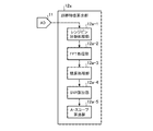
- the distance characteristic calculation unit 12a calculates the spectrum data and the A-scope data of the received signal of the laser beam. For example, the distance characteristic calculation unit 12a divides the received signal AD-converted by the AD conversion unit 11 into each range bin corresponding to the pulse width of the transmitted light, and executes FFT processing on the signal of each range bin. , Generate spectral data for each range bin. The distance characteristic calculation unit 12a integrates the spectrum data for each range bin in the spectrum space and calculates the peak value from the spectrum data of each range bin, whereby the distance and peak along the irradiation direction of the transmitted light from the laser radar device 1 A-scope data showing the correspondence with the value is calculated. The distance characteristic calculation unit 12a outputs the spectrum data and the A-scope data of each range bin to the signal processing switching unit 12b.
- the signal processing switching unit 12b outputs the integrated spectrum data and the A-scope data to either the moving speed calculation unit 12c or the HT position specifying unit 12d, so that the moving speed calculation unit 12c calculates the moving speed. And the HT position specifying process by the HT position specifying unit 12d are switched.
- the moving speed calculation unit 12c calculates the Doppler shift amount based on the peak frequency of the spectrum data of each range bin, and calculates the moving speed of the target for each range bin based on the Doppler shift amount.
- the HT position specifying unit 12d identifies the HT position based on the A-scope data, and based on the specified HT position, from the transmission light being transmitted from the telescope 6 to the reflection of the transmitted light in the HT. Calculate the time THT.
- Gate position setting unit 12e based on the time T HT calculated by HT position specifying unit 12d, generates a gate indicating the time and to output the received signal to the time and the AD conversion unit 11 to output to the amplifier 9b, produces The gate is set in the switch unit 9a.
- the trigger generation circuit 13 generates a trigger signal that pulses the light output from the optical distributor 3 to the pulse modulator 4, and sets the generated trigger signal in the gate position setting unit 12e to pulse the transmitted light. Control the time to change.
- the trigger generation circuit 13 generates a trigger signal based on a preset pulse width and pulse period.
- a pulse generator or a function generator is used for the trigger generation circuit 13 .
- the trigger generation circuit 13 is configured by using, for example, FPGA.
- the AD conversion of the received signal by the AD conversion unit 11 is performed using the trigger signal from the trigger generation circuit 13 as the start trigger.
- the start time of the AD conversion coincides with the timing at which the pulse of the transmitted light is transmitted, and the AD conversion is executed in a period corresponding to the pulse of the transmitted light and the interval between the pulses.
- the AD conversion unit 11 outputs a reception signal (digital signal) corresponding to the transmitted light for each pulse to the distance characteristic calculation unit 12a.
- FIG. 6 is a block diagram showing the configuration of the distance characteristic calculation unit 12a.
- the distance characteristic calculation unit 12a includes a range bin division processing unit 12a-1, an FFT processing unit 12a-2, an integration processing unit 12a-3, an SNR calculation unit 12a-4, and an A-scope calculation unit 12a. It is equipped with -5.
- the range bin division processing unit 12a-1 divides the received signal corresponding to the transmitted light for each pulse input from the AD conversion unit 11 at regular time width intervals.
- the division means that the received signal is associated with a section for each fixed time width.
- the transmitted light scattered or reflected by the targets existing at different distances (ranges) from the laser radar device 1 is used.
- the width of the range bin corresponds to the pulse width of the transmitted light, and the pulse width is a value preset in the laser radar device 1.
- the FFT processing unit 12a-2 performs FFT processing on the received signal divided for each range bin by the range bin division processing unit 12a-1 to generate spectrum data for each range bin.
- the optical system unit 5 transmits the transmitted light a plurality of times for each pulse, and receives the received light corresponding to each of the plurality of pulses.
- the FFT processing unit 12a-2 performs FFT processing on the received signals corresponding to each of the plurality of received lights and divided for each range bin.
- the integration processing unit 12a-3 integrates the spectrum data calculated for each range bin by the FFT processing unit 12a-2.
- the SNR calculation unit 12a-4 calculates the received SNR, which is the ratio of the received signal to the noise outside the used frequency band, using the peak intensity of the integrated spectrum of each range bin.
- the peak intensity is the spectral intensity corresponding to the position of the peak frequency in the spectrum. Further, the peak intensity may be the spectral intensity corresponding to the center of gravity frequency position obtained by performing the center of gravity calculation on the spectral data.
- the SNR calculation unit 12a-4 transfers the range bin information including the value of the label that identifies each range bin, the spectrum data integrated by the integration processing unit 12a-3, and the received SNR to the A-scope calculation unit 12a-5. Output.
- the A-scope calculation unit 12a-5 calculates the A-scope data using the received SNR calculated by the SNR calculation unit 12a-4.
- the A-scope data is data showing the distance characteristic of the received SNR.
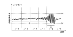
- FIG. 7 is a waveform diagram showing the waveform of the received signal in the first embodiment, and shows the time change of the received signal corresponding to the transmitted light for one pulse.
- n represents the label of the range bin in which the received signal is divided.
- the received signal having a small value of the label n corresponds to the light in which the transmitted light is scattered or reflected by the target existing in the vicinity of the laser radar device 1.
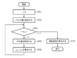
- FIG. 8 is a flowchart showing the operation of the laser radar device 1 according to the first embodiment.
- the value 0 is set in the parameter i (step ST1).
- the pulse width is set for the trigger generation circuit 13 (step ST2).
- the signal processing switching unit 12b confirms whether the value of the parameter i is 0 or 1 (step ST3).
- the signal processing switching unit 12b outputs the A-scope data calculated by the distance characteristic calculation unit 12a to the HT position specifying unit 12d.
- the HT position specifying unit 12d specifies the HT position based on the A-scope data and the detection limit value of the received SNR (step ST4).
- FIG. 9 is a diagram showing an outline of HT position identification processing using the A-scope of the received SNR.
- the A-scope D1 is A-scope data relating to the HT at a distance close to the laser radar device 1
- the A-scope D2 is the HT at a distance far from the laser radar device 1.
- the surface of the HT to be measured has undulations (unevenness) equal to or larger than the wavelength of the transmitted light, the coherency of the reflected light is reduced by reflecting the transmitted light in the HT. Further, when the light reflected by the transmitted light in the HT is scattered in the aerosol existing at a distance farther from the laser radar device 1 than the HT, the received SNR of the scattered light is lowered to the detection limit value SNR1.
- the HT position specifying unit 12d A- values of SNR in scope data, by up to monitor from the range R MAX to become closer direction to the laser radar apparatus 1 of the measurement, the received SNR is greater than the detection limit SNR1 specifying the distance (range bins) L HT.
- the HT position is a position separated from the laser radar device 1 by a distance L HT along the irradiation direction of the transmitted light.
- the laser beam reflected by the HT is discriminated from the laser beam received by the optical system unit 5.
- the distance L HT and the time T HT obtained by the HT position specifying unit 12d are output to the moving speed calculation unit 12c.
- the HT position specifying unit 12d sets the value 1 in the parameter i.
- the movement speed calculation unit 12c calculates the wind speed and the movement speed of the HT, which are the movement speeds of the aerosol, based on the information input from the signal processing switching unit 12b and the distance L HT and the time T HT input from the HT position specifying unit 12d. Calculate (step ST6).
- Trigger generating circuit 13 the time T 0 and the pulse width ⁇ t pulsing the transmission light is set to gate position setting section 12e as a trigger signal.
- the gate position setting unit 12e outputs the time T 0 , the time THT, and the pulse width ⁇ t to the switch unit 9a.
- a gate having a time width corresponding to the pulse width ⁇ t is set in the switch unit 9a.
- FIG. 10A is a waveform diagram showing the waveform of the received signal amplified by the amplifier 9b, and shows the waveform of the digital signal obtained by AD-converting the received signal amplified by the amplifier 9b.
- the strength of the received signal corresponding from the time T 0 to the time when the time THT has elapsed is amplified by the amplifier 9b.
- the reception signal is amplified without strength similarly saturation of the received signal after the time obtained by adding a pulse width ⁇ t worth of time to the time T HT, as indicated at C, which corresponds to the reflected light in the HT
- the reception signal after the time obtained by adding a pulse width ⁇ t worth of time to the time T HT, since not used in the wind measuring in space from the laser radar apparatus 1 to HT, may not be passed through the amplifier 9b.
- FIG. 10B is a waveform diagram showing a waveform of a received signal that has not been amplified by the amplifier 9b.
- the received signal corresponding from the time when the time THT has elapsed to the time after the time of the pulse width ⁇ t has elapsed is AD-converted.
- Moving speed computing unit 12c extracts the peak frequency f m from the spectral data after integration of each range bin, based on the difference between the frequency f IF of the extracted frequency f m and the beat signal, the Doppler shift amount ⁇ f for each range bin (N) is calculated.
- the moving speed of the HT is calculated based on.
- the received signal converted into a digital signal by the AD conversion unit 11 includes a signal that has passed through the amplifier 9b and a signal that has not passed through the amplifier 9b. Therefore, the moving speed calculation unit 12c calculates the moving speed of ST based on the received signal that has passed through the amplifier 9b at the distance L corresponding to one range bin, and HT is based on the received signal that does not pass through the amplifier 9b. Calculate the moving speed of. That is, the moving speed corresponding to each of the two received signals is calculated.
- the distance characteristic calculation unit 12a determines the moving speed of the target based on a single system of received signals generated by trimming and combining the signals in the time domain used for ST measurement and HT measurement from the received signals. It may be calculated.
- FIG. 10C is a waveform diagram showing a waveform of a received signal that has been subjected to saturation suppression processing.
- the moving speed calculation unit 12c can measure ST and HT by using the signal shown in FIG. 10C.
- the measurement of the HT existing in the measurement target space and the measurement of the ST existing up to the HT in the measurement target space are performed.
- the laser light reflected by the HT is discriminated from the received laser beam, and the intensity of the received signal of the discriminated laser beam is controlled so as not to be saturated.
- the laser radar device 1 can perform both HT measurement and ST measurement while suppressing a decrease in HT measurement accuracy.
- the intensity control unit 10 includes a switch unit 9a and an amplifier 9b.
- the switch unit 9a does not amplify the intensity of the received signal of the laser light reflected by the HT 100 by the amplifier 9b, but amplifies the intensity of the received signal of the laser light scattered in the ST 101 by the amplifier 9b. As a result, the intensity of the received signal of the laser beam reflected by the HT 100 is changed to an intensity that does not saturate.
- FIG. 11 is a block diagram showing a configuration of the laser radar device 1A according to the second embodiment.
- the laser radar device 1A includes a light source 2, an optical distributor 3, a pulse modulator 4, an optical system unit 5, a telescope 6, an optical coupler 7, a light receiving unit 8, an intensity control unit 10A, an AD conversion unit 11, and a signal processing unit 12. And a trigger generation circuit 13.
- the intensity control unit 10A includes an optical variable attenuator 14 and a gain setting unit 15.
- the same components as those in FIG. 5 are designated by the same reference numerals, and the description thereof will be omitted.
- the intensity control unit 10A attenuates the intensity of the laser beam reflected by the HT 100 so that the intensity of the received signal of the laser beam is not saturated.
- the optical variable attenuator 14 is an attenuation unit that attenuates the intensity of the optical signal according to the gain (attenuation amount) set by the gain setting unit 15.
- the optical variable attenuator 14 may be a fiber type or a spatial type.
- the spatial variable optical attenuator 14 has filters having different optical densities (OD) arranged on the optical axis.
- some optical variable attenuators 14 use a wedge prism to shift the optical axis position or the optical axis angle of the optical coupler 7 and the light receiving unit 8.
- the gain setting unit 15 is a setting unit that sets the gain (attenuation amount) according to the gate position set by the gate position setting unit 12e to the optical variable attenuator 14.
- the gate position is information indicating the time for attenuating the intensity of the optical signal and the time width thereof.
- the light receiving unit 8 converts the received light whose intensity has not been attenuated by the light variable attenuator 14 into an electric signal, and the amplifier 9b amplifies the intensity of the received signal converted into an electric signal by the light receiving unit 8.
- the AD conversion unit 11 converts the received signal amplified by the amplifier 9b into a digital signal. Of the received signals AD-converted by the AD conversion unit 11, the signals in the time domain corresponding to the laser light reflected by the HT are amplified and saturated by the amplifier 9b.
- the distance characteristic calculation unit 12a divides the received signal AD-converted by the AD conversion unit 11 into each range bin corresponding to the pulse width of the transmitted light, and performs FFT processing on the signal of each range bin to perform FFT processing for each range bin. Generate spectral data for. Then, the distance characteristic calculation unit 12a integrates the spectrum data for each range bin in the spectrum space and calculates the peak value from the spectrum data of each range bin, so that the distance along the irradiation direction of the transmitted light from the laser radar device 1A A-scope data showing the correspondence between the peak value and the peak value is calculated.
- the HT position specifying unit 12d is calculated by the distance characteristic calculating unit 12a A- values of SNR in scope data, by monitoring the maximum range R MAX measuring the near becomes direction to the laser radar apparatus 1, the received SNR There identifies the distance L HT larger than the detection limit value SNR1.
- the HT position is a position separated from the laser radar device 1A by a distance L HT along the irradiation direction of the transmitted light.
- Trigger generating circuit 13 the time T 0 and the pulse width ⁇ t pulsing the transmission light is set to gate position setting section 12e as a trigger signal.
- the gate position setting unit 12e sets the time T 0 , the time THT, and the pulse width ⁇ t in the gain setting unit 15.
- Gain setting unit 15 an optical signal corresponding to the received signal after the time obtained by adding a pulse width ⁇ t worth of time to the optical signal and time T HT corresponding to the received signal from time T 0 to time T time HT has passed
- the gain at which the amount of attenuation becomes 0 is set in the optical variable attenuator 14 so that the attenuation is not attenuated.
- a received signal having a waveform as shown in FIGS. 10A and 10B can be obtained.
- Moving speed computing unit 12c based on the received signal from time T 0 to time T time HT has elapsed, it calculates the moving velocity of the aerosol which is present in the space from the laser radar apparatus 1 to HT (wind speed), the time based on the received signal corresponding to the T HT to time the pulse width ⁇ t worth of time has elapsed, it calculates the moving speed of the HT.
- the intensity control unit 10A has an optical variable attenuator 14 that attenuates the intensity of the laser beam and a gain setting unit 15 that sets the attenuation amount in the optical variable attenuator 14. And.
- the light variable attenuator 14 does not attenuate the intensity of the laser light scattered in the ST, but attenuates the intensity of the laser light reflected in the HT. Since the intensity of the received signal of the laser beam reflected by the HT 100 is controlled so as not to be saturated, the laser radar device 1A performs both HT measurement and ST measurement while suppressing a decrease in HT measurement accuracy. It can be carried out. Further, since the intensity of the received light in the previous stage of being input to the light receiving unit 8 is controlled, the AD conversion unit 11 shown in FIG. 11 may have one input channel. Therefore, the configuration of the laser radar device 1A is simplified.
- the laser radar device according to the present invention can be used, for example, as a laser radar device that measures various targets.
- 1,1A laser radar device 2 light source, 3 optical distributor, 4 pulse modulator, 5 optical system unit, 5a transmission side optical system, 5b transmission / reception separation unit, 5c reception side optical system, 6 telescope, 7 optical coupler, 8 light receiving unit, 9a switch unit, 9b amplifier, 10,10A intensity control unit, 11 AD conversion unit, 12 signal processing unit, 12a distance characteristic calculation unit, 12a-1 range bin division processing unit, 12a-2 FFT processing unit, 12a -3 Integration processing unit, 12a-4 SNR calculation unit, 12a-5 A-scope calculation unit, 12b signal processing switching unit, 12c movement speed calculation unit, 12d HT position identification unit, 12e gate position setting unit, 13 trigger generation circuit , 14 Optical variable attenuator, 15 Gain setting unit.
Landscapes
- Physics & Mathematics (AREA)
- Engineering & Computer Science (AREA)
- Electromagnetism (AREA)
- Computer Networks & Wireless Communication (AREA)
- General Physics & Mathematics (AREA)
- Radar, Positioning & Navigation (AREA)
- Remote Sensing (AREA)
- Optical Radar Systems And Details Thereof (AREA)
Abstract
レーザレーダ装置(1)は、測定対象空間に存在するHT(100)の計測および測定対象空間におけるHT(100)までの間に存在するST(101)の計測を行い、レーザ光の照射方向の距離とレーザ光の受信信号のSNRとの対応関係を示すデータおよびSNRの検出限界値に基づいて、受光されたレーザ光からHT(100)において反射されたレーザ光を判別し、判別されたレーザ光の受信信号の強度が飽和しないように制御する。
Description
本発明は、レーザレーダ装置に関する。
レーザ光を用いて風速を計測するレーザレーダ装置は、パルス状のレーザ光を大気中に照射し、大気中に存在するエアロゾルにおいて散乱したレーザ光の散乱光を受光することによって、エアロゾルの移動に伴った散乱光のドップラシフトを求め、散乱光のドップラシフトに基づいてレーザ照射方向の風速を計測する。
また、レーザレーダ装置には、エアロゾルのようなソフトターゲット(ST)以外に、ハードターゲット(HT)を計測するものがある。HTは、エアロゾルよりも格段に大きくかつ光学的に厚く透過率が極めて低いターゲットである。HTには、車両、航空機または船舶などの移動体がある。
HTを計測するレーザレーダ装置において、遠距離に存在するHTの検出を基準としてレーザ光の強度を高くした場合、近距離に存在するHTの検出に際して、レーザ光の強度が過大となる。レーザレーダ装置は、近距離に存在するHTにおいて反射したレーザ光の反射光を受光すると、当該反射光の受信信号の強度が飽和することにより計測値に誤差が発生する。
例えば、特許文献1には、遠距離に照射するレーザ光の透過率を高くし、近距離に照射するレーザ光の透過率を低くするレーザレーダ装置が記載されている。当該レーザレーダ装置においては、遠距離に存在する物体(HT)の検出を基準として、レーザ光の強度が高くされた場合であっても、近距離に存在する物体(HT)を検出するためのレーザ光の強度は減衰される。
従来のレーザレーダ装置において、HTまでの空間に照射されたレーザ光のエアロゾルにおける散乱光の強度は極めて小さく当該散乱光の受信信号の強度も極めて小さい。これに対して、HTは光学的に厚く透過率が極めて低いターゲットであるので、HTが遠距離に存在しても、HTにおける散乱光の強度は、エアロゾルにおける散乱光に比べて格段に大きい。
特許文献1に記載されるレーザレーダ装置では、遠距離に照射するレーザ光の透過率が高く設定され、近距離に照射するレーザ光の透過率が低く設定される。このため、HTの計測とSTの計測との両方を行う場合、遠方に存在するHTにおける散乱光の受信信号の強度が飽和することにより、HTの計測精度が低下するという課題があった。
本発明は上記課題を解決するものであり、HTの計測精度の低下を抑制しつつ、HTの計測とSTの計測の両方を行うことができるレーザレーダ装置を得ることを目的とする。
本発明に係るレーザレーダ装置は、レーザ光を測定対象空間へ照射し、測定対象空間で散乱または反射されたレーザ光を受光する光学系部と、光学系部によって受光されたレーザ光の受信信号の強度を制御する強度制御部と、測定対象空間に存在するHTの計測および測定対象空間におけるHTまでの間に存在するSTの計測を行う信号処理部とを備え、信号処理部は、レーザ光の照射方向の距離とレーザ光の受信信号の信号対雑音比(SNR)との対応関係を示すデータおよびSNRの検出限界値に基づいて、光学系部によって受光されたレーザ光からHTにおいて反射されたレーザ光を判別し、強度制御部は、信号処理部によって判別されたレーザ光の受信信号の強度が飽和しないように制御する。
本発明によれば、測定対象空間に存在するHTの計測および測定対象空間におけるHTまでの間に存在するSTの計測が行われる。レーザ光の照射方向の距離とレーザ光の受信信号のSNRとの対応関係を示すデータおよびSNRの検出限界値に基づいて、受光されたレーザ光から、HTにおいて反射されたレーザ光を判別し、判別されたレーザ光の受信信号の強度が飽和しないように制御される。これにより、本発明に係るレーザレーダ装置は、HTの計測精度の低下を抑制しつつ、HTの計測とSTの計測との両方を行うことができる。
実施の形態1.
図1は、実施の形態1に係るレーザレーダ装置1から照射されたレーザ光Aの散乱光の発生の概要を示す説明図である。レーザレーダ装置1による風計測において、パルス状のレーザ光Aが大気中に照射され、エアロゾルにおける散乱光s1が受光される。レーザ光Aのローカル光である単一周波数の連続光と散乱光s1とのヘテロダイン検波によって、エアロゾルの移動によって生じるドップラシフトが算出され、レーザ光の照射方向(視線方向)に沿った風速が計測される。
図1は、実施の形態1に係るレーザレーダ装置1から照射されたレーザ光Aの散乱光の発生の概要を示す説明図である。レーザレーダ装置1による風計測において、パルス状のレーザ光Aが大気中に照射され、エアロゾルにおける散乱光s1が受光される。レーザ光Aのローカル光である単一周波数の連続光と散乱光s1とのヘテロダイン検波によって、エアロゾルの移動によって生じるドップラシフトが算出され、レーザ光の照射方向(視線方向)に沿った風速が計測される。
レーザ光Aは、ローカル光に対して周波数変調されている。このため、ヘテロダイン検波における散乱光s1とローカル光との干渉によって、中間周波数であるビート周波数の信号が生成される。ビート周波数の信号はビート信号である。エアロゾルが移動すると、このビート周波数にドップラシフトが付加される。ドップラシフトは、ヘテロダイン検波が施された信号をフーリエ変換することで得られるスペクトルから算出される。風速を計測する方向は、レーザ光の出射方向を切り替えることによって変更される。
風計測において、ソフトターゲット(ST)であるエアロゾルが3次元的なボリュームターゲットとして扱われるのに対して、ハードターゲット(HT)100の計測においては、HT100が2次元的なターゲットとして扱われる。HT100の移動によって生じるドップラシフトに基づいて、HT100の移動速度が算出される。レーザレーダ装置1は、レーザレーダ装置1からHT100までの間に存在するSTであるエアロゾルを検出することによる風計測とHT100の計測とを同時に行う。HT100は、例えば、海面であってもよい。
HT100の計測とは、レーザレーダ装置1からHT100までの距離を測定しつつ、HT100の移動速度を測定することを意味する。また、コヒーレント方式による風計測においては、図1に示すように、大気中のエアロゾルにおいてレーザ光Aが散乱した散乱光s1の受信信号が計測に用いられる。散乱光s1の強度は、一般に極めて小さく、散乱光s1の受信信号の強度も極めて小さい。さらに、散乱光s1とローカル光を干渉させることで発生するビート信号の振幅も同様に小さい。
散乱光s1の受信信号に対応するビート信号は、AD変換が行われる前に、雑音を抑制しつつ振幅を増加させることにより、SNRの向上を図ることができる。HT100は、固体、液体もしくは光学的に厚く透過率の極めて低いボリュームターゲットであるため、HT100においてレーザ光Aが反射した反射光s2の強度は大きく、反射光s2の受信信号の強度も極めて大きい。これにより、エアロゾルの計測とHT100の計測とが同時に行われる場合、反射光s2の受信信号が飽和する。
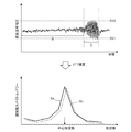
図2は、HTにおける反射光の受信信号の強度の飽和およびHTの計測誤差の概要を示す図である。図2の上側図は、レーザレーダ装置1から照射されたレーザ光が、STであるエアロゾルにおいて散乱されHTにおいて反射され、レーザレーダ装置1によって散乱光および反射光が受信された受信信号の波形を示す波形図である。この波形図において、SV1は、受信信号電圧の下限値であり、SV2は、受信信号電圧の上限値である。すなわち、受信信号の電圧が上限値SV2を超えた場合には、受信信号の強度が飽和した状態となる。図2の下側図は、積算スペクトルSaまたはSbを示す波形図である。積算スペクトルは、一定の時間のレンジビンごとの受信信号(ビート信号)に高速フーリエ変換(FFT)を施して得られた複数のスペクトルが積算されたものである。
ビート信号の電圧が上限値SV2を超えてビート信号が飽和している場合、ビート信号にFFTを施したスペクトルSaの周波数帯域内には、偽信号が重畳される。飽和がないビート信号にFFTが実行されたスペクトルSbとスペクトルSaとの間には、図2の下側図に示すように、周波数ずれが生じる。ターゲットの移動速度は、ドップラシフト量に基づいて算出され、ドップラシフト量は、ビート信号にFFTが実行されたスペクトルのピーク周波数(中心周波数)のシフトである。このため、受信信号の強度が飽和すると、ドップラシフト量に誤差が生じ、ターゲットの移動速度にも誤差が生じる。
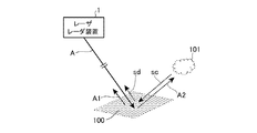
図3は、レーザレーダ装置1によるHT100の計測およびST101の計測の概要を示す説明図である。レーザレーダ装置1は、HT100において反射したレーザ光に生じるコヒーレンシの低下を検出することによって、受光されたレーザ光のうち、HT100において反射したレーザ光を判別する。HT100が理想的な正反射面であると仮定した場合、レーザレーダ装置1から照射されたレーザ光Aのうち、HT100において正反射したレーザ光A1は、大気中を伝搬してから、レーザレーダ装置1によって受光される。
HT100において正反射したレーザ光A2は、図3に示すように、ST101であるエアロゾルにおいて散乱されることによって散乱光Scとなる。HT100において散乱光Scが正反射した反射光Sdは、大気中を伝搬してから、レーザレーダ装置1によって受光される。しかしながら、HT100の反射面は、理想的な正反射面とはならず、反射面の凹凸は、レーザ光Aの波長に対して十分に大きい場合が多い。
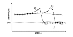
図4は、レーザレーダ装置1における受信SNRのA-スコープを示す図である。図4において、受信SNRのA-スコープは、レーザレーダ装置1からのレーザ光Aの照射方向の距離とレーザレーダ装置1によるレーザ光Aの受信信号のSNRとの対応関係を示すデータである。また、A-スコープD1は、レーザレーダ装置1に近い距離にあるHTに関するA-スコープデータであり、A-スコープD2は、レーザレーダ装置1から遠い距離にあるHTに関するA-スコープデータである。
HT100の反射面の凹凸がレーザ光Aの波長に対して十分に大きい場合、HT100の反射面において反射されたレーザ光Aは、その波面に乱れが生じてコヒーレンシが低下する。HT100の反射面において反射された反射光のコヒーレンシが低下すると、ST101において散乱された散乱光Scのコヒーレンシも低下する。散乱光Scは、図3に示したように、HT100よりもレーザレーダ装置1から遠い距離に存在するST101における散乱光である。
A-スコープD1およびA-スコープD2において、符号Eで示すように、散乱光Scのコヒーレンシの低下に伴い、HT100よりもレーザレーダ装置1から遠い距離に存在するST101における散乱光Scの受信SNR(信号対雑音比)は、検出限界値SNR1まで低下する。レーザレーダ装置1は、散乱光Scの受信SNRが検出限界値SNR1まで低下するという特性を利用して、受光されたレーザ光から、HT100において反射したレーザ光を判別する。
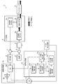
図5は、実施の形態1に係るレーザレーダ装置1の構成を示すブロック図である。図5において、レーザレーダ装置1は、光源2、光分配器3、パルス変調器4、光学系部5、テレスコープ6、光カプラ7、受光部8、強度制御部10、AD変換部11、信号処理部12およびトリガ生成回路13を備える。光学系部5は、送信側光学系5a、送受分離部5bおよび受信側光学系5cを備える。強度制御部10は、スイッチ部9aおよびアンプ9bを備える。信号処理部12は、距離特性算出部12a、信号処理切替部12b、移動速度算出部12c、HT位置特定部12dおよびゲート位置設定部12eを備える。
光源2は、単一周波数からなる連続光を出力する光源であり、光分配器3に接続されている。光分配器3は、光源2から出力された光を2分割し、分割された一方の光をパルス変調器4に出力し、他方の光を光カプラ7に出力する。光分配器3には、例えば、1:2ファイバカプラが用いられる。また、光分配器3には、ハーフミラーを用いて構成されるものもある。
パルス変調器4は、光分配器3を介して光源2から入力された光をパルス変調し、パルス変調された光信号を周波数シフトさせることで、送信光を生成する。送信光は、レーザレーダ装置1から測定対象空間へ照射されるパルス状のレーザ光である。送信光は、光学系部5に出力される。パルス変調器4には、例えば、音響光学変調器(AOM)が用いられる。
送信側光学系5aは、パルス変調器4から入力した送信光のビーム径とビーム広がり角を整形し、ビーム径およびビーム広がり角が整形された送信光を、送受分離部5bへ出力する。送信側光学系5aは、例えば、凹面レンズと凸面レンズを含むレンズ群を用いて構成される。また、送信側光学系5aは、ミラーを用いた反射型の光学系であってもよい。
送受分離部5bは、送信側光学系5aとテレスコープ6との間で、かつ送信光の光軸上に設けられ、送信光をテレスコープ6へ出力するとともに、テレスコープ6からの受信光を受信側光学系5cへ出力する。送受分離部5bには、サーキュレータまたは偏光ビームスプリッタ(PBS)を用いることができる。
受信側光学系5cは、受信光のビーム径とビーム広がり角を整形し、ビーム径およびビーム広がり角が整形された受信光を、光カプラ7へ出力する。受信光は、測定対象空間において送信光が散乱または反射された散乱光または反射光である。受信側光学系5cは、例えば、凹面レンズと凸面レンズを含むレンズ群を用いて構成される。また、受信側光学系5cは、ミラーを用いた反射型の光学系であってもよい。
テレスコープ6は、送受分離部5bから入力した送信光を測定対象空間へ照射するとともに、測定対象空間からの受信光を受光する。テレスコープ6は、例えば、凹面レンズと凸面レンズを含むレンズ群を用いて構成される。また、テレスコープ6は、ミラーを用いた反射型の光学系であってもよい。
光カプラ7は、光分配器3から入力した光と、受信側光学系5cから入力した受信光とを合波し、合波した光を受光部8へ出力する。光カプラ7によって合波された光信号が、ビート信号である。光カプラ7には、ファイバ型のコンバイナが利用可能である。光カプラ7によって合波された光信号は、周波数シフトfIF(中心周波数)に対応するビート信号である。受信光において、風速およびHTの移動に対応したドップラシフト周波数が生じている場合、ビート信号の周波数は中心周波数fIFにドップラシフト周波数Δfを加えた値となる。
受光部8は、例えば、バランスドレシーバであり、光カプラ7から入力したビート信号を電気信号に変換し、電気信号のビート信号(受信信号)をスイッチ部9aへ出力する。強度制御部10は、光学系部5によって受光された受信光の受信信号の強度を制御する。スイッチ部9aは、ゲート位置設定部12eによって設定されたゲート位置情報に基づいて、受光部8から入力した受信信号を、アンプ9bへ出力する経路と、AD変換部11へ出力する経路とを切り替える。アンプ9bは、スイッチ部9aを介して入力した受信信号の強度を増幅させる増幅部である。アンプ9bによって増幅された受信信号は、AD変換部11へ出力される。
AD変換部11は、強度制御部10を介して受信信号を入力し、入力した受信信号を、デジタル信号へ変換する。AD変換部11によってAD変換された受信信号は、信号処理部12へ出力される。図5に示すAD変換部11は、アンプ9bを通過した信号とアンプ9bを通過しない信号とを入力する、2チャンネルのAD変換器である。ただし、アンプ9bを通過した信号とアンプ9bを通過しない信号を、アナログマルチプレクサによって束ねることで、AD変換部11には、1チャンネルのAD変換器を用いることができる。
信号処理部12は、例えば、FPGA(Field Programmable Gate Array)を用いて構成される。信号処理部12において、距離特性算出部12a、信号処理切替部12b、移動速度算出部12c、HT位置特定部12dおよびゲート位置設定部12eは、デジタル信号およびTTL(Transistor-Transistor-Logic)信号を用いて、指示またはデータのやり取りが行われる。
距離特性算出部12aは、レーザ光の受信信号のスペクトルデータおよびA-スコープデータを算出する。例えば、距離特性算出部12aは、AD変換部11によってAD変換された受信信号を、送信光のパルス幅に対応するレンジビンごとに分割し、各レンジビンの信号に対してFFT処理を実行することで、レンジビンごとのスペクトルデータを生成する。距離特性算出部12aは、レンジビンごとのスペクトルデータをスペクトル空間で積算し、各レンジビンのスペクトルデータからピーク値を算出することで、レーザレーダ装置1からの送信光の照射方向に沿った距離とピーク値との対応関係を示すA-スコープデータを算出する。距離特性算出部12aは、各レンジビンのスペクトルデータおよびA-スコープデータを信号処理切替部12bへ出力する。
信号処理切替部12bは、積算されたスペクトルデータおよびA-スコープデータを、移動速度算出部12cまたはHT位置特定部12dのいずれかに出力することで、移動速度算出部12cによる移動速度の算出処理とHT位置特定部12dによるHT位置の特定処理とを切り替える。
移動速度算出部12cは、各レンジビンのスペクトルデータのピーク周波数に基づいてドップラシフト量を算出し、ドップラシフト量に基づいてレンジビンごとのターゲットの移動速度を算出する。HT位置特定部12dは、A-スコープデータに基づいてHT位置を特定し、特定したHT位置に基づいて、テレスコープ6から送信光が送信されてから、HTにおいて送信光が反射されるまでの時間THTを算出する。ゲート位置設定部12eは、HT位置特定部12dによって算出された時間THTに基づいて、受信信号をアンプ9bへ出力させる時間とAD変換部11へ出力させる時間とを示すゲートを生成し、生成したゲートをスイッチ部9aに設定する。
トリガ生成回路13は、光分配器3からパルス変調器4へ出力された光をパルス化するトリガ信号を生成し、生成したトリガ信号をゲート位置設定部12eに設定することで、送信光をパルス化する時間を制御する。トリガ生成回路13は、予め設定されたパルス幅およびパルス周期に基づいてトリガ信号を生成する。トリガ生成回路13には、例えば、パルスジェネレータまたはファンクションジェネレータが用いられる。また、トリガ生成回路13は、例えば、FPGAを用いて構成される。
また、AD変換部11による受信信号のAD変換は、トリガ生成回路13からのトリガ信号を開始トリガとして行われる。AD変換の開始時刻は、送信光のパルスが送信されたタイミングに一致し、送信光のパルスとパルスの間隔に対応する期間においてAD変換が実行される。AD変換部11によるAD変換が開始されてから時間Δt(=2L/c)が経過した後にAD変換された信号は、レーザレーダ装置1から距離Lだけ離れた位置に存在するターゲット(例えば、ST101またはHT100)において散乱または反射された送信光に対応する受信信号である。cは光速である。AD変換部11は、1パルスごとの送信光に対応する受信信号(デジタル信号)を、距離特性算出部12aへ出力する。
図6は、距離特性算出部12aの構成を示すブロック図である。距離特性算出部12aは、図6に示すように、レンジビン分割処理部12a-1、FFT処理部12a-2、積算処理部12a-3、SNR算出部12a-4、およびA-スコープ算出部12a-5を備える。
レンジビン分割処理部12a-1は、AD変換部11から入力した1パルスごとの送信光に対応する受信信号を、一定の時間幅ごとに分割する。ここで、分割とは、受信信号を一定の時間幅ごとの区間に対応付けることを意味する。また、送信光の1パルス分に対応する受信信号を一定の時間幅ごとに分割する処理は、レーザレーダ装置1から互いに異なる距離(レンジ)にそれぞれ存在するターゲットにおいて散乱または反射された送信光を分離する処理に相当する。レンジビンの幅は、送信光のパルス幅に相当し、パルス幅は、レーザレーダ装置1に予め設定された値である。
FFT処理部12a-2は、レンジビン分割処理部12a-1によってレンジビンごとに分割された受信信号に対してFFT処理を行い、レンジビンごとのスペクトルデータを生成する。光学系部5によって、パルスごとに送信光が複数回送信され、複数のパルスのそれぞれに対応する受信光が受信される。FFT処理部12a-2は、複数の受信光のそれぞれに対応しかつレンジビンごとに分割された受信信号に対してFFT処理を行う。
積算処理部12a-3は、FFT処理部12a-2によってレンジビンごとに算出されたスペクトルデータを積算する。SNR算出部12a-4は、各レンジビンの積算されたスペクトルのピーク強度を用いて、受信信号と使用周波数帯域外の雑音との比である受信SNRを算出する。なお、ピーク強度は、スペクトルにおけるピーク周波数の位置に対応するスペクトル強度である。また、ピーク強度は、スペクトルデータに重心演算を施して得られる重心周波数位置に対応するスペクトル強度であってもよい。
SNR算出部12a-4は、個々のレンジビンを特定するラベルの値を含むレンジビン情報と、積算処理部12a-3によって積算されたスペクトルデータと、受信SNRを、A-スコープ算出部12a-5へ出力する。A-スコープ算出部12a-5は、SNR算出部12a-4によって算出された受信SNRを用いてA-スコープデータを算出する。A-スコープデータは、受信SNRの距離特性を示すデータである。
図7は、実施の形態1における受信信号の波形を示す波形図であり、1パルス分の送信光に対応する受信信号の時間変化を示している。nは、受信信号が分割されたレンジビンのラベルを表している。ラベルnの値が小さい受信信号は、レーザレーダ装置1の近傍に存在するターゲットにおいて送信光が散乱または反射された光に対応している。
符号Bで示す区間(ラベルn=1~4)の受信信号は、レーザレーダ装置1からHTまでの間に存在するエアロゾルにおいて送信光が散乱した光に対応している。また、符号Cで示す区間(ラベルn=5)の受信信号は、HTにおいて送信光が反射した光に対応している。HTはレーザレーダ装置1から遠い位置に存在するが、HTにおいて送信光が反射した光に対応する受信信号の強度は、図7に示すように、上限値SV2を超えて飽和している。
A-スコープ算出部12a-5は、レンジビン情報(ラベルnを含む情報)、レンジビン幅Δtおよび光速cを用いて、レーザレーダ装置1からターゲットが存在する位置までの距離L(=c×Δt/2)をレンジビンごとに算出し、算出した距離Lと受信SNRとの対応関係を示すA-スコープデータを算出する。これにより、図4に示したようなA-スコープデータが得られる。
図8は、実施の形態1に係るレーザレーダ装置1の動作を示すフローチャートである。レーザレーダ装置1によるターゲットの計測が開始されると、パラメータiに値0が設定される(ステップST1)。トリガ生成回路13に対してパルス幅が設定される(ステップST2)。これにより、前述したA-スコープデータの算出までの処理が実行される。次に、信号処理切替部12bは、パラメータiの値が0であるか1であるかを確認する(ステップST3)。
パラメータiの値が0である場合(ステップST3;i=0)、レーザレーダ装置1によるターゲットの計測が開始されてHT位置が特定される前の段階である。信号処理切替部12bは、距離特性算出部12aによって算出されたA-スコープデータを、HT位置特定部12dに出力する。
HT位置特定部12dは、A-スコープデータと受信SNRの検出限界値に基づいて、HT位置を特定する(ステップST4)。図9は、受信SNRのA-スコープを利用したHT位置の特定処理の概要を示す図である。図9において、A-スコープD1は、図4と同様に、レーザレーダ装置1に近い距離にあるHTに関するA-スコープデータであり、A-スコープD2は、レーザレーダ装置1から遠い距離にあるHTに関するA-スコープデータである。
計測対象のHTの表面には送信光の波長以上の起伏(凹凸)があるので、送信光がHTにおいて反射することで、反射光のコヒーレンシは低下する。さらに、HTにおいて送信光が反射した光が、HTよりもレーザレーダ装置1から遠い距離に存在するエアロゾルにおいて散乱すると、この散乱光の受信SNRは検出限界値SNR1まで低下する。
HT位置特定部12dは、A-スコープデータにおける受信SNRの値を、測定の最大レンジRMAXからレーザレーダ装置1に近くなる方向へモニタすることで、受信SNRが検出限界値SNR1よりも大きくなる距離(レンジビン)LHTを特定する。レーザレーダ装置1から送信光の照射方向に沿って距離LHTだけ離れた位置が、HT位置である。HT位置特定部12dは、距離LHTおよび光速cを用いて、HTにおいて送信光が反射された時間THT(=2LHT/c)を算出する(ステップST5)。
例えば、A-スコープD1において、距離LHT1が特定され、時間THT1(=2LHT1/c)が算出される。A-スコープD2において、距離LHT2が特定され、時間THT2(=2LHT2/c)が算出される。これにより、光学系部5によって受光されたレーザ光から、HTにおいて反射されたレーザ光が判別される。HT位置特定部12dによって求められた距離LHTおよび時間THTは、移動速度算出部12cへ出力される。HT位置特定部12dは、パラメータiに値1を設定する。
ステップST5の処理が完了すると、図8に示す一連の処理は、ステップST3の処理に戻る。パラメータiの値が1であるので(ステップST3;i=1)、信号処理切替部12bは、レンジビン情報、積算されたスペクトルデータおよびA-スコープデータを、移動速度算出部12cへ出力する。移動速度算出部12cは、信号処理切替部12bから入力した情報と、HT位置特定部12dから入力した距離LHTおよび時間THTに基づいて、エアロゾルの移動速度である風速とHTの移動速度を算出する(ステップST6)。
トリガ生成回路13は、送信光をパルス化する時刻T0およびパルス幅Δtを、トリガ信号としてゲート位置設定部12eに設定する。ゲート位置設定部12eは、時刻T0と時刻THTとパルス幅Δtをスイッチ部9aへ出力する。スイッチ部9aには、パルス幅Δtに対応する時間幅のゲートが設定される。スイッチ部9aは、時刻T0から時間THTが経過した時刻までの受信信号と、時間THTにパルス幅Δt分の時間を加えた時刻以降の受信信号を、パルス幅Δtごとにアンプ9bへ出力する。
図10Aは、アンプ9bによって増幅された受信信号の波形を示す波形図であり、アンプ9bによって増幅された受信信号がAD変換されたデジタル信号の波形を示している。時刻T0から時間THTが経過した時刻までに対応する受信信号の強度が、アンプ9bによって増幅される。これにより、レーザレーダ装置1からHTまでの空間に存在するST(エアロゾル)における散乱光に対応する受信信号(ラベルn=1~4)の強度が飽和せずに増幅される。
また、時間THTにパルス幅Δt分の時間を加えた時刻以降の受信信号の強度も同様に飽和せずに増幅されるが、符号Cで示すように、HTにおける反射光に対応する受信信号(ラベルn=5)の強度は飽和する。なお、時間THTにパルス幅Δt分の時間を加えた時刻以降の受信信号は、レーザレーダ装置1からHTまでの空間における風計測に用いられないので、アンプ9bを通過させなくてもよい。
また、スイッチ部9aは、時間THTからパルス幅Δt分の時間が経過した時刻までに対応する受信信号を、アンプ9bを通過せずにAD変換部11へ出力する。図10Bは、アンプ9bによって増幅されていない受信信号の波形を示す波形図である。時間THTが経過した時刻からパルス幅Δt分の時間が経過した後の時刻までに対応する受信信号が、AD変換される。これにより、図10Bに示すように、HTにおける反射光に対応する、飽和していない受信信号(ラベルn=5)がデジタル信号に変換される。
移動速度算出部12cは、各レンジビンの積算後のスペクトルデータからピーク周波数fmを抽出し、抽出した周波数fmとビート信号の周波数fIFとの差に基づいて、レンジビンごとのドップラシフト量Δf(n)を算出する。移動速度算出部12cは、送信光の波長λとドップラシフト量Δf(n)とを用いて、ターゲットの移動速度v(n)(=λ×Δf(n)/2)をレンジビンごとに算出する。これにより、ラベルn=1~4に対応する受信信号に基づいて、レーザレーダ装置1からHTまでの空間に存在するエアロゾルの移動速度(風速)が算出され、ラベルn=5に対応する受信信号に基づいて、HTの移動速度が算出される。
AD変換部11によってデジタル信号に変換された受信信号は、アンプ9bを通過させたものと、アンプ9bを通過させないものがある。このため、移動速度算出部12cは、1つのレンジビンに対応する距離Lにおいて、アンプ9bを通過させた受信信号に基づいてSTの移動速度を算出し、アンプ9bを通過させない受信信号に基づいてHTの移動速度を算出する。すなわち、二系統の受信信号のそれぞれに応じた移動速度が算出される。
なお、レーザレーダ装置1からHTまでの空間に存在するエアロゾルの移動速度(風速)の算出処理において、アンプ9bを通過させない時間領域の受信信号は不要であり、HTの移動速度の算出処理において、アンプ9bを通過させる時間領域の受信信号は不要である。そこで、距離特性算出部12aは、受信信号からSTの計測とHTの計測に用いられる時間領域の信号をトリミングして結合して生成された一系統の受信信号に基づいて、ターゲットの移動速度を算出してもよい。
図10Cは、飽和抑制処理が施された受信信号の波形を示す波形図である。図10Cに示す受信信号は、アンプ9bを通過させた受信信号における符号Fで示す時間領域の信号(ラベルn=5)を、アンプ9bを通過させなかった受信信号における同一の時間領域の信号で置き換えたものである。例えば、距離特性算出部12aが、アンプ9bを通過させなかった受信信号におけるラベルn=5に対応する時間領域の信号をトリミングし、トリミングした信号を、アンプ9bを通過させなかった受信信号における、同一の時間領域の信号に対して結合する。これにより、図10Cに示す信号が生成される。
ラベルn=5に対応する時間領域の信号は、HTからの反射光に対応した信号であり、アンプ9bを通過すると強度が飽和する。これに対し、図10Cに示す信号においては、ラベルn=5に対応する時間領域の信号が、アンプ9bを通過させなかった受信信号における、飽和していない同一の時間領域の信号に置き換えられている。これにより、時間領域ごとの信号強度の飽和が抑制される。移動速度算出部12cは、図10Cに示す信号を用いることで、STの計測とHTの計測を行うことができる。
以上のように、実施の形態1に係るレーザレーダ装置1において、測定対象空間に存在するHTの計測および測定対象空間におけるHTまでの間に存在するSTの計測が行われる。A-スコープデータおよび受信SNRの検出限界値に基づいて、受光されたレーザ光から、HTにおいて反射されたレーザ光が判別され、判別されたレーザ光の受信信号の強度が飽和しないように制御される。これにより、レーザレーダ装置1は、HTの計測精度の低下を抑制しつつ、HTの計測とSTの計測との両方を行うことができる。
実施の形態1に係るレーザレーダ装置1において、強度制御部10が、スイッチ部9aとアンプ9bを備える。スイッチ部9aは、HT100において反射されたレーザ光の受信信号の強度をアンプ9bによって増幅させず、ST101において散乱されたレーザ光の受信信号の強度をアンプ9bによって増幅させる。これにより、HT100において反射されたレーザ光の受信信号の強度が飽和しない強度に変更される。
実施の形態2.
図11は、実施の形態2に係るレーザレーダ装置1Aの構成を示すブロック図である。レーザレーダ装置1Aは、光源2、光分配器3、パルス変調器4、光学系部5、テレスコープ6、光カプラ7、受光部8、強度制御部10A、AD変換部11、信号処理部12およびトリガ生成回路13を備える。強度制御部10Aは、光可変アテネータ14およびゲイン設定部15を備える。図11において、図5と同一の構成要素には同一符号を付して説明を省略する。
図11は、実施の形態2に係るレーザレーダ装置1Aの構成を示すブロック図である。レーザレーダ装置1Aは、光源2、光分配器3、パルス変調器4、光学系部5、テレスコープ6、光カプラ7、受光部8、強度制御部10A、AD変換部11、信号処理部12およびトリガ生成回路13を備える。強度制御部10Aは、光可変アテネータ14およびゲイン設定部15を備える。図11において、図5と同一の構成要素には同一符号を付して説明を省略する。
強度制御部10Aは、HT100において反射されたレーザ光の強度を減衰させることで、当該レーザ光の受信信号の強度が飽和しないように制御する。光可変アテネータ14は、ゲイン設定部15によって設定されたゲイン(減衰量)に応じて光信号の強度を減衰させる減衰部である。
光可変アテネータ14は、ファイバ型であってもよいし、空間型であってもよい。例えば、空間型の光可変アテネータ14は、異なる光学密度(OD)のフィルタが光軸上に配置されたものである。また、光可変アテネータ14には、ウェッジプリズムを用いて、光カプラ7と受光部8の光軸位置または光軸角度をずらすものもある。
ゲイン設定部15は、ゲート位置設定部12eによって設定されたゲート位置に応じたゲイン(減衰量)を、光可変アテネータ14に設定する設定部である。ゲート位置は、光信号の強度を減衰させる時間およびその時間幅を示す情報である。
受光部8は、光可変アテネータ14によって強度が減衰されなかった受信光を電気信号に変換し、アンプ9bは、受光部8によって電気信号に変換された受信信号の強度を増幅する。AD変換部11は、アンプ9bによって増幅された受信信号をデジタル信号に変換する。AD変換部11によってAD変換された受信信号のうち、HTにおいて反射されたレーザ光に対応する時間領域の信号は、アンプ9bによって増幅されて飽和している。
距離特性算出部12aは、AD変換部11によってAD変換された受信信号を、送信光のパルス幅に対応するレンジビンごとに分割し、各レンジビンの信号に対してFFT処理を行うことで、レンジビンごとのスペクトルデータを生成する。そして、距離特性算出部12aは、レンジビンごとのスペクトルデータをスペクトル空間で積算し、各レンジビンのスペクトルデータからピーク値を算出することで、レーザレーダ装置1Aからの送信光の照射方向に沿った距離とピーク値との対応関係を示すA-スコープデータを算出する。
HT位置特定部12dは、距離特性算出部12aによって算出されたA-スコープデータにおける受信SNRの値を、測定の最大レンジRMAXからレーザレーダ装置1に近くなる方向へモニタすることにより、受信SNRが検出限界値SNR1よりも大きくなる距離LHTを特定する。レーザレーダ装置1Aから送信光の照射方向に沿って距離LHTだけ離れた位置が、HT位置である。HT位置特定部12dは、距離LHTおよび光速cを用いて、HTにおいて送信光が反射された時間THT(=2LHT/c)を算出する
トリガ生成回路13は、送信光をパルス化する時刻T0およびパルス幅Δtを、トリガ信号としてゲート位置設定部12eに設定する。ゲート位置設定部12eは、時刻T0と時刻THTとパルス幅Δtを、ゲイン設定部15に設定する。
ゲイン設定部15は、時刻T0から時間THTが経過した時刻までの受信信号に対応する光信号と時間THTにパルス幅Δt分の時間を加えた時刻以降の受信信号に対応する光信号が減衰されないように、減衰量が0となるゲインを光可変アテネータ14に設定する。また、ゲイン設定部15は、時間THTからパルス幅Δt分の時間が経過した時刻までに対応する受信信号に対応する光信号が減衰されるように、減衰量が0よりも大きいゲインを光可変アテネータ14に設定する。これにより、図10Aおよび図10Bに示したような波形の受信信号が得られる。
移動速度算出部12cは、時刻T0から時間THTが経過した時刻までの受信信号に基づいて、レーザレーダ装置1からHTまでの空間に存在するエアロゾルの移動速度(風速)を算出し、時間THTからパルス幅Δt分の時間が経過した時刻までに対応する受信信号に基づいて、HTの移動速度を算出する。
以上のように、実施の形態2に係るレーザレーダ装置1Aにおいて、強度制御部10Aが、レーザ光の強度を減衰させる光可変アテネータ14と、光可変アテネータ14に減衰量を設定するゲイン設定部15とを備える。光可変アテネータ14は、STにおいて散乱されたレーザ光の強度を減衰せず、HTにおいて反射されたレーザ光の強度を減衰する。HT100において反射されたレーザ光の受信信号の強度が飽和しないように制御されるので、レーザレーダ装置1Aは、HTの計測精度の低下を抑制しつつ、HTの計測とSTの計測との両方を行うことができる。また、受光部8へ入力される前段階の受信光の強度が制御されるので、図11に示すAD変換部11は1つの入力チャンネルを有していればよい。このため、レーザレーダ装置1Aの構成が簡略化される。
なお、本発明は上記実施の形態に限定されるものではなく、本発明の範囲内において、実施の形態のそれぞれの自由な組み合わせまたは実施の形態のそれぞれの任意の構成要素の変形もしくは実施の形態のそれぞれにおいて任意の構成要素の省略が可能である。
本発明に係るレーザレーダ装置は、例えば、各種ターゲットの計測を行うレーザレーダ装置に利用可能である。
1,1A レーザレーダ装置、2 光源、3 光分配器、4 パルス変調器、5 光学系部、5a 送信側光学系、5b 送受分離部、5c 受信側光学系、6 テレスコープ、7 光カプラ、8 受光部、9a スイッチ部、9b アンプ、10,10A 強度制御部、11 AD変換部、12 信号処理部、12a 距離特性算出部、12a-1 レンジビン分割処理部、12a-2 FFT処理部、12a-3 積算処理部、12a-4 SNR算出部、12a-5 A-スコープ算出部、12b 信号処理切替部、12c 移動速度算出部、12d HT位置特定部、12e ゲート位置設定部、13 トリガ生成回路、14 光可変アテネータ、15 ゲイン設定部。
Claims (3)
- レーザ光を測定対象空間へ照射し、前記測定対象空間で散乱または反射されたレーザ光を受光する光学系部と、
前記光学系部によって受光されたレーザ光の受信信号の強度を制御する強度制御部と、
前記測定対象空間に存在するハードターゲットの計測および前記測定対象空間における前記ハードターゲットまでの間に存在するソフトターゲットの計測を行う信号処理部とを備え、
前記信号処理部は、レーザ光の照射方向の距離とレーザ光の受信信号の信号対雑音比との対応関係を示すデータおよび前記信号対雑音比の検出限界値に基づいて、前記光学系部によって受光されたレーザ光から、前記ハードターゲットにおいて反射されたレーザ光を判別し、
前記強度制御部は、前記信号処理部によって判別されたレーザ光の受信信号の強度が飽和しないように制御すること
を特徴とするレーザレーダ装置。 - 前記強度制御部は、レーザ光の受信信号の強度を増幅させる増幅部と、レーザ光の受信信号が前記増幅部を通過する経路または前記増幅部を通過しない経路に切り換えるスイッチ部とを備え、
前記スイッチ部は、前記ハードターゲットにおいて反射されたレーザ光の受信信号の強度を前記増幅部によって増幅させず、前記ソフトターゲットにおいて散乱されたレーザ光の受信信号の強度を前記増幅部によって増幅させること
を特徴とする請求項1記載のレーザレーダ装置。 - 前記強度制御部は、レーザ光の強度を減衰させる減衰部と、前記減衰部に減衰量を設定する設定部とを備え、
前記減衰部は、前記ソフトターゲットにおいて散乱されたレーザ光の強度を減衰せず、前記ハードターゲットにおいて反射されたレーザ光の強度を、前記設定部によって設定された減衰量で減衰すること
を特徴とする請求項1記載のレーザレーダ装置。
Priority Applications (2)
| Application Number | Priority Date | Filing Date | Title |
|---|---|---|---|
| JP2020553547A JP6827603B1 (ja) | 2020-01-14 | 2020-01-14 | レーザレーダ装置 |
| PCT/JP2020/000796 WO2021144827A1 (ja) | 2020-01-14 | 2020-01-14 | レーザレーダ装置 |
Applications Claiming Priority (1)
| Application Number | Priority Date | Filing Date | Title |
|---|---|---|---|
| PCT/JP2020/000796 WO2021144827A1 (ja) | 2020-01-14 | 2020-01-14 | レーザレーダ装置 |
Publications (1)
| Publication Number | Publication Date |
|---|---|
| WO2021144827A1 true WO2021144827A1 (ja) | 2021-07-22 |
Family
ID=74529644
Family Applications (1)
| Application Number | Title | Priority Date | Filing Date |
|---|---|---|---|
| PCT/JP2020/000796 Ceased WO2021144827A1 (ja) | 2020-01-14 | 2020-01-14 | レーザレーダ装置 |
Country Status (2)
| Country | Link |
|---|---|
| JP (1) | JP6827603B1 (ja) |
| WO (1) | WO2021144827A1 (ja) |
Cited By (2)
| Publication number | Priority date | Publication date | Assignee | Title |
|---|---|---|---|---|
| CN115980731A (zh) * | 2023-01-12 | 2023-04-18 | 湖南迈克森伟电子科技有限公司 | 基于雷达的距离探测方法及雷达探测装置 |
| KR102550052B1 (ko) * | 2022-10-13 | 2023-07-04 | (주)대한엔지니어링 | 2축 조향거울을 이용한 레이저 빔 조향방식의 풍속 측정용 라이다 |
Families Citing this family (2)
| Publication number | Priority date | Publication date | Assignee | Title |
|---|---|---|---|---|
| JP7209917B2 (ja) * | 2020-12-25 | 2023-01-20 | 三菱電機株式会社 | レーザレーダ装置 |
| JP7278521B1 (ja) * | 2022-12-07 | 2023-05-19 | 三菱電機株式会社 | レーザレーダ装置 |
Citations (8)
| Publication number | Priority date | Publication date | Assignee | Title |
|---|---|---|---|---|
| JPS56120965A (en) * | 1980-02-28 | 1981-09-22 | Furuno Electric Co Ltd | Signal-processing device for radar and the like |
| JP2008275331A (ja) * | 2007-04-25 | 2008-11-13 | Ihi Corp | レーザレーダ装置とその測距方法 |
| JP2009294120A (ja) * | 2008-06-06 | 2009-12-17 | Furuno Electric Co Ltd | 水中探知装置 |
| US20110313722A1 (en) * | 2008-11-05 | 2011-12-22 | Neptec Design Group Ltd. | Return pulse shape analysis for falling edge object discrimination of aerosol lidar |
| JP2015021855A (ja) * | 2013-07-19 | 2015-02-02 | 日本電気株式会社 | 目標物検出装置、目標物検出方法、プログラム及び記録媒体 |
| WO2016030923A1 (ja) * | 2014-08-27 | 2016-03-03 | 株式会社ニコンビジョン | 測距計および測距方法 |
| JP2016211989A (ja) * | 2015-05-11 | 2016-12-15 | 三菱電機株式会社 | レーザレーダ装置及び観測方法 |
| JP2017219502A (ja) * | 2016-06-10 | 2017-12-14 | 株式会社リコー | 物体検出装置、センシング装置及び移動体装置 |
-
2020
- 2020-01-14 JP JP2020553547A patent/JP6827603B1/ja active Active
- 2020-01-14 WO PCT/JP2020/000796 patent/WO2021144827A1/ja not_active Ceased
Patent Citations (8)
| Publication number | Priority date | Publication date | Assignee | Title |
|---|---|---|---|---|
| JPS56120965A (en) * | 1980-02-28 | 1981-09-22 | Furuno Electric Co Ltd | Signal-processing device for radar and the like |
| JP2008275331A (ja) * | 2007-04-25 | 2008-11-13 | Ihi Corp | レーザレーダ装置とその測距方法 |
| JP2009294120A (ja) * | 2008-06-06 | 2009-12-17 | Furuno Electric Co Ltd | 水中探知装置 |
| US20110313722A1 (en) * | 2008-11-05 | 2011-12-22 | Neptec Design Group Ltd. | Return pulse shape analysis for falling edge object discrimination of aerosol lidar |
| JP2015021855A (ja) * | 2013-07-19 | 2015-02-02 | 日本電気株式会社 | 目標物検出装置、目標物検出方法、プログラム及び記録媒体 |
| WO2016030923A1 (ja) * | 2014-08-27 | 2016-03-03 | 株式会社ニコンビジョン | 測距計および測距方法 |
| JP2016211989A (ja) * | 2015-05-11 | 2016-12-15 | 三菱電機株式会社 | レーザレーダ装置及び観測方法 |
| JP2017219502A (ja) * | 2016-06-10 | 2017-12-14 | 株式会社リコー | 物体検出装置、センシング装置及び移動体装置 |
Cited By (3)
| Publication number | Priority date | Publication date | Assignee | Title |
|---|---|---|---|---|
| KR102550052B1 (ko) * | 2022-10-13 | 2023-07-04 | (주)대한엔지니어링 | 2축 조향거울을 이용한 레이저 빔 조향방식의 풍속 측정용 라이다 |
| CN115980731A (zh) * | 2023-01-12 | 2023-04-18 | 湖南迈克森伟电子科技有限公司 | 基于雷达的距离探测方法及雷达探测装置 |
| CN115980731B (zh) * | 2023-01-12 | 2025-10-28 | 湖南迈克森伟电子科技有限公司 | 基于雷达的距离探测方法及雷达探测装置 |
Also Published As
| Publication number | Publication date |
|---|---|
| JP6827603B1 (ja) | 2021-02-10 |
| JPWO2021144827A1 (ja) | 2021-07-22 |
Similar Documents
| Publication | Publication Date | Title |
|---|---|---|
| JP6827603B1 (ja) | レーザレーダ装置 | |
| US10866319B2 (en) | Stray-light tolerant lidar measurement system and stray-light tolerant lidar measurement method | |
| JP7567035B2 (ja) | Lidarシステムにおけるノイズ校正およびターゲット検出 | |
| JP6598682B2 (ja) | ライダ測定システム及びライダ測定方法 | |
| JP5227023B2 (ja) | 生理学的機能を遠隔的にモニターするシステムおよび方法 | |
| EP1118876A2 (en) | Coherent laser radar system and target measurement method | |
| JP3881313B2 (ja) | コヒーレントレーザレーダ装置 | |
| JPH03252586A (ja) | レーザレーダ装置 | |
| CA3068741C (en) | Terahertz measuring apparatus and a terahertz measuring method for measuring test objects | |
| JPWO2019224982A1 (ja) | 光測距装置及び加工装置 | |
| JP6797327B2 (ja) | レーザレーダ装置 | |
| KR20230087580A (ko) | Fmcw lidar의 검출 임계치를 자동으로 조정하기 위한 기술들 | |
| JP6847325B1 (ja) | コヒーレントライダ装置 | |
| JP7515754B1 (ja) | レーザレーダ装置および信号処理方法 | |
| JP7209917B2 (ja) | レーザレーダ装置 | |
| US20240377534A1 (en) | Lidar with seed modulated semiconductor optical amplifier for enhanced signal to noise ratio | |
| GB2108348A (en) | Doppler lidar | |
| WO2022180761A1 (ja) | 信号処理装置、信号処理方法及びライダ装置 | |
| JPWO2025052530A5 (ja) | ||
| US9335265B2 (en) | Spectrographic system utilizing a chirped, pulsed optical source | |
| WO2024047296A1 (fr) | Systeme lidar pour mesures velocimetriques |
Legal Events
| Date | Code | Title | Description |
|---|---|---|---|
| ENP | Entry into the national phase |
Ref document number: 2020553547 Country of ref document: JP Kind code of ref document: A |
|
| 121 | Ep: the epo has been informed by wipo that ep was designated in this application |
Ref document number: 20914320 Country of ref document: EP Kind code of ref document: A1 |
|
| NENP | Non-entry into the national phase |
Ref country code: DE |
|
| 122 | Ep: pct application non-entry in european phase |
Ref document number: 20914320 Country of ref document: EP Kind code of ref document: A1 |