WO2021140631A1 - 空間認識システム、空間認識方法、および情報端末 - Google Patents
空間認識システム、空間認識方法、および情報端末 Download PDFInfo
- Publication number
- WO2021140631A1 WO2021140631A1 PCT/JP2020/000521 JP2020000521W WO2021140631A1 WO 2021140631 A1 WO2021140631 A1 WO 2021140631A1 JP 2020000521 W JP2020000521 W JP 2020000521W WO 2021140631 A1 WO2021140631 A1 WO 2021140631A1
- Authority
- WO
- WIPO (PCT)
- Prior art keywords
- space
- coordinate system
- spatial
- sign
- information terminal
- Prior art date
Links
Images


Classifications
-
- G—PHYSICS
- G06—COMPUTING; CALCULATING OR COUNTING
- G06V—IMAGE OR VIDEO RECOGNITION OR UNDERSTANDING
- G06V20/00—Scenes; Scene-specific elements
- G06V20/20—Scenes; Scene-specific elements in augmented reality scenes
-
- G—PHYSICS
- G06—COMPUTING; CALCULATING OR COUNTING
- G06T—IMAGE DATA PROCESSING OR GENERATION, IN GENERAL
- G06T19/00—Manipulating 3D models or images for computer graphics
-
- G—PHYSICS
- G06—COMPUTING; CALCULATING OR COUNTING
- G06V—IMAGE OR VIDEO RECOGNITION OR UNDERSTANDING
- G06V20/00—Scenes; Scene-specific elements
- G06V20/80—Recognising image objects characterised by unique random patterns
Definitions
- the present invention relates to an information terminal technology such as a head-mounted display (HMD), and relates to a technology for recognizing a space by an information terminal.
- HMD head-mounted display
- an information terminal such as an HMD or a smartphone worn or carried by a user
- an image virtual image or the like
- VR virtual reality
- AR augmented reality
- the HMD recognizes an actual object such as a wall or a desk in a space such as a room, and displays an AR image so as to align the position with the actual object.
- Patent Document 1 describes the following as "classification of the entire field of view of a head-mounted display". Based on the sensor data and other data collected, the position and rotation of the head with respect to the body and surrounding environment of the HMD wearer can be determined. After resolving the position of the head, the entire field of view of the HMD wearer can be classified into regions. The virtual image can then be placed within the classified area in order to place the virtual image relative to the body and surrounding environment of the HMD wearer.
- the coordinate system of the information terminal side such as the HMD and the coordinate system of the space side are different coordinate systems, and it is usual that they do not match. Therefore, when the HMD or the like displays a virtual image in the target space, if their coordinate systems do not match, it is difficult to display the virtual image at a suitable position or the like.
- the information terminal measures the position, distance, shape, etc. of the actual object such as a wall in the space so that the information terminal can appropriately display the virtual image in the target space. It is preferable to grasp it with as high accuracy as possible.
- the conventional HMD has a function of measuring the actual position in space or the like by using a camera or a distance measuring sensor. However, the process of measurement can be time consuming or difficult.
- the conventional technical example has a problem from the viewpoint of accuracy, speed, etc. when the information terminal displays a virtual image in the space.
- the study is insufficient about the coordinate system of the information terminal with respect to the coordinate system of the target space, in other words, the method for appropriately adjusting the state such as the position and the orientation.
- Patent Document 1 describes a detailed method for appropriately determining the position and orientation of an information terminal with respect to a target environment / space using spatial data, a method for improving convenience when using spatial data, and the like. Is not listed.
- An object of the present invention is a technique in which an information terminal can appropriately recognize and use space even when the coordinate system on the information terminal side and the coordinate system on the space side do not match, and the information terminal preferably uses spatial data. Is to provide the technology that can be used for.
- a typical embodiment of the present invention has the following configuration.
- the space recognition system of one embodiment is provided in association with an information terminal of a user having a function of displaying an image on a display surface and having a terminal coordinate system, and describes information for identifying the space.
- the information terminal recognizes the space
- the information terminal includes the space and the spatial data described in the spatial coordinate system for the space and the sign by using the information read by recognizing the sign. Is specified, the relationship between the information terminal and the sign is measured using the spatial data, and the terminal coordinate system is adapted to the spatial coordinate system based on the data representing the measured relationship. Let me.
- the information terminal can suitably recognize and use the space even when the coordinate system on the information terminal side and the coordinate system on the space side do not match, and information.
- the terminal can preferably use the spatial data.
- FIG. It is a figure which shows the control flow of the information terminal in Embodiment 1.
- FIG. It is a figure which shows the screen display example of the information terminal in Embodiment 1.
- It is explanatory drawing which shows the transformation of the coordinate system in Embodiment 1.
- FIG. It is a schematic diagram which shows the use example of a space in Embodiment 1.
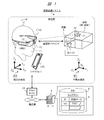
- the information terminal 1 holds the spatial data 6 of the target space 2 to be used, and the information terminal 1 obtains the spatial data 6 from an external source. You may get it. In the latter case, as in the example shown in FIG. 1, the information terminal 1 acquires the spatial data 6 from, for example, the server 4.
- the space data 6 is data in which the shape of the space 2 and the like are described. Space 2 is, for example, a room or area in a building.
- the identification information (ID) associated with the space 2 and the space data 6 is posted / displayed in advance in the form of a sign 3 or the like.
- Spatial data 6 representing the ID and shape of each space 2 is registered in advance in the DB 5 of the information terminal 1 or the server 4 as a library. The details of the configuration and method of the spatial data 6 are not limited.
- the information terminal 1 is a device such as an HMD 1A or a smartphone 1B having a function of displaying a virtual image 22 according to a real position 21 in the space 2 of the outside world.
- the information terminal 1 has a terminal coordinate system WA as the world coordinate system of its own machine.
- Space 2 has a space coordinate system W1 as a world coordinate system. These coordinate systems are different.
- the sign 3 and the space 2 have a predetermined positional relationship, and the position, shape, and the like are described in the space data 6 in the same space coordinate system W1.
- This spatial recognition system and method has a mechanism for efficiently matching the terminal coordinate system WA and the spatial coordinate system W1.
- the information terminal 1 recognizes an ID from a sign 3 provided in association with the space 2 to be used, and identifies the spatial data 6 based on the ID. After specifying the spatial data 6, the information terminal 1 uses the spatial data 6 stored in the information terminal 1 or acquires the spatial data 6 from the server 4 by communication.
- the information terminal 1 uses the space data 6 to perform an operation of matching the terminal coordinate system WA of its own machine with the space coordinate system W1 of the target space 2 as a coordinate system pairing described later.
- the information terminal 1 shares position recognition with the space 2 by performing coordinate system pairing so that the position and orientation in the terminal coordinate system WA match the space coordinate system W1.
- the information terminal 1 can display a virtual image 22 such as AR at a desired position 21 with high accuracy while appropriately converting positions and directions between those coordinate systems.
- the information terminal 1 identifies the spatial data 6 from the sign 3 and measures and calculates the relationship between the position and orientation of the information terminal 1 with respect to the sign 3 for coordinate system pairing. As a result, the information terminal 1 performs initial settings regarding the position and orientation of the information terminal 1 in the terminal coordinate system WA with respect to the spatial coordinate system W1 that describes the spatial data 6.
- the information terminal 1 can perform matching between the coordinate systems as an initial setting almost at the same time as specifying the spatial data 6 from the sign 3.
- the information terminal 1 of the user U1 can quickly realize the coordinate system matching and the position recognition sharing with respect to the space 2 at the place of the sign 3 such as the entrance of the room, which is convenient for the user. The effect such as improvement can be obtained.
- the space can be recognized more quickly and errors and errors can be reduced as compared with the case where the shape of the space is measured after the information terminal enters the room.
- FIG. 1 shows the configuration of the spatial recognition system of the first embodiment.
- the space recognition system of the first embodiment is a server in which spatial data 6 is registered when the information terminal 1 carried or worn by the user U1, the space 2 to be used by the information terminal 1, and the server 4 are used. Has 4 and.
- the information terminal 1 is connected to a communication network including the Internet, a mobile network, and the like through a wireless LAN access point 23 and the like.
- the information terminal 1 communicates with an external device such as a server 4 via a communication network.
- the HMD1A which is the information terminal 1, is provided with a transmissive display surface 11, a camera 12, a distance measuring sensor 13, and the like in a housing.
- the HMD1A has a function of displaying a virtual image of AR on the display surface 11.
- the smartphone 1B includes a display surface such as a touch panel, a camera, a distance measuring sensor, and the like, and has a function of displaying a virtual image of AR on the display surface.
- Space 2 is an arbitrary space that is associated with ID and spatial data 6 and managed by identification or division, for example, one room.
- the sign 3 is installed on the outer surface of the wall near the entrance of this room.
- the sign 3 (in other words, a marker, a sign, etc.) has a special function for the information terminal 1 in addition to a function as a general sign that enables the user U1 to identify the space 2.
- the special function of the sign 3 enables the information terminal 1 to identify the space 2 (corresponding ID) and identify the space data 6, and further realizes an operation of adapting the coordinate system according to the space 2. It is a function for.
- the server 4 is a server device managed by a business operator or the like, and is provided on, for example, a data center or a cloud computing system.
- the server 4 registers and holds the ID and the spatial data 6 as a library in the internal or external database (DB) 5.
- Spatial data 6 is similarly registered for each of the plurality of spaces 2 and the sign 3.
- the server 4 may manage the spatial data 6 closed in a unit such as a company, or may manage a large number of spatial data 6 in a unit such as the earth or a region. For example, when the spatial data 6 is managed in units of a company building, each spatial data 6 relating to each space 2 in the building is registered in the server 4 of a computer system such as a corporate LAN.
- the smartphone 1B is used as the information terminal 1, the same functions as those of the HMD 1A can be realized.
- the user U1 sees a virtual image 22 such as AR displayed on the display surface of the smartphone 1B held in his / her hand.
- the coordinate system that serves as a reference for designating the position in the real space in the information terminal 1 and the space 2 (corresponding space data 6) is called a world coordinate system.
- the information terminal 1 of FIG. 1 has a terminal coordinate system WA as a world coordinate system representing the position and orientation of the own machine.
- the terminal coordinate system WA is a coordinate system for recognizing and controlling the position, orientation (in other words, posture, rotation state), image display position, and the like of the information terminal 1.
- Space 2 has a space coordinate system W1 as a world coordinate system representing the position and orientation of the space 2.
- the spatial data 6 is described in the spatial coordinate system W1.
- the terminal coordinate system WA and the spatial coordinate system W1 are basically different coordinate systems. The origin and direction of each world coordinate system are fixed in real space (earth, region, etc.). These coordinate systems do not match in the first place.
- Terminal coordinate system WA has the origin O A, the axis X A as 3 orthogonal axes, the axis Y A, and a shaft Z A.
- Space coordinate system W1 has, as an origin O 1, the axis X 1 as 3 orthogonal axes, the axis Y 1, and a shaft Z 1.
- the origin O A and the origin O 1 are fixed at predetermined positions in the real space, respectively.
- the position LA of the information terminal 1 in the terminal coordinate system WA is, for example, a predetermined housing center position (FIG. 8).
- the position L1 of the sign 3 in the spatial coordinate system W1 is, for example, a predetermined position corresponding to one feature point in the sign 3 (FIG. 8).
- the space coordinate system W1 may be a local coordinate system unique to a building or the like including the space 2, or may be a coordinate system commonly used in the earth or a region consisting of latitude, longitude, and altitude.
- the spatial coordinate system W1 is a unique local coordinate system commonly used in a plurality of rooms in a certain building.
- the information terminal 1 performs coordinate system pairing of its own terminal coordinate system WA with respect to the spatial coordinate system W1 of the target space 2. As a result, the information terminal 1 can control the display of the virtual image 22 according to the position and shape in the spatial coordinate system W1. After pairing the coordinate system, the information terminal 1 is not limited to performing internal control of its own machine based on the terminal coordinate system WA while being used in the space 2, but is basically based on the space coordinate system W1. It is also possible to do as.
- FIG. 2 shows an outline of the space recognition method of the first embodiment. This method has steps S1 to S5 shown.
- step S1 the information terminal 1 HMD1A photographs the sign 3 with the camera 12 at the location of the sign 3 posted in association with the space 2 to be used, based on the operation of the user U1. And confirm and acquire the ID of the space 2 from the sign 3. As a result, the information terminal 1 starts the coordinate system pairing with respect to the target space 2.
- the spatial data 6 is, in detail, data including spatial shape data 6A, marker data 6B, and measurement target position information 6C. Alternatively, it may be a data group in which another marker data 6B or the like is associated with the spatial data 6. If the information terminal 1 already holds the spatial data 6, the acquisition of the spatial data 6 from the server 4 can be omitted.
- the space shape data 6A is data in which the positions and shapes of the arrangements (including walls and the like) constituting the space 2 are described in the space coordinate system W1.
- the label data 6B is data in which the position, shape, and the like of the label 3 are described in the spatial coordinate system W1, and includes various quantity data 202.
- the quantity data 202 is measured and described in advance.
- the quantities are defined parameters required for coordinate system pairing (specifically, calculation of conversion parameter 7) (FIG. 8 described later).
- the measurement target position information 6C is data in which a measurement target position (for example, a feature point or a feature line) or the like, which is a reference when the information terminal 1 measures the relationship with the sign 3, is defined.
- the format of these data / information is an example.
- the spatial shape data 6A may be merged with the marker data 6B, or the marker data 6B may be merged with the measurement target position information 6C.
- the measurement target position information 6C can be omitted when it is set or implemented in the program or the like of the information terminal 1 in advance.
- step S3 the information terminal 1 measures the relationship between the position and the orientation with the sign 3 based on the measurement target position information 6C, and obtains it as various quantity data 201 on the terminal side (FIG. 8).
- This relationship is an expression such as the position and orientation of the sign 3 as seen in the terminal coordinate system WA, and is particularly an expression relating to two different specific directions in the real space.
- the process of step S3 can be performed almost simultaneously with the process of steps S1 and S2, for example, in parallel.
- step S4 the information terminal 1 uses the quantity data 202 on the space 2 side acquired in step S2 and the quantity data 201 on the terminal side measured in step S3, and uses the terminal coordinate system WA and the space coordinate system W1. Generate conversion parameter 7 for coordinate system pairing with and set it in your own machine. As a result, the information terminal 1 ends the coordinate system pairing with respect to the space 2.
- the information terminal 1 may measure and hold a part of the various quantity data 201 on the terminal side in advance, or may measure it as needed.
- step S5 the information terminal 1 of the user U1 appropriately uses the conversion parameter 7 to convert the position and orientation between the terminal coordinate system WA and the space coordinate system W1 while converting the position and orientation in the space 2.
- the virtual image 22 can be displayed at a desired position 21.
- the information terminal 1 may maintain the state of the coordinate system pairing with respect to the space 2, or may explicitly cancel it.
- the conversion parameter 7 is held in the information terminal 1.
- canceling the information terminal 1 deletes the conversion parameter 7, for example, and then generates the conversion parameter 7 again when the coordinate system pairing with the same space 2 is performed again.
- the information terminal 1 may automatically delete the conversion parameter 7 after a certain period of time has elapsed after the coordinate pairing.
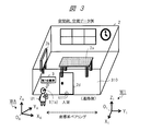
- FIG. 3 shows a configuration example of the space 2 and an example of the positional relationship between the space 2 and the sign 3.
- This space 2 is, for example, one room in a building such as a company, for example, a seventh conference room.
- the user U1 confirms the sign 3 before entering the room which is the target space 2 in which the information terminal 1 is used.
- the user U1 sees the sign 3 at that location through the information terminal 1 HMD1a.
- the coordinate system pairing of the terminal coordinate system WA with respect to the system W1 is performed.
- the terminal coordinate system WA of the information terminal 1 conforms to the space coordinate system W1 of the space 2.
- those coordinate systems are generally regarded as one coordinate system as a whole, and the position recognition can be shared.
- User U1 enters the room and uses HMD1a in the room. Using the space data 6, the HMD1a can quickly and accurately display the virtual image 22 of the AR at the position 21 that matches the shape of the space 2.
- Spatial data 6, especially spatial shape data 6A is, for example, data in an arbitrary format representing the position and shape of the room.
- the spatial data 6 includes data representing the boundary of the space 2 and data of an arbitrary object arranged in the space 2.
- the data representing the boundary of the space 2 includes, for example, data of an arrangement such as a floor, a wall, a ceiling, and a door 2d constituting the room. There may be no placement at the boundary.
- the data of the object in the space 2 includes, for example, the data of the desk 2a and the whiteboard 2b arranged in the room.
- the sign 3 may be provided on the door 2d or the like.
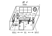
- FIG. 4 as an example of use in the space 2 of FIG. 3, two users U1 and U2 share a spatial coordinate system W1 corresponding to the space 2 of the room, and each information terminal 1 shares an AR.
- An example of displaying the same virtual image 22 at the same position 21 is shown.
- the user U1 pairs the terminal coordinate system WAU1 of his / her HMD1a with respect to the spatial coordinate system W1 through the marker 3.
- the user U2 pairs the terminal coordinate system WAU2 of his / her HMD1b with the same spatial coordinate system W1 through the marker 3.
- the HMD1a of the user U1 and the HMD1b of the user U2 are in a state where the position recognition is shared through the same spatial coordinate system W1.
- the HMD1a of the user U1 and the HMD1b of the user U2 display the same virtual image 22 in accordance with the desired same positions in the space 2, for example, the center position 21 on the upper surface of the desk 2a designated by one user. can do.
- User U1 and user U2 can work and communicate while viewing the same virtual image 22.
- the spatial shape data 6A also includes data on the shape of the desk 2a, for example. Its shape has a position and orientation in the spatial coordinate system W1.
- the HMD1a displays the virtual image 22 on the display surface 11 of the own machine so as to align with the position 21 designated by the user U1.
- the HMD1a uses the conversion parameter 7 to convert the position 21 in the spatial coordinate system W1 to the position in the terminal coordinate system WAU1.
- the HMD1a may transmit the position 21 for displaying the virtual image 22 and the data of the virtual image 22 to be displayed to the HMD1b by wireless communication.
- the HMD1b displays the virtual image 22 at the position 21 transmitted from the HMD1a.
- the information terminal 1 has a function (corresponding application program or the like) such as AR that can handle the spatial data 6 including the spatial shape data 6A of FIG.
- the space shape data 6A is, for example, polygon data having a set of surface data of a plurality of surfaces constituting the space 2.
- the spatial shape data 6A includes data on floors, walls, ceilings, etc., and data on desks 2a, whiteboards 2b, other equipment, and the like.
- the boundary of the space 2 is not necessarily limited to the actual object such as a wall, and may be a boundary invisible to the user.
- the object arranged in the space 2 may be an object invisible to the user, for example, equipment or piping in the wall.
- the data group including the marker data 6B and the like is collectively referred to as the spatial data 6 for easy understanding in the explanation, but the configuration is not limited to such a configuration.
- the sign data 6B is data that defines the sign 3, and includes data representing the position, orientation, shape, etc. of the sign 3 with respect to the spatial coordinate system W1 of the space 2, particularly various quantity data 202 (FIG. 2).
- the sign 3 is also regarded as a part constituting the space 2
- the sign 3 is defined as one object in the space shape data 6A, and the sign data 6B may be omitted.
- the measurement target position information 6C is data that defines how to measure when measuring the position and orientation relationship between the information terminal 1 and the sign 3.
- the measurement target position information 6C is information for designating three feature points or two feature lines to be measured. Further, in this system and method, when the measurement target position information is uniformly defined regardless of each space 2, the measurement target position information 6C is implemented in the control program or the like of the information terminal 1. May be good. In the first embodiment, the measurement target position information 6C can be set for each of the space 2 and the sign 3.
- FIG. 5 shows a configuration example of the label 3.
- (A) is a first example
- (B) is a second example
- (C) is a third example
- (D) is a fourth example.
- the sign 3 in (A) the character string "7th meeting room" indicating the name of the room is written on a surface (sometimes referred to as a sign surface) such as a horizontally long rectangular plate.
- the label surface is arranged in Y 1 -Z 1 side of the spatial coordinate system W1.
- the ID 301 of the space 2 is directly described as a character string in one place on the sign surface.
- the information terminal 1 can recognize the ID 301 by the camera 12.
- the configuration such as the shape of the sign 3 is described in the sign data 6B.
- This marking surface has four corner points, and as three corner points, points p1, p2, and p3 are defined in advance as feature points that are specific objects to be measured.
- the point p1 is defined as the upper left corner point of the sign surface
- the point p2 is defined as the lower left corner point of the sign surface
- the point p3 is defined as the upper right corner point of the sign surface.
- the measurement target position information 6C includes designation of the three feature points or two corresponding feature lines. In other words, the measurement target position information 6C includes an instruction that two feature lines (two corresponding specific directions) of the left side and the upper side of the sign 3 should be measured.
- the point p1 is defined as a feature point representing a typical position of the marker 3.
- feature points such as point p1 and feature lines such as vector v1 are shown, but they are not actually described.
- the feature points and feature points may be intentionally described as specific images on the sign surface so that they can be recognized by the user and the information terminal 1.
- the information terminal 1 measures these three feature points (points p1 to p3) based on the measurement target position information 6C.
- the information terminal 1 measures the relationship with these three points by analyzing the images of the distance measuring sensor 13 and the camera 12.
- the terminal coordinate system WA it is the same as that the two feature lines corresponding to the two vectors v1 and v2 shown in the figure can be grasped.
- the vector v1 is a vector from the point p1 to the point p2 corresponding to the left side of the marking surface
- the vector v2 is a vector from the point p1 to the point p3 corresponding to the upper side of the marking surface.
- the ID of the space 2 is described in the mode of the code image 302 which is a coded image in one place on the sign surface similar to that in (A).
- a two-dimensional code such as a QR code (QR: Quick Response, registered trademark) may be used.
- QR code Quick Response, registered trademark
- these ID 301 and the code image 302 may be a URL for accessing the spatial data 6 of the server 4 or an image encoded by the URL.
- the information terminal 1 extracts the code image 302 from the captured image of the camera 12 and obtains information such as an ID by decoding.
- the sign 3 in (C) does not describe the character string of the name of the space 2 on the sign surface, and only the rectangular code image 302 is displayed.
- the information terminal 1 may measure the three corner points of the code image 302 in the same manner with respect to the relationship with the sign 3.
- the three corner points may be used as three cutout symbols for recognizing the QR code.
- the configuration of the feature points or feature lines (two specific directions) for measuring the relationship with the sign 3, which is the various quantity data 201 on the terminal side, is not limited to the above example, and can be measured in any case. It can be specified by the target position information 6C.
- the target position information 6C For example, in the marking plane, three feature points or two feature lines may be described as a specific image.
- a feature point or a feature line to be a measurement target may be defined at a place separated from the object of the sign 3 by a predetermined positional relationship.
- the spatial side quantity data 202 (FIG. 2) includes coordinate values that represent positions in the spatial coordinate system W1 for at least one feature point (eg, point p1) of the marker 3. Further, the various quantity data 202 includes coordinate values in the spatial coordinate system W1 for two different feature points (for example, points p2 and p3), or as feature line data, feature lines in two different directions (for example, feature lines in two different directions). For example, the representation of the vectors v1 and v2) in the spatial coordinate system W1 is included. One feature line (eg, vector v1) and two feature points (eg, points p1, p2) can be replaced.
- the position information of the space 2 or the sign 3 may be included as the ID of the space data 6 that can be read from the sign 3.
- the location information may be general ones such as latitude, longitude, and height, or may be a local representation form in the building. This position information is convenient for classifying and searching the spatial data 6, and can also be used when inquiring the server 4 about the position of the sign 3 existing near the current position of the own machine.
- the server 4 may reply with an image of the sign 3 about the information about the sign 3 near the position of the terminal that received the inquiry.
- FIG. 6 shows an example of the appearance configuration of the HMD1A as an example of the information terminal 1.
- the HMD1A includes a display device including a display surface 11 in a spectacle-shaped housing 10.
- This display device is, for example, a transmissive display device, and a real image of the outside world is transmitted through the display surface 11, and the image is superimposed and displayed on the real image.
- a controller, a camera 12, a distance measuring sensor 13, another sensor unit 14, and the like are mounted on the housing 10.
- the camera 12 has, for example, two cameras arranged on the left and right sides of the housing 10, and captures a range including the front of the HMD to acquire an image.
- the distance measuring sensor 13 is a sensor that measures the distance between the HMD1A and an object in the outside world. As the distance measuring sensor 13, a TOF (Time Of Flight) type sensor may be used, or a stereo camera or another type may be used.
- the sensor unit 14 includes a group of sensors for detecting the position and orientation of the HMD1A.
- an audio input device 18 including a microphone, an audio output device 19 including a speaker and an earphone terminal, and the like are provided.
- the information terminal 1 may be equipped with an operator such as a remote controller.
- the HMD1A performs, for example, short-range wireless communication with the actuator.
- the user can input instructions related to the functions of the HMD1A, move the cursor on the display surface 11, and the like.
- the HMD1A may communicate with an external smartphone, PC, or the like to cooperate with each other.
- the HMD1A may receive image data for AR from the application of the smartphone 1B.
- the information terminal 1 includes an application program or the like for displaying a virtual image such as AR on the display surface 11 for work support or entertainment. For example, the information terminal 1 generates a virtual image 22 for work support by processing an application for work support, and virtually at a predetermined position 21 near a work object in space 2 on the display surface 11. Image 22 is arranged and displayed.
- FIG. 7 shows an example of the functional block configuration of HMD1A of FIG.
- the information terminal 1 includes a processor 101, a memory 102, a camera 12, a distance measuring sensor 13, a sensor unit 14, a display device 103 including a display surface 11, a communication device 104, a voice input device 18 including a microphone, and a voice output including a speaker. It includes a device 19, an operation input unit 105, a battery 106, and the like. These elements are connected to each other through a bus or the like.
- the processor 101 is composed of a CPU, ROM, RAM, etc., and constitutes an HMD1A controller.
- the processor 101 realizes functions such as an OS, middleware, and applications, and other functions by executing processing according to the control program 31 and the application program 32 of the memory 102.
- the memory 102 is composed of a non-volatile storage device or the like, and stores various data and information handled by the processor 101 and the like.
- the memory 102 also stores images, detection information, and the like acquired by the camera 12 and the like as temporary information.
- the camera 12 acquires an image by converting the light incident from the lens into an electric signal by the image sensor.
- the distance measuring sensor 13 calculates the distance to an object from the time until the light emitted to the outside world hits the object and returns.
- the sensor unit 14 includes, for example, an acceleration sensor 141, a gyro sensor (angular velocity sensor) 142, a geomagnetic sensor 143, and a GPS receiver 144.
- the sensor unit 14 detects a state such as the position, orientation, and movement of the HMD1A by using the detection information of these sensors.
- the HMD1A is not limited to this, and may include an illuminance sensor, a proximity sensor, a barometric pressure sensor, and the like.
- the display device 103 includes a display drive circuit and a display surface 11, and displays a virtual image 22 or the like on the display surface 11 based on the image data of the display information 34.
- the display device 103 is not limited to the transparent display device, and may be a non-transparent display device or the like.
- the communication device 104 includes a communication processing circuit, an antenna, and the like corresponding to various predetermined communication interfaces. Examples of communication interfaces include mobile networks, Wi-Fi (registered trademark), Bluetooth (registered trademark), infrared rays and the like.
- the communication device 104 performs wireless communication processing and the like with another information terminal 1 and the access point 23 (FIG. 1).
- the communication device 104 also performs short-range communication processing with the actuator.
- the voice input device 18 converts the input voice from the microphone into voice data.
- the voice output device 19 outputs voice from a speaker or the like based on the voice data.
- the voice input device may include a voice recognition function.
- the voice output device may include a voice synthesis function.
- the operation input unit 105 is a part that receives operation inputs to the HMD1A, such as power on / off and volume adjustment, and is composed of a hardware button, a touch sensor, and the like.
- the battery 106 supplies electric power to each part.
- the controller by the processor 101 has a communication control unit 101A, a display control unit 101B, a data processing unit 101C, and a data acquisition unit 101D as a configuration example of a functional block realized by processing.
- the memory 102 stores the control program 31, the application program 32, the setting information 33, the display information 34, the coordinate system information 35, the spatial data information 36, and the like.
- the control program 31 is a program for realizing control including a spatial recognition function.
- the application program 32 is a program that realizes a function such as AR that uses the spatial data 6.
- the setting information 33 includes system setting information and user setting information related to each function.
- the display information 34 includes image data and position coordinate information for displaying an image such as a virtual image 22 on the display surface 11.
- the coordinate system information 35 is management information related to the space recognition function.
- the coordinate system information 35 is converted from the information of the terminal coordinate system W1 of the own machine, the information of the space coordinate system W1 of the target space 2, the various amount data 201 on the terminal side, and the various amount data 202 on the space 2 side. Includes parameter 7 and.
- the information of the space coordinate system W1 and the quantity data 202 on the space 2 side are obtained from the space data 6.
- the spatial data information 36 is information on the spatial data 6 held as a library in the information terminal 1 and the spatial data 6 acquired from the server 4.
- the information terminal 1 also records the measured data by using an appropriate feature in the outside world as a marker 3. Further, the information terminal 1 records information that can identify the space 2, such as a sign of a conference room, as a space ID.
- the communication control unit 101A controls the communication process using the communication device 104 when acquiring the spatial data 6 from the server 4.
- the display control unit 101B uses the display information 34 to control the display of the virtual image 22 and the like on the display surface 11 of the display device 103.
- the data processing unit 101C reads and writes the coordinate system information 35, performs processing for managing the terminal coordinate system WA, processing of coordinate system pairing with the spatial coordinate system W1, and inter-coordinate systems using the conversion parameter 7. Perform conversion processing, etc.
- the data processing unit 101C At the time of coordinate system pairing, the data processing unit 101C generates a process of acquiring the quantity data 202 on the space 2 side from the space data 6, a process of measuring the quantity data 201 on the terminal side, and a conversion parameter 7. Perform processing, etc.
- the data acquisition unit 101D acquires each detection data from various sensors such as the camera 12, the distance measuring sensor 13, and the sensor unit 14. At the time of coordinate system pairing, the data acquisition unit 101D measures the various quantity data 201 on the terminal side according to the control from the data processing unit 101C.
- FIG. 8 shows the coordinate system and various features when the HMD1A, which is the information terminal 1 of the user U1, performs coordinate system pairing using the spatial data 6 of the target space 2 in the real space corresponding to FIG.
- An explanatory diagram regarding the amount is shown.
- the information terminal 1 performs an operation of adapting the terminal coordinate system WA of its own unit to the space coordinate system W1 of the target space 2 as a coordinate system pairing, in other words, an operation of associating the terminal coordinate system WA with the space coordinate system W1. I do.
- coordinate system pairing is performed between the terminal coordinate system WA of a certain HMD1A and the spatial coordinate system W1 of a certain space 2 will be described.
- the information terminal 1 acquires the space data 6 specified based on the ID recognized from the sign 3 in the space 2 from the server 4 (step S2 in FIG. 2), or the space in its own machine. If the information corresponding to the data 6 is possessed, that information is used.
- the spatial data 6 includes the spatial shape data 6A, the marker data 6B, and the measurement target position information 6C of FIG.
- the label data 6B includes quantities 802 ⁇ N 1 , M 1 , d 1 ⁇ for the label 3. This quantity 802 corresponds to the quantity data 202 on the space side of FIG.
- the measurement target position information 6C is information that defines the measurement of various quantities 801.
- the information terminal 1 is given quantities 801 with respect to its own device ⁇ N A, M A, d A, P 1A ⁇ to measure. This quantity 801 corresponds to the quantity data 201 on the terminal side of FIG.
- the information terminal 1 calculates the relationship between the terminal coordinate system WA and the space coordinate system W1 based on the various quantities 801 on the terminal side and the various quantities 802 on the sign 3 side (corresponding space 2 side).
- the information terminal 1 calculates a conversion parameter 7 for conversion regarding the position and orientation between the two coordinate systems of the terminal coordinate system WA and the spatial coordinate system W1.
- the information terminal 1 sets and holds the conversion parameter 7 generated by the calculation in its own machine.
- the information terminal 1 can convert the position and the like between the two coordinate systems by appropriately using the conversion parameter 7 in the space 2 represented by the space data 6.
- the above operation is described as coordinate system pairing.
- the following element information is provided as various quantities at the time of coordinate system pairing.
- the quantities have a specific direction vector as the first information, a world coordinate value as the second information, and a marker position vector as the third information.
- the coordinates 802 on the sign 3 side corresponding to the space 2 are (1) first specific direction vector N 1 and (2) second specific. It has three pieces of information: the direction vector M 1 and (3) the coordinate value d 1 with respect to the position L1 of the marker 3.
- Quantities 801 of the information terminal 1 quantities data 201 in FIG.
- n and m be the unit vectors for two different specific directions in the real space. These unit vectors n, a representation of the spatial coordinate system W1 for m, and n 1, m 1, a representation of the information terminal 1 of the terminal coordinate system WA for these unit vectors, and n A, m A To do.
- the two specific directions on the side of the marker 3 correspond to the two feature lines (vectors v1 and v2) of the indicator 3 of FIG. 5, the first specific direction vector N 1 and the second specific direction vector M. It is 1.
- the representations n 1 , m 1 of the specific directions (N 1 , M 1 ) in the spatial coordinate system W1 regarding the marker 3 are described in advance in the marker data 6B in the spatial data 6.
- a first specific direction vector N A a second specific direction vector M A.
- the information terminal 1 a specific direction (N A, M A) of the terminal coordinate system WA measuring the expression n A, m A of.
- a vertically downward direction gravitation direction
- the gravitational direction can be measured as the gravitational acceleration direction by the three-axis acceleration sensor which is the acceleration sensor 141 (FIG. 7) of the information terminal 1.
- the vertically downward direction, Z axis shown (Z A, Z 1) may be set as a negative direction.
- the vertical downward direction which is a specific direction, does not change in the world coordinate system, it is not necessary to measure each time the coordinate system pairing is performed.
- the geomagnetic direction for example, the north direction is used as one specific direction
- the geomagnetic direction can be measured by the geomagnetic sensor 143 (FIG. 7). Since the geomagnetism may be affected by the structure, it is preferable to measure it for each coordinate system pairing. If the effect of the structure is known to be small enough, it is not necessary to measure each coordinate system pairing.
- the representation of the directions of the two feature lines (corresponding vectors v1 and v2) in the marker 3 as seen in the terminal coordinate system WA may be used.
- the information terminal 1 measures the specific direction corresponding to the feature line (for example, vector v1) of the sign 3 in the terminal coordinate system WA, and obtains the expression in the terminal coordinate system WA for the specific direction. This measurement is possible, for example, by the distance measuring sensor 13.
- the information terminal 1 measures, for example, each coordinate value in the terminal coordinate system WA for two feature points (points p1 and p2) constituting the feature line corresponding to the vector v1.
- the information terminal 1 obtains the expression of the specific direction vector (N 1 ) in the terminal coordinate system WA from the coordinate values of those two points. Representation of this specific direction vector (N 1) is different from the representation of the first specific direction vector N A of quantities 802 of label 3 side.
- d 1 (x 1 , y 1 , z 1 ) be the coordinate values in the spatial coordinate system W1 for one feature point (for example, point p1) representing the position L1 on the sign 3 side.
- the coordinate value d 1 is described in advance in the marker data 6B.
- the typical position L1 of the marker 3 is represented by the point p1, but the present invention is not limited to this.
- d A (x A , y A , z A ) be the coordinate value in the terminal coordinate system WA for the position LA on the information terminal 1 side.
- the typical position LA of the information terminal 1 is represented by the center position of the housing 10, but the present invention is not limited to this.
- the terminal position vector V A represents the vector from the origin O A terminal coordinate system WA to the position LA.
- the feature point position vector V 1 indicates a vector from the origin O 1 to the position L1 in the spatial coordinate system W1.
- the origin O A position LA position and the information terminal 1 of the terminal coordinate system WA different from the position L1 of the position and the marker 3 the origin O 1 space coordinate system W1.
- the origin of the world coordinate system does not match the position of the information terminal 1 or the position of the sign 3.
- the origin of the terminal coordinate system WA and the position of the information terminal 1 may be the same, or the origin of the spatial coordinate system W1 and the position of the sign 3 may be the same. It is applicable as well.
- An example of the former, the information terminal 1 and the like may be set its own position when starting at the origin O A terminal coordinate system WA. Examples of the latter include the case where a predetermined position in the space 2, such as a room is set as the origin O 1 of the spatial coordinate system W1 in advance spatial data 6.
- the label position vector P 1A is a vector from the position LA (coordinate value d A ) of the information terminal 1 to the position L1 (coordinate value d 1 ) of the feature point of the marker 3.
- the marker position vector P 1A is a representation of the position L1 of the indicator 3 in the terminal coordinate system WA.
- the information terminal 1 can measure the marker position vector P 1A by, for example, the distance measuring sensor 13. From this marker position vector P 1A , information regarding the relationship between the two coordinate systems of the terminal coordinate system WA and the spatial coordinate system W1 can be obtained.
- [Conversion parameter] By acquiring and measuring various quantities at the time of the above coordinate system pairing, the information terminal 1 can understand the relationship between the terminal coordinate system WA and the spatial coordinate system W1 from the relationship with the marker 3, and the conversion between the two coordinate systems.
- Parameter 7 can be calculated.
- the conversion represented by the conversion parameter 7 is a conversion for matching the spatial coordinate system W1 with the terminal coordinate system WA, or conversely, a conversion for matching the terminal coordinate system WA with the spatial coordinate system WA.
- the table of the conversion parameter 7 includes, as a configuration example, the identification information of the spatial coordinate system W1, the identification information of the terminal coordinate system WA, and the information of the representation of the rotation between those two coordinate systems (q A1 described later). , Has information on the representation of the origin between those two coordinate systems (origin-to-origin vector o 1A ).
- the information terminal 1 After the establishment of the coordinate system pairing, the information terminal 1 does not need to measure the position, shape, etc. of the spatial data 6 in the arrangement constituting the space 2 represented by the spatial shape data 6A without the need for measurement processing by the own machine. Can be grasped quickly. Then, based on the grasp, the information terminal 1 can display the virtual image 22 on the display surface 11 with high accuracy so as to be aligned with the desired position 21 in the space 2 as illustrated in FIG.
- the desired position 21 can be specified by the user U1 by operation, or can be automatically determined according to the application program or the like of the information terminal 1.
- the position vector G A a vector for the display of the position 21 of the virtual image 22 in the terminal coordinate system WA
- position coordinates r A is the coordinate value of the position 21.
- the position vector G 1 is a vector for the position 21 in the spatial coordinate system W1
- the position coordinate value r 1 is a coordinate value of the position 21.
- the inter-origin vector o 1A is a vector from the origin O A to the origin O 1 , and is a representation of the origin O 1 in the terminal coordinate system WA.
- Origin between the vectors o A1 is a vector from the origin O 1 to the origin O A, is a representation of the origin O A in the spatial coordinate system W1.
- the representation of the position of the spatial data 6 in the spatial coordinate system W1 may be converted into the representation in the terminal coordinate system WA by the conversion parameter 7. Good.
- the expression of the position in the terminal coordinate system WA is expressed by the conversion parameter 7 (which defines the reverse conversion to the above). It may be converted into the representation of the position in the coordinate system W1.
- the information terminal 1 may use at least one of the above two types of conversions (corresponding conversion parameter 7), and may use both conversions.
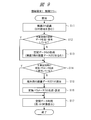
- FIG. 9 shows a control flow of the information terminal 1.
- the flow of FIG. 9 has steps S11-S17.
- step S11 the information terminal 1 recognizes the sign 3 by using the camera 12, the distance measuring sensor 13, and the like, and acquires the ID of the space 2 from the sign 3.
- the information terminal 1 starts the procedure for establishing the coordinate system pairing based on the recognition of the sign 3.
- step S12 the information terminal 1 confirms whether or not the spatial data 6 specified by its ID is already possessed in the information terminal 1 (spatial data information 36 of the memory 102 in FIG. 7 and the like). If it is possessed (Y), the process proceeds to step S14, and if it is not possessed (N), the process proceeds to step S13.
- step S13 the information terminal 1 acquires the spatial data 6 from the DB 5 of the server 4 by communication using the communication device 104 (FIG. 7) using the ID.
- the spatial data 6 includes the quantity data 202 on the label 3 side (quantity 802 in FIG. 8).
- step S14 the information terminal 1 confirms whether or not the conversion parameter 7 between the coordinate systems relating to the target space 2 is already possessed in the information terminal 1 (coordinate system information 35 of the memory 102 in FIG. 7 and the like). If it is possessed (Y), steps S15 and S16 are skipped and the process proceeds to step S17.
- step S15 the information terminal 1 measures the quantity data 201 (quantity 801 in FIG. 8) on the terminal side using the camera 12, the distance measuring sensor 13, and the like.
- step S16 the information terminal 1 uses the quantity data 202 on the marker 3 side obtained in step S13 and the quantity data 201 on the terminal side obtained in step S15, and uses the terminal coordinate system WA and the spatial coordinate system W1. Generate conversion parameter 7 between and, and set it in your own machine. This completes the procedure for establishing coordinate system pairing.
- step S17 the information terminal 1 uses the spatial data 6 (corresponding spatial data information 36) obtained in step S13 by any method or application.
- the information terminal 1 displays the virtual image 22 of the AR at a desired position 21 as shown in FIG. 4 so as to match the position and shape of the arrangement in the space 2 represented by the space shape data 6A.
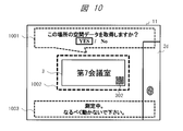
- FIG. 10 shows an AR display example on the display surface 11 of the information terminal 1 at the time of coordinate system pairing.
- the information terminal 1 may display a screen for transmitting an operation or a state to the user U1 and output a voice accompanying the screen display.
- This example shows an example in which an image for a guide is displayed on the display surface 11 when the information terminal 1 measures various quantities 801 in step S15 of FIG.
- This example shows a state when the user U1 sees the sign 3 as shown in FIG. 5 (B) in front of the room as shown in FIG.
- the sign 3 is visible on the display surface 11.
- the information terminal 1 recognizes the sign 3 based on the image of the camera 12 in step S11 of FIG. At this time, the information terminal 1 superimposes and displays, for example, the image 1001 and the image 1002 on the real image.
- the image 1002 is an image like a frame surrounding the recognized sign 3, and is information that clearly conveys to the user U1 that it is a specific sign 3.
- the image 1002 may be an image surrounding the code image 302 portion, or may be an image emphasizing the above-mentioned feature lines and the like.
- the image 1001 is a message such as "Do you want to acquire the spatial data of this place? YES / NO" displayed in response to the recognition of the sign 3, and is information for confirming whether to acquire the spatial data 6 to the user U1. Is. YES / NO can be selected from the image 1001 by the operation of the user U1. When YES is selected, the information terminal 1 executes the processes after step S11.
- Image 1003 is a message such as "Measuring. Please do not move as much as possible.” Displayed at the start of measurement and during measurement in step S15.
- the information terminal 1 may output such guide information to the user U1 for more accurate measurement.
- Equation 1 The normalized quaternion q representing the rotation of the angle ⁇ with the unit vector (n X , n Y , n Z ) as the rotation axis is given by the following equation 1.
- i, j, and k are units of quaternions.
- the symbols representing coordinate points and vectors that are not component display are quaternion display. Further, it is assumed that the symbol representing rotation is a normalized quaternion.
- FIG. 11 shows an explanatory diagram of the transformation of the coordinate system.
- FIG. 11A similarly to FIG. 8, the representation regarding the same position 21 in the real space and the coordinate origin (OA, A) between two different coordinate systems of the terminal coordinate system WA and the spatial coordinate system W1 are shown.
- the expression of the difference of O 1) is shown.
- As an expression of the position 21 has a position vector G A, the position coordinates r A, the position vector G 1 and the position coordinates r 1.
- the inter-origin vectors o 1A and o A1 are provided.
- the inter-origin vector o 1A is a representation of the origin O 1 of the spatial coordinate system W1 in the terminal coordinate system WA.
- Origin between the vectors o A1 is an expression of the origin O A terminal coordinate system WA in the spatial coordinate system W1.
- the relationship of the coordinate system (WA, W1) can be calculated as follows. In the following, the calculation for obtaining the difference between the rotation and the coordinate origin when the representation of the coordinate value and the vector value in the spatial coordinate system W1 describing the spatial data 6 is converted into the representation in the terminal coordinate system WA will be described. ..
- FIG. 11B shows a rotation operation for aligning the directions between the spatial coordinate system WA and the terminal coordinate system W1, for example, the directions of the axes (X 1 , Y 1 , Z 1 ) of the spatial coordinate system W1.
- the illustrated axes of the terminal coordinate system WA (X a, Y a, Z a) an image of the rotary q A1 match the orientation of the simple.
- the rotation for matching the direction of the terminal coordinate system WA and the direction of the spatial coordinate system W1 is obtained.
- the rotation q T1 in which the unit vector n A (FIG. 8) in a specific direction is superimposed on the unit vector n 1 (FIG. 8).
- the angle formed by the direction n A1 and the direction m A1 is equal to the angle formed by the unit vector n 1 and the unit direction vector m 1. Further, since the two specific directions are different directions as a premise, the angle formed by the unit vector n 1 and the unit direction vector m 1 is not 0. Therefore, it is possible to construct a rotation q T2 in which the direction n A1 or the unit vector n 1 is used as an axis and the direction m A1 is superimposed on the unit direction vector m 1. Specifically, the rotation q T2 is given below.
- q T2 R ([ PT (n 1 ) m A1 ], [ PT (n 1 ) m 1 ])
- the rotary q 1A is a rotary converting the direction representation of the terminal coordinate system WA in the direction represented in the spatial coordinate system W1 is there.
- the conversion formula of the coordinate values d A and d 1 (FIG. 8) is obtained.
- the coordinate values d A and d 1 are quaternionic representations of the coordinate values defined by the above equation 3.
- the coordinate value of the origin of the other coordinate system when viewed from one coordinate system is obtained.
- expression o 1A coordinate values of the origin O 1 space coordinate system W1 in the terminal coordinate system WA, expressed in the coordinate values of the origin O A terminal coordinate system WA in the spatial coordinate system W1 Is o A1 .
- the coordinate value d A of the position LA of the information terminal 1 in each coordinate system (WA, W1) and the coordinate value d 1 of the position L1 of the feature point of the sign 3 are known.
- the transformation parameter 7 of FIG. 8 can be configured by using the parameters (rotation and origin representation) introduced in the above description of the coordinate transformation. Since mutual conversion as mentioned above is easy, the parameter information terminal 1 or the like is held, may be q 1A in place of q A1, may be o A1 instead of o 1A, they It may be the opposite of.
- FIG. 12 shows an example in which the information terminal 1 uses the spatial data 6 in the space 2 after the coordinate system pairing.
- the information terminal 1 of the user U1 (not shown), for example, HMD1A, obtains spatial data 6 based on the above-mentioned sign 3 and performs coordinate system pairing to perform coordinate system pairing, thereby displaying walls 1202, 1203, painting 1204, etc. in the room.
- those arrangements are generally composed of planes.
- wall 1203 has coordinate values at the positions of four corner points in the spatial coordinate system W1.
- Painting 1204 is arranged along the plane of wall 1203 and also has coordinate values at the positions of four corner points (points p121 to p124).
- the information terminal 1 of the user U1 displays the explanatory text for the painting 1204 as a virtual image 1205 by processing the AR function, for example.
- the information terminal 1 can quickly display the virtual image 1205 of the explanatory text from the viewpoint of the user U1, that is, in the terminal coordinate system WA, at a highly accurate position that matches the position of the painting 1204.
- the virtual image 1205 of the explanatory text can be displayed so as to be arranged in a plane parallel to the plane of the wall 1203 and in a non-overlapping region close to the region of the painting 1204.
- this virtual image 1205 is unique to this space 2 (particularly painting 1204).
- Such data of the virtual image 1205 may be included in the spatial data 6 together with the data of the painting 1204, the virtual image display position designation information, and the like.
- the data of such a virtual image 1205 is associated with data different from the spatial data 6, for example, variable arrangement data different from the data of the room or building, and registered in the server 4. Good.
- such data of the virtual image 1205 may be generated or held by the application program of the information terminal 1 at any time.
- the information terminal 1 may determine a suitable position for displaying the virtual image 1205 according to the position and orientation of the own machine, the situation of a person or the like in the vicinity of the painting 1204, and the like.
- the information terminal 1 can use the space 2 even when the coordinate system on the information terminal 1 side and the coordinate system on the space 2 side do not match. It can be suitably recognized and used, and the information terminal 1 can preferably use the spatial data 6.
- the information terminal 1 can identify the spatial data 6 from the sign 3, and can quickly perform coordinate system pairing at the location of the sign 3.
- the information terminal 1 can share the position recognition with the target space 2 by the coordinate system pairing, and can quickly and accurately display the virtual image 22 of the AR at the desired position 21.
- the information terminal 1 can provide various functions and services to the user by using the spatial data 6.
- Modification example-Adjustment function (1) The following is also possible as a modification of the first embodiment.
- the information terminal 1 of the user U1 recognizes the sign 3 before entering the target space 2, there may be an error in the matching between the coordinate systems in the coordinate system pairing.
- the information terminal 1 may have a function of adjusting the error of the coordinate system pairing.
- the information terminal 1 has a coordinate system pairing error for each recognition of each sign 3 of one or more signs 3 associated with a certain space 2, or for each recognition of the same sign 3 each time. Make adjustments. Further, the information terminal 1 may adjust the conversion parameter 7 by using the position, the feature point, and the feature line of the arrangement in the space 2. For example, to explain with reference to FIG.
- the information terminal 1 sets the boundary lines 1211, 1212, 1213 with respect to the ceiling 1201 and the walls 1202, 1203 in the room after the coordinate system pairing based on the sign 3 as shown in FIG.
- the conversion parameter 7 may be adjusted by using the feature line and the intersection 1214 of the boundary lines 1211, 121, 1213 as the feature point.
- the search / measurement of the positional relationship with the space 2 by the information terminal 1 at the time of adjustment is a search in a state where the basic position recognition is established as the initial setting by the coordinate system pairing with the marker 3. ⁇ Measurement. Therefore, the search / measurement as to which point or line in the real thing corresponds to the feature point or feature line in the spatial data 6 at this time is faster than the case where the positional relationship is completely unknown as in the conventional technique. Can be executed.
- FIG. 13 shows a case where the sign 3 is also installed inside the room which is the space 2 as a configuration example of another sign 3 corresponding to the modified example.
- the sign 3b is installed on the wall 1302 in the room, and the sign 3c is installed on the wall 1303.
- the information terminal 1 of the user U1 may use any of the markers 3 for coordinate system pairing and adjustment.
- the information terminal 1 of the user U1 performs adaptation of the terminal coordinate system WA to the spatial coordinate system W1 as an initial setting by, for example, the first coordinate system pairing 1311 with respect to the sign 3a.
- the information terminal 1 of the user U1 appropriately executes the second coordinate system pairing 1312 for the sign 3b or the second coordinate system pairing 1313 for the sign 3c in the room.
- the information terminal 1 can adjust the position and orientation of the information terminal 1 by adjusting the conversion parameter 7. As a result, even if there is a deviation or an error in the relationship between the coordinate systems, it can be corrected, and as a result, the accuracy of the AR display can be further improved.
- the arrangement in the space 2 at the time of coordinate system pairing, particularly the movable object such as the desk 2a in FIG. 3, is different from the state such as the position of the arrangement in the space data 6 registered in the DB 5 of the server 4. It may be. For example, the user may have moved the desk 2a.
- the information terminal 1 also has a function of considering such fluctuations in the arrangement.
- the information terminal 1 measures various quantities based on the spatial data 6 by using the feature points of the arrangement having no or low possibility of position fluctuation. Perform processing. Arrangements with no or low potential for position change are walls, ceilings, or objects fixed to them.
- the information terminal 1 selects such an arrangement based on the measurement target position information 6C and uses it for adjusting the conversion parameter 7.
- the arrangement having no or low possibility of such position change and the arrangement having a high possibility of position change may be described separately in advance.
- the presence or absence of movement may be set as the value of the attribute or type for each arrangement.
- the spatial data 6 may include data of invisible arrangements such as structures in the wall. In that case, for example, during the construction or maintenance work of the building, the user can visualize the invisible arrangement in the space 2 as AR through the information terminal 1, and the efficient work can be performed.
- the conversion parameter 7 may not be adjusted using the feature points in the space 2. ..
- the space data 6 acquired by the information terminal 1 based on the sign 3 can be used as the position of the original arrangement. It can be used as an aid to confirmation.
- the spatial data 6 can be used as an auxiliary when it is necessary for the user to freely use a movable object such as a chair, desk, or device in the room and then return the movable object to a predetermined position.
- Spatial data 6 can also be used to support evacuation in the event of a disaster, support the activities of the fire brigade in the event of a fire, and the like.
- the fire brigade may use the information terminal 1 to acquire spatial data 6 relating to the space 2 of the building from the sign 3 outside the building or at the entrance of the building, and grasp the position and shape through AR.
- the spatial data 6 may be registered in the server 4 located at a remote location from the building, or may be registered in the server 4 near the building or in the building.
- a device for storing the spatial data 6 for example, a beacon device may be provided in the vicinity of the sign 3.
- the sign 3 itself may be provided with a device for storing the spatial data 6.
- the conversion parameter 7 for each information terminal 1 of the user U1 may be registered in the server 4 or another device.
- the information terminal 1 of the user U1 may generate the conversion parameter 7 and then register the conversion parameter 7 in the server 4 as the information terminal 1 of the user U1.
- the user U1 can download and use the space data 6 and the conversion parameter 7 from the server 4 based on the ID of the sign 3.
- This method is effective when it has a reference terminal coordinate system WA, such as when the terminal coordinate system WA of the information terminal 1 is always the same.
- the information terminal 1 uses the specified feature points or feature lines in the marker 3 as shown in FIG. 3 as the quantities 802 (FIG. 8) on the space 2 side at the time of coordinate system pairing. did. Not limited to this, as a modification, as the various quantities 802 on the space 2 side, the representation in the space coordinate system W1 for a specific direction that can be measured in the real space may be used. Further, as the specific direction, a vertical downward direction (gravity direction) or a geomagnetic direction may be used.
- FIG. 14 shows an example of the configuration of the space 2 in this modified example and an example of two specific directions.
- a display device 2e may be a screen of a projector or the like
- the display device 2e is defined as an object that functions as one of the signs 3 in the spatial data 6 (particularly the sign data 6B).
- a point 1402 which is an upper left corner point, is set as one feature point representing the position of the display device 2e.
- a vertical downward direction (gravity direction) 1403 and a geomagnetic direction (north direction) 1404 are defined and used as various quantities 802.
- a vertical downward direction (gravity direction) 1403 and a geomagnetic direction (north direction) 1404 are defined and used as various quantities 802.
- the geomagnetism direction 1404 is consistent with the negative direction of axis X 1.
- a particular wall 1401 of a room is defined as an arrangement that functions as a sign 3, with one point on the wall 1401, eg, point 1405 (the intersection of two walls and the ceiling) as a feature point. Two predetermined specific directions starting from the point 1405 may be used as the various quantities 802.
- the space recognition system and the like according to the second embodiment of the present invention will be described with reference to FIGS. 15 to 20 and the like.
- the components different from those of the first embodiment in the second embodiment and the like will be described.
- the space to be recognized as a space is managedly divided into a plurality of areas, and each area is treated as the above-mentioned one space 2. If one space 2 is too large, it is assumed that the space data 6 becomes large and the processing efficiency, processing speed, and the like may deteriorate. Therefore, in the second embodiment, the space data 6 is set with one space 2 as a region having an appropriate size. This is effective because the processing efficiency can be improved.
- FIG. 15 shows an example of division into a plurality of regions in space.
- FIG. 15 is a schematic view of a plan configuration having a bird's-eye view of the space 1500 of a certain building.
- This space 1500 has a plurality of rooms or areas and passages.
- the space 1500 is divided into a plurality of regions 1501, for example, four regions R1 to R4.
- Each region 1501 is a three-dimensional region and corresponds to one space 2 in the first embodiment.
- An ID is assigned to each area 1501.
- one area 1501 does not correspond to one room or the like, but in other configurations, one area 1501 may be set in association with one room or the like.
- one floor is divided into four areas 1501 (R1 to R4) corresponding to four areas of substantially the same size. Further, since there is an arrangement that straddles the boundary, a part of the region 1501 and the adjacent region 1501 may overlap. For example, in the region R1 and the region R2, a part of the region R12 overlaps.
- Spatial data 6 (example: DR1, DR2, DR3, DR4) for each area 1501 is registered in advance in DB5 of the server 4 of FIG. 1 as a library.
- at least one marker 3 is provided in advance for each region 1501.
- the ID of the region 1501 is written on each label 3.
- the sign H0 is installed near the entrance or the like in the space 1500 of the entire building.
- the ID of the label H0 is set to 0.
- a label H1, a label H12, and a label H41 are installed in the region R1.
- a label H2, a label H23, and a label H12 are installed in the region R2.
- a label H3, a label H34, and a label H23 are installed in the region R3.
- one marker 3 may be used to identify a plurality of regions 1501 in the vicinity associated therewith.
- the information terminal 1 can perform coordinate system pairing including adjustment at each sign 3 in the same manner as described above.
- Information such as the position of each sign 3 in the space 1500 is described in the sign data 6B in the corresponding space data 6.
- the position and shape of each region 1501 are described in the corresponding spatial shape data 6A in the spatial coordinate system W1.
- Each region 1501 may be described in the same spatial coordinate system, eg, a local coordinate system for this building. Not limited to this, as shown in FIG. 15, different spatial coordinate systems (W1 to W4) may be set for each region 1501 (R1 to R4).
- the coordinate value handled by the information terminal 1 becomes a large value, which may cause a calculation error.
- the position of the origin of the spatial coordinate system that describes a certain region 1501 inside or near the region 1501 there is an advantage that the calculation error can be reduced.
- FIG. 16 shows a configuration example of the conversion parameter 7 when the information terminal 1 of a user U1 uses the space 1500 of FIG.
- the table of conversion parameter 7 in FIG. 16 has a spatial coordinate system, a terminal coordinate system, rotation, and an origin representation as items.
- the "spatial coordinate system” item stores the identification information of the spatial coordinate system and corresponds to the ID of the sign 3 of each area 1501 in FIG.
- the "terminal coordinate system” item stores the identification information of the terminal coordinate system paired with the spatial coordinate system.
- the "rotation” item stores the parameters representing the above-mentioned rotation operation, and the "origin expression” item stores the above-mentioned parameters for the difference between the origins.
- the first line defines the conversion (parameters: q A1 , o 1A ) between the spatial coordinate system W1 of the region R1 and the terminal coordinate system WA of the information terminal 1.
- the second line defines the conversion (parameters: q A2 , o 2A ) between the spatial coordinate system W2 of the region R2 and the terminal coordinate system WA of the information terminal 1.
- the terminal coordinate system WA is adapted to the spatial coordinate system W1 of the region R1.
- the coordinate system pairing related to the area R3 can be omitted.
- the information terminal 1 may perform the second coordinate system pairing with respect to the area R3 as an adjustment. Then, the information terminal 1 of the user U1 can suitably display the AR image in the room 1503 by using the spatial data DR3. Further, the information terminal 1 of the user U1 can also perform AR display such as route guidance described later by using the spatial data 6 of each region even in the middle of the route.
- FIG. 17 shows a configuration example of the conversion parameter 7 in the above case.
- the conversion (parameters: q A1 , o 1A ) that a certain terminal coordinate system WA is applied to the spatial coordinate system W1 is defined.
- the conversion (parameters: q B2 , o 2B ) that another terminal coordinate system WB is applied to the spatial coordinate system W2 is defined.
- the information terminal 1 in order to smoothly use the spatial data 6 in the adjacent region 1501 in the space 1500 as shown in FIG. 15, the information terminal 1 generates a conversion parameter 7 that enables coordinate conversion between the adjacent regions 1501. And may be retained.
- a conversion parameter for conversion between the spatial coordinate system W1 of the region R1 and the spatial coordinate system W2 of the region R2 is used.
- FIG. 18 shows a configuration example of the conversion parameter 7 in such a case.
- the table of this conversion parameter 7 has an "adjacent space coordinate system" item.
- identification information of two spatial coordinate systems of two adjacent regions 1501 is stored.
- the "Rotation” and “Origin representation” items are parameters that define the transformation between those two spatial coordinate systems. Since the conversion between the spatial coordinate systems is known in advance, it can be described in the spatial data 6. The information in the spatial data 6 can be used for the conversion parameter 7.
- the parameter (q 21) represents the rotation between the spatial coordinates W1 and the spatial coordinate system W2
- the parameter (o 12) the origin O 1 space coordinate system W1 and the spatial coordinate system W2 Represents the difference from the origin O 2.
- the conversion parameter 7 as shown in FIG. 18, the information terminal 1 can realize switching between the spatial coordinate systems between the regions 1501 at a higher speed.
- FIG. 19 shows a configuration example of the conversion parameter 7 related to the conversion between the respective terminal coordinate systems used in the adjacent region 1501.
- the table of this conversion parameter 7 has an "adjacent terminal coordinate system” item.
- This "adjacent terminal coordinate system” item stores the identification information of the two terminal coordinate systems used in the two adjacent regions 1501.
- the information terminal 1 of the user U1 uses the terminal coordinate system WA in the area R1 and uses another terminal coordinate system WB in the adjacent area R2.
- the information terminal 1 has the terminal coordinate system WA and the terminal coordinate system WB as in the first line at the time of defining a new terminal coordinate system WB to be used next, for example, at the location of the marker H12 in the area R12.
- Conversion parameter 7 for conversion to the coordinate system may be generated.
- the external coordinate system for example, there is a coordinate system common to the earth, a region, etc. using latitude, longitude, and altitude (for example, a coordinate system that can be positioned by the GPS receiver 144 in FIG. 7).
- the coordinate system inside the building is, for example, a spatial coordinate system of regions R1 to R4.
- the conversion parameter 7 for the reverse conversion may be generated.
- the position recognition of the information terminal 1 can be made continuous by conversion not only inside the building but also between the external coordinate system and the coordinate system inside the building.
- a plurality of spatial data 6 relating to a plurality of areas 1501 in the building may be collectively acquired.
- the sign H0 may be provided in the building.
- information such as the position of a plurality of signs 3 (eg, H1 to H4) in the building may be collectively obtained from the specific sign 3, for example, the sign H0.
- the information terminal 1 displays the information (for example, a plurality of IDs) of the plurality of areas 1501 recognized from the marker H0 to the user U1 by the AR function, and the desired area 1501 is displayed from them according to the operation of the user U1. (For example, ID) may be selectable. In this case, the information terminal 1 acquires the spatial data 6 of the selected area 1501.
- the information terminal 1 can grasp the route between the sign 3 in the space 1500 and the area 1501 based on the information that can be acquired from each sign 3.
- the route can be described as a relationship between a plurality of regions 1501 and a plurality of markers 3.
- the information terminal 1 can also guide the user U1 of the route as a display of a virtual image 22 (for example, an arrow image) by using the AR function. For example, as shown in FIG. 15, when the user U1 wants to go from the entrance to the room 1503 of the region R3 of the desired destination, the route is a route that goes through the signs H1, H12, H23, and H3 in that order.
- the user U1 specifies a target position (for example, region R3) with respect to the information terminal 1, and the information terminal 1 sets the direction to the next sign 3 on the route based on the current position.
- a target position for example, region R3
- the information terminal 1 sets the direction to the next sign 3 on the route based on the current position.
- the user U1 can follow the sign 3 in order according to the guide and go to the target position.
- the information terminal 1 can appropriately correct the error of the position of the own machine with respect to the route by adjusting the conversion parameters by the coordinate system pairing at the sign 3 in the middle of the route.
- the spatial data 6 that can be acquired from the sign 3 may have route information and map information, and the information terminal 1 may guide the user using the information.
- a sign 3 is installed in a public space or the like.
- the sign 3 has a function of guiding directions using the spatial data 6.
- the information terminal 1 recognizes the sign 3 and acquires spatial data 6, and presents and guides a route by AR from the position of the sign 3 to a predetermined destination or a destination position designated by the user. it can.
- FIG. 20 shows another configuration example relating to the division of space.
- a plurality of areas 2001 are set as, for example, areas 2001 (example: R21, R22, ..., R25) for each store tenant.
- the area R21 is an area for store A
- the area R22 is an area for store B.
- the size and shape of each area 2001 are flexibly and detailedly set in the spatial data 6 (particularly the spatial shape data 6A) according to the convenience of the store tenant and the like. Further, in this example, no overlapping region is provided between the regions 2001.
- the sign H0 is provided on a signboard or the like near the entrance of the space 2000.
- the information terminal 1 (for example, HMD1A) of the user U1 can acquire spatial data 6 including a map and route guidance for the space 2000 of the entire building from the sign H0.
- the spatial data 6 may include each spatial data 6 for a plurality of regions 2001, or may allow the user U1 to select and acquire spatial data 6 for some regions 2001.
- Markers 3 (examples: H21, H22, ..., H25) are installed in each area 2001 (R21 to R25), and each area has an associated ID (example: 1, 2, ..., 5).
- spatial data 6 eg, DR21, DR22, ..., DR25
- DR21, DR22, ..., DR25 are associated with each other.
- the information terminal 1 acquires spatial data 6 for each store from the sign 3 of the desired area 2001 of the user U1, and uses the spatial data 6 for each store in the store. It is possible to display a unique AR. Further, the spatial data 6 for each area 2001 may include store information (for example, information introducing a store or a product), or may be associated with another store information data. In that case, the information terminal 1 can suitably display the acquired store information in AR. As another configuration example, the area 2001 may be set for each aisle outside the store.
- FIG. 21 shows a configuration example of the space 2 when used in a store, for example.
- a plurality of products are sold in the space 2 of a certain store.
- the space 2 is divided into floors, areas, aisles, shelves 2100, etc., and the positions of each product are managed in association with them.
- At a predetermined position in the space 2 there is an arrangement 2101 such as a signboard or a display device, and the sign 3 is configured in the arrangement 2101.
- the sign 3 may be displayed as an image on the display screen of the display device. In that case, the content of the sign 3 can be easily changed.
- the user U1 who is a product purchaser recognizes the sign 3 by the information terminal 1.
- the information terminal 1 acquires the spatial data 6 and performs coordinate system pairing with respect to the spatial coordinate system W1 of the store. Information such as the position of the sign 3 in the spatial coordinate system W1, the position of the target product X, the route 2103 from the sign 3 to the product X, and the like are described in the spatial data 6.
- the information terminal 1 can use the spatial data 6 to guide the position of the product X in the store, for example, which position of the shelves 2100, by the AR function, along the route 2103. It can be guided to the position of product X.
- the information terminal 1 displays, for example, an image corresponding to the route 2103, an image 2102 showing the position of the product X, and the like.
- Such a function is possible not limited to the specific product X.
- the user U1 may perform an operation of selecting a target product on the display surface 11 of the information terminal 1 or the display screen of the display device constituting the sign 3, and guide the selected product.
- such a configuration is also effective for inventory management by a clerk.
- the acquisition authority for the spatial data 6 may be provided.
- the information terminal 1 acquires an ID when the sign 3 is recognized, and transmits a request to the server 4 together with the ID.
- the server 4 transmits a request for authentication information to the information terminal 1 in order to confirm the acquisition authority.
- the information terminal 1 transmits authentication information such as a user ID (or terminal ID) and a password to the server 4.
- the server 4 confirms that the user and the information terminal are permitted to acquire the target spatial data 6, that is, they have the acquisition authority, by the authentication using the authentication information received from the information terminal 1.
- the server 4 transmits the target spatial data 6 to the information terminal 1 as a response when the authority can be confirmed, and does not transmit the target spatial data 6 when the authority cannot be confirmed.
- a user who maintains and manages the building as a predetermined user is set together with authentication information and acquisition authority.
- the user is provided with spatial data 6 including data for building maintenance.
- the maintenance data includes, for example, data of structures in the wall.
- An unauthorized general user cannot acquire the data for maintenance management.
- a store clerk is set as a predetermined user.
- Spatial data 6 including backyard data in the store, inventory management data, and the like is provided to the user's information terminal 1.
- ranks may be set as multiple types of authority.
- the range of the contents of the spatial data 6 that can be acquired can be different for each rank.
- the information terminal 1 automatically acquires not only the above-mentioned ID but also predetermined control information (in other words, terminal control information) from the recognition of the sign 3, and automatically controls according to the control information.
- this terminal control information include application program start control information and file specification information.
- a sign 3 contains an image in which such control information is encoded.
- the information terminal 1 acquires an ID and control information from the image of the sign 3 by decoding.
- the information terminal 1 starts the designated application and automatically opens the designated file according to the control information.
- the information terminal 1 displays information corresponding to the application and the file on the display surface 11.
- An example of an application is related to the AR function.
- the terminal control information may be described in the spatial data 6.
- the information terminal 1 similarly executes control according to the terminal control information included or attached to the spatial data 6 acquired from the server 4, for example.
- FIG. 22 shows a configuration example of the marker 3 in another modified example.
- the sign 3 may be set on the object 2200 arranged in the space 2.
- the space 2 (schematically showing only the floor), there is a work object for a predetermined work as the object 2200.
- the user U1 is a person who performs the work.
- the object 2200 may be particularly movable and may be moved by the user U1. That is, the position of this object 2200 in space 2 (corresponding space coordinate system W1) may change.
- the sign 3 and the corresponding spatial coordinate system W1 are fixed to the object 2200.
- the sign 3 is described as a code image 2201 on one side of the object 2200.
- Spatial data 6 related to the object 2200 is associated with the ID of the sign 3, and the information terminal 1 can acquire the spatial data 6 from the sign 3.
- the spatial data 6 is data in which the object 2200 and the sign 3 are described in the spatial coordinate system W1.
- the spatial coordinate system W1 that describes the spatial data 6 is a spatial coordinate system that describes the relative positions of the marker 3 and the object 2200.
- the spatial coordinate system W1 and the object 2200 have a predetermined positional relationship.
- the origin O 1 in the spatial coordinate system W1 is set at a predetermined position with respect to the object 2200, for example, the upper left point in the figure belonging to the object 2200.
- the position of the origin O 1 is set to be almost the same as the feature point of the sign 3 (for example, the upper left point).
- the position of the marker 3 and the position of the origin O 1 of the spatial coordinate system W1 are almost the same, but the position of the origin O 1 of the spatial coordinate system W1 is not limited.
- the origin O 1 may be located away from the sign 3 and the object 2200 in a predetermined relationship.
- the spatial data 6 may include information on work on the object 2200, work explanation information, and the like, in addition to the shape of the object 2200.
- Information on the work includes, for example, work target point 2202 (for example, the center point of the upper surface of the object 2200) and the like.
- the work explanation information includes, for example, work explanation display position information for displaying the work explanation as a virtual image of AR (for example, an AR panel).
- Image 2203 shows an example of an AR image for emphasizing the work target point 2202 and transmitting it to the user U1.
- Image 2204 shows an example of an AR panel (for example, an image such as a balloon) for explaining the work for the work target point 2202.
- Image 2204 and the like are, for example, images in which a real image of the background is semi-transparently displayed.
- the information terminal 1 (HMD1A) automatically starts the application by recognizing the sign 3, opens the target work file, and superimposes and displays those virtual images on the display surface 11.
- Image 2205 schematically shows a display example of an AR panel for such an application.
- the user U1 can perform an input operation (for example, command designation) on the image 2205.
- the directions of the three axes of the spatial coordinate system W1 may be displayed as an image for work support.
- the application for work support may display an AR image at the designated position in response to an operation (for example, recognition of a fingertip) of specifying a desired position in the spatial coordinate system W1 by the user U1. ..
- the user U1 can quickly set the work preparation in front of the object 2200 which is the work object, and refer to the work explanation by the AR image and the like. You can work efficiently while doing so.
- the sign 3 also moves, but the spatial coordinate system W1 maintains the relative positional relationship with respect to the object 2200 and the sign 3.
- the information terminal 1 adjusts the conversion parameters between the terminal coordinate system WA and the spatial coordinate system W1. At the time of adjustment, the conversion parameters may be adjusted by regarding a part of the area on the object 2200 where the feature points and feature lines can be specified as spatial data as the marker 3.
- the information terminal 1 can perform a suitable AR display according to the spatial coordinate system W1 of the object 2200 even when the object 2200 is moved.
- the present invention has been specifically described above based on the embodiments, the present invention is not limited to the above-described embodiments and can be variously modified without departing from the gist. It is possible to add, delete, replace, and configure various combinations of the components of the embodiment. Some or all of the above-mentioned functions may be implemented by hardware, or may be implemented by software program processing. The programs and data constituting the functions and the like may be stored in a computer-readable storage medium, or may be stored in a device on a communication network.
Landscapes
- Engineering & Computer Science (AREA)
- Physics & Mathematics (AREA)
- General Physics & Mathematics (AREA)
- Theoretical Computer Science (AREA)
- Multimedia (AREA)
- Computer Graphics (AREA)
- Computer Hardware Design (AREA)
- General Engineering & Computer Science (AREA)
- Software Systems (AREA)
- User Interface Of Digital Computer (AREA)
- Processing Or Creating Images (AREA)
Abstract
情報端末側の座標系と空間側の座標系とが一致していない状態からでも、情報端末が空間を好適に認識して利用できる技術等を提供する。この空間認識システムは、表示面に画像を表示する機能を有し端末座標系WAを有するユーザの情報端末1と、空間2に対応付けて設けられ空間2を識別するための情報が記載されている標識3とを備える。情報端末1は、空間2を認識する際に、標識3を認識して読み取った情報を用いて、空間2および標識3について空間座標系W1で記述された空間データ6を特定し、空間データ6を用いて、情報端末1と標識3との位置および向きに関する関係を測定し、測定した関係を表すデータに基づいて、端末座標系WAを空間座標系W1に適合させる。
Description
本発明は、ヘッドマウントディスプレイ(HMD)等の情報端末の技術に関し、情報端末によって空間を認識する技術に関する。
ユーザが装着または携帯するHMDやスマートフォン等の情報端末は、ユーザの視界に対応させた表示面において、仮想現実(VR)や拡張現実(AR)等に対応する画像(仮想画像等と記載する場合がある)を表示する機能を有する。例えば、HMDは、部屋等の空間内において、壁や机等の実物を認識し、その実物に対し位置等を合わせるようにARの画像を表示する。
上記情報端末に関する先行技術例として、特表2014-526157号公報(特許文献1)が挙げられる。特許文献1には、「ヘッドマウントディスプレイの全視野の分類」として、以下の旨が記載されている。収集されたセンサーデータおよび他のデータに基づいて、HMD装着者の身体および周囲の環境に対する頭部の位置および回転が決定され得る。頭部の位置を解決した後、HMD装着者の全視野は、領域に分類され得る。次に、仮想イメージをHMD装着者の身体および周囲の環境に対して配置するために、仮想イメージは、分類された領域内に配置され得る。
従来一般的に、HMD等の情報端末側が有する座標系と、空間側が有する座標系とは、別の座標系であり、一致しない場合が通常である。そのため、HMD等が対象空間内に仮想画像を表示する際に、それらの座標系が一致していない場合には、好適な位置等に表示しにくい。それらの座標系が一致していない場合、情報端末が対象空間内に仮想画像を好適に表示できるためには、情報端末が空間内の壁等の実物についての位置や距離や形状等を測定してなるべく高精度に把握することが好ましい。従来のHMDは、カメラや測距センサを用いて空間内の実物の位置等を測定する機能を有する。しかし、その測定の処理には時間がかかる場合や難しい場合もある。
すなわち、従来技術例は、空間内で情報端末が仮想画像を表示する際に、精度や速度等の観点で課題がある。従来技術例は、対象空間の座標系に対する情報端末の座標系、言い換えると位置や向き等の状態を、好適に適合させるための方法等については検討が不十分である。
また、従来技術例は、空間の形状等が記述された空間データが存在する場合における空間データの好適な利用の方法等についても検討が不十分である。例えば特許文献1では、空間データを用いて対象の環境・空間に対する情報端末の位置や向きを好適に決定するための詳細な方法や、空間データを利用する際の利便性を向上する方法等については、記載されていない。
本発明の目的は、情報端末側の座標系と空間側の座標系とが一致していない状態からでも、情報端末が空間を好適に認識して利用できる技術や、情報端末が空間データを好適に利用できる技術を提供することである。
本発明のうち代表的な実施の形態は、以下に示す構成を有する。一実施の形態の空間認識システムは、表示面に画像を表示する機能を有し端末座標系を有するユーザの情報端末と、空間に対応付けて設けられ、前記空間を識別するための情報が記載されている標識とを備え、前記情報端末は、前記空間を認識する際に、前記標識を認識して読み取った前記情報を用いて、前記空間および前記標識について空間座標系で記述された空間データを特定し、前記空間データを用いて、前記情報端末と前記標識との位置および向きに関する関係を測定し、前記測定した関係を表すデータに基づいて、前記端末座標系を前記空間座標系に適合させる。
本発明のうち代表的な実施の形態によれば、情報端末側の座標系と空間側の座標系とが一致していない状態からでも、情報端末が空間を好適に認識して利用でき、情報端末が空間データを好適に利用できる。
以下、本発明の実施の形態を図面に基づいて詳細に説明する。なお、全図面において同一部には原則として同一符号を付し、繰り返しの説明は省略する。
(実施の形態1)
図1~図12を用いて、本発明の実施の形態1の空間認識システムおよび方法について説明する。図1等に示す実施の形態1の空間認識システムおよび方法においては、情報端末1が、使用する対象の空間2の空間データ6を保有する場合と、情報端末1が外部ソースから空間データ6を取得する場合とがある。後者の場合は、図1に示した例のように、情報端末1が例えばサーバ4から空間データ6を取得する。空間データ6は、空間2の形状等が記述されたデータである。空間2は、例えば建物内の部屋やエリア等である。空間2には、予め、その空間2および空間データ6に対応付けられた識別情報(ID)が、標識3等の形態で掲示・表示される。予め、各空間2のIDや形状等を表す空間データ6が、ライブラリーとされて、情報端末1またはサーバ4のDB5に登録されている。空間データ6の構成や方式の詳細については限定しない。
図1~図12を用いて、本発明の実施の形態1の空間認識システムおよび方法について説明する。図1等に示す実施の形態1の空間認識システムおよび方法においては、情報端末1が、使用する対象の空間2の空間データ6を保有する場合と、情報端末1が外部ソースから空間データ6を取得する場合とがある。後者の場合は、図1に示した例のように、情報端末1が例えばサーバ4から空間データ6を取得する。空間データ6は、空間2の形状等が記述されたデータである。空間2は、例えば建物内の部屋やエリア等である。空間2には、予め、その空間2および空間データ6に対応付けられた識別情報(ID)が、標識3等の形態で掲示・表示される。予め、各空間2のIDや形状等を表す空間データ6が、ライブラリーとされて、情報端末1またはサーバ4のDB5に登録されている。空間データ6の構成や方式の詳細については限定しない。
情報端末1は、外界の空間2内の実物の位置21に合わせて仮想画像22を表示する機能を有するHMD1Aやスマートフォン1B等の装置である。情報端末1は、自機の世界座標系として端末座標系WAを有する。空間2は、世界座標系として空間座標系W1を有する。これらの座標系は異なる。標識3と空間2は、所定の位置関係を有し、同じ空間座標系W1において位置や形状等が空間データ6に記述されている。
この空間認識システムおよび方法は、端末座標系WAと空間座標系W1とを効率的に適合させる仕組みを有する。具体的には、情報端末1は、使用する対象の空間2に対応付けられて設けられている標識3から、IDを認識し、そのIDに基づいて空間データ6を特定する。情報端末1は、空間データ6を特定後、情報端末1内に保存した空間データ6を使用するか、通信によってサーバ4から空間データ6を取得する。
情報端末1は、その空間データ6を用いて、対象の空間2の空間座標系W1に対する自機の端末座標系WAを適合させる動作を、後述の座標系ペアリングとして行う。情報端末1は、端末座標系WAでの位置や向きを、空間座標系W1に合わせるように座標系ペアリングを行うことで、空間2との間で位置認識を共有する。情報端末1は、座標系ペアリング後、それらの座標系間で適宜に位置や向きを変換しながら、所望の位置21に高精度にAR等の仮想画像22を表示できる。
情報端末1は、標識3からの空間データ6の特定とともに、座標系ペアリングのために、その標識3に対する情報端末1の位置や向きの関係の測定・計算を行う。これにより、情報端末1は、空間データ6を記述する空間座標系W1に対する端末座標系WAでの情報端末1の位置と向きについての初期設定を行う。情報端末1は、標識3からの空間データ6の特定とほぼ同時に、上記座標系間の適合を初期設定として行うことができる。このシステムおよび方法によれば、例えばユーザU1の情報端末1が、空間2に対し、部屋の入口等の標識3の場所で、速やかに座標系適合および位置認識共有を実現でき、ユーザの利便性の向上等の効果が得られる。この方法は、従来技術例として情報端末が部屋に入ってから空間の形状等を測定する場合に比べ、速やかに空間認識ができ、エラーや誤差等も少なくすることができる。
[空間認識システム]
図1は、実施の形態1の空間認識システムの構成を示す。本例では、情報端末1が使用する対象の空間2を、建物内の1つの部屋とし、情報端末1として特にHMD1Aを使用する場合を説明する。実施の形態1の空間認識システムは、ユーザU1が携帯または装着する情報端末1と、情報端末1の使用対象となる空間2と、サーバ4を利用する場合、空間データ6が登録されているサーバ4とを有する。情報端末1は、無線LANのアクセスポイント23等を通じて、インターネットやモバイル網等を含む通信網に接続される。情報端末1は、通信網を介して、サーバ4等の外部装置と通信する。なお、一人のユーザ、1台の情報端末1、および1つの空間2のみを図示しているが、これに限らず、複数のユーザの複数の情報端末および複数の空間を有し、それぞれに同様に適用可能である。
図1は、実施の形態1の空間認識システムの構成を示す。本例では、情報端末1が使用する対象の空間2を、建物内の1つの部屋とし、情報端末1として特にHMD1Aを使用する場合を説明する。実施の形態1の空間認識システムは、ユーザU1が携帯または装着する情報端末1と、情報端末1の使用対象となる空間2と、サーバ4を利用する場合、空間データ6が登録されているサーバ4とを有する。情報端末1は、無線LANのアクセスポイント23等を通じて、インターネットやモバイル網等を含む通信網に接続される。情報端末1は、通信網を介して、サーバ4等の外部装置と通信する。なお、一人のユーザ、1台の情報端末1、および1つの空間2のみを図示しているが、これに限らず、複数のユーザの複数の情報端末および複数の空間を有し、それぞれに同様に適用可能である。
情報端末1であるHMD1Aは、筐体に、透過型の表示面11、カメラ12、測距センサ13等を備える。HMD1Aは、ARの仮想画像を表示面11に表示する機能を有する。同様に、スマートフォン1Bは、タッチパネル等の表示面、カメラ、測距センサ等を備え、ARの仮想画像を表示面に表示する機能を有する。
空間2は、IDおよび空間データ6と対応付けられて、識別や区分して管理される任意の空間であり、例えば1つの部屋である。本例では、この部屋の入口の付近の壁の外側面に標識3が設置されている。
標識3(言い換えるとマーカ、サイン等)は、ユーザU1が空間2を識別できるようにする一般的な標識としての機能に加え、情報端末1のための特別の機能を有する。この標識3の特別の機能は、情報端末1が空間2(対応するID)を識別して空間データ6を特定できるようにし、さらに、その空間2に合わせて座標系を適合させる動作を実現するための機能である。
サーバ4は、事業者等が管理するサーバ装置であり、例えばデータセンタやクラウドコンピューティングシステム上に設けられている。サーバ4は、内部または外部のデータベース(DB)5に、ライブラリーとして、IDおよび空間データ6を登録し保持している。例えば、図示する空間2の標識3にはID=101が付与されており、DB5には、ID=101で識別される空間データ6(D101)が登録されている。複数の各々の空間2および標識3について、同様に空間データ6が登録されている。サーバ4は、会社等の単位で閉じられた空間データ6を管理するものとしてもよいし、地球や地域等の単位で多数の空間データ6を管理するものとしてもよい。例えば会社の建物を単位として空間データ6を管理する場合、会社のLAN等のコンピュータシステムのサーバ4に、その建物内の各空間2に関する各空間データ6が登録される。
なお、情報端末1としてスマートフォン1Bを用いる場合も、HMD1Aの場合と概略同様の機能等が実現できる。その場合、ユーザU1は、手に持ったスマートフォン1Bの表示面に表示されるAR等の仮想画像22を見る。
[座標系]
実施の形態1では、情報端末1と空間2(対応する空間データ6)において、実空間内の位置等を指定するための基準となる座標系を、世界座標系と呼ぶ。図1の情報端末1は、自機の位置や向きを表す世界座標系として、端末座標系WAを有する。端末座標系WAは、情報端末1の位置、向き(言い換えると姿勢、回転の状態)、画像表示位置等を認識し制御するための座標系である。空間2は、その空間2の位置や向きを表す世界座標系として、空間座標系W1を有する。空間データ6は、空間座標系W1で記述されている。端末座標系WAと空間座標系W1は基本的に異なる座標系である。各世界座標系の原点および方向は、実空間(地球や地域等)内に固定されている。これらの座標系は、最初の状態では一致していない。
実施の形態1では、情報端末1と空間2(対応する空間データ6)において、実空間内の位置等を指定するための基準となる座標系を、世界座標系と呼ぶ。図1の情報端末1は、自機の位置や向きを表す世界座標系として、端末座標系WAを有する。端末座標系WAは、情報端末1の位置、向き(言い換えると姿勢、回転の状態)、画像表示位置等を認識し制御するための座標系である。空間2は、その空間2の位置や向きを表す世界座標系として、空間座標系W1を有する。空間データ6は、空間座標系W1で記述されている。端末座標系WAと空間座標系W1は基本的に異なる座標系である。各世界座標系の原点および方向は、実空間(地球や地域等)内に固定されている。これらの座標系は、最初の状態では一致していない。
端末座標系WAは、原点OAと、直交する3軸として軸XA、軸YA、および軸ZAとを有する。空間座標系W1は、原点O1と、直交する3軸として軸X1、軸Y1、および軸Z1とを有する。原点OAおよび原点O1は、それぞれ実空間内の所定の位置に固定されている。端末座標系WAにおける情報端末1の位置LAは、例えば予め規定される筐体中心位置である(図8)。空間座標系W1における標識3の位置L1は、例えば予め規定される、標識3中の1つの特徴点に対応する位置である(図8)。
予め、空間2および標識3の位置や形状等の情報は、空間座標系W1の位置座標等を用いて空間データ6に記述されている。空間座標系W1は、その空間2を含む建物等において固有の局所的座標系でもよいし、緯度・経度・標高から成る、地球や地域において共通に用いられる座標系でもよい。本例では、空間座標系W1は、ある建物において複数の部屋等で共通に用いられる固有の局所的座標系である。
情報端末1は、対象の空間2の空間座標系W1に対する自機の端末座標系WAの座標系ペアリングを行う。これにより、情報端末1は、空間座標系W1での位置や形状に合わせて仮想画像22の表示制御等が可能となる。なお、情報端末1は、座標系ペアリング後では、空間2内において使用されている間、自機の内部制御を、端末座標系WAを基本として行うことに限らず、空間座標系W1を基本として行うことも可能である。
[空間認識方法]
図2は、実施の形態1の空間認識方法の概要を示す。この方法は、図示するステップS1~S5を有する。
図2は、実施の形態1の空間認識方法の概要を示す。この方法は、図示するステップS1~S5を有する。
まず、ステップS1で、情報端末1であるHMD1Aは、ユーザU1の操作に基づいて、使用対象の空間2に対応付けて掲示されている標識3の場所で、その標識3をカメラ12によって撮影して認識し、その標識3からその空間2のIDを確認および取得する。これにより、情報端末1は、対象の空間2に対する座標系ペアリングを開始する。
次に、ステップS2で、情報端末1は、そのIDを用いて、無線通信を含む通信によって、サーバ4のDB5のライブラリーから、そのIDで特定される空間データ6(例えばID=101の空間データD101)を取得する。この空間データ6は、詳しくは、空間形状データ6A、標識データ6B、および測定対象位置情報6Cを含むデータである。あるいは、空間データ6に別の標識データ6B等が関連付けられているデータ群としてもよい。なお、情報端末1が既にその空間データ6を保持している場合、サーバ4からのその空間データ6の取得を省略できる。
空間形状データ6Aは、空間2を構成する配置物(壁等を含む)の位置や形状等が空間座標系W1で記述されたデータである。標識データ6Bは、標識3の位置や形状等が空間座標系W1で記述されたデータであり、諸量データ202を含む。諸量データ202は予め測定され記述されている。諸量は、座標系ペアリング(具体的には変換パラメータ7の計算)に必要な規定のパラメータである(後述の図8)。測定対象位置情報6Cは、情報端末1が標識3との関係を測定する際の基準となる測定対象位置(例えば特徴点や特徴線)等が規定されたデータである。なお、これらのデータ・情報の形式は一例である。例えば空間形状データ6Aに標識データ6Bが併合されている形式でもよいし、標識データ6Bに測定対象位置情報6Cが併合されている形式でもよい。測定対象位置情報6Cは、予め情報端末1のプログラム等に設定や実装される場合には省略可能である。
ステップS3で、情報端末1は、測定対象位置情報6Cに基づいて、標識3との位置や向きの関係を測定し、端末側の諸量データ201として得る(図8)。この関係とは、端末座標系WAで見た標識3の位置や向き等の表現であり、特に実空間内の異なる2つの特定方向に関する表現である。なお、ステップS3の処理は、ステップS1,S2の処理と殆ど同時に、例えば並列に行うことができる。
ステップS4で、情報端末1は、ステップS2で取得した空間2側の諸量データ202と、ステップS3で測定した端末側の諸量データ201とを用いて、端末座標系WAと空間座標系W1との間の座標系ペアリングのための変換パラメータ7を生成し、自機に設定する。これにより、情報端末1は、空間2に対する座標系ペアリングを終了する。なお、情報端末1は、端末側の諸量データ201の一部については、予め測定し保持しておいてもよいし、必要に応じて測定してもよい。
その後、ステップS5で、ユーザU1の情報端末1は、適宜に、変換パラメータ7を用いて、端末座標系WAと空間座標系W1との間で位置や向きの変換を行いながら、空間2内の所望の位置21に仮想画像22を表示することができる。その後、情報端末1は、この空間2に対する座標系ペアリングの状態を維持してもよいし、明示的に解除してもよい。維持する場合には、情報端末1内に変換パラメータ7が保持される。解除する場合には、情報端末1は、例えば変換パラメータ7を削除し、その後に再度同じ空間2との座標系ペアリングを行う際には再度変換パラメータ7を生成する。情報端末1は、座標ペアリング後に一定時間が経過した後に自動的に変換パラメータ7を削除してもよい。
[空間]
図3は、空間2の構成例、および空間2と標識3の位置関係例を示す。この空間2は、例えば会社等の建物内の1つの部屋、例えば第7会議室である。ユーザU1は、情報端末1を使用する対象の空間2である部屋に入る前に、標識3を確認する。ユーザU1は、その場所で情報端末1であるHMD1aを通じて標識3を見る。その際、情報端末1は、標識3からのIDの認識に基づいてこの空間2に対応付けられた空間データ6(例えばID=101の空間データD101)を取得するとともに、この空間2の空間座標系W1に対する端末座標系WAの座標系ペアリングを行う。これにより、この情報端末1の端末座標系WAは、その空間2の空間座標系W1に適合する。言い換えると、それらの座標系を全体で概略的に1つの座標系とみなして、位置認識が共有できる状態となる。ユーザU1は、その部屋に入り、その部屋内でHMD1aを使用する。HMD1aは、その空間データ6を用いて、その空間2の形状等に合わせた位置21にARの仮想画像22を速やかに高精度に表示することができる。
図3は、空間2の構成例、および空間2と標識3の位置関係例を示す。この空間2は、例えば会社等の建物内の1つの部屋、例えば第7会議室である。ユーザU1は、情報端末1を使用する対象の空間2である部屋に入る前に、標識3を確認する。ユーザU1は、その場所で情報端末1であるHMD1aを通じて標識3を見る。その際、情報端末1は、標識3からのIDの認識に基づいてこの空間2に対応付けられた空間データ6(例えばID=101の空間データD101)を取得するとともに、この空間2の空間座標系W1に対する端末座標系WAの座標系ペアリングを行う。これにより、この情報端末1の端末座標系WAは、その空間2の空間座標系W1に適合する。言い換えると、それらの座標系を全体で概略的に1つの座標系とみなして、位置認識が共有できる状態となる。ユーザU1は、その部屋に入り、その部屋内でHMD1aを使用する。HMD1aは、その空間データ6を用いて、その空間2の形状等に合わせた位置21にARの仮想画像22を速やかに高精度に表示することができる。
空間データ6、特に空間形状データ6Aは、例えばその部屋の位置や形状等を表す任意の形式のデータである。空間データ6は、空間2の境界を表すデータと、空間2内に配置されている任意の物体のデータとを含む。空間2の境界を表すデータは、例えば部屋を構成する床、壁、天井、ドア2d等の配置物のデータがある。境界に配置物が無い場合もある。空間2内の物体のデータは、例えば部屋内に配置されている机2aやホワイトボード2b等のデータがある。なお、標識3はドア2d等に設けられていてもよい。
図4は、図3の空間2内での利用例として、二人のユーザであるユーザU1,U2がその部屋の空間2に対応する空間座標系W1を共有し、各情報端末1によってARの同じ仮想画像22を同じ位置21に表示する例を示す。ユーザU1は、標識3を通じて自分のHMD1aの端末座標系WAU1を、空間座標系W1に対し座標系ペアリングする。ユーザU2は、ユーザU1と同様に、標識3を通じて自分のHMD1bの端末座標系WAU2を、同じ空間座標系W1に対し座標系ペアリングする。これにより、ユーザU1のHMD1aとユーザU2のHMD1bは、同じ空間座標系W1を通じて位置認識が共有された状態となる。この状態で、ユーザU1のHMD1aとユーザU2のHMD1bは、互いに空間2内の所望の同じ位置、例えば一方のユーザから指定した机2a上面の中心の位置21に合わせて、同じ仮想画像22を表示することができる。ユーザU1とユーザU2は、同じ仮想画像22を見ながら作業やコミュニケーションができる。
空間形状データ6Aには、例えば机2aの形状のデータも含まれている。その形状は空間座標系W1での位置や向きを持つ。例えば、HMD1aは、ユーザU1に指定された位置21に合わせるように、仮想画像22を自機の表示面11に表示する。その際、HMD1aは、変換パラメータ7を用いて、空間座標系W1での位置21を、端末座標系WAU1での位置に変換する。HMD1aは、仮想画像22を表示させる位置21や、表示対象の仮想画像22のデータを、無線通信によってHMD1bに伝えてもよい。HMD1bは、HMD1aから伝えられた位置21にその仮想画像22を表示する。
[空間データ]
情報端末1は、図2の空間形状データ6Aを含む空間データ6を扱うことができるAR等の機能(対応するアプリケーションプログラム等)を有する。空間形状データ6Aは、例えば空間2を構成する複数の面の面データの集合を持つポリゴンデータである。具体的には、空間形状データ6Aは、床、壁、天井等のデータや、机2a、ホワイトボード2b、その他の設備等のデータがある。なお、空間2の境界は、必ずしも壁等の実物に限らず、ユーザに見えない境界であってもよい。空間2内に配置されている物体は、ユーザに見えない物体、例えば壁内にある設備や配管等であってもよい。それらの構成は、空間データ6の内容の設定に応じたものであり、限定しない。実施の形態1では、説明上わかりやすいように、標識データ6B等を含むデータ群を総称して空間データ6としたが、このような構成に限らず可能である。
情報端末1は、図2の空間形状データ6Aを含む空間データ6を扱うことができるAR等の機能(対応するアプリケーションプログラム等)を有する。空間形状データ6Aは、例えば空間2を構成する複数の面の面データの集合を持つポリゴンデータである。具体的には、空間形状データ6Aは、床、壁、天井等のデータや、机2a、ホワイトボード2b、その他の設備等のデータがある。なお、空間2の境界は、必ずしも壁等の実物に限らず、ユーザに見えない境界であってもよい。空間2内に配置されている物体は、ユーザに見えない物体、例えば壁内にある設備や配管等であってもよい。それらの構成は、空間データ6の内容の設定に応じたものであり、限定しない。実施の形態1では、説明上わかりやすいように、標識データ6B等を含むデータ群を総称して空間データ6としたが、このような構成に限らず可能である。
標識データ6Bは、標識3について規定したデータであり、空間2の空間座標系W1に対する標識3の位置や向きや形状等を表すデータ、特に諸量データ202(図2)を含む。なお、標識3も空間2を構成する一部と捉える場合には、空間形状データ6A内に1つの物体として標識3が規定され、標識データ6Bを省略してもよい。
測定対象位置情報6Cは、情報端末1から標識3との位置や向きの関係を測定する際に、どのように測定すべきかを規定したデータである。例えば、測定対象位置情報6Cは、測定対象の3つの特徴点または2つの特徴線を指定する情報である。また、予め、このシステムおよび方法において、各空間2によらずに測定対象位置情報が一定に規定される場合には、情報端末1の制御プログラム等にその測定対象位置情報6Cが実装されていてもよい。実施の形態1では、空間2および標識3毎に測定対象位置情報6Cを設定できる。
[標識]
図5は、標識3の構成例を示す。図5の(A)は第1例、(B)は第2例、(C)は第3例、(D)は第4例である。(A)での標識3は、横長の矩形の板等の面(標識面と記載する場合がある)に、部屋の名称を示す「第7会議室」文字列が記載されている。本例では、標識面は、空間座標系W1のY1-Z1面に配置されている。また、本例では、標識面の一箇所に、空間2のID301が直接的に文字列として記載されている。情報端末1は、カメラ12によってそのID301を認識できる。この標識3の形状等の構成は、標識データ6Bに記述されている。この標識面は、4個の角点を有し、そのうちの3個の角点として、点p1,p2,p3が、予め測定対象となる特定の対象物である特徴点として規定されている。例えば、点p1は標識面の左上の角点、点p2は標識面の左下の角点、点p3は標識面の右上の角点として規定されている。測定対象位置情報6Cには、その3個の特徴点、または対応する2つの特徴線の指定を含む。言い換えると、測定対象位置情報6Cには、標識3の左辺と上辺との2つの特徴線(対応する2つの特定方向)を測定すべきという指示を含む。また、点p1は、標識3の代表的な位置を表す特徴点として規定されている。なお、説明のために点p1等の特徴点やベクトルv1等の特徴線を図示しているが、実際には記載されない。もしくは、あえて標識面に特徴点や特徴点が特定の画像として記載されて、ユーザおよび情報端末1から認識できるようにしてもよい。
図5は、標識3の構成例を示す。図5の(A)は第1例、(B)は第2例、(C)は第3例、(D)は第4例である。(A)での標識3は、横長の矩形の板等の面(標識面と記載する場合がある)に、部屋の名称を示す「第7会議室」文字列が記載されている。本例では、標識面は、空間座標系W1のY1-Z1面に配置されている。また、本例では、標識面の一箇所に、空間2のID301が直接的に文字列として記載されている。情報端末1は、カメラ12によってそのID301を認識できる。この標識3の形状等の構成は、標識データ6Bに記述されている。この標識面は、4個の角点を有し、そのうちの3個の角点として、点p1,p2,p3が、予め測定対象となる特定の対象物である特徴点として規定されている。例えば、点p1は標識面の左上の角点、点p2は標識面の左下の角点、点p3は標識面の右上の角点として規定されている。測定対象位置情報6Cには、その3個の特徴点、または対応する2つの特徴線の指定を含む。言い換えると、測定対象位置情報6Cには、標識3の左辺と上辺との2つの特徴線(対応する2つの特定方向)を測定すべきという指示を含む。また、点p1は、標識3の代表的な位置を表す特徴点として規定されている。なお、説明のために点p1等の特徴点やベクトルv1等の特徴線を図示しているが、実際には記載されない。もしくは、あえて標識面に特徴点や特徴点が特定の画像として記載されて、ユーザおよび情報端末1から認識できるようにしてもよい。
情報端末1は、標識3との関係を諸量データ201として測定する際に、測定対象位置情報6Cに基づいて、これらの3つの特徴点(点p1~p3)を対象として測定する。情報端末1は、測距センサ13やカメラ12の画像の解析等によって、これらの3点との関係を測定する。端末座標系WAで、これらの3点の位置が把握できた場合、図示する2つのベクトルv1,v2に対応する2つの特徴線が把握できたことと同じである。ベクトルv1は、標識面の左辺に対応した、点p1から点p2へのベクトルであり、ベクトルv2は、標識面の上辺に対応した、点p1から点p3へのベクトルである。
(B)での標識3は、(A)と同様の標識面のうちの一箇所に、空間2のIDが、コード化された画像であるコード画像302の態様で記載されている。このコード画像302は、例えばQRコード(QR:Quick Response、登録商標)等の2次元コードを用いてもよい。また、これらのID301やコード画像302は、サーバ4の空間データ6にアクセスするためのURLやそれをコード化した画像としてもよい。情報端末1は、カメラ12の撮影画像からコード画像302を抽出し、デコードによってID等の情報を得る。
(C)での標識3は、標識面に空間2の名称の文字列を記載しておらず、矩形のコード画像302のみが表示されている。この場合、情報端末1は、標識3との関係については、コード画像302の3つの角点を同様に測定すればよい。その3つの角点は、QRコードの認識用の3つの切り出しシンボルとしてもよい。
(D)での標識3は、同様に、標識面に、空間2の名称の文字列を記載したタイプのコード画像302bのみが表示されている。この場合にも同様の処理が可能である。
端末側の諸量データ201となる、標識3との関係を測定するための上記特徴点または特徴線(2つの特定方向)の構成は、上記例に限らずに可能であり、いずれとしても測定対象位置情報6Cで規定できる。例えば標識面内において、3つの特徴点または2つの特徴線が特定の画像として記載されていてもよい。あるいは、空間座標系W1において標識3の物体から所定の位置関係で離れた所に、測定対象物となる特徴点や特徴線が規定されてもよい。
空間側の諸量データ202(図2)は、標識3の少なくとも1つの特徴点(例えば点p1)についての、空間座標系W1での位置の表現である座標値を含む。さらに、諸量データ202は、別の2つの特徴点(例えば点p2,p3)についての空間座標系W1での座標値を含むか、もしくは、特徴線データとして、異なる2つの方向の特徴線(例えばベクトルv1,v2)についての、空間座標系W1での表現を含む。1つの特徴線(例えばベクトルv1)と2つの特徴点(例えば点p1,p2)とは代替できる。
また、標識3から読み取れる空間データ6のIDとして、空間2または標識3の位置情報を含めてもよい。位置情報は、緯度・経度・高さといった一般的なものでもよいし、その建物における局所的な表現形式でもよい。この位置情報があると、空間データ6の分類、検索に便利であるし、現在の自機位置近傍に存在する標識3の位置をサーバ4に問い合わせる際にも活用できる。サーバ4は問い合わせを受けた端末の位置近傍の標識3についての情報を標識3の画像付きで回答してもよい。
[情報端末(HMD)]
図6は、情報端末1の一例としてのHMD1Aの外観構成例を示す。このHMD1Aは、眼鏡状の筐体10に、表示面11を含む表示デバイスを備える。この表示デバイスは、例えば透過型表示デバイスであり、表示面11には外界の実像が透過され、その実像上に画像が重畳表示される。筐体10には、コントローラ、カメラ12、測距センサ13、他のセンサ部14等が実装されている。
図6は、情報端末1の一例としてのHMD1Aの外観構成例を示す。このHMD1Aは、眼鏡状の筐体10に、表示面11を含む表示デバイスを備える。この表示デバイスは、例えば透過型表示デバイスであり、表示面11には外界の実像が透過され、その実像上に画像が重畳表示される。筐体10には、コントローラ、カメラ12、測距センサ13、他のセンサ部14等が実装されている。
カメラ12は、例えば筐体10の左右両側に配置された2つのカメラを有し、HMDの前方を含む範囲を撮影して画像を取得する。測距センサ13は、HMD1Aと外界の物体との距離を測定するセンサである。測距センサ13は、TOF(Time Of Flight)方式のセンサを用いてもよいし、ステレオカメラや他の方式を用いてもよい。センサ部14は、HMD1Aの位置および向きの状態を検出するためのセンサ群を含む。筐体10の左右には、マイクを含む音声入力装置18、スピーカやイヤホン端子を含む音声出力装置19等を備える。
情報端末1には、リモートコントローラ等の操作器が付属していてもよい。その場合、HMD1Aは、その操作器との間で例えば近距離無線通信を行う。ユーザは、手で操作器を操作することで、HMD1Aの機能に関する指示入力や表示面11でのカーソル移動等ができる。HMD1Aは、外部のスマートフォンやPC等と通信して連携を行ってもよい。例えば、HMD1Aは、スマートフォン1BのアプリケーションからARのための画像データを受信してもよい。
情報端末1は、作業支援や娯楽のためにAR等の仮想画像を表示面11に表示させるアプリケーションプログラム等を備える。例えば、情報端末1は、作業支援のためのアプリケーションの処理によって、作業支援のための仮想画像22を生成し、表示面11において、空間2内の作業対象物の付近の所定の位置21に仮想画像22を配置し表示させる。
図7は、図6のHMD1Aの機能ブロック構成例を示す。情報端末1は、プロセッサ101、メモリ102、カメラ12、測距センサ13、センサ部14、表示面11を含む表示デバイス103、通信デバイス104、マイクを含む音声入力装置18、スピーカ等を含む音声出力装置19、操作入力部105、およびバッテリ106等を備える。これらの要素はバス等を通じて相互に接続されている。
プロセッサ101は、CPU、ROM、RAM等で構成され、HMD1Aのコントローラを構成する。プロセッサ101は、メモリ102の制御プログラム31やアプリケーションプログラム32に従った処理を実行することにより、OS、ミドルウェア、アプリケーション等の機能や他の機能を実現する。メモリ102は、不揮発性記憶装置等で構成され、プロセッサ101等が扱う各種のデータや情報を記憶する。メモリ102には、一時的な情報として、カメラ12等によって取得した画像や検出情報等も格納される。
カメラ12は、レンズから入射した光を撮像素子で電気信号に変換して画像を取得する。測距センサ13は、例えばTOFセンサを用いる場合、外界に出射した光が物体に当たって戻ってくるまでの時間から、その物体までの距離を計算する。センサ部14は、例えば、加速度センサ141、ジャイロセンサ(角速度センサ)142、地磁気センサ143、GPS受信器144を含む。センサ部14は、これらのセンサの検出情報を用いて、HMD1Aの位置、向き、動き等の状態を検出する。HMD1Aは、これに限らず、照度センサ、近接センサ、気圧センサ等を備えてもよい。
表示デバイス103は、表示駆動回路や表示面11を含み、表示情報34の画像データに基づいて、表示面11に仮想画像22等を表示する。なお、表示デバイス103は、透過型表示デバイスに限らず、非透過型表示デバイス等としてもよい。
通信デバイス104は、所定の各種の通信インタフェースに対応する通信処理回路やアンテナ等を含む。通信インタフェースの例は、モバイル網、Wi-Fi(登録商標)、BlueTooth(登録商標)、赤外線等が挙げられる。通信デバイス104は、他の情報端末1やアクセスポイント23(図1)との間での無線通信処理等を行う。通信デバイス104は、操作器との近距離通信処理も行う。
音声入力装置18は、マイクからの入力音声を音声データに変換する。音声出力装置19は、音声データに基づいてスピーカ等から音声を出力する。音声入力装置は、音声認識機能を備えてもよい。音声出力装置は、音声合成機能を備えてもよい。操作入力部105は、HMD1Aに対する操作入力、例えば電源オン/オフや音量調整等を受け付ける部分であり、ハードウェアボタンやタッチセンサ等で構成される。バッテリ106は、各部に電力を供給する。
プロセッサ101によるコントローラは、処理によって実現される機能ブロックの構成例として、通信制御部101A、表示制御部101B、データ処理部101C、およびデータ取得部101Dを有する。
メモリ102には、制御プログラム31、アプリケーションプログラム32、設定情報33、表示情報34、座標系情報35、空間データ情報36等が格納されている。制御プログラム31は、空間認識機能を含む制御を実現するためのプログラムである。アプリケーションプログラム32は、空間データ6を利用するAR等の機能を実現するプログラムである。設定情報33は、各機能に係わるシステム設定情報やユーザ設定情報を含む。表示情報34は、仮想画像22等の画像を表示面11に表示するための画像データや位置座標情報を含む。
座標系情報35は、空間認識機能に係わる管理情報である。座標系情報35は、自機の端末座標系W1の情報と、対象の空間2の空間座標系W1の情報と、端末側の諸量データ201と、空間2側の諸量データ202と、変換パラメータ7と、を含む。空間座標系W1の情報および空間2側の諸量データ202は、空間データ6から得られる。
空間データ情報36は、情報端末1内にライブラリーとして保持している空間データ6およびサーバ4から取得した空間データ6の情報である。なお、空間データ6が自機で測定したものであった場合、情報端末1は、外界の適当な特徴物を標識3として、その測定データについても記録する。さらに、情報端末1は、会議室の標識等、空間2を特定できる情報を空間IDとして記録する。
通信制御部101Aは、サーバ4からの空間データ6の取得の際等に、通信デバイス104を用いた通信処理を制御する。表示制御部101Bは、表示情報34を用いて、表示デバイス103の表示面11への仮想画像22等の表示を制御する。
データ処理部101Cは、座標系情報35を読み書きし、端末座標系WAの管理のための処理や、空間座標系W1との座標系ペアリングの処理や、変換パラメータ7を用いた座標系間の変換処理等を行う。データ処理部101Cは、座標系ペアリングの際には、空間データ6から空間2側の諸量データ202を取得する処理、端末側の諸量データ201を測定する処理、変換パラメータ7を生成する処理等を行う。
データ取得部101Dは、カメラ12、測距センサ13、およびセンサ部14等の各種のセンサから各検出データを取得する。データ取得部101Dは、座標系ペアリングの際には、データ処理部101Cからの制御に従って端末側の諸量データ201を測定する。
[座標系ペアリング(1-1)]
図8は、図1等に対応する実空間内で、ユーザU1の情報端末1であるHMD1Aが、対象の空間2の空間データ6を用いて座標系ペアリングを行う場合の、座標系や諸量に関する説明図を示す。情報端末1は、座標系ペアリングとして、対象の空間2の空間座標系W1に対し自機の端末座標系WAを適合させる動作、言い換えると、端末座標系WAと空間座標系W1とを関連付ける動作を行う。以下では、あるHMD1Aの端末座標系WAとある空間2の空間座標系W1との間で座標系ペアリングを行う場合について記述する。
図8は、図1等に対応する実空間内で、ユーザU1の情報端末1であるHMD1Aが、対象の空間2の空間データ6を用いて座標系ペアリングを行う場合の、座標系や諸量に関する説明図を示す。情報端末1は、座標系ペアリングとして、対象の空間2の空間座標系W1に対し自機の端末座標系WAを適合させる動作、言い換えると、端末座標系WAと空間座標系W1とを関連付ける動作を行う。以下では、あるHMD1Aの端末座標系WAとある空間2の空間座標系W1との間で座標系ペアリングを行う場合について記述する。
座標系ペアリングの際、情報端末1は、空間2の標識3から認識したIDに基づいて特定された空間データ6をサーバ4から取得する(図2のステップS2)か、自機内にその空間データ6に対応する情報を保有している場合はその情報を用いる。その空間データ6には、図2の空間形状データ6A、標識データ6B、および測定対象位置情報6Cを含む。標識データ6Bには、標識3に関する諸量802{N1,M1,d1}を含む。この諸量802は、図2の空間側の諸量データ202と対応している。測定対象位置情報6Cは、諸量801の測定について規定した情報である。情報端末1は、自機に関して所定の諸量801{NA,MA,dA,P1A}を測定する。この諸量801は、図2の端末側の諸量データ201と対応している。
そして、情報端末1は、端末側の諸量801と、標識3側(対応する空間2側)の諸量802とに基づいて、端末座標系WAと空間座標系W1との関係を計算する。情報端末1は、端末座標系WAと空間座標系W1との2つの座標系間での位置や向きについての変換のための変換パラメータ7を計算する。情報端末1は、計算で生成した変換パラメータ7を自機に設定し保持する。これにより、情報端末1は、空間データ6で表す空間2内において、適宜に変換パラメータ7を用いて、2つの座標系間で位置等を変換できる。上記のような動作を、説明上、座標系ペアリングと記載している。
[座標系ペアリング(1-2)]
実施の形態1では、座標系ペアリングの際の諸量として、以下の要素の情報を有する。諸量は、第1情報として特定方向ベクトルと、第2情報として世界座標値と、第3情報として標識位置ベクトルとを有する。詳しくは、図8に示すように、空間2に対応する標識3側の諸量802(図2の諸量データ202)は、(1)第1特定方向ベクトルN1、(2)第2特定方向ベクトルM1、(3)標識3の位置L1に関する座標値d1、という3つの情報を有する。情報端末1側の諸量801(図2の諸量データ201)は、(1)第1特定方向ベクトルNA、(2)第2特定方向ベクトルMA、(3)情報端末1の位置LAに関する座標値dA、(4)標識位置ベクトルP1A、という4つの情報を有する。これらについて以下に順に説明する。
実施の形態1では、座標系ペアリングの際の諸量として、以下の要素の情報を有する。諸量は、第1情報として特定方向ベクトルと、第2情報として世界座標値と、第3情報として標識位置ベクトルとを有する。詳しくは、図8に示すように、空間2に対応する標識3側の諸量802(図2の諸量データ202)は、(1)第1特定方向ベクトルN1、(2)第2特定方向ベクトルM1、(3)標識3の位置L1に関する座標値d1、という3つの情報を有する。情報端末1側の諸量801(図2の諸量データ201)は、(1)第1特定方向ベクトルNA、(2)第2特定方向ベクトルMA、(3)情報端末1の位置LAに関する座標値dA、(4)標識位置ベクトルP1A、という4つの情報を有する。これらについて以下に順に説明する。
1.特定方向ベクトルについて: 実空間内において異なる2つの特定方向についての単位ベクトルを、n,mとする。これらの単位ベクトルn,mについての空間座標系W1での表現を、n1,m1とし、これらの単位ベクトルについての情報端末1の端末座標系WAでの表現を、nA,mAとする。
標識3側の2つの特定方向は、図8の例では、図5の標識3の2つの特徴線(ベクトルv1,v2)に対応した、第1特定方向ベクトルN1、第2特定方向ベクトルM1である。標識3に関する空間座標系W1での特定方向(N1,M1)の表現n1,m1は、空間データ6中の標識データ6Bに予め記述されている。
情報端末1側の2つの特定方向は、図8の例では、第1特定方向ベクトルNA、第2特定方向ベクトルMAである。情報端末1は、端末座標系WAでの特定方向(NA,MA)の表現nA,mAを測定する。情報端末1側の特定方向は、鉛直下方向(重力方向)や地磁気方向を用いてもよい。1つの特定方向として重力方向を用いる場合、情報端末1の加速度センサ141(図7)である3軸加速度センサによって、重力加速度の方向として、その重力方向を測定できる。あるいは、端末座標系WAや空間座標系W1の設定において、鉛直下方向を、図示するZ軸(ZA,Z1)の負方向として設定してもよい。いずれにせよ、特定方向である鉛直下方向は、世界座標系において変化しないので、座標系ペアリング毎に毎回測定しなくてもよい。
1つの特定方向として地磁気方向、例えば北向きを用いる場合、地磁気センサ143(図7)によってその地磁気方向を測定できる。地磁気は、構造物の影響を受ける可能性があるので、座標系ペアリング毎に測定すると好ましい。構造物の影響が十分に小さいことが分かっている場合、座標系ペアリング毎に毎回測定しなくてもよい。
情報端末1側の特定方向は、端末座標系WAでみた標識3中の2つの特徴線(対応するベクトルv1,v2)の方向の表現を用いてもよい。その場合、情報端末1は、端末座標系WAで、標識3の特徴線(例えばベクトルv1)に対応する特定方向についての測定を行い、その特定方向についての端末座標系WAでの表現を得る。この測定は、例えば測距センサ13によって可能である。この際、情報端末1は、例えばベクトルv1に対応する特徴線を構成する2つの特徴点(点p1,p2)についての端末座標系WAでの各座標値を測定する。そして、情報端末1は、それらの2点の座標値から、端末座標系WAでの特定方向ベクトル(N1)の表現を求める。この特定方向ベクトル(N1)の表現は、標識3側の諸量802の第1特定方向ベクトルNAの表現とは異なる。
2.世界座標値について: 標識3側の位置L1を表す1つの特徴点(例えば点p1)についての空間座標系W1での座標値を、d1=(x1,y1,z1)とする。座標値d1は、標識データ6Bに予め記述されている。なお、標識3の代表的な位置L1を、点p1で表すものとしたが、これに限らずに規定可能である。情報端末1側の位置LAについての端末座標系WAでの座標値を、dA=(xA,yA,zA)とする。なお、情報端末1の代表的な位置LAを、筐体10の中心位置で表すものとしたが、これに限らずに規定可能である。これらの座標値は、世界座標系である端末座標系WAおよび空間座標系W1の設定に応じて定まるパラメータである。なお、端末位置ベクトルVAは、端末座標系WAの原点OAから位置LAまでのベクトルを示す。特徴点位置ベクトルV1は、空間座標系W1の原点O1から位置L1までのベクトルを示す。
図8の例では、端末座標系WAの原点OAの位置と情報端末1の位置LAとは異なり、空間座標系W1の原点O1の位置と標識3の位置L1とは異なる。以下では、このように世界座標系の原点と情報端末1の位置や標識3の位置が一致しないという一般的な場合で説明する。これに限定されず、端末座標系WAの原点と情報端末1の位置が一致している場合や、空間座標系W1の原点と標識3の位置が一致している場合もあり、これらの場合でも同様に適用可能である。前者の例は、情報端末1が起動時に自機の位置を端末座標系WAの原点OAに設定する場合が挙げられる。後者の例は、予め空間データ6において部屋等の空間2内の所定の位置が空間座標系W1の原点O1として設定される場合が挙げられる。
3.標識位置ベクトルP1Aについて: 標識位置ベクトルP1Aは、情報端末1の位置LA(座標値dA)から標識3の特徴点の位置L1(座標値d1)へ向かうベクトルである。言い換えると、標識位置ベクトルP1Aは、端末座標系WAにおける標識3の位置L1の表現である。情報端末1は、例えば測距センサ13によってこの標識位置ベクトルP1Aを測定できる。この標識位置ベクトルP1Aにより、端末座標系WAと空間座標系W1との2つの座標系間の関係に関する情報が得られる。
[変換パラメータ]
上記座標系ペアリングの際の諸量の取得および測定によって、情報端末1は、標識3との関係から、端末座標系WAと空間座標系W1との関係が分かり、2つの座標系間の変換パラメータ7を計算できる。この変換パラメータ7で表される変換は、空間座標系W1を端末座標系WAに合わせるための変換、あるいは、その逆に端末座標系WAを空間座標系WAに合わせるための変換である。変換パラメータ7は、2つの座標系(WA,W1)の3軸の方向についての変換(言い換えると回転)と、2つの座標系(WA,W1)の原点(OA,O1)の差との計算用パラメータである。図8中には、変換パラメータ7の例として、空間座標系W1での位置等を端末座標系WAでの位置等に合わせるための変換を規定した変換パラメータ7のテーブル例を示す。この変換パラメータ7のテーブルは、構成例として、空間座標系W1の識別情報と、端末座標系WAの識別情報と、それらの2つの座標系間の回転の表現の情報(後述のqA1)と、それらの2つの座標系間の原点の表現の情報(原点間ベクトルo1A)とを有する。
上記座標系ペアリングの際の諸量の取得および測定によって、情報端末1は、標識3との関係から、端末座標系WAと空間座標系W1との関係が分かり、2つの座標系間の変換パラメータ7を計算できる。この変換パラメータ7で表される変換は、空間座標系W1を端末座標系WAに合わせるための変換、あるいは、その逆に端末座標系WAを空間座標系WAに合わせるための変換である。変換パラメータ7は、2つの座標系(WA,W1)の3軸の方向についての変換(言い換えると回転)と、2つの座標系(WA,W1)の原点(OA,O1)の差との計算用パラメータである。図8中には、変換パラメータ7の例として、空間座標系W1での位置等を端末座標系WAでの位置等に合わせるための変換を規定した変換パラメータ7のテーブル例を示す。この変換パラメータ7のテーブルは、構成例として、空間座標系W1の識別情報と、端末座標系WAの識別情報と、それらの2つの座標系間の回転の表現の情報(後述のqA1)と、それらの2つの座標系間の原点の表現の情報(原点間ベクトルo1A)とを有する。
上記座標系ペアリングの確立後、情報端末1は、空間データ6の特に空間形状データ6Aで表す空間2を構成する配置物における位置や形状等を、自機による測定処理を要せずに、速やかに把握できる。そして、情報端末1は、その把握に基づいて、図4で例示したように、その空間2内の所望の位置21に合わせるように、表示面11に仮想画像22を高精度に表示できる。所望の位置21は、ユーザU1が操作によって指定することもできるし、情報端末1のアプリケーションプログラム等に応じて自動的な判断で決めることもできる。
なお、図8で、位置ベクトルGAは、端末座標系WAにおける仮想画像22の表示の位置21についてのベクトルであり、位置座標値rAは、その位置21の座標値である。位置ベクトルG1は、空間座標系W1におけるその位置21についてのベクトルであり、位置座標値r1は、その位置21の座標値である。原点間ベクトルo1Aは、原点OAから原点O1へのベクトルであり、端末座標系WAでの原点O1の表現である。原点間ベクトルoA1は、原点O1から原点OAへのベクトルであり、空間座標系W1での原点OAの表現である。
情報端末1による空間2内の配置物の位置の認識については、空間データ6の空間座標系W1での位置の表現を、変換パラメータ7によって、端末座標系WAでの表現に変換することとしてもよい。あるいは逆に、情報端末1による空間2内の配置物の位置の認識については、端末座標系WAでの位置の表現を、変換パラメータ7(上記とは逆の変換を規定したもの)によって、空間座標系W1での位置の表現に変換するものとしてもよい。情報端末1は、上記の2種類の変換(対応する変換パラメータ7)の少なくとも一方を用いればよく、両方の変換を用いてもよい。
[制御フロー]
図9は、情報端末1の制御フローを示す。図9のフローは、ステップS11~S17を有する。ステップS11で、情報端末1は、カメラ12や測距センサ13等を用いて、標識3を認識し、標識3から空間2のIDを取得する。情報端末1は、この標識3の認識に基づいて座標系ペアリングの確立の手続きを開始する。
図9は、情報端末1の制御フローを示す。図9のフローは、ステップS11~S17を有する。ステップS11で、情報端末1は、カメラ12や測距センサ13等を用いて、標識3を認識し、標識3から空間2のIDを取得する。情報端末1は、この標識3の認識に基づいて座標系ペアリングの確立の手続きを開始する。
ステップS12で、情報端末1は、そのIDで指定される空間データ6をすでに情報端末1内(図7のメモリ102の空間データ情報36等)に保有しているかどうか確認する。保有している場合(Y)にはステップS14へ進み、保有していない場合(N)にはステップS13へ進む。
ステップS13で、情報端末1は、そのIDを用いて、通信デバイス104(図7)を用いた通信によって、サーバ4のDB5から空間データ6を取得する。その空間データ6には、標識3側の諸量データ202(図8の諸量802)が含まれる。
ステップS14で、情報端末1は、対象の空間2に関する座標系間の変換パラメータ7を情報端末1内(図7のメモリ102の座標系情報35等)にすでに保有しているかを確認する。保有している場合(Y)にはステップS15,S16を飛ばしてステップS17へ進む。
ステップS15で、情報端末1は、カメラ12や測距センサ13等を用いて、端末側の諸量データ201(図8の諸量801)を測定する。
ステップS16で、情報端末1は、ステップS13で得た標識3側の諸量データ202と、ステップS15で得た端末側の諸量データ201とを用いて、端末座標系WAと空間座標系W1との間の変換パラメータ7を生成し、自機に設定する。これにより、座標系ペアリングの確立の手続きが終了する。
ステップS17で、情報端末1は、ステップS13で得た空間データ6(対応する空間データ情報36)を、任意の方法や用途で利用する。典型的には、情報端末1は、空間形状データ6Aで表す空間2の配置物の位置や形状に合わせるようにして、図4のように所望の位置21にARの仮想画像22を表示する。ステップS17の後、本フローが終了する。本フローの処理は、新たな標識3毎に同様に繰り返される。
[AR表示例]
図10は、座標系ペアリングの際における情報端末1の表示面11でのAR表示例を示す。情報端末1は、空間認識機能に係わるグラフィカル・ユーザ・インタフェース(GUI)として、ユーザU1に操作や状態を伝えるための画面表示やそれに伴う音声出力を行ってもよい。本例は、図9のステップS15で情報端末1が諸量801を測定する時に、表示面11にガイドのための画像を表示する例を示す。本例は、ユーザU1が図3のように部屋の前で図5の(B)のような標識3を見た時の状態を示す。表示面11には標識3が見えている。情報端末1は、図9のステップS11で、カメラ12の画像に基づいて標識3を認識する。この際、情報端末1は、例えば画像1001や画像1002を実像上に重畳表示する。
図10は、座標系ペアリングの際における情報端末1の表示面11でのAR表示例を示す。情報端末1は、空間認識機能に係わるグラフィカル・ユーザ・インタフェース(GUI)として、ユーザU1に操作や状態を伝えるための画面表示やそれに伴う音声出力を行ってもよい。本例は、図9のステップS15で情報端末1が諸量801を測定する時に、表示面11にガイドのための画像を表示する例を示す。本例は、ユーザU1が図3のように部屋の前で図5の(B)のような標識3を見た時の状態を示す。表示面11には標識3が見えている。情報端末1は、図9のステップS11で、カメラ12の画像に基づいて標識3を認識する。この際、情報端末1は、例えば画像1001や画像1002を実像上に重畳表示する。
画像1002は、認識された標識3を囲む枠のような画像であり、ユーザU1に特定の標識3であることをわかりやすく伝える情報である。この画像1002は、コード画像302部分を囲む画像としてもよいし、前述の特徴線等を強調する画像としてもよい。画像1001は、標識3の認識に応じて表示される、「この場所の空間データを取得しますか? YES / NO」といったメッセージであり、ユーザU1に空間データ6を取得するかどうか確認する情報である。ユーザU1の操作によって、画像1001からYES/NOが選択できる。情報端末1は、YESが選択された場合には、ステップS11以降の処理を実行する。
画像1003は、ステップS15で測定の開始および測定中に表示される、「測定中。なるべく動かないでください。」といったメッセージである。諸量801の測定時には情報端末1をなるべく静止した状態とした方が高精度の測定ができる。情報端末1は、より高精度の測定のために、このようなガイド情報をユーザU1に出力してもよい。
[座標変換(1)]
以下では、図8の端末座標系WAと空間座標系W1との間での座標変換の詳細について補足説明する。まず、座標系の関係を説明するための記法をまとめる。実施の形態では、座標系は右手系に統一し、座標系の回転を表すために正規化四元数を用いる。正規化四元数とは、ノルムが1の四元数であり、軸の回りの回転を表すことができる。任意の座標系の回転はこのような正規化四元数で表現できる。単位ベクトル(nX,nY,nZ)を回転軸とした角度ηの回転を表す正規化四元数qは、下記の式1となる。i,j,kは四元数の単位である。単位ベクトル(nX,nY,nZ)の方向に向いた場合の右回りの回転が、ηが正の回転方向である。
式1: q=cos(η/2)+nXsin(η/2)i+nYsin(η/2)j+nZsin(η/2)k
四元数qの実数部分をSc(q)で表す。四元数qの共役四元数をq*とする。四元数qのノルムを1に正規化する演算子を[・]で定義する。四元数qを任意の四元数とすると、[・]の定義は式2である。式2の右辺の分母が四元数qのノルムである。
式2: [q]=q/(qq*)1/2
式2: [q]=q/(qq*)1/2
次に、座標点あるいはベクトル(pX,pY,pZ)を表現する四元数pを、式3で定義する。
式3: p=pXi+pYj+pZk
式3: p=pXi+pYj+pZk
本明細書においては、特に断りが無い限り、成分表示でない座標点やベクトルを表す記号は四元数表示であるとする。また、回転を表す記号は正規化四元数であるとする。
単位ベクトルnの方向と垂直な平面へのベクトルの射影演算子を、PT(n)とする。ベクトルpの射影は、式4で表される。
式4: PT(n)p=p+nSc(np)
式4: PT(n)p=p+nSc(np)
座標点あるいは方向ベクトルp1が四元数qで表される原点中心の回転操作により座標点あるいは方向ベクトルp2に変換されたとすると、方向ベクトルp2は式5で計算できる。
式5: p2=qp1q*
式5: p2=qp1q*
単位ベクトルn1を単位ベクトルn2に重ねるように、単位ベクトルn1と単位ベクトルn2とを含む平面に垂直な軸回りに回転させる正規化四元数R(n1,n2)は、下記の式6となる。
式6: R(n1,n2)=[1-n2n1]
式6: R(n1,n2)=[1-n2n1]
[座標変換(2)]
図11は、座標系の変換についての説明図を示す。図11の(A)は、図8と同様に、端末座標系WAと空間座標系W1との異なる2つの座標系間で、実空間内の同じ位置21に関する表現と、座標原点(OA,O1)の差の表現とを示す。位置21の表現として、位置ベクトルGA、位置座標値rA、位置ベクトルG1および位置座標値r1を有する。座標原点の差の表現として、原点間ベクトルo1A,oA1を有する。原点間ベクトルo1Aは、端末座標系WAでの空間座標系W1の原点O1の表現である。原点間ベクトルoA1は、空間座標系W1での端末座標系WAの原点OAの表現である。
図11は、座標系の変換についての説明図を示す。図11の(A)は、図8と同様に、端末座標系WAと空間座標系W1との異なる2つの座標系間で、実空間内の同じ位置21に関する表現と、座標原点(OA,O1)の差の表現とを示す。位置21の表現として、位置ベクトルGA、位置座標値rA、位置ベクトルG1および位置座標値r1を有する。座標原点の差の表現として、原点間ベクトルo1A,oA1を有する。原点間ベクトルo1Aは、端末座標系WAでの空間座標系W1の原点O1の表現である。原点間ベクトルoA1は、空間座標系W1での端末座標系WAの原点OAの表現である。
前述の諸量(図2、図8)に基づいて、実空間内での異なる2つの特定方向についての各座標系(端末座標系WA,空間座標系W1)での表現(nA,n1,mA,m1)が得られる。そうすれば、それらの表現を一致させるような座標系間の回転操作を、正規化四元数を用いた演算によって求めることができる。よって、それらの情報と、各座標原点の情報とを合わせることで、座標系間での位置座標の変換が可能となる。すなわち、図8の例のような変換パラメータ7を生成することができる。
座標系(WA,W1)の関係は以下のように計算できる。以下では、空間データ6を記述する空間座標系W1での座標値およびベクトル値の表現を、端末座標系WAでの表現に変換する場合における、回転と座標原点の差とを求める計算について説明する。
図11の(B)は、空間座標系WAと端末座標系W1との間で方向を合わせる回転の操作について示し、例えば空間座標系W1の各軸(X1,Y1,Z1)の方向を端末座標系WAの各軸(XA,YA,ZA)の方向に合わせる回転qA1のイメージを簡易的に示す。
まず、端末座標系WAの方向と空間座標系W1の方向とを合わせるための回転を求める。最初に、端末座標系WAの表現における回転において、特定方向の単位ベクトルnA(図8)を単位ベクトルn1(図8)に重ねる回転qT1を考える。回転qT1は、具体的には下記となる。
qT1=R(nA,n1)
qT1=R(nA,n1)
次に、この回転qT1によって特定方向の単位ベクトルnA,mA(図8)が回転された方向を、nA1,mA1とする。
nA1=qT1nAqT1*=n1
mA1=qT1mAqT1*
nA1=qT1nAqT1*=n1
mA1=qT1mAqT1*
実空間において同じ方向間の角度であるから、方向nA1と方向mA1との成す角度は、単位ベクトルn1と単位方向ベクトルm1との成す角度に等しい。また、前提として2つの特定方向は異なる方向としているので、単位ベクトルn1と単位方向ベクトルm1との成す角度は0ではない。従って、方向nA1すなわち単位ベクトルn1を軸とし、方向mA1を単位方向ベクトルm1に重ねる回転qT2を構成できる。具体的に、回転qT2は下記で与えられる。
qT2=R([PT(n1)mA1],[PT(n1)m1])
qT2=R([PT(n1)mA1],[PT(n1)m1])
方向nA1は回転qT2の回転軸方向n1と同一方向であるので、この回転qT2により不変である。また、方向mA1は、この回転qT2により単位方向ベクトルm1に回転される。
n1=qT2nA1qT2*
m1=qT2mA1qT2*
n1=qT2nA1qT2*
m1=qT2mA1qT2*
あらためて、回転q1Aを下記で定義する。
q1A=qT2qT1
q1A=qT2qT1
この回転q1Aにより、単位ベクトルnAと単位方向ベクトルmAは、単位ベクトルn1と単位方向ベクトルm1に回転される。
n1=q1AnAq1A*
m1=q1AmAq1A
n1=q1AnAq1A*
m1=q1AmAq1A
単位ベクトルnAと単位方向ベクトルmAは異なる2つの方向として選ばれているので、この回転q1Aが、端末座標系WAでの方向表現を空間座標系W1での方向表現に変換する回転である。逆に、空間座標系W1での方向表現を端末座標系WAでの方向表現に変換する回転を回転qA1とすると、回転qA1は同様に以下となる。
qA1=q1A*
qA1=q1A*
次に、座標値dA,d1(図8)の変換式を求める。ここでの座標値dA,d1は、上記式3により定義される座標値の四元数表現である。まず、一方の座標系から見て他方の座標系の原点の座標値を求める。図11の(A)のように、端末座標系WAにおける空間座標系W1の原点O1の座標値の表現がo1A、空間座標系W1における端末座標系WAの原点OAの座標値の表現がoA1である。各座標系(WA,W1)における情報端末1の位置LAの座標値dA,標識3の特徴点の位置L1の座標値d1は分かっている。よって、これらの原点座標値表現(o1A,o1B)は、下記の式Aのように求まる。
式A:
o1A=dA+P1A-qA1d1qA1*
oA1=d1-q1A(dA+P1A)q1A*
式A:
o1A=dA+P1A-qA1d1qA1*
oA1=d1-q1A(dA+P1A)q1A*
また、容易に分かるように、下記の関係がある。
oA1=-q1Ao1Aq1A*
oA1=-q1Ao1Aq1A*
最後に、実空間内の任意の点の位置21についての端末座標系WAでの座標値rAと、空間座標系W1での座標値r1との変換式は、以下のように与えられる。
r1=q1A(rA-o1A)q1A* =q1ArAq1A*+oA1
rA=qA1(r1-oA1)qA1* =qA1r1qA1*+o1A
r1=q1A(rA-o1A)q1A* =q1ArAq1A*+oA1
rA=qA1(r1-oA1)qA1* =qA1r1qA1*+o1A
上記のように、例えば端末座標系WAで見た特定の位置21(座標値rA)を、空間座標系W1で見た場合の位置21(座標値r1)に変換したい場合、回転q1A、座標値rA、および原点表現oA1を用いて計算できる。逆の変換も同様に計算できる。図8の変換パラメータ7は、上記座標変換の説明で登場したパラメータ(回転および原点表現)を用いて構成できる。なお、上記のように相互の変換は容易であるため、情報端末1等が保持するパラメータは、qA1の代わりにq1Aとしてもよいし、o1Aの代わりにoA1としてもよいし、それらの逆としてもよい。
[空間データ利用例]
図12は、情報端末1が座標系ペアリング後に空間2の空間データ6を利用する例を示す。図12の例では、ユーザU1が情報端末1を使用する空間2である部屋内において、空間データ6で記述されている配置物として、天井1201、壁1202、壁1203、および絵画1204等がある。図示省略するユーザU1の情報端末1である例えばHMD1Aは、前述の標識3に基づいて空間データ6を取得して座標系ペアリングを行うことにより、部屋内の壁1202,1203や絵画1204等の位置や形状を認識できる。本例ではそれらの配置物は概略的に平面で構成されている。例えば、壁1203は、空間座標系W1で、4つの角点の位置の座標値を持つ。絵画1204は、壁1203の平面に沿って配置されており、同様に4つの角点(点p121~p124)の位置の座標値を持つ。
図12は、情報端末1が座標系ペアリング後に空間2の空間データ6を利用する例を示す。図12の例では、ユーザU1が情報端末1を使用する空間2である部屋内において、空間データ6で記述されている配置物として、天井1201、壁1202、壁1203、および絵画1204等がある。図示省略するユーザU1の情報端末1である例えばHMD1Aは、前述の標識3に基づいて空間データ6を取得して座標系ペアリングを行うことにより、部屋内の壁1202,1203や絵画1204等の位置や形状を認識できる。本例ではそれらの配置物は概略的に平面で構成されている。例えば、壁1203は、空間座標系W1で、4つの角点の位置の座標値を持つ。絵画1204は、壁1203の平面に沿って配置されており、同様に4つの角点(点p121~p124)の位置の座標値を持つ。
ユーザU1の情報端末1は、例えば、AR機能の処理によって、絵画1204に対する説明文を、仮想画像1205として表示する。この際、情報端末1は、ユーザU1の視点から、すなわち端末座標系WAで、説明文の仮想画像1205を、絵画1204の位置に合わせた高精度な位置に速やかに表示できる。例えば、図示のように、説明文の仮想画像1205を、壁1203の平面と平行な平面で絵画1204の領域に近い重ならない領域に配置するように表示できる。
なお、この仮想画像1205は、この空間2(特に絵画1204)に応じた固有のものである。このような仮想画像1205のデータは、空間データ6中に、絵画1204のデータや仮想画像表示位置指定情報等と共に含まれていてもよい。あるいは、このような仮想画像1205のデータは、空間データ6とは別のデータ、例えば部屋や建物のデータとは別の可変配置物データとして、それらが関連付けられてサーバ4に登録されていてもよい。あるいは、このような仮想画像1205のデータは、情報端末1のアプリケーションプログラムが随時に生成や保持するものとしてもよい。情報端末1は、自機の位置や向き、絵画1204の付近の人等の状況に合わせて、仮想画像1205を表示する好適な位置等を決定してもよい。
[効果等]
上記のように、実施の形態1の空間認識システムおよび方法によれば、情報端末1側の座標系と空間2側の座標系とが一致していない状態からでも、情報端末1が空間2を好適に認識して利用でき、情報端末1が空間データ6を好適に利用できる。情報端末1は、標識3から空間データ6を特定できるとともに、標識3の場所で座標系ペアリングを速やかに行うことができる。情報端末1は、座標系ペアリングによって、対象の空間2との間で位置認識を共有でき、所望の位置21にARの仮想画像22を速やかに高精度に表示できる。また、情報端末1によって空間データ6を利用して様々な機能やサービスをユーザに対し提供することができる。
上記のように、実施の形態1の空間認識システムおよび方法によれば、情報端末1側の座標系と空間2側の座標系とが一致していない状態からでも、情報端末1が空間2を好適に認識して利用でき、情報端末1が空間データ6を好適に利用できる。情報端末1は、標識3から空間データ6を特定できるとともに、標識3の場所で座標系ペアリングを速やかに行うことができる。情報端末1は、座標系ペアリングによって、対象の空間2との間で位置認識を共有でき、所望の位置21にARの仮想画像22を速やかに高精度に表示できる。また、情報端末1によって空間データ6を利用して様々な機能やサービスをユーザに対し提供することができる。
[変形例-調整機能(1)]
実施の形態1に関する変形例として以下も可能である。ユーザU1の情報端末1が対象の空間2に入る前の標識3の認識時に、座標系ペアリングにおいて座標系間の適合に誤差が生じる場合があり得る。この場合を考慮し、変形例において、情報端末1には、座標系ペアリングの誤差の調整を行う機能を有してもよい。具体的には、情報端末1は、ある空間2に関連付けられた1つ以上の標識3の各標識3の認識毎に、あるいは同じ標識3でも各回の認識毎に、座標系ペアリングの誤差の調整を行う。また、情報端末1は、空間2内の配置物の位置、特徴点や特徴線を用いて、変換パラメータ7を調整してもよい。例えば図12を用いて説明すると、情報端末1は、図3のような標識3に基づいた座標系ペアリング後、部屋内で、天井1201や壁1202,1203に関する境界線1211,1212,1213を特徴線とし、境界線1211,1212,1213の交点1214を特徴点として用いて、変換パラメータ7に関する調整を行ってもよい。この場合、調整の際の情報端末1による空間2との位置関係の探索・測定は、一旦標識3との座標系ペアリングによって初期設定として基本的な位置認識が確立されている状態での探索・測定となる。そのため、この際の空間データ6内の特徴点や特徴線が実物のどの点や線に対応しているかについての探索・測定は、従来技術のように全く位置関係が分からない場合に比べ、高速に実行できる。
実施の形態1に関する変形例として以下も可能である。ユーザU1の情報端末1が対象の空間2に入る前の標識3の認識時に、座標系ペアリングにおいて座標系間の適合に誤差が生じる場合があり得る。この場合を考慮し、変形例において、情報端末1には、座標系ペアリングの誤差の調整を行う機能を有してもよい。具体的には、情報端末1は、ある空間2に関連付けられた1つ以上の標識3の各標識3の認識毎に、あるいは同じ標識3でも各回の認識毎に、座標系ペアリングの誤差の調整を行う。また、情報端末1は、空間2内の配置物の位置、特徴点や特徴線を用いて、変換パラメータ7を調整してもよい。例えば図12を用いて説明すると、情報端末1は、図3のような標識3に基づいた座標系ペアリング後、部屋内で、天井1201や壁1202,1203に関する境界線1211,1212,1213を特徴線とし、境界線1211,1212,1213の交点1214を特徴点として用いて、変換パラメータ7に関する調整を行ってもよい。この場合、調整の際の情報端末1による空間2との位置関係の探索・測定は、一旦標識3との座標系ペアリングによって初期設定として基本的な位置認識が確立されている状態での探索・測定となる。そのため、この際の空間データ6内の特徴点や特徴線が実物のどの点や線に対応しているかについての探索・測定は、従来技術のように全く位置関係が分からない場合に比べ、高速に実行できる。
図13は、変形例に対応した他の標識3の構成例として、空間2である部屋の内側にも標識3が設置される場合を示す。空間2である部屋の境界物となる壁1301の外面には前述と同様の標識3aがある。また、部屋内の壁1302に標識3bが設置され、壁1303に標識3cが設置されている。ユーザU1の情報端末1は、いずれの標識3を座標系ペアリングおよび調整に利用してもよい。ユーザU1の情報端末1は、例えば標識3aに対する1回目の座標系ペアリング1311によって、空間座標系W1に対する端末座標系WAの適合を初期設定として行う。その後、ユーザU1の情報端末1は、部屋内で例えば標識3bに対する2回目の座標系ペアリング1312、あるいは標識3cに対する2回目の座標系ペアリング1313を、適宜に実行する。その場合、その都度、情報端末1は、変換パラメータ7の調整によって、情報端末1の位置と向きに関する調整ができる。これにより、座標系間での関係にずれや誤差があった場合にも、補正ができ、この結果、AR表示に関してより精度を高めることができる。
[変形例-調整機能(2)]
座標系ペアリング時の空間2内の配置物、特に、図3の机2a等の可動物は、サーバ4のDB5に登録されている空間データ6中の配置物の位置等の状態とは異なっている可能性がある。例えばユーザが机2aを動かしたかもしれない。変形例において、情報端末1は、このような配置物の変動を考慮した機能も有する。情報端末1は、上記調整を含む座標系ペアリングの際には、空間データ6に基づいて、位置変動の可能性が無いまたは低い配置物の特徴点等を用いて、諸量の測定等の処理を行う。位置変動の可能性が無いまたは低い配置物は、壁や天井、あるいはそれらに固定して設置された物体等である。情報端末1は、測定対象位置情報6Cに基づいてそのような配置物を選び、変換パラメータ7の調整に使用する。予め、空間データ6の記述において、そのような位置変動の可能性が無いまたは低い配置物と、位置変動の可能性が高い配置物とを区別して記述しておいてもよい。例えば配置物毎の属性や種類の値として可動有無等が設定されていてもよい。
座標系ペアリング時の空間2内の配置物、特に、図3の机2a等の可動物は、サーバ4のDB5に登録されている空間データ6中の配置物の位置等の状態とは異なっている可能性がある。例えばユーザが机2aを動かしたかもしれない。変形例において、情報端末1は、このような配置物の変動を考慮した機能も有する。情報端末1は、上記調整を含む座標系ペアリングの際には、空間データ6に基づいて、位置変動の可能性が無いまたは低い配置物の特徴点等を用いて、諸量の測定等の処理を行う。位置変動の可能性が無いまたは低い配置物は、壁や天井、あるいはそれらに固定して設置された物体等である。情報端末1は、測定対象位置情報6Cに基づいてそのような配置物を選び、変換パラメータ7の調整に使用する。予め、空間データ6の記述において、そのような位置変動の可能性が無いまたは低い配置物と、位置変動の可能性が高い配置物とを区別して記述しておいてもよい。例えば配置物毎の属性や種類の値として可動有無等が設定されていてもよい。
空間データ6において、壁内の構造物等の視認できない配置物のデータを含んでもよい。その場合、例えば、建物の建設や保守作業の際に、ユーザが情報端末1を通じて、空間2内の視認できない配置物をARとして可視化し、効率的な作業等が可能となる。
また、火災・地震・停電等で、情報端末1による空間2内の状況の認識が難しい場合には、空間2内の特徴点等を用いた変換パラメータ7の調整を行わないようにしてもよい。
また、火災・地震・停電等で、ユーザU1による空間2内の状況の認識が難しい場合には、情報端末1が標識3に基づいて取得した空間データ6を、元の配置物の位置等の確認の補助として利用できる。あるいは、部屋内の椅子や机や機器等の可動物をユーザが自由に使用した後、規定の位置に戻す必要がある場合に、空間データ6を補助として利用できる。
空間データ6は、災害時の避難の支援、火災時の消防隊の活動の支援等にも利用できる。その際、例えば消防隊は、情報端末1を用いて、建物外や建物入口の標識3からその建物の空間2に関する空間データ6を取得し、ARを通じて位置や形状を把握してもよい。空間データ6は、建物に対し遠隔地にあるサーバ4に登録してもよいし、建物の近傍または建物内のサーバ4に登録してもよい。また、標識3の近傍に、空間データ6を格納する装置、例えばビーコン装置を設けてもよい。また、標識3自体に、空間データ6を格納する装置を設けてもよい。
[変形例-変換パラメータ登録機能]
変形例として、サーバ4または他の装置に、ユーザU1の情報端末1毎の変換パラメータ7を登録してもよい。例えば、図9のステップS16で、ユーザU1の情報端末1は、変換パラメータ7を生成した後、サーバ4にその変換パラメータ7をそのユーザU1の情報端末1用のものとして登録してもよい。この場合、ユーザU1は、同じ空間2を2回目以降に利用する場合には、標識3のIDに基づいて、サーバ4から空間データ6と変換パラメータ7をダウンロードして利用できる。この方法は、情報端末1の端末座標系WAが常に同じ場合等、基準となる端末座標系WAを持つ場合に有効である。
変形例として、サーバ4または他の装置に、ユーザU1の情報端末1毎の変換パラメータ7を登録してもよい。例えば、図9のステップS16で、ユーザU1の情報端末1は、変換パラメータ7を生成した後、サーバ4にその変換パラメータ7をそのユーザU1の情報端末1用のものとして登録してもよい。この場合、ユーザU1は、同じ空間2を2回目以降に利用する場合には、標識3のIDに基づいて、サーバ4から空間データ6と変換パラメータ7をダウンロードして利用できる。この方法は、情報端末1の端末座標系WAが常に同じ場合等、基準となる端末座標系WAを持つ場合に有効である。
[変形例-座標系ペアリング]
実施の形態1では、情報端末1は、座標系ペアリングの際に、空間2側の諸量802(図8)として、図3のような標識3中の規定の特徴点または特徴線を使用した。これに限らず、変形例として、空間2側の諸量802としては、実空間内において測定できる特定方向についての空間座標系W1での表現を用いてもよい。また、その特定方向としては、鉛直下方向(重力方向)や地磁気方向を用いてもよい。
実施の形態1では、情報端末1は、座標系ペアリングの際に、空間2側の諸量802(図8)として、図3のような標識3中の規定の特徴点または特徴線を使用した。これに限らず、変形例として、空間2側の諸量802としては、実空間内において測定できる特定方向についての空間座標系W1での表現を用いてもよい。また、その特定方向としては、鉛直下方向(重力方向)や地磁気方向を用いてもよい。
図14は、この変形例における空間2の構成例、2つの特定方向の例を示す。部屋内において、特定の配置物、例えば、表示装置2e(プロジェクタのスクリーン等でもよい)は、壁1401に固定されて所定の位置に設置されているとする。この表示装置2eは、空間データ6(特に標識データ6B)中で、標識3の1つとして機能する物体として規定されている。例えば、表示装置2eの表示面において、左上の角点である点1402が、表示装置2eの位置を表す1つの特徴点として設定されている。この点1402を起点として、鉛直下方向(重力方向)1403と地磁気方向(北方向)1404との2つの特定方向が規定され、諸量802として用いられる。なお、本例では、地磁気方向1404が軸X1の負方向と一致している場合を示す。
他の変形例として、部屋の特定の壁1401を、標識3として機能する配置物として規定し、壁1401における1つの点、例えば点1405(2つの壁と天井との交点)を特徴点とし、その点1405を起点とする所定の2つの特定方向を、諸量802として用いてもよい。
(実施の形態2)
図15~図20等を用いて、本発明の実施の形態2の空間認識システム等について説明する。以下では、実施の形態2等における実施の形態1とは異なる構成部分について説明する。実施の形態2では、空間認識の対象となる空間を、管理上、複数の領域に分割し、領域毎に前述の1つの空間2として扱う場合を示す。1つの空間2が大きすぎる場合、空間データ6が大きくなり、処理効率や処理速度等が悪くなる可能性が想定される。そこで、実施の形態2は、1つの空間2を適度な大きさの領域として空間データ6を設定する。これにより、処理効率向上等が図れ、有効である。
図15~図20等を用いて、本発明の実施の形態2の空間認識システム等について説明する。以下では、実施の形態2等における実施の形態1とは異なる構成部分について説明する。実施の形態2では、空間認識の対象となる空間を、管理上、複数の領域に分割し、領域毎に前述の1つの空間2として扱う場合を示す。1つの空間2が大きすぎる場合、空間データ6が大きくなり、処理効率や処理速度等が悪くなる可能性が想定される。そこで、実施の形態2は、1つの空間2を適度な大きさの領域として空間データ6を設定する。これにより、処理効率向上等が図れ、有効である。
[分割領域(1)]
図15は、空間における複数の領域への分割の一例を示す。図15は、ある建物の空間1500を俯瞰した平面構成の模式図である。この空間1500は、複数の部屋またはエリアや、通路を有する。この空間1500は、複数の領域1501、例えば4個の領域R1~R4に分割されている。各領域1501は、3次元領域であり、実施の形態1での1つの空間2に相当する。領域1501毎にIDが付与されている。なお、本例では、1つの領域1501は1つの部屋等には対応していないが、他の構成では、1つの領域1501を1つの部屋等に対応付けて設定してもよい。本例では、1つのフロアが概略的に同程度の大きさの4個のエリアに対応する4個の領域1501(R1~R4)に分割されている。また、境界を跨ぐ配置物もあるので、ある領域1501と隣接する他の領域1501とで一部が重複していてもよい。例えば領域R1と領域R2は一部の領域R12が重複している。
図15は、空間における複数の領域への分割の一例を示す。図15は、ある建物の空間1500を俯瞰した平面構成の模式図である。この空間1500は、複数の部屋またはエリアや、通路を有する。この空間1500は、複数の領域1501、例えば4個の領域R1~R4に分割されている。各領域1501は、3次元領域であり、実施の形態1での1つの空間2に相当する。領域1501毎にIDが付与されている。なお、本例では、1つの領域1501は1つの部屋等には対応していないが、他の構成では、1つの領域1501を1つの部屋等に対応付けて設定してもよい。本例では、1つのフロアが概略的に同程度の大きさの4個のエリアに対応する4個の領域1501(R1~R4)に分割されている。また、境界を跨ぐ配置物もあるので、ある領域1501と隣接する他の領域1501とで一部が重複していてもよい。例えば領域R1と領域R2は一部の領域R12が重複している。
予め、図1のサーバ4のDB5には、ライブラリーとして、領域1501毎の空間データ6(例:DR1,DR2,DR3,DR4)が登録されている。また、予め、領域1501毎に少なくとも1個の標識3が設けられる。各標識3には、領域1501のIDが記載されている。また、本例では、建物全体の空間1500には、入口等の付近に、標識H0が設置されている。標識H0が持つIDを0とする。領域R1には、標識H1、標識H12、標識H41が設置されている。領域R2には、標識H2、標識H23、標識H12が設置されている。領域R3には、標識H3、標識H34、標識H23が設置されている。領域R4には、標識H4、標識H41、標識H34が設置されている。標識H1はID=1、標識H2はID=2、標識H3はID=3、標識H4はID=4を持つとする。各標識3は、対応付けられる領域1501の内部、またはその領域1501に出入りできる箇所の付近に設置されればよい。
また、1つの標識3は、それに対応付けられる近傍の複数の領域1501の識別に使用されてもよい。例えば、重複する領域R12に設置された標識H12は、ID=1,2の2つのIDを持つ。すなわち、標識H12は、領域R1と領域R2との2つの領域に関する標識である。標識H23等も同様である。
空間1500に複数の標識3が設置されることで、前述と同様に、情報端末1は、各標識3の場所で、調整を含む座標系ペアリングが可能である。空間1500内での各標識3の位置等の情報は、対応する空間データ6内の標識データ6Bに記述されている。各領域1501の位置や形状は、対応する空間形状データ6Aに空間座標系W1で記述されている。各領域1501は同じ1つの空間座標系、例えばこの建物用の局所座標系で記述されていてもよい。これに限らず、図15に示すように、領域1501(R1~R4)毎に異なる空間座標系(W1~W4)が設定されてもよい。例えば、情報端末1が使用する領域1501とその領域1501を記述する空間座標系の原点とが大きく離れている場合、情報端末1が取り扱う座標値が大きな値となり、計算誤差の原因となり得る。ある領域1501を記述する空間座標系の原点の位置をその領域1501の内部または近傍に設けることで、計算誤差を低減できる利点がある。
図16は、あるユーザU1の情報端末1が図15の空間1500を利用する場合の変換パラメータ7の構成例を示す。図16の変換パラメータ7のテーブルは、項目として、空間座標系、端末座標系、回転、原点表現を有する。「空間座標系」項目は、空間座標系の識別情報が格納され、図15の各領域1501の標識3のIDと対応している。「端末座標系」項目は、その空間座標系にペアリングする端末座標系の識別情報が格納される。「回転」項目は、前述の回転操作を表すパラメータが格納され、「原点表現」項目は、前述の原点の差のパラメータが格納される。例えば1行目は、領域R1の空間座標系W1と情報端末1の端末座標系WAとの変換(パラメータ:qA1,o1A)が規定されている。2行目は、領域R2の空間座標系W2と情報端末1の端末座標系WAとの変換(パラメータ:qA2,o2A)が規定されている。
例えば、端末座標系WAを持つあるユーザU1の情報端末1による空間1500の利用の具体例は以下の通りである。ユーザU1の移動に伴い、情報端末1は、建物入口の標識H0の場所から、領域R1の標識H1、領域R12の標識H12、領域R23の標識H23を経由して、領域R3の標識H3の場所まで移動し、目的場所として領域R3内の部屋1503に入る。情報端末1は、標識H0の場所では、後述のように建物全体の空間1500に関する認識を行ってもよい。情報端末1は、最初、標識H1の所でID=1を取得し、領域R1の空間データDR1を取得し、領域R1に関する座標系ペアリングを行う。これにより、領域R1の空間座標系W1に対し端末座標系WAが適合される。次に、情報端末1は、標識H12の所で、標識H12からID=1,2を取得し、未取得であった方のID=2から空間データDR2を得て、領域R2に関する座標系ペアリングを行う。次に、情報端末1は、標識H23の所でID=2,3を取得し、未取得であった方のID=3から空間データDR3を取得し、領域R3に関する座標系ペアリングを行う。次に、情報端末1は、標識H3の所でID=3を取得し、取得済みであるため、領域R3に関する座標系ペアリングを省略できる。もしくは、情報端末1は、領域R3に関する2回目の座標系ペアリングを調整として行ってもよい。そして、ユーザU1の情報端末1は、部屋1503内で、空間データDR3を利用してARの画像を好適に表示できる。また、ユーザU1の情報端末1は、上記経路の途中でも、各領域の空間データ6を用いて、後述の経路案内等のAR表示を行うこともできる。
[分割領域(2)]
また、実施の形態2では、空間1500内の領域1501毎に、座標系ペアリングとして適合する端末座標系を異ならせることも可能である。この異ならせることとは、同じユーザU1の情報端末1が、領域1501に応じて適した端末座標系を設定し直すことと捉えてもよいし、領域1501に応じて異なる端末座標系を使い分けることと捉えてもよい。また、複数のユーザの複数の情報端末1におけるそれぞれの端末座標系を、それぞれの領域1501に割り当てることも可能である。
また、実施の形態2では、空間1500内の領域1501毎に、座標系ペアリングとして適合する端末座標系を異ならせることも可能である。この異ならせることとは、同じユーザU1の情報端末1が、領域1501に応じて適した端末座標系を設定し直すことと捉えてもよいし、領域1501に応じて異なる端末座標系を使い分けることと捉えてもよい。また、複数のユーザの複数の情報端末1におけるそれぞれの端末座標系を、それぞれの領域1501に割り当てることも可能である。
図17は、上記の場合の変換パラメータ7の構成例を示す。例えば1行目は、標識H1のID=1に対応する領域R1では、空間座標系W1に対し、ある端末座標系WAが適用されるという変換(パラメータ:qA1,o1A)が規定されている。2行目は、標識H2のID=2に対応する領域R2では、空間座標系W2に対し、別の端末座標系WBが適用されるという変換(パラメータ:qB2,o2B)が規定されている。
[分割領域(3)]
また、図15のような空間1500における隣接する領域1501で、空間データ6をスムーズに利用するために、情報端末1は、隣接する領域1501間での座標変換を可能とする変換パラメータ7を生成および保持してもよい。例えば、領域R1と領域R2との重複する領域R12では、領域R1の空間座標系W1と、領域R2の空間座標系W2との間での変換のための変換パラメータが利用される。
また、図15のような空間1500における隣接する領域1501で、空間データ6をスムーズに利用するために、情報端末1は、隣接する領域1501間での座標変換を可能とする変換パラメータ7を生成および保持してもよい。例えば、領域R1と領域R2との重複する領域R12では、領域R1の空間座標系W1と、領域R2の空間座標系W2との間での変換のための変換パラメータが利用される。
図18は、そのような場合の変換パラメータ7の構成例を示す。この変換パラメータ7のテーブルは、「隣接空間座標系」項目を有する。この「隣接空間座標系」項目には、隣接する2つの領域1501の2つの空間座標系の識別情報が格納される。例えば1行目は、領域R1の空間座標系W1に対応するID=1と、領域R2の空間座標系W2に対応するID=2とが設定されている。「回転」および「原点表現」項目は、それらの2つの空間座標系間の変換を規定するパラメータである。この空間座標系間の変換は、予めわかるので、空間データ6内に記述できる。変換パラメータ7にはその空間データ6内の情報を使用できる。例えば1行目で、パラメータ(q21)は、空間座標系W1と空間座標系W2との間の回転を表し、パラメータ(o12)は、空間座標系W1の原点O1と空間座標系W2の原点O2との差を表す。図18のような変換パラメータ7を用いることで、情報端末1は、領域1501間での空間座標系間の切り替えをより高速に実現できる。
[分割領域(4)]
図19は、他の変形例として、隣接する領域1501で使用していたそれぞれの端末座標系間の変換に関する変換パラメータ7の構成例を示す。この変換パラメータ7のテーブルは、「隣接端末座標系」項目を有する。この「隣接端末座標系」項目は、隣接する2つの領域1501で使用される2つの端末座標系の識別情報が格納される。例えば、ユーザU1の情報端末1は、領域R1では端末座標系WAを使用し、隣接する領域R2では別の端末座標系WBを使用する。その場合、情報端末1は、例えば領域R12の標識H12の場所で、次に使用する新たな端末座標系WBを定義する時点で、1行目のように、端末座標系WAと端末座標系WBとの間の変換のパラメータ(qBA,oAB)を生成し設定する。図19のような変換パラメータ7を用いることで、情報端末1は、領域1501間での端末座標系間の切り替えをより高速に実現できる。
図19は、他の変形例として、隣接する領域1501で使用していたそれぞれの端末座標系間の変換に関する変換パラメータ7の構成例を示す。この変換パラメータ7のテーブルは、「隣接端末座標系」項目を有する。この「隣接端末座標系」項目は、隣接する2つの領域1501で使用される2つの端末座標系の識別情報が格納される。例えば、ユーザU1の情報端末1は、領域R1では端末座標系WAを使用し、隣接する領域R2では別の端末座標系WBを使用する。その場合、情報端末1は、例えば領域R12の標識H12の場所で、次に使用する新たな端末座標系WBを定義する時点で、1行目のように、端末座標系WAと端末座標系WBとの間の変換のパラメータ(qBA,oAB)を生成し設定する。図19のような変換パラメータ7を用いることで、情報端末1は、領域1501間での端末座標系間の切り替えをより高速に実現できる。
[分割領域(5)]
図15のように、ユーザU1の情報端末1が、建物の空間1500の外部から建物内に入る際に、標識H0または最初の領域R1の標識H1を利用し、外部の座標系から建物内部の座標系への変換のための変換パラメータ7を生成してもよい。外部の座標系は、例えば緯度・経度・高度を用いた地球や地域等で共通の座標系(例えば図7のGPS受信器144で測位できる座標系)がある。建物内部の座標系は、例えば領域R1~R4の空間座標系である。逆に、ユーザU1の情報端末1が建物の空間1500から外部に出る際に、逆の変換のための変換パラメータ7を生成してもよい。これにより、建物内部のみならず、外部の座標系と建物内部の座標系との間でも変換によって情報端末1の位置認識を連続させることができる。
図15のように、ユーザU1の情報端末1が、建物の空間1500の外部から建物内に入る際に、標識H0または最初の領域R1の標識H1を利用し、外部の座標系から建物内部の座標系への変換のための変換パラメータ7を生成してもよい。外部の座標系は、例えば緯度・経度・高度を用いた地球や地域等で共通の座標系(例えば図7のGPS受信器144で測位できる座標系)がある。建物内部の座標系は、例えば領域R1~R4の空間座標系である。逆に、ユーザU1の情報端末1が建物の空間1500から外部に出る際に、逆の変換のための変換パラメータ7を生成してもよい。これにより、建物内部のみならず、外部の座標系と建物内部の座標系との間でも変換によって情報端末1の位置認識を連続させることができる。
また、特定の標識3、例えば建物の入口等に設置された標識H0からは、建物内の複数の領域1501に関する複数の空間データ6をまとめて取得できるようにしてもよい。標識H0は建物内に設けられてもよい。また、特定の標識3、例えば標識H0からは、建物内の複数の標識3(例:H1~H4)に関する位置等の情報をまとめて取得できるようにしてもよい。また、情報端末1は、例えば標識H0から認識した複数の領域1501の情報(例えば複数のID)を、AR機能によってユーザU1に対し表示し、ユーザU1の操作に応じてそれらから所望の領域1501(例えばID)を選択できるようにしてもよい。この場合、情報端末1は、選択された領域1501の空間データ6を取得する。
また、情報端末1は、各標識3から取得できる情報に基づいて、空間1500内の標識3および領域1501間の経路の把握が可能である。経路は、複数の領域1501や複数の標識3の関係として記述できる。情報端末1は、ユーザU1に対し、経路の案内を、AR機能を用いて、仮想画像22(例えば矢印画像)の表示として行うことも可能である。例えば図15のように、ユーザU1が入口から所望の目的場所の領域R3の部屋1503へ行きたい場合の経路は、標識H1,H12,H23,H3の順に経由する経路である。例えば、ユーザU1は、情報端末1に対し、目的位置(例えば領域R3)を指定し、情報端末1は、現在位置に基づいて、経路上で次に経由すべき標識3への方向を、ARの画像によってユーザU1にガイドする。ユーザU1は、ガイドに従って順に標識3を辿り、目的位置へ行くことができる。情報端末1は、経路途中の標識3において座標系ペアリングによる変換パラメータの調整を行うことにより、経路に対する自機位置の誤差修正を適宜行うことができる。また、標識3から取得できる空間データ6には、経路情報や地図情報を持たせてもよく、情報端末1はその情報を用いてユーザにガイドを行ってもよい。
このような機能は、建物内に限らず、屋外でも同様に適用可能である。例えば、公共空間等において標識3が設置される。この標識3は、空間データ6を用いた道案内の機能を持つ。情報端末1は、その標識3を認識して空間データ6を取得し、その標識3の位置を起点として所定の目的地またはユーザが指定した目的位置まで、ARによって経路を提示し誘導することができる。
[分割領域(6)]
図20は、空間の分割に関する他の構成例を示す。本例は、ショッピングモール等の建物に対応する全体の空間2000において、複数の領域2001が、例えば店舗テナント毎の領域2001(例:R21,R22,……,R25)として設定されている。例えば領域R21は店舗A用の領域であり、領域R22は店舗B用の領域である。各領域2001のサイズや形状は、店舗テナント等の都合に合わせて、柔軟、詳細に、空間データ6(特に空間形状データ6A)に設定される。また、本例では、領域2001間に重複領域を設けていない。本例では、空間2000の入口付近の看板等において標識H0が設けられている。ユーザU1の情報端末1(例えばHMD1A)は、標識H0からは、建物全体の空間2000についての地図や経路案内を含む空間データ6を取得できる。この空間データ6は、複数の領域2001についての各空間データ6を含んでもよいし、あるいは、ユーザU1が一部の領域2001の空間データ6を選択して取得できるようにしてもよい。各領域2001(R21~R25)には、標識3(例:H21,H22,……,H25)が設置されており、それぞれ対応付けられるID(例:1,2,……,5)を有し、それぞれ空間データ6(例:DR21,DR22,……,DR25)が対応付けられている。
図20は、空間の分割に関する他の構成例を示す。本例は、ショッピングモール等の建物に対応する全体の空間2000において、複数の領域2001が、例えば店舗テナント毎の領域2001(例:R21,R22,……,R25)として設定されている。例えば領域R21は店舗A用の領域であり、領域R22は店舗B用の領域である。各領域2001のサイズや形状は、店舗テナント等の都合に合わせて、柔軟、詳細に、空間データ6(特に空間形状データ6A)に設定される。また、本例では、領域2001間に重複領域を設けていない。本例では、空間2000の入口付近の看板等において標識H0が設けられている。ユーザU1の情報端末1(例えばHMD1A)は、標識H0からは、建物全体の空間2000についての地図や経路案内を含む空間データ6を取得できる。この空間データ6は、複数の領域2001についての各空間データ6を含んでもよいし、あるいは、ユーザU1が一部の領域2001の空間データ6を選択して取得できるようにしてもよい。各領域2001(R21~R25)には、標識3(例:H21,H22,……,H25)が設置されており、それぞれ対応付けられるID(例:1,2,……,5)を有し、それぞれ空間データ6(例:DR21,DR22,……,DR25)が対応付けられている。
このような空間の構成でも、同様に、情報端末1は、ユーザU1の所望の領域2001の標識3から店舗毎の空間データ6を取得し、その空間データ6を用いて店舗内で店舗毎に特有のARの表示等が可能である。また、領域2001毎の空間データ6には、店舗情報(例えば店舗や商品を紹介する情報)が含まれてもよいし、別の店舗情報データとして関連付けられてもよい。その場合、情報端末1は、取得した店舗情報をARで好適に表示できる。他の構成例としては、店舗外の通路毎に領域2001が設定されてもよい。
(他の実施の形態)
他の実施の形態として以下も可能である。
他の実施の形態として以下も可能である。
[変形例-経路案内]
図21には、変形例として、例えば店舗内での利用の場合の空間2の構成例を示す。ある店舗の空間2内において、複数の商品が販売されている。空間2は、フロア、エリア、通路、棚2100等で区分されており、各商品の位置は、それらと対応付けて管理されている。空間2内の所定の位置には、看板または表示装置等の配置物2101があり、その配置物2101において標識3が構成されている。この標識3は、表示装置の表示画面に画像として表示される態様としてもよい。その場合、標識3の内容の変更が容易に可能である。この標識3には、例えば広告としてある商品Xの情報やコード画像が記載されている。商品購入者であるユーザU1は、情報端末1によって標識3を認識する。情報端末1は、空間データ6を取得し、店舗の空間座標系W1に対する座標系ペアリングを行う。空間データ6には、空間座標系W1における標識3の位置、対象の商品Xの位置、標識3から商品Xまでの経路2103、等の情報が記述されている。
図21には、変形例として、例えば店舗内での利用の場合の空間2の構成例を示す。ある店舗の空間2内において、複数の商品が販売されている。空間2は、フロア、エリア、通路、棚2100等で区分されており、各商品の位置は、それらと対応付けて管理されている。空間2内の所定の位置には、看板または表示装置等の配置物2101があり、その配置物2101において標識3が構成されている。この標識3は、表示装置の表示画面に画像として表示される態様としてもよい。その場合、標識3の内容の変更が容易に可能である。この標識3には、例えば広告としてある商品Xの情報やコード画像が記載されている。商品購入者であるユーザU1は、情報端末1によって標識3を認識する。情報端末1は、空間データ6を取得し、店舗の空間座標系W1に対する座標系ペアリングを行う。空間データ6には、空間座標系W1における標識3の位置、対象の商品Xの位置、標識3から商品Xまでの経路2103、等の情報が記述されている。
情報端末1は、空間データ6を用いて、AR機能によって、商品Xが店舗内のどの位置にあるか、例えばどの棚2100のうちのどの位置にあるか等をガイドでき、経路2103に沿って商品Xの位置まで誘導できる。情報端末1は、例えば経路2103に対応する画像や、商品Xの位置を表す画像2102等を表示する。このような機能は、特定の商品Xに限らず可能である。例えば、ユーザU1が情報端末1の表示面11、または標識3を構成する表示装置の表示画面で、目的の商品を選択する操作を行い、選択された商品に関するガイドを行う構成も可能である。また、このような構成は、店員による在庫管理等にも有効である。
[変形例-権限]
変形例として、空間データ6についての取得権限を設けてもよい。例えば、情報端末1は、標識3の認識時にIDを取得し、そのIDとともに要求をサーバ4へ送信する。サーバ4は、その要求に対し、取得権限の確認のために認証用情報の要求を情報端末1へ送信する。情報端末1は、その要求に対し、ユーザID(または端末ID)およびパスワード等の認証用情報をサーバ4に送信する。サーバ4は、情報端末1から受信した認証用情報を用いた認証によって、対象の空間データ6の取得が許可されるユーザおよび情報端末であること、すなわち取得権限があることを確認する。サーバ4は、権限が確認できた場合には、対象の空間データ6をその情報端末1に応答として送信し、権限が確認できない場合には送信しない。
変形例として、空間データ6についての取得権限を設けてもよい。例えば、情報端末1は、標識3の認識時にIDを取得し、そのIDとともに要求をサーバ4へ送信する。サーバ4は、その要求に対し、取得権限の確認のために認証用情報の要求を情報端末1へ送信する。情報端末1は、その要求に対し、ユーザID(または端末ID)およびパスワード等の認証用情報をサーバ4に送信する。サーバ4は、情報端末1から受信した認証用情報を用いた認証によって、対象の空間データ6の取得が許可されるユーザおよび情報端末であること、すなわち取得権限があることを確認する。サーバ4は、権限が確認できた場合には、対象の空間データ6をその情報端末1に応答として送信し、権限が確認できない場合には送信しない。
上記権限の制御に関する具体例としては、所定のユーザとして建物の保守管理を行うユーザが認証用情報および取得権限とともに設定される。そのユーザには、建物の保守管理用のデータを含む空間データ6が提供される。その保守管理用のデータは、例えば壁内の構造物のデータを含む。権限が無い一般のユーザは、その保守管理用のデータについては取得できない。他の具体例としては、所定のユーザとして、店舗の店員が設定される。そのユーザの情報端末1には、店舗内のバックヤードのデータや在庫管理用のデータ等を含む空間データ6が提供される。
また、上記権限については、複数の種類の権限としてランクを設けてもよい。ランク毎に、取得できる空間データ6の内容の範囲を異ならせることができる。
[変形例-端末制御情報]
他の変形例として、情報端末1は、標識3の認識から、前述のIDのみならず、所定の制御情報(言い換えると端末制御情報)を自動的に取得し、その制御情報に従って自動的に制御を実行する。この端末制御情報は、例えばアプリケーションプログラム起動制御情報やファイル指定情報が挙げられる。例えば、ある標識3には、そのような制御情報がコード化された画像が記載される。情報端末1は、標識3のその画像からデコードによってIDおよび制御情報を取得する。情報端末1は、その制御情報に従って、指定されたアプリケーションを起動し、指定されたファイルを自動的に開く。情報端末1は、そのアプリケーションおよびファイルに対応する情報を、表示面11に表示する。アプリケーションの例は、AR機能に関するものが挙げられる。
他の変形例として、情報端末1は、標識3の認識から、前述のIDのみならず、所定の制御情報(言い換えると端末制御情報)を自動的に取得し、その制御情報に従って自動的に制御を実行する。この端末制御情報は、例えばアプリケーションプログラム起動制御情報やファイル指定情報が挙げられる。例えば、ある標識3には、そのような制御情報がコード化された画像が記載される。情報端末1は、標識3のその画像からデコードによってIDおよび制御情報を取得する。情報端末1は、その制御情報に従って、指定されたアプリケーションを起動し、指定されたファイルを自動的に開く。情報端末1は、そのアプリケーションおよびファイルに対応する情報を、表示面11に表示する。アプリケーションの例は、AR機能に関するものが挙げられる。
あるいは、空間データ6において上記端末制御情報が記述されてもよい。その場合、情報端末1は、例えばサーバ4から取得した空間データ6に含まれるまたは付属する端末制御情報に従って同様に制御を実行する。
[変形例-物体に固定された空間座標系]
図22は、他の変形例における標識3の構成例を示す。標識3は、空間2内に配置されている物体2200に設定されていてもよい。図22の例では、空間2(模式的に床のみを示す)内に、物体2200として、所定の作業の作業対象物がある。ユーザU1は、その作業を行う人であるとする。この物体2200は、特に可動物であってもよく、ユーザU1によって動かされる場合がある。すなわち、この物体2200は、空間2(対応する空間座標系W1)内での位置等が変わる場合がある。
図22は、他の変形例における標識3の構成例を示す。標識3は、空間2内に配置されている物体2200に設定されていてもよい。図22の例では、空間2(模式的に床のみを示す)内に、物体2200として、所定の作業の作業対象物がある。ユーザU1は、その作業を行う人であるとする。この物体2200は、特に可動物であってもよく、ユーザU1によって動かされる場合がある。すなわち、この物体2200は、空間2(対応する空間座標系W1)内での位置等が変わる場合がある。
この標識3および対応する空間座標系W1は、物体2200に固定されている。本例では、標識3は、物体2200の一面の一箇所にコード画像2201として記載されている。この標識3のIDには、この物体2200に関する空間データ6が関連付けて設定されており、情報端末1は、この標識3からその空間データ6を取得できる。この空間データ6は、この物体2200および標識3を空間座標系W1で記述したデータである。
この空間データ6を記述する空間座標系W1は、この標識3および物体2200に対しての相対的な位置等を記述する空間座標系である。この空間座標系W1と物体2200とは所定の位置関係を有する。例えば、この空間座標系W1における原点O1は、物体2200に対する所定の位置、例えば物体2200に属する図示する左上の点に設定されている。この原点O1の位置は、標識3の特徴点(例えば左上の点)と殆ど同じ位置として設定されている。本例では標識3の位置と空間座標系W1の原点O1の位置とを殆ど同じとしたが、空間座標系W1の原点O1の位置については限定しない。原点O1は、標識3および物体2200から所定の関係で離れた位置にあってもよい。
この空間データ6には、物体2200の形状の他に、物体2200に対する作業に関する情報や、作業説明情報等を含んでもよい。作業に関する情報は、例えば作業対象点2202(例えば物体2200の上面の中心点)等の情報がある。作業説明情報は、例えば、作業説明をARの仮想画像(例えばARパネル)として表示するための作業説明表示位置情報等がある。画像2203は、作業対象点2202を強調してユーザU1に伝えるためのAR画像例を示す。画像2204は、作業対象点2202に対する作業説明のARパネル(例えば吹き出しのような画像)の例を示す。画像2204等は、例えば背景の実像が半透過表示される画像である。
また、この標識3からは、前述のように、端末制御情報として、この作業に係わる作業支援用アプリケーションの起動制御情報や、このアプリケーションで用いるべき対象作業ファイルの指定情報等を取得できる。情報端末1(HMD1A)は、この標識3の認識によって、自動的にそのアプリケーションを起動し、対象作業ファイルを開き、表示面11にそれらの仮想画像を重畳表示する。画像2205は、そのようなアプリケーションのARパネルの表示例を模式的に示す。ユーザU1は、画像2205に対する入力操作(例えばコマンド指定)が可能である。
また、空間データ6の設定に基づいて、空間座標系W1の3軸の方向等を、作業支援のために画像として表示するようにしてもよい。また、作業支援用のアプリケーションは、ユーザU1による空間座標系W1内の所望の位置の指定の操作(例えば指先の認識等)に応じて、その指定された位置にAR画像を表示してもよい。
上記のような空間データ6およびARを用いた作業支援によって、ユーザU1は、作業対象物である物体2200の前で、速やかに作業準備を設定することができ、AR画像による作業説明等を参照しながら効率的に作業を行うことができる。なお、この変形例では、物体2200が動かされた場合、それに伴って標識3も移動するが、空間座標系W1は、物体2200および標識3に対する相対的な位置関係が維持される。物体が動かされた場合、情報端末1は、端末座標系WAと空間座標系W1間の変換パラメータを調整する。調整の際は、特徴点や特徴線を空間データとして特定できる物体2200上の一部の領域を標識3と見立てて変換パラメータの調整を行ってもよい。これにより、情報端末1は、物体2200が動かされた場合でも、物体2200の空間座標系W1に合わせて好適なAR表示が可能である。
以上、本発明を実施の形態に基づいて具体的に説明したが、本発明は前述の実施の形態に限定されず、要旨を逸脱しない範囲で種々変更可能である。実施の形態の構成要素の追加や削除や置換、各種の組合せによる構成が可能である。前述した機能等は、一部または全部をハードウェアで実装してもよいし、ソフトウェアプログラム処理で実装してもよい。機能等を構成するプログラムやデータは、コンピュータ読取可能な記憶媒体に格納されてもよいし、通信網上の装置に格納されてもよい。
1…情報端末、1A…HMD、1B…スマートフォン、2…空間、3…標識、4…サーバ、5…DB、6…空間データ、11…表示面、12…カメラ、13…測距センサ、21…位置、22…仮想画像、23…アクセスポイント、WA…端末座標系、W1…空間座標系。
Claims (17)
- 表示面に画像を表示する機能を有し端末座標系を有するユーザの情報端末と、
空間に対応付けて設けられ、前記空間を識別するための情報が記載されている標識と、
を備え、
前記情報端末は、前記空間を認識する際に、
前記標識を認識して読み取った前記情報を用いて、前記空間および前記標識について空間座標系で記述された空間データを特定し、
前記空間データを用いて、前記情報端末と前記標識との位置および向きに関する関係を測定し、
前記測定した関係を表すデータに基づいて、前記端末座標系を前記空間座標系に適合させる、
空間認識システム。 - 請求項1記載の空間認識システムにおいて、
前記情報端末は、前記端末座標系を前記空間座標系に適合させるための変換パラメータを設定する、
空間認識システム。 - 請求項1記載の空間認識システムにおいて、
前記情報端末は、前記端末座標系と前記空間座標系との間における相対的な向きの関係を表す量と、前記端末座標系の原点と前記空間座標系の原点との相対的な位置の関係を表す量とを測定する、
空間認識システム。 - 請求項1記載の空間認識システムにおいて、
前記空間データは、前記空間座標系における前記標識の1つの特徴点の位置の情報、および異なる2つの特定方向の情報を含み、
前記情報端末は、前記端末座標系における異なる2つの特定方向と、自機の位置と、前記自機の位置から前記標識の前記特徴点の位置までのベクトルとを測定する、
空間認識システム。 - 請求項2記載の空間認識システムにおいて、
前記情報端末は、前記変換パラメータを用いて、前記空間内の位置に合わせるように前記表示面に仮想画像を表示する、
空間認識システム。 - 請求項1記載の空間認識システムにおいて、
前記標識は、前記空間の境界の外側面に設置されている、
空間認識システム。 - 請求項1記載の空間認識システムにおいて、
前記標識は、前記空間において複数の標識として設置されており、
前記情報端末は、前記複数の標識の各標識との間で前記空間の認識を行うことができる、
空間認識システム。 - 請求項1記載の空間認識システムにおいて、
前記標識には、前記情報をコード化した画像が記載されており、
前記情報端末は、前記標識の前記画像をカメラによって認識し、デコードして前記情報を取得する、
空間認識システム。 - 請求項1記載の空間認識システムにおいて、
前記標識は、前記空間を構成する床、壁、または天井に設定されている、
空間認識システム。 - 請求項1記載の空間認識システムにおいて、
前記標識は、前記空間に配置されている表示装置の表示面に表示される、
空間認識システム。 - 請求項1記載の空間認識システムにおいて、
外部ソースとして、サーバ装置に、前記空間データが登録されている、
空間認識システム。 - 請求項1記載の空間認識システムにおいて、
前記情報端末は、前記標識を認識する際に、前記表示面に前記ユーザに対するガイドのための仮想画像を表示する、
空間認識システム。 - 請求項1記載の空間認識システムにおいて、
前記空間は、複数の領域に分割されており、
前記空間データは、前記複数の領域に対応付けられた複数の空間データを有する、
空間認識システム。 - 請求項1記載の空間認識システムにおいて、
前記情報端末は、前記空間内における前記標識の位置または前記情報端末の現在位置から、所定の物体の位置または前記ユーザの指定する位置までの経路案内を、前記表示面への仮想画像の表示によって行う、
空間認識システム。 - 請求項1記載の空間認識システムにおいて、
前記標識は、前記空間内の所定の物体に固定されて設けられ、
前記空間座標系は、前記標識および前記物体に固定されて設定されている、
空間認識システム。 - 表示面に画像を表示する機能を有し端末座標系を有するユーザの情報端末と、
空間に対応付けて設けられ、前記空間を識別するための情報が記載されている標識と、
を備える空間認識システムにおける空間認識方法であって、
前記情報端末が、前記空間を認識する際に、
前記標識を認識して読み取った前記情報を用いて、前記空間および前記標識について空間座標系で記述された空間データを特定するステップと、
前記空間データを用いて、前記情報端末と前記標識との位置および向きに関する関係を測定するステップと、
前記測定した関係を表すデータに基づいて、前記端末座標系を前記空間座標系に適合させるステップと、
を有する、空間認識方法。 - 表示面に画像を表示する機能を有し端末座標系を有するユーザの情報端末と、
空間に対応付けて設けられ、前記空間を識別するための情報が記載されている標識と、
を備える空間認識システムにおける前記情報端末であって、
前記情報端末は、前記空間を認識する際に、
前記標識を認識して読み取った前記情報を用いて、前記空間および前記標識について空間座標系で記述された空間データを特定し、
前記空間データを用いて、前記情報端末と前記標識との位置および向きに関する関係を測定し、
前記測定した関係を表すデータに基づいて、前記端末座標系を前記空間座標系に適合させる、
情報端末。
Priority Applications (4)
| Application Number | Priority Date | Filing Date | Title |
|---|---|---|---|
| CN202080092284.5A CN115004238A (zh) | 2020-01-09 | 2020-01-09 | 空间识别系统、空间识别方法和信息终端 |
| JP2021569678A JPWO2021140631A1 (ja) | 2020-01-09 | 2020-01-09 | |
| US17/790,515 US20230035962A1 (en) | 2020-01-09 | 2020-01-09 | Space recognition system, space recognition method and information terminal |
| PCT/JP2020/000521 WO2021140631A1 (ja) | 2020-01-09 | 2020-01-09 | 空間認識システム、空間認識方法、および情報端末 |
Applications Claiming Priority (1)
| Application Number | Priority Date | Filing Date | Title |
|---|---|---|---|
| PCT/JP2020/000521 WO2021140631A1 (ja) | 2020-01-09 | 2020-01-09 | 空間認識システム、空間認識方法、および情報端末 |
Publications (1)
| Publication Number | Publication Date |
|---|---|
| WO2021140631A1 true WO2021140631A1 (ja) | 2021-07-15 |
Family
ID=76787905
Family Applications (1)
| Application Number | Title | Priority Date | Filing Date |
|---|---|---|---|
| PCT/JP2020/000521 WO2021140631A1 (ja) | 2020-01-09 | 2020-01-09 | 空間認識システム、空間認識方法、および情報端末 |
Country Status (4)
| Country | Link |
|---|---|
| US (1) | US20230035962A1 (ja) |
| JP (1) | JPWO2021140631A1 (ja) |
| CN (1) | CN115004238A (ja) |
| WO (1) | WO2021140631A1 (ja) |
Families Citing this family (1)
| Publication number | Priority date | Publication date | Assignee | Title |
|---|---|---|---|---|
| EP3640767A1 (de) * | 2018-10-17 | 2020-04-22 | Siemens Schweiz AG | Verfahren zum bestimmen mindestens eines bereichs in mindestens einem eingabemodell für mindestens ein zu platzierendes element |
Citations (8)
| Publication number | Priority date | Publication date | Assignee | Title |
|---|---|---|---|---|
| JP2003281504A (ja) * | 2002-03-22 | 2003-10-03 | Canon Inc | 撮像部位置姿勢推定装置及びその制御方法並びに複合現実感提示システム |
| JP2011186808A (ja) * | 2010-03-09 | 2011-09-22 | Sony Corp | 情報処理装置、マップ更新方法、プログラム及び情報処理システム |
| WO2011118282A1 (ja) * | 2010-03-24 | 2011-09-29 | 株式会社日立製作所 | 世界座標系データベースを利用したサーバ及び端末 |
| WO2014136700A1 (ja) * | 2013-03-06 | 2014-09-12 | 株式会社メガチップス | 拡張現実提供システム、記録媒体および拡張現実提供方法 |
| JP2015176516A (ja) * | 2014-03-18 | 2015-10-05 | 富士通株式会社 | 表示装置、表示制御プログラム、および表示制御方法 |
| WO2017122367A1 (ja) * | 2016-01-15 | 2017-07-20 | 株式会社meleap | 画像表示システム、画像表示システムの制御方法、画像配信システムおよびヘッドマウントディスプレイ |
| WO2018123022A1 (ja) * | 2016-12-28 | 2018-07-05 | 株式会社メガハウス | コンピュータプログラム、表示装置、頭部装着型表示装置、マーカ |
| JP2019153274A (ja) * | 2018-02-28 | 2019-09-12 | 東芝デジタルソリューションズ株式会社 | 位置算出装置、位置算出プログラム、位置算出方法、及びコンテンツ付加システム |
Family Cites Families (10)
| Publication number | Priority date | Publication date | Assignee | Title |
|---|---|---|---|---|
| US20110248995A1 (en) * | 2010-04-09 | 2011-10-13 | Fuji Xerox Co., Ltd. | System and methods for creating interactive virtual content based on machine analysis of freeform physical markup |
| EP3654147A1 (en) * | 2011-03-29 | 2020-05-20 | QUALCOMM Incorporated | System for the rendering of shared digital interfaces relative to each user's point of view |
| US20150012426A1 (en) * | 2013-01-04 | 2015-01-08 | Visa International Service Association | Multi disparate gesture actions and transactions apparatuses, methods and systems |
| US10335677B2 (en) * | 2014-12-23 | 2019-07-02 | Matthew Daniel Fuchs | Augmented reality system with agent device for viewing persistent content and method of operation thereof |
| US10438414B2 (en) * | 2018-01-26 | 2019-10-08 | Microsoft Technology Licensing, Llc | Authoring and presenting 3D presentations in augmented reality |
| US10546169B2 (en) * | 2018-03-22 | 2020-01-28 | Hall Labs Llc | Augmented reality navigation system |
| CN110390365B (zh) * | 2018-04-16 | 2022-11-22 | 台达电子工业股份有限公司 | 载具追踪系统及方法 |
| US10964110B2 (en) * | 2018-05-07 | 2021-03-30 | Vmware, Inc. | Managed actions using augmented reality |
| US20190347856A1 (en) * | 2018-05-09 | 2019-11-14 | Jong Shyr Huang | Affixing Digital Content to Physical Objects in Augmented Reality |
| US20210303748A1 (en) * | 2020-03-31 | 2021-09-30 | Augmentecture, Inc. | Method and Apparatus Utilizing Augmented Reality for Design Collaboration |
-
2020
- 2020-01-09 JP JP2021569678A patent/JPWO2021140631A1/ja active Pending
- 2020-01-09 WO PCT/JP2020/000521 patent/WO2021140631A1/ja active Application Filing
- 2020-01-09 US US17/790,515 patent/US20230035962A1/en active Pending
- 2020-01-09 CN CN202080092284.5A patent/CN115004238A/zh active Pending
Patent Citations (8)
| Publication number | Priority date | Publication date | Assignee | Title |
|---|---|---|---|---|
| JP2003281504A (ja) * | 2002-03-22 | 2003-10-03 | Canon Inc | 撮像部位置姿勢推定装置及びその制御方法並びに複合現実感提示システム |
| JP2011186808A (ja) * | 2010-03-09 | 2011-09-22 | Sony Corp | 情報処理装置、マップ更新方法、プログラム及び情報処理システム |
| WO2011118282A1 (ja) * | 2010-03-24 | 2011-09-29 | 株式会社日立製作所 | 世界座標系データベースを利用したサーバ及び端末 |
| WO2014136700A1 (ja) * | 2013-03-06 | 2014-09-12 | 株式会社メガチップス | 拡張現実提供システム、記録媒体および拡張現実提供方法 |
| JP2015176516A (ja) * | 2014-03-18 | 2015-10-05 | 富士通株式会社 | 表示装置、表示制御プログラム、および表示制御方法 |
| WO2017122367A1 (ja) * | 2016-01-15 | 2017-07-20 | 株式会社meleap | 画像表示システム、画像表示システムの制御方法、画像配信システムおよびヘッドマウントディスプレイ |
| WO2018123022A1 (ja) * | 2016-12-28 | 2018-07-05 | 株式会社メガハウス | コンピュータプログラム、表示装置、頭部装着型表示装置、マーカ |
| JP2019153274A (ja) * | 2018-02-28 | 2019-09-12 | 東芝デジタルソリューションズ株式会社 | 位置算出装置、位置算出プログラム、位置算出方法、及びコンテンツ付加システム |
Also Published As
| Publication number | Publication date |
|---|---|
| CN115004238A (zh) | 2022-09-02 |
| JPWO2021140631A1 (ja) | 2021-07-15 |
| US20230035962A1 (en) | 2023-02-02 |
Similar Documents
| Publication | Publication Date | Title |
|---|---|---|
| Arth et al. | The history of mobile augmented reality | |
| CN106468950B (zh) | 电子系统、便携式显示装置及导引装置 | |
| US9558559B2 (en) | Method and apparatus for determining camera location information and/or camera pose information according to a global coordinate system | |
| KR101260576B1 (ko) | Ar 서비스를 제공하기 위한 사용자 단말기 및 그 방법 | |
| US8884742B2 (en) | Identifying locations within a building using a mobile device | |
| US20120210254A1 (en) | Information processing apparatus, information sharing method, program, and terminal device | |
| US9035879B2 (en) | Digital signs | |
| US11609345B2 (en) | System and method to determine positioning in a virtual coordinate system | |
| JP7254943B2 (ja) | 情報端末装置および位置認識共有方法 | |
| Attila et al. | Beyond reality: The possibilities of augmented reality in cultural and heritage tourism | |
| JP2019153274A (ja) | 位置算出装置、位置算出プログラム、位置算出方法、及びコンテンツ付加システム | |
| WO2014149381A1 (en) | Personal information communicator | |
| US11334174B2 (en) | Universal pointing and interacting device | |
| WO2021140631A1 (ja) | 空間認識システム、空間認識方法、および情報端末 | |
| Sayapogu et al. | AR smart navigation system | |
| KR102243576B1 (ko) | 증강현실 기반 관람 가이드 서비스 방법 | |
| WO2021156977A1 (ja) | 空間認識システム、空間認識方法、情報端末、およびサーバ装置 | |
| WO2021256239A1 (ja) | ナビゲーション装置、ナビゲーションシステム、ナビゲーション方法、プログラム、及び、記録媒体 | |
| KR102143616B1 (ko) | 증강현실을 이용한 공연콘텐츠 제공 시스템 및 그의 제공방법 | |
| CN108062786B (zh) | 以三维信息模型为基础的综合感知定位技术应用系统 | |
| KR20200004135A (ko) | 증강현실 기반의 모델하우스 가상이미지 제공방법 | |
| KR20200127107A (ko) | 증강현실을 이용한 지역 상권 데이터 가시화 시스템 | |
| ShahSani et al. | Automated marker augmentation and path discovery in indoor navigation for visually impaired | |
| KR102467017B1 (ko) | 다중 사용자 간의 증강현실 커뮤니케이션 방법 | |
| US20240007610A1 (en) | Display terminal, communication system, display method, and communication method |
Legal Events
| Date | Code | Title | Description |
|---|---|---|---|
| 121 | Ep: the epo has been informed by wipo that ep was designated in this application |
Ref document number: 20911826 Country of ref document: EP Kind code of ref document: A1 |
|
| ENP | Entry into the national phase |
Ref document number: 2021569678 Country of ref document: JP Kind code of ref document: A |
|
| NENP | Non-entry into the national phase |
Ref country code: DE |
|
| 122 | Ep: pct application non-entry in european phase |
Ref document number: 20911826 Country of ref document: EP Kind code of ref document: A1 |