WO2021132448A1 - Platen carry device - Google Patents
Platen carry device Download PDFInfo
- Publication number
- WO2021132448A1 WO2021132448A1 PCT/JP2020/048399 JP2020048399W WO2021132448A1 WO 2021132448 A1 WO2021132448 A1 WO 2021132448A1 JP 2020048399 W JP2020048399 W JP 2020048399W WO 2021132448 A1 WO2021132448 A1 WO 2021132448A1
- Authority
- WO
- WIPO (PCT)
- Prior art keywords
- platen
- support member
- engaging portion
- positioning
- plate
- Prior art date
Links
- 238000012546 transfer Methods 0.000 claims description 101
- 238000003780 insertion Methods 0.000 claims description 64
- 230000037431 insertion Effects 0.000 claims description 64
- 230000033001 locomotion Effects 0.000 claims description 27
- 230000033228 biological regulation Effects 0.000 claims description 25
- 238000001514 detection method Methods 0.000 claims description 24
- 230000007423 decrease Effects 0.000 claims description 11
- 230000001105 regulatory effect Effects 0.000 claims description 5
- 230000001276 controlling effect Effects 0.000 claims description 3
- 230000007480 spreading Effects 0.000 claims description 2
- 238000003892 spreading Methods 0.000 claims description 2
- 230000007246 mechanism Effects 0.000 abstract description 47
- 238000007781 pre-processing Methods 0.000 abstract description 8
- 230000003028 elevating effect Effects 0.000 description 134
- 230000032258 transport Effects 0.000 description 124
- 230000007723 transport mechanism Effects 0.000 description 119
- 239000004744 fabric Substances 0.000 description 62
- 238000012545 processing Methods 0.000 description 38
- 238000000034 method Methods 0.000 description 31
- 230000008569 process Effects 0.000 description 28
- 230000004048 modification Effects 0.000 description 20
- 238000012986 modification Methods 0.000 description 20
- NJPPVKZQTLUDBO-UHFFFAOYSA-N novaluron Chemical compound C1=C(Cl)C(OC(F)(F)C(OC(F)(F)F)F)=CC=C1NC(=O)NC(=O)C1=C(F)C=CC=C1F NJPPVKZQTLUDBO-UHFFFAOYSA-N 0.000 description 15
- 238000002360 preparation method Methods 0.000 description 11
- 238000012805 post-processing Methods 0.000 description 8
- 239000003795 chemical substances by application Substances 0.000 description 6
- 230000008859 change Effects 0.000 description 4
- 239000002184 metal Substances 0.000 description 4
- 230000037303 wrinkles Effects 0.000 description 4
- 239000011248 coating agent Substances 0.000 description 3
- 238000005520 cutting process Methods 0.000 description 3
- 230000005484 gravity Effects 0.000 description 3
- 238000003825 pressing Methods 0.000 description 3
- 230000002265 prevention Effects 0.000 description 3
- 125000006850 spacer group Chemical group 0.000 description 3
- 229920000742 Cotton Polymers 0.000 description 2
- 238000000576 coating method Methods 0.000 description 2
- 238000010438 heat treatment Methods 0.000 description 2
- 230000007257 malfunction Effects 0.000 description 2
- 229920000728 polyester Polymers 0.000 description 2
- 239000007921 spray Substances 0.000 description 2
- 238000003860 storage Methods 0.000 description 2
- 241000826860 Trapezium Species 0.000 description 1
- 239000007864 aqueous solution Substances 0.000 description 1
- 238000010586 diagram Methods 0.000 description 1
- 230000000694 effects Effects 0.000 description 1
- 239000000835 fiber Substances 0.000 description 1
- 230000001939 inductive effect Effects 0.000 description 1
- 230000002452 interceptive effect Effects 0.000 description 1
- 239000007788 liquid Substances 0.000 description 1
- 239000000463 material Substances 0.000 description 1
- 230000015654 memory Effects 0.000 description 1
- 239000000203 mixture Substances 0.000 description 1
- 230000003287 optical effect Effects 0.000 description 1
- 230000008844 regulatory mechanism Effects 0.000 description 1
- 239000011347 resin Substances 0.000 description 1
- 229920005989 resin Polymers 0.000 description 1
- 238000007665 sagging Methods 0.000 description 1
- 150000003839 salts Chemical class 0.000 description 1
- 238000011144 upstream manufacturing Methods 0.000 description 1
- 230000003936 working memory Effects 0.000 description 1
Images


Classifications
-
- B—PERFORMING OPERATIONS; TRANSPORTING
- B65—CONVEYING; PACKING; STORING; HANDLING THIN OR FILAMENTARY MATERIAL
- B65H—HANDLING THIN OR FILAMENTARY MATERIAL, e.g. SHEETS, WEBS, CABLES
- B65H5/00—Feeding articles separated from piles; Feeding articles to machines
- B65H5/18—Feeding articles separated from piles; Feeding articles to machines by rotary dials or tables
-
- B—PERFORMING OPERATIONS; TRANSPORTING
- B41—PRINTING; LINING MACHINES; TYPEWRITERS; STAMPS
- B41J—TYPEWRITERS; SELECTIVE PRINTING MECHANISMS, i.e. MECHANISMS PRINTING OTHERWISE THAN FROM A FORME; CORRECTION OF TYPOGRAPHICAL ERRORS
- B41J11/00—Devices or arrangements of selective printing mechanisms, e.g. ink-jet printers or thermal printers, for supporting or handling copy material in sheet or web form
- B41J11/02—Platens
- B41J11/06—Flat page-size platens or smaller flat platens having a greater size than line-size platens
-
- B—PERFORMING OPERATIONS; TRANSPORTING
- B41—PRINTING; LINING MACHINES; TYPEWRITERS; STAMPS
- B41J—TYPEWRITERS; SELECTIVE PRINTING MECHANISMS, i.e. MECHANISMS PRINTING OTHERWISE THAN FROM A FORME; CORRECTION OF TYPOGRAPHICAL ERRORS
- B41J11/00—Devices or arrangements of selective printing mechanisms, e.g. ink-jet printers or thermal printers, for supporting or handling copy material in sheet or web form
- B41J11/20—Platen adjustments for varying the strength of impression, for a varying number of papers, for wear or for alignment, or for print gap adjustment
-
- B—PERFORMING OPERATIONS; TRANSPORTING
- B41—PRINTING; LINING MACHINES; TYPEWRITERS; STAMPS
- B41J—TYPEWRITERS; SELECTIVE PRINTING MECHANISMS, i.e. MECHANISMS PRINTING OTHERWISE THAN FROM A FORME; CORRECTION OF TYPOGRAPHICAL ERRORS
- B41J3/00—Typewriters or selective printing or marking mechanisms characterised by the purpose for which they are constructed
- B41J3/407—Typewriters or selective printing or marking mechanisms characterised by the purpose for which they are constructed for marking on special material
- B41J3/4078—Printing on textile
-
- B—PERFORMING OPERATIONS; TRANSPORTING
- B65—CONVEYING; PACKING; STORING; HANDLING THIN OR FILAMENTARY MATERIAL
- B65H—HANDLING THIN OR FILAMENTARY MATERIAL, e.g. SHEETS, WEBS, CABLES
- B65H5/00—Feeding articles separated from piles; Feeding articles to machines
- B65H5/04—Feeding articles separated from piles; Feeding articles to machines by movable tables or carriages
-
- B—PERFORMING OPERATIONS; TRANSPORTING
- B41—PRINTING; LINING MACHINES; TYPEWRITERS; STAMPS
- B41J—TYPEWRITERS; SELECTIVE PRINTING MECHANISMS, i.e. MECHANISMS PRINTING OTHERWISE THAN FROM A FORME; CORRECTION OF TYPOGRAPHICAL ERRORS
- B41J11/00—Devices or arrangements of selective printing mechanisms, e.g. ink-jet printers or thermal printers, for supporting or handling copy material in sheet or web form
- B41J11/0015—Devices or arrangements of selective printing mechanisms, e.g. ink-jet printers or thermal printers, for supporting or handling copy material in sheet or web form for treating before, during or after printing or for uniform coating or laminating the copy material before or after printing
-
- B—PERFORMING OPERATIONS; TRANSPORTING
- B65—CONVEYING; PACKING; STORING; HANDLING THIN OR FILAMENTARY MATERIAL
- B65H—HANDLING THIN OR FILAMENTARY MATERIAL, e.g. SHEETS, WEBS, CABLES
- B65H2701/00—Handled material; Storage means
- B65H2701/10—Handled articles or webs
- B65H2701/17—Nature of material
- B65H2701/174—Textile, fibre
-
- B—PERFORMING OPERATIONS; TRANSPORTING
- B65—CONVEYING; PACKING; STORING; HANDLING THIN OR FILAMENTARY MATERIAL
- B65H—HANDLING THIN OR FILAMENTARY MATERIAL, e.g. SHEETS, WEBS, CABLES
- B65H2801/00—Application field
- B65H2801/03—Image reproduction devices
- B65H2801/21—Industrial-size printers, e.g. rotary printing press
Definitions
- the present invention relates to a platen transfer device.
- Patent Document 1 discloses a printer provided with a platen and a printing unit.
- the platen has a support surface capable of supporting the fabric and moves toward the printed portion.
- the printing unit prints on the fabric supported by the platen.
- the fabric Before printing the fabric with a printer, the fabric may be pretreated with a pretreatment device. In this case, it is troublesome for the operator to set the fabric pretreated by the pretreatment device on the support surface of the platen of the printer. Therefore, for example, a mechanism is conceivable in which the platen supporting the fabric is transported to the pretreatment apparatus through the first transport path, the platen transported through the first transport path is delivered to the second transport path, and the platen is transported to the printer. In the above mechanism, if the position of the platen shifts from the first transport path to the second transport path, the print position may shift in printing with a printer.
- An object of the present invention is to provide a platen transfer device that reduces misalignment when delivering a platen.
- the platen transport device includes a first transport path for transporting the platen to the pretreatment device, a platen support member for supporting the platen transported in the first transport path, and the platen support member.
- a second transport path for transporting the platen support member to the printer, and a positioning portion for positioning the platen supported by the platen support member at a printing specified position in the first horizontal direction are provided. It is a feature.
- the positioning unit positions the platen in the horizontal direction at the specified printing position. Therefore, the platen transfer device can reduce the misalignment when delivering the platen.
- the positioning portion is provided on the platen support member, is movable in the first direction with respect to the platen support member, and is provided on the platen in a state where the platen is supported by the platen support member.
- An engaged portion which is a portion where the engaging portion is engaged and which positions the platen at the specified printing position by moving in the first direction while the engaging portion is engaged may be provided. ..
- the platen transfer device can more accurately position the platen at the specified printing position.
- the engaging portion includes a first engaging portion that can move in the first direction with respect to the platen support member, and a second engaging portion in which the position in the first direction with respect to the first engaging portion is fixed.
- the engaged portion moves in the first direction in a state where at least one of the first engaging portion and the second engaging portion is engaged with the engaged portion.
- the platen may be positioned at the specified printing position.
- the platen transfer device can more accurately position the platen at the specified printing position.
- the platen is formed by moving the engaged portion in the first direction while one of the first engaging portion and the second engaging portion is engaged with the engaged portion. Is positioned at the print specified position, and the positioning portion is provided on the platen support member, and when the platen is positioned at the print specified position, the first engaging portion and the second engaging portion A reference portion with which the other engages may be provided.
- the platen transfer device can suppress the rotation of the platen with respect to the platen support member in the horizontal direction.
- the positioning portion may include an urging portion that urges the engaged portion toward the reference portion.
- At least one of the first engaging portion and the second engaging portion is securely engaged with the engaged portion by the urging force of the urging portion. Therefore, the platen transfer device can accurately position the platen according to the specified printing position.
- the distance between the engaged portion and the reference portion in the first direction is the distance between the first engaging portion and the second engaging portion.
- the engaged portion is provided so as to be movable in a direction approaching the reference portion in the first direction, which is larger than the distance between the plates, and the platen transfer device supports the platen by the platen support member.
- the detection unit detects that the platen is supported by the platen support member and the detection unit detects that the platen is supported by the platen support member
- the engaged portion is used as the reference portion by controlling the urging portion. It may be provided with a control unit for urging toward.
- the platen transfer device can prevent the first engaging portion and the second engaging portion from interfering with the engaged portion and the reference portion in the vertical direction when the platen is delivered to the platen support member.
- the positioning portion is horizontal when at least one of the first engaging portion and the second engaging portion is engaged with the engaged portion and the engaged portion moves in the first direction.
- the platen may be positioned at the specified printing position in a second direction orthogonal to the first direction in the direction.
- the platen transfer device can also position the platen at the specified print position in the second direction.
- the specific engaging portion which is at least one of the first engaging portion and the second engaging portion that engages with the engaged portion, has the second engaging portion as it goes from the specific engaging portion toward the engaged portion. It may have a shape that opens while spreading in both directions.
- the platen transfer device can position the platen at the specified printing position in the first direction and the second direction by a simple mechanism.
- the positioning portion moves up and down by moving the engaged portion in the first direction while at least one of the first engaging portion and the second engaging portion is engaged with the engaged portion.
- the platen may be positioned at the specified printing position in the direction.
- the platen transfer device can also position the platen at the specified print position in the vertical direction.
- the platen transfer device may include a rotation restricting member that regulates the rotation of the platen with respect to the platen supporting member in the horizontal direction.
- the platen transfer device can suppress the rotation of the platen with respect to the platen support member in the horizontal direction by the rotation restricting member.
- the platen transfer device may include a movement restricting unit capable of restricting the transfer of the platen support member by the second transfer path.
- the platen transport device can prevent the platen from becoming difficult to be delivered to the platen support member by restricting the transport of the platen support member by the second transport path, for example, when the platen is positioned at the specified printing position. ..
- the platen includes an upper plate and a lower plate that are vertically separated from each other and extend in the horizontal direction, and the positioning portion is provided on the platen support member and vertically extends between the upper plate and the lower plate.
- a vertically movable member is provided, and when the vertically movable member moves upward or downward, the vertically movable member comes into contact with either the upper plate or the lower plate to move the platen in the vertical direction as well. It may be positioned at the specified printing position.
- the vertically movable member moves downward between the upper plate and the lower plate of the platen and comes into contact with the lower plate.
- the platen is lowered with respect to the platen support member, so that the platen is also positioned at the specified printing position in the vertical direction.
- the platen transfer device can position the platen at the specified print position in the horizontal direction and also position the platen at the specified print position in the vertical direction.
- the printer can print more accurately with respect to the printing medium supported by the platen without being displaced.
- the vertically movable member moves upward between the upper plate and the lower plate of the platen.
- the vertically movable member may move upward or downward to position the platen after the platen support member supports the platen.
- the platen transfer device can reduce the malfunction of positioning without supporting the platen.
- the vertically movable member may move downward to position the platen.
- the platen is supported by the platen support member by its own weight. From that state, the vertically movable member moves downward and comes into contact with the lower plate of the platen. As a result, the platen load is not applied to the vertically movable member, so that the platen transfer device can reduce the load when the vertically movable member is moved.
- the positioning portion is provided on the platen support member and includes a pin extending in the vertical direction.
- the upper plate or the lower plate has a fitting hole, and the pin fits into the fitting hole to fit the platen. May be positioned at the printing specified position in the horizontal direction.
- the fitting hole provided in the upper plate or the lower plate fits into the pin provided in the platen support member.
- the platen transfer device can position the platen in the specified printing position in the horizontal direction.
- the printer can print more accurately with respect to the printing medium supported by the platen positioned at the specified printing position without misalignment.
- the platen has a side plate erected in the vertical direction and an oval shape provided on the side plate, which is longer in the vertical direction than the first direction in the horizontal direction, and is orthogonal to the first direction in the horizontal direction.
- the positioning portion comprises an insertion hole extending in two directions, the positioning portion includes a horizontal pin that can move horizontally toward the side plate, and the horizontal pin is larger than the length of the insertion hole in the first direction.
- a tapered portion having a diameter and facing the side plate is provided with a tapered portion whose diameter decreases toward the side plate side, and the horizontal pin moves horizontally toward the side plate to cause the taper.
- the platen may be positioned in the specified printing position in the horizontal direction by inserting the portion into the insertion hole and contacting both edges of the insertion hole in the first direction.
- the tapered portion of the horizontal pin contacts both edges in the first direction of the insertion hole provided on the side plate of the platen.
- the platen is positioned in the second direction in which the horizontal pin moves and in the first direction in which both edges of the insertion hole face each other.
- the platen transfer device can position the platen at the specified printing position in the horizontal direction.
- the printer can print more accurately with respect to the printing medium supported by the platen positioned at the specified printing position without misalignment.
- the positioning portion positions the platen in the specified printing position in the horizontal direction by moving the horizontal pin in the horizontal direction toward the side plate. Then, the vertically movable member may be moved upward or downward, and the platen may be positioned at the printing specified position also in the vertical direction.
- the position of the platen in the vertical direction is roughly determined by gravity while it is supported by the platen support member. Utilizing this property, the platen transfer device first positions the platen in the horizontal direction and then positions the platen at the specified printing position in the vertical direction. As a result, the platen transfer device can easily and quickly position the platen whose position in the vertical direction is substantially determined in the vertical direction at the specified printing position after positioning the platen in the horizontal direction.
- the platen is a pair of side plates erected in the vertical direction, an oval that is provided on the side plates and is longer in the vertical direction than the first direction in the horizontal direction, and is orthogonal to the first direction in the horizontal direction.
- the positioning portion comprises an insertion hole extending in a second direction, the positioning portion includes a horizontal pin that can move horizontally toward the side plate, and the horizontal pin is longer than the length of the insertion hole in the first direction.
- the tip portion having a large diameter and facing the side plate is provided with a tapered portion whose diameter decreases toward the side plate side, and the horizontal pin moves in the horizontal direction toward the side plate.
- the tapered portion is inserted into the insertion hole, and the platen is printed in the horizontal direction by contacting both edges and the lower edge of the insertion hole in the first direction or both edges and the upper edge of the insertion hole. It may be positioned at the specified position and may be positioned at the specified printing position in the vertical direction.
- the platen transfer device can move the horizontal pin to position the platen at the specified printing position in the vertical and horizontal directions.
- the vertically movable member has an R portion whose diameter decreases toward the tip side, and one of the upper plate and the lower plate is provided with a hole into which the R portion of the vertically movable member fits. In the positioning portion, the vertically movable member moves between the upper plate and the lower plate toward the upper plate side or the lower plate side where the hole is provided, and the R portion fits into the hole.
- the platen may be positioned at the print regulation position in the horizontal direction, and may be positioned at the print regulation position in the vertical direction as well.
- the platen transfer device can move the horizontal pin to position the platen at the specified printing position in the vertical and horizontal directions.
- the positioning portion may be arranged inside the outer shape of the platen support member.
- the platen transport device can prevent the cloth from being caught in the positioning portion provided on the platen support member, for example, when the cloth is attached along the outer shape of the platen and the platen supports the cloth. Therefore, for example, when the platen transport device removes the fabric from the platen, the fabric can be prevented from being caught by the positioning portion and the fabric being torn, or the positioning portion being pulled by the fabric and falling off. Further, since the cloth does not get caught in the positioning portion, the platen transfer device can prevent the operation of the positioning portion from being affected.
- the platen may be transported by a belt or a roller in the first transport path, and the platen support member may be transported by a rail in the second transport path.
- the equipment cost can be reduced by using a belt or roller having relatively low positioning accuracy.
- a rail having relatively high positioning accuracy is used in the second transport path. As a result, the platen transfer device can prevent the printing position from shifting when printing with the printer.
- the second transport path includes a rail that guides the platen support portion in the vertical direction, a ball screw provided in parallel with the rail, a nut screwed into the ball screw and fixed to the platen support portion, and the like.
- a motor for rotating the ball screw may be provided.
- the second transport path can accurately adjust the height position of the platen supported by the platen support member in the vertical direction by raising and lowering the platen support member using a ball screw.
- FIG. 1 It is a top view of the printing system 1. It is a perspective view of the platen 50. It is a front view of the platen 50. It is a right side view of the platen 50.
- FIG. 2 is a cross-sectional view taken along the line II in the direction of arrow shown in FIG. It is a perspective view of the platen support member 60. It is a right side view of a platen support member 60. It is a front view of the platen support member 60.
- FIG. 8 is a cross-sectional view taken along the line II-II shown in FIG. It is a perspective view of the 1st positioning cylinder 70. It is a perspective view of the 2nd positioning cylinder 80. It is a block diagram which shows the electrical structure of the printing system 1.
- FIG. 5 is a cross-sectional view showing a state in which the lateral transport belt 15A is lowered from the state of FIG. 16 and the platen 50 is supported on the elevating table 63.
- FIG. 17 is a cross-sectional view taken along the line III-III in the direction of arrow.
- FIG. 5 is a cross-sectional view showing a state in which the tip end portion 85 of the pin 84 is in contact with and pressed against the lower plate 54 of the platen 50.
- It is a perspective view (first modification) of a platen support member 160. It is a figure (first modification) which shows the state which the platen 150 is positioned with respect to the elevating table 163.
- FIG. 5 is a partially enlarged view (third modification) showing a state in which the R portion 851 of the pin 84 of the second positioning cylinder 80 fits into the fitting hole 542 of the lower plate 54.
- It is a perspective view of the platen support member 60A. It is a perspective view of the platen support member 60A. It is a front view of the platen 50A. It is a perspective view of the region Q shown in FIG. 27.
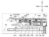
- FIG. 9 is a cross-sectional view showing a state in which the lateral transport belt 15A is lowered from the state of FIG. 29 and the platen 50A is supported on the elevating table 63A.
- FIG. 30 is a cross-sectional view taken along the line IV-IV shown in FIG. 30.
- FIG. 5 is a cross-sectional view showing a state in which the platen 50A is positioned at the print specified position W by the positioning unit 70A from the state of FIG. 30.
- FIG. 3 is a cross-sectional view taken along the line VV in the direction shown in FIG. 32 with the rotation restricting member 91A inserted.
- the printing system 1 shown in FIG. 1 performs pre-processing, printing processing, and post-processing on the printing medium supported by the platen 50 while conveying the platen 50.
- a medium to be printed is a cloth such as a T-shirt.
- An example of the material of the fabric is cotton, polyester, a mixture of cotton and polyester, and the like.
- the printing system 1 includes a pre-processing device 2, printers 3 to 8, a post-processing device 9, a platen transfer mechanism 10, a code reader 95, and the like.
- the pretreatment device 2 is arranged on the front side of the printing system 1 and pretreats the fabric P supported by the platen 50.
- the pretreatment device 2 includes, for example, a coating unit and a heat treatment unit.
- the coating portion sprays the pretreatment agent with a spray, and applies the pretreatment agent to the cloth P supported by the platen 50.
- the pretreatment agent is a base coating agent that is applied before the ink is applied to the fabric P.
- the pretreatment agent is a liquid for forming a film between the fibers of the cloth so that the ink stays on the cloth P more, and is, for example, an aqueous solution containing a resin component and a metal salt such as CaCl 2.
- the heat treatment section heats the pretreatment agent applied to the cloth P at a high temperature. As a result, the fixing of the pretreatment agent to the cloth P is improved, and the image quality of the printed image is improved.
- printers 3 to 5 are arranged in the front-rear direction on the left side, and three printers 6 to 8 are arranged in the front-rear direction on the right side.
- the printers 3 to 8 are inkjet printers that print by ejecting ink from a nozzle of a print head onto the pretreated cloth P supported by the platen 50.
- the aftertreatment device 9 is arranged behind the printers 3 to 8 and heats the printed cloth P supported by the platen 50 at a high temperature to dry the ink, thereby improving the fixing of the ink to the cloth P. Let me.
- the platen transport mechanism 10 transports the platen 50 arranged at the preparation position 100, which will be described later, in the order of the pretreatment device 2, any of the printers 3 to 8, and the post-processing device 9, and returns the platen 50 to the preparation position 100 again.
- the code reader 95 provided at the preparation position 100, which will be described later, reads the identification information for identifying the cloth P from the identification information unit (not shown) provided on the cloth P, and inputs the read identification information into the printing system 1.
- the identification information unit is information for identifying the cloth P, and is, for example, one-dimensional code such as a barcode, two-dimensional code such as a QR code (registered trademark), and three-dimensional code information.
- the identification information may include information such as the type, color, size, print color, and print size of the fabric P.
- the configuration of the platen transport mechanism 10 will be described with reference to FIG.
- the platen transfer mechanism 10 includes a delivery line 201, a left side processing line 202, a right side processing line 203, a first return line 204, and a second return line 205.
- the shipping line 201 extends in a straight line extending in the left-right direction at the foremost part of the printing system 1, and transports the platen 50 toward the left side processing line 202 and the right side processing line 203, which will be described later.
- the delivery line 201 includes transport mechanisms 11 to 13 in this order from the left side.
- the transport mechanism 11 is provided with a preparation position 100.
- the preparation position 100 is a position for attaching the cloth P to the platen 50 and preparing it.
- the transport mechanisms 11 to 13 transport the platen 50 to the right.
- a front end portion of the transport mechanism 14, which will be described later, is arranged between the transport mechanisms 11 and 12.
- a front end portion of the transport mechanism 24, which will be described later, is arranged between the transport mechanisms 12 and 13.
- the left side processing line 202 and the right side processing line 203 are provided side by side in the left-right direction between the shipping line 201 and the first return line 204 described later.
- the left-hand processing line 202 conveys the platen 50 received from the shipping line 201 in the order of the preprocessing device 2, any of the printers 3 to 5, and the post-processing device 9, and delivers the platen 50 to the first return line 204.
- the right-hand processing line 203 conveys the platen 50 received from the shipping line 201 in the order of the preprocessing device 2, any of the printers 6 to 8, and the post-processing device 9, and delivers the platen 50 to the first return line 204.
- the left side processing line 202 includes transfer mechanisms 14 to 23 and print transfer mechanisms 41 to 43.
- the transport mechanism 14 extends rearward from between the transport mechanisms 11 and 12 of the shipping line 201, passes through the inside of the pretreatment device 2, and further extends rearward.
- the transport mechanism 14 receives the platen 50 from the transport mechanism 11, passes through the pretreatment device 2, and transports the platen to the rear.
- the transport mechanism 15 extends from the transport mechanism 14 toward the printer 3 to the left.
- the transport mechanism 15 receives the platen 50 from the transport mechanism 14 and transports the platen 50 toward the printer 3.
- the transport mechanism 16 extends to the left from the printer 3.
- the transport mechanism 16 receives the platen 50 from the printer 3 and transports it to the left.
- the transport mechanism 17 extends to the left from the transport mechanism 14 toward the printer 4 behind the transport mechanism 15.
- the transport mechanism 17 receives the platen 50 from the transport mechanism 14 and transports the platen 50 toward the printer 4.
- the transport mechanism 18 extends to the left from the printer 4.
- the transport mechanism 18 receives the platen 50 from the printer 4 and transports it to the left.
- the transport mechanism 19 extends to the left from the transport mechanism 14 toward the printer 5 behind the transport mechanism 17.
- the transport mechanism 19 receives the platen 50 from the transport mechanism 14 and transports the platen 50 toward the printer 5.
- the transport mechanism 20 extends to the left from the printer 5.
- the transport mechanism 20 receives the platen 50 from the printer 5 and transports it to the left.
- the transport mechanism 21 extends in the front-rear direction on the left side of the printers 3 to 5, and is connected to the left ends of the transport mechanisms 16, 18 and 20, respectively.
- the transport mechanism 21 receives the platen 50 from each of the transport mechanisms 16, 18 and 20, and transports the platen 50 to the rear.
- the transport mechanism 22 extends to the right from the rear end of the transport mechanism 21 behind the printer 5.
- the transport mechanism 22 receives the platen 50 from the transport mechanism 21 and transports it to the right.
- the transport mechanism 23 extends rearward from the right end of the transport mechanism 22, passes through the inside of the aftertreatment device 9, and further extends rearward.
- the transport mechanism 23 receives the platen 50 from the transport mechanism 22, passes through the aftertreatment device 9, and transports the platen to the rear.
- the rear end portion of the transport mechanism 23 is arranged between the transport mechanisms 27 and 28 of the first return line 204, which will be described later.
- the print transport mechanism 41 is provided in the printer 3 and can transport the platen 50 in the left-right direction.
- the print transfer mechanism 41 includes a platen support member 60, a ball screw 3A, a pair of rails 3B, and a transfer motor 137 (see FIG. 12).
- the platen support member 60 receives and supports the platen 50 from the transport mechanism 15.
- the ball screw 3A extends in the left-right direction.
- the pair of rails 3B are provided at positions that sandwich the ball screw 3A in the center, and extend in the left-right direction.
- a nut (not shown) screwed into the ball screw 3A is fixed to the platen support member 60.
- the transport motor 137 rotates the ball screw 3A.
- the structure for transporting the platen support member 60 may be a structure other than the above, and may include, for example, a pair of pulleys, an endless belt, and a motor.
- the endless belt is hung on a pair of pulleys.
- the platen support member 60 is fixed to a part of the endless belt.
- the motor rotates one of the pulleys in the forward and reverse directions, so that the endless belt moves between the pair of pulleys. As a result, the platen support member 60 can move together with the endless belt.
- the printer 4 is provided with a print transfer mechanism 42, and the printer 5 is provided with a print transfer mechanism 43. Since the print transfer mechanism 42 and 43 have the same configuration as the print transfer mechanism 41, description thereof will be omitted.
- the right-hand processing line 203 includes a transport mechanism 24 on the front end side and a transport mechanism 25 on the rear end side.
- the transport mechanism 24 has the same structure as the transport mechanism 14 of the left processing line 202.
- the front end of the transport mechanism 24 is arranged between the transport mechanisms 12 and 13 of the shipping line 201.
- the transport mechanism 25 has the same structure as the transport mechanism 23 of the left processing line 202.
- the rear end portion of the transport mechanism 25 is arranged between the transport mechanisms 26 and 27 of the first return line 204, which will be described later.
- the first return line 204 extends linearly in the left-right direction at the rearmost portion of the printing system 1, and returns the platen 50 received from the left processing line 202 and the right processing line 203 toward the left.
- the first return line 204 includes transfer mechanisms 26 to 28 in this order from the right side.
- the transport mechanisms 26 to 28 transport the platen 50 to the left.
- the rear end of the transport mechanism 23 of the left processing line 202 is arranged between the transport mechanisms 27 and 28.
- the rear end of the transport mechanism 25 of the right processing line 203 is arranged between the transport mechanisms 26 and 27.
- the second return line 205 extends linearly in the front-rear direction, returns the platen 50 received from the first return line 204 forward, and delivers it to the transport mechanism 11.
- the second return line 205 includes a transport mechanism 29.
- the transport mechanism 29 transports the platen 50 forward.
- the platen 50 delivered to the transport mechanism 11 returns to the preparation position 100 by the transport mechanism 11.
- the transport mechanism 13 of the shipping line 201 may transport the platen 50 toward another processing line (not shown).
- the other processing lines may have the same configuration as the left processing line 202 and the right processing line 203.
- the transport mechanism 26 of the first return line 204 may transport the platen 50 received from another processing line (not shown) to the left.
- the belt configuration of the platen transport mechanism 10 will be described with reference to FIG. Since the belt configurations of the left processing line 202 and the right processing line 203 are common except that they are symmetrical, the belt configuration of the left processing line 202 will be described, and the description of the belt configuration of the right processing line 203 will be omitted.
- the transport mechanisms 11 to 13 include a pair of horizontal belts 11A to 13A.
- the horizontal belts 11A to 13A are provided at both ends in a direction orthogonal to the transport direction of the transport mechanisms 11 to 13 in a plan view, and transport the platen 50 to the right.
- the transport mechanism 14 includes a pair of vertical belts 14A and a pair of horizontal lifting belts 14B to 14E.
- the pair of vertical belts 14A are provided at both ends in a direction orthogonal to the transport direction of the transport mechanism 14 in a plan view.
- the pair of vertical belts 14A convey the platen 50 rearward.
- the pair of horizontal lifting belts 14B to 14E are arranged between the pair of vertical belts 14A.
- the pair of lateral lifting belts 14B are provided so as to be able to move up and down at the front end portion of the transport mechanism 14.
- the pair of lateral lifting belts 14B convey the platen 50 to the right.
- the pair of lateral lifting belts 14C are provided so as to be able to move up and down on the right side of the transport mechanism 15.
- the pair of lateral lifting belts 14D are provided so as to be able to move up and down on the right side of the transport mechanism 17.
- the pair of lateral lifting belts 14E are provided so as to be able to move up and down on the right side of the transport mechanism 19.
- the pair of lateral lifting belts 14C to 14E convey the platen 50 to the left.
- the transport mechanisms 15 to 20 include a pair of lateral transport belts 15A to 20A.
- the pair of lateral transport belts 15A to 20A are provided so as to be able to move up and down at both ends in a direction orthogonal to the transport direction of the transport mechanisms 15 to 20 in a plan view.
- the transport mechanism 21 includes a pair of vertical belts 21A and a pair of horizontal lifting belts 21B to 21E.
- the pair of vertical belts 21A are provided at both ends in a direction orthogonal to the transport direction of the transport mechanism 21 in a plan view.
- the pair of vertical belts 21A convey the platen 50 rearward.
- the pair of horizontal lifting belts 21B to 21E are arranged between the pair of vertical belts 21A, and are provided so as to be able to move up and down on the left sides of the transport mechanisms 16, 18, 20, and 22, respectively.
- the pair of lateral elevating belts 21B to 21D convey the platen 50 to the left, and the pair of lateral elevating belts 21E convey the platen 50 to the right.
- the transport mechanism 22 includes a pair of horizontal belts 22A.
- the pair of horizontal belts 22A are provided at both ends in a direction orthogonal to the transport direction of the transport mechanism 22 in a plan view, and transport the platen 50 toward the right.
- the transport mechanism 23 includes a pair of vertical belts 23A and a pair of horizontal elevating belts 23B and 23C.
- the pair of vertical belts 23A are provided at both ends in a direction orthogonal to the transport direction of the transport mechanism 23 in a plan view.
- the pair of vertical belts 23A convey the platen 50 rearward.
- the pair of horizontal lifting belts 23B and 23C are arranged between the pair of vertical belts 23A, and are provided so as to be able to move up and down on the right side of the transport mechanisms 22 and 28, respectively.
- the pair of lateral elevating belts 23B conveys the platen 50 to the right
- the pair of lateral elevating belts 23C conveys the platen 50 to the left.
- the transport mechanisms 26 to 28 include a pair of horizontal belts 26A to 28A extending in the transport direction, and transport the platen 50 in the transport direction in each transport mechanism 26 to 28, that is, to the left.
- the transport mechanism 29 includes a pair of vertical belts 29A and a pair of horizontal elevating belts 29B and 29C.
- the pair of vertical belts 29A are provided at both ends in a direction orthogonal to the transport direction of the transport mechanism 29 in a plan view.
- the pair of vertical belts 29A convey the platen 50 forward.
- the pair of horizontal lifting belts 29B and 29C are arranged between the pair of vertical belts 29A, and are provided so as to be able to move up and down on the left side of the transport mechanisms 28 and 11, respectively.
- the pair of lateral elevating belts 29B convey the platen 50 to the left
- the pair of lateral elevating belts 29C convey the platen 50 to the right.
- the platen transport mechanism 10 includes a vertical belt motor 131, a horizontal belt motor 132, a horizontal lift belt motor 133, a horizontal lift belt motor 134, a first lift motor 135, a second lift motor 136, and a transport motor 137. , Elevating motor 69 and the like are further provided.
- the vertical belt motor 131 is provided corresponding to each of the vertical belts 14A, 21A, 23A, and 29A, and drives each belt.
- the horizontal belt motor 132 is provided corresponding to each of the horizontal belts 11A to 13A, 22A, and 26A to 28A, and drives each belt.
- the lateral elevating belt motor 133 is provided corresponding to each of the lateral elevating belts 14B to 14E, 21B to 21E, 23B, 23C, 29B, and 29C, and drives each belt.
- the lateral transport belt motor 134 is provided corresponding to each of the lateral transport belts 15A to 20A, and drives each belt.
- the first elevating motor 135 is provided corresponding to each of the lateral elevating belts 14B to 14E, 21B to 21E, 23B, 23C, 29B, and 29C, and elevates and elevates each belt.
- the second elevating motor 136 is provided corresponding to each of the lateral transport belts 15A to 20A, and elevates and elevates each belt.
- a sensor (not shown) is arranged at the position of each lateral lifting belt.
- the sensor can detect the platen 50 on the corresponding lateral lifting belt.
- the CPU 101 controls driving and raising / lowering of each belt based on the detection signals from these sensors.
- the lateral elevating belt 14B is arranged at the same height position as the lateral elevating belt 11A, and the platen 50 is delivered from the lateral belt 11A to the lateral elevating belt 14B. After that, the lateral elevating belt 14B stops driving and descends.
- the vertical belt 14A is driven.
- the platen 50 is placed on the vertical belt 14A and conveyed rearward.
- the platen 50 passes through the pretreatment device 2 and is further conveyed rearward.
- the drive of the vertical belt 14A is stopped and the horizontal elevating belt 14C starts to ascend.
- the horizontal elevating belt 14C rises above the vertical belt 14A and stops at the same height position as the horizontal transport belt 15A.
- the lateral transfer belt 15A and the lateral elevating belt 14C are driven, and the platen 50 is delivered from the lateral elevating belt 14C to the lateral transfer belt 15A.
- the lateral transfer belt 15A is driven, and the platen 50 is conveyed toward the printer 3.
- the platen 50 is delivered from the lateral transport belt 15A to the platen support member 60 provided inside the printer 3. The specific procedure for the platen 50 to be delivered from the lateral transport belt 15A to the platen support member 60 will be described later.
- the platen 50 is supported by the platen support member 60, is conveyed to the left along the pair of rails 3B, and is printed inside the printer 3. After printing, the platen 50 is conveyed to the left from the inside of the printer 3 and stops at the left end position of the pair of rails 3B.
- the lateral transport belt 16A rises, the platen 50 is lifted by the lateral transport belt 16A and separated from the platen support member 60.
- the lateral elevating belt 21B of the transport mechanism 21 rises to the same height position as the lateral transport belt 16A.
- the lateral transfer belt 16A and the lateral elevating belt 21B are driven, and the platen 50 is delivered from the lateral transfer belt 16A to the lateral elevating belt 21B.
- the lateral elevating belt 21B stops driving and descends. At the same time, the vertical belt 21A of the transport mechanism 21 is driven. As the lateral elevating belt 21B descends from the vertical belt 21A, the platen 50 is placed on the vertical belt 21A and conveyed rearward.
- the platen 50 is conveyed in the order of the conveying mechanisms 21, 22 and 23 by the same delivery operation as described above, and passes through the aftertreatment device 9.
- the platen 50 that has passed through the aftertreatment device 9 is delivered from the left processing line 202 to the first return line 204, and from the first return line 204 to the second return line 205 in this order, and is delivered to the transport mechanism 11 of the delivery line 201. Then, it returns to the preparation position 100.
- step A shown in FIG. 1 is a step of transporting the platen 50 in the order of the transport mechanism 15, the printer 3, and the transport mechanism 16.
- the right side of the paper surface (upstream side in the transport direction) is the front of the printer 3, and the left side of the paper surface (downstream side in the transport direction) is the printer.
- the rear of the paper 3, the upper part of the paper surface is the right side of the printer 3, and the lower part of the paper surface is the left side of the printer 3.
- the orientation of the platen 50 will be described in the directions shown in FIGS. 2 to 5 and 14 to 20 following the direction in step A.
- the same steps as in step A are provided in the printers 4 to 8, but in the first embodiment, step A will be described as an example.
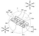
- the platen 50 includes a pedestal 51, a right side plate 52, a left side plate 53, a lower plate 54, an upper plate 55, and a mounting plate 56.
- the pedestal 51 is formed in a rectangular shape in a plan view.
- a pair of support members 570 and 580 are fixed at positions separated from each other in the left-right direction at substantially the center of the upper surface of the pedestal 51 in the left-right direction.
- the right side plate 52 is formed in an inverted L shape when viewed from the right side, and includes an upward extending portion 521 and a front extending portion 522.
- the upward extension portion 521 extends in the vertical direction from the pedestal 51.
- the front extension portion 522 extends forward from the upper portion of the upper extension portion 521 and extends in the front-rear direction.
- the front end of the front extension 522 slopes rearward from the top to the bottom.
- the right side plate 52 is arranged on the left side of the support member 570 shown in FIG.
- the lower end of the upper extending portion 521 of the right side plate 52 is fixed to the left surface of the support member 570 with screws (not shown). As a result, the right side plate 52 is erected on the upper surface of the pedestal 51.
- the left side plate 53 includes an upward extending portion 531 and a front extending portion 532, and is formed in an L shape when viewed from the left side, similarly to the right side plate 52.
- the front end of the front extension 532 slopes rearward from the top to the bottom.
- the left side plate 53 is arranged on the right side of the support member 580.
- the lower end of the upper extending portion 531 of the left side plate 53 is fixed to the right surface of the support member 580 with screws (not shown). As a result, the left side plate 53 is erected on the upper surface of the pedestal 51 in parallel with the right side plate 52.
- the lower plate 54 connects the front side portion of the lower end portion of the front extension portion 522 of the right side plate 52 and the front side portion of the lower end portion of the front extension portion 532 of the left side plate 53.
- the upper plate 55 connects the upper end of the right side plate 52 and the upper end of the left side plate 53, and is provided in parallel with the lower plate 54.
- the upper plate 55 has a substantially rectangular shape in a plan view smaller than the pedestal 51.
- the mounting plate 56 is fixed to the upper surface of the upper plate 55 via a spacer 55A which is a metal plate.
- the mounting plate 56 is formed in a substantially rectangular shape in a plan view, which is smaller than the pedestal 51 and larger than the upper plate 55.
- the cloth P is attached to the upper surface of the attachment plate 56.
- a hanging prevention plate 56A is provided behind the platen 50.
- the sagging prevention plate 56A extends below the mounting plate 56 from the rear end of the spacer 55A to the rear of the rear end of the mounting plate 56, and further extends upward from there.
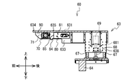
- the platen support member 60 includes a base 61, a vertical column 62, an elevating table 63, a first positioning cylinder 70, a second positioning cylinder 80, and a proximity sensor 90.
- the base 61 is formed in a substantially rectangular shape that is long in the left-right direction in a plan view.
- a guided portion 64 is provided at the central portion in the left-right direction on the lower surface of the base 61.
- the guided portion 64 is formed in a U-shaped cross section that extends in the front-rear direction and opens downward.
- a ball screw 3A (see FIGS. 1 and 6) is inserted into the guided portion 64.
- Guided portions 65 and 66 are provided at both ends in the left-right direction on the lower surface of the base 61.
- the guided portions 65 and 66 are formed in a U-shaped cross section that extends in the front-rear direction and opens downward.
- the guided portions 65 and 66 are movably supported along the pair of rails 3B. Therefore, the base 61 can be accurately moved in the front-rear direction along the pair of rails 3B.
- the vertical column 62 is erected at a substantially central portion in the left-right direction on the upper surface of the base 61, and is formed in a substantially rectangular parallelepiped shape extending upward.
- a pair of rails 67, a ball screw 68, and an elevating motor 69 are provided on the right surface of the vertical column 62.
- the pair of rails 67 are provided along both front and rear ends of the right side of the vertical column 62 and extend in the vertical direction.
- the ball screw 68 is provided between the pair of rails 67 and is rotatably supported by the shaft.
- a nut 681 is screwed into the ball screw 68.
- the nut 681 is fixed to a hanging plate 638 provided on the elevating table 63, which will be described later.
- the elevating motor 69 is provided above the ball screw 68.
- the output shaft of the elevating motor 69 projects downward and is connected to the upper end of the ball screw 68.
- the elevating motor 69 is not limited to this, and may be located below the ball screw 68, its output shaft may protrude upward, and may be connected to the ball screw 68 via a pulley and a belt (not shown).
- the ball screw 68 may be a feed screw, for example, a trapezium screw.
- the elevating table 63 is formed in a substantially box shape having an open lower surface, and includes an upper plate 631, a right plate 632, a left plate 633, and a hanging plate 638 (see FIG. 7).
- the upper plate 631 has a substantially rectangular shape that is long in the front-rear direction in a plan view.
- Three convex portions 634 to 636 are provided on the front side of the upper surface of the upper plate 631.
- the convex portion 634 is provided at a substantially central portion in the left-right direction at the front end portion of the upper surface of the upper plate 631.
- the convex portion 635 is provided behind the convex portion 634 and near the right end portion of the upper surface of the upper plate 631.
- the convex portion 636 is provided behind the convex portion 634 and near the left end portion of the upper surface of the upper plate 631. That is, the three convex portions 634 to 636 are arranged at each apex of the plan view triangle on the upper surface of the upper plate 631.
- the convex portions 634 to 636 have a rib shape that is long in the front-rear direction.
- the right plate 632 extends downward from the right end of the upper plate 631.
- the left plate 633 extends downward from the left end of the upper plate 631.
- An opening 637 is provided on the front end side of the left plate 633.
- the hanging plate 638 hangs downward from the inside of the elevating table 63, and is formed in a substantially rectangular shape when viewed from the right side.
- the hanging plate 638 supports the elevating table 63.
- the hanging plate 638 is supported on the right side of the vertical column 62 so as to be movable in the vertical direction along the pair of rails 67.
- a nut 681 is fixed to the left surface of the hanging plate 638.
- the first positioning cylinder 70 is arranged inside the outer shape of the elevating table 63 in a plan view, and is located on the front end side of the lower surface of the upper plate 631 and on the front end side of the inner surface of the right plate 632. It is fixed in close contact with each other.
- the first positioning cylinder 70 extends the tip of the horizontal pin 75 (see FIG. 10), which will be described later, to the left, and contacts and presses the left side plate 53 of the platen 50 placed on the elevating table 63.
- the platen 50 is positioned horizontally.
- the second positioning cylinder 80 is arranged inside the outer shape of the elevating table 63 in a plan view.
- the second positioning cylinder 80 is fixed at a position adjacent to the rear side of the first positioning cylinder 70 on the lower surface of the upper plate 631, and is arranged inside the outer shape of the elevating table 63 like the first positioning cylinder 70. ..
- the second positioning cylinder 80 positions the platen 50 in the vertical direction by moving the pin 84, which will be described later, downward and contacting and pressing the upper surface of the lower plate 54 of the platen 50 placed on the elevating table 63. To do.
- the proximity sensor 90 is fixed to the front end side on the lower surface of the upper plate 631 of the elevating table 63, and is arranged at a position hidden inside the outer shape of the elevating table 63 in a plan view.
- the proximity sensor 90 can detect the platen 50 placed on the elevating table 63.
- the proximity sensor 90 and the proximity sensor 79 described later may be, for example, an inductive proximity sensor, a capacitance type proximity sensor, a magnetic proximity sensor, or the like.
- the structure of the first positioning cylinder 70 will be described with reference to FIG.
- the first positioning cylinder 70 is an air cylinder and includes a main body portion 71, a cylindrical portion 73, a horizontal pin 75, a proximity sensor 79, and the like.
- a cylinder tube (not shown) having a piston is provided inside the substantially rectangular parallelepiped main body 71.
- the horizontal pin 75 is made of metal and has a substantially cylindrical shape extending in the left-right direction.
- a tapered portion 751 is provided at the left tip portion of the horizontal pin 75.
- the tapered portion 751 has a substantially conical shape whose diameter decreases toward the left.
- the diameter R of the tapered portion 751 (see FIG. 19) is smaller than the large diameter r1 of the insertion hole 59 described later provided in the left side plate 53 of the platen 50 and larger than the small diameter r2.
- the horizontal pin 75 can move back and forth in the left-right direction inside the cylindrical portion 73 by the reciprocating motion of the piston.
- the first positioning cylinder 70 is fixed to the inside of the elevating table 63 with screws or the like in a state where the right surface of the main body 71 is in close contact with the upper part of the inner surface of the right plate 632 of the elevating table 63.
- the cylindrical portion 73 is arranged inside the opening 637 provided in the left plate 633 of the elevating table 63 (see FIG. 6).
- the proximity sensor 79 is provided at a predetermined position inside the main body 71.
- the predetermined position is, for example, a position close to the piston in the air tube when the horizontal pin 75 is fully extended to the left.
- the proximity sensor 79 detects that the pistons are close to each other.
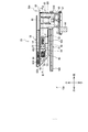
- the structure of the second positioning cylinder 80 will be described with reference to FIG.
- the second positioning cylinder 80 includes a support member 81, a main body 82, a cylinder rod 83, a pin 84, a support shaft 86, a main body support shaft 818, a proximity sensor 89, and the like.
- the support member 81 is formed in a substantially U shape that opens toward the front in a plan view.
- the support member 81 includes a rear plate 811, a right plate 812, and a left plate 813.
- the right plate 812 extends forward from the right end of the rear plate 811.
- An opening 817 is provided at a position slightly behind the center of the right plate 812.
- a shaft support hole 814 is provided at a position on the right plate 812 on the front side of the opening 817 and near the lower end.
- Fixing pieces 815 and 816 are provided at the upper end of the right plate 812 apart from each other in the front-rear direction. The fixing pieces 815 and 816 project to the right from the upper end of the right plate 812.
- the left plate 813 extends forward from the left end of the rear plate 811.
- a shaft support hole (not shown) is provided at a position of the left plate 813 facing the shaft support hole 814 of the right plate 812.
- the support shaft 86 extends in the left-right direction and is inserted and fixed in the shaft support hole 814 of the right plate 812 and the shaft support hole of the left plate 813.
- the main body support shaft 818 also extends in the left-right direction, and has a shaft support hole (not shown) provided at a position close to the rear side of the opening 817 in the right plate 812, and a rear end side of the left plate 813, which is the right plate.
- Fixing pieces 815 and 816 are also provided at the upper end of the left plate 813 apart from each other in the front-rear direction.
- the fixing pieces 815 and 816 project to the left from the upper end of the left plate 813.
- the fixing pieces 815 and 816 of the right plate 812 and the left plate 813 are fixed to the lower surface of the upper plate 631 of the elevating table 63 with screws. As a result, the support member 81 is fixed to the lower surface of the upper plate 631.
- the main body 82 is arranged inside the support member 81, and is swingably supported by the main body support shaft 818.
- the cylinder rod 83 is provided so as to be retractable in the front-rear direction from a substantially central portion on the front surface of the main body portion 82, and is connected to a piston in the cylinder tube.
- a U-shaped portion 831 is fixed to the tip end portion of the cylinder rod 83.
- the U-shaped portion 831 has a substantially U-shape that opens toward the front in a plan view.
- a support shaft 832 extending in the left-right direction is supported inside the U-shaped portion 831.
- the pin 84 includes a base portion 841 and a cylindrical portion 842.
- the base 841 has a substantially rectangular parallelepiped shape.
- the cylindrical portion 842 extends obliquely downward with respect to the front from the side surface of the base portion 841.
- the R portion 851 may be provided at the corner of the outer periphery of the tip portion 85 of the cylindrical portion 842.
- the R portion 851 may be formed in an arc shape so that the diameter decreases toward the tip.
- a part of the base portion 841 is arranged inside the U-shaped portion 831 of the cylinder rod 83.
- the base portion 841 is swingably supported with respect to the support shaft 86 fixed to the support member 81.
- the base portion 841 is swingably supported above the support shaft 86 with respect to the support shaft 832 of the U-shaped portion 831. Therefore, the main body 82 and the pin 84 are supported by the main body support shaft 818 and the support shaft 86 inside the support member 81.
- the proximity sensor 89 is provided at a predetermined position inside the main body 82.
- the predetermined position is, for example, a position close to the piston in the air tube when the cylinder rod 83 is fully extended forward.
- the proximity sensor 89 detects that the pistons are close to each other.
- the electrical configuration of the printing system 1 will be described with reference to FIG.
- the printing system 1 includes a CPU 101, a ROM 102, a RAM 103, a storage unit 104, a pre-processing device 2, printers 3 to 8, a post-processing device 9, an operation unit 110, an input / output unit 111, proximity sensors 79, 89, 90, and a foreign matter detection sensor.
- 93, code reader 95, drive circuits 121 to 130, vertical belt motor 131, horizontal belt motor 132, horizontal lifting belt motor 133, horizontal transport belt motor 134, first lifting motor 135, second lifting motor 136, transport motor 137, Elevating motor 69, first positioning cylinder 70, second positioning cylinder 80 and the like are provided and connected to each other via a bus.
- the CPU 101 controls the operation of the printing system 1.
- the ROM 102 stores various programs.
- the RAM 103 is a working memory and temporarily stores various information.
- the storage unit 104 is a non-volatile flash memory and stores various information.
- the operation unit 110 receives various inputs by the operator.
- the operation unit 110 may be a touch panel (not shown), and may display various information in addition to receiving various inputs.
- the input / output unit 111 includes an SD memory card slot, a USB (registered trademark) port, a serial port of another standard, and the like.
- the drive circuit 121 controls the operation of the vertical belt motor 131 based on the control command from the CPU 101.
- the drive circuit 122 controls the operation of the horizontal belt motor 132 based on the control command from the CPU 101.
- the drive circuit 123 controls the operation of the lateral lifting belt motor 133 based on the control command from the CPU 101.
- the drive circuit 124 controls the operation of the lateral transport belt motor 134 based on the control command from the CPU 101.
- the drive circuit 125 controls the operation of the first elevating motor 135 based on the control command from the CPU 101.
- the drive circuit 126 controls the operation of the second elevating motor 136 based on the control command from the CPU 101.
- the drive circuit 127 controls the operation of the transfer motor 137 based on the control command from the CPU 101.
- the drive circuit 128 controls the operation of the elevating motor 69 based on the control command from the CPU 101.
- the drive circuit 129 controls the operation of the first positioning cylinder 70 based on the control command from the CPU 101.
- the drive circuit 130 controls the operation of the second positioning cylinder 80 based on the control command from the CPU 101.
- a stepping motor may be used as each motor constituting the platen transport mechanism 10. In that case, by connecting an encoder to each motor and transmitting the position information of the motor from each encoder to the CPU 101, the CPU 101 can recognize the position of each motor.
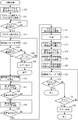
- the printing process will be described with reference to FIGS. 13 to 20.
- the platen transport mechanism 10 transports the platen 50 arranged at the preparation position 100 in the order of the pretreatment device 2, the printers 3 to 8, and the post-processing device 9, and returns the platen 50 to the preparation position 100 again.
- the platen 50 to which the cloth P is attached is delivered from the transfer mechanism 15 to the platen support member 60, printed inside the printer 3, and then transferred from the platen support member 60 to the transfer mechanism 16. This will be described in detail.
- the process described later is executed by the CPU 101 reading the control program stored in the ROM 102.
- the elevating table 63 is arranged at the first position z1 in the vertical direction.
- the initial position is a position in the front-rear direction when the platen support member 60 receives the platen 50, for example, a front end position of the movable range of the platen support member 60 on the pair of rails 3B.
- the position of the lift table 63 is lower than that of the platen 50, so that the platen 50
- the rear ends of the lower plate 54 collide with the front ends of the right plate 632 and the left plate 633 of the elevating table 63, respectively.
- the elevating table 63 is inserted only halfway into the space surrounded by the right side plate 52, the left side surface plate 53, the lower plate 54, and the upper plate 55 of the platen 50. If positioning is performed by the first positioning cylinder 70 and the second positioning cylinder 80 in that state, the platen 50 cannot be positioned at the specified printing position W, and the printing position shifts with respect to the fabric P. Will occur.
- the CPU 101 raises the elevating table 63 from the first position z1 to the second position z2 (S10).
- the CPU 101 drives the lateral transport belt 15A and transports the platen 50 toward the elevating table 63 (S11). Since the elevating table 63 is located at the second position z2, the elevating table 63 interferes with the space surrounded by the right side plate 52, the left side plate 53, the lower plate 54, and the upper plate 55 of the platen 50 from the tip side. Is inserted without (see FIG. 16).
- the fabric P does not block the space surrounded by the right side plate 52, the left side plate 53, the lower plate 54, and the upper plate 55 by the hanging prevention plate 56A, so that the elevating table 63 does not come into contact with the fabric P. Will be inserted.
- the CPU 101 determines whether the insertion of the platen 50 is completed (S12).
- the insertion completion position of the platen 50 is, for example, a predetermined position on the downstream side in the transport direction of the lateral transport belt 15A.
- a limiter switch is provided at a predetermined position.
- the CPU 101 determines that the insertion of the platen 50 is completed.
- the CPU 101 returns to S12 and continues to convey the platen 50 toward the elevating table 63.
- the CPU 101 stops driving the lateral transfer belt motor 134 of the lateral transfer belt 15A, and stops the transfer of the platen 50 (S13). ..
- the CPU 101 lowers the lateral transport belt 15A in order to mount and support the platen 50 on the upper surface of the upper plate 631 of the elevating table 63 (S14).
- the platen 50 descends together with the lateral transport belt 15A.
- the lower surface of the upper plate 55 of the platen 50 comes into contact with the three convex portions 634 to 636 provided on the upper plate 631 of the elevating table 63, and is supported in a state of being placed by gravity.
- the CPU 101 determines whether the platen 50 is placed on the elevating table 63 (S15).
- the proximity sensor 90 fixed to the upper plate 631 of the elevating table 63 is supported.
- Platen 50 is detected.
- the proximity sensor 90 transmits the detection signal to the CPU 101.
- the detection signal is not received from the proximity sensor 90, the platen 50 is away from the elevating table 63 (S15: NO), so that the CPU 101 determines whether the elapsed time from lowering the lateral transport belt 15A is time over. (S29). If the elapsed time is not over (S29: NO), the CPU 101 returns to S14 and continues to lower the lateral transport belt 15A. When the elapsed time is over (S29: YES), the CPU 101 outputs an error (S30) and ends the transfer control process.
- the platen 50 was separated from the lateral transport belt 15A and placed on the elevating table 63 (S15: YES).
- the drive is stopped, and the lowering of the lateral transport belt 15A is stopped (S16).
- the following operations may be performed.
- the CPU 101 rotates the second elevating motor 136 by a predetermined amount, lowers the lateral transport belt 15A by a predetermined amount, and stops the lowering of the lateral transport belt 15A.
- the CPU 101 determines whether or not the detection signal has been received from the proximity sensor 90. When the CPU 101 determines that the detection signal has been received, it determines that the platen 50 is placed on the elevating table 63.
- the CPU 101 If it is determined that the detection signal has not been received, the CPU 101 outputs an error. Since the three convex portions 634 to 636 supporting the platen 50 are arranged at each apex of the plan view triangle on the upper plate 631 of the elevating table 63 (see FIG. 6), the convex portions 634 to 636 are the platen 50. Can be stably supported.
- the number of convex portions provided on the upper plate 631 of the elevating table 63 is not limited to three, and may be more than three, and the arrangement of the convex portions can be freely changed.
- the convex portions 634 to 636 are omitted from the upper surface of the upper plate 631 of the elevating table 63 and the lower surface of the upper plate 55 of the platen 50 is directly placed on the upper surface of the upper plate 631, the lower surface of the upper plate 55 If the upper surface of the upper plate 631 is not parallel to each other, the lower surface of the upper plate 55 will not be in close contact with the upper surface of the upper plate 631, and the platen 50 will rattle with respect to the elevating table 63 and will not be supported at a constant height position. ..
- the lower surface of the upper plate 55 of the platen 50 is placed on the convex portions 634 to 636, so that the upper plate 55 of the platen 50 is constant with respect to the upper plate 631 of the elevating table 63. Can be stably supported at a high position.
- the CPU 101 first operates the first positioning cylinder 70 in order to position the platen 50 at the print regulation position W (see FIG. 18) in the left-right direction and the front-back direction in the printer 3 (S17).
- the platen 50 positioned at the print regulation position W moves in the extending direction of the rail 3B (FIG. 1: left-right direction, FIG. 2, FIG. 18: front-rear direction), and is printed inside the printer 3.
- the platen 50 must match the position of the platen 50 with the reference position when printing inside the printer 3.
- the position of the platen 50 changes in the front-rear direction shown in FIG. 18, but does not change in the left-right direction. That is, the reference position and the print regulation position W at the time of printing change in the front-rear direction, but do not change in the left-right direction.
- the printer 3 has a carriage that reciprocates with the left-right direction shown in FIG. 18 as the main scanning direction, the print regulation position W in the left-right direction is within the movement range of the carriage on which the inkjet head is mounted. Further, the printer 3 recognizes the position in the front-rear direction of the platen support member 60 that supports the platen 50 and forms an image.
- the platen 50 needs to be below the image forming portion provided in the printer 3 so as not to come into contact with the platen 50.
- the image forming portion is an inkjet head
- the landing distance changes according to the distance between the platen 50 and the inkjet head. Therefore, if the vertical position of the platen 50 changes, the printer 3 cannot form a desired image. That is, the levelness of the platen 50 needs to be maintained so that the distance between each position of the platen 50 and the inkjet head is within a predetermined range.
- the vertical position of the platen 50 may be adjusted automatically or manually depending on the thickness of the fabric P, but it is desirable to determine the position of the platen 50 before the adjustment.
- the distance between the platen 50 and the image forming portion is preferably 1 mm to 100 mm. Therefore, it is necessary to position the platen 50 with respect to the platen support member 60 so that the position of the platen 50 does not change in the front-back, left-right, up-down directions each time the platen support member 60 is handed over.
- the position of the platen 50 with respect to the platen support member 60 is defined as the print regulation position W.
- the print regulation position W is, for example, a predetermined position with respect to the platen support member 60, and is a reference position at the time of printing by the printer 3.
- the CPU 101 positions the platen 50 in the front-rear direction, the left-right direction, and the up-down direction with respect to the elevating table 63 of the platen support member 60 arranged at the receiving position in the front-rear direction. Positioned.
- a through hole 57 is provided on the front end side of the front extending portion 532 of the left side plate 53 of the platen 50.
- the through hole 57 has a substantially rectangular shape when viewed from the left side, and penetrates the left side plate 53 in the left-right direction.
- a recess 57A formed in a concave shape toward the left is provided around the through hole 57.
- a metal contact plate 58 is fitted inside the recess 57A and fixed with four screws 97.
- An insertion hole 59 is provided at substantially the center of the contact plate 58.
- the insertion hole 59 has an oval shape that is longer in the vertical direction than in the front-rear direction, and has a large diameter r1 in the vertical direction and a small diameter r2 in the front-rear direction.
- the insertion hole 59 communicates with the through hole 57.
- a tapered portion 591 is provided on the outer circumference of the insertion hole 59.
- the tapered portion 591 is an oval ring having the same width along the outer circumference of the insertion hole 59, and is inclined so that the thickness in the left-right direction becomes thinner toward the insertion hole 59 side.
- the horizontal pin 75 extends from the cylindrical portion 73 of the first positioning cylinder 70 toward the insertion hole 59 of the left side plate 53 of the platen 50 (see FIG. 6). As the horizontal pin 75 extends toward the insertion hole 59, the tip of the tapered portion 751 is inserted into the insertion hole 59, and the tapered portion 751 comes into contact with the tapered portion 591 of the insertion hole 59. As described above, the diameter R of the tapered portion 751 of the horizontal pin 75 has a diameter R smaller than the large diameter r1 of the insertion hole 59 and larger than the small diameter r2.
- the tapered portion 751 contacts the pair of both edge portions 592 facing each other in the front-rear direction among the tapered portions 591 of the insertion hole 59, and does not contact the upper edge portion and the lower edge portion.
- the platen 50 can be positioned in the vertical direction when the second positioning cylinder 80, which will be described later, is operated.
- the tapered portion 751 presses to the left in a state of being in contact with one of both edge portions 592 of the insertion hole 59.
- the tapered portion 751 of the horizontal pin 75 and the tapered portion 591 of the insertion hole 59 are both inclined so as to spread in the vertical direction and the front-rear direction from the left side to the right side. Therefore, even if the center of the insertion hole 59 on the platen 50 side is displaced in the front-rear direction with respect to the tip of the horizontal pin 75, the tapered portion 751 presses one of the both edge portions 592 of the tapered portion 591 to the left.
- the tapered portion 591 slides along the slope of the tapered portion 751 and moves so that the center of the insertion hole 59 coincides with the position of the tip of the horizontal pin 75 in the front-rear direction.
- the platen 50 moves in the front-rear direction with reference to the position of the horizontal pin 75.
- the platen 50 moves to the left with respect to the elevating table 63.
- the inner surface (left surface) of the right side plate 52 of the platen 50 comes into contact with the outer surface (right surface) of the right plate 632 of the elevating table 63. Therefore, since the platen 50 cannot move not only in the front-rear direction but also in the left-right direction, the platen 50 is firmly positioned in the left-right direction with respect to the elevating table 63.
- the tip portion of the tapered portion 751 of the horizontal pin 75 is assumed to be the insertion hole 59 in the front-rear direction. Even if it is deviated from the center, the tapered portion 591 slides along the slope of the tapered portion 751. As a result, the horizontal pin 75 is guided toward the center of the insertion hole 59. Then, the tapered portion 751 is pressed to the left in a state of being in contact with the pair of both edge portions 592 of the insertion hole 59. Therefore, since the platen 50 cannot move in the front-rear direction, it is firmly positioned with respect to the elevating table 63 in the front-rear direction at the same time as the positioning in the left-right direction.
- the CPU 101 determines whether the positioning in the left-right direction and the front-back direction is completed (S18).
- the proximity sensor 79 (see FIG. 10) provided in the first positioning cylinder 70 detects the piston when the horizontal pin 75 is fully extended to the left, and transmits a detection signal to the CPU 101.
- the horizontal pin 75 is fully extended to the left, the positioning of the platen 50 in the left-right direction and the front-back direction is completed. Since the positioning of the platen 50 in the left-right direction and the front-back direction is not completed until the detection signal from the proximity sensor 79 is received (S18: NO), the CPU 101 returns to S17, and the horizontal pin 75 continues to the left. Stretch.
- the detection signal is received from the proximity sensor 79, the positioning of the platen 50 in the left-right direction and the front-back direction is completed (S18: YES), so that the CPU 101 subsequently operates the second positioning cylinder 80 (S19).
- the cylinder rod 83 extends forward from the center of the left surface of the main body 82 of the second positioning cylinder 80.
- the support shaft 832 of the U-shaped portion 831 pushes the base 841 of the pin 84 forward.
- the tip portion 85 of the pin 84 also rotates downward with respect to the support shaft 86.
- the R portion 851 of the tip portion 85 of the pin 84 comes into contact with the upper surface of the lower plate 54 of the platen 50. At this time, the pin 84 is pressing the upper surface of the lower plate 54.
- the lower surface of the upper plate 55 of the platen 50 is already in contact with the convex portions 634 to 636 of the upper plate 631 of the elevating table 63. Therefore, when the lower plate 54 is pressed downward by the tip portion 85 of the pin 84, the platen 50 moves downward with respect to the elevating table 63 so as to correct the deviation in the vertical direction. Then, the upper plate 55 of the platen 50 is in a state of being pressed from above against the convex portions 634 to 636 of the elevating table 63. As a result, the platen 50 is firmly positioned with respect to the elevating table 63 in the vertical direction. Then, since the platen 50 is positioned in the horizontal direction, the front-rear direction, and the vertical direction with respect to the elevating table 63, the platen 50 is accurately positioned at the print regulation position W of the printer 3.
- the CPU 101 determines whether the vertical positioning is completed (S20).
- the proximity sensor 89 (see FIG. 11) provided in the second positioning cylinder 80 detects the piston when the cylinder rod 83 is fully extended forward, and transmits a detection signal to the CPU 101.
- the CPU 101 returns to S19, subsequently extends the cylinder rod 83 forward, and the tip of the pin 84.
- the portion 85 is swung downward.
- the vertical positioning is completed (S20: YES), so that the CPU 101 adjusts the elevating table 63 to the height position of the platen 50 input by the operator in the operation unit 110. It is lowered from the second position z2, and the position of the platen 50 is lowered (S21). Depending on the thickness of the fabric P, it may be necessary to lower the position of the platen 50. The operator may input the height position of the platen 50 according to the thickness of the cloth P by using the operation unit 110. Now that the printing preparation is completed, the CPU 101 prints the preprocessed fabric P by the printer 3 with the print head (S22).
- the thickness of the cloth P attached to the platen 50 varies, and wrinkles and the like are examples.
- the CPU 101 determines that the cloth P has wrinkles. .. In that case, for example, the CPU 101 may output an error, temporarily stop the printing process, and notify the operator to that effect in the operation unit 110.
- an optical sensor such as an infrared sensor can be used as the foreign matter detection sensor 93.
- the infrared sensor includes a light emitting unit that outputs infrared rays and a light receiving unit that receives infrared rays output by the light emitting unit.
- the CPU 101 can determine the presence or absence of wrinkles on the cloth P based on the amount of infrared rays received by the light receiving unit.
- the CPU 101 conveys the platen support member 60 to the delivery position along the pair of rails 3B (S23).
- a pair of lateral transport belts 16A are arranged on the left and right sides of the pair of rails 3B (see FIG. 1). Therefore, a pair of lateral transport belts 16A are arranged on the left and right sides of the lower surface of the pedestal 51 of the platen 50 positioned on the elevating table 63.
- the CPU 101 raises the elevating table 63 to the second position z2 (S24).
- the CPU 101 releases the vertical positioning of the platen 50 by moving the cylinder rod 83 of the second positioning cylinder 80 rearward and separating the tip portion 85 of the pin 84 from the lower plate 54 of the platen 50 (S25). .. Next, the CPU 101 moves the horizontal pin 75 of the first positioning cylinder 70 to the right and pulls it out from the insertion hole 59 of the left side plate 53 of the platen 50 to release the positioning of the platen 50 in the left-right direction and the front-rear direction ( S26). The platen 50 is placed on the elevating table 63 again and is in a supported state.
- the CPU 101 raises the pair of lateral transport belts 16A (S27).
- the lower surface of the pedestal 51 of the platen 50 is placed on the upper surface of each of the pair of lateral transport belts 16A.
- the upper plate 55 of the platen 50 is separated from the convex portions 634 to 636 of the upper plate 631 of the elevating table 63, and the platen 50 is lifted.
- the CPU 101 determines whether the platen 50 is separated from the elevating table 63 (S28). When the proximity sensor 90 fixed to the elevating table 63 continues to detect the platen 50, the platen 50 is not separated from the elevating table 63 (S28: NO), so that the CPU 101 raises the lateral transport belt 16A. It is determined whether the elapsed time is time over (S31).
- the CPU 101 If the elapsed time has not expired (S31: NO), the CPU 101 returns to S27 and continues to raise the lateral transport belt 16A. If the elapsed time is over (S31: YES), the CPU 101 outputs an error (S32) and ends the transport control process.
- the platen 50 When the proximity sensor 90 no longer detects the platen 50, the platen 50 has moved away from the elevating table 63 (S28: YES), so the CPU 101 ends this process.
- the platen 50 is in a state of being delivered to the lateral transport belt 16A.
- the platen support member 60 in a state of supporting the platen 50 may be rotated back and forth by a front-rear rotating device (not shown). By this forward / backward rotation, the platen 50 can be delivered to the lateral transport belt 16A.
- the platen support member 60 is transported to the left along the pair of rails 3B after printing by the printer 3, but the platen 50 may be placed on the lateral transport belt 16A on the way.
- the CPU 101 moves the lateral transport belt 16A above the platen support member 60, and further rotates the lateral transport belt 16A to the left. As a result, the platen 50 is delivered from the platen support member 60 to the lateral transport belt 16A.
- the printing system 1 of the first embodiment includes the transport mechanisms 14, 15, the print transport mechanism 41, and the first positioning cylinder 70.
- the transport mechanism 14 transports the platen 50 to the pretreatment device 2.
- the print transfer mechanism 41 includes a platen support member 60.
- the platen support member 60 supports the platen 50 conveyed by the transfer mechanism 15.
- the print transfer mechanism 41 transfers the platen support member 60 to the printer 3.
- the first positioning cylinder 70 positions the platen 50 supported by the platen support member 60 at the print regulation position W in the front-rear direction in the printer 3.
- the platen 50 is conveyed to the printer 3 by the print transfer mechanism 41 in a state of being positioned at the print regulation position W. Therefore, the printer 3 can accurately print on the cloth P on the platen 50 without being displaced.
- the platen 50 includes an upper plate 55 and a lower plate 54.
- the upper plate 55 and the lower plate 54 are separated from each other in the vertical direction and are extended in the horizontal direction.
- the second positioning cylinder 80 is provided on the elevating table 63 and includes a pin 84.
- the pin 84 can move downward between the upper plate 55 and the lower plate 54.
- the pin 84 moves downward and comes into contact with the lower plate 54.
- the platen 50 is lowered with respect to the elevating table 63, so that the platen 50 is positioned in the vertical direction and fixed to the elevating table 63.
- the printing system 1 can position the platen 50 in the vertical direction.
- the pin 84 of the second positioning cylinder 80 moves downward to position the platen 50 after the platen support member 60 supports the platen 50.
- the printing system 1 can reduce the malfunction of positioning the platen 50 on the elevating table 63 without supporting it.
- the platen 50 includes a pair of right side plates 52 and a left side plate 53.
- the right side plate 52 and the left side plate 53 are erected in the vertical direction.
- the left side plate 53 is provided with an insertion hole 59.
- the first positioning cylinder 70 is provided on the elevating table 63 and includes a horizontal pin 75.
- the horizontal pin 75 is horizontally movable toward the left side plate 53 between the pair of right side plates 52 and the left side plate 53.
- the horizontal pin 75 has a diameter R larger than the small diameter r2 in the front-rear direction among the diameters of the insertion holes 59.
- a tapered portion 751 is provided at the tip of the horizontal pin 75 facing the left side plate 53. The diameter of the tapered portion 751 decreases toward the left side plate 53 side.
- the horizontal pin 75 moves horizontally toward the left side plate 53, the tapered portion 751 is inserted into the insertion hole 59, and the edge portions of the insertion hole 59 come into contact with both edge portions 592 facing each other in the front-rear direction.
- the platen 50 is positioned at the print regulation position W in the horizontal direction.
- the platen 50 is positioned in the left-right direction in which the horizontal pin 75 moves and in the front-rear direction in which both edge portions 592 of the insertion hole 59 face each other.
- the printing system 1 can position the platen 50 at the printing specified position W in the left-right direction and the front-back direction.
- the first positioning cylinder 70 After the platen support member 60 supports the platen 50, the horizontal pin 75 is moved horizontally toward the left side plate 53, and the platen 50 is moved to the print specified position W in the left-right direction and the front-rear direction. Position. After positioning by the first positioning cylinder 70, the second positioning cylinder 80 moves the pin 84 downward to position the platen 50 at the print specified position W in the vertical direction. The position of the platen 50 in the vertical direction is approximately determined by gravity while being supported by the platen support member 60. Utilizing this property, the printing system 1 first positions the platen 50 at the specified printing position W in the left-right direction and the front-back direction, and then positions the platen 50 at the specified printing position W in the vertical direction.
- the printing system 1 easily positions the platen 50 at the print specified position W in the horizontal direction, and then easily positions the platen 50, which is substantially determined in the vertical direction, at the print specified position W in the vertical direction with respect to the elevating table 63. Can be positioned quickly. Further, the printing system 1 can position the platen 50 at the specified printing position W in the horizontal direction, and can also position the platen 50 with respect to the platen support member 60 in the vertical direction. Therefore, the printing system 1 can support the fabric P attached to the platen 50 at a constant height position during the transfer of the platen 50. As a result, the printing system 1 can prevent the printing position from being displaced by the printer 3.
- the transport mechanism 14 transports the platen 50 by the vertical belt 14A.
- the transport mechanism 15 transports the platen 50 by the lateral transport belt 15A.
- the print transfer mechanism 41 conveys the elevating table 63 by a pair of rails 3B. Since the purpose of the transport mechanism 14 is to transport the platen 50 to the pretreatment device 2, the equipment cost can be reduced by using the vertical belt 14A. Since the transport mechanism 15 is also for the purpose of transporting the platen 50, the equipment cost can be reduced by using the lateral transport belt 15A.
- the print transport mechanism 41 needs to transport the platen support member 60 to the printer 3 and position the platen 50 supported by the platen support member 60 at the print regulation position W, so that the pair has relatively high positioning accuracy. Rail 3B is used. As a result, the printing system 1 can prevent the printing position from shifting when printing with the printer 3.
- the platen support member 60 of the print transfer mechanism 41 includes a pair of rails 67, a ball screw 68, a nut 681, and an elevating motor 69.
- the pair of rails 67 guide the elevating table 63 in the vertical direction.
- the ball screw 68 is provided parallel to the pair of rails 67.
- the nut 681 is screwed into the ball screw 68 and fixed to the elevating table 63.
- the elevating motor 69 rotates the ball screw 68. As a result, the printing system 1 can accurately adjust the height position of the platen 50 supported by the elevating table 63 in the vertical direction.
- the first positioning cylinder 70 and the second positioning cylinder 80 are arranged inside the outer shape of the elevating table 63.
- the cloth P is provided on the elevating table 63 and the first positioning cylinder 70 and It is possible to prevent the second positioning cylinder 80 from being caught. Therefore, in the printing system 1, for example, when the cloth P is removed from the platen 50, the cloth P is caught by the first positioning cylinder 70 and the second positioning cylinder 80 and the cloth P is torn, or the first positioning cylinder 70 and the second positioning are performed. It is possible to prevent the cylinder 80 from being pulled by the cloth P and falling off. Further, since the cloth P does not get caught in the first positioning cylinder 70 and the second positioning cylinder 80, the printing system 1 can prevent the operation of the first positioning cylinder 70 and the second positioning cylinder 80 from being affected.
- the printing system 1 is an example of the platen transfer device of the present invention.
- the transport mechanisms 14, 15, 17, and 19 are examples of the first transport path of the present invention.
- the platen support member 60 is an example of the platen support member of the present invention.
- the print transfer mechanisms 41, 42, and 43 are examples of the second transfer path of the present invention.
- the first positioning cylinder 70 and the second positioning cylinder 80 are examples of the positioning unit of the present invention.
- the vertical belt 14A and the horizontal transport belt 15A are examples of the belt of the present invention.
- the rail 3B is an example of the rail of the present invention.
- the elevating motor 69 is an example of the motor of the present invention.
- the pin 84 is an example of the vertically movable member of the present invention.
- the front-back direction (sub-scanning direction) of the printer 3 is an example of the first direction of the present invention.
- the left-right direction (main scanning direction) of the printer 3 is an example of the second direction of the present invention.
- the present invention is not limited to the first embodiment, and various modifications can be made.
- the various modifications described below can be combined as long as there is no contradiction.
- the present invention can be applied to a printer of a type different from the inkjet type as in the first embodiment.
- the platen 50 is positioned in the horizontal direction and the front-rear direction by the first positioning cylinder 70, and is positioned in the vertical direction by the second positioning cylinder 80, but by a method other than the first embodiment. It may be positioned. Therefore, three modified examples in which the positioning method of the platen 50 is changed will be described below.
- the platen support member 160 shown in FIG. 21 is a modified version of the platen support member 60 of the first embodiment.
- the same reference numerals are given to the portions common to the platen support member 60 of the first embodiment.
- Three pins 651 to 653 are provided on the upper surface of the upper plate 631 of the elevating table 163 of the platen support member 160.
- the pins 651 to 653 are provided at the same positions as the convex portions 634 to 636 (see FIG. 6) of the first embodiment.
- Pins 651 to 653 are substantially cylindrical and project upward. Each tip of the pins 651 to 653 is formed in a tapered shape whose diameter decreases upward.
- the upper plate 55 of the platen 150 is provided with three fitting holes 551 (only two are shown in FIG. 22).
- the three fitting holes 551 are provided at positions corresponding to the three pins 651 to 653, respectively, and penetrate upward from the lower surface of the upper plate 55 to the spacer 55A.
- the CPU 101 when the CPU 101 lowers the lateral transport belt 15A, the CPU 101 fits the three pins 651 to 653 on the elevating table 163 side into the three fitting holes 551 on the platen 150 side, respectively. Match.
- the platen 150 in the first modification, can be positioned in the left-right direction and the front-rear direction without using the first positioning cylinder 70.
- a second modification will be described with reference to FIG. 23.
- the first positioning cylinder 70 is used to position the platen 50 in the left-right direction, the front-back direction, and the up-down direction.
- the position of the first positioning cylinder 70 is located slightly below the position of the first embodiment.
- the tapered portion 751 of the horizontal pin 75 comes into contact with the pair of both edge portions 592 of the tapered portion 591 of the insertion hole 59 and presses it to the left. Then, as in the first embodiment, the tapered portion 751 of the horizontal pin 75 and the tapered portion 591 of the insertion hole 59 are both inclined so as to spread in the vertical direction and the front-rear direction from the left to the right. There is. As a result, the tapered portion 591 slides along the slope of the tapered portion 751 and moves so that the center of the insertion hole 59 coincides with the position in the front-rear direction of the tip of the horizontal pin 75.
- the tapered portion 591 of the horizontal pin 75 presses the pair of both edge portions 592 to the left.
- the platen 50 is moved back and forth. It cannot move in any of the direction, left-right direction, and up-down direction. Therefore, the platen 50 is firmly positioned with respect to the elevating table 63 in the front-rear direction, the left-right direction, and the up-down direction.
- the platen 50 can be positioned in the front-rear direction, the left-right direction, and the up-down direction only by the first positioning cylinder 70 without using the second positioning cylinder 80.
- the first positioning cylinder 70 is an example of the positioning unit of the present invention.
- the tapered portion 751 of the horizontal pin 75 contacts and presses the pair of both edge portions 592 and the lower edge portion 593, but for example, it contacts the pair of both edge portions 592 and the upper edge portion.
- the platen 50 may be positioned in the left-right direction, the front-back direction, and the up-down direction by pressing the platen 50.
- a third modification will be described with reference to FIG. 24.
- the third modification only the second positioning cylinder 80 is used to position the platen 50 in the left-right direction, the front-back direction, and the up-down direction.
- a fitting hole 542 having a circular shape in a plan view is provided on the upper surface of the lower plate 54 of the platen 50 of the third modification, and a tapered portion 541 is provided along the outer circumference thereof. The diameter of the tapered portion 541 decreases toward the fitting hole 542. The diameter of the fitting hole 542 is smaller than the diameter of the pin 84 of the second positioning cylinder 80.
- the R portion 851 of the tip portion 85 comes into contact with the tapered portion 541 on the upper surface of the lower plate 54. Since the diameter of the R portion 851 of the tip portion 85 and the tapered portion 541 of the fitting hole 542 both increase upward, when the pin 84 swings further downward, the slope of the R portion 851 of the tip portion 85 The tapered portion 541 on the upper surface of the lower plate 54 slides along the line, and the fitting hole 542 moves in the front-rear direction and the left-right direction in accordance with the position of the tip portion 85. Then, the position of the platen 50 in the left-right direction and the front-rear direction is determined by fitting the tip portion 85 into the fitting hole 542.
- the platen 50 can be positioned in the left-right direction, the front-rear direction, and the up-down direction only by the second positioning cylinder 80 without using the first positioning cylinder 70.
- the present invention can be modified in various ways in addition to the above three modifications.
- the transport route of the platen 50 of the printing system 1 shown in FIG. 1 is not limited to the route shown in FIG. 1, and for example, the first return line 204 and the second return line 205 may be omitted.
- the number of printers can be freely changed, and one or both of the pre-processing device 2 and the post-processing device 9 may be omitted.
- the print transfer mechanisms 41 to 43 are composed of rails, and the other transfer mechanisms are composed of belts, but a transfer means other than the belt (for example, a roller or the like) may be used.
- the platen 50 may be used for hats, shoes, etc., in addition to fabrics.
- the shipping line 201, the left processing line 202, the right processing line 203, the first return line 204, and the second return line 205 are all linear, but may be curved.
- a proximity sensor 90 for detecting the platen 50 is fixed to the upper plate 631 of the elevating table 63, but a lever switch may be provided instead of the proximity sensor 90, for example.
- the lever switch is pushed by the platen 50 to turn it on. Therefore, the CPU 101 can detect that the platen 50 is placed on the elevating table 63.
- the printing process shown in FIG. 13 is executed by the CPU 101 that controls the printing system 1, but may be executed by the CPU of each device.
- the CPU 101 lowers the lateral transport belt 15A to support the platen 50 on the platen support member 60.
- the CPU 101 may raise the elevating table 63 to support the platen 50 on the platen support member 60.
- the second embodiment described later can be changed in the same manner.
- the second positioning cylinder 80 operates to perform the positioning in the vertical direction, for example.
- the CPU 101 may operate the second positioning cylinder 80 first, and then operate the first positioning cylinder 70 after the vertical positioning is completed. Further, the CPU 101 may operate the first positioning cylinder 70 and the second positioning cylinder 80 at the same time to simultaneously position the platen 50 in the left-right direction, the front-rear direction, and the up-down direction.
- the identification information unit (not shown) read by the code reader 95 is provided on the cloth P, but may be provided on the platen 50, for example.
- the platen 50 is conveyed from the lateral transfer belt 15A to the printer 3, and after the printing is completed, the platen 50 is transferred to the horizontal transfer belt 16A and conveyed, but is returned to the horizontal transfer belt 15A after the printing is completed. May be good. Since the platen support member 60 moves inside the printer 3 and supports the platen 50 during printing, it is desirable that the positions in the vertical, horizontal, front-back directions do not shift. Therefore, when the platen 50 is delivered from the lateral transport belt 15A to the platen support member 60, and when the platen 50 is delivered from the platen support member 60 to the lateral transport belt 16A, the lateral transport belt rather than the platen support member 60 moving up and down. It is desirable that the 15A and the lateral transport belt 16A move up and down. However, the platen support member 60 may move up and down without the lateral transport belt 15A and the lateral transport belt 16A moving up and down.
- the first positioning cylinder 70, the second positioning cylinder 80, and the proximity sensor 90 are arranged inside the outer shape of the platen support member 60. An example of this arrangement state will be described. With the elevating table 63 inserted inside the platen 50 shown in FIG. 16, the first positioning cylinder 70, the second positioning cylinder 80, and the proximity sensor 90 are below the mounting plate 56 of the platen 50 in the vertical direction. In addition, the front extension portion 522 and 532 (the front extension portion 522 may be located above the lower end of the front extension portion 522) may be located above the lower end. The first positioning cylinder 70, the second positioning cylinder 80, and the proximity sensor 90 may be located between the left end and the right end of the mounting plate 56 in the left-right direction.
- the first positioning cylinder 70, the second positioning cylinder 80, and the proximity sensor 90 may be located rearward of the front end of the mounting plate 56 and in front of the rear end of the platen 50 in the front-rear direction. In this positional relationship, when a jacket such as a T-shirt as the cloth P is attached to the mounting plate 56 so that its ventral surface is on the upper surface side of the mounting plate 56 and the back surface is on the lower surface side of the mounting plate 56, the first The 1 positioning cylinder 70, the 2nd positioning cylinder 80, and the proximity sensor 90 do not interfere with the cloth P.
- the horizontal positioning mechanism and the vertical positioning mechanism are not limited to the first embodiment, and are provided on the outside of the platen 50, for example, and are positioned by contacting the platen 50 from the outside of the platen 50. May be good.
- the tip portion 85 of the pin 84 rotates downward as the cylinder rod 83 extends forward.
- the upper surface of the lower plate 54 of the platen 50 is pressed.
- the R portion 851 of the tip portion 85 of the pin 84 may further press the upper surface of the lower plate 54 of the platen 50 downward.
- the front side of the main body 82 swings upward about the main body support shaft 818, and the pin 84 gradually rises while the R portion 851 slides with respect to the upper surface of the lower plate 54.
- the tip 85 of the pin 84 further presses the upper surface of the lower plate 54 downward.
- the second embodiment will be described with reference to FIGS. 25 to 33.
- the members having the same shape as those of the first embodiment are designated by the same reference numerals as the members of the first embodiment, and the description thereof will be omitted or simplified.
- the same devices and mechanisms as those in the first embodiment are adopted for the printer 3, the transport mechanisms 14, 15, 17, 19, and the print transport mechanisms 41, 42, 43 (see FIG. 1).
- the platen support member 60A shown in FIG. 25 is adopted in place of the platen support member 60 of the first embodiment shown in FIG. 6, and the platen 50 of the first embodiment shown in FIG. 3 is replaced with FIG. 27. The difference is that the platen 50A shown in the above is adopted.
- the platen support member 60A includes a base 61A, a vertical column 62A, an elevating table 63A, and the like. Since the base 61A and the standing pillar 62A correspond to the base 61 and the standing pillar 62 of the first embodiment shown in FIG. 6, the description thereof will be omitted.
- the elevating table 63A corresponds to the elevating table 63 of the first embodiment shown in FIG. 6, and includes an upper plate 631A, a right plate 632A, and a left plate 633A.
- the upper plate 631A has a rectangular shape in a plan view.
- the right plate 632A extends downward from the right end of the upper plate 631A.
- the left plate 633A extends downward from the left end of the upper plate 631A.
- a hole 637A is provided in the upper plate 631A at the center in the left-right direction and on the front side of the center in the front-rear direction.
- the hole 637A penetrates the upper plate 631A in the vertical direction.
- the length of the hole 637A in the front-rear direction is larger than the movement range of the rear roller 82A described later in the front-rear direction.
- Convex portions 634A and 635A are provided on the left front corner portion and the right front corner portion of the upper plate 631A, respectively.
- a convex portion 636A is provided on the rear side of the hole 637A in the upper plate 631A.
- the convex portions 634A, 635A, and 636A project upward from the upper surface of the upper plate 631A.
- the proximity sensor 90 is provided behind the convex portion 636A. That is, the proximity sensor 90 is arranged inside the outer shape of the upper plate 631A in a plan view.
- a plate 638A is provided on the front end side of the hole 637A.
- the plate 638A extends upward from the upper plate 631A.
- the plate 638A is provided with a hole 639A.
- the hole 639A penetrates the plate 638A in the left-right direction.
- a rotation restricting member 91A, which will be described later, shown in FIG. 33 is inserted into the hole 639A.
- the platen support member 60A is provided with a positioning portion 70A for positioning the platen 50A shown in FIG. 28 at the specified printing position W.
- the positioning unit 70A includes a front roller 71A, a rear roller 72A, and a positioning cylinder 73A.
- the front roller 71A is provided in front of the hole 637A and projects upward from the upper surface of the upper plate 631A.
- the front roller 71A has a columnar shape and is rotatably supported by the upper plate 631A. The center of rotation of the front roller 71A extends in the vertical direction.
- the rear roller 72A is provided in the hole 637A in a plan view, and projects upward from the upper surface of the upper plate 631A.
- the rear roller 72A has a columnar shape and is rotatably supported by the roller support portion 737A described later.
- the center of rotation of the rear roller 72A extends in the vertical direction.
- Each member constituting the positioning portion 70A, that is, the front roller 71A, the rear roller 72A, and the positioning cylinder 73A is arranged inside the outer shape of the upper plate 631A in a plan view.
- the positioning cylinder 73A is provided below the upper plate 631A, and includes a main body portion 731A and a cylinder rod 732A.
- the main body portion 731A is fixed to the rear side of the lower surface of the upper plate 631A with respect to the hole 637A.
- the cylinder rod 732A extends forward from the main body 731A, and moves forward and backward with respect to the main body 731A by driving the positioning cylinder 73A.
- a plate 736A is fixed to the front end of the cylinder rod 732A.
- the plate 736A extends in the left-right direction.
- a roller support portion 737A is provided at the center of the plate 736A in the left-right direction. As shown in FIG. 25, the roller support portion 737A extends upward from the plate 736A and above the upper plate 631A through the hole 637A.
- the roller support portion 737A rotatably supports the rear roller 72A.
- the cylinder rod 732A moves back and forth with respect to the main body 731A by driving the positioning cylinder 73A, so that the plate 736A moves in the front-rear direction.
- the rear roller 72A moves in the front-rear direction with respect to the platen support member 60A.
- the roller support portion 737A is arranged at the rear end of the hole 637A.
- the rear roller 72A is located at the rear end of the movable range of the rear roller 72A.
- the platen 50A includes a pedestal 151A, a right side plate 152A, a left side plate 153A, a lower plate 154A, an upper plate 155A, a mounting plate 156A, and the like.
- the pedestal 151A, the right side plate 152A, the left side plate 153A, the lower plate 154A, the upper plate 155A, and the mounting plate 156A are the pedestal 51, the right side plate 52, the left side plate 53, the lower plate 54, and the upper plate shown in FIG. Since it corresponds to 55 and the mounting plate 56, the description thereof will be omitted.
- a block 500A is provided on the lower surface of the upper plate 155A.
- the block 500A has a rectangular parallelepiped shape and is fixed to the central portion of the upper plate 155A.
- a groove 501A is provided on the lower surface of the block 500A.
- the groove 501A extends in the front-rear direction at the center of the block 500A in the left-right direction.
- left block 510A the portion of the block 500A on the left side of the groove 501A
- right block 520A the portion of the block 500A on the right side of the groove 501A.
- the left block 510A and the right block 520A are lined up in the left-right direction and extend in the front-back direction. Holes 511A and 521A are provided at the central portions of the left block 510A and the right block 520A in the front-rear direction.
- the hole 511A extends from the left surface of the left block 510A to the groove 501A in the left-right direction.
- the hole 521A extends from the right side of the right block 520A to the groove 501A in the left-right direction.
- the holes 511A and 521A are aligned in a straight line in the left-right direction.
- the rotation restricting member 91A shown in FIG. 33 is inserted into the holes 511A and 521A.
- a rear engaging portion 560A is provided at the rear ends of the left block 510A and the right block 520A.
- the rear engaging portion 560A is composed of slopes 561A and 562A.
- the slope 561A is formed at the rear right corner of the left block 510A, and extends to the left from the front to the rear in bottom view.
- the slope 562A is formed at the rear left corner of the right block 520A and extends to the right from the front to the rear in bottom view. Therefore, the cross-sectional shape of the rear engaging portion 560A cut in the horizontal plane opens in both the left and right directions from the front to the rear, that is, from the rear engaging portion 560A to the rear roller 72A (FIG. 31, FIG. 31). See FIG. 33).
- Slope 561A extends to the left as it goes from the bottom to the top in the rear view.
- the slope 562A extends to the right from the bottom to the top in the rear view.
- the slope 561A extends forward from the bottom to the top in a lateral view (see FIGS. 30 and 32).
- the slope 562A extends forward from the bottom to the top in a lateral view. Therefore, the cross-sectional shape obtained by cutting the rear engaging portion 560A on a plane extending vertically and horizontally opens while expanding in both the left and right directions from the lower side to the upper side.
- a front engaging portion 550A is provided at the front end of the left block 510A and the right block 520A. Since both the left block 510A and the right block 520A are fixed to the upper plate 155A, the positions of the front engaging portion 550A with respect to the rear engaging portion 560A in the front-rear direction are fixed.
- the front engaging portion 550A is composed of slopes 551A and 552A.
- the slope 551A is formed at the front right corner of the left block 510A, and extends to the left from the rear to the front in bottom view.
- the slope 552A is formed at the front left corner of the right block 520A and extends to the right from the rear to the front in bottom view. Therefore, the cross-sectional shape of the front engaging portion 550A cut in the horizontal plane opens from the rear to the front, that is, from the front engaging portion 550A toward the front roller 71A, expanding in both the left and right directions (FIG. 31, FIG. See FIG. 33).
- Slope 551A extends to the left as it goes from the bottom to the top in front view.
- the slope 552A extends to the right from the bottom to the top in front view.
- the slope 551A extends rearward from the bottom to the top in a lateral view (see FIGS. 30 and 32).
- the slope 552A extends rearward from below to above in side view. Therefore, the cross-sectional shape obtained by cutting the front engaging portion 550A on a flat surface extending vertically and horizontally opens while expanding in both the left and right directions from the lower side to the upper side.
- the electrical configuration of the printing system 1 of the second embodiment will be described.
- the electrical configuration of the printing system 1 of the second embodiment is the same as that of the printing system 1 of the first embodiment (see FIG. 12) except for the following points.
- the second embodiment is different from the first embodiment in that the transfer motor 137 is provided with an encoder (not shown). The encoder detects the rotation angle of the transfer motor 137 and outputs the detection result to the CPU 101.
- the printing process of the second embodiment will be described with reference to FIGS. 13 and 29 to 33, and a series of steps from the delivery of the platen 50A to the platen support member 60A to the positioning of the platen 50A at the specified printing position W.
- Explain the flow. 29, 30, and 32 show that each state when the platen 50A is positioned at the specified printing position W is cut by a plane passing through the center of each of the platen 50A and the platen support member 60A in the left-right direction from the right side. It is a cross-sectional view as seen.
- the same processing as the printing processing of the first embodiment shown in FIG. 13 among the printing processing of the second embodiment will be omitted or simplified.
- the CPU 101 performs the processes of S10 to S13 as in the first embodiment.
- the platen 50A is in a state of being separated from the platen support member 60A.
- the distance L2 in the front-rear direction between the rear roller 72A and the front roller 71A is larger than the distance L1 in the front-rear direction between the rear engaging portion 560A and the front engaging portion 550A.
- the distance L1 and the distance L2 may be any distance relationship in which the rear engaging portion 560A and the front engaging portion 550A can be arranged between the rear roller 72A and the front roller 71A in the front-rear direction.
- the distance L1 is the distance between the front end at the lower end of the rear engaging portion 560A and the rear end at the lower end of the front engaging portion 550A.
- the distance L2 is the distance in the front-rear direction between the front end of the rear roller 72A and the rear end of the front roller 71A. Therefore, the front engaging portion 550A is located above the front roller 71A in front of the front roller 71A, and the rear engaging portion 560A is located above the rear roller 72A and behind the rear roller 72A. Therefore, in the printing system 1, when the platen 50A is delivered to the platen support member 60A, the front engaging portion 550A and the rear engaging portion 560A interfere with the front roller 71A and the rear roller 72A from above. Can be suppressed.
- the platen 50A is delivered to the platen support member 60A. If the platen support member 60A moves in the front-rear direction along the pair of rails 3B shown in FIG. 6 during the delivery of the platen 50A to the platen support member 60A, the front engaging portion 550A or the rear engaging portion 560A moves. There is a possibility that the platen 50A will not be properly delivered to the platen support member 60A due to interference with the front roller 71A or the rear roller 72A from above.
- the transfer motor 137 is provided with an encoder (not shown) as described above.
- the CPU 101 controls the transfer motor 137 based on the detection result from the encoder, and restricts the platen support member 60A from being conveyed in the front-rear direction by the print transfer mechanism 41 shown in FIG. To do. Therefore, even if a force in the front-rear direction acts on the platen support member 60A during the delivery of the platen 50A to the platen support member 60A, the platen support member 60A moves back and forth along the pair of rails 3B shown in FIG. Does not move in the direction. Therefore, in the second embodiment, the platen 50A is appropriately delivered to the platen support member 60A.
- the upper ends of the convex portions 634A, 635A, and 636A each come into contact with the lower surface of the upper plate 155A. To do.
- the platen 50A is supported by the platen support member 60A. That is, the vertical positions of the upper ends of the convex portions 634A, 635A, and 636A are the reference positions of the platen 50A with respect to the platen support member 60A in the vertical direction.
- the lower end of the block 500A is located at a position separated upward from the upper surface of the upper plate 631A.
- the CPU 101 determines whether the platen 50A is placed on the elevating table 63 based on the detection signal from the proximity sensor 90 (S15). When the platen 50A is not placed on the elevating table 63 (S15: NO), the CPU 101 performs the processes of S29 and S30.
- the CPU 101 stops driving the second elevating motor 136 and stops the descent of the lateral transport belt 15A (S16).
- the front roller 71A is arranged on the front side of the front engaging portion 550A
- the rear roller 72A is arranged on the rear side of the rear engaging portion 560A.
- the plate 638A is arranged behind the central portion of the groove 501A in the front-rear direction. Therefore, in this state, the hole 639A is located behind the holes 521A and 511A.
- the CPU 101 controls the positioning cylinder 73A shown in FIG. 32, and the cylinder rod 732A is the main body. It extends forward from the portion 731A.
- the rear roller 72A moves forward toward the front roller 71A, and the rear engaging portion 560A engages with the rear roller 72A.
- the rear roller 72A presses the rear engaging portion 560A forward by the urging force of the positioning cylinder 73A.
- the rear roller 72A presses the rear engaging portion 560A forward, the rear roller 72A shifts to the slope 561A side (left side) or the slope 562A side (right side) with respect to the center of the slope 561A and the slope 562A in the left-right direction.
- the rear roller 72A moves forward relative to the rear engaging portion 560A while rotating along the slope 561A or the slope 562A. If the rear roller 72A does not rotate, greater friction is likely to occur between the rear roller 72A and the slopes 561A and 562A than when the rear roller 72A rotates.
- the printing system 1 can prevent the rear rollers 72A and the slopes 561A and 562A from being worn by friction.
- the rear engaging portion 560A Since the rear engaging portion 560A is engaged with the rear roller 72A, the rear engaging portion 560A moves forward with respect to the platen support member 60A as the rear roller 72A moves forward. As a result, the platen 50A moves forward with respect to the platen support member 60A.
- the front engaging portion 550A moves forward toward the front roller 71A while maintaining a constant distance between the front engaging portion 550A and the rear engaging portion 560A in the front-rear direction.
- the front roller 71A shifts to the slope 551A side (left side) or the slope 552A side (right side) with respect to the center of the slope 551A and the slope 552A in the left-right direction, the front roller 71A will be the slope 551A or the slope 552A. While rotating along the slope, it moves backward relative to the slopes 551A and 552A.
- the printing system 1 can suppress the front roller 71A and the slopes 551A and 552A from being worn by friction in the same manner as the rear roller 72A and the slopes 561A and 562A.
- the forward movement of the platen 50A with respect to the platen support member 60A is restricted. That is, the position of the front roller 71A in the front-rear direction is the reference position in the front-rear direction of the platen 50A with respect to the platen support member 60A. Since the rear roller 72A is urged forward toward the front roller 71A by the positioning cylinder 73A, the rearward movement of the rear roller 72A is restricted. Therefore, when the rear roller 72A moves forward with respect to the platen support member 60A while the rear engaging portion 560A is engaged with the rear roller 72A, the positioning portion 70A causes the platen 50A to move to the print specified position W in the front-rear direction. Positioned.
- the cross-sectional shape of the front engaging portion 550A cut in a horizontal plane opens while expanding in both the left-right direction from the rear to the front. Therefore, when the platen 50A is positioned in the front-rear direction, the front roller 71A presses the front engaging portion 550A in both the left-right direction by the urging force of the positioning cylinder 73A.
- the cross-sectional shape of the rear engaging portion 560A cut in a horizontal plane opens in both the left-right direction from the front to the rear. Therefore, when the platen 50A is positioned in the front-rear direction, the rear roller 72A presses the rear engaging portion 560A in both the left-right direction by the urging force of the positioning cylinder 73A.
- the platen 50A moves in the left-right direction with respect to the front roller 71A and the rear roller 72A by the engagement between the front engaging portion 550A and the front roller 71A and the engagement between the rear engaging portion 560A and the rear roller 72A.
- the rear roller 72A moves forward with respect to the platen support member 60A in a state where the rear engaging portion 560A is engaged with the rear roller 72A, so that the platen 50A is moved to the print specified position W in the left-right direction by the positioning portion 70A. Positioned.
- the cross-sectional shape obtained by cutting the front engaging portion 550A on a flat surface extending vertically and horizontally opens while expanding in both the left and right directions from the lower side to the upper side. Therefore, when the platen 50A is positioned in the front-rear direction, the front roller 71A presses the front engaging portion 550A downward by the urging force of the positioning cylinder 73A.
- the cross-sectional shape of the rear engaging portion 560A cut from the flat surface extending vertically and horizontally extends from the lower side to the upper side and opens in both the left and right directions. Therefore, when the platen 50A is positioned in the front-rear direction, the rear roller 72A presses the rear engaging portion 560A downward by the urging force of the positioning cylinder 73A.
- the lower surface of the platen 50A is pressed against the convex portions 634A, 635A, and 636A by the engagement between the front engaging portion 550A and the front roller 71A and the engagement between the rear engaging portion 560A and the rear roller 72A. Therefore, the platen 50A is restricted from floating from the convex portions 634A, 635A, and 636A. Therefore, the platen 50A is positioned at the print specified position W in the vertical direction by moving the rear roller 72A forward with respect to the platen support member 60A in a state where the rear engaging portion 560A is engaged with the rear roller 72A.
- the platen 50A is positioned at the print specified position W in the front-back, left-right, up-down directions by the positioning portion 70A.
- the rear roller 72A is maintained in a state of being urged forward toward the front roller 71A by the positioning cylinder 73A. Therefore, it is difficult for the urging force of the positioning cylinder 73A to disengage the front roller 71A from the front engaging portion 550A and the rear engaging portion 560A from the rear roller 72A. Therefore, the printing system 1 can prevent the platen 50A from deviating from the specified printing position W.
- the contact portions T1 and T2 of the front roller 71A and the front engaging portion 550A, and the contact portions T3 and T4 of the rear roller 72A and the rear engaging portion 560A are all convex portions 634A. It is arranged in the triangular region C formed by connecting the centers of 635A and 636A. Therefore, the downward force acting on the convex portions 634A, 635A, and 636A due to the urging force of the positioning cylinder 73A is likely to be evenly distributed to the convex portions 634A, 635A, and 636A. Therefore, the positioning of the platen 50A at the specified printing position W in the vertical direction is stable.
- the platen 50A is positioned with respect to the platen support member 60A at two points, the front roller 71A and the front engaging portion 550A, and the rear roller 72A and the rear engaging portion 560A, at the printing specified position W. Therefore, the platen 50A is restricted from rotating in the horizontal direction around the front engaging portion 550A, and the platen 50A is restricted from rotating in the horizontal direction around the rear engaging portion 560A. Further, the rear end side of the platen 50A is restricted from floating with the front engaging portion 550A as a fulcrum, and the front end side of the platen 50A is restricted from floating with the rear engaging portion 560A as a fulcrum.
- the plate 638A is arranged at the center of the groove 501A in the front-rear direction.
- the holes 511A, 639A, and 521A are aligned in the left-right direction.
- the user inserts the rotation restricting member 91A into the holes 521A, 639A, and 511A.
- the rotation restricting member 91A is a pin for restricting the rotation of the platen 50A with respect to the platen supporting member 60A in the horizontal direction, and extends from the right end of the right block 520A to the left end of the left block 510A. In this case, when the platen 50A tries to rotate with respect to the platen support member 60A in the horizontal direction, the rotation restricting member 91A engages with the walls of the holes 521A, 639A, and 511A, respectively. This further restricts the platen 50A from rotating with respect to the platen support member 60A in the horizontal direction. As described above, a series of flow from the delivery of the platen 50A to the platen support member 60A to the positioning of the platen 50A to the printing specified position W is completed.
- the CPU 101 omits the processes of S18 to S20 and performs the processes of S21 to 24.
- the CPU 101 controls the positioning cylinder 73A shown in FIGS. 32 and 33, and retracts the cylinder rod 732A rearward to the main body 731A.
- the rear roller 72A is separated rearward from the rear engaging portion 560A. Therefore, the positioning of the platen 50A to the specified printing position W in the front, back, left, right, top and bottom is released.
- the user pulls out the rotation restricting member 91A shown in FIG. 33 from the holes 521A, 639A and 511A.
- the CPU 101 omits the processing of S26 and performs the processing of S27, S28, S31, and S32.
- the CPU 101 ends the printing process of the second embodiment.
- the printing system 1 of the second embodiment includes the transport mechanisms 14, 15, the print transport mechanism 41, and the positioning unit 70A.
- the transport mechanism 14 transports the platen 50A to the pretreatment device 2.
- the print transfer mechanism 41 includes a platen support member 60A.
- the platen support member 60A supports the platen 50A transported by the transport mechanism 15.
- the print transfer mechanism 41 transfers the platen support member 60A to the printer 3. Therefore, the positioning unit 70A positions the platen 50A at the print specified position W in the front-rear direction. As a result, the printer 3 can accurately print on the cloth P without being displaced in the same manner as in the first embodiment.
- the platen 50A is provided with a rear engaging portion 560A.
- the positioning unit 70A includes a rear roller 72A.
- the rear roller 72A is provided on the platen support member 60A and can move in the front-rear direction with respect to the platen support member 60A.
- the rear engaging portion 560A engages with the rear roller 72A. Therefore, the printing system 1 can more accurately position the platen 50A at the specified printing position W.
- the positioning portion 70A positions the platen 50A at the specified printing position W by moving the rear roller 72A in the front-rear direction while the rear engaging portion 560A is engaged with the rear roller 72A.
- the positioning unit 80A includes a front roller 71A.
- the front roller 71A is provided on the platen support member 60A.
- the rear roller 72A can move between the first position and the second position. The first position and the second position are different from each other in the front-rear direction.
- the rear engaging portion 560A engages the rear roller 72A from the front and the front engaging portion 550A. Engages the front roller 71A from behind.
- the rear engaging portion 560A When the platen 50A is supported from below by the platen support member 60A and the rear roller 72A is located in the second position, the rear engaging portion 560A is separated forward from the rear roller 72A, or the front engaging portion 550A is in front. Leave the roller 71A rearward.
- the rear roller 72A when the rear roller 72A is located at the second position while the platen 50A is supported from below by the platen support member 60A, the rear engaging portion 560A is separated forward from the rear roller 72A and the front engaging portion 550A. Moves backward from the front roller 71A.
- the printing system 1 can suppress the rotation of the platen 50A with respect to the platen support member 60A in the horizontal direction.
- the positioning unit 70A includes a positioning cylinder 73A.
- the positioning cylinder 73A urges the rear roller 72A toward the front roller 71A. Therefore, the rear engaging portion 560A is securely engaged with the rear roller 72A by the urging force of the positioning cylinder 73A. Therefore, the printing system 1 can more accurately position the platen 50A at the specified printing position W.
- the urging force of the positioning cylinder 73A is maintained in a state where the platen 50A is positioned at the specified printing position W. Therefore, the printing system 1 can prevent the platen 50A from deviating from the specified printing position W.
- the rear roller 72A is provided so as to be movable in a direction approaching the front roller 71A in the front-rear direction.
- the printing system 1 includes a proximity sensor 90 and a CPU 101.
- the proximity sensor 90 detects that the platen 50A is supported by the platen support member 60A.
- the CPU 101 controls the positioning cylinder 73A to urge the rear roller 72A toward the front roller 71A.
- the front-rear distance L2 between the rear roller 72A and the front roller 71A is the front-rear distance L1 between the rear engagement portion 560A and the front engagement portion 550A. Greater than.
- the printing system 1 when the platen 50A is delivered to the platen support member 60A, the front engaging portion 550A and the rear engaging portion 560A interfere with the front roller 71A and the rear roller 72A from above. Can be suppressed.
- the proximity sensor 90 detects that the platen 50A is supported by the platen support member 60A, the positioning cylinder 73A is controlled and the rear roller 72A is urged toward the front roller 71A. Therefore, the printing system 1 can prevent the rear roller 72A from being urged toward the front roller 71A by the positioning cylinder 73A in a state where the platen 50A is not supported by the platen support member 60A.
- the positioning portion 70A positions the platen 50A at the print specified position W in the left-right direction by moving the rear roller 72A forward while the rear engaging portion 560A is engaged with the rear roller 72A.
- the rear roller 72A can move between the first position and the second position. The first position and the second position are different from each other in the front-rear direction.
- the rear engaging portion 560A engages the rear roller 72A from the front and left and right directions
- the front engagement The joint portion 550A engages the front roller 71A from the rear and left and right directions.
- the rear engaging portion 560A When the platen 50A is supported from below by the platen support member 60A and the rear roller 72A is located in the second position, the rear engaging portion 560A is separated forward from the rear roller 72A, or the front engaging portion 550A is in front. Leave the roller 71A rearward.
- the rear roller 72A when the rear roller 72A is located at the second position while the platen 50A is supported from below by the platen support member 60A, the rear engaging portion 560A is separated forward from the rear roller 72A and the front engaging portion 550A. Moves backward from the front roller 71A. Therefore, in addition to positioning the platen 50A at the print regulation position W in the front-rear direction, the printing system 1 can also position the platen 50A at the print regulation position W in the left-right direction.
- the rear engaging portion 560A opens while expanding in both the left and right directions from the rear engaging portion 560A toward the rear roller 72A, that is, from the front to the rear. Therefore, it is not necessary to separately provide a mechanism for positioning the platen 50A at the print specified position W in the front-rear direction and a mechanism for positioning the platen 50A at the print specified position W in the left-right direction. Therefore, the printing system 1 can position the platen 50A at the printing specified position W in the front-rear direction and the left-right direction by a simple mechanism.
- the positioning portion 70A positions the platen 50A at the print specified position W in the vertical direction by moving the rear roller 72A forward while the rear engaging portion 560A is engaged with the rear roller 72A.
- the rear roller 72A can move between the first position and the second position. The first position and the second position are different from each other in the front-rear direction.
- the rear engaging portion 560A engages the rear roller 72A from the front and the bottom, and is engaged in the front.
- the portion 550A engages the front roller 71A from the rear and below.
- the rear engaging portion 560A When the platen 50A is supported from below by the platen support member 60A and the rear roller 72A is located in the second position, the rear engaging portion 560A is separated forward from the rear roller 72A, or the front engaging portion 550A is in front. Leave the roller 71A rearward.
- the rear roller 72A when the rear roller 72A is located at the second position while the platen 50A is supported from below by the platen support member 60A, the rear engaging portion 560A is separated forward from the rear roller 72A and the front engaging portion 550A. Moves backward from the front roller 71A. Therefore, in addition to positioning the platen 50A at the print regulation position W in the front-rear direction, the printing system 1 can also position the platen 50A at the print regulation position W in the vertical direction.
- the printing system 1 includes a rotation restricting member 91A. Therefore, the printing system 1 can prevent the platen 50A from rotating with respect to the platen support member 60A in the horizontal direction by the rotation restricting member 91A. If an upward force acts on the platen 50A, the rotation restricting member 91A engages the walls of the holes 521A, 639A, 511A. Therefore, in the printing system 1, the rotation restricting member 91A can prevent the platen 50A from coming off the platen support member 60A upward.
- the printing system 1 controls the transfer motor 137 by the CPU 101 in the process of S13. As a result, the platen support member 60A is suppressed from moving in the front-rear direction while the platen 50A is being delivered to the platen support member 60A. Therefore, the printing system 1 can prevent the platen 50A from becoming difficult to be delivered to the platen support member 60A.
- the platen 50A is an example of the platen of the present invention.
- the platen support member 60A is an example of the platen support member of the present invention.
- the positioning unit 70A is an example of the positioning unit of the present invention.
- the rear engaging portion 560A is an example of the engaging portion of the present invention.
- the rear roller 72A is an example of the engaged portion of the present invention.
- the rear engaging portion 560A is an example of the first engaging portion of the present invention.
- the front engaging portion 550A is an example of the second engaging portion of the present invention.
- the front roller 71A is an example of the reference unit of the present invention.
- the positioning cylinder 73A is an example of the urging portion of the present invention.
- the proximity sensor 90 is an example of the detection unit of the present invention.
- the CPU 101 that controls the positioning cylinder 73A is an example of the control unit of the present invention.
- the rotation regulating member 91A is an example of the rotation regulating member of the present invention.
- the CPU 101 that controls the transfer motor 137 is an example of the movement control unit of the present invention.
- the present invention is not limited to the second embodiment, and various modifications can be made.
- the rear roller 72A may be fixed to the platen support member 60A, and the front roller 71A may be movable in the front-rear direction with respect to the platen support member 60A.
- the rear roller 72A may be movable not in the front-rear direction but in the left-right direction, for example.
- the front roller 71A is provided on the left side or the right side with respect to the rear roller 72A, and the block 500A is fixed to the platen 50A in a direction rotated 90 ° horizontally about itself from the direction of the second embodiment.
- the left-right direction of the printer 3 corresponds to an example of the first direction of the present invention
- the front-back direction of the printer 3 is an example of the second direction of the present invention.
- one or both of the front roller 71A and the rear roller 72A may be non-rotatable.
- a wall may be provided instead of the front roller 71A.
- the front roller 71A and the rear roller 72A are columnar.
- the front roller 71A and the rear roller 72A may have other shapes, for example, a conical shape.
- the front roller 71A and the rear roller 72A may have a polygonal shape in a plan view, and may have, for example, a plan view shape of the front engaging portion 550A and the rear engaging portion 560A.
- the front roller 71A and the rear roller 72A may have different shapes.
- One or both of the front engaging portion 550A and the rear engaging portion 560A may have a shape different from that of the second embodiment.
- the front engaging portion 550A and the rear engaging portion 560A may be a flat surface extending vertically and horizontally, or may be curved.
- the shape of the front engaging portion 550A cut in a horizontal plane may be a tapered shape that inclines inward in the left-right direction from the rear to the front.
- the shape of the front roller 71A cut in the horizontal plane may correspond to the taper shape of the front engaging portion 550A and may be a shape that opens so as to expand in the left-right direction from the front to the rear.
- the front engaging portion 550A and the rear engaging portion 560A are composed of blocks 500A.
- the front engaging portion 550A and the rear engaging portion 560A may be composed of a plurality of divided blocks. For example, four blocks, a block having a slope 551A, a block having a slope 552A, a block having a slope 561A, and a block having a slope 562A, may be fixed to the lower surface of the platen 50A. , The block on which the slopes 551A and 552A are formed, and the block on which the slopes 561A and 562A are formed may be fixed.
- the rear ends of the slopes 551A and 552A are separated from each other in the left-right direction.
- the rear ends of the slopes 551A and 552A may be connected to each other.
- the front ends of the slopes 561A and 562A may be connected to each other.
- an elastic member such as a spring, rubber, or sponge may be provided instead of the positioning cylinder 73A. That is, the rear roller 72A may be urged toward the front roller 71A by the elastic force of the elastic member.
- the positioning cylinder 73A pushes the rear roller 72A from the rear to urge the rear roller 72A toward the front roller 71A.
- the positioning cylinder 73A may urge the rear roller 72A toward the front roller 71A by pulling the rear roller 72A from the front.
- the positioning cylinder 73A may urge the front roller 71A toward the rear roller 72A.
- the user inserts the rotation restricting member 91A into the holes 521A, 639A, and 511A, respectively.
- the printing system 1 has a regulation pin for moving the rotation restricting member 91A to the position where the rotation restricting member 91A is inserted into the holes 521A, 639A, 511A and the position where the rotation restricting member 91A is removed from the holes 521A, 639A, 511A.
- a drive unit for example, a robot
- the CPU 101 may control the regulation pin drive unit to insert and remove the rotation regulation member 91A into and from the holes 521A, 639A, and 511A.
- the rotation restricting member 91A is inserted into the holes 521A, 639A, 511A, so that the platen 50A is restricted from rotating with respect to the platen supporting member 60A in the horizontal direction.
- a member different from the pin for example, a plate or a block may be adopted.
- the printing system 1 may employ another rotation regulation mechanism to restrict the rotation of the platen 50A with respect to the platen support member 60A in the horizontal direction.
- the printing system 1 may omit the rotation restricting member 91A.
- the printing system 1 may include a sensor for detecting the insertion / removal of the rotation restricting member 91A into the holes 521A, 639A, and 511A.
- the sensor detects that the rotation restricting member 91A has been inserted into the holes 521A, 639A, 511A, or that the rotation restricting member 91A has been pulled out from the holes 521A, 639A, 511A
- the CPU 101 performs the following processing. You may move to.
- the printing system 1 regulates that the platen support member 60A is transported in the front-rear direction by the print transport mechanisms 41, 42, and 43 by regulatory control.
- the printing system 1 may be structurally capable of restricting the platen support member 60A from being conveyed in the front-rear direction by the printing transfer mechanism 41.
- the platen support member 60A may be provided with a movement restricting hole, and the movement restricting pin may be inserted into the movement restricting hole so that the movement restricting pin may engage with the print transfer mechanism 41.
- the printing system 1 can structurally restrict the platen support member 60A from being conveyed in the front-rear direction by the print transfer mechanism 41. ..
- the user may insert the movement restriction pin into the movement restriction hole before attaching the platen 50A to the platen support member 60A, and remove the movement restriction pin from the movement restriction hole after the attachment of the platen 50A to the platen support member 60A is completed.
- the printing system 1 may include a movement restricting pin drive unit (for example, a robot) for moving the movement restricting pin to a position where the movement restricting pin is inserted into the movement restricting hole and a position where the movement restricting pin is removed from the movement restricting hole.
- the CPU 101 may control the movement regulation pin drive unit to insert and remove the movement regulation pin into the movement regulation hole.
- a part or all of the contact portions T1 to T4 may be arranged outside the triangular region C in a plan view.
- the number of convex portions 634A, 635A, and 636A may be two or less, or four or more.
- the printing system 1 may omit the convex portions 634A, 635A, and 636A.
- the lower surface of the upper plate 155A may come into contact with the upper surface of the upper plate 631A.
- the protrusions 634A, 635A, and 636A may be provided on the lower surface of the upper plate 155A.
Abstract
According to the present invention, a printing system is provided with a carry mechanism, a platen support member (60), a printing carry mechanism, and a first positioning cylinder (70). The carry mechanism carries a platen (50) to a preprocessing device. The platen support member (60) supports the platen (50) carried by the carry mechanism. The printing carry mechanism is provided with the platen support member (60) and carries the platen support member (60) to a printer. The first positioning cylinder (70) positions the platen (50) supported by the platen support member (60) to a prescribed printing position in the front-rear direction.
Description
本発明は、プラテン搬送装置に関する。
The present invention relates to a platen transfer device.
特許文献1はプラテンと印刷部を備えたプリンタを開示する。プラテンは布帛を支持可能な支持面を有し、印刷部に向けて移動する。印刷部はプラテンに支持される布帛に印刷を行う。
Patent Document 1 discloses a printer provided with a platen and a printing unit. The platen has a support surface capable of supporting the fabric and moves toward the printed portion. The printing unit prints on the fabric supported by the platen.
プリンタによる布帛の印刷前に、前処理装置で布帛に前処理を施す場合がある。この場合、前処理装置で前処理を施した布帛を、作業者がプリンタのプラテンの支持面にセットする必要があり、手間である。そこで、例えば、布帛を支持するプラテンを第1搬送路にて前処理装置に搬送し、第1搬送路にて搬送されるプラテンを第2搬送路に受け渡し、プリンタまで搬送する機構が考えられる。上記機構において、第1搬送路から第2搬送路に対してプラテンの位置がずれると、プリンタでの印刷において、印刷位置のずれが起こる可能性がある。
Before printing the fabric with a printer, the fabric may be pretreated with a pretreatment device. In this case, it is troublesome for the operator to set the fabric pretreated by the pretreatment device on the support surface of the platen of the printer. Therefore, for example, a mechanism is conceivable in which the platen supporting the fabric is transported to the pretreatment apparatus through the first transport path, the platen transported through the first transport path is delivered to the second transport path, and the platen is transported to the printer. In the above mechanism, if the position of the platen shifts from the first transport path to the second transport path, the print position may shift in printing with a printer.
本発明の目的は、プラテンを受け渡しする際に、位置ずれを低減するプラテン搬送装置を提供することである。
An object of the present invention is to provide a platen transfer device that reduces misalignment when delivering a platen.
本発明の一態様のプラテン搬送装置は、プラテンを前処理装置に搬送する第1搬送路と、前記第1搬送路にて搬送される前記プラテンを支持するプラテン支持部材と、前記プラテン支持部材を備え、前記プラテン支持部材をプリンタに搬送する第2搬送路と、前記プラテン支持部材に支持された前記プラテンを、水平方向における第1方向において印刷規定位置に位置決めする位置決め部とを備えたことを特徴とする。
The platen transport device according to one aspect of the present invention includes a first transport path for transporting the platen to the pretreatment device, a platen support member for supporting the platen transported in the first transport path, and the platen support member. A second transport path for transporting the platen support member to the printer, and a positioning portion for positioning the platen supported by the platen support member at a printing specified position in the first horizontal direction are provided. It is a feature.
第2搬送路にてプラテン支持部材がプリンタへ搬送された場合、位置決め部がプラテンを水平方向において印刷規定位置に位置決めする。この為、プラテン搬送装置は、プラテンを受け渡しする際に、位置ずれを低減できる。
When the platen support member is transported to the printer in the second transport path, the positioning unit positions the platen in the horizontal direction at the specified printing position. Therefore, the platen transfer device can reduce the misalignment when delivering the platen.
前記位置決め部は、前記プラテン支持部材に設けられ、前記プラテン支持部材に対して前記第1方向に移動可能であり且つ前記プラテン支持部材によって前記プラテンが支持された状態で、前記プラテンに設けられた係合部が係合する部位であって、前記係合部が係合した状態で前記第1方向に移動することで前記プラテンを前記印刷規定位置に位置決めする被係合部を備えてもよい。
The positioning portion is provided on the platen support member, is movable in the first direction with respect to the platen support member, and is provided on the platen in a state where the platen is supported by the platen support member. An engaged portion which is a portion where the engaging portion is engaged and which positions the platen at the specified printing position by moving in the first direction while the engaging portion is engaged may be provided. ..
プラテンが位置決め部によって印刷規定位置に位置決めされる場合に係合部が被係合部に係合する。よって、プラテン搬送装置はプラテンを印刷規定位置にさらに正確に位置決めできる。
When the platen is positioned at the specified printing position by the positioning part, the engaging part engages with the engaged part. Therefore, the platen transfer device can more accurately position the platen at the specified printing position.
前記係合部は、前記プラテン支持部材に対して前記第1方向に移動可能な第1係合部と、前記第1係合部に対する前記第1方向の位置が固定された第2係合部とを備え、前記位置決め部は、前記第1係合部と前記第2係合部の少なくとも一方が前記被係合部と係合した状態で前記被係合部が前記第1方向に移動することで、前記プラテンを前記印刷規定位置に位置決めしてもよい。
The engaging portion includes a first engaging portion that can move in the first direction with respect to the platen support member, and a second engaging portion in which the position in the first direction with respect to the first engaging portion is fixed. In the positioning portion, the engaged portion moves in the first direction in a state where at least one of the first engaging portion and the second engaging portion is engaged with the engaged portion. As a result, the platen may be positioned at the specified printing position.
プラテンが位置決め部によって印刷規定位置に位置決めされる場合に第1係合部と第2係合部の少なくとも一方が被係合部に係合する。よって、プラテン搬送装置はプラテンを印刷規定位置にさらに正確に位置決めできる。
When the platen is positioned at the specified printing position by the positioning portion, at least one of the first engaging portion and the second engaging portion engages with the engaged portion. Therefore, the platen transfer device can more accurately position the platen at the specified printing position.
前記位置決め部は、前記第1係合部と前記第2係合部の一方が前記被係合部と係合した状態で前記被係合部が前記第1方向に移動することで、前記プラテンを前記印刷規定位置に位置決めし、前記位置決め部は、前記プラテン支持部材に設けられ、前記プラテンが前記印刷規定位置に位置決めされた場合に、前記第1係合部と前記第2係合部の他方が係合する基準部を備えてもよい。
In the positioning portion, the platen is formed by moving the engaged portion in the first direction while one of the first engaging portion and the second engaging portion is engaged with the engaged portion. Is positioned at the print specified position, and the positioning portion is provided on the platen support member, and when the platen is positioned at the print specified position, the first engaging portion and the second engaging portion A reference portion with which the other engages may be provided.
プラテンが位置決め部によって印刷規定位置に位置決めされる場合に第1係合部と第2係合部の一方が被係合部に係合し、他方が基準部に係合する。このように、プラテンはプラテン支持部材に第1方向において2点で係合する。よって、プラテン搬送装置は水平方向においてプラテン支持部材に対してプラテンが回転することを抑制できる。
When the platen is positioned at the specified printing position by the positioning portion, one of the first engaging portion and the second engaging portion engages with the engaged portion, and the other engages with the reference portion. In this way, the platen engages the platen support member at two points in the first direction. Therefore, the platen transfer device can suppress the rotation of the platen with respect to the platen support member in the horizontal direction.
前記位置決め部は、前記被係合部を前記基準部に向かって付勢する付勢部を備えてもよい。
The positioning portion may include an urging portion that urges the engaged portion toward the reference portion.
付勢部の付勢力によって第1係合部と第2係合部の少なくとも一方が被係合部に確実に係合する。よって、プラテン搬送装置はプラテンを印刷規定位置により正確に位置決めできる。
At least one of the first engaging portion and the second engaging portion is securely engaged with the engaged portion by the urging force of the urging portion. Therefore, the platen transfer device can accurately position the platen according to the specified printing position.
前記プラテンが前記プラテン支持部材から離れた状態で、前記第1方向において、前記被係合部と前記基準部との間の距離は、前記第1係合部と前記第2係合部との間の距離よりも大きく、前記被係合部は、前記第1方向において前記基準部に対して近づく方向に移動可能に設けられ、前記プラテン搬送装置は、前記プラテン支持部材によって前記プラテンが支持されたことを検出する検出部と、前記プラテン支持部材によって前記プラテンが支持されたことが前記検出部によって検出された場合、前記付勢部を制御することで前記被係合部を前記基準部に向かって付勢する制御部とを備えてもよい。
With the platen away from the platen support member, the distance between the engaged portion and the reference portion in the first direction is the distance between the first engaging portion and the second engaging portion. The engaged portion is provided so as to be movable in a direction approaching the reference portion in the first direction, which is larger than the distance between the plates, and the platen transfer device supports the platen by the platen support member. When the detection unit detects that the platen is supported by the platen support member and the detection unit detects that the platen is supported by the platen support member, the engaged portion is used as the reference portion by controlling the urging portion. It may be provided with a control unit for urging toward.
プラテン搬送装置は、プラテンがプラテン支持部材に受け渡される場合に、第1係合部と第2係合部が被係合部と基準部に対して上下方向に干渉することを抑制できる。
The platen transfer device can prevent the first engaging portion and the second engaging portion from interfering with the engaged portion and the reference portion in the vertical direction when the platen is delivered to the platen support member.
前記位置決め部は、前記第1係合部と前記第2係合部の少なくとも一方が前記被係合部と係合した状態で前記被係合部が前記第1方向に移動することで、水平方向において前記第1方向と直交する第2方向において前記プラテンを前記印刷規定位置に位置決めしてもよい。
The positioning portion is horizontal when at least one of the first engaging portion and the second engaging portion is engaged with the engaged portion and the engaged portion moves in the first direction. The platen may be positioned at the specified printing position in a second direction orthogonal to the first direction in the direction.
プラテン搬送装置はプラテンを第1方向において印刷規定位置に位置決めすることに加え、プラテンを第2方向においても印刷規定位置に位置決めできる。
In addition to positioning the platen at the specified print position in the first direction, the platen transfer device can also position the platen at the specified print position in the second direction.
前記被係合部と係合する前記第1係合部と前記第2係合部の少なくとも一方である特定係合部は、前記特定係合部から前記被係合部に向かうにつれて前記第2方向の両方に広がりながら開口する形状を有してもよい。
The specific engaging portion, which is at least one of the first engaging portion and the second engaging portion that engages with the engaged portion, has the second engaging portion as it goes from the specific engaging portion toward the engaged portion. It may have a shape that opens while spreading in both directions.
プラテンを第1方向において印刷規定位置に位置決めする為の機構と、プラテンを第2方向において印刷規定位置に位置決めする為の機構とを別々で設ける必要がない。よって、プラテン搬送装置は簡易な機構でプラテンを第1方向と第2方向において印刷規定位置に位置決めできる。
It is not necessary to separately provide a mechanism for positioning the platen at the specified printing position in the first direction and a mechanism for positioning the platen at the specified printing position in the second direction. Therefore, the platen transfer device can position the platen at the specified printing position in the first direction and the second direction by a simple mechanism.
前記位置決め部は、前記第1係合部と前記第2係合部の少なくとも一方が前記被係合部と係合した状態で前記被係合部が前記第1方向に移動することで、上下方向において前記プラテンを前記印刷規定位置に位置決めしてもよい。
The positioning portion moves up and down by moving the engaged portion in the first direction while at least one of the first engaging portion and the second engaging portion is engaged with the engaged portion. The platen may be positioned at the specified printing position in the direction.
プラテン搬送装置はプラテンを第1方向において印刷規定位置に位置決めすることに加え、プラテンを上下方向においても印刷規定位置に位置決めできる。
In addition to positioning the platen at the specified print position in the first direction, the platen transfer device can also position the platen at the specified print position in the vertical direction.
前記プラテン搬送装置は、水平方向において前記プラテン支持部材に対して前記プラテンが回転することを規制する回転規制部材を備えてもよい。
The platen transfer device may include a rotation restricting member that regulates the rotation of the platen with respect to the platen supporting member in the horizontal direction.
プラテン搬送装置は水平方向においてプラテン支持部材に対してプラテンが回転することを回転規制部材によって抑制できる。
The platen transfer device can suppress the rotation of the platen with respect to the platen support member in the horizontal direction by the rotation restricting member.
前記プラテン搬送装置は、前記プラテン支持部材が前記第2搬送路によって搬送されることを規制可能な移動規制部を備えてもよい。
The platen transfer device may include a movement restricting unit capable of restricting the transfer of the platen support member by the second transfer path.
プラテン搬送装置は、例えばプラテンを印刷規定位置に位置決めする場合にプラテン支持部材が第2搬送路によって搬送されることを規制することで、プラテンのプラテン支持部材への受け渡しが困難になること抑制できる。
The platen transport device can prevent the platen from becoming difficult to be delivered to the platen support member by restricting the transport of the platen support member by the second transport path, for example, when the platen is positioned at the specified printing position. ..
前記プラテンは、互いに上下方向に離れ、且つ水平方向に延設された上板と下板を備え、前記位置決め部は、前記プラテン支持部材に設けられ、前記上板と前記下板の間を上下方向に移動可能な上下可動部材を備え、前記上下可動部材は、上方向又は下方向に移動した場合に前記上板及び前記下板のうち何れか一方に接触して、前記プラテンを、上下方向においても前記印刷規定位置に位置決めしてもよい。
The platen includes an upper plate and a lower plate that are vertically separated from each other and extend in the horizontal direction, and the positioning portion is provided on the platen support member and vertically extends between the upper plate and the lower plate. A vertically movable member is provided, and when the vertically movable member moves upward or downward, the vertically movable member comes into contact with either the upper plate or the lower plate to move the platen in the vertical direction as well. It may be positioned at the specified printing position.
例えば、上下可動部材はプラテンの上板と下板の間を下方向に移動し、下板に接触する。これにより、プラテン支持部材に対してプラテンが下がるので、プラテンは上下方向にも印刷規定位置に位置決めされる。これにより、プラテン搬送装置は、プラテンを水平方向において印刷規定位置に位置決めすることに加え、プラテンを上下方向においても印刷規定位置に位置決めできる。これにより、プリンタはプラテンに支持された被印刷媒体に対して、位置ずれすることなく、さらに正確に印刷できる。なお、上下可動部材がプラテンの上板と下板の間を上方向に移動する場合も同様である。
For example, the vertically movable member moves downward between the upper plate and the lower plate of the platen and comes into contact with the lower plate. As a result, the platen is lowered with respect to the platen support member, so that the platen is also positioned at the specified printing position in the vertical direction. As a result, the platen transfer device can position the platen at the specified print position in the horizontal direction and also position the platen at the specified print position in the vertical direction. As a result, the printer can print more accurately with respect to the printing medium supported by the platen without being displaced. The same applies when the vertically movable member moves upward between the upper plate and the lower plate of the platen.
前記上下可動部材は、前記プラテン支持部材が前記プラテンを支持した後、上方向又は下方向に移動して前記プラテンを位置決めしてもよい。
The vertically movable member may move upward or downward to position the platen after the platen support member supports the platen.
プラテン搬送装置は、プラテンを支持せずに位置決めする誤動作を低減できる。
The platen transfer device can reduce the malfunction of positioning without supporting the platen.
前記上下可動部材は、下方向に移動して前記プラテンを位置決めしてもよい。
The vertically movable member may move downward to position the platen.
プラテンは自重によりプラテン支持部材に支持される。その状態から、上下可動部材は下方向に移動し、プラテンの下板に接触する。これにより、上下可動部材にプラテンの荷重がかからないので、プラテン搬送装置は上下可動部材の移動時の負荷を低減できる。
The platen is supported by the platen support member by its own weight. From that state, the vertically movable member moves downward and comes into contact with the lower plate of the platen. As a result, the platen load is not applied to the vertically movable member, so that the platen transfer device can reduce the load when the vertically movable member is moved.
前記位置決め部は、前記プラテン支持部材に設けられ、上下方向に延びるピンを備え、前記上板又は前記下板は、嵌合穴を備え、前記ピンが前記嵌合穴に嵌ることで、前記プラテンを水平方向において前記印刷規定位置に位置決めしてもよい。
The positioning portion is provided on the platen support member and includes a pin extending in the vertical direction. The upper plate or the lower plate has a fitting hole, and the pin fits into the fitting hole to fit the platen. May be positioned at the printing specified position in the horizontal direction.
プラテン支持部材に設けられたピンに対し、上板又は下板に設けられた嵌合穴が嵌る。これにより、プラテン搬送装置はプラテンを水平方向において印刷規定位置に位置決めできる。プリンタは印刷規定位置に位置決めされたプラテンに支持された被印刷媒体に対して、位置ずれすることなく、さらに正確に印刷できる。
The fitting hole provided in the upper plate or the lower plate fits into the pin provided in the platen support member. As a result, the platen transfer device can position the platen in the specified printing position in the horizontal direction. The printer can print more accurately with respect to the printing medium supported by the platen positioned at the specified printing position without misalignment.
前記プラテンは、上下方向に立設された側面板と、前記側面板に設けられ、水平方向における第1方向よりも前記上下方向に長い長円形、且つ水平方向において前記第1方向と直交する第2方向に延びる挿入穴とを備え、前記位置決め部は、前記側面板に向けて水平方向に移動可能な水平ピンを備え、前記水平ピンは、前記挿入穴の前記第1方向の長さよりも大きい径を有し、前記側面板に対向する先端部に、前記側面板側に向けて径が小さくなるテーパ部が設けられ、前記水平ピンが前記側面板に向けて水平方向に移動し、前記テーパ部が前記挿入穴に挿入され、且つ前記挿入穴の前記第1方向の両縁部に接触して、前記プラテンを、水平方向において前記印刷規定位置に位置決めしてもよい。
The platen has a side plate erected in the vertical direction and an oval shape provided on the side plate, which is longer in the vertical direction than the first direction in the horizontal direction, and is orthogonal to the first direction in the horizontal direction. The positioning portion comprises an insertion hole extending in two directions, the positioning portion includes a horizontal pin that can move horizontally toward the side plate, and the horizontal pin is larger than the length of the insertion hole in the first direction. A tapered portion having a diameter and facing the side plate is provided with a tapered portion whose diameter decreases toward the side plate side, and the horizontal pin moves horizontally toward the side plate to cause the taper. The platen may be positioned in the specified printing position in the horizontal direction by inserting the portion into the insertion hole and contacting both edges of the insertion hole in the first direction.
水平ピンのテーパ部が、プラテンの側面板に設けた挿入穴の第1方向の両縁部に接触する。これにより、プラテンは、水平ピンが移動する第2方向と、挿入穴の両縁部が対向する第1方向において位置決めされる。これにより、プラテン搬送装置は、プラテンを水平方向において印刷規定位置に位置決めができる。プリンタは印刷規定位置に位置決めされたプラテンに支持された被印刷媒体に対して、位置ずれすることなく、さらに正確に印刷できる。
The tapered portion of the horizontal pin contacts both edges in the first direction of the insertion hole provided on the side plate of the platen. As a result, the platen is positioned in the second direction in which the horizontal pin moves and in the first direction in which both edges of the insertion hole face each other. As a result, the platen transfer device can position the platen at the specified printing position in the horizontal direction. The printer can print more accurately with respect to the printing medium supported by the platen positioned at the specified printing position without misalignment.
前記位置決め部は、前記プラテン支持部材が前記プラテンを支持した後、前記水平ピンを前記側面板に向けて水平方向に移動することにより、前記プラテンを、水平方向において前記印刷規定位置に位置決めした後で、前記上下可動部材を上方向又は下方向に移動し、前記プラテンを、上下方向においても前記印刷規定位置に位置決めしてもよい。
After the platen support member supports the platen, the positioning portion positions the platen in the specified printing position in the horizontal direction by moving the horizontal pin in the horizontal direction toward the side plate. Then, the vertically movable member may be moved upward or downward, and the platen may be positioned at the printing specified position also in the vertical direction.
プラテンは、プラテン支持部材に支持された状態で、重力により上下方向の位置がおおよそ決まる。この性質を利用し、プラテン搬送装置は、プラテンを先に水平方向において位置決めした後で、上下方向において印刷規定位置に位置決めする。これにより、プラテン搬送装置はプラテンを水平方向において位置決めした後、上下方向の位置がほぼ決まったプラテンを、上下方向において印刷規定位置に容易且つ速やかに位置決めできる。
The position of the platen in the vertical direction is roughly determined by gravity while it is supported by the platen support member. Utilizing this property, the platen transfer device first positions the platen in the horizontal direction and then positions the platen at the specified printing position in the vertical direction. As a result, the platen transfer device can easily and quickly position the platen whose position in the vertical direction is substantially determined in the vertical direction at the specified printing position after positioning the platen in the horizontal direction.
前記プラテンは、上下方向に立設された一対の側面板と、前記側面板に設けられ、水平方向における第1方向よりも上下方向に長い長円形、且つ水平方向において前記第1方向と直交する第2方向に延びる挿入穴とを備え、前記位置決め部は、前記側面板に向けて水平方向に移動可能な水平ピンを備え、前記水平ピンは、前記挿入穴の前記第1方向の長さよりも大きい径を有し、前記側面板に対向する先端部に、前記側面板側に向けて径が小さくなるテーパ部が設けられ、前記水平ピンが前記側面板に向けて水平方向に移動し、前記テーパ部が前記挿入穴に挿入され、且つ前記挿入穴の前記第1方向の両縁部と下縁部、若しくは前記両縁部と上縁部に接触して、前記プラテンを水平方向において前記印刷規定位置に位置決めし、且つ上下方向においても前記印刷規定位置に位置決めしてもよい。
The platen is a pair of side plates erected in the vertical direction, an oval that is provided on the side plates and is longer in the vertical direction than the first direction in the horizontal direction, and is orthogonal to the first direction in the horizontal direction. The positioning portion comprises an insertion hole extending in a second direction, the positioning portion includes a horizontal pin that can move horizontally toward the side plate, and the horizontal pin is longer than the length of the insertion hole in the first direction. The tip portion having a large diameter and facing the side plate is provided with a tapered portion whose diameter decreases toward the side plate side, and the horizontal pin moves in the horizontal direction toward the side plate. The tapered portion is inserted into the insertion hole, and the platen is printed in the horizontal direction by contacting both edges and the lower edge of the insertion hole in the first direction or both edges and the upper edge of the insertion hole. It may be positioned at the specified position and may be positioned at the specified printing position in the vertical direction.
プラテン搬送装置は、水平ピンが移動して、プラテンを上下方向及び水平方向において印刷規定位置に位置決めできる。
The platen transfer device can move the horizontal pin to position the platen at the specified printing position in the vertical and horizontal directions.
前記上下可動部材は、先端側に向かうにつれて径が小さくなるR部を有し、前記上板及び前記下板のうち何れか一方には、前記上下可動部材の前記R部が嵌る穴が設けられ、前記位置決め部は、前記上下可動部材が前記上板と前記下板の間において、前記穴が設けられた前記上板側又は前記下板側に向かって移動し、前記R部が前記穴に嵌り、前記プラテンを、水平方向において前記印刷規定位置に位置決めし、且つ上下方向においても前記印刷規定位置に位置決めしてもよい。
The vertically movable member has an R portion whose diameter decreases toward the tip side, and one of the upper plate and the lower plate is provided with a hole into which the R portion of the vertically movable member fits. In the positioning portion, the vertically movable member moves between the upper plate and the lower plate toward the upper plate side or the lower plate side where the hole is provided, and the R portion fits into the hole. The platen may be positioned at the print regulation position in the horizontal direction, and may be positioned at the print regulation position in the vertical direction as well.
プラテン搬送装置は、水平ピンが移動して、プラテンを上下方向と水平方向において印刷規定位置に位置決めできる。
The platen transfer device can move the horizontal pin to position the platen at the specified printing position in the vertical and horizontal directions.
前記位置決め部は、前記プラテン支持部材の外形よりも内側に配置されてもよい。
The positioning portion may be arranged inside the outer shape of the platen support member.
プラテン搬送装置は、例えば、プラテンの外形に沿って布帛が取り付けられてプラテンが布帛を支持した状態において、布帛がプラテン支持部材に設けられた位置決め部に引っ掛かるのを防止できる。この為、プラテン搬送装置は例えばプラテンから布帛を取り外す際に、布帛が位置決め部に引っ掛かって布帛が破れたり、位置決め部が布帛に引っ張られて脱落するのを防止できる。また、布帛が位置決め部に引っ掛からないので、プラテン搬送装置は位置決め部の動作に影響が出るのを防止できる。
The platen transport device can prevent the cloth from being caught in the positioning portion provided on the platen support member, for example, when the cloth is attached along the outer shape of the platen and the platen supports the cloth. Therefore, for example, when the platen transport device removes the fabric from the platen, the fabric can be prevented from being caught by the positioning portion and the fabric being torn, or the positioning portion being pulled by the fabric and falling off. Further, since the cloth does not get caught in the positioning portion, the platen transfer device can prevent the operation of the positioning portion from being affected.
前記第1搬送路は、ベルト又はローラで前記プラテンを搬送し、前記第2搬送路は、レールで前記プラテン支持部材を搬送してもよい。
The platen may be transported by a belt or a roller in the first transport path, and the platen support member may be transported by a rail in the second transport path.
第1搬送路は、プラテンを前処理装置に搬送する目的なので、相対的に位置決め精度の低いベルト又はローラを用いることで、設備コストを低減できる。一方、第2搬送路は、プラテン支持部材をプリンタへ搬送し、プラテン支持部材によって支持されたプラテンを印刷規定位置に位置決めする必要があるので、相対的に位置決め精度の高いレールを用いる。これにより、プラテン搬送装置は、プリンタでの印刷において印刷位置がずれるのを防止できる。
Since the first transport path is for transporting the platen to the pretreatment device, the equipment cost can be reduced by using a belt or roller having relatively low positioning accuracy. On the other hand, in the second transport path, since it is necessary to transport the platen support member to the printer and position the platen supported by the platen support member at the specified printing position, a rail having relatively high positioning accuracy is used. As a result, the platen transfer device can prevent the printing position from shifting when printing with the printer.
前記第2搬送路は、前記プラテン支持部を上下方向にガイドするレールと、前記レールと平行に設けられるボールネジと、前記ボールネジに螺合し、且つ前記プラテン支持部に固定されるナットと、前記ボールネジを回転させるモータとを備えてもよい。
The second transport path includes a rail that guides the platen support portion in the vertical direction, a ball screw provided in parallel with the rail, a nut screwed into the ball screw and fixed to the platen support portion, and the like. A motor for rotating the ball screw may be provided.
第2搬送路は、ボールネジを用いてプラテン支持部材を昇降することにより、プラテン支持部材によって支持されたプラテンの上下方向の高さ位置を精度よく調節できる。
The second transport path can accurately adjust the height position of the platen supported by the platen support member in the vertical direction by raising and lowering the platen support member using a ball screw.
本発明の実施形態の説明では、図中に矢印で示す左右、前後、上下を使用する。図1に示す印刷システム1は、プラテン50を搬送しながら、プラテン50に支持された被印刷媒体に、前処理、印刷処理、及び後処理を施す。被印刷媒体の一例は、Tシャツ等の布帛である。布帛の材質の一例は、綿、ポリエステル、綿とポリエステルとの混合等である。
In the description of the embodiment of the present invention, the left and right, front and back, and up and down indicated by the arrows in the figure are used. The printing system 1 shown in FIG. 1 performs pre-processing, printing processing, and post-processing on the printing medium supported by the platen 50 while conveying the platen 50. An example of a medium to be printed is a cloth such as a T-shirt. An example of the material of the fabric is cotton, polyester, a mixture of cotton and polyester, and the like.
図1を参照し、印刷システム1の構成を説明する。印刷システム1は、前処理装置2、プリンタ3~8、後処理装置9、プラテン搬送機構10、コードリーダー95等を備える。前処理装置2は、印刷システム1の前側に配置され、プラテン50に支持された布帛Pに前処理を行う。前処理装置2は、例えば、塗布部と熱処理部を備える。塗布部は、スプレーで前処理剤を噴霧し、プラテン50に支持された布帛Pに前処理剤を塗布する。前処理剤は、布帛Pにインクが塗布される前に塗布されるベースコート剤である。前処理剤は、インクがより布帛Pに留まるように、布帛の繊維間に造膜を形成する為の液体であり、例えば、樹脂成分、CaCl2等の金属塩を含む水溶液である。熱処理部は、布帛Pに塗布した前処理剤を高温で加熱する。この結果、前処理剤の布帛Pへの定着が向上し、印刷画像の画質が向上する。
The configuration of the printing system 1 will be described with reference to FIG. The printing system 1 includes a pre-processing device 2, printers 3 to 8, a post-processing device 9, a platen transfer mechanism 10, a code reader 95, and the like. The pretreatment device 2 is arranged on the front side of the printing system 1 and pretreats the fabric P supported by the platen 50. The pretreatment device 2 includes, for example, a coating unit and a heat treatment unit. The coating portion sprays the pretreatment agent with a spray, and applies the pretreatment agent to the cloth P supported by the platen 50. The pretreatment agent is a base coating agent that is applied before the ink is applied to the fabric P. The pretreatment agent is a liquid for forming a film between the fibers of the cloth so that the ink stays on the cloth P more, and is, for example, an aqueous solution containing a resin component and a metal salt such as CaCl 2. The heat treatment section heats the pretreatment agent applied to the cloth P at a high temperature. As a result, the fixing of the pretreatment agent to the cloth P is improved, and the image quality of the printed image is improved.
前処理装置2の後方において、左側に3つのプリンタ3~5が前後方向に並び、右側に3つのプリンタ6~8が前後方向に並ぶ。プリンタ3~8は、プラテン50に支持された前処理後の布帛Pに、印刷ヘッドのノズルからインクを吐出して印刷を行うインクジェットプリンタである。後処理装置9は、プリンタ3~8の後方に配置され、プラテン50に支持された印刷済みの布帛Pを高温で加熱して、インクを乾燥させることにより、インクの布帛Pへの定着を向上させる。プラテン搬送機構10は、後述する準備位置100に配置されたプラテン50を、前処理装置2、プリンタ3~8の何れか、及び後処理装置9の順に搬送し、再度準備位置100に返送する。
Behind the preprocessing device 2, three printers 3 to 5 are arranged in the front-rear direction on the left side, and three printers 6 to 8 are arranged in the front-rear direction on the right side. The printers 3 to 8 are inkjet printers that print by ejecting ink from a nozzle of a print head onto the pretreated cloth P supported by the platen 50. The aftertreatment device 9 is arranged behind the printers 3 to 8 and heats the printed cloth P supported by the platen 50 at a high temperature to dry the ink, thereby improving the fixing of the ink to the cloth P. Let me. The platen transport mechanism 10 transports the platen 50 arranged at the preparation position 100, which will be described later, in the order of the pretreatment device 2, any of the printers 3 to 8, and the post-processing device 9, and returns the platen 50 to the preparation position 100 again.
後述する準備位置100に設けられたコードリーダー95は、布帛Pに設けられた識別情報部(図示略)から布帛Pを識別する為の識別情報を読み取り、読み取った識別情報を印刷システム1に入力する。識別情報部は、布帛Pを識別する為の情報であり、例えば、バーコード等の一次元コード、QRコード(登録商標)等の二次元、及び三次元等のコードの情報である。識別情報は、布帛Pの種類、色、サイズ、印刷の色、印刷のサイズ等の情報を含んでもよい。
The code reader 95 provided at the preparation position 100, which will be described later, reads the identification information for identifying the cloth P from the identification information unit (not shown) provided on the cloth P, and inputs the read identification information into the printing system 1. To do. The identification information unit is information for identifying the cloth P, and is, for example, one-dimensional code such as a barcode, two-dimensional code such as a QR code (registered trademark), and three-dimensional code information. The identification information may include information such as the type, color, size, print color, and print size of the fabric P.
図1を参照し、プラテン搬送機構10の構成を説明する。プラテン搬送機構10は、発送ライン201、左側処理ライン202、右側処理ライン203、第1返送ライン204、及び第2返送ライン205を備える。
The configuration of the platen transport mechanism 10 will be described with reference to FIG. The platen transfer mechanism 10 includes a delivery line 201, a left side processing line 202, a right side processing line 203, a first return line 204, and a second return line 205.
発送ライン201は、印刷システム1の最前部において、左右方向に延びる直線状に延設され、後述する左側処理ライン202、及び右側処理ライン203に向けてプラテン50を搬送する。発送ライン201は、左側から順に、搬送機構11~13を備える。搬送機構11には、準備位置100が設けられる。準備位置100は、プラテン50に布帛Pを取り付けて準備する為の位置である。搬送機構11~13は、プラテン50を右方に搬送する。搬送機構11と12の間には、後述する搬送機構14の前端部が配置される。搬送機構12と13の間には、後述する搬送機構24の前端部が配置される。
The shipping line 201 extends in a straight line extending in the left-right direction at the foremost part of the printing system 1, and transports the platen 50 toward the left side processing line 202 and the right side processing line 203, which will be described later. The delivery line 201 includes transport mechanisms 11 to 13 in this order from the left side. The transport mechanism 11 is provided with a preparation position 100. The preparation position 100 is a position for attaching the cloth P to the platen 50 and preparing it. The transport mechanisms 11 to 13 transport the platen 50 to the right. A front end portion of the transport mechanism 14, which will be described later, is arranged between the transport mechanisms 11 and 12. A front end portion of the transport mechanism 24, which will be described later, is arranged between the transport mechanisms 12 and 13.
左側処理ライン202及び右側処理ライン203は、発送ライン201と後述する第1返送ライン204との間において、左右方向に並んで設けられる。左側処理ライン202は、発送ライン201から受け取ったプラテン50を前処理装置2、プリンタ3~5の何れか、及び後処理装置9の順に搬送し、第1返送ライン204に受け渡す。右側処理ライン203は、発送ライン201から受け取ったプラテン50を前処理装置2、プリンタ6~8の何れか、及び後処理装置9の順に搬送し、第1返送ライン204に受け渡す。
The left side processing line 202 and the right side processing line 203 are provided side by side in the left-right direction between the shipping line 201 and the first return line 204 described later. The left-hand processing line 202 conveys the platen 50 received from the shipping line 201 in the order of the preprocessing device 2, any of the printers 3 to 5, and the post-processing device 9, and delivers the platen 50 to the first return line 204. The right-hand processing line 203 conveys the platen 50 received from the shipping line 201 in the order of the preprocessing device 2, any of the printers 6 to 8, and the post-processing device 9, and delivers the platen 50 to the first return line 204.
左側処理ライン202は、搬送機構14~23、及び印刷搬送機構41~43を備える。搬送機構14は、発送ライン201の搬送機構11と12の間から後方に延び、前処理装置2の内部を通過してさらに後方に延びる。搬送機構14は、搬送機構11からプラテン50を受け取り、前処理装置2を通過して後方に搬送する。搬送機構15は、搬送機構14からプリンタ3に向けて左方に延びる。搬送機構15は、搬送機構14からプラテン50を受け取り、プリンタ3に向けて搬送する。搬送機構16は、プリンタ3から左方に延びる。搬送機構16は、プリンタ3からプラテン50を受け取り、左方に搬送する。
The left side processing line 202 includes transfer mechanisms 14 to 23 and print transfer mechanisms 41 to 43. The transport mechanism 14 extends rearward from between the transport mechanisms 11 and 12 of the shipping line 201, passes through the inside of the pretreatment device 2, and further extends rearward. The transport mechanism 14 receives the platen 50 from the transport mechanism 11, passes through the pretreatment device 2, and transports the platen to the rear. The transport mechanism 15 extends from the transport mechanism 14 toward the printer 3 to the left. The transport mechanism 15 receives the platen 50 from the transport mechanism 14 and transports the platen 50 toward the printer 3. The transport mechanism 16 extends to the left from the printer 3. The transport mechanism 16 receives the platen 50 from the printer 3 and transports it to the left.
搬送機構17は、搬送機構15の後方において、搬送機構14からプリンタ4に向けて左方に延びる。搬送機構17は、搬送機構14からプラテン50を受け取り、プリンタ4に向けて搬送する。搬送機構18は、プリンタ4から左方に延びる。搬送機構18は、プリンタ4からプラテン50を受け取り、左方に搬送する。搬送機構19は、搬送機構17の後方において、搬送機構14からプリンタ5に向けて左方に延びる。搬送機構19は、搬送機構14からプラテン50を受け取り、プリンタ5に向けて搬送する。搬送機構20は、プリンタ5から左方に延びる。搬送機構20は、プリンタ5からプラテン50を受け取り、左方に搬送する。
The transport mechanism 17 extends to the left from the transport mechanism 14 toward the printer 4 behind the transport mechanism 15. The transport mechanism 17 receives the platen 50 from the transport mechanism 14 and transports the platen 50 toward the printer 4. The transport mechanism 18 extends to the left from the printer 4. The transport mechanism 18 receives the platen 50 from the printer 4 and transports it to the left. The transport mechanism 19 extends to the left from the transport mechanism 14 toward the printer 5 behind the transport mechanism 17. The transport mechanism 19 receives the platen 50 from the transport mechanism 14 and transports the platen 50 toward the printer 5. The transport mechanism 20 extends to the left from the printer 5. The transport mechanism 20 receives the platen 50 from the printer 5 and transports it to the left.
搬送機構21は、プリンタ3~5の左方において、前後方向に延び、搬送機構16、18、20の夫々の左端部と連結する。搬送機構21は、搬送機構16、18、20の夫々からプラテン50を受け取り、後方に搬送する。搬送機構22は、プリンタ5の後方において、搬送機構21の後端部から右方に延びる。搬送機構22は、搬送機構21からプラテン50を受け取り、右方に搬送する。搬送機構23は、搬送機構22の右端部から後方に延び、後処理装置9の内部を通過してさらに後方に延びる。搬送機構23は、搬送機構22からプラテン50を受け取り、後処理装置9を通過して後方に搬送する。搬送機構23の後端部は、後述する第1返送ライン204の搬送機構27と28の間に配置される。
The transport mechanism 21 extends in the front-rear direction on the left side of the printers 3 to 5, and is connected to the left ends of the transport mechanisms 16, 18 and 20, respectively. The transport mechanism 21 receives the platen 50 from each of the transport mechanisms 16, 18 and 20, and transports the platen 50 to the rear. The transport mechanism 22 extends to the right from the rear end of the transport mechanism 21 behind the printer 5. The transport mechanism 22 receives the platen 50 from the transport mechanism 21 and transports it to the right. The transport mechanism 23 extends rearward from the right end of the transport mechanism 22, passes through the inside of the aftertreatment device 9, and further extends rearward. The transport mechanism 23 receives the platen 50 from the transport mechanism 22, passes through the aftertreatment device 9, and transports the platen to the rear. The rear end portion of the transport mechanism 23 is arranged between the transport mechanisms 27 and 28 of the first return line 204, which will be described later.
印刷搬送機構41は、プリンタ3に設けられ、プラテン50を左右方向に搬送可能である。印刷搬送機構41は、プラテン支持部材60、ボールネジ3A、一対のレール3B、搬送モータ137(図12参照)を備える。プラテン支持部材60は、搬送機構15からプラテン50を受け取って支持する。ボールネジ3Aは左右方向に延びる。一対のレール3Bは、ボールネジ3Aを中央に挟む位置に設けられ、左右方向に延びる。ボールネジ3Aに螺合するナット(図示略)は、プラテン支持部材60に固定される。
The print transport mechanism 41 is provided in the printer 3 and can transport the platen 50 in the left-right direction. The print transfer mechanism 41 includes a platen support member 60, a ball screw 3A, a pair of rails 3B, and a transfer motor 137 (see FIG. 12). The platen support member 60 receives and supports the platen 50 from the transport mechanism 15. The ball screw 3A extends in the left-right direction. The pair of rails 3B are provided at positions that sandwich the ball screw 3A in the center, and extend in the left-right direction. A nut (not shown) screwed into the ball screw 3A is fixed to the platen support member 60.
搬送モータ137はボールネジ3Aを回転させる。これにより、プラテン支持部材60は、搬送モータ137の駆動により、ボールネジ3Aに沿ってナットと共に移動可能となる。なお、プラテン支持部材60を搬送する構成は、上記構成以外の構成でもよく、例えば、一対のプーリ、無端状ベルト、及びモータを備えてもよい。無端状ベルトは、一対のプーリに掛け渡される。プラテン支持部材60は、無端状ベルトの一部に固定する。モータが一方のプーリを正逆方向に回転することで、無端状ベルトが一対のプーリ間において移動する。これにより、プラテン支持部材60は、無端状ベルトと共に移動可能となる。
The transport motor 137 rotates the ball screw 3A. As a result, the platen support member 60 can be moved together with the nut along the ball screw 3A by driving the transfer motor 137. The structure for transporting the platen support member 60 may be a structure other than the above, and may include, for example, a pair of pulleys, an endless belt, and a motor. The endless belt is hung on a pair of pulleys. The platen support member 60 is fixed to a part of the endless belt. The motor rotates one of the pulleys in the forward and reverse directions, so that the endless belt moves between the pair of pulleys. As a result, the platen support member 60 can move together with the endless belt.
プリンタ4には、印刷搬送機構42が設けられ、プリンタ5には、印刷搬送機構43が設けられる。印刷搬送機構42、43は、印刷搬送機構41と同一構成なので、説明を省略する。
The printer 4 is provided with a print transfer mechanism 42, and the printer 5 is provided with a print transfer mechanism 43. Since the print transfer mechanism 42 and 43 have the same configuration as the print transfer mechanism 41, description thereof will be omitted.
右側処理ライン203は、左側処理ライン202と左右対称構造なので、説明を省略する。右側処理ライン203は、前端側に搬送機構24を備え、後端側に搬送機構25を備える。搬送機構24は、左側処理ライン202の搬送機構14と同一構造である。搬送機構24の前端部は、発送ライン201の搬送機構12と13の間に配置される。搬送機構25は、左側処理ライン202の搬送機構23と同一構造である。搬送機構25の後端部は、後述する第1返送ライン204の搬送機構26と27の間に配置される。
Since the right side processing line 203 has a symmetrical structure with the left side processing line 202, the description thereof will be omitted. The right-hand processing line 203 includes a transport mechanism 24 on the front end side and a transport mechanism 25 on the rear end side. The transport mechanism 24 has the same structure as the transport mechanism 14 of the left processing line 202. The front end of the transport mechanism 24 is arranged between the transport mechanisms 12 and 13 of the shipping line 201. The transport mechanism 25 has the same structure as the transport mechanism 23 of the left processing line 202. The rear end portion of the transport mechanism 25 is arranged between the transport mechanisms 26 and 27 of the first return line 204, which will be described later.
第1返送ライン204は、印刷システム1の最後部において、左右方向に直線状に延設され、左側処理ライン202、及び右側処理ライン203から受け取ったプラテン50を左方に向けて返送する。第1返送ライン204は、右側から順に、搬送機構26~28を備える。搬送機構26~28は、プラテン50を左方に搬送する。搬送機構27と28の間には、左側処理ライン202の搬送機構23の後端部が配置される。搬送機構26と27の間には、右側処理ライン203の搬送機構25の後端部が配置される。
The first return line 204 extends linearly in the left-right direction at the rearmost portion of the printing system 1, and returns the platen 50 received from the left processing line 202 and the right processing line 203 toward the left. The first return line 204 includes transfer mechanisms 26 to 28 in this order from the right side. The transport mechanisms 26 to 28 transport the platen 50 to the left. The rear end of the transport mechanism 23 of the left processing line 202 is arranged between the transport mechanisms 27 and 28. The rear end of the transport mechanism 25 of the right processing line 203 is arranged between the transport mechanisms 26 and 27.
第2返送ライン205は、前後方向に直線状に延設され、第1返送ライン204から受け取ったプラテン50を前方に向けて返送し、搬送機構11に受け渡す。第2返送ライン205は、搬送機構29を備える。搬送機構29は、プラテン50を前方に搬送する。搬送機構11に受け渡されたプラテン50は、搬送機構11によって準備位置100に戻る。
The second return line 205 extends linearly in the front-rear direction, returns the platen 50 received from the first return line 204 forward, and delivers it to the transport mechanism 11. The second return line 205 includes a transport mechanism 29. The transport mechanism 29 transports the platen 50 forward. The platen 50 delivered to the transport mechanism 11 returns to the preparation position 100 by the transport mechanism 11.
発送ライン201の搬送機構13は、他の処理ライン(図示略)に向けてプラテン50を搬送してもよい。他の処理ラインは、左側処理ライン202、及び右側処理ライン203と同一構成であってもよい。第1返送ライン204の搬送機構26は、他の処理ライン(図示略)から受け取ったプラテン50を左方に搬送してもよい。
The transport mechanism 13 of the shipping line 201 may transport the platen 50 toward another processing line (not shown). The other processing lines may have the same configuration as the left processing line 202 and the right processing line 203. The transport mechanism 26 of the first return line 204 may transport the platen 50 received from another processing line (not shown) to the left.
図1を参照し、プラテン搬送機構10のベルト構成を説明する。左側処理ライン202と右側処理ライン203の夫々のベルト構成は、左右対称である以外は共通なので、左側処理ライン202のベルト構成を説明し、右側処理ライン203のベルト構成の説明は省略する。搬送機構11~13は、一対の横ベルト11A~13Aを備える。横ベルト11A~13Aは、平面視で搬送機構11~13の搬送方向に直交する方向の両端部に設けられ、プラテン50を右方に搬送する。
The belt configuration of the platen transport mechanism 10 will be described with reference to FIG. Since the belt configurations of the left processing line 202 and the right processing line 203 are common except that they are symmetrical, the belt configuration of the left processing line 202 will be described, and the description of the belt configuration of the right processing line 203 will be omitted. The transport mechanisms 11 to 13 include a pair of horizontal belts 11A to 13A. The horizontal belts 11A to 13A are provided at both ends in a direction orthogonal to the transport direction of the transport mechanisms 11 to 13 in a plan view, and transport the platen 50 to the right.
搬送機構14は、一対の縦ベルト14A、及び一対の横昇降ベルト14B~14Eを備える。一対の縦ベルト14Aは、平面視で搬送機構14の搬送方向に直交する方向の両端部に設けられる。一対の縦ベルト14Aは、プラテン50を後方に搬送する。一対の横昇降ベルト14B~14Eは、一対の縦ベルト14Aの間に配置される。一対の横昇降ベルト14Bは、搬送機構14の前端部において昇降可能に設けられる。一対の横昇降ベルト14Bは、プラテン50を右方に搬送する。一対の横昇降ベルト14Cは、搬送機構15の右側において昇降可能に設けられる。一対の横昇降ベルト14Dは、搬送機構17の右側において昇降可能に設けられる。一対の横昇降ベルト14Eは、搬送機構19の右側において昇降可能に設けられる。一対の横昇降ベルト14C~14Eは、プラテン50を左方に搬送する。
The transport mechanism 14 includes a pair of vertical belts 14A and a pair of horizontal lifting belts 14B to 14E. The pair of vertical belts 14A are provided at both ends in a direction orthogonal to the transport direction of the transport mechanism 14 in a plan view. The pair of vertical belts 14A convey the platen 50 rearward. The pair of horizontal lifting belts 14B to 14E are arranged between the pair of vertical belts 14A. The pair of lateral lifting belts 14B are provided so as to be able to move up and down at the front end portion of the transport mechanism 14. The pair of lateral lifting belts 14B convey the platen 50 to the right. The pair of lateral lifting belts 14C are provided so as to be able to move up and down on the right side of the transport mechanism 15. The pair of lateral lifting belts 14D are provided so as to be able to move up and down on the right side of the transport mechanism 17. The pair of lateral lifting belts 14E are provided so as to be able to move up and down on the right side of the transport mechanism 19. The pair of lateral lifting belts 14C to 14E convey the platen 50 to the left.
搬送機構15~20は、一対の横搬送ベルト15A~20Aを備える。一対の横搬送ベルト15A~20Aは、平面視で搬送機構15~20の搬送方向に直交する方向の両端部において、昇降可能に設けられる。
The transport mechanisms 15 to 20 include a pair of lateral transport belts 15A to 20A. The pair of lateral transport belts 15A to 20A are provided so as to be able to move up and down at both ends in a direction orthogonal to the transport direction of the transport mechanisms 15 to 20 in a plan view.
搬送機構21は、一対の縦ベルト21A、及び一対の横昇降ベルト21B~21Eを備える。一対の縦ベルト21Aは、平面視で搬送機構21の搬送方向に直交する方向の両端部に設けられる。一対の縦ベルト21Aは、プラテン50を後方に搬送する。一対の横昇降ベルト21B~21Eは、一対の縦ベルト21Aの間に配置され、夫々搬送機構16、18、20、22の左側において昇降可能に設けられる。一対の横昇降ベルト21B~21Dは、プラテン50を左方に搬送し、一対の横昇降ベルト21Eは、プラテン50を右方に搬送する。
The transport mechanism 21 includes a pair of vertical belts 21A and a pair of horizontal lifting belts 21B to 21E. The pair of vertical belts 21A are provided at both ends in a direction orthogonal to the transport direction of the transport mechanism 21 in a plan view. The pair of vertical belts 21A convey the platen 50 rearward. The pair of horizontal lifting belts 21B to 21E are arranged between the pair of vertical belts 21A, and are provided so as to be able to move up and down on the left sides of the transport mechanisms 16, 18, 20, and 22, respectively. The pair of lateral elevating belts 21B to 21D convey the platen 50 to the left, and the pair of lateral elevating belts 21E convey the platen 50 to the right.
搬送機構22は、一対の横ベルト22Aを備える。一対の横ベルト22Aは、平面視で搬送機構22の搬送方向に直交する方向の両端部に設けられ、右方に向けてプラテン50を搬送する。搬送機構23は、一対の縦ベルト23A、及び一対の横昇降ベルト23B、23Cを備える。一対の縦ベルト23Aは、平面視で搬送機構23の搬送方向に直交する方向の両端部に設けられる。一対の縦ベルト23Aは、プラテン50を後方に搬送する。一対の横昇降ベルト23B、23Cは、一対の縦ベルト23Aの間に配置され、夫々搬送機構22、28の右側において昇降可能に設けられる。一対の横昇降ベルト23Bは、プラテン50を右方に搬送し、一対の横昇降ベルト23Cは、プラテン50を左方に搬送する。
The transport mechanism 22 includes a pair of horizontal belts 22A. The pair of horizontal belts 22A are provided at both ends in a direction orthogonal to the transport direction of the transport mechanism 22 in a plan view, and transport the platen 50 toward the right. The transport mechanism 23 includes a pair of vertical belts 23A and a pair of horizontal elevating belts 23B and 23C. The pair of vertical belts 23A are provided at both ends in a direction orthogonal to the transport direction of the transport mechanism 23 in a plan view. The pair of vertical belts 23A convey the platen 50 rearward. The pair of horizontal lifting belts 23B and 23C are arranged between the pair of vertical belts 23A, and are provided so as to be able to move up and down on the right side of the transport mechanisms 22 and 28, respectively. The pair of lateral elevating belts 23B conveys the platen 50 to the right, and the pair of lateral elevating belts 23C conveys the platen 50 to the left.
搬送機構26~28は、搬送方向に延びる一対の横ベルト26A~28Aを備え、各搬送機構26~28における搬送方向、すなわち左方にプラテン50を搬送する。搬送機構29は、一対の縦ベルト29A、及び一対の横昇降ベルト29B、29Cを備える。一対の縦ベルト29Aは、平面視で搬送機構29の搬送方向に直交する方向の両端部に設けられる。一対の縦ベルト29Aは、プラテン50を前方に搬送する。一対の横昇降ベルト29B、29Cは、一対の縦ベルト29Aの間に配置され、夫々搬送機構28、11の左側において昇降可能に設けられる。一対の横昇降ベルト29Bは、プラテン50を左方に搬送し、一対の横昇降ベルト29Cは、プラテン50を右方に搬送する。
The transport mechanisms 26 to 28 include a pair of horizontal belts 26A to 28A extending in the transport direction, and transport the platen 50 in the transport direction in each transport mechanism 26 to 28, that is, to the left. The transport mechanism 29 includes a pair of vertical belts 29A and a pair of horizontal elevating belts 29B and 29C. The pair of vertical belts 29A are provided at both ends in a direction orthogonal to the transport direction of the transport mechanism 29 in a plan view. The pair of vertical belts 29A convey the platen 50 forward. The pair of horizontal lifting belts 29B and 29C are arranged between the pair of vertical belts 29A, and are provided so as to be able to move up and down on the left side of the transport mechanisms 28 and 11, respectively. The pair of lateral elevating belts 29B convey the platen 50 to the left, and the pair of lateral elevating belts 29C convey the platen 50 to the right.
図12に示すように、プラテン搬送機構10は、縦ベルトモータ131、横ベルトモータ132、横昇降ベルトモータ133、横搬送ベルトモータ134、第1昇降モータ135、第2昇降モータ136、搬送モータ137、昇降モータ69等をさらに備える。縦ベルトモータ131は、縦ベルト14A、21A、23A、29Aの夫々に対応して設けられ、各ベルトを駆動する。横ベルトモータ132は、横ベルト11A~13A、22A、26A~28Aの夫々に対応して設けられ、各ベルトを駆動する。横昇降ベルトモータ133は、横昇降ベルト14B~14E、21B~21E、23B、23C、29B、29Cの夫々に対応して設けられ、各ベルトを駆動する。横搬送ベルトモータ134は、横搬送ベルト15A~20Aの夫々に対応して設けられ、各ベルトを駆動する。第1昇降モータ135は、横昇降ベルト14B~14E、21B~21E、23B、23C、29B、29Cの夫々に対応して設けられ、各ベルトを昇降する。第2昇降モータ136は、横搬送ベルト15A~20Aの夫々に対応して設けられ、各ベルトを昇降する。
As shown in FIG. 12, the platen transport mechanism 10 includes a vertical belt motor 131, a horizontal belt motor 132, a horizontal lift belt motor 133, a horizontal lift belt motor 134, a first lift motor 135, a second lift motor 136, and a transport motor 137. , Elevating motor 69 and the like are further provided. The vertical belt motor 131 is provided corresponding to each of the vertical belts 14A, 21A, 23A, and 29A, and drives each belt. The horizontal belt motor 132 is provided corresponding to each of the horizontal belts 11A to 13A, 22A, and 26A to 28A, and drives each belt. The lateral elevating belt motor 133 is provided corresponding to each of the lateral elevating belts 14B to 14E, 21B to 21E, 23B, 23C, 29B, and 29C, and drives each belt. The lateral transport belt motor 134 is provided corresponding to each of the lateral transport belts 15A to 20A, and drives each belt. The first elevating motor 135 is provided corresponding to each of the lateral elevating belts 14B to 14E, 21B to 21E, 23B, 23C, 29B, and 29C, and elevates and elevates each belt. The second elevating motor 136 is provided corresponding to each of the lateral transport belts 15A to 20A, and elevates and elevates each belt.
図1を参照し、プラテン搬送機構10によるプラテン搬送動作の一例を説明する。各横昇降ベルトの位置には、図示しないセンサが配置される。センサは対応する横昇降ベルト上にあるプラテン50を検出できる。CPU101は、これらセンサからの検出信号に基づき、各ベルトの駆動、及び昇降を制御する。準備位置100からプラテン50の搬送が指示されると横ベルト11Aが駆動し、プラテン50が右方に向けて搬送される。このとき、横昇降ベルト14Bは、横ベルト11Aと同じ高さ位置に配置され、プラテン50は、横ベルト11Aから横昇降ベルト14Bに受け渡される。その後、横昇降ベルト14Bは駆動を停止し、下降する。これと同時に、縦ベルト14Aが駆動する。横昇降ベルト14Bが縦ベルト14Aよりも下降することにより、プラテン50は、縦ベルト14A上に載置され、後方に向けて搬送される。プラテン50は、前処理装置2を通過し、後方に向けてさらに搬送される。
An example of the platen transfer operation by the platen transfer mechanism 10 will be described with reference to FIG. A sensor (not shown) is arranged at the position of each lateral lifting belt. The sensor can detect the platen 50 on the corresponding lateral lifting belt. The CPU 101 controls driving and raising / lowering of each belt based on the detection signals from these sensors. When the platen 50 is instructed to be transported from the preparation position 100, the horizontal belt 11A is driven and the platen 50 is transported to the right. At this time, the lateral elevating belt 14B is arranged at the same height position as the lateral elevating belt 11A, and the platen 50 is delivered from the lateral belt 11A to the lateral elevating belt 14B. After that, the lateral elevating belt 14B stops driving and descends. At the same time, the vertical belt 14A is driven. As the lateral elevating belt 14B descends from the vertical belt 14A, the platen 50 is placed on the vertical belt 14A and conveyed rearward. The platen 50 passes through the pretreatment device 2 and is further conveyed rearward.
プラテン50が横昇降ベルト14C上に到達すると、縦ベルト14Aの駆動が停止し、横昇降ベルト14Cが上昇を開始する。横昇降ベルト14Cは、縦ベルト14Aよりも上昇し、横搬送ベルト15Aと同じ高さ位置で停止する。横搬送ベルト15Aと横昇降ベルト14Cが駆動し、プラテン50が、横昇降ベルト14Cから横搬送ベルト15Aに受け渡される。横搬送ベルト15Aが駆動し、プラテン50がプリンタ3に向けて搬送される。プラテン50は、横搬送ベルト15Aからプリンタ3内部に設けられたプラテン支持部材60に受け渡される。なお、プラテン50が、横搬送ベルト15Aからプラテン支持部材60に受け渡される具体的手順については、後述する。
When the platen 50 reaches the horizontal elevating belt 14C, the drive of the vertical belt 14A is stopped and the horizontal elevating belt 14C starts to ascend. The horizontal elevating belt 14C rises above the vertical belt 14A and stops at the same height position as the horizontal transport belt 15A. The lateral transfer belt 15A and the lateral elevating belt 14C are driven, and the platen 50 is delivered from the lateral elevating belt 14C to the lateral transfer belt 15A. The lateral transfer belt 15A is driven, and the platen 50 is conveyed toward the printer 3. The platen 50 is delivered from the lateral transport belt 15A to the platen support member 60 provided inside the printer 3. The specific procedure for the platen 50 to be delivered from the lateral transport belt 15A to the platen support member 60 will be described later.
プラテン50は、プラテン支持部材60によって支持され、一対のレール3Bに沿って左方に搬送され、プリンタ3の内部で印刷される。印刷後、プラテン50はプリンタ3内部から左方に搬送され、一対のレール3Bの左端位置で停止する。次いで、横搬送ベルト16Aが上昇すると、プラテン50が横搬送ベルト16Aによって持ち上げられ、プラテン支持部材60から離れる。次いで、搬送機構21の横昇降ベルト21Bが、横搬送ベルト16Aと同じ高さ位置まで上昇する。横搬送ベルト16Aと横昇降ベルト21Bが駆動し、プラテン50が横搬送ベルト16Aから横昇降ベルト21Bに受け渡される。横昇降ベルト21Bは駆動を停止し、下降する。これと同時に、搬送機構21の縦ベルト21Aが駆動する。横昇降ベルト21Bが縦ベルト21Aよりも下降することにより、プラテン50は、縦ベルト21A上に載置され、後方に向けて搬送される。
The platen 50 is supported by the platen support member 60, is conveyed to the left along the pair of rails 3B, and is printed inside the printer 3. After printing, the platen 50 is conveyed to the left from the inside of the printer 3 and stops at the left end position of the pair of rails 3B. Next, when the lateral transport belt 16A rises, the platen 50 is lifted by the lateral transport belt 16A and separated from the platen support member 60. Next, the lateral elevating belt 21B of the transport mechanism 21 rises to the same height position as the lateral transport belt 16A. The lateral transfer belt 16A and the lateral elevating belt 21B are driven, and the platen 50 is delivered from the lateral transfer belt 16A to the lateral elevating belt 21B. The lateral elevating belt 21B stops driving and descends. At the same time, the vertical belt 21A of the transport mechanism 21 is driven. As the lateral elevating belt 21B descends from the vertical belt 21A, the platen 50 is placed on the vertical belt 21A and conveyed rearward.
以後、詳述しないが、プラテン50は、上記と同様の受け渡し動作で、搬送機構21、22、23の順に搬送され、後処理装置9を通過する。後処理装置9を通過したプラテン50は、左側処理ライン202から第1返送ライン204、第1返送ライン204から第2返送ライン205の順に受け渡され、発送ライン201の搬送機構11に受け渡されて、準備位置100に戻る。
Although not described in detail below, the platen 50 is conveyed in the order of the conveying mechanisms 21, 22 and 23 by the same delivery operation as described above, and passes through the aftertreatment device 9. The platen 50 that has passed through the aftertreatment device 9 is delivered from the left processing line 202 to the first return line 204, and from the first return line 204 to the second return line 205 in this order, and is delivered to the transport mechanism 11 of the delivery line 201. Then, it returns to the preparation position 100.
図2~図5を参照し、プラテン50の構造を説明する。図1中に示す工程Aは、プラテン50を、搬送機構15、プリンタ3、及び搬送機構16の順に搬送する工程である。以下図2から図24の説明は、説明の便宜上、図1中に示す工程Aにおいて、紙面右方(搬送方向上流側)をプリンタ3の前方とし、紙面左方(搬送方向下流側)をプリンタ3の後方とし、紙面上方をプリンタ3の右方とし、紙面下方をプリンタ3の左方とする。プラテン50の向きは、工程Aにおける方向に倣い、図2~図5、図14~図20中に示す方向で説明する。プリンタ4~8においても、工程Aと同様の工程が設けられるが、第1実施形態では、工程Aを一例にして説明する。
The structure of the platen 50 will be described with reference to FIGS. 2 to 5. The step A shown in FIG. 1 is a step of transporting the platen 50 in the order of the transport mechanism 15, the printer 3, and the transport mechanism 16. In the following description of FIGS. 2 to 24, for convenience of explanation, in step A shown in FIG. 1, the right side of the paper surface (upstream side in the transport direction) is the front of the printer 3, and the left side of the paper surface (downstream side in the transport direction) is the printer. The rear of the paper 3, the upper part of the paper surface is the right side of the printer 3, and the lower part of the paper surface is the left side of the printer 3. The orientation of the platen 50 will be described in the directions shown in FIGS. 2 to 5 and 14 to 20 following the direction in step A. The same steps as in step A are provided in the printers 4 to 8, but in the first embodiment, step A will be described as an example.
図2、図3に示すように、プラテン50は、台座51、右側面板52、左側面板53、下板54、上板55、及び取付板56を備える。台座51は、平面視矩形状に形成される。台座51の上面における左右方向の略中央部には、一対の支持部材570、580が、左右方向に互いに離れた位置に固定される。図4に示すように、右側面板52は、右側面視逆L字状に形成され、上方延設部521と前方延設部522を備える。上方延設部521は、台座51から上下方向に延びる。前方延設部522は、上方延設部521の上部から前方に延設され、前後方向に延びる。前方延設部522の前端部は、上部から下部に向かって後方に傾斜する。台座51の上面において、右側面板52は、図2に示す支持部材570の左側に配置される。右側面板52の上方延設部521の下端部は、支持部材570の左面に対し、ネジ(図示略)で固定される。これにより、右側面板52は、台座51の上面において立設される。
As shown in FIGS. 2 and 3, the platen 50 includes a pedestal 51, a right side plate 52, a left side plate 53, a lower plate 54, an upper plate 55, and a mounting plate 56. The pedestal 51 is formed in a rectangular shape in a plan view. A pair of support members 570 and 580 are fixed at positions separated from each other in the left-right direction at substantially the center of the upper surface of the pedestal 51 in the left-right direction. As shown in FIG. 4, the right side plate 52 is formed in an inverted L shape when viewed from the right side, and includes an upward extending portion 521 and a front extending portion 522. The upward extension portion 521 extends in the vertical direction from the pedestal 51. The front extension portion 522 extends forward from the upper portion of the upper extension portion 521 and extends in the front-rear direction. The front end of the front extension 522 slopes rearward from the top to the bottom. On the upper surface of the pedestal 51, the right side plate 52 is arranged on the left side of the support member 570 shown in FIG. The lower end of the upper extending portion 521 of the right side plate 52 is fixed to the left surface of the support member 570 with screws (not shown). As a result, the right side plate 52 is erected on the upper surface of the pedestal 51.
図5に示すように、左側面板53は、右側面板52と同様に、上方延設部531と前方延設部532を備え、左側面視L字状に形成される。前方延設部532の前端部は、上部から下部に向かって後方に傾斜する。台座51の上面において、左側面板53は、支持部材580の右側に配置される。左側面板53の上方延設部531の下端部は、支持部材580の右面に対し、ネジ(図示略)で固定される。これにより、左側面板53は、台座51の上面において、右側面板52と平行に立設される。
As shown in FIG. 5, the left side plate 53 includes an upward extending portion 531 and a front extending portion 532, and is formed in an L shape when viewed from the left side, similarly to the right side plate 52. The front end of the front extension 532 slopes rearward from the top to the bottom. On the upper surface of the pedestal 51, the left side plate 53 is arranged on the right side of the support member 580. The lower end of the upper extending portion 531 of the left side plate 53 is fixed to the right surface of the support member 580 with screws (not shown). As a result, the left side plate 53 is erected on the upper surface of the pedestal 51 in parallel with the right side plate 52.
図3~図5に示すように、下板54は、右側面板52の前方延設部522の下端部の前側部分と、左側面板53の前方延設部532の下端部の前側部分とを接続する。上板55は、右側面板52の上端部と、左側面板53の上端部とを接続し、下板54と平行に設けられる。上板55は、台座51より小さい平面視略矩形状である。取付板56は、上板55の上面に対し、金属板であるスペーサ55Aを介して固定される。取付板56は、台座51より小さく且つ上板55より大きい平面視略矩形状に形成される。取付板56の上面には、布帛Pが取り付けられる。
As shown in FIGS. 3 to 5, the lower plate 54 connects the front side portion of the lower end portion of the front extension portion 522 of the right side plate 52 and the front side portion of the lower end portion of the front extension portion 532 of the left side plate 53. To do. The upper plate 55 connects the upper end of the right side plate 52 and the upper end of the left side plate 53, and is provided in parallel with the lower plate 54. The upper plate 55 has a substantially rectangular shape in a plan view smaller than the pedestal 51. The mounting plate 56 is fixed to the upper surface of the upper plate 55 via a spacer 55A which is a metal plate. The mounting plate 56 is formed in a substantially rectangular shape in a plan view, which is smaller than the pedestal 51 and larger than the upper plate 55. The cloth P is attached to the upper surface of the attachment plate 56.
Tシャツなどの上着が布帛Pとして取付板56に取り付けられた場合、上着の首周りはプラテン50の前方に位置し、裾は後方に位置する。この上着の裾の垂れ下がりを防止する為、プラテン50の後方に、垂れ下がり防止板56Aが設けられる。この垂れ下がり防止板56Aは取付板56の下方において、スペーサ55Aの後端から取付板56の後端よりも後方に延び、さらにそこから上方に延びる。
When a jacket such as a T-shirt is attached to the mounting plate 56 as a cloth P, the neck circumference of the jacket is located in front of the platen 50 and the hem is located in the rear. In order to prevent the hem of the outerwear from hanging down, a hanging prevention plate 56A is provided behind the platen 50. The sagging prevention plate 56A extends below the mounting plate 56 from the rear end of the spacer 55A to the rear of the rear end of the mounting plate 56, and further extends upward from there.
図6~図9を参照し、プラテン支持部材60の構造を説明する。図6~図8に示すように、プラテン支持部材60は、基台61、立柱62、昇降テーブル63、第1位置決めシリンダ70、第2位置決めシリンダ80、及び近接センサ90を備える。基台61は、平面視左右方向に長い略矩形状に形成される。基台61の下面における左右方向中央部には、被ガイド部64が設けられる。被ガイド部64は前後方向に延び、且つ下方に向けて開口する断面U字状に形成される。被ガイド部64には、ボールネジ3A(図1、図6参照)が挿入される。基台61の下面における左右方向の両端部には、被ガイド部65、66が設けられる。被ガイド部65、66は前後方向に延び、且つ下方に向けて開口する断面U字状に形成される。被ガイド部65、66は、一対のレール3Bに沿って移動可能に支持される。従って、基台61は、一対のレール3Bに沿って前後方向に精度よく移動可能である。
The structure of the platen support member 60 will be described with reference to FIGS. 6 to 9. As shown in FIGS. 6 to 8, the platen support member 60 includes a base 61, a vertical column 62, an elevating table 63, a first positioning cylinder 70, a second positioning cylinder 80, and a proximity sensor 90. The base 61 is formed in a substantially rectangular shape that is long in the left-right direction in a plan view. A guided portion 64 is provided at the central portion in the left-right direction on the lower surface of the base 61. The guided portion 64 is formed in a U-shaped cross section that extends in the front-rear direction and opens downward. A ball screw 3A (see FIGS. 1 and 6) is inserted into the guided portion 64. Guided portions 65 and 66 are provided at both ends in the left-right direction on the lower surface of the base 61. The guided portions 65 and 66 are formed in a U-shaped cross section that extends in the front-rear direction and opens downward. The guided portions 65 and 66 are movably supported along the pair of rails 3B. Therefore, the base 61 can be accurately moved in the front-rear direction along the pair of rails 3B.
立柱62は、基台61の上面の左右方向の略中央部に立設され、上方に延びる略直方体状に形成される。図7に示すように、立柱62の右面には、一対のレール67、ボールネジ68、及び昇降モータ69が設けられる。一対のレール67は、立柱62の右面の前後の両端部に沿って設けられ、上下方向に延びる。ボールネジ68は、一対のレール67の間に設けられ、回転可能に軸支される。ボールネジ68には、ナット681が螺合する。ナット681は、昇降テーブル63に設けられる後述する垂下板638に固定される。昇降モータ69は、ボールネジ68の上方に設けられる。昇降モータ69の出力軸は下方に突出し、ボールネジ68の上端部と連結する。昇降モータ69は、これに限られず、ボールネジ68の下方に位置し、その出力軸が上方に突出し、図示しないプーリとベルトを介してボールネジ68と接続してもよい。また、ボールネジ68は、送りネジであればよく、例えば、台形ネジでもよい。
The vertical column 62 is erected at a substantially central portion in the left-right direction on the upper surface of the base 61, and is formed in a substantially rectangular parallelepiped shape extending upward. As shown in FIG. 7, a pair of rails 67, a ball screw 68, and an elevating motor 69 are provided on the right surface of the vertical column 62. The pair of rails 67 are provided along both front and rear ends of the right side of the vertical column 62 and extend in the vertical direction. The ball screw 68 is provided between the pair of rails 67 and is rotatably supported by the shaft. A nut 681 is screwed into the ball screw 68. The nut 681 is fixed to a hanging plate 638 provided on the elevating table 63, which will be described later. The elevating motor 69 is provided above the ball screw 68. The output shaft of the elevating motor 69 projects downward and is connected to the upper end of the ball screw 68. The elevating motor 69 is not limited to this, and may be located below the ball screw 68, its output shaft may protrude upward, and may be connected to the ball screw 68 via a pulley and a belt (not shown). Further, the ball screw 68 may be a feed screw, for example, a trapezium screw.
図6に示すように、昇降テーブル63は、下面が開口する略箱状に形成され、上板631、右板632、左板633、及び垂下板638(図7参照)を備える。上板631は、平面視前後方向に長い略矩形状である。上板631の上面の前側には、3つの凸部634~636が設けられる。凸部634は、上板631の上面の前端部における左右方向の略中央部に設けられる。凸部635は、凸部634よりも後方で、且つ上板631の上面の右端部近傍に設けられる。凸部636は、凸部634よりも後方で、且つ上板631の上面の左端部近傍に設けられる。すなわち、3つの凸部634~636は、上板631の上面において平面視三角形の各頂点に夫々配置される。凸部634~636は、前後方向に長いリブ状である。
As shown in FIG. 6, the elevating table 63 is formed in a substantially box shape having an open lower surface, and includes an upper plate 631, a right plate 632, a left plate 633, and a hanging plate 638 (see FIG. 7). The upper plate 631 has a substantially rectangular shape that is long in the front-rear direction in a plan view. Three convex portions 634 to 636 are provided on the front side of the upper surface of the upper plate 631. The convex portion 634 is provided at a substantially central portion in the left-right direction at the front end portion of the upper surface of the upper plate 631. The convex portion 635 is provided behind the convex portion 634 and near the right end portion of the upper surface of the upper plate 631. The convex portion 636 is provided behind the convex portion 634 and near the left end portion of the upper surface of the upper plate 631. That is, the three convex portions 634 to 636 are arranged at each apex of the plan view triangle on the upper surface of the upper plate 631. The convex portions 634 to 636 have a rib shape that is long in the front-rear direction.
右板632は、上板631の右端部から下方に延びる。左板633は、上板631の左端部から下方に延びる。左板633の前端側には、開口637が設けられる。図7に示すように、垂下板638は、昇降テーブル63の内側から下方に垂下し、右側面視略矩形状に形成される。垂下板638は、昇降テーブル63を支持する。垂下板638は、立柱62の右面において、一対のレール67に沿って上下方向に移動可能に支持される。垂下板638の左面には、ナット681が固定される。
The right plate 632 extends downward from the right end of the upper plate 631. The left plate 633 extends downward from the left end of the upper plate 631. An opening 637 is provided on the front end side of the left plate 633. As shown in FIG. 7, the hanging plate 638 hangs downward from the inside of the elevating table 63, and is formed in a substantially rectangular shape when viewed from the right side. The hanging plate 638 supports the elevating table 63. The hanging plate 638 is supported on the right side of the vertical column 62 so as to be movable in the vertical direction along the pair of rails 67. A nut 681 is fixed to the left surface of the hanging plate 638.
図8、図9に示すように、第1位置決めシリンダ70は、平面視で昇降テーブル63の外形よりも内側に配置され、上板631の下面の前端側、及び右板632の内面の前端側に夫々密着して固定される。第1位置決めシリンダ70は、後述する水平ピン75(図10参照)の先端部を左方に延ばし、昇降テーブル63上に載置されるプラテン50の左側面板53に接触して押圧することで、プラテン50を水平方向に位置決めする。第2位置決めシリンダ80は、第1位置決めシリンダ70と同様に、平面視で昇降テーブル63の外形よりも内側に配置される。第2位置決めシリンダ80は、上板631の下面における第1位置決めシリンダ70の後側に隣接する位置に固定され、第1位置決めシリンダ70と同様に、昇降テーブル63の外形よりも内側に配置される。第2位置決めシリンダ80は、後述するピン84を下方に移動し、昇降テーブル63上に載置されるプラテン50の下板54の上面に接触して押圧することで、プラテン50を上下方向に位置決めする。
As shown in FIGS. 8 and 9, the first positioning cylinder 70 is arranged inside the outer shape of the elevating table 63 in a plan view, and is located on the front end side of the lower surface of the upper plate 631 and on the front end side of the inner surface of the right plate 632. It is fixed in close contact with each other. The first positioning cylinder 70 extends the tip of the horizontal pin 75 (see FIG. 10), which will be described later, to the left, and contacts and presses the left side plate 53 of the platen 50 placed on the elevating table 63. The platen 50 is positioned horizontally. Like the first positioning cylinder 70, the second positioning cylinder 80 is arranged inside the outer shape of the elevating table 63 in a plan view. The second positioning cylinder 80 is fixed at a position adjacent to the rear side of the first positioning cylinder 70 on the lower surface of the upper plate 631, and is arranged inside the outer shape of the elevating table 63 like the first positioning cylinder 70. .. The second positioning cylinder 80 positions the platen 50 in the vertical direction by moving the pin 84, which will be described later, downward and contacting and pressing the upper surface of the lower plate 54 of the platen 50 placed on the elevating table 63. To do.
近接センサ90は、昇降テーブル63の上板631の下面における前端側に固定され、平面視で昇降テーブル63の外形よりも内側に隠れる位置に配置される。近接センサ90は、昇降テーブル63上に載置されるプラテン50を検出可能である。近接センサ90、及び後述する近接センサ79は、例えば、誘導形近接センサ、静電容量形近接センサ、磁気近接センサ等でよい。
The proximity sensor 90 is fixed to the front end side on the lower surface of the upper plate 631 of the elevating table 63, and is arranged at a position hidden inside the outer shape of the elevating table 63 in a plan view. The proximity sensor 90 can detect the platen 50 placed on the elevating table 63. The proximity sensor 90 and the proximity sensor 79 described later may be, for example, an inductive proximity sensor, a capacitance type proximity sensor, a magnetic proximity sensor, or the like.
図10を参照し、第1位置決めシリンダ70の構造を説明する。第1位置決めシリンダ70はエアシリンダであり、本体部71、円筒部73、水平ピン75、及び近接センサ79等を備える。略直方体状の本体部71の内部には、ピストンを有するシリンダチューブ(図示略)が設けられる。
The structure of the first positioning cylinder 70 will be described with reference to FIG. The first positioning cylinder 70 is an air cylinder and includes a main body portion 71, a cylindrical portion 73, a horizontal pin 75, a proximity sensor 79, and the like. A cylinder tube (not shown) having a piston is provided inside the substantially rectangular parallelepiped main body 71.
水平ピン75は金属製であり、左右方向に延びる略円柱状である。水平ピン75の左方の先端部には、テーパ部751が設けられる。テーパ部751は、左方に向けて径が小さくなる略円錐状である。テーパ部751の径R(図19参照)は、プラテン50の左側面板53に設けられた後述する挿入穴59の大径r1よりも小さく、小径r2よりも大きい。水平ピン75は、ピストンの往復運動により、円筒部73の内側において左右方向に出退可能である。第1位置決めシリンダ70は、昇降テーブル63の内側において、本体部71の右面が昇降テーブル63の右板632の内面上部に密着した状態でネジ等で固定される。第1位置決めシリンダ70が昇降テーブル63の内側に固定された状態では、円筒部73は、昇降テーブル63の左板633に設けられた開口637の内側に配置される(図6参照)。
The horizontal pin 75 is made of metal and has a substantially cylindrical shape extending in the left-right direction. A tapered portion 751 is provided at the left tip portion of the horizontal pin 75. The tapered portion 751 has a substantially conical shape whose diameter decreases toward the left. The diameter R of the tapered portion 751 (see FIG. 19) is smaller than the large diameter r1 of the insertion hole 59 described later provided in the left side plate 53 of the platen 50 and larger than the small diameter r2. The horizontal pin 75 can move back and forth in the left-right direction inside the cylindrical portion 73 by the reciprocating motion of the piston. The first positioning cylinder 70 is fixed to the inside of the elevating table 63 with screws or the like in a state where the right surface of the main body 71 is in close contact with the upper part of the inner surface of the right plate 632 of the elevating table 63. In a state where the first positioning cylinder 70 is fixed to the inside of the elevating table 63, the cylindrical portion 73 is arranged inside the opening 637 provided in the left plate 633 of the elevating table 63 (see FIG. 6).
近接センサ79は、本体部71の内部の所定位置に設けられる。所定位置とは、例えば、水平ピン75が左方に伸び切ったときのエアチューブ内のピストンに近接する位置である。近接センサ79は、ピストンが近接したことを検出する。
The proximity sensor 79 is provided at a predetermined position inside the main body 71. The predetermined position is, for example, a position close to the piston in the air tube when the horizontal pin 75 is fully extended to the left. The proximity sensor 79 detects that the pistons are close to each other.
図11を参照し、第2位置決めシリンダ80の構造を説明する。第2位置決めシリンダ80は、支持部材81、本体部82、シリンダロッド83、ピン84、支軸86、本体支軸818、及び近接センサ89等を備える。
The structure of the second positioning cylinder 80 will be described with reference to FIG. The second positioning cylinder 80 includes a support member 81, a main body 82, a cylinder rod 83, a pin 84, a support shaft 86, a main body support shaft 818, a proximity sensor 89, and the like.
支持部材81は、平面視前方に向けて開口する略U字状に形成される。支持部材81は、後板811、右板812、及び左板813を備える。右板812は、後板811の右端部から前方に延設される。右板812の中央よりもやや後側の位置には、開口部817が設けられる。右板812における開口部817の前側で且つ下端寄りの位置には、軸支穴814が設けられる。右板812の上端部には、固定片815、816が前後方向に離れて設けられる。固定片815、816は、右板812の上端部から右方に突出する。
The support member 81 is formed in a substantially U shape that opens toward the front in a plan view. The support member 81 includes a rear plate 811, a right plate 812, and a left plate 813. The right plate 812 extends forward from the right end of the rear plate 811. An opening 817 is provided at a position slightly behind the center of the right plate 812. A shaft support hole 814 is provided at a position on the right plate 812 on the front side of the opening 817 and near the lower end. Fixing pieces 815 and 816 are provided at the upper end of the right plate 812 apart from each other in the front-rear direction. The fixing pieces 815 and 816 project to the right from the upper end of the right plate 812.
左板813は、後板811の左端部から前方に延設される。左板813における右板812の軸支穴814と対向する位置には、軸支穴(図示略)が設けられる。支軸86は左右方向に延び、右板812の軸支穴814と、左板813の軸支穴に挿入して固定される。本体支軸818も左右方向に延び、右板812における開口部817の後側に近接する位置に設けられた軸支穴(図示略)と、左板813の後端側であって、右板812の軸支穴と相対する位置に設けられた軸支穴(図示略)に挿入して固定される。左板813の上端部にも、固定片815、816が前後方向に離れて設けられる。固定片815、816は、左板813の上端部から左方に突出する。右板812及び左板813の夫々の固定片815、816は、昇降テーブル63の上板631の下面にネジで固定される。これにより、支持部材81が上板631の下面に固定される。
The left plate 813 extends forward from the left end of the rear plate 811. A shaft support hole (not shown) is provided at a position of the left plate 813 facing the shaft support hole 814 of the right plate 812. The support shaft 86 extends in the left-right direction and is inserted and fixed in the shaft support hole 814 of the right plate 812 and the shaft support hole of the left plate 813. The main body support shaft 818 also extends in the left-right direction, and has a shaft support hole (not shown) provided at a position close to the rear side of the opening 817 in the right plate 812, and a rear end side of the left plate 813, which is the right plate. It is inserted and fixed in a shaft support hole (not shown) provided at a position facing the shaft support hole of 812. Fixing pieces 815 and 816 are also provided at the upper end of the left plate 813 apart from each other in the front-rear direction. The fixing pieces 815 and 816 project to the left from the upper end of the left plate 813. The fixing pieces 815 and 816 of the right plate 812 and the left plate 813 are fixed to the lower surface of the upper plate 631 of the elevating table 63 with screws. As a result, the support member 81 is fixed to the lower surface of the upper plate 631.
本体部82は、支持部材81の内側に配置され、本体支軸818に揺動可能に軸支される。シリンダロッド83は、本体部82の前面の略中央部から前後方向に出退可能に設けられ、シリンダチューブ内のピストンと連結する。シリンダロッド83の先端部には、U字部831が固定される。U字部831は、平面視前方に向けて開口する略U字状である。U字部831の内側には、左右方向に延びる支軸832が支持される。
The main body 82 is arranged inside the support member 81, and is swingably supported by the main body support shaft 818. The cylinder rod 83 is provided so as to be retractable in the front-rear direction from a substantially central portion on the front surface of the main body portion 82, and is connected to a piston in the cylinder tube. A U-shaped portion 831 is fixed to the tip end portion of the cylinder rod 83. The U-shaped portion 831 has a substantially U-shape that opens toward the front in a plan view. A support shaft 832 extending in the left-right direction is supported inside the U-shaped portion 831.
ピン84は、基部841と円柱部842を備える。基部841は、略直方体状である。円柱部842は、基部841の側面から前方に対して斜め下方に延びる。なお、円柱部842の先端部85の外周の角部には、R部851が設けられてもよい。R部851は、先端に向けて径が小さくなるように円弧状に形成されてもよい。基部841の一部は、シリンダロッド83のU字部831の内側に配置される。基部841は、支持部材81に固定された支軸86に対して揺動可能に支持される。さらに、基部841は、支軸86よりも上方において、U字部831の支軸832に対しても揺動可能に支持される。従って、本体部82とピン84は、支持部材81の内側において、本体支軸818と支軸86によって支持される。
The pin 84 includes a base portion 841 and a cylindrical portion 842. The base 841 has a substantially rectangular parallelepiped shape. The cylindrical portion 842 extends obliquely downward with respect to the front from the side surface of the base portion 841. The R portion 851 may be provided at the corner of the outer periphery of the tip portion 85 of the cylindrical portion 842. The R portion 851 may be formed in an arc shape so that the diameter decreases toward the tip. A part of the base portion 841 is arranged inside the U-shaped portion 831 of the cylinder rod 83. The base portion 841 is swingably supported with respect to the support shaft 86 fixed to the support member 81. Further, the base portion 841 is swingably supported above the support shaft 86 with respect to the support shaft 832 of the U-shaped portion 831. Therefore, the main body 82 and the pin 84 are supported by the main body support shaft 818 and the support shaft 86 inside the support member 81.
近接センサ89は、本体部82の内部の所定位置に設けられる。所定位置とは、例えば、シリンダロッド83が前方に伸び切ったときのエアチューブ内のピストンに近接する位置である。近接センサ89は、ピストンが近接したことを検出する。
The proximity sensor 89 is provided at a predetermined position inside the main body 82. The predetermined position is, for example, a position close to the piston in the air tube when the cylinder rod 83 is fully extended forward. The proximity sensor 89 detects that the pistons are close to each other.
図12を参照し、印刷システム1の電気的構成を説明する。印刷システム1は、CPU101、ROM102、RAM103、記憶部104、前処理装置2、プリンタ3~8、後処理装置9、操作部110、入出力部111、近接センサ79、89、90、異物検出センサ93、コードリーダー95、駆動回路121~130、縦ベルトモータ131、横ベルトモータ132、横昇降ベルトモータ133、横搬送ベルトモータ134、第1昇降モータ135、第2昇降モータ136、搬送モータ137、昇降モータ69、第1位置決めシリンダ70、第2位置決めシリンダ80等を備え、バスを介して互いに接続されている。
The electrical configuration of the printing system 1 will be described with reference to FIG. The printing system 1 includes a CPU 101, a ROM 102, a RAM 103, a storage unit 104, a pre-processing device 2, printers 3 to 8, a post-processing device 9, an operation unit 110, an input / output unit 111, proximity sensors 79, 89, 90, and a foreign matter detection sensor. 93, code reader 95, drive circuits 121 to 130, vertical belt motor 131, horizontal belt motor 132, horizontal lifting belt motor 133, horizontal transport belt motor 134, first lifting motor 135, second lifting motor 136, transport motor 137, Elevating motor 69, first positioning cylinder 70, second positioning cylinder 80 and the like are provided and connected to each other via a bus.
CPU101は、印刷システム1の動作を制御する。ROM102は各種プログラムを記憶する。RAM103はワーキングメモリであり、各種情報を一時的に記憶する。記憶部104は不揮発性のフラッシュメモリであり、各種情報を記憶する。操作部110は、作業者による各種入力を受け付ける。操作部110はタッチパネル(図示略)でもよく、各種入力の受付に加え、各種情報を表示してもよい。入出力部111は、SDメモリカードスロット、及びUSB(登録商標)ポート及び他の規格のシリアルポート等を備える。
The CPU 101 controls the operation of the printing system 1. The ROM 102 stores various programs. The RAM 103 is a working memory and temporarily stores various information. The storage unit 104 is a non-volatile flash memory and stores various information. The operation unit 110 receives various inputs by the operator. The operation unit 110 may be a touch panel (not shown), and may display various information in addition to receiving various inputs. The input / output unit 111 includes an SD memory card slot, a USB (registered trademark) port, a serial port of another standard, and the like.
駆動回路121は、CPU101からの制御指令に基づき、縦ベルトモータ131の動作を制御する。駆動回路122は、CPU101からの制御指令に基づき、横ベルトモータ132の動作を制御する。駆動回路123は、CPU101からの制御指令に基づき、横昇降ベルトモータ133の動作を制御する。駆動回路124は、CPU101からの制御指令に基づき、横搬送ベルトモータ134の動作を制御する。駆動回路125は、CPU101からの制御指令に基づき、第1昇降モータ135の動作を制御する。駆動回路126は、CPU101からの制御指令に基づき、第2昇降モータ136の動作を制御する。駆動回路127は、CPU101からの制御指令に基づき、搬送モータ137の動作を制御する。駆動回路128は、CPU101からの制御指令に基づき、昇降モータ69の動作を制御する。駆動回路129は、CPU101からの制御指令に基づき、第1位置決めシリンダ70の動作を制御する。駆動回路130は、CPU101からの制御指令に基づき、第2位置決めシリンダ80の動作を制御する。
The drive circuit 121 controls the operation of the vertical belt motor 131 based on the control command from the CPU 101. The drive circuit 122 controls the operation of the horizontal belt motor 132 based on the control command from the CPU 101. The drive circuit 123 controls the operation of the lateral lifting belt motor 133 based on the control command from the CPU 101. The drive circuit 124 controls the operation of the lateral transport belt motor 134 based on the control command from the CPU 101. The drive circuit 125 controls the operation of the first elevating motor 135 based on the control command from the CPU 101. The drive circuit 126 controls the operation of the second elevating motor 136 based on the control command from the CPU 101. The drive circuit 127 controls the operation of the transfer motor 137 based on the control command from the CPU 101. The drive circuit 128 controls the operation of the elevating motor 69 based on the control command from the CPU 101. The drive circuit 129 controls the operation of the first positioning cylinder 70 based on the control command from the CPU 101. The drive circuit 130 controls the operation of the second positioning cylinder 80 based on the control command from the CPU 101.
プラテン搬送機構10を構成する各モータとして、ステッピングモータが用いられてもよい。その場合、各モータにエンコーダを接続し、各エンコーダからモータの位置情報をCPU101に送信することで、CPU101は各モータの位置を認識できる。
A stepping motor may be used as each motor constituting the platen transport mechanism 10. In that case, by connecting an encoder to each motor and transmitting the position information of the motor from each encoder to the CPU 101, the CPU 101 can recognize the position of each motor.
図13~図20を参照し、印刷処理を説明する。プラテン搬送機構10は、準備位置100に配置されたプラテン50を、前処理装置2、プリンタ3~8の何れか、及び後処理装置9の順に搬送し、再度準備位置100に返送するが、第1実施形態では、布帛Pを取り付けたプラテン50が、搬送機構15からプラテン支持部材60に受け渡され、プリンタ3内部で印刷後、プラテン支持部材60から搬送機構16へ受け渡されるまでの処理を詳細に説明する。後述する処理は、CPU101が、ROM102に記憶された制御プログラムを読み込んで、実行される。
The printing process will be described with reference to FIGS. 13 to 20. The platen transport mechanism 10 transports the platen 50 arranged at the preparation position 100 in the order of the pretreatment device 2, the printers 3 to 8, and the post-processing device 9, and returns the platen 50 to the preparation position 100 again. In one embodiment, the platen 50 to which the cloth P is attached is delivered from the transfer mechanism 15 to the platen support member 60, printed inside the printer 3, and then transferred from the platen support member 60 to the transfer mechanism 16. This will be described in detail. The process described later is executed by the CPU 101 reading the control program stored in the ROM 102.
プラテン50が、搬送機構15の横搬送ベルト15Aによって、プリンタ3のプラテン支持部材60の前方まで搬送されると、図14に示すように、プラテン支持部材60は、前後方向における受け取り位置に配置され、昇降テーブル63は、上下方向における第1位置z1に配置される。初期位置は、プラテン支持部材60がプラテン50を受け取るときの前後方向の位置であって、例えば、一対のレール3Bにおけるプラテン支持部材60の可動範囲の前端位置である。
When the platen 50 is conveyed to the front of the platen support member 60 of the printer 3 by the lateral transfer belt 15A of the transfer mechanism 15, the platen support member 60 is arranged at a receiving position in the front-rear direction as shown in FIG. , The elevating table 63 is arranged at the first position z1 in the vertical direction. The initial position is a position in the front-rear direction when the platen support member 60 receives the platen 50, for example, a front end position of the movable range of the platen support member 60 on the pair of rails 3B.
仮に、昇降テーブル63が第1位置z1の状態で、横搬送ベルト15A上のプラテン50を昇降テーブル63に向けて搬送した場合、プラテン50に対して、昇降テーブル63の位置が低いので、プラテン50の下板54の後端に、昇降テーブル63の右板632と左板633の夫々の前端が衝突する。これらが衝突した場合、プラテン50の右側面板52、左側面板53、下板54、及び上板55によって囲まれる空間内に対し、昇降テーブル63は途中までしか挿入されない。その状態で、第1位置決めシリンダ70及び第2位置決めシリンダ80による位置決めが行われた場合、プラテン50を印刷規定位置Wに位置決めすることができず、布帛Pに対して印刷位置がずれる等の不具合が生じてしまう。
If the platen 50 on the lateral transport belt 15A is transported toward the lift table 63 while the lift table 63 is in the first position z1, the position of the lift table 63 is lower than that of the platen 50, so that the platen 50 The rear ends of the lower plate 54 collide with the front ends of the right plate 632 and the left plate 633 of the elevating table 63, respectively. When these collide, the elevating table 63 is inserted only halfway into the space surrounded by the right side plate 52, the left side surface plate 53, the lower plate 54, and the upper plate 55 of the platen 50. If positioning is performed by the first positioning cylinder 70 and the second positioning cylinder 80 in that state, the platen 50 cannot be positioned at the specified printing position W, and the printing position shifts with respect to the fabric P. Will occur.
そこで、図15に示すように、CPU101は、昇降テーブル63を、第1位置z1から第2位置z2まで上昇させる(S10)。次いで、CPU101は、横搬送ベルト15Aを駆動し、プラテン50を昇降テーブル63に向けて搬送する(S11)。昇降テーブル63は第2位置z2に在るので、プラテン50の右側面板52、左側面板53、下板54、及び上板55によって囲まれる空間内に対し、昇降テーブル63は先端側から干渉することなく挿入される(図16参照)。この挿入時、布帛Pは垂れ下がり防止板56Aにより、右側面板52、左側面板53、下板54、及び上板55によって囲まれる空間をふさがないので、昇降テーブル63は布帛Pに接触することなく、挿入される。
Therefore, as shown in FIG. 15, the CPU 101 raises the elevating table 63 from the first position z1 to the second position z2 (S10). Next, the CPU 101 drives the lateral transport belt 15A and transports the platen 50 toward the elevating table 63 (S11). Since the elevating table 63 is located at the second position z2, the elevating table 63 interferes with the space surrounded by the right side plate 52, the left side plate 53, the lower plate 54, and the upper plate 55 of the platen 50 from the tip side. Is inserted without (see FIG. 16). At the time of this insertion, the fabric P does not block the space surrounded by the right side plate 52, the left side plate 53, the lower plate 54, and the upper plate 55 by the hanging prevention plate 56A, so that the elevating table 63 does not come into contact with the fabric P. Will be inserted.
CPU101は、プラテン50の挿入が完了したか判断する(S12)。プラテン50の挿入完了位置は、例えば、横搬送ベルト15Aの搬送方向下流側の所定位置である。所定位置には、例えばリミッタスイッチが設けられる。横搬送ベルト15Aによって搬送されるプラテン50がリミッタスイッチを押し込んでオンすることで、リミッタスイッチからオン信号がCPU101に送信される。CPU101はオン信号を受信することで、プラテン50の挿入が完了したと判断する。プラテン50の挿入が完了するまでは(S12:NO)、CPU101はS12に戻り、引き続きプラテン50を昇降テーブル63に向けて搬送する。図16に示すように、プラテン50の挿入が完了した場合(S12:YES)、CPU101は、横搬送ベルト15Aの横搬送ベルトモータ134の駆動を停止し、プラテン50の搬送を停止する(S13)。
The CPU 101 determines whether the insertion of the platen 50 is completed (S12). The insertion completion position of the platen 50 is, for example, a predetermined position on the downstream side in the transport direction of the lateral transport belt 15A. For example, a limiter switch is provided at a predetermined position. When the platen 50 transported by the lateral transport belt 15A pushes the limiter switch to turn on, the on signal is transmitted from the limiter switch to the CPU 101. Upon receiving the ON signal, the CPU 101 determines that the insertion of the platen 50 is completed. Until the insertion of the platen 50 is completed (S12: NO), the CPU 101 returns to S12 and continues to convey the platen 50 toward the elevating table 63. As shown in FIG. 16, when the insertion of the platen 50 is completed (S12: YES), the CPU 101 stops driving the lateral transfer belt motor 134 of the lateral transfer belt 15A, and stops the transfer of the platen 50 (S13). ..
図17に示すように、昇降テーブル63の上板631の上面にプラテン50を載置して支持させる為、CPU101は、横搬送ベルト15Aを下降する(S14)。プラテン50は、横搬送ベルト15Aと共に下降する。昇降テーブル63の上板631に設けられた3つの凸部634~636に対し、プラテン50の上板55の下面が接触し、重力により載置された状態となって支持される。CPU101は、プラテン50が昇降テーブル63に載置されたか判断する(S15)。昇降テーブル63の上板631の3つの凸部634~636に対し、プラテン50の上板55の下面が接触して支持された場合、昇降テーブル63の上板631に固定された近接センサ90は、プラテン50を検出する。近接センサ90は、検出信号をCPU101に向けて送信する。近接センサ90から検出信号を受信していない場合、プラテン50が昇降テーブル63から離れているので(S15:NO)、CPU101は、横搬送ベルト15Aを下降してからの経過時間がタイムオーバーか判断する(S29)。経過時間がタイムオーバーでない場合(S29:NO)、CPU101はS14に戻り、引き続き横搬送ベルト15Aを下降する。経過時間がタイムオーバーの場合(S29:YES)、CPU101はエラーを出力し(S30)、搬送制御処理を終了する。
As shown in FIG. 17, the CPU 101 lowers the lateral transport belt 15A in order to mount and support the platen 50 on the upper surface of the upper plate 631 of the elevating table 63 (S14). The platen 50 descends together with the lateral transport belt 15A. The lower surface of the upper plate 55 of the platen 50 comes into contact with the three convex portions 634 to 636 provided on the upper plate 631 of the elevating table 63, and is supported in a state of being placed by gravity. The CPU 101 determines whether the platen 50 is placed on the elevating table 63 (S15). When the lower surface of the upper plate 55 of the platen 50 is in contact with and supported by the three convex portions 634 to 636 of the upper plate 631 of the elevating table 63, the proximity sensor 90 fixed to the upper plate 631 of the elevating table 63 is supported. , Platen 50 is detected. The proximity sensor 90 transmits the detection signal to the CPU 101. When the detection signal is not received from the proximity sensor 90, the platen 50 is away from the elevating table 63 (S15: NO), so that the CPU 101 determines whether the elapsed time from lowering the lateral transport belt 15A is time over. (S29). If the elapsed time is not over (S29: NO), the CPU 101 returns to S14 and continues to lower the lateral transport belt 15A. When the elapsed time is over (S29: YES), the CPU 101 outputs an error (S30) and ends the transfer control process.
近接センサ90から検出信号を受信した場合、プラテン50が横搬送ベルト15Aから離れ、昇降テーブル63に載置されたので(S15:YES)、CPU101は、横搬送ベルト15Aの第2昇降モータ136の駆動を停止し、横搬送ベルト15Aの下降を停止する(S16)。これに限られず、以下の動作が行われてもよい。CPU101は、第2昇降モータ136が所定量回転し、横搬送ベルト15Aを所定量下降させ、横搬送ベルト15Aの下降を停止する。この時、CPU101は近接センサ90から検出信号を受信したかを判断する。CPU101は検出信号を受信したと判断した場合、プラテン50が昇降テーブル63に載置されたと判断する。検出信号を受信していないと判断した場合は、CPU101はエラーを出力する。プラテン50を支持する3つの凸部634~636は、昇降テーブル63の上板631において、平面視三角形の各頂点に配置されているので(図6参照)、凸部634~636は、プラテン50を安定して支持できる。なお、昇降テーブル63の上板631に設ける凸部の数は3つに限らず、これ以上でもよく、凸部の配置についても自由に変更可能である。
When the detection signal was received from the proximity sensor 90, the platen 50 was separated from the lateral transport belt 15A and placed on the elevating table 63 (S15: YES). The drive is stopped, and the lowering of the lateral transport belt 15A is stopped (S16). Not limited to this, the following operations may be performed. The CPU 101 rotates the second elevating motor 136 by a predetermined amount, lowers the lateral transport belt 15A by a predetermined amount, and stops the lowering of the lateral transport belt 15A. At this time, the CPU 101 determines whether or not the detection signal has been received from the proximity sensor 90. When the CPU 101 determines that the detection signal has been received, it determines that the platen 50 is placed on the elevating table 63. If it is determined that the detection signal has not been received, the CPU 101 outputs an error. Since the three convex portions 634 to 636 supporting the platen 50 are arranged at each apex of the plan view triangle on the upper plate 631 of the elevating table 63 (see FIG. 6), the convex portions 634 to 636 are the platen 50. Can be stably supported. The number of convex portions provided on the upper plate 631 of the elevating table 63 is not limited to three, and may be more than three, and the arrangement of the convex portions can be freely changed.
なお、仮に昇降テーブル63の上板631の上面から凸部634~636を省略し、プラテン50の上板55の下面を、上板631の上面に直接載置した場合、上板55の下面と上板631の上面とが互いに平行でなければ、上板55の下面が上板631の上面と密着せず、昇降テーブル63に対してプラテン50がガタついてしまい、一定の高さ位置に支持されない。これに対し、第1実施形態は、プラテン50の上板55の下面を、凸部634~636に載せることで、昇降テーブル63の上板631に対して、プラテン50の上板55を一定の高さ位置に安定して支持できる。
If the convex portions 634 to 636 are omitted from the upper surface of the upper plate 631 of the elevating table 63 and the lower surface of the upper plate 55 of the platen 50 is directly placed on the upper surface of the upper plate 631, the lower surface of the upper plate 55 If the upper surface of the upper plate 631 is not parallel to each other, the lower surface of the upper plate 55 will not be in close contact with the upper surface of the upper plate 631, and the platen 50 will rattle with respect to the elevating table 63 and will not be supported at a constant height position. .. On the other hand, in the first embodiment, the lower surface of the upper plate 55 of the platen 50 is placed on the convex portions 634 to 636, so that the upper plate 55 of the platen 50 is constant with respect to the upper plate 631 of the elevating table 63. Can be stably supported at a high position.
CPU101は、プラテン50を、先ずプリンタ3における左右方向と前後方向において、印刷規定位置W(図18参照)に位置決めする為、第1位置決めシリンダ70を作動させる(S17)。印刷規定位置Wに位置決めされたプラテン50は、レール3Bの延びる方向(図1:左右方向、図2、図18:前後方向)に移動し、プリンタ3内部で印刷される。印刷時、前後左右方向にプラテン50の位置が基準の位置からずれると、布帛Pの所望の位置に画像が印刷できない。従って、プラテン50は、プリンタ3の内部での印刷時に、プラテン50の位置が基準の位置に一致していないといけない。プラテン支持部材60はプラテン50を受け取った後、レール3Bの延びる方向に移動するので、図18に示す前後方向においてプラテン50の位置は変わるが、左右方向には変わらない。すなわち、印刷時の基準の位置と印刷規定位置Wは、前後方向においては変わるが、左右方向には変わらない。例えば、プリンタ3が図18に示す左右方向を主走査方向として往復移動するキャリッジを有する場合、左右方向の印刷規定位置Wは、インクジェットヘッドを搭載するキャリッジの移動範囲内になる。また、プリンタ3は、プラテン50を支持したプラテン支持部材60の前後方向の位置を認識して画像を形成する。また上下方向においても、プラテン50は接触しないようにプリンタ3に設けられた画像形成部よりも下方である必要がある。特に画像形成部がインクジェットヘッドである場合、プラテン50とインクジェットヘッドとの距離に応じて着弾距離が変わるので、プラテン50の上下方向の位置が変わると、プリンタ3は所望の画像を形成できない。すなわち、プラテン50の各位置とインクジェットヘッドの距離が所定範囲内に収まるようにプラテン50の水平度は保たれる必要がある。印刷の前に、布帛Pの厚みに応じて、自動又は手動でプラテン50の上下方向の位置が調整されることもあるが、調整される前のプラテン50の位置を定めるのが望ましい。プラテン50と画像形成部との間の距離は、1mm~100mmであるのが望ましい。従って、プラテン支持部材60に対するプラテン50の位置が、プラテン支持部材60への受け渡しごとに前後左右上下方向に変わらないように位置決めする必要がある。このプラテン支持部材60に対するプラテン50の位置を印刷規定位置Wとする。印刷規定位置Wは、例えば、プラテン支持部材60に対する所定位置であり、プリンタ3による印刷時の基準となる位置である。CPU101は、前後方向における受け取り位置に配置されたプラテン支持部材60の昇降テーブル63に対して、プラテン50を前後方向、左右方向及び上下方向に夫々位置決めすることで、プラテン50は印刷規定位置Wに位置決めされる。
The CPU 101 first operates the first positioning cylinder 70 in order to position the platen 50 at the print regulation position W (see FIG. 18) in the left-right direction and the front-back direction in the printer 3 (S17). The platen 50 positioned at the print regulation position W moves in the extending direction of the rail 3B (FIG. 1: left-right direction, FIG. 2, FIG. 18: front-rear direction), and is printed inside the printer 3. At the time of printing, if the position of the platen 50 deviates from the reference position in the front-back and left-right directions, the image cannot be printed at the desired position of the cloth P. Therefore, the platen 50 must match the position of the platen 50 with the reference position when printing inside the printer 3. Since the platen support member 60 moves in the extending direction of the rail 3B after receiving the platen 50, the position of the platen 50 changes in the front-rear direction shown in FIG. 18, but does not change in the left-right direction. That is, the reference position and the print regulation position W at the time of printing change in the front-rear direction, but do not change in the left-right direction. For example, when the printer 3 has a carriage that reciprocates with the left-right direction shown in FIG. 18 as the main scanning direction, the print regulation position W in the left-right direction is within the movement range of the carriage on which the inkjet head is mounted. Further, the printer 3 recognizes the position in the front-rear direction of the platen support member 60 that supports the platen 50 and forms an image. Also in the vertical direction, the platen 50 needs to be below the image forming portion provided in the printer 3 so as not to come into contact with the platen 50. In particular, when the image forming portion is an inkjet head, the landing distance changes according to the distance between the platen 50 and the inkjet head. Therefore, if the vertical position of the platen 50 changes, the printer 3 cannot form a desired image. That is, the levelness of the platen 50 needs to be maintained so that the distance between each position of the platen 50 and the inkjet head is within a predetermined range. Prior to printing, the vertical position of the platen 50 may be adjusted automatically or manually depending on the thickness of the fabric P, but it is desirable to determine the position of the platen 50 before the adjustment. The distance between the platen 50 and the image forming portion is preferably 1 mm to 100 mm. Therefore, it is necessary to position the platen 50 with respect to the platen support member 60 so that the position of the platen 50 does not change in the front-back, left-right, up-down directions each time the platen support member 60 is handed over. The position of the platen 50 with respect to the platen support member 60 is defined as the print regulation position W. The print regulation position W is, for example, a predetermined position with respect to the platen support member 60, and is a reference position at the time of printing by the printer 3. The CPU 101 positions the platen 50 in the front-rear direction, the left-right direction, and the up-down direction with respect to the elevating table 63 of the platen support member 60 arranged at the receiving position in the front-rear direction. Positioned.
ここで、図18、図19に示すように、プラテン50の左側面板53の前方延設部532の前端側には、貫通穴57が設けられる。貫通穴57は左側面視略矩形状であり、左側面板53を左右方向に貫通する。左側面板53における右側面板52と対向する内面において、貫通穴57の周囲には、左方に向けて凹状に形成された凹部57Aが設けられる。凹部57Aの内側には、金属製の接触板58が嵌め込まれ、4本のネジ97で固定される。接触板58の略中央には、挿入穴59が設けられる。挿入穴59は前後方向よりも上下方向に長い長円状であり、上下方向に大径r1、前後方向に小径r2を有する。挿入穴59は、貫通穴57と連通する。挿入穴59の外周には、テーパ部591が設けられる。テーパ部591は、挿入穴59の外周に沿って同一幅を有する長円環状であり、挿入穴59側に向かって左右方向の厚みが薄くなるように傾斜する。
Here, as shown in FIGS. 18 and 19, a through hole 57 is provided on the front end side of the front extending portion 532 of the left side plate 53 of the platen 50. The through hole 57 has a substantially rectangular shape when viewed from the left side, and penetrates the left side plate 53 in the left-right direction. On the inner surface of the left side plate 53 facing the right side plate 52, a recess 57A formed in a concave shape toward the left is provided around the through hole 57. A metal contact plate 58 is fitted inside the recess 57A and fixed with four screws 97. An insertion hole 59 is provided at substantially the center of the contact plate 58. The insertion hole 59 has an oval shape that is longer in the vertical direction than in the front-rear direction, and has a large diameter r1 in the vertical direction and a small diameter r2 in the front-rear direction. The insertion hole 59 communicates with the through hole 57. A tapered portion 591 is provided on the outer circumference of the insertion hole 59. The tapered portion 591 is an oval ring having the same width along the outer circumference of the insertion hole 59, and is inclined so that the thickness in the left-right direction becomes thinner toward the insertion hole 59 side.
第1位置決めシリンダ70が作動すると、第1位置決めシリンダ70の円筒部73から水平ピン75が、プラテン50の左側面板53の挿入穴59に向けて伸長する(図6参照)。水平ピン75が挿入穴59に向けて伸長するに従い、テーパ部751の先端部は挿入穴59に挿入され、テーパ部751は、挿入穴59のテーパ部591と接触する。上記の通り、水平ピン75のテーパ部751の径Rは、挿入穴59の大径r1よりも小さく、小径r2よりも大きい径Rを有する。よって、テーパ部751は、挿入穴59のテーパ部591のうち前後方向において対向する一対の両縁部592と接触し、上縁部と下縁部には接触しない。テーパ部751をテーパ部591の上縁部と下縁部に接触させないことによって、後述する第2位置決めシリンダ80の作動時において、プラテン50の上下方向の位置決めが可能になる。
When the first positioning cylinder 70 is activated, the horizontal pin 75 extends from the cylindrical portion 73 of the first positioning cylinder 70 toward the insertion hole 59 of the left side plate 53 of the platen 50 (see FIG. 6). As the horizontal pin 75 extends toward the insertion hole 59, the tip of the tapered portion 751 is inserted into the insertion hole 59, and the tapered portion 751 comes into contact with the tapered portion 591 of the insertion hole 59. As described above, the diameter R of the tapered portion 751 of the horizontal pin 75 has a diameter R smaller than the large diameter r1 of the insertion hole 59 and larger than the small diameter r2. Therefore, the tapered portion 751 contacts the pair of both edge portions 592 facing each other in the front-rear direction among the tapered portions 591 of the insertion hole 59, and does not contact the upper edge portion and the lower edge portion. By not contacting the tapered portion 751 with the upper edge portion and the lower edge portion of the tapered portion 591, the platen 50 can be positioned in the vertical direction when the second positioning cylinder 80, which will be described later, is operated.
水平ピン75が挿入穴59に向けてさらに伸長すると、テーパ部751は、挿入穴59の両縁部592の一方に接触した状態で左方に押圧する。ここで、水平ピン75のテーパ部751、及び挿入穴59のテーパ部591は、何れも左方から右方に向けて上下方向及び前後方向に広がるように傾斜している。よって、仮に水平ピン75の先端に対して、プラテン50側の挿入穴59の中心が前後方向にずれていたとしても、テーパ部751がテーパ部591の両縁部592の一方を左方に押圧することによって、テーパ部591はテーパ部751の斜面に沿って滑り、水平ピン75の先端の前後方向の位置に対して、挿入穴59の中心が一致するように移動する。このとき、水平ピン75の位置を基準にして、プラテン50が前後方向に移動する。
When the horizontal pin 75 further extends toward the insertion hole 59, the tapered portion 751 presses to the left in a state of being in contact with one of both edge portions 592 of the insertion hole 59. Here, the tapered portion 751 of the horizontal pin 75 and the tapered portion 591 of the insertion hole 59 are both inclined so as to spread in the vertical direction and the front-rear direction from the left side to the right side. Therefore, even if the center of the insertion hole 59 on the platen 50 side is displaced in the front-rear direction with respect to the tip of the horizontal pin 75, the tapered portion 751 presses one of the both edge portions 592 of the tapered portion 591 to the left. As a result, the tapered portion 591 slides along the slope of the tapered portion 751 and moves so that the center of the insertion hole 59 coincides with the position of the tip of the horizontal pin 75 in the front-rear direction. At this time, the platen 50 moves in the front-rear direction with reference to the position of the horizontal pin 75.
そして、水平ピン75のテーパ部751の前側部分と後側部分の何れも挿入穴59の前側端部と後側端部に接触したとき、プラテン50は、前後方向に移動できないので、昇降テーブル63に対して前後方向に強固に位置決めされる。
Then, when both the front side portion and the rear side portion of the tapered portion 751 of the horizontal pin 75 come into contact with the front side end portion and the rear side end portion of the insertion hole 59, the platen 50 cannot move in the front-rear direction, so that the elevating table 63 It is firmly positioned in the front-back direction.
また、水平ピン75のテーパ部751は、挿入穴59のテーパ部591を左方に押圧するので、プラテン50は、昇降テーブル63に対して左方に移動する。この結果、プラテン50の右側面板52の内面(左面)が、昇降テーブル63の右板632の外面(右面)と接触する。従って、プラテン50は、前後方向のみならず、左右方向にも移動できないので、昇降テーブル63に対して左右方向に強固に位置決めされる。
Further, since the tapered portion 751 of the horizontal pin 75 presses the tapered portion 591 of the insertion hole 59 to the left, the platen 50 moves to the left with respect to the elevating table 63. As a result, the inner surface (left surface) of the right side plate 52 of the platen 50 comes into contact with the outer surface (right surface) of the right plate 632 of the elevating table 63. Therefore, since the platen 50 cannot move not only in the front-rear direction but also in the left-right direction, the platen 50 is firmly positioned in the left-right direction with respect to the elevating table 63.
上述したように、水平ピン75のテーパ部751が、挿入穴59のテーパ部591に接触して押圧されるので、仮に水平ピン75のテーパ部751の先端部が、前後方向において挿入穴59の中心からずれていても、テーパ部751の斜面に沿ってテーパ部591が摺動する。これにより、水平ピン75は、挿入穴59の中心に向けて案内される。そして、テーパ部751は、挿入穴59の一対の両縁部592に接触した状態で左方に押圧する。従って、プラテン50は、前後方向においても移動できないので、左右方向の位置決めと同時に、前後方向においても昇降テーブル63に対して強固に位置決めされる。
As described above, since the tapered portion 751 of the horizontal pin 75 comes into contact with the tapered portion 591 of the insertion hole 59 and is pressed, the tip portion of the tapered portion 751 of the horizontal pin 75 is assumed to be the insertion hole 59 in the front-rear direction. Even if it is deviated from the center, the tapered portion 591 slides along the slope of the tapered portion 751. As a result, the horizontal pin 75 is guided toward the center of the insertion hole 59. Then, the tapered portion 751 is pressed to the left in a state of being in contact with the pair of both edge portions 592 of the insertion hole 59. Therefore, since the platen 50 cannot move in the front-rear direction, it is firmly positioned with respect to the elevating table 63 in the front-rear direction at the same time as the positioning in the left-right direction.
CPU101は、左右方向及び前後方向の位置決めが完了したか判断する(S18)。第1位置決めシリンダ70に設けられた近接センサ79(図10参照)は、水平ピン75が左方に伸び切ったときのピストンを検出し、CPU101に検出信号を送信する。水平ピン75が左方に伸び切ったとき、プラテン50の左右方向及び前後方向の位置決めが完了する。近接センサ79からの検出信号を受信するまでは、プラテン50の左右方向及び前後方向の位置決めが完了していないので(S18:NO)、CPU101はS17に戻り、引き続き、水平ピン75が左方に伸長する。近接センサ79から検出信号を受信した場合、プラテン50の左右方向及び前後方向の位置決めが完了したので(S18:YES)、続いて、CPU101は、第2位置決めシリンダ80を作動させる(S19)。
The CPU 101 determines whether the positioning in the left-right direction and the front-back direction is completed (S18). The proximity sensor 79 (see FIG. 10) provided in the first positioning cylinder 70 detects the piston when the horizontal pin 75 is fully extended to the left, and transmits a detection signal to the CPU 101. When the horizontal pin 75 is fully extended to the left, the positioning of the platen 50 in the left-right direction and the front-back direction is completed. Since the positioning of the platen 50 in the left-right direction and the front-back direction is not completed until the detection signal from the proximity sensor 79 is received (S18: NO), the CPU 101 returns to S17, and the horizontal pin 75 continues to the left. Stretch. When the detection signal is received from the proximity sensor 79, the positioning of the platen 50 in the left-right direction and the front-back direction is completed (S18: YES), so that the CPU 101 subsequently operates the second positioning cylinder 80 (S19).
図11に示すように、第2位置決めシリンダ80が作動すると、第2位置決めシリンダ80の本体部82の左面の中央からシリンダロッド83が、前方に向けて伸長する。シリンダロッド83が前方に伸長することに伴い、U字部831の支軸832は、ピン84の基部841を前方に押し込む。すると、基部841は、支軸86を中心に右側面視反時計回りに回動するので、ピン84の先端部85も、支軸86を中心に下方に向かって回動する。そして、図20に示すように、ピン84の先端部85のR部851は、プラテン50の下板54の上面に接触する。このとき、下板54の上面をピン84は押圧している状態である。
As shown in FIG. 11, when the second positioning cylinder 80 is operated, the cylinder rod 83 extends forward from the center of the left surface of the main body 82 of the second positioning cylinder 80. As the cylinder rod 83 extends forward, the support shaft 832 of the U-shaped portion 831 pushes the base 841 of the pin 84 forward. Then, since the base portion 841 rotates counterclockwise when viewed from the right side with respect to the support shaft 86, the tip portion 85 of the pin 84 also rotates downward with respect to the support shaft 86. Then, as shown in FIG. 20, the R portion 851 of the tip portion 85 of the pin 84 comes into contact with the upper surface of the lower plate 54 of the platen 50. At this time, the pin 84 is pressing the upper surface of the lower plate 54.
プラテン50の上板55の下面は、昇降テーブル63の上板631の凸部634~636に既に当接している。よって、下板54がピン84の先端部85によって下方に押圧されることで、プラテン50は、昇降テーブル63に対して、上下方向のずれを補正するように下方に移動する。そして、プラテン50の上板55は、昇降テーブル63の凸部634~636に対して上方から押し付けられた状態となる。これにより、プラテン50は、上下方向において、昇降テーブル63に対して強固に位置決めされる。そして、昇降テーブル63に対して、プラテン50が左右方向、前後方向、及び上下方向に夫々位置決めされたので、プラテン50は、プリンタ3の印刷規定位置Wに精度よく位置決めされる。
The lower surface of the upper plate 55 of the platen 50 is already in contact with the convex portions 634 to 636 of the upper plate 631 of the elevating table 63. Therefore, when the lower plate 54 is pressed downward by the tip portion 85 of the pin 84, the platen 50 moves downward with respect to the elevating table 63 so as to correct the deviation in the vertical direction. Then, the upper plate 55 of the platen 50 is in a state of being pressed from above against the convex portions 634 to 636 of the elevating table 63. As a result, the platen 50 is firmly positioned with respect to the elevating table 63 in the vertical direction. Then, since the platen 50 is positioned in the horizontal direction, the front-rear direction, and the vertical direction with respect to the elevating table 63, the platen 50 is accurately positioned at the print regulation position W of the printer 3.
CPU101は、上下方向の位置決めが完了したか判断する(S20)。第2位置決めシリンダ80に設けられた近接センサ89(図11参照)は、シリンダロッド83が前方に伸び切ったときのピストンを検出し、CPU101に検出信号を送信する。シリンダロッド83が前方に伸び切ったとき、プラテン50の上下方向の位置決めが完了する。近接センサ89からの検出信号を受信するまでは、上下方向の位置決めが完了していないので(S20:NO)、CPU101はS19に戻り、引き続き、シリンダロッド83を前方に伸長させ、ピン84の先端部85を下方に揺動させる。
The CPU 101 determines whether the vertical positioning is completed (S20). The proximity sensor 89 (see FIG. 11) provided in the second positioning cylinder 80 detects the piston when the cylinder rod 83 is fully extended forward, and transmits a detection signal to the CPU 101. When the cylinder rod 83 is fully extended forward, the vertical positioning of the platen 50 is completed. Since the vertical positioning is not completed until the detection signal from the proximity sensor 89 is received (S20: NO), the CPU 101 returns to S19, subsequently extends the cylinder rod 83 forward, and the tip of the pin 84. The portion 85 is swung downward.
近接センサ89から検出信号を受信した場合、上下方向の位置決めが完了したので(S20:YES)、CPU101は、操作部110において作業者が入力したプラテン50の高さ位置に合わせ、昇降テーブル63を第2位置z2から下降させ、プラテン50の位置を下げる(S21)。布帛Pの厚みによっては、プラテン50の位置を下げる必要がある。作業者は、操作部110を用いて、布帛Pの厚みに応じてプラテン50の高さ位置を入力すればよい。これで印刷準備が完了したので、CPU101は、プリンタ3によって前処理済みの布帛Pに対して印刷ヘッドによる印刷を行う(S22)。
When the detection signal is received from the proximity sensor 89, the vertical positioning is completed (S20: YES), so that the CPU 101 adjusts the elevating table 63 to the height position of the platen 50 input by the operator in the operation unit 110. It is lowered from the second position z2, and the position of the platen 50 is lowered (S21). Depending on the thickness of the fabric P, it may be necessary to lower the position of the platen 50. The operator may input the height position of the platen 50 according to the thickness of the cloth P by using the operation unit 110. Now that the printing preparation is completed, the CPU 101 prints the preprocessed fabric P by the printer 3 with the print head (S22).
なお、プラテン50に取り付けられた布帛Pの厚みにはバラつきがあり、しわ等はその一例である。プリンタ3の内部に固定された異物検出センサ93(図12参照)は、プラテン50から所定の高さ位置よりも上方において、布帛Pを検出した場合、CPU101は、布帛Pにしわがあると判断する。その場合、CPU101は例えば、エラーを出力し、印刷処理を一時的に中止し、操作部110において作業者にその旨を報知してもよい。なお、異物検出センサ93は、例えば赤外線センサ等の光学センサを用いることができる。赤外線センサは、赤外線を出力する発光部と、発光部が出力した赤外線を受光する受光部を備える。例えば、発光部と受光部をプラテン50上から一定の高さ位置に配置し、発光部と受光部の間に布帛Pのしわが配置された場合、発光部が出力した赤外線は遮断される。よって、CPU101は、受光部における赤外線の受光量に基づき、布帛Pにおいてしわの有無を判断できる。
The thickness of the cloth P attached to the platen 50 varies, and wrinkles and the like are examples. When the foreign matter detection sensor 93 (see FIG. 12) fixed inside the printer 3 detects the cloth P above the platen 50 at a predetermined height position, the CPU 101 determines that the cloth P has wrinkles. .. In that case, for example, the CPU 101 may output an error, temporarily stop the printing process, and notify the operator to that effect in the operation unit 110. As the foreign matter detection sensor 93, an optical sensor such as an infrared sensor can be used. The infrared sensor includes a light emitting unit that outputs infrared rays and a light receiving unit that receives infrared rays output by the light emitting unit. For example, when the light emitting portion and the light receiving portion are arranged at a constant height position from above the platen 50 and the wrinkles of the cloth P are arranged between the light emitting portion and the light receiving portion, the infrared rays output by the light emitting portion are blocked. Therefore, the CPU 101 can determine the presence or absence of wrinkles on the cloth P based on the amount of infrared rays received by the light receiving unit.
印刷が終了すると、CPU101は、プラテン支持部材60を、一対のレール3Bに沿って受渡位置まで搬送する(S23)。受渡位置においては、一対のレール3Bの左右両側に、一対の横搬送ベルト16Aが配置される(図1参照)。よって、昇降テーブル63に位置決めされたプラテン50の台座51の下面の左右両側に、一対の横搬送ベルト16Aが配置される。CPU101は、昇降テーブル63を第2位置z2まで上昇させる(S24)。CPU101は、第2位置決めシリンダ80のシリンダロッド83を後方に移動させ、ピン84の先端部85をプラテン50の下板54から離れさせることで、プラテン50の上下方向の位置決めを解除する(S25)。次いで、CPU101は、第1位置決めシリンダ70の水平ピン75を右方に移動させ、プラテン50の左側面板53の挿入穴59から引き抜くことで、プラテン50の左右方向及び前後方向の位置決めを解除する(S26)。プラテン50は、再び昇降テーブル63上に載置して支持された状態となる。
When printing is completed, the CPU 101 conveys the platen support member 60 to the delivery position along the pair of rails 3B (S23). At the delivery position, a pair of lateral transport belts 16A are arranged on the left and right sides of the pair of rails 3B (see FIG. 1). Therefore, a pair of lateral transport belts 16A are arranged on the left and right sides of the lower surface of the pedestal 51 of the platen 50 positioned on the elevating table 63. The CPU 101 raises the elevating table 63 to the second position z2 (S24). The CPU 101 releases the vertical positioning of the platen 50 by moving the cylinder rod 83 of the second positioning cylinder 80 rearward and separating the tip portion 85 of the pin 84 from the lower plate 54 of the platen 50 (S25). .. Next, the CPU 101 moves the horizontal pin 75 of the first positioning cylinder 70 to the right and pulls it out from the insertion hole 59 of the left side plate 53 of the platen 50 to release the positioning of the platen 50 in the left-right direction and the front-rear direction ( S26). The platen 50 is placed on the elevating table 63 again and is in a supported state.
CPU101は、一対の横搬送ベルト16Aを上昇する(S27)。一対の横搬送ベルト16Aの夫々の上面に、プラテン50の台座51の下面が載る。横搬送ベルト16Aがさらに上昇することによって、昇降テーブル63の上板631の凸部634~636から、プラテン50の上板55が離れ、プラテン50が持ち上がる。CPU101は、プラテン50が昇降テーブル63から離れたか判断する(S28)。昇降テーブル63に固定された近接センサ90が、プラテン50を引き続き検出する場合、プラテン50は昇降テーブル63から離れていないので(S28:NO)、CPU101は、横搬送ベルト16Aを上昇してからの経過時間がタイムオーバーか判断する(S31)。
The CPU 101 raises the pair of lateral transport belts 16A (S27). The lower surface of the pedestal 51 of the platen 50 is placed on the upper surface of each of the pair of lateral transport belts 16A. When the lateral transport belt 16A is further raised, the upper plate 55 of the platen 50 is separated from the convex portions 634 to 636 of the upper plate 631 of the elevating table 63, and the platen 50 is lifted. The CPU 101 determines whether the platen 50 is separated from the elevating table 63 (S28). When the proximity sensor 90 fixed to the elevating table 63 continues to detect the platen 50, the platen 50 is not separated from the elevating table 63 (S28: NO), so that the CPU 101 raises the lateral transport belt 16A. It is determined whether the elapsed time is time over (S31).
経過時間がタイムオーバーしていない場合(S31:NO)、CPU101はS27に戻り、引き続き横搬送ベルト16Aを上昇する。経過時間がタイムオーバーの場合(S31:YES)、CPU101はエラーを出力し(S32)、搬送制御処理を終了する。
If the elapsed time has not expired (S31: NO), the CPU 101 returns to S27 and continues to raise the lateral transport belt 16A. If the elapsed time is over (S31: YES), the CPU 101 outputs an error (S32) and ends the transport control process.
近接センサ90が、プラテン50を検出しなくなった場合、プラテン50は昇降テーブル63から離れたので(S28:YES)、CPU101は本処理を終了する。プラテン50は、横搬送ベルト16Aに受け渡された状態となる。プラテン50が、横搬送ベルト16Aへ受け渡される時、図示しない前後回転装置により、プラテン50を支持した状態のプラテン支持部材60が前後回転してもよい。この前後回転により、プラテン50は、横搬送ベルト16Aに受け渡すことができる。これに限らず、プラテン支持部材60はプリンタ3での印刷後、一対のレール3Bに沿って左方に搬送されるが、途中で、プラテン50を横搬送ベルト16Aに載置してもよい。プラテン50が載置されると、CPU101は、横搬送ベルト16Aをプラテン支持部材60よりも上方に移動させ、さらに横搬送ベルト16Aを左方に回転させる。これにより、プラテン50は、プラテン支持部材60から横搬送ベルト16Aに受け渡される。
When the proximity sensor 90 no longer detects the platen 50, the platen 50 has moved away from the elevating table 63 (S28: YES), so the CPU 101 ends this process. The platen 50 is in a state of being delivered to the lateral transport belt 16A. When the platen 50 is delivered to the lateral transport belt 16A, the platen support member 60 in a state of supporting the platen 50 may be rotated back and forth by a front-rear rotating device (not shown). By this forward / backward rotation, the platen 50 can be delivered to the lateral transport belt 16A. Not limited to this, the platen support member 60 is transported to the left along the pair of rails 3B after printing by the printer 3, but the platen 50 may be placed on the lateral transport belt 16A on the way. When the platen 50 is placed, the CPU 101 moves the lateral transport belt 16A above the platen support member 60, and further rotates the lateral transport belt 16A to the left. As a result, the platen 50 is delivered from the platen support member 60 to the lateral transport belt 16A.
以上説明したように、第1実施形態の印刷システム1は、搬送機構14、15、印刷搬送機構41、及び第1位置決めシリンダ70を備える。搬送機構14は、プラテン50を前処理装置2に搬送する。印刷搬送機構41は、プラテン支持部材60を備える。プラテン支持部材60は、搬送機構15によって搬送されたプラテン50を支持する。印刷搬送機構41は、プラテン支持部材60をプリンタ3に搬送する。第1位置決めシリンダ70は、プラテン支持部材60に支持されたプラテン50を、プリンタ3における前後方向において印刷規定位置Wに位置決めする。これにより、プラテン50は印刷規定位置Wに位置決めされた状態で印刷搬送機構41によってプリンタ3へ搬送される。よって、プリンタ3は、プラテン50上の布帛Pに対して、位置ずれすることなく正確に印刷できる。
As described above, the printing system 1 of the first embodiment includes the transport mechanisms 14, 15, the print transport mechanism 41, and the first positioning cylinder 70. The transport mechanism 14 transports the platen 50 to the pretreatment device 2. The print transfer mechanism 41 includes a platen support member 60. The platen support member 60 supports the platen 50 conveyed by the transfer mechanism 15. The print transfer mechanism 41 transfers the platen support member 60 to the printer 3. The first positioning cylinder 70 positions the platen 50 supported by the platen support member 60 at the print regulation position W in the front-rear direction in the printer 3. As a result, the platen 50 is conveyed to the printer 3 by the print transfer mechanism 41 in a state of being positioned at the print regulation position W. Therefore, the printer 3 can accurately print on the cloth P on the platen 50 without being displaced.
プラテン50は、上板55と下板54を備える。上板55と下板54は、互いに上下方向に離れ、且つ水平方向に延設される。第2位置決めシリンダ80は、昇降テーブル63に設けられ、ピン84を備える。ピン84は、上板55と下板54の間を下方向に移動可能である。ピン84は下方向に移動し、下板54に接触する。これにより、昇降テーブル63に対してプラテン50が下がるので、プラテン50は上下方向に位置決めされて昇降テーブル63に固定される。これにより、印刷システム1は、プラテン50を上下方向において位置決めできる。
The platen 50 includes an upper plate 55 and a lower plate 54. The upper plate 55 and the lower plate 54 are separated from each other in the vertical direction and are extended in the horizontal direction. The second positioning cylinder 80 is provided on the elevating table 63 and includes a pin 84. The pin 84 can move downward between the upper plate 55 and the lower plate 54. The pin 84 moves downward and comes into contact with the lower plate 54. As a result, the platen 50 is lowered with respect to the elevating table 63, so that the platen 50 is positioned in the vertical direction and fixed to the elevating table 63. As a result, the printing system 1 can position the platen 50 in the vertical direction.
第2位置決めシリンダ80のピン84は、プラテン支持部材60がプラテン50を支持した後、下方向に移動してプラテン50を位置決めする。これにより、印刷システム1は、昇降テーブル63において、プラテン50を支持せずに位置決めする誤動作を低減できる。
The pin 84 of the second positioning cylinder 80 moves downward to position the platen 50 after the platen support member 60 supports the platen 50. As a result, the printing system 1 can reduce the malfunction of positioning the platen 50 on the elevating table 63 without supporting it.
プラテン50は、一対の右側面板52及び左側面板53を備える。右側面板52及び左側面板53は、上下方向に立設される。左側面板53には、挿入穴59が設けられる。第1位置決めシリンダ70は、昇降テーブル63に設けられ、水平ピン75を備える。水平ピン75は、一対の右側面板52及び左側面板53の間において、左側面板53に向けて水平方向に移動可能である。水平ピン75は、挿入穴59の径のうち前後方向における小径r2よりも大きい径Rを有する。水平ピン75の左側面板53に対向する先端部には、テーパ部751が設けられる。テーパ部751の径は、左側面板53側に向けて小さくなる。そして、水平ピン75が左側面板53に向けて水平方向に移動し、テーパ部751が挿入穴59に挿入され、且つ挿入穴59の縁部のうち前後方向において対向する両縁部592に接触して、プラテン50が、水平方向において印刷規定位置Wに位置決めされる。これにより、プラテン50は、水平ピン75が移動する左右方向と、挿入穴59の両縁部592が対向する前後方向において位置決めされる。これにより、印刷システム1は、プラテン50を左右方向及び前後方向において印刷規定位置Wに位置決めできる。
The platen 50 includes a pair of right side plates 52 and a left side plate 53. The right side plate 52 and the left side plate 53 are erected in the vertical direction. The left side plate 53 is provided with an insertion hole 59. The first positioning cylinder 70 is provided on the elevating table 63 and includes a horizontal pin 75. The horizontal pin 75 is horizontally movable toward the left side plate 53 between the pair of right side plates 52 and the left side plate 53. The horizontal pin 75 has a diameter R larger than the small diameter r2 in the front-rear direction among the diameters of the insertion holes 59. A tapered portion 751 is provided at the tip of the horizontal pin 75 facing the left side plate 53. The diameter of the tapered portion 751 decreases toward the left side plate 53 side. Then, the horizontal pin 75 moves horizontally toward the left side plate 53, the tapered portion 751 is inserted into the insertion hole 59, and the edge portions of the insertion hole 59 come into contact with both edge portions 592 facing each other in the front-rear direction. The platen 50 is positioned at the print regulation position W in the horizontal direction. As a result, the platen 50 is positioned in the left-right direction in which the horizontal pin 75 moves and in the front-rear direction in which both edge portions 592 of the insertion hole 59 face each other. As a result, the printing system 1 can position the platen 50 at the printing specified position W in the left-right direction and the front-back direction.
第1位置決めシリンダ70は、プラテン支持部材60がプラテン50を支持した後、水平ピン75を左側面板53に向けて水平方向に移動し、プラテン50を、左右方向及び前後方向において印刷規定位置Wに位置決めする。第2位置決めシリンダ80は、第1位置決めシリンダ70による位置決め後、ピン84を下方向に移動し、プラテン50を、上下方向において印刷規定位置Wに位置決めする。プラテン50は、プラテン支持部材60に支持された状態で、重力により上下方向の位置がおおよそ決まる。この性質を利用し、印刷システム1は、プラテン50を先に左右方向及び前後方向において印刷規定位置Wに位置決めした後で、上下方向において印刷規定位置Wに位置決めする。これにより、印刷システム1はプラテン50を水平方向において印刷規定位置Wに位置決めした後、上下方向の位置がほぼ決まったプラテン50を、昇降テーブル63に対して上下方向において印刷規定位置Wに容易且つ速やかに位置決めできる。また、印刷システム1はプラテン50を水平方向において印刷規定位置Wに位置決めできることに加え、上下方向においてもプラテン支持部材60に対して位置決めできる。この為、印刷システム1はプラテン50の搬送中に、プラテン50に取り付けられた布帛Pを一定の高さ位置に支持できる。これにより、印刷システム1はプリンタ3による印刷の位置ずれを防止できる。
In the first positioning cylinder 70, after the platen support member 60 supports the platen 50, the horizontal pin 75 is moved horizontally toward the left side plate 53, and the platen 50 is moved to the print specified position W in the left-right direction and the front-rear direction. Position. After positioning by the first positioning cylinder 70, the second positioning cylinder 80 moves the pin 84 downward to position the platen 50 at the print specified position W in the vertical direction. The position of the platen 50 in the vertical direction is approximately determined by gravity while being supported by the platen support member 60. Utilizing this property, the printing system 1 first positions the platen 50 at the specified printing position W in the left-right direction and the front-back direction, and then positions the platen 50 at the specified printing position W in the vertical direction. As a result, the printing system 1 easily positions the platen 50 at the print specified position W in the horizontal direction, and then easily positions the platen 50, which is substantially determined in the vertical direction, at the print specified position W in the vertical direction with respect to the elevating table 63. Can be positioned quickly. Further, the printing system 1 can position the platen 50 at the specified printing position W in the horizontal direction, and can also position the platen 50 with respect to the platen support member 60 in the vertical direction. Therefore, the printing system 1 can support the fabric P attached to the platen 50 at a constant height position during the transfer of the platen 50. As a result, the printing system 1 can prevent the printing position from being displaced by the printer 3.
搬送機構14は縦ベルト14Aによってプラテン50を搬送する。搬送機構15は横搬送ベルト15Aによってプラテン50を搬送する。印刷搬送機構41は、一対のレール3Bによって昇降テーブル63を搬送する。搬送機構14は、プラテン50を前処理装置2に搬送することが目的なので、縦ベルト14Aを用いることで、設備コストを低減できる。搬送機構15も、プラテン50を搬送する目的なので、横搬送ベルト15Aを用いることで、設備コストを低減できる。一方、印刷搬送機構41は、プラテン支持部材60をプリンタ3に搬送し、プラテン支持部材60に支持されたプラテン50を印刷規定位置Wに位置決めする必要があるので、相対的に位置決め精度の高い一対のレール3Bを用いる。これにより、印刷システム1は、プリンタ3での印刷において印刷位置がずれるのを防止できる。
The transport mechanism 14 transports the platen 50 by the vertical belt 14A. The transport mechanism 15 transports the platen 50 by the lateral transport belt 15A. The print transfer mechanism 41 conveys the elevating table 63 by a pair of rails 3B. Since the purpose of the transport mechanism 14 is to transport the platen 50 to the pretreatment device 2, the equipment cost can be reduced by using the vertical belt 14A. Since the transport mechanism 15 is also for the purpose of transporting the platen 50, the equipment cost can be reduced by using the lateral transport belt 15A. On the other hand, the print transport mechanism 41 needs to transport the platen support member 60 to the printer 3 and position the platen 50 supported by the platen support member 60 at the print regulation position W, so that the pair has relatively high positioning accuracy. Rail 3B is used. As a result, the printing system 1 can prevent the printing position from shifting when printing with the printer 3.
印刷搬送機構41のプラテン支持部材60は、一対のレール67、ボールネジ68、ナット681、及び昇降モータ69を備える。一対のレール67は、昇降テーブル63を上下方向にガイドする。ボールネジ68は、一対のレール67と平行に設けられる。ナット681は、ボールネジ68に螺合し、昇降テーブル63に固定される。昇降モータ69は、ボールネジ68を回転させる。これにより、印刷システム1は、昇降テーブル63に支持されたプラテン50の上下方向の高さ位置を精度よく調節できる。
The platen support member 60 of the print transfer mechanism 41 includes a pair of rails 67, a ball screw 68, a nut 681, and an elevating motor 69. The pair of rails 67 guide the elevating table 63 in the vertical direction. The ball screw 68 is provided parallel to the pair of rails 67. The nut 681 is screwed into the ball screw 68 and fixed to the elevating table 63. The elevating motor 69 rotates the ball screw 68. As a result, the printing system 1 can accurately adjust the height position of the platen 50 supported by the elevating table 63 in the vertical direction.
第1位置決めシリンダ70及び第2位置決めシリンダ80は、昇降テーブル63の外形よりも内側に配置される。これにより、印刷システム1は、例えば、プラテン50の外形に沿って布帛Pが取り付けられてプラテン50が布帛Pを支持した状態において、布帛Pが昇降テーブル63に設けられた第1位置決めシリンダ70及び第2位置決めシリンダ80に引っ掛かるのを防止できる。この為、印刷システム1は例えばプラテン50から布帛Pを取り外す際に、布帛Pが第1位置決めシリンダ70及び第2位置決めシリンダ80に引っ掛かって布帛Pが破れたり、第1位置決めシリンダ70及び第2位置決めシリンダ80が布帛Pに引っ張られて脱落するのを防止できる。また、布帛Pが第1位置決めシリンダ70及び第2位置決めシリンダ80に引っ掛からないので、印刷システム1は第1位置決めシリンダ70及び第2位置決めシリンダ80の動作に影響が出るのを防止できる。
The first positioning cylinder 70 and the second positioning cylinder 80 are arranged inside the outer shape of the elevating table 63. As a result, in the printing system 1, for example, in a state where the cloth P is attached along the outer shape of the platen 50 and the platen 50 supports the cloth P, the cloth P is provided on the elevating table 63 and the first positioning cylinder 70 and It is possible to prevent the second positioning cylinder 80 from being caught. Therefore, in the printing system 1, for example, when the cloth P is removed from the platen 50, the cloth P is caught by the first positioning cylinder 70 and the second positioning cylinder 80 and the cloth P is torn, or the first positioning cylinder 70 and the second positioning are performed. It is possible to prevent the cylinder 80 from being pulled by the cloth P and falling off. Further, since the cloth P does not get caught in the first positioning cylinder 70 and the second positioning cylinder 80, the printing system 1 can prevent the operation of the first positioning cylinder 70 and the second positioning cylinder 80 from being affected.
第1実施形態において、印刷システム1は本発明のプラテン搬送装置の一例である。搬送機構14、15、17、19は本発明の第1搬送路の一例である。プラテン支持部材60は本発明のプラテン支持部材の一例である。印刷搬送機構41、42、43は本発明の第2搬送路の一例である。第1位置決めシリンダ70、及び第2位置決めシリンダ80は本発明の位置決め部の一例である。縦ベルト14A、横搬送ベルト15Aは本発明のベルトの一例である。レール3Bは本発明のレールの一例である。昇降モータ69は本発明のモータの一例である。ピン84が本発明の上下可動部材の一例である。プリンタ3の前後方向(副走査方向)が本発明の第1方向の一例である。プリンタ3の左右方向(主走査方向)が本発明の第2方向の一例である。
In the first embodiment, the printing system 1 is an example of the platen transfer device of the present invention. The transport mechanisms 14, 15, 17, and 19 are examples of the first transport path of the present invention. The platen support member 60 is an example of the platen support member of the present invention. The print transfer mechanisms 41, 42, and 43 are examples of the second transfer path of the present invention. The first positioning cylinder 70 and the second positioning cylinder 80 are examples of the positioning unit of the present invention. The vertical belt 14A and the horizontal transport belt 15A are examples of the belt of the present invention. The rail 3B is an example of the rail of the present invention. The elevating motor 69 is an example of the motor of the present invention. The pin 84 is an example of the vertically movable member of the present invention. The front-back direction (sub-scanning direction) of the printer 3 is an example of the first direction of the present invention. The left-right direction (main scanning direction) of the printer 3 is an example of the second direction of the present invention.
本発明は第1実施形態に限定されることなく、種々の変更が可能である。以下説明する各種変形例は、矛盾が生じない限り夫々組み合わせ可能である。例えば本発明は第1実施形態のようなインクジェットタイプとは異なるタイプのプリンタにも適用できる。第1実施形態の印刷システム1は、プラテン50を、第1位置決めシリンダ70で左右方向及び前後方向に位置決めし、第2位置決めシリンダ80で上下方向に位置決めするが、第1実施形態以外の方法で位置決めしてもよい。そこで、プラテン50の位置決め方法を変更した3つの変形例を以下に説明する。
The present invention is not limited to the first embodiment, and various modifications can be made. The various modifications described below can be combined as long as there is no contradiction. For example, the present invention can be applied to a printer of a type different from the inkjet type as in the first embodiment. In the printing system 1 of the first embodiment, the platen 50 is positioned in the horizontal direction and the front-rear direction by the first positioning cylinder 70, and is positioned in the vertical direction by the second positioning cylinder 80, but by a method other than the first embodiment. It may be positioned. Therefore, three modified examples in which the positioning method of the platen 50 is changed will be described below.
図21、図22を参照し、第1変形例を説明する。図21に示すプラテン支持部材160は、第1実施形態のプラテン支持部材60の一部を変形したものである。なお、図21、図22において、第1実施形態のプラテン支持部材60と共通する部分については、同一符号を付している。プラテン支持部材160の昇降テーブル163の上板631の上面には、3つのピン651~653が設けられる。ピン651~653は、第1実施形態の凸部634~636(図6参照)と同一位置に設けられる。ピン651~653は、上方に突出する略円柱状である。ピン651~653の各先端部は、上方に向かって径が小さくなるテーパ状に形成される。一方、図22に示すように、プラテン150の上板55には、3つの嵌合穴551(図22では2つのみ図示)が設けられる。3つの嵌合穴551は、3つのピン651~653に夫々対応する位置に設けられ、上板55の下面からスペーサ55Aまで上方に貫通する。
The first modification will be described with reference to FIGS. 21 and 22. The platen support member 160 shown in FIG. 21 is a modified version of the platen support member 60 of the first embodiment. In addition, in FIGS. 21 and 22, the same reference numerals are given to the portions common to the platen support member 60 of the first embodiment. Three pins 651 to 653 are provided on the upper surface of the upper plate 631 of the elevating table 163 of the platen support member 160. The pins 651 to 653 are provided at the same positions as the convex portions 634 to 636 (see FIG. 6) of the first embodiment. Pins 651 to 653 are substantially cylindrical and project upward. Each tip of the pins 651 to 653 is formed in a tapered shape whose diameter decreases upward. On the other hand, as shown in FIG. 22, the upper plate 55 of the platen 150 is provided with three fitting holes 551 (only two are shown in FIG. 22). The three fitting holes 551 are provided at positions corresponding to the three pins 651 to 653, respectively, and penetrate upward from the lower surface of the upper plate 55 to the spacer 55A.
図13の印刷処理のS14の処理において、CPU101は、横搬送ベルト15Aを下降する際に、昇降テーブル163側の3つのピン651~653を、プラテン150側の3つの嵌合穴551に夫々嵌合させる。これにより、第1変形例は、第1位置決めシリンダ70を用いなくても、プラテン150を、左右方向及び前後方向において位置決めできる。
In the process of S14 of the printing process of FIG. 13, when the CPU 101 lowers the lateral transport belt 15A, the CPU 101 fits the three pins 651 to 653 on the elevating table 163 side into the three fitting holes 551 on the platen 150 side, respectively. Match. As a result, in the first modification, the platen 150 can be positioned in the left-right direction and the front-rear direction without using the first positioning cylinder 70.
図23を参照し、第2変形例を説明する。第2変形例は、第1位置決めシリンダ70のみで、プラテン50を、左右方向、前後方向、及び上下方向において位置決めする。第2変形例において、第1位置決めシリンダ70の位置は、第1実施形態の位置よりもやや下方に位置する。
A second modification will be described with reference to FIG. 23. In the second modification, only the first positioning cylinder 70 is used to position the platen 50 in the left-right direction, the front-back direction, and the up-down direction. In the second modification, the position of the first positioning cylinder 70 is located slightly below the position of the first embodiment.
第1位置決めシリンダ70の水平ピン75が左方に伸びたとき、水平ピン75のテーパ部751は、挿入穴59のテーパ部591の一対の両縁部592と接触し、左方に押圧する。そして、第1実施形態と同様に、水平ピン75のテーパ部751、及び挿入穴59のテーパ部591は、何れも左方から右方に向けて上下方向及び前後方向に広がるように傾斜している。これにより、テーパ部591はテーパ部751の斜面に沿って滑り、水平ピン75の先端の前後方向の位置に対して、挿入穴59の中心が一致するように移動する。これと同時に、水平ピン75のテーパ部591は、一対の両縁部592を左方に押圧する。水平ピン75のテーパ部591の前側部分、後側部分、及び下側部分の何れも、挿入穴59の前側端部、後側端部、及び下側端部に接触したとき、プラテン50は前後方向、左右方向、及び上下方向の何れにも移動できない。従って、プラテン50は、昇降テーブル63に対して、前後方向、左右方向、及び上下方向に強固に位置決めされる。これにより、第2変形例は、第2位置決めシリンダ80を用いなくても、第1位置決めシリンダ70のみで、プラテン50を、前後方向、左右方向、及び上下方向において位置決めできる。第2変形例においては、第1位置決めシリンダ70が本発明の位置決め部の一例である。
When the horizontal pin 75 of the first positioning cylinder 70 extends to the left, the tapered portion 751 of the horizontal pin 75 comes into contact with the pair of both edge portions 592 of the tapered portion 591 of the insertion hole 59 and presses it to the left. Then, as in the first embodiment, the tapered portion 751 of the horizontal pin 75 and the tapered portion 591 of the insertion hole 59 are both inclined so as to spread in the vertical direction and the front-rear direction from the left to the right. There is. As a result, the tapered portion 591 slides along the slope of the tapered portion 751 and moves so that the center of the insertion hole 59 coincides with the position in the front-rear direction of the tip of the horizontal pin 75. At the same time, the tapered portion 591 of the horizontal pin 75 presses the pair of both edge portions 592 to the left. When any of the front side portion, the rear side portion, and the lower side portion of the tapered portion 591 of the horizontal pin 75 comes into contact with the front side end portion, the rear side end portion, and the lower end portion of the insertion hole 59, the platen 50 is moved back and forth. It cannot move in any of the direction, left-right direction, and up-down direction. Therefore, the platen 50 is firmly positioned with respect to the elevating table 63 in the front-rear direction, the left-right direction, and the up-down direction. Thereby, in the second modification, the platen 50 can be positioned in the front-rear direction, the left-right direction, and the up-down direction only by the first positioning cylinder 70 without using the second positioning cylinder 80. In the second modification, the first positioning cylinder 70 is an example of the positioning unit of the present invention.
なお、第2変形例では、水平ピン75のテーパ部751が、一対の両縁部592及び下縁部593に接触して押圧するが、例えば、一対の両縁部592及び上縁部に接触して押圧することにより、プラテン50を、左右方向、前後方向、及び上下方向において位置決めしてもよい。
In the second modification, the tapered portion 751 of the horizontal pin 75 contacts and presses the pair of both edge portions 592 and the lower edge portion 593, but for example, it contacts the pair of both edge portions 592 and the upper edge portion. The platen 50 may be positioned in the left-right direction, the front-back direction, and the up-down direction by pressing the platen 50.
図24を参照し、第3変形例を説明する。第3変形例は、第2位置決めシリンダ80のみで、プラテン50を、左右方向、前後方向、及び上下方向において位置決めする。第3変形例のプラテン50の下板54の上面には、平面視円形状の嵌合穴542が設けられ、その外周に沿って、テーパ部541が設けられる。テーパ部541の径は、嵌合穴542に向かって小さくなる。嵌合穴542の径は、第2位置決めシリンダ80のピン84の径よりも小さい。
A third modification will be described with reference to FIG. 24. In the third modification, only the second positioning cylinder 80 is used to position the platen 50 in the left-right direction, the front-back direction, and the up-down direction. A fitting hole 542 having a circular shape in a plan view is provided on the upper surface of the lower plate 54 of the platen 50 of the third modification, and a tapered portion 541 is provided along the outer circumference thereof. The diameter of the tapered portion 541 decreases toward the fitting hole 542. The diameter of the fitting hole 542 is smaller than the diameter of the pin 84 of the second positioning cylinder 80.
第2位置決めシリンダ80のピン84が下方に揺動すると、先端部85のR部851が、下板54の上面のテーパ部541に接触する。先端部85のR部851、及び嵌合穴542のテーパ部541は何れも上方に向かって拡径しているので、ピン84がさらに下方に揺動すると、先端部85のR部851の斜面に沿って、下板54の上面のテーパ部541が滑り、先端部85の位置に合わせ、嵌合穴542が前後方向及び左右方向に移動する。そして、先端部85が嵌合穴542に嵌ることにより、プラテン50の左右方向及び前後方向の位置が決まる。
When the pin 84 of the second positioning cylinder 80 swings downward, the R portion 851 of the tip portion 85 comes into contact with the tapered portion 541 on the upper surface of the lower plate 54. Since the diameter of the R portion 851 of the tip portion 85 and the tapered portion 541 of the fitting hole 542 both increase upward, when the pin 84 swings further downward, the slope of the R portion 851 of the tip portion 85 The tapered portion 541 on the upper surface of the lower plate 54 slides along the line, and the fitting hole 542 moves in the front-rear direction and the left-right direction in accordance with the position of the tip portion 85. Then, the position of the platen 50 in the left-right direction and the front-rear direction is determined by fitting the tip portion 85 into the fitting hole 542.
そして、ピン84が嵌合穴542に嵌った状態で、下板54を下方に押圧することで、プラテン50の上下方向の位置が決まる。これにより、第3変形例は、第1位置決めシリンダ70を用いなくても、第2位置決めシリンダ80のみで、プラテン50を、左右方向、前後方向、及び上下方向において位置決めできる。
Then, with the pin 84 fitted in the fitting hole 542, the lower plate 54 is pressed downward to determine the vertical position of the platen 50. As a result, in the third modification, the platen 50 can be positioned in the left-right direction, the front-rear direction, and the up-down direction only by the second positioning cylinder 80 without using the first positioning cylinder 70.
本発明は上記3つの変形例の他にも、種々の変更が可能である。図1に示す印刷システム1のプラテン50の搬送経路は、図1に示す経路に限定されず、例えば、第1返送ライン204、第2返送ライン205を省略してもよい。プリンタの数も自由に変更可能であり、前処理装置2及び後処理装置9の一方、又は両方を省略してもよい。また、第1実施形態において、印刷搬送機構41~43はレールで構成し、それ以外の搬送機構はベルトで構成するが、ベルト以外の搬送手段(例えば、ローラ等)を用いてもよい。プラテン50は、布帛用以外に、帽子用、靴用等でもよい。発送ライン201、左側処理ライン202、右側処理ライン203、第1返送ライン204、第2返送ライン205は全て直線状であるが、曲がっていてもよい。
The present invention can be modified in various ways in addition to the above three modifications. The transport route of the platen 50 of the printing system 1 shown in FIG. 1 is not limited to the route shown in FIG. 1, and for example, the first return line 204 and the second return line 205 may be omitted. The number of printers can be freely changed, and one or both of the pre-processing device 2 and the post-processing device 9 may be omitted. Further, in the first embodiment, the print transfer mechanisms 41 to 43 are composed of rails, and the other transfer mechanisms are composed of belts, but a transfer means other than the belt (for example, a roller or the like) may be used. The platen 50 may be used for hats, shoes, etc., in addition to fabrics. The shipping line 201, the left processing line 202, the right processing line 203, the first return line 204, and the second return line 205 are all linear, but may be curved.
昇降テーブル63の上板631には、プラテン50を検出する為の近接センサ90が固定されるが、近接センサ90の代わりに、例えば、レバースイッチを設けてもよい。この場合、昇降テーブル63上にプラテン50が載置されたときに、レバースイッチがプラテン50に押されてオンされる。それ故、CPU101は、昇降テーブル63上にプラテン50が載置されたことを検出できる。
A proximity sensor 90 for detecting the platen 50 is fixed to the upper plate 631 of the elevating table 63, but a lever switch may be provided instead of the proximity sensor 90, for example. In this case, when the platen 50 is placed on the elevating table 63, the lever switch is pushed by the platen 50 to turn it on. Therefore, the CPU 101 can detect that the platen 50 is placed on the elevating table 63.
図13に示す印刷処理は、印刷システム1を制御するCPU101が実行するが、各装置のCPUが実行してもよい。図13に示す印刷処理において、S14では、CPU101は、横搬送ベルト15Aを下降させて、プラテン50をプラテン支持部材60に支持させる。これに対し、CPU101は昇降テーブル63を上昇させて、プラテン50をプラテン支持部材60に支持させてもよい。なお、後述の第2実施形態も同様に変更できる。
The printing process shown in FIG. 13 is executed by the CPU 101 that controls the printing system 1, but may be executed by the CPU of each device. In the printing process shown in FIG. 13, in S14, the CPU 101 lowers the lateral transport belt 15A to support the platen 50 on the platen support member 60. On the other hand, the CPU 101 may raise the elevating table 63 to support the platen 50 on the platen support member 60. The second embodiment described later can be changed in the same manner.
図13に示す印刷処理においては、第1位置決めシリンダ70が作動して左右方向及び前後方向の位置決めが終わった後で、第2位置決めシリンダ80が作動して上下方向の位置決めがなされるが、例えば、CPU101は第2位置決めシリンダ80を先に作動させ、上下方向の位置決めが終わった後で、第1位置決めシリンダ70を作動させてもよい。また、CPU101は第1位置決めシリンダ70と第2位置決めシリンダ80を同時に作動させ、左右方向、前後方向、及び上下方向においてプラテン50を同時に位置決めしてもよい。
In the printing process shown in FIG. 13, after the first positioning cylinder 70 operates and the positioning in the left-right direction and the front-rear direction is completed, the second positioning cylinder 80 operates to perform the positioning in the vertical direction, for example. , The CPU 101 may operate the second positioning cylinder 80 first, and then operate the first positioning cylinder 70 after the vertical positioning is completed. Further, the CPU 101 may operate the first positioning cylinder 70 and the second positioning cylinder 80 at the same time to simultaneously position the platen 50 in the left-right direction, the front-rear direction, and the up-down direction.
図13のS30、S32において、CPU101はエラーを出力する際に、例えば、操作部110のタッチパネルにエラー内容を示す情報を表示してもよく、音声でエラーを報知するようにしてもよい。
In S30 and S32 of FIG. 13, when the CPU 101 outputs an error, for example, information indicating the error content may be displayed on the touch panel of the operation unit 110, or the error may be notified by voice.
第1実施形態では、コードリーダー95によって読み取られる識別情報部(図示略)は布帛Pに設けられるが、例えばプラテン50に設けられてもよい。
In the first embodiment, the identification information unit (not shown) read by the code reader 95 is provided on the cloth P, but may be provided on the platen 50, for example.
第1実施形態では、プラテン50が横搬送ベルト15Aからプリンタ3に搬送され、印刷終了後に、横搬送ベルト16Aに受け渡されて搬送されるが、印刷終了後に、横搬送ベルト15Aに戻されてもよい。プラテン支持部材60は、プリンタ3の内部に移動し、印刷時にプラテン50を支持するので、上下左右前後方向の位置がずれないほうが望ましい。従って、プラテン50が横搬送ベルト15Aからプラテン支持部材60に受け渡されるとき、及びプラテン支持部材60から横搬送ベルト16Aに受け渡されるとき、プラテン支持部材60が上下動するよりも、横搬送ベルト15A、及び横搬送ベルト16Aが上下動する方が望ましい。しかし、横搬送ベルト15A、及び横搬送ベルト16Aが上下動せずに、プラテン支持部材60が上下動してもよい。
In the first embodiment, the platen 50 is conveyed from the lateral transfer belt 15A to the printer 3, and after the printing is completed, the platen 50 is transferred to the horizontal transfer belt 16A and conveyed, but is returned to the horizontal transfer belt 15A after the printing is completed. May be good. Since the platen support member 60 moves inside the printer 3 and supports the platen 50 during printing, it is desirable that the positions in the vertical, horizontal, front-back directions do not shift. Therefore, when the platen 50 is delivered from the lateral transport belt 15A to the platen support member 60, and when the platen 50 is delivered from the platen support member 60 to the lateral transport belt 16A, the lateral transport belt rather than the platen support member 60 moving up and down. It is desirable that the 15A and the lateral transport belt 16A move up and down. However, the platen support member 60 may move up and down without the lateral transport belt 15A and the lateral transport belt 16A moving up and down.
第1実施形態では、第1位置決めシリンダ70、第2位置決めシリンダ80、及び近接センサ90がプラテン支持部材60の外形よりも内側に配置された。この配置状態の一例を説明する。図16に示すプラテン50の内側に昇降テーブル63が挿入された状態において、第1位置決めシリンダ70、第2位置決めシリンダ80、及び近接センサ90は、上下方向において、プラテン50の取付板56よりも下方、且つ前方延設部522、532(前方延設部522は、図4参照)の下端よりも上方に位置すればよい。第1位置決めシリンダ70、第2位置決めシリンダ80、及び近接センサ90は、左右方向において、取付板56の左端と右端との間に位置すればよい。第1位置決めシリンダ70、第2位置決めシリンダ80、及び近接センサ90は、前後方向において、取付板56の前端よりも後方、且つプラテン50の後端よりも前方に位置すればよい。この位置関係であれば、布帛PとしてTシャツなどの上着が、その腹面が取付板56の上面側、背面が取付板56の下面側になるように取付板56に取り付けられたとき、第1位置決めシリンダ70、第2位置決めシリンダ80、及び近接センサ90は布帛Pと干渉しない。なお、水平方向の位置決め機構、及び上下方向の位置決め機構は、第1実施形態に限られず、例えば、プラテン50の外側に設けられ、プラテン50の外側からプラテン50に接触して位置決めが行われてもよい。
In the first embodiment, the first positioning cylinder 70, the second positioning cylinder 80, and the proximity sensor 90 are arranged inside the outer shape of the platen support member 60. An example of this arrangement state will be described. With the elevating table 63 inserted inside the platen 50 shown in FIG. 16, the first positioning cylinder 70, the second positioning cylinder 80, and the proximity sensor 90 are below the mounting plate 56 of the platen 50 in the vertical direction. In addition, the front extension portion 522 and 532 (the front extension portion 522 may be located above the lower end of the front extension portion 522) may be located above the lower end. The first positioning cylinder 70, the second positioning cylinder 80, and the proximity sensor 90 may be located between the left end and the right end of the mounting plate 56 in the left-right direction. The first positioning cylinder 70, the second positioning cylinder 80, and the proximity sensor 90 may be located rearward of the front end of the mounting plate 56 and in front of the rear end of the platen 50 in the front-rear direction. In this positional relationship, when a jacket such as a T-shirt as the cloth P is attached to the mounting plate 56 so that its ventral surface is on the upper surface side of the mounting plate 56 and the back surface is on the lower surface side of the mounting plate 56, the first The 1 positioning cylinder 70, the 2nd positioning cylinder 80, and the proximity sensor 90 do not interfere with the cloth P. The horizontal positioning mechanism and the vertical positioning mechanism are not limited to the first embodiment, and are provided on the outside of the platen 50, for example, and are positioned by contacting the platen 50 from the outside of the platen 50. May be good.
第1実施形態では、第2位置決めシリンダ80(図11、図20参照)が作動すると、シリンダロッド83が前方に伸長することに伴い、ピン84の先端部85が下方に向かって回動し、プラテン50の下板54の上面を押圧する。このとき、例えば、シリンダロッド83を前方にさらに伸長させることにより、ピン84の先端部85のR部851が、プラテン50の下板54の上面を下方にさらに押圧してもよい。この場合、本体部82の前側が本体支軸818を中心に上方に揺動すると共に、下板54の上面に対して、R部851が摺動しながらピン84が徐々に起き上がる。これにより、シリンダロッド83が前方に伸長するにつれて、ピン84の先端部85は、下板54の上面を下方にさらに押圧する。
In the first embodiment, when the second positioning cylinder 80 (see FIGS. 11 and 20) is activated, the tip portion 85 of the pin 84 rotates downward as the cylinder rod 83 extends forward. The upper surface of the lower plate 54 of the platen 50 is pressed. At this time, for example, by further extending the cylinder rod 83 forward, the R portion 851 of the tip portion 85 of the pin 84 may further press the upper surface of the lower plate 54 of the platen 50 downward. In this case, the front side of the main body 82 swings upward about the main body support shaft 818, and the pin 84 gradually rises while the R portion 851 slides with respect to the upper surface of the lower plate 54. As a result, as the cylinder rod 83 extends forward, the tip 85 of the pin 84 further presses the upper surface of the lower plate 54 downward.
以下、図25~図33を参照し、第2実施形態について説明する。以下の説明では、第2実施形態において、第1実施形態と同等形状を有する部材については第1実施形態の部材と同一符号を付して説明を省略又は簡略化する。
Hereinafter, the second embodiment will be described with reference to FIGS. 25 to 33. In the following description, in the second embodiment, the members having the same shape as those of the first embodiment are designated by the same reference numerals as the members of the first embodiment, and the description thereof will be omitted or simplified.
第2実施形態では、プリンタ3、搬送機構14、15、17、19、印刷搬送機構41、42、43については第1実施形態と同一の装置、機構(図1参照)が採用される。第2実施形態では、図6に示す第1実施形態のプラテン支持部材60に代えて図25に示すプラテン支持部材60Aが採用され、図3に示す第1実施形態のプラテン50に代えて図27に示すプラテン50Aが採用されている点が異なる。
In the second embodiment, the same devices and mechanisms as those in the first embodiment are adopted for the printer 3, the transport mechanisms 14, 15, 17, 19, and the print transport mechanisms 41, 42, 43 (see FIG. 1). In the second embodiment, the platen support member 60A shown in FIG. 25 is adopted in place of the platen support member 60 of the first embodiment shown in FIG. 6, and the platen 50 of the first embodiment shown in FIG. 3 is replaced with FIG. 27. The difference is that the platen 50A shown in the above is adopted.
図25、図26を参照し、プラテン支持部材60Aの詳細構造を説明する。図25に示すように、プラテン支持部材60Aは基台61A、立柱62A、昇降テーブル63A等を備える。基台61A、立柱62Aは、図6に示す第1実施形態の基台61、立柱62に対応するので、説明を省略する。昇降テーブル63Aは図6に示す第1実施形態の昇降テーブル63に対応し、上板631A、右板632A、及び左板633Aを備える。上板631Aは平面視矩形状である。右板632Aは上板631Aの右端から下方に延びる。左板633Aは上板631Aの左端から下方に延びる。
The detailed structure of the platen support member 60A will be described with reference to FIGS. 25 and 26. As shown in FIG. 25, the platen support member 60A includes a base 61A, a vertical column 62A, an elevating table 63A, and the like. Since the base 61A and the standing pillar 62A correspond to the base 61 and the standing pillar 62 of the first embodiment shown in FIG. 6, the description thereof will be omitted. The elevating table 63A corresponds to the elevating table 63 of the first embodiment shown in FIG. 6, and includes an upper plate 631A, a right plate 632A, and a left plate 633A. The upper plate 631A has a rectangular shape in a plan view. The right plate 632A extends downward from the right end of the upper plate 631A. The left plate 633A extends downward from the left end of the upper plate 631A.
上板631Aのうち左右方向の中央且つ前後方向の中央よりも前側には穴637Aが設けられる。穴637Aは上板631Aを上下方向に貫通する。穴637Aの前後方向の長さは、後述の後ローラ82Aの前後方向の移動範囲よりも大きい。上板631Aの左前角部と右前角部には夫々凸部634A、635Aが設けられる。上板631Aのうち穴637Aの後側には凸部636Aが設けられる。凸部634A、635A、636Aは上板631Aの上面から上方に突出する。第2実施形態において近接センサ90は凸部636Aの後側に設けられる。すなわち、近接センサ90は平面視で上板631Aの外形よりも内側に配置される。
A hole 637A is provided in the upper plate 631A at the center in the left-right direction and on the front side of the center in the front-rear direction. The hole 637A penetrates the upper plate 631A in the vertical direction. The length of the hole 637A in the front-rear direction is larger than the movement range of the rear roller 82A described later in the front-rear direction. Convex portions 634A and 635A are provided on the left front corner portion and the right front corner portion of the upper plate 631A, respectively. A convex portion 636A is provided on the rear side of the hole 637A in the upper plate 631A. The convex portions 634A, 635A, and 636A project upward from the upper surface of the upper plate 631A. In the second embodiment, the proximity sensor 90 is provided behind the convex portion 636A. That is, the proximity sensor 90 is arranged inside the outer shape of the upper plate 631A in a plan view.
穴637Aの前端側には板638Aが設けられる。板638Aは上板631Aから上方に延びる。板638Aには穴639Aが設けられる。穴639Aは板638Aを左右方向に貫通する。穴639Aには図33に示す後述の回転規制部材91Aが挿入される。
A plate 638A is provided on the front end side of the hole 637A. The plate 638A extends upward from the upper plate 631A. The plate 638A is provided with a hole 639A. The hole 639A penetrates the plate 638A in the left-right direction. A rotation restricting member 91A, which will be described later, shown in FIG. 33 is inserted into the hole 639A.
プラテン支持部材60Aには図28に示すプラテン50Aを印刷規定位置Wに位置決めする為の位置決め部70Aが設けられる。位置決め部70Aは前ローラ71Aと後ローラ72Aと位置決めシリンダ73Aを備える。前ローラ71Aは穴637Aよりも前方に設けられ、上板631Aの上面から上方に突出する。前ローラ71Aは円柱状であり、上板631Aによって回転可能に支持される。前ローラ71Aの回転中心は上下方向に延びる。後ローラ72Aは平面視で穴637A内に設けられ、上板631Aの上面よりも上方に突出する。後ローラ72Aは円柱状であり、後述のローラ支持部737Aによって回転可能に支持される。後ローラ72Aの回転中心は上下方向に延びる。位置決め部70Aを構成する各部材、すなわち前ローラ71A、後ローラ72A、位置決めシリンダ73Aは何れも平面視で上板631Aの外形よりも内側に配置される。
The platen support member 60A is provided with a positioning portion 70A for positioning the platen 50A shown in FIG. 28 at the specified printing position W. The positioning unit 70A includes a front roller 71A, a rear roller 72A, and a positioning cylinder 73A. The front roller 71A is provided in front of the hole 637A and projects upward from the upper surface of the upper plate 631A. The front roller 71A has a columnar shape and is rotatably supported by the upper plate 631A. The center of rotation of the front roller 71A extends in the vertical direction. The rear roller 72A is provided in the hole 637A in a plan view, and projects upward from the upper surface of the upper plate 631A. The rear roller 72A has a columnar shape and is rotatably supported by the roller support portion 737A described later. The center of rotation of the rear roller 72A extends in the vertical direction. Each member constituting the positioning portion 70A, that is, the front roller 71A, the rear roller 72A, and the positioning cylinder 73A is arranged inside the outer shape of the upper plate 631A in a plan view.
図26に示すように、位置決めシリンダ73Aは上板631Aの下側に設けられ、本体部731Aとシリンダロッド732Aとを備える。本体部731Aは上板631Aの下面のうち穴637Aよりも後側に固定される。シリンダロッド732Aは本体部731Aから前方に向けて伸長し、位置決めシリンダ73Aの駆動により本体部731Aに対して前後方向に出退する。
As shown in FIG. 26, the positioning cylinder 73A is provided below the upper plate 631A, and includes a main body portion 731A and a cylinder rod 732A. The main body portion 731A is fixed to the rear side of the lower surface of the upper plate 631A with respect to the hole 637A. The cylinder rod 732A extends forward from the main body 731A, and moves forward and backward with respect to the main body 731A by driving the positioning cylinder 73A.
シリンダロッド732Aの前端には板736Aが固定される。板736Aは左右方向に延びる。板736Aの左右方向の中央にはローラ支持部737Aが設けられる。図25に示すように、ローラ支持部737Aは板736Aから上方に、穴637Aを介して上板631Aの上方まで延びる。ローラ支持部737Aは後ローラ72Aを回転可能に支持する。
A plate 736A is fixed to the front end of the cylinder rod 732A. The plate 736A extends in the left-right direction. A roller support portion 737A is provided at the center of the plate 736A in the left-right direction. As shown in FIG. 25, the roller support portion 737A extends upward from the plate 736A and above the upper plate 631A through the hole 637A. The roller support portion 737A rotatably supports the rear roller 72A.
上記構成によれば、位置決めシリンダ73Aの駆動によってシリンダロッド732Aが本体部731Aに対して出退することで、板736Aが前後方向に移動する。これにより、後ローラ72Aはプラテン支持部材60Aに対して前後方向に移動する。シリンダロッド732Aが本体部731Aに対して退避した場合、ローラ支持部737Aが穴637Aの後端に配置される。このとき、後ローラ72Aは後ローラ72Aの可動範囲の後端に位置する。
According to the above configuration, the cylinder rod 732A moves back and forth with respect to the main body 731A by driving the positioning cylinder 73A, so that the plate 736A moves in the front-rear direction. As a result, the rear roller 72A moves in the front-rear direction with respect to the platen support member 60A. When the cylinder rod 732A retracts with respect to the main body portion 731A, the roller support portion 737A is arranged at the rear end of the hole 637A. At this time, the rear roller 72A is located at the rear end of the movable range of the rear roller 72A.
図27、図28を参照し、プラテン50Aの詳細構造を説明する。図27に示すように、プラテン50Aは台座151A、右側面板152A、左側面板153A、下板154A、上板155A、取付板156A等を備える。台座151A、右側面板152A、左側面板153A、下板154A、上板155A、取付板156Aは、図3に示す第1実施形態の台座51、右側面板52、左側面板53、下板54、上板55、取付板56に対応するので、説明を省略する。
The detailed structure of the platen 50A will be described with reference to FIGS. 27 and 28. As shown in FIG. 27, the platen 50A includes a pedestal 151A, a right side plate 152A, a left side plate 153A, a lower plate 154A, an upper plate 155A, a mounting plate 156A, and the like. The pedestal 151A, the right side plate 152A, the left side plate 153A, the lower plate 154A, the upper plate 155A, and the mounting plate 156A are the pedestal 51, the right side plate 52, the left side plate 53, the lower plate 54, and the upper plate shown in FIG. Since it corresponds to 55 and the mounting plate 56, the description thereof will be omitted.
上板155Aの下面にはブロック500Aが設けられる。ブロック500Aは直方体状であり、上板155Aの中央部に固定される。図28に示すように、ブロック500Aの下面には溝501Aが設けられる。溝501Aはブロック500Aの左右方向の中央において前後方向に延びる。以下、ブロック500Aのうち溝501Aよりも左側の部位を「左ブロック510A」といい、ブロック500Aのうち溝501Aよりも右側の部位を「右ブロック520A」という。
A block 500A is provided on the lower surface of the upper plate 155A. The block 500A has a rectangular parallelepiped shape and is fixed to the central portion of the upper plate 155A. As shown in FIG. 28, a groove 501A is provided on the lower surface of the block 500A. The groove 501A extends in the front-rear direction at the center of the block 500A in the left-right direction. Hereinafter, the portion of the block 500A on the left side of the groove 501A is referred to as "left block 510A", and the portion of the block 500A on the right side of the groove 501A is referred to as "right block 520A".
左ブロック510Aと右ブロック520Aは互いに左右方向に並び、前後方向に延びる。左ブロック510A、右ブロック520Aの夫々の前後方向の中央部には穴511A、521Aが設けられる。穴511Aは左ブロック510Aの左面から溝501Aまで左右方向に延びる。穴521Aは右ブロック520Aの右面から溝501Aまで左右方向に延びる。穴511A、521Aは左右方向に一直線上に並ぶ。穴511A、521Aには図33に示す後述の回転規制部材91Aが挿入される。
The left block 510A and the right block 520A are lined up in the left-right direction and extend in the front-back direction. Holes 511A and 521A are provided at the central portions of the left block 510A and the right block 520A in the front-rear direction. The hole 511A extends from the left surface of the left block 510A to the groove 501A in the left-right direction. The hole 521A extends from the right side of the right block 520A to the groove 501A in the left-right direction. The holes 511A and 521A are aligned in a straight line in the left-right direction. The rotation restricting member 91A shown in FIG. 33 is inserted into the holes 511A and 521A.
左ブロック510Aと右ブロック520Aの後端部には後係合部560Aが設けられる。後係合部560Aは斜面561A、562Aによって構成される。斜面561Aは左ブロック510Aの後右角部に形成され、底面視で前方から後方に向かうにつれて左方に延びる。斜面562Aは右ブロック520Aの後左角部に形成され、底面視で前方から後方に向かうにつれて右方に延びる。従って、水平面で後係合部560Aを切った断面形状は、前方から後方に向かうにつれて、すなわち後係合部560Aから後ローラ72Aに向かうにつれて、左右方向の両方に広がりながら開口する(図31、図33参照)。
A rear engaging portion 560A is provided at the rear ends of the left block 510A and the right block 520A. The rear engaging portion 560A is composed of slopes 561A and 562A. The slope 561A is formed at the rear right corner of the left block 510A, and extends to the left from the front to the rear in bottom view. The slope 562A is formed at the rear left corner of the right block 520A and extends to the right from the front to the rear in bottom view. Therefore, the cross-sectional shape of the rear engaging portion 560A cut in the horizontal plane opens in both the left and right directions from the front to the rear, that is, from the rear engaging portion 560A to the rear roller 72A (FIG. 31, FIG. 31). See FIG. 33).
斜面561Aは背面視で下方から上方に向かうにつれて左方に延びる。斜面562Aは背面視で下方から上方に向かうにつれて右方に延びる。斜面561Aは側面視で下方から上方に向かうにつれて前方に延びる(図30、図32参照)。同様に、斜面562Aは側面視で下方から上方に向かうにつれて前方に延びる。従って、上下左右に延びる平面で後係合部560Aを切った断面形状は、下方から上方に向かうにつれて左右方向の両方に広がりながら開口する。
Slope 561A extends to the left as it goes from the bottom to the top in the rear view. The slope 562A extends to the right from the bottom to the top in the rear view. The slope 561A extends forward from the bottom to the top in a lateral view (see FIGS. 30 and 32). Similarly, the slope 562A extends forward from the bottom to the top in a lateral view. Therefore, the cross-sectional shape obtained by cutting the rear engaging portion 560A on a plane extending vertically and horizontally opens while expanding in both the left and right directions from the lower side to the upper side.
左ブロック510Aと右ブロック520Aの前端部には前係合部550Aが設けられる。左ブロック510A、右ブロック520Aが何れも上板155Aに固定されているので、後係合部560Aに対する前係合部550Aの前後方向の位置は固定される。
A front engaging portion 550A is provided at the front end of the left block 510A and the right block 520A. Since both the left block 510A and the right block 520A are fixed to the upper plate 155A, the positions of the front engaging portion 550A with respect to the rear engaging portion 560A in the front-rear direction are fixed.
前係合部550Aは斜面551A、552Aによって構成される。斜面551Aは左ブロック510Aの前右角部に形成され、底面視で後方から前方に向かうにつれて左方に延びる。斜面552Aは右ブロック520Aの前左角部に形成され、底面視で後方から前方に向かうにつれて右方に延びる。従って、水平面で前係合部550Aを切った断面形状は、後方から前方に向かうにつれて、すなわち前係合部550Aから前ローラ71Aに向かうにつれて、左右方向の両方に広がりながら開口する(図31、図33参照)。
The front engaging portion 550A is composed of slopes 551A and 552A. The slope 551A is formed at the front right corner of the left block 510A, and extends to the left from the rear to the front in bottom view. The slope 552A is formed at the front left corner of the right block 520A and extends to the right from the rear to the front in bottom view. Therefore, the cross-sectional shape of the front engaging portion 550A cut in the horizontal plane opens from the rear to the front, that is, from the front engaging portion 550A toward the front roller 71A, expanding in both the left and right directions (FIG. 31, FIG. See FIG. 33).
斜面551Aは正面視で下方から上方に向かうにつれて左方に延びる。斜面552Aは正面視で下方から上方に向かうにつれて右方に延びる。斜面551Aは側面視で下方から上方に向かうにつれて後方に延びる(図30、図32参照)。同様に、斜面552Aは側面視で下方から上方に向かうにつれて後方に延びる。従って、上下左右に延びる平面で前係合部550Aを切った断面形状は、下方から上方に向かうにつれて左右方向の両方に広がりながら開口する。
Slope 551A extends to the left as it goes from the bottom to the top in front view. The slope 552A extends to the right from the bottom to the top in front view. The slope 551A extends rearward from the bottom to the top in a lateral view (see FIGS. 30 and 32). Similarly, the slope 552A extends rearward from below to above in side view. Therefore, the cross-sectional shape obtained by cutting the front engaging portion 550A on a flat surface extending vertically and horizontally opens while expanding in both the left and right directions from the lower side to the upper side.
第2実施形態の印刷システム1の電気的構成を説明する。第2実施形態の印刷システム1の電気的構成については、以下の点を除き、第1実施形態の印刷システム1の電気的構成(図12参照)と同一である。第2実施形態では、搬送モータ137にエンコーダ(図示略)が設けられる点が第1実施形態と異なる。エンコーダは搬送モータ137の回転角度を検出し、検出結果をCPU101に出力する。
The electrical configuration of the printing system 1 of the second embodiment will be described. The electrical configuration of the printing system 1 of the second embodiment is the same as that of the printing system 1 of the first embodiment (see FIG. 12) except for the following points. The second embodiment is different from the first embodiment in that the transfer motor 137 is provided with an encoder (not shown). The encoder detects the rotation angle of the transfer motor 137 and outputs the detection result to the CPU 101.
図13、図29~図33を参照し、第2実施形態の印刷処理を説明すると共に、プラテン支持部材60Aへのプラテン50Aの受け渡しから、印刷規定位置Wへのプラテン50Aの位置決めまでの一連の流れを説明する。図29、図30、図32は、プラテン50Aが印刷規定位置Wに位置決めされる場合の各状態を、プラテン50A及びプラテン支持部材60Aの夫々の左右方向の中心を通る平面で切って右方から見た断面図である。以下では、第2実施形態の印刷処理のうち図13に示す第1実施形態の印刷処理と同じ処理については、説明を省略又は簡略化する。
The printing process of the second embodiment will be described with reference to FIGS. 13 and 29 to 33, and a series of steps from the delivery of the platen 50A to the platen support member 60A to the positioning of the platen 50A at the specified printing position W. Explain the flow. 29, 30, and 32 show that each state when the platen 50A is positioned at the specified printing position W is cut by a plane passing through the center of each of the platen 50A and the platen support member 60A in the left-right direction from the right side. It is a cross-sectional view as seen. In the following, the same processing as the printing processing of the first embodiment shown in FIG. 13 among the printing processing of the second embodiment will be omitted or simplified.
図13に示すように、第2実施形態の印刷処理では、CPU101は第1実施形態と同様に、S10~S13の処理を行う。図29に示すように、図13に示すS13の処理でプラテン50Aの搬送が停止された状態では、プラテン50Aはプラテン支持部材60Aから離れた状態にある。この状態では、後ローラ72Aと前ローラ71Aとの間の前後方向の距離L2が後係合部560Aと前係合部550Aとの間の前後方向の距離L1よりも大きい。距離L1と距離L2とは、後ローラ72Aと前ローラ71Aとの前後方向の間に後係合部560Aと前係合部550Aとが配置可能な距離関係であればよい。例えば、距離L1は後係合部560Aの下端における前端と前係合部550Aの下端における後端との間の距離である。距離L2は後ローラ72Aの前端と前ローラ71Aの後端との間の前後方向の距離である。従って、前係合部550Aが前ローラ71Aの上方において前ローラ71Aよりも前方に位置し、且つ後係合部560Aが後ローラ72Aの上方において後ローラ72Aよりも後方に位置する。この為、印刷システム1は、プラテン50Aがプラテン支持部材60Aに受け渡される場合に、前係合部550Aと後係合部560Aが前ローラ71Aと後ローラ72Aに対して上方から干渉することを抑制できる。
As shown in FIG. 13, in the printing process of the second embodiment, the CPU 101 performs the processes of S10 to S13 as in the first embodiment. As shown in FIG. 29, when the transport of the platen 50A is stopped by the process of S13 shown in FIG. 13, the platen 50A is in a state of being separated from the platen support member 60A. In this state, the distance L2 in the front-rear direction between the rear roller 72A and the front roller 71A is larger than the distance L1 in the front-rear direction between the rear engaging portion 560A and the front engaging portion 550A. The distance L1 and the distance L2 may be any distance relationship in which the rear engaging portion 560A and the front engaging portion 550A can be arranged between the rear roller 72A and the front roller 71A in the front-rear direction. For example, the distance L1 is the distance between the front end at the lower end of the rear engaging portion 560A and the rear end at the lower end of the front engaging portion 550A. The distance L2 is the distance in the front-rear direction between the front end of the rear roller 72A and the rear end of the front roller 71A. Therefore, the front engaging portion 550A is located above the front roller 71A in front of the front roller 71A, and the rear engaging portion 560A is located above the rear roller 72A and behind the rear roller 72A. Therefore, in the printing system 1, when the platen 50A is delivered to the platen support member 60A, the front engaging portion 550A and the rear engaging portion 560A interfere with the front roller 71A and the rear roller 72A from above. Can be suppressed.
CPU101によって図13に示すS14の処理が行われると、プラテン50Aがプラテン支持部材60Aに受け渡される。プラテン支持部材60Aへのプラテン50Aの受け渡しの最中に、仮にプラテン支持部材60Aが図6に示す一対のレール3Bに沿って前後方向に移動すると、前係合部550A又は後係合部560Aが前ローラ71A又は後ローラ72Aに対して上方から干渉し、プラテン支持部材60Aへのプラテン50Aの受け渡しが適切に行われない可能性がある。
When the processing of S14 shown in FIG. 13 is performed by the CPU 101, the platen 50A is delivered to the platen support member 60A. If the platen support member 60A moves in the front-rear direction along the pair of rails 3B shown in FIG. 6 during the delivery of the platen 50A to the platen support member 60A, the front engaging portion 550A or the rear engaging portion 560A moves. There is a possibility that the platen 50A will not be properly delivered to the platen support member 60A due to interference with the front roller 71A or the rear roller 72A from above.
第2実施形態では、上述したように搬送モータ137にエンコーダ(図示略)が設けられる。図13に示すS13の処理において、CPU101は、エンコーダからの検出結果に基づいて搬送モータ137を制御し、プラテン支持部材60Aが図1に示す印刷搬送機構41によって前後方向に搬送されることを規制する。この為、プラテン支持部材60Aへのプラテン50Aの受け渡しの最中に、前後方向への力がプラテン支持部材60Aに作用してもプラテン支持部材60Aが図6に示す一対のレール3Bに沿って前後方向に移動しない。よって、第2実施形態ではプラテン支持部材60Aに対するプラテン50Aの受け渡しが適切に行われる。
In the second embodiment, the transfer motor 137 is provided with an encoder (not shown) as described above. In the process of S13 shown in FIG. 13, the CPU 101 controls the transfer motor 137 based on the detection result from the encoder, and restricts the platen support member 60A from being conveyed in the front-rear direction by the print transfer mechanism 41 shown in FIG. To do. Therefore, even if a force in the front-rear direction acts on the platen support member 60A during the delivery of the platen 50A to the platen support member 60A, the platen support member 60A moves back and forth along the pair of rails 3B shown in FIG. Does not move in the direction. Therefore, in the second embodiment, the platen 50A is appropriately delivered to the platen support member 60A.
図30、図31に示すように、図13に示すS14の処理によって横搬送ベルト15Aの下降と共にプラテン50Aが下降すると、凸部634A、635A、636Aの夫々の上端が上板155Aの下面に接触する。これにより、プラテン50Aがプラテン支持部材60Aによって支持される。すなわち、凸部634A、635A、636Aの夫々の上端の上下方向の位置はプラテン支持部材60Aに対するプラテン50Aの上下方向における基準の位置となる。なお、ブロック500Aの下端は上板631Aの上面から上方へ離れた位置にある。
As shown in FIGS. 30 and 31, when the platen 50A is lowered along with the lowering of the lateral transport belt 15A by the process of S14 shown in FIG. 13, the upper ends of the convex portions 634A, 635A, and 636A each come into contact with the lower surface of the upper plate 155A. To do. As a result, the platen 50A is supported by the platen support member 60A. That is, the vertical positions of the upper ends of the convex portions 634A, 635A, and 636A are the reference positions of the platen 50A with respect to the platen support member 60A in the vertical direction. The lower end of the block 500A is located at a position separated upward from the upper surface of the upper plate 631A.
図13に示すように、CPU101は近接センサ90から検出信号に基づいて、プラテン50Aが昇降テーブル63に載置されたか判断する(S15)。プラテン50Aが昇降テーブル63に載置されていない場合(S15:NO)、CPU101はS29、S30の処理を行う。
As shown in FIG. 13, the CPU 101 determines whether the platen 50A is placed on the elevating table 63 based on the detection signal from the proximity sensor 90 (S15). When the platen 50A is not placed on the elevating table 63 (S15: NO), the CPU 101 performs the processes of S29 and S30.
プラテン50Aが昇降テーブル63に載置された場合(S15:YES)、CPU101は第2昇降モータ136の駆動を停止し、横搬送ベルト15Aの下降を停止する(S16)。この状態では、図30、図31に示すように、前係合部550Aの前側に前ローラ71Aが配置され、且つ後係合部560Aの後側に後ローラ72Aが配置される。板638Aは溝501Aのうち前後方向の中央部よりも後方に配置される。この為、この状態では穴639Aは穴521A、511Aに対して後方に位置する。
When the platen 50A is placed on the elevating table 63 (S15: YES), the CPU 101 stops driving the second elevating motor 136 and stops the descent of the lateral transport belt 15A (S16). In this state, as shown in FIGS. 30 and 31, the front roller 71A is arranged on the front side of the front engaging portion 550A, and the rear roller 72A is arranged on the rear side of the rear engaging portion 560A. The plate 638A is arranged behind the central portion of the groove 501A in the front-rear direction. Therefore, in this state, the hole 639A is located behind the holes 521A and 511A.
図13に示すように、CPU101はS17の処理において、図9に示す第1実施形態の第1位置決めシリンダ70を制御する代わりに、図32に示す位置決めシリンダ73Aを制御し、シリンダロッド732Aを本体部731Aから前方に伸長させる。これにより、図32、図33に示すように、後ローラ72Aが前ローラ71Aに向かって前方に移動し、後係合部560Aが後ローラ72Aと係合する。後係合部560Aが後ローラ72Aと係合した状態で、位置決めシリンダ73Aの付勢力によって後ローラ72Aは後係合部560Aを前方へ押圧する。
As shown in FIG. 13, in the process of S17, instead of controlling the first positioning cylinder 70 of the first embodiment shown in FIG. 9, the CPU 101 controls the positioning cylinder 73A shown in FIG. 32, and the cylinder rod 732A is the main body. It extends forward from the portion 731A. As a result, as shown in FIGS. 32 and 33, the rear roller 72A moves forward toward the front roller 71A, and the rear engaging portion 560A engages with the rear roller 72A. With the rear engaging portion 560A engaged with the rear roller 72A, the rear roller 72A presses the rear engaging portion 560A forward by the urging force of the positioning cylinder 73A.
後ローラ72Aが後係合部560Aを前方に押圧すると、斜面561Aと斜面562Aとの左右方向の中心に対して斜面561A側(左側)又は斜面562A側(右側)に後ローラ72Aがずれた場合には、後ローラ72Aは斜面561A又は斜面562Aに沿って回転しながら後係合部560Aに対して相対的に前方へ移動する。仮に後ローラ72Aが回転しないと、後ローラ72Aと斜面561A、562Aとの間に後ローラ72Aが回転する場合よりも大きな摩擦が生じやすい。第2実施形態では後ローラ72Aが回転するので、後ローラ72Aと斜面561A、562Aとの間に大きさ摩擦が生じにくい。よって、印刷システム1は後ローラ72A、斜面561A、562Aが摩擦により摩耗することを抑制できる。
When the rear roller 72A presses the rear engaging portion 560A forward, the rear roller 72A shifts to the slope 561A side (left side) or the slope 562A side (right side) with respect to the center of the slope 561A and the slope 562A in the left-right direction. The rear roller 72A moves forward relative to the rear engaging portion 560A while rotating along the slope 561A or the slope 562A. If the rear roller 72A does not rotate, greater friction is likely to occur between the rear roller 72A and the slopes 561A and 562A than when the rear roller 72A rotates. In the second embodiment, since the rear roller 72A rotates, large friction is unlikely to occur between the rear roller 72A and the slopes 561A and 562A. Therefore, the printing system 1 can prevent the rear rollers 72A and the slopes 561A and 562A from being worn by friction.
後係合部560Aが後ローラ72Aと係合しているので、後ローラ72Aの前方への移動に伴って、後係合部560Aがプラテン支持部材60Aに対して前方に移動する。これにより、プラテン50Aがプラテン支持部材60Aに対して前方に移動する。前係合部550Aは、後係合部560Aとの間の前後方向の距離を一定に維持しながら前ローラ71Aに向かって前方に移動する。この場合、斜面551Aと斜面552Aとの左右方向の中心に対して斜面551A側(左側)又は斜面552A側(右側)に前ローラ71Aがずれた場合には、前ローラ71Aは斜面551A又は斜面552Aに沿って回転しながら斜面551A、552Aに対して相対的に後方へ移動する。第2実施形態では前ローラ71Aが回転するので、後ローラ72Aと斜面561A、562Aと同様にして、印刷システム1は前ローラ71A、斜面551A、552Aが摩擦により摩耗することを抑制できる。
Since the rear engaging portion 560A is engaged with the rear roller 72A, the rear engaging portion 560A moves forward with respect to the platen support member 60A as the rear roller 72A moves forward. As a result, the platen 50A moves forward with respect to the platen support member 60A. The front engaging portion 550A moves forward toward the front roller 71A while maintaining a constant distance between the front engaging portion 550A and the rear engaging portion 560A in the front-rear direction. In this case, if the front roller 71A shifts to the slope 551A side (left side) or the slope 552A side (right side) with respect to the center of the slope 551A and the slope 552A in the left-right direction, the front roller 71A will be the slope 551A or the slope 552A. While rotating along the slope, it moves backward relative to the slopes 551A and 552A. In the second embodiment, since the front roller 71A rotates, the printing system 1 can suppress the front roller 71A and the slopes 551A and 552A from being worn by friction in the same manner as the rear roller 72A and the slopes 561A and 562A.
前係合部550Aが前ローラ71Aに係合することで、プラテン支持部材60Aに対するプラテン50Aの前方への移動が規制される。すなわち、前ローラ71Aの前後方向の位置はプラテン支持部材60Aに対するプラテン50Aの前後方向における基準の位置となる。後ローラ72Aは位置決めシリンダ73Aによって前ローラ71Aに向かって前方に付勢されているので、後ローラ72Aの後方への移動は規制される。よって、後係合部560Aが後ローラ72Aと係合した状態で後ローラ72Aがプラテン支持部材60Aに対して前方に移動することで、位置決め部70Aによってプラテン50Aが前後方向において印刷規定位置Wに位置決めされる。
By engaging the front engaging portion 550A with the front roller 71A, the forward movement of the platen 50A with respect to the platen support member 60A is restricted. That is, the position of the front roller 71A in the front-rear direction is the reference position in the front-rear direction of the platen 50A with respect to the platen support member 60A. Since the rear roller 72A is urged forward toward the front roller 71A by the positioning cylinder 73A, the rearward movement of the rear roller 72A is restricted. Therefore, when the rear roller 72A moves forward with respect to the platen support member 60A while the rear engaging portion 560A is engaged with the rear roller 72A, the positioning portion 70A causes the platen 50A to move to the print specified position W in the front-rear direction. Positioned.
さらに、水平面で前係合部550Aを切った断面形状は、後方から前方に向かうにつれて左右方向の両方に広がりながら開口する。この為、プラテン50Aが前後方向に位置決めされた状態では、位置決めシリンダ73Aの付勢力によって前ローラ71Aは前係合部550Aを左右方向の両方に押圧する。水平面で後係合部560Aを切った断面形状が、前方から後方に向かうにつれて左右方向の両方に広がりながら開口する。この為、プラテン50Aが前後方向に位置決めされた状態では、位置決めシリンダ73Aの付勢力によって後ローラ72Aは後係合部560Aを左右方向の両方に押圧する。このように、前係合部550Aと前ローラ71Aとの係合、後係合部560Aと後ローラ72Aとの係合により、前ローラ71A及び後ローラ72Aに対してプラテン50Aが左右方向に移動することが規制される。よって、後係合部560Aが後ローラ72Aと係合した状態で後ローラ72Aがプラテン支持部材60Aに対して前方に移動することで、位置決め部70Aによってプラテン50Aが左右方向において印刷規定位置Wに位置決めされる。
Further, the cross-sectional shape of the front engaging portion 550A cut in a horizontal plane opens while expanding in both the left-right direction from the rear to the front. Therefore, when the platen 50A is positioned in the front-rear direction, the front roller 71A presses the front engaging portion 550A in both the left-right direction by the urging force of the positioning cylinder 73A. The cross-sectional shape of the rear engaging portion 560A cut in a horizontal plane opens in both the left-right direction from the front to the rear. Therefore, when the platen 50A is positioned in the front-rear direction, the rear roller 72A presses the rear engaging portion 560A in both the left-right direction by the urging force of the positioning cylinder 73A. In this way, the platen 50A moves in the left-right direction with respect to the front roller 71A and the rear roller 72A by the engagement between the front engaging portion 550A and the front roller 71A and the engagement between the rear engaging portion 560A and the rear roller 72A. Is regulated. Therefore, the rear roller 72A moves forward with respect to the platen support member 60A in a state where the rear engaging portion 560A is engaged with the rear roller 72A, so that the platen 50A is moved to the print specified position W in the left-right direction by the positioning portion 70A. Positioned.
さらに、上下左右に延びる平面で前係合部550Aを切った断面形状は、下方から上方に向かうにつれて左右方向の両方に広がりながら開口する。この為、プラテン50Aが前後方向に位置決めされた状態では、位置決めシリンダ73Aの付勢力によって前ローラ71Aは前係合部550Aを下方に押圧する。上下左右に延びる平面で後係合部560Aを切った断面形状は、下方から上方に向かうにつれて左右方向の両方に広がりながら開口する。この為、プラテン50Aが前後方向に位置決めされた状態では、位置決めシリンダ73Aの付勢力によって後ローラ72Aは後係合部560Aを下方に押圧する。このように、前係合部550Aと前ローラ71Aとの係合、後係合部560Aと後ローラ72Aとの係合により、プラテン50Aの下面が凸部634A、635A、636Aに押圧される。この為、プラテン50Aが凸部634A、635A、636Aから浮くことが規制される。よって、後係合部560Aが後ローラ72Aと係合した状態で後ローラ72Aがプラテン支持部材60Aに対して前方に移動することで、プラテン50Aが上下方向において印刷規定位置Wに位置決めされる。
Further, the cross-sectional shape obtained by cutting the front engaging portion 550A on a flat surface extending vertically and horizontally opens while expanding in both the left and right directions from the lower side to the upper side. Therefore, when the platen 50A is positioned in the front-rear direction, the front roller 71A presses the front engaging portion 550A downward by the urging force of the positioning cylinder 73A. The cross-sectional shape of the rear engaging portion 560A cut from the flat surface extending vertically and horizontally extends from the lower side to the upper side and opens in both the left and right directions. Therefore, when the platen 50A is positioned in the front-rear direction, the rear roller 72A presses the rear engaging portion 560A downward by the urging force of the positioning cylinder 73A. In this way, the lower surface of the platen 50A is pressed against the convex portions 634A, 635A, and 636A by the engagement between the front engaging portion 550A and the front roller 71A and the engagement between the rear engaging portion 560A and the rear roller 72A. Therefore, the platen 50A is restricted from floating from the convex portions 634A, 635A, and 636A. Therefore, the platen 50A is positioned at the print specified position W in the vertical direction by moving the rear roller 72A forward with respect to the platen support member 60A in a state where the rear engaging portion 560A is engaged with the rear roller 72A.
以上のように、位置決め部70Aによってプラテン50Aが前後左右上下方向において印刷規定位置Wに位置決めされる。この状態では、位置決めシリンダ73Aによって後ローラ72Aが前ローラ71Aに向かって前方に付勢された状態が維持される。この為、位置決めシリンダ73Aの付勢力によって、前ローラ71Aと前係合部550Aの係合、後係合部560Aと後ローラ72Aの係合が解除されにくい。よって、印刷システム1は印刷規定位置Wからプラテン50Aがずれることを抑制できる。
As described above, the platen 50A is positioned at the print specified position W in the front-back, left-right, up-down directions by the positioning portion 70A. In this state, the rear roller 72A is maintained in a state of being urged forward toward the front roller 71A by the positioning cylinder 73A. Therefore, it is difficult for the urging force of the positioning cylinder 73A to disengage the front roller 71A from the front engaging portion 550A and the rear engaging portion 560A from the rear roller 72A. Therefore, the printing system 1 can prevent the platen 50A from deviating from the specified printing position W.
図33に示すように、平面視で、前ローラ71Aと前係合部550Aの接触部T1、T2、後ローラ72Aと後係合部560Aの接触部T3、T4は、何れも凸部634A、635A、636Aの中心を結んで形成される三角形領域C内に配置される。この為、位置決めシリンダ73Aの付勢力によって凸部634A、635A、636Aに作用する下方への力が、各凸部634A、635A、636Aへ均等に分散しやすい。よって、プラテン50Aの上下方向における印刷規定位置Wへの位置決めが安定する。
As shown in FIG. 33, in a plan view, the contact portions T1 and T2 of the front roller 71A and the front engaging portion 550A, and the contact portions T3 and T4 of the rear roller 72A and the rear engaging portion 560A are all convex portions 634A. It is arranged in the triangular region C formed by connecting the centers of 635A and 636A. Therefore, the downward force acting on the convex portions 634A, 635A, and 636A due to the urging force of the positioning cylinder 73A is likely to be evenly distributed to the convex portions 634A, 635A, and 636A. Therefore, the positioning of the platen 50A at the specified printing position W in the vertical direction is stable.
さらに、プラテン50Aがプラテン支持部材60Aに対して、前ローラ71Aと前係合部550A、後ローラ72Aと後係合部560Aの2点で印刷規定位置Wに位置決めされる。この為、前係合部550Aを中心にプラテン50Aが水平方向に回転することが規制され、且つ後係合部560Aを中心にプラテン50Aが水平方向に回転することが規制される。さらに、前係合部550Aを支点としてプラテン50Aの後端側が浮くことが規制され、且つ後係合部560Aを支点としてプラテン50Aの前端側が浮くことが規制される。
Further, the platen 50A is positioned with respect to the platen support member 60A at two points, the front roller 71A and the front engaging portion 550A, and the rear roller 72A and the rear engaging portion 560A, at the printing specified position W. Therefore, the platen 50A is restricted from rotating in the horizontal direction around the front engaging portion 550A, and the platen 50A is restricted from rotating in the horizontal direction around the rear engaging portion 560A. Further, the rear end side of the platen 50A is restricted from floating with the front engaging portion 550A as a fulcrum, and the front end side of the platen 50A is restricted from floating with the rear engaging portion 560A as a fulcrum.
プラテン50Aがプラテン支持部材60Aに対して前方に移動することで、プラテン50Aが印刷規定位置Wに位置決めされると、板638Aが溝501Aの前後方向の中央部に配置される。これにより、プラテン50Aが印刷規定位置Wに位置決めされた状態では、穴511A、639A、521Aが左右方向に一直線上に並ぶ。この状態で、ユーザは回転規制部材91Aを穴521A、639A、511Aに挿入する。
When the platen 50A moves forward with respect to the platen support member 60A and the platen 50A is positioned at the printing specified position W, the plate 638A is arranged at the center of the groove 501A in the front-rear direction. As a result, in the state where the platen 50A is positioned at the specified printing position W, the holes 511A, 639A, and 521A are aligned in the left-right direction. In this state, the user inserts the rotation restricting member 91A into the holes 521A, 639A, and 511A.
回転規制部材91Aは水平方向においてプラテン支持部材60Aに対してプラテン50Aが回転することを規制する為のピンであり、右ブロック520Aの右端から左ブロック510Aの左端まで延びる。この場合、水平方向においてプラテン支持部材60Aに対してプラテン50Aが回転しようとすると、回転規制部材91Aが各穴521A、639A、511Aの壁に係合する。これにより、プラテン50Aが水平方向においてプラテン支持部材60Aに対して回転することがさらに規制される。以上により、プラテン支持部材60Aへのプラテン50Aの受け渡しから、印刷規定位置Wへのプラテン50Aの位置決めまでの一連の流れが完了する。
The rotation restricting member 91A is a pin for restricting the rotation of the platen 50A with respect to the platen supporting member 60A in the horizontal direction, and extends from the right end of the right block 520A to the left end of the left block 510A. In this case, when the platen 50A tries to rotate with respect to the platen support member 60A in the horizontal direction, the rotation restricting member 91A engages with the walls of the holes 521A, 639A, and 511A, respectively. This further restricts the platen 50A from rotating with respect to the platen support member 60A in the horizontal direction. As described above, a series of flow from the delivery of the platen 50A to the platen support member 60A to the positioning of the platen 50A to the printing specified position W is completed.
図13の説明に戻る。CPU101はS18~S20の処理を省略し、S21~24の処理を行う。S25の処理では、CPU101は、図32、図33に示す位置決めシリンダ73Aを制御し、シリンダロッド732Aを後方に、本体部731Aに退避させる。これにより、後ローラ72Aが後係合部560Aから後方に離れる。よって、プラテン50Aにおける前後左右上下の印刷規定位置Wへの位置決めが解除される。ユーザは図33に示す回転規制部材91Aを穴521A、639A、511Aから抜く。CPU101はS26の処理を省略し、S27、S28、S31、S32の処理を行う。CPU101は第2実施形態の印刷処理を終了する。
Return to the explanation of FIG. The CPU 101 omits the processes of S18 to S20 and performs the processes of S21 to 24. In the process of S25, the CPU 101 controls the positioning cylinder 73A shown in FIGS. 32 and 33, and retracts the cylinder rod 732A rearward to the main body 731A. As a result, the rear roller 72A is separated rearward from the rear engaging portion 560A. Therefore, the positioning of the platen 50A to the specified printing position W in the front, back, left, right, top and bottom is released. The user pulls out the rotation restricting member 91A shown in FIG. 33 from the holes 521A, 639A and 511A. The CPU 101 omits the processing of S26 and performs the processing of S27, S28, S31, and S32. The CPU 101 ends the printing process of the second embodiment.
以上説明したように、第2実施形態の印刷システム1は、搬送機構14、15、印刷搬送機構41、及び位置決め部70Aを備える。搬送機構14は、プラテン50Aを前処理装置2に搬送する。印刷搬送機構41は、プラテン支持部材60Aを備える。プラテン支持部材60Aは、搬送機構15によって搬送されたプラテン50Aを支持する。印刷搬送機構41は、プラテン支持部材60Aをプリンタ3に搬送する。このため、位置決め部70Aはプラテン50Aを前後方向において印刷規定位置Wに位置決めする。これにより、第1実施形態と同様にして、プリンタ3は布帛Pに対して、位置ずれすることなく正確に印刷できる。
As described above, the printing system 1 of the second embodiment includes the transport mechanisms 14, 15, the print transport mechanism 41, and the positioning unit 70A. The transport mechanism 14 transports the platen 50A to the pretreatment device 2. The print transfer mechanism 41 includes a platen support member 60A. The platen support member 60A supports the platen 50A transported by the transport mechanism 15. The print transfer mechanism 41 transfers the platen support member 60A to the printer 3. Therefore, the positioning unit 70A positions the platen 50A at the print specified position W in the front-rear direction. As a result, the printer 3 can accurately print on the cloth P without being displaced in the same manner as in the first embodiment.
プラテン50Aには、後係合部560Aが設けられる。位置決め部70Aは、後ローラ72Aを備える。後ローラ72Aは、プラテン支持部材60Aに設けられ、プラテン支持部材60Aに対して前後方向に移動可能である。プラテン50Aが位置決め部70Aによって印刷規定位置Wに位置決めされる場合に後係合部560Aが後ローラ72Aに係合する。よって、印刷システム1はプラテン50Aを印刷規定位置Wにさらに正確に位置決めできる。
The platen 50A is provided with a rear engaging portion 560A. The positioning unit 70A includes a rear roller 72A. The rear roller 72A is provided on the platen support member 60A and can move in the front-rear direction with respect to the platen support member 60A. When the platen 50A is positioned at the print specified position W by the positioning portion 70A, the rear engaging portion 560A engages with the rear roller 72A. Therefore, the printing system 1 can more accurately position the platen 50A at the specified printing position W.
位置決め部70Aは、後係合部560Aが後ローラ72Aと係合した状態で後ローラ72Aが前後方向に移動することで、プラテン50Aを印刷規定位置Wに位置決めする。位置決め部80Aは、前ローラ71Aを備える。前ローラ71Aは、プラテン支持部材60Aに設けられる。例えば、後ローラ72Aは、第1位置と第2位置との間を移動可能である。第1位置と第2位置とは、互いに前後方向に異なる。プラテン50Aがプラテン支持部材60Aによって下方から支持された状態で、後ローラ72Aが第1位置に位置する場合、後係合部560Aが後ローラ72Aに前方から係合し、且つ前係合部550Aが前ローラ71Aに後方から係合する。プラテン50Aがプラテン支持部材60Aによって下方から支持された状態で、後ローラ72Aが第2位置に位置する場合、後係合部560Aが後ローラ72Aから前方に離れ、又は前係合部550Aが前ローラ71Aから後方に離れる。又は、プラテン50Aがプラテン支持部材60Aによって下方から支持された状態で、後ローラ72Aが第2位置に位置する場合、後係合部560Aが後ローラ72Aから前方に離れ、且つ前係合部550Aが前ローラ71Aから後方に離れる。プラテン50Aが位置決め部70Aによって印刷規定位置Wに位置決めされる場合に後係合部560Aが後ローラ72Aに係合し、前係合部550Aが前ローラ71Aに係合する。このように、プラテン50Aはプラテン支持部材60Aに前後方向において2点で係合する。よって、印刷システム1は水平方向においてプラテン支持部材60Aに対してプラテン50Aが回転することを抑制できる。
The positioning portion 70A positions the platen 50A at the specified printing position W by moving the rear roller 72A in the front-rear direction while the rear engaging portion 560A is engaged with the rear roller 72A. The positioning unit 80A includes a front roller 71A. The front roller 71A is provided on the platen support member 60A. For example, the rear roller 72A can move between the first position and the second position. The first position and the second position are different from each other in the front-rear direction. When the platen 50A is supported from below by the platen support member 60A and the rear roller 72A is located in the first position, the rear engaging portion 560A engages the rear roller 72A from the front and the front engaging portion 550A. Engages the front roller 71A from behind. When the platen 50A is supported from below by the platen support member 60A and the rear roller 72A is located in the second position, the rear engaging portion 560A is separated forward from the rear roller 72A, or the front engaging portion 550A is in front. Leave the roller 71A rearward. Alternatively, when the rear roller 72A is located at the second position while the platen 50A is supported from below by the platen support member 60A, the rear engaging portion 560A is separated forward from the rear roller 72A and the front engaging portion 550A. Moves backward from the front roller 71A. When the platen 50A is positioned at the print specified position W by the positioning portion 70A, the rear engaging portion 560A engages with the rear roller 72A, and the front engaging portion 550A engages with the front roller 71A. In this way, the platen 50A engages the platen support member 60A at two points in the front-rear direction. Therefore, the printing system 1 can suppress the rotation of the platen 50A with respect to the platen support member 60A in the horizontal direction.
位置決め部70Aは、位置決めシリンダ73Aを備える。位置決めシリンダ73Aは後ローラ72Aを前ローラ71Aに向かって付勢する。この為、位置決めシリンダ73Aの付勢力によって後係合部560Aが後ローラ72Aに確実に係合する。よって、印刷システム1はプラテン50Aを印刷規定位置Wにさらに正確に位置決めできる。プラテン50Aが印刷規定位置Wに位置決めされた状態で、位置決めシリンダ73Aの付勢力が維持される。よって、印刷システム1は印刷規定位置Wからプラテン50Aがずれることを抑制できる。
The positioning unit 70A includes a positioning cylinder 73A. The positioning cylinder 73A urges the rear roller 72A toward the front roller 71A. Therefore, the rear engaging portion 560A is securely engaged with the rear roller 72A by the urging force of the positioning cylinder 73A. Therefore, the printing system 1 can more accurately position the platen 50A at the specified printing position W. The urging force of the positioning cylinder 73A is maintained in a state where the platen 50A is positioned at the specified printing position W. Therefore, the printing system 1 can prevent the platen 50A from deviating from the specified printing position W.
後ローラ72Aは、前後方向において前ローラ71Aに対して近づく方向に移動可能に設けられる。印刷システム1は、近接センサ90とCPU101とを備える。近接センサ90は、プラテン支持部材60Aによってプラテン50Aが支持されたことを検出する。CPU101は、プラテン支持部材60Aによってプラテン50Aが支持されたことが近接センサ90によって検出された場合、位置決めシリンダ73Aを制御することで後ローラ72Aを前ローラ71Aに向かって付勢する。プラテン50Aがプラテン支持部材60Aから離れた状態で、後ローラ72Aと前ローラ71Aとの間の前後方向の距離L2が後係合部560Aと前係合部550Aとの間の前後方向の距離L1よりも大きい。この為、印刷システム1は、プラテン50Aがプラテン支持部材60Aに受け渡される場合に、前係合部550Aと後係合部560Aが前ローラ71Aと後ローラ72Aに対して上方から干渉することを抑制できる。プラテン支持部材60Aによってプラテン50Aが支持されたことが近接センサ90によって検出された場合、位置決めシリンダ73Aが制御されて後ローラ72Aが前ローラ71Aに向かって付勢される。よって、印刷システム1は、プラテン支持部材60Aによってプラテン50Aが支持されていない状態で、位置決めシリンダ73Aによって後ローラ72Aが前ローラ71Aに向かって付勢されることを抑制できる。
The rear roller 72A is provided so as to be movable in a direction approaching the front roller 71A in the front-rear direction. The printing system 1 includes a proximity sensor 90 and a CPU 101. The proximity sensor 90 detects that the platen 50A is supported by the platen support member 60A. When the proximity sensor 90 detects that the platen 50A is supported by the platen support member 60A, the CPU 101 controls the positioning cylinder 73A to urge the rear roller 72A toward the front roller 71A. With the platen 50A away from the platen support member 60A, the front-rear distance L2 between the rear roller 72A and the front roller 71A is the front-rear distance L1 between the rear engagement portion 560A and the front engagement portion 550A. Greater than. Therefore, in the printing system 1, when the platen 50A is delivered to the platen support member 60A, the front engaging portion 550A and the rear engaging portion 560A interfere with the front roller 71A and the rear roller 72A from above. Can be suppressed. When the proximity sensor 90 detects that the platen 50A is supported by the platen support member 60A, the positioning cylinder 73A is controlled and the rear roller 72A is urged toward the front roller 71A. Therefore, the printing system 1 can prevent the rear roller 72A from being urged toward the front roller 71A by the positioning cylinder 73A in a state where the platen 50A is not supported by the platen support member 60A.
位置決め部70Aは、後係合部560Aが後ローラ72Aと係合した状態で後ローラ72Aが前方に移動することで、左右方向においてプラテン50Aを印刷規定位置Wに位置決めする。例えば、後ローラ72Aは、第1位置と第2位置との間を移動可能である。第1位置と第2位置とは、互いに前後方向に異なる。プラテン50Aがプラテン支持部材60Aによって下方から支持された状態で、後ローラ72Aが第1位置に位置する場合、後係合部560Aが後ローラ72Aに前方及び左右方向から係合し、且つ前係合部550Aが前ローラ71Aに後方及び左右方向から係合する。プラテン50Aがプラテン支持部材60Aによって下方から支持された状態で、後ローラ72Aが第2位置に位置する場合、後係合部560Aが後ローラ72Aから前方に離れ、又は前係合部550Aが前ローラ71Aから後方に離れる。又は、プラテン50Aがプラテン支持部材60Aによって下方から支持された状態で、後ローラ72Aが第2位置に位置する場合、後係合部560Aが後ローラ72Aから前方に離れ、且つ前係合部550Aが前ローラ71Aから後方に離れる。よって、印刷システム1はプラテン50Aを前後方向において印刷規定位置Wに位置決めすることに加え、プラテン50Aを左右方向においても印刷規定位置Wに位置決めできる。
The positioning portion 70A positions the platen 50A at the print specified position W in the left-right direction by moving the rear roller 72A forward while the rear engaging portion 560A is engaged with the rear roller 72A. For example, the rear roller 72A can move between the first position and the second position. The first position and the second position are different from each other in the front-rear direction. When the platen 50A is supported from below by the platen support member 60A and the rear roller 72A is located in the first position, the rear engaging portion 560A engages the rear roller 72A from the front and left and right directions, and the front engagement The joint portion 550A engages the front roller 71A from the rear and left and right directions. When the platen 50A is supported from below by the platen support member 60A and the rear roller 72A is located in the second position, the rear engaging portion 560A is separated forward from the rear roller 72A, or the front engaging portion 550A is in front. Leave the roller 71A rearward. Alternatively, when the rear roller 72A is located at the second position while the platen 50A is supported from below by the platen support member 60A, the rear engaging portion 560A is separated forward from the rear roller 72A and the front engaging portion 550A. Moves backward from the front roller 71A. Therefore, in addition to positioning the platen 50A at the print regulation position W in the front-rear direction, the printing system 1 can also position the platen 50A at the print regulation position W in the left-right direction.
後係合部560Aは、後係合部560Aから後ローラ72Aに向かうにつれて、すなわち前方から後方に向かうにつれて左右方向の両方に広がりながら開口する。この為、プラテン50Aを前後方向において印刷規定位置Wに位置決めする為の機構と、プラテン50Aを左右方向において印刷規定位置Wに位置決めする為の機構とを別々で設ける必要がない。よって、印刷システム1は簡易な機構でプラテン50Aを前後方向と左右方向において印刷規定位置Wに位置決めできる。
The rear engaging portion 560A opens while expanding in both the left and right directions from the rear engaging portion 560A toward the rear roller 72A, that is, from the front to the rear. Therefore, it is not necessary to separately provide a mechanism for positioning the platen 50A at the print specified position W in the front-rear direction and a mechanism for positioning the platen 50A at the print specified position W in the left-right direction. Therefore, the printing system 1 can position the platen 50A at the printing specified position W in the front-rear direction and the left-right direction by a simple mechanism.
位置決め部70Aは、後係合部560Aが後ローラ72Aと係合した状態で後ローラ72Aが前方に移動することで、上下方向においてプラテン50Aを印刷規定位置Wに位置決めする。例えば、後ローラ72Aは、第1位置と第2位置との間を移動可能である。第1位置と第2位置とは、互いに前後方向に異なる。プラテン50Aがプラテン支持部材60Aによって下方から支持された状態で、後ローラ72Aが第1位置に位置する場合、後係合部560Aが後ローラ72Aに前方及び下方から係合し、且つ前係合部550Aが前ローラ71Aに後方及び下方から係合する。プラテン50Aがプラテン支持部材60Aによって下方から支持された状態で、後ローラ72Aが第2位置に位置する場合、後係合部560Aが後ローラ72Aから前方に離れ、又は前係合部550Aが前ローラ71Aから後方に離れる。又は、プラテン50Aがプラテン支持部材60Aによって下方から支持された状態で、後ローラ72Aが第2位置に位置する場合、後係合部560Aが後ローラ72Aから前方に離れ、且つ前係合部550Aが前ローラ71Aから後方に離れる。よって、印刷システム1はプラテン50Aを前後方向において印刷規定位置Wに位置決めすることに加え、プラテン50Aを上下方向においても印刷規定位置Wに位置決めできる。
The positioning portion 70A positions the platen 50A at the print specified position W in the vertical direction by moving the rear roller 72A forward while the rear engaging portion 560A is engaged with the rear roller 72A. For example, the rear roller 72A can move between the first position and the second position. The first position and the second position are different from each other in the front-rear direction. When the platen 50A is supported from below by the platen support member 60A and the rear roller 72A is located in the first position, the rear engaging portion 560A engages the rear roller 72A from the front and the bottom, and is engaged in the front. The portion 550A engages the front roller 71A from the rear and below. When the platen 50A is supported from below by the platen support member 60A and the rear roller 72A is located in the second position, the rear engaging portion 560A is separated forward from the rear roller 72A, or the front engaging portion 550A is in front. Leave the roller 71A rearward. Alternatively, when the rear roller 72A is located at the second position while the platen 50A is supported from below by the platen support member 60A, the rear engaging portion 560A is separated forward from the rear roller 72A and the front engaging portion 550A. Moves backward from the front roller 71A. Therefore, in addition to positioning the platen 50A at the print regulation position W in the front-rear direction, the printing system 1 can also position the platen 50A at the print regulation position W in the vertical direction.
印刷システム1は回転規制部材91Aを備える。よって、印刷システム1は水平方向においてプラテン支持部材60Aに対してプラテン50Aが回転することを回転規制部材91Aによって抑制できる。仮にプラテン50Aに上方への力が作用した場合、回転規制部材91Aが穴521A、639A、511Aの壁に係合する。よって、印刷システム1は、プラテン50Aがプラテン支持部材60Aから上方に外れることを回転規制部材91Aによって抑制できる。
The printing system 1 includes a rotation restricting member 91A. Therefore, the printing system 1 can prevent the platen 50A from rotating with respect to the platen support member 60A in the horizontal direction by the rotation restricting member 91A. If an upward force acts on the platen 50A, the rotation restricting member 91A engages the walls of the holes 521A, 639A, 511A. Therefore, in the printing system 1, the rotation restricting member 91A can prevent the platen 50A from coming off the platen support member 60A upward.
印刷システム1はS13の処理においてCPU101によって搬送モータ137を制御する。これにより、プラテン50Aがプラテン支持部材60Aに受け渡される最中にプラテン支持部材60Aが前後方向に移動することが抑制される。よって、印刷システム1は、プラテン50Aのプラテン支持部材60Aへの受け渡しが困難になることを抑制できる。
The printing system 1 controls the transfer motor 137 by the CPU 101 in the process of S13. As a result, the platen support member 60A is suppressed from moving in the front-rear direction while the platen 50A is being delivered to the platen support member 60A. Therefore, the printing system 1 can prevent the platen 50A from becoming difficult to be delivered to the platen support member 60A.
第2実施形態において、プラテン50Aは本発明のプラテンの一例である。プラテン支持部材60Aは本発明のプラテン支持部材の一例である。位置決め部70Aは本発明の位置決め部の一例である。
In the second embodiment, the platen 50A is an example of the platen of the present invention. The platen support member 60A is an example of the platen support member of the present invention. The positioning unit 70A is an example of the positioning unit of the present invention.
後係合部560Aは本発明の係合部の一例である。後ローラ72Aは本発明の被係合部の一例である。後係合部560Aは本発明の第1係合部の一例である。前係合部550Aは本発明の第2係合部の一例である。前ローラ71Aは本発明の基準部の一例である。位置決めシリンダ73Aは本発明の付勢部の一例である。近接センサ90は本発明の検出部の一例である。図13のS17の処理において、位置決めシリンダ73Aを制御するCPU101は本発明の制御部の一例である。回転規制部材91Aは本発明の回転規制部材の一例である。図13のS13の処理において、搬送モータ137を制御するCPU101が本発明の移動規制部の一例である。
The rear engaging portion 560A is an example of the engaging portion of the present invention. The rear roller 72A is an example of the engaged portion of the present invention. The rear engaging portion 560A is an example of the first engaging portion of the present invention. The front engaging portion 550A is an example of the second engaging portion of the present invention. The front roller 71A is an example of the reference unit of the present invention. The positioning cylinder 73A is an example of the urging portion of the present invention. The proximity sensor 90 is an example of the detection unit of the present invention. In the process of S17 of FIG. 13, the CPU 101 that controls the positioning cylinder 73A is an example of the control unit of the present invention. The rotation regulating member 91A is an example of the rotation regulating member of the present invention. In the process of S13 of FIG. 13, the CPU 101 that controls the transfer motor 137 is an example of the movement control unit of the present invention.
本発明は第2実施形態に限定されることなく、種々の変更が可能である。例えば第2実施形態において後ローラ72Aがプラテン支持部材60Aに対して固定され、前ローラ71Aがプラテン支持部材60Aに対して前後方向に移動可能であってもよい。第2実施形態において後ローラ72Aは前後方向ではなく、例えば左右方向に移動可能であってもよい。この場合、前ローラ71Aは後ローラ72Aに対して左側又は右側に設けられ、ブロック500Aは第2実施形態の向きから、自身を中心として水平方向に90°回転した向きでプラテン50Aに固定されればよい。この場合、プリンタ3の左右方向が本発明の第1方向の一例でありに相当し、プリンタ3の前後方向が本発明の第2方向の一例である。
The present invention is not limited to the second embodiment, and various modifications can be made. For example, in the second embodiment, the rear roller 72A may be fixed to the platen support member 60A, and the front roller 71A may be movable in the front-rear direction with respect to the platen support member 60A. In the second embodiment, the rear roller 72A may be movable not in the front-rear direction but in the left-right direction, for example. In this case, the front roller 71A is provided on the left side or the right side with respect to the rear roller 72A, and the block 500A is fixed to the platen 50A in a direction rotated 90 ° horizontally about itself from the direction of the second embodiment. Just do it. In this case, the left-right direction of the printer 3 corresponds to an example of the first direction of the present invention, and the front-back direction of the printer 3 is an example of the second direction of the present invention.
第2実施形態において前ローラ71Aと後ローラ72Aの一方又は両方は回転不能であってもよい。例えば前ローラ71Aに代えて壁が設けられてもよい。第2実施形態では前ローラ71A、後ローラ72Aは円柱状である。これに対し、前ローラ71Aと後ローラ72Aは他の形状、例えば円錐状であってもよい。前ローラ71Aと後ローラ72Aは平面視で多角形状でもよく、例えば前係合部550Aと後係合部560Aの平面視の形状を有してもよい。前ローラ71Aと後ローラ72Aは互いに異なる形状であってもよい。
In the second embodiment, one or both of the front roller 71A and the rear roller 72A may be non-rotatable. For example, a wall may be provided instead of the front roller 71A. In the second embodiment, the front roller 71A and the rear roller 72A are columnar. On the other hand, the front roller 71A and the rear roller 72A may have other shapes, for example, a conical shape. The front roller 71A and the rear roller 72A may have a polygonal shape in a plan view, and may have, for example, a plan view shape of the front engaging portion 550A and the rear engaging portion 560A. The front roller 71A and the rear roller 72A may have different shapes.
前係合部550A、後係合部560Aの一方又は両方は第2実施形態とは異なる形状であってもよい。例えば前係合部550Aと後係合部560Aは上下左右に延びる平面であってもよいし、湾曲状であってもよい。水平面で前係合部550Aを切った形状は、後方から前方に向かうにつれて左右方向の内側に傾斜するテーパ状であってもよい。この場合、水平面で前ローラ71Aを切った形状は、前係合部550Aのテーパ状に対応し、前方から後方に向かうにつれて左右方向に広がるように開口した形状であってもよい。
One or both of the front engaging portion 550A and the rear engaging portion 560A may have a shape different from that of the second embodiment. For example, the front engaging portion 550A and the rear engaging portion 560A may be a flat surface extending vertically and horizontally, or may be curved. The shape of the front engaging portion 550A cut in a horizontal plane may be a tapered shape that inclines inward in the left-right direction from the rear to the front. In this case, the shape of the front roller 71A cut in the horizontal plane may correspond to the taper shape of the front engaging portion 550A and may be a shape that opens so as to expand in the left-right direction from the front to the rear.
第2実施形態では前係合部550Aと後係合部560Aはブロック500Aによって構成された。これに対し、前係合部550Aと後係合部560Aは分割された複数のブロックで構成されてもよい。例えばプラテン50Aの下面には、斜面551Aが形成されたブロック、斜面552Aが形成されたブロック、斜面561Aが形成されたブロック、斜面562Aが形成されたブロックの4つのブロックが固定されてもよいし、斜面551A、552Aが形成されたブロック、斜面561A、562Aが形成されたブロックの2つのブロックが固定されてもよい。上記実施形態では、斜面551A、552Aの夫々の後端は互いに左右方向に離れる。これに対し、斜面551A、552Aの夫々の後端は互いに接続してもよい。同様に、斜面561A、562Aの夫々の前端は互いに接続してもよい。
In the second embodiment, the front engaging portion 550A and the rear engaging portion 560A are composed of blocks 500A. On the other hand, the front engaging portion 550A and the rear engaging portion 560A may be composed of a plurality of divided blocks. For example, four blocks, a block having a slope 551A, a block having a slope 552A, a block having a slope 561A, and a block having a slope 562A, may be fixed to the lower surface of the platen 50A. , The block on which the slopes 551A and 552A are formed, and the block on which the slopes 561A and 562A are formed may be fixed. In the above embodiment, the rear ends of the slopes 551A and 552A are separated from each other in the left-right direction. On the other hand, the rear ends of the slopes 551A and 552A may be connected to each other. Similarly, the front ends of the slopes 561A and 562A may be connected to each other.
第2実施形態において位置決めシリンダ73Aに代えて、バネ、ゴム、スポンジ等の弾性部材が設けられてもよい。すなわち、後ローラ72Aは弾性部材の弾性力によって前ローラ71Aに向けて付勢されてもよい。
In the second embodiment, an elastic member such as a spring, rubber, or sponge may be provided instead of the positioning cylinder 73A. That is, the rear roller 72A may be urged toward the front roller 71A by the elastic force of the elastic member.
第2実施形態において位置決めシリンダ73Aは後ローラ72Aを後方から押圧することで、後ローラ72Aを前ローラ71Aに向かって付勢する。これに対し、位置決めシリンダ73Aは後ローラ72Aを前方から引くことで、後ローラ72Aを前ローラ71Aに向かって付勢してもよい。位置決めシリンダ73Aは前ローラ71Aを後ローラ72Aに向かって付勢してもよい。
In the second embodiment, the positioning cylinder 73A pushes the rear roller 72A from the rear to urge the rear roller 72A toward the front roller 71A. On the other hand, the positioning cylinder 73A may urge the rear roller 72A toward the front roller 71A by pulling the rear roller 72A from the front. The positioning cylinder 73A may urge the front roller 71A toward the rear roller 72A.
第2実施形態ではユーザが回転規制部材91Aを各穴521A、639A、511Aに挿入する。これに対し、印刷システム1は回転規制部材91Aを各穴521A、639A、511Aに挿入した位置と、回転規制部材91Aを各穴521A、639A、511Aから抜いた位置とに移動させる為の規制ピン駆動部(例えばロボット)を備えてもよい。この場合、CPU101は規制ピン駆動部を制御し、回転規制部材91Aの各穴521A、639A、511Aへの抜き差しを行ってもよい。
In the second embodiment, the user inserts the rotation restricting member 91A into the holes 521A, 639A, and 511A, respectively. On the other hand, the printing system 1 has a regulation pin for moving the rotation restricting member 91A to the position where the rotation restricting member 91A is inserted into the holes 521A, 639A, 511A and the position where the rotation restricting member 91A is removed from the holes 521A, 639A, 511A. A drive unit (for example, a robot) may be provided. In this case, the CPU 101 may control the regulation pin drive unit to insert and remove the rotation regulation member 91A into and from the holes 521A, 639A, and 511A.
第2実施形態では回転規制部材91Aが各穴521A、639A、511Aに挿入されることで、水平方向においてプラテン支持部材60Aに対してプラテン50Aが回転することが規制される。回転規制部材91Aには、ピンとは異なる部材、例えば板、ブロックが採用されてもよい。印刷システム1は他の回転規制機構を採用し、水平方向においてプラテン支持部材60Aに対してプラテン50Aが回転することを規制してもよい。印刷システム1は回転規制部材91Aを省略してもよい。
In the second embodiment, the rotation restricting member 91A is inserted into the holes 521A, 639A, 511A, so that the platen 50A is restricted from rotating with respect to the platen supporting member 60A in the horizontal direction. For the rotation restricting member 91A, a member different from the pin, for example, a plate or a block may be adopted. The printing system 1 may employ another rotation regulation mechanism to restrict the rotation of the platen 50A with respect to the platen support member 60A in the horizontal direction. The printing system 1 may omit the rotation restricting member 91A.
第2実施形態において印刷システム1は回転規制部材91Aの穴521A、639A、511Aへの抜き差しを検出する為のセンサを備えてもよい。この場合、回転規制部材91Aが穴521A、639A、511Aへ挿入されたこと、又は回転規制部材91Aが穴521A、639A、511Aから抜かれたことがセンサによって検出された場合に、CPU101は次の処理へ移行してもよい。
In the second embodiment, the printing system 1 may include a sensor for detecting the insertion / removal of the rotation restricting member 91A into the holes 521A, 639A, and 511A. In this case, when the sensor detects that the rotation restricting member 91A has been inserted into the holes 521A, 639A, 511A, or that the rotation restricting member 91A has been pulled out from the holes 521A, 639A, 511A, the CPU 101 performs the following processing. You may move to.
第2実施形態では印刷システム1は規制制御によってプラテン支持部材60Aが印刷搬送機構41、42、43によって前後方向に搬送されることを規制した。これに対し、印刷システム1は構造的にプラテン支持部材60Aが印刷搬送機構41によって前後方向に搬送されることを規制可能であってもよい。例えばプラテン支持部材60Aに移動規制穴が設けられ、移動規制穴に移動規制ピンが挿入されることで、移動規制ピンが印刷搬送機構41に係合してもよい。この場合、移動規制ピンが移動規制穴と印刷搬送機構41の両方に係合するので、印刷システム1は構造的にプラテン支持部材60Aが印刷搬送機構41によって前後方向に搬送されることを規制できる。ユーザはプラテン支持部材60Aに対してプラテン50Aを取り付ける前に移動規制ピンを移動規制穴に挿入し、プラテン支持部材60Aに対するプラテン50Aの取り付けが完了した後に移動規制ピンを移動規制穴から抜けばよい。印刷システム1は移動規制ピンを移動規制穴に挿入した位置と移動規制ピンを移動規制穴から抜いた位置とに移動させる為の移動規制ピン駆動部(例えばロボット)を備えてもよい。この場合、CPU101は移動規制ピン駆動部を制御し、移動規制ピンの移動規制穴への抜き差しを行ってもよい。
In the second embodiment, the printing system 1 regulates that the platen support member 60A is transported in the front-rear direction by the print transport mechanisms 41, 42, and 43 by regulatory control. On the other hand, the printing system 1 may be structurally capable of restricting the platen support member 60A from being conveyed in the front-rear direction by the printing transfer mechanism 41. For example, the platen support member 60A may be provided with a movement restricting hole, and the movement restricting pin may be inserted into the movement restricting hole so that the movement restricting pin may engage with the print transfer mechanism 41. In this case, since the movement restriction pin engages with both the movement restriction hole and the print transfer mechanism 41, the printing system 1 can structurally restrict the platen support member 60A from being conveyed in the front-rear direction by the print transfer mechanism 41. .. The user may insert the movement restriction pin into the movement restriction hole before attaching the platen 50A to the platen support member 60A, and remove the movement restriction pin from the movement restriction hole after the attachment of the platen 50A to the platen support member 60A is completed. .. The printing system 1 may include a movement restricting pin drive unit (for example, a robot) for moving the movement restricting pin to a position where the movement restricting pin is inserted into the movement restricting hole and a position where the movement restricting pin is removed from the movement restricting hole. In this case, the CPU 101 may control the movement regulation pin drive unit to insert and remove the movement regulation pin into the movement regulation hole.
第2実施形態において、接触部T1~T4の一部又は全部は平面視で三角形領域C外に配置されてもよい。凸部634A、635A、636Aの個数は2つ以下でもよいし、4つ以上でもよい。印刷システム1は凸部634A、635A、636Aを省略してもよい。この場合、上板155Aの下面が上板631Aの上面に接触してもよい。凸部634A、635A、636Aは上板155Aの下面に設けられてもよい。
In the second embodiment, a part or all of the contact portions T1 to T4 may be arranged outside the triangular region C in a plan view. The number of convex portions 634A, 635A, and 636A may be two or less, or four or more. The printing system 1 may omit the convex portions 634A, 635A, and 636A. In this case, the lower surface of the upper plate 155A may come into contact with the upper surface of the upper plate 631A. The protrusions 634A, 635A, and 636A may be provided on the lower surface of the upper plate 155A.
Claims (20)
- プラテンを前処理装置に搬送する第1搬送路と、
前記第1搬送路にて搬送される前記プラテンを支持するプラテン支持部材と、
前記プラテン支持部材を備え、前記プラテン支持部材をプリンタに搬送する第2搬送路と、
前記プラテン支持部材に支持された前記プラテンを、水平方向における第1方向において印刷規定位置に位置決めする位置決め部と
を備えたこと
を特徴とするプラテン搬送装置。 The first transport path for transporting the platen to the pretreatment device,
A platen support member that supports the platen transported in the first transport path, and a platen support member.
A second transport path provided with the platen support member and transporting the platen support member to the printer, and
A platen transfer device comprising a positioning portion for positioning the platen supported by the platen support member at a specified printing position in a first direction in a horizontal direction. - 前記位置決め部は、前記プラテン支持部材に設けられ、前記プラテン支持部材に対して前記第1方向に移動可能であり且つ前記プラテン支持部材によって前記プラテンが支持された状態で、前記プラテンに設けられた係合部が係合する部位であって、前記係合部が係合した状態で前記第1方向に移動することで前記プラテンを前記印刷規定位置に位置決めする被係合部を備えたこと
を特徴とする請求項1に記載のプラテン搬送装置。 The positioning portion is provided on the platen support member, is movable in the first direction with respect to the platen support member, and is provided on the platen in a state where the platen is supported by the platen support member. It is provided with an engaged portion which is a portion where the engaging portion is engaged and which positions the platen at the specified printing position by moving in the first direction while the engaging portion is engaged. The platen transfer device according to claim 1, wherein the platen transfer device is characterized. - 前記係合部は、
前記プラテン支持部材に対して前記第1方向に移動可能な第1係合部と、
前記第1係合部に対する前記第1方向の位置が固定された第2係合部と
を備え、
前記位置決め部は、前記第1係合部と前記第2係合部の少なくとも一方が前記被係合部と係合した状態で前記被係合部が前記第1方向に移動することで、前記プラテンを前記印刷規定位置に位置決めすること
を特徴とする請求項2に記載のプラテン搬送装置。 The engaging portion is
A first engaging portion that can move in the first direction with respect to the platen support member,
A second engaging portion having a fixed position in the first direction with respect to the first engaging portion is provided.
The positioning portion is described by moving the engaged portion in the first direction while at least one of the first engaged portion and the second engaging portion is engaged with the engaged portion. The platen transfer device according to claim 2, wherein the platen is positioned at the specified printing position. - 前記位置決め部は、
前記第1係合部と前記第2係合部の一方が前記被係合部と係合した状態で前記被係合部が前記第1方向に移動することで、前記プラテンを前記印刷規定位置に位置決めし、
前記位置決め部は、
前記プラテン支持部材に設けられ、前記プラテンが前記印刷規定位置に位置決めされた場合に、前記第1係合部と前記第2係合部の他方が係合する基準部を備えたこと
を特徴とする請求項3に記載のプラテン搬送装置。 The positioning unit is
When one of the first engaging portion and the second engaging portion is engaged with the engaged portion and the engaged portion moves in the first direction, the platen is placed in the printing specified position. Positioned to
The positioning unit is
It is characterized by being provided on the platen support member and provided with a reference portion in which the other of the first engaging portion and the second engaging portion engages when the platen is positioned at the printing specified position. The platen transfer device according to claim 3. - 前記位置決め部は、前記被係合部を前記基準部に向かって付勢する付勢部を備えたこと
を特徴とする請求項4に記載のプラテン搬送装置。 The platen transport device according to claim 4, wherein the positioning portion includes an urging portion that urges the engaged portion toward the reference portion. - 前記プラテンが前記プラテン支持部材から離れた状態で、前記第1方向において、前記被係合部と前記基準部との間の距離は、前記第1係合部と前記第2係合部との間の距離よりも大きく、
前記被係合部は、前記第1方向において前記基準部に対して近づく方向に移動可能に設けられ、
前記プラテン搬送装置は、
前記プラテン支持部材によって前記プラテンが支持されたことを検出する検出部と、
前記プラテン支持部材によって前記プラテンが支持されたことが前記検出部によって検出された場合、前記付勢部を制御することで前記被係合部を前記基準部に向かって付勢する制御部とを備えたこと
を特徴とする請求項5に記載のプラテン搬送装置。 With the platen away from the platen support member, the distance between the engaged portion and the reference portion in the first direction is the distance between the first engaging portion and the second engaging portion. Greater than the distance between
The engaged portion is provided so as to be movable in a direction approaching the reference portion in the first direction.
The platen transfer device is
A detection unit that detects that the platen is supported by the platen support member, and
When the detection unit detects that the platen is supported by the platen support member, the control unit that urges the engaged portion toward the reference portion by controlling the urging portion. The platen transfer device according to claim 5, wherein the platen transfer device is provided. - 前記位置決め部は、前記第1係合部と前記第2係合部の少なくとも一方が前記被係合部と係合した状態で前記被係合部が前記第1方向に移動することで、水平方向において前記第1方向と直交する第2方向において前記プラテンを前記印刷規定位置に位置決めすること
を特徴とする請求項3から6の何れか一に記載のプラテン搬送装置。 The positioning portion is horizontal when at least one of the first engaging portion and the second engaging portion is engaged with the engaged portion and the engaged portion moves in the first direction. The platen transfer device according to any one of claims 3 to 6, wherein the platen is positioned at the specified printing position in a second direction orthogonal to the first direction in the direction. - 前記被係合部と係合する前記第1係合部と前記第2係合部の少なくとも一方である特定係合部は、前記特定係合部から前記被係合部に向かうにつれて前記第2方向の両方に広がりながら開口する形状を有すること
を特徴とする請求項7に記載のプラテン搬送装置。 The specific engaging portion, which is at least one of the first engaging portion and the second engaging portion that engages with the engaged portion, has the second engaging portion as it goes from the specific engaging portion toward the engaged portion. The platen transport device according to claim 7, further comprising a shape that opens while spreading in both directions. - 前記位置決め部は、前記第1係合部と前記第2係合部の少なくとも一方が前記被係合部と係合した状態で前記被係合部が前記第1方向に移動することで、上下方向において前記プラテンを前記印刷規定位置に位置決めすること
を特徴とする請求項3から8の何れか一に記載のプラテン搬送装置。 The positioning portion moves up and down by moving the engaged portion in the first direction while at least one of the first engaging portion and the second engaging portion is engaged with the engaged portion. The platen transfer device according to any one of claims 3 to 8, wherein the platen is positioned at the specified printing position in the direction. - 水平方向において前記プラテン支持部材に対して前記プラテンが回転することを規制する回転規制部材を備えたこと
を特徴とする請求項2から9の何れか一に記載のプラテン搬送装置。 The platen transport device according to any one of claims 2 to 9, further comprising a rotation regulating member that regulates the rotation of the platen with respect to the platen supporting member in the horizontal direction. - 前記プラテン支持部材が前記第2搬送路によって搬送されることを規制可能な移動規制部を備えたこと
を特徴とする請求項1から10の何れか一に記載のプラテン搬送装置。 The platen transport device according to any one of claims 1 to 10, further comprising a movement restricting unit capable of restricting the platen support member from being transported by the second transport path. - 前記プラテンは、互いに上下方向に離れ、且つ水平方向に延設された上板と下板を備え、
前記位置決め部は、
前記プラテン支持部材に設けられ、前記上板と前記下板の間を上下方向に移動可能な上下可動部材を備え、
前記上下可動部材は、
上方向又は下方向に移動した場合に前記上板及び前記下板のうち何れか一方に接触して、前記プラテンを、上下方向においても前記印刷規定位置に位置決めすること
を特徴とする請求項1に記載のプラテン搬送装置。 The platen comprises an upper plate and a lower plate that are vertically separated from each other and extend horizontally.
The positioning unit is
A vertically movable member provided on the platen support member and capable of moving in the vertical direction between the upper plate and the lower plate is provided.
The vertically movable member is
Claim 1 is characterized in that when the platen is moved in the upward or downward direction, it comes into contact with either the upper plate or the lower plate to position the platen at the printing specified position also in the vertical direction. The platen transfer device according to. - 前記上下可動部材は、前記プラテン支持部材が前記プラテンを支持した後、上方向又は下方向に移動して前記プラテンを位置決めすること
を特徴とする請求項12に記載のプラテン搬送装置。 The platen transport device according to claim 12, wherein the vertically movable member moves upward or downward after the platen support member supports the platen to position the platen. - 前記上下可動部材は、下方向に移動して前記プラテンを位置決めすること
を特徴とする請求項12又は13に記載のプラテン搬送装置。 The platen transport device according to claim 12, wherein the vertically movable member moves downward to position the platen. - 前記位置決め部は、前記プラテン支持部材に設けられ、上下方向に延びるピンを備え、
前記上板又は前記下板は、嵌合穴を備え、
前記ピンが前記嵌合穴に嵌ることで、前記プラテンを水平方向において前記印刷規定位置に位置決めすること
を特徴とする請求項12から14の何れか一に記載のプラテン搬送装置。 The positioning portion is provided on the platen support member and includes a pin extending in the vertical direction.
The upper plate or the lower plate is provided with a fitting hole and has a fitting hole.
The platen transport device according to any one of claims 12 to 14, wherein the platen is positioned at the printing specified position in the horizontal direction by fitting the pin into the fitting hole. - 前記プラテンは、
上下方向に立設された側面板と、
前記側面板に設けられ、水平方向における第1方向よりも前記上下方向に長い長円形、且つ水平方向において前記第1方向と直交する第2方向に延びる挿入穴と
を備え、
前記位置決め部は、前記側面板に向けて水平方向に移動可能な水平ピンを備え、
前記水平ピンは、
前記挿入穴の前記第1方向の長さよりも大きい径を有し、
前記側面板に対向する先端部に、前記側面板側に向けて径が小さくなるテーパ部が設けられ、
前記水平ピンが前記側面板に向けて水平方向に移動し、前記テーパ部が前記挿入穴に挿入され、且つ前記挿入穴の前記第1方向の両縁部に接触して、前記プラテンを、水平方向において前記印刷規定位置に位置決めすること
を特徴とする請求項12から14の何れか一に記載のプラテン搬送装置。 The platen is
Side plates erected in the vertical direction and
The side plate is provided with an oval shape that is longer in the vertical direction than the first direction in the horizontal direction and an insertion hole that extends in the second direction orthogonal to the first direction in the horizontal direction.
The positioning unit includes a horizontal pin that can move horizontally toward the side plate.
The horizontal pin
It has a diameter larger than the length of the insertion hole in the first direction and has a diameter larger than that of the insertion hole.
A tapered portion whose diameter decreases toward the side plate side is provided at the tip portion facing the side plate.
The horizontal pin moves horizontally toward the side plate, the tapered portion is inserted into the insertion hole, and the platen is brought into contact with both edges of the insertion hole in the first direction to horizontalize the platen. The platen transfer device according to any one of claims 12 to 14, wherein the platen transfer device is positioned at the specified printing position in the direction. - 前記位置決め部は、
前記プラテン支持部材が前記プラテンを支持した後、前記水平ピンを前記側面板に向けて水平方向に移動することにより、前記プラテンを、水平方向において前記印刷規定位置に位置決めした後で、
前記上下可動部材を上方向又は下方向に移動し、前記プラテンを、上下方向においても前記印刷規定位置に位置決めすること
を特徴とする請求項16に記載のプラテン搬送装置。 The positioning unit is
After the platen support member supports the platen, the platen is positioned in the horizontal direction at the printing specified position by moving the horizontal pin in the horizontal direction toward the side plate.
The platen transport device according to claim 16, wherein the vertically movable member is moved upward or downward, and the platen is positioned at the printing specified position also in the vertical direction. - 前記プラテンは、
上下方向に立設された一対の側面板と、
前記側面板に設けられ、水平方向における第1方向よりも上下方向に長い長円形、且つ水平方向において前記第1方向と直交する第2方向に延びる挿入穴と
を備え、
前記位置決め部は、前記側面板に向けて水平方向に移動可能な水平ピンを備え、
前記水平ピンは、
前記挿入穴の前記第1方向の長さよりも大きい径を有し、
前記側面板に対向する先端部に、前記側面板側に向けて径が小さくなるテーパ部が設けられ、
前記水平ピンが前記側面板に向けて水平方向に移動し、前記テーパ部が前記挿入穴に挿入され、且つ前記挿入穴の前記第1方向の両縁部と下縁部、若しくは前記両縁部と上縁部に接触して、前記プラテンを水平方向において前記印刷規定位置に位置決めし、且つ上下方向においても前記印刷規定位置に位置決めすること
を特徴とする請求項1に記載のプラテン搬送装置。 The platen is
A pair of side plates erected in the vertical direction and
The side plate is provided with an oval shape that is longer in the vertical direction than the first direction in the horizontal direction and an insertion hole that extends in the second direction orthogonal to the first direction in the horizontal direction.
The positioning unit includes a horizontal pin that can move horizontally toward the side plate.
The horizontal pin
It has a diameter larger than the length of the insertion hole in the first direction and has a diameter larger than that of the insertion hole.
A tapered portion whose diameter decreases toward the side plate side is provided at the tip portion facing the side plate.
The horizontal pin moves horizontally toward the side plate, the tapered portion is inserted into the insertion hole, and both edges and lower edges of the insertion hole in the first direction, or both edges. The platen transport device according to claim 1, wherein the platen is positioned at the print specified position in the horizontal direction and also at the print specified position in the vertical direction in contact with the upper edge portion. - 前記上下可動部材は、先端側に向かうにつれて径が小さくなるR部を有し、
前記上板及び前記下板のうち何れか一方には、前記上下可動部材の前記R部が嵌る穴が設けられ、
前記位置決め部は、
前記上下可動部材が前記上板と前記下板の間において、前記穴が設けられた前記上板側又は前記下板側に向かって移動し、前記R部が前記穴に嵌り、前記プラテンを、水平方向において前記印刷規定位置に位置決めし、且つ上下方向においても前記印刷規定位置に位置決めすること
を特徴とする請求項12に記載のプラテン搬送装置。 The vertically movable member has an R portion whose diameter decreases toward the tip side.
One of the upper plate and the lower plate is provided with a hole into which the R portion of the vertically movable member fits.
The positioning unit is
The vertically movable member moves between the upper plate and the lower plate toward the upper plate side or the lower plate side where the hole is provided, the R portion fits into the hole, and the platen is placed in the horizontal direction. The platen transport device according to claim 12, wherein the platen transfer device is positioned at the print regulation position and is also positioned at the print regulation position in the vertical direction. - 前記位置決め部は、前記プラテン支持部材の外形よりも内側に配置されたこと
を特徴とする請求項1から19の何れか一に記載のプラテン搬送装置。 The platen transport device according to any one of claims 1 to 19, wherein the positioning portion is arranged inside the outer shape of the platen support member.
Priority Applications (4)
| Application Number | Priority Date | Filing Date | Title |
|---|---|---|---|
| CN202080089736.4A CN114867612B (en) | 2019-12-25 | 2020-12-24 | Platen conveying device |
| JP2021567602A JPWO2021132448A1 (en) | 2019-12-25 | 2020-12-24 | |
| EP20907505.0A EP4082949A4 (en) | 2019-12-25 | 2020-12-24 | Platen carry device |
| US17/846,592 US20220315364A1 (en) | 2019-12-25 | 2022-06-22 | Platen conveyance device |
Applications Claiming Priority (2)
| Application Number | Priority Date | Filing Date | Title |
|---|---|---|---|
| JP2019-233952 | 2019-12-25 | ||
| JP2019233952 | 2019-12-25 |
Related Child Applications (1)
| Application Number | Title | Priority Date | Filing Date |
|---|---|---|---|
| US17/846,592 Continuation US20220315364A1 (en) | 2019-12-25 | 2022-06-22 | Platen conveyance device |
Publications (1)
| Publication Number | Publication Date |
|---|---|
| WO2021132448A1 true WO2021132448A1 (en) | 2021-07-01 |
Family
ID=76574349
Family Applications (1)
| Application Number | Title | Priority Date | Filing Date |
|---|---|---|---|
| PCT/JP2020/048399 WO2021132448A1 (en) | 2019-12-25 | 2020-12-24 | Platen carry device |
Country Status (5)
| Country | Link |
|---|---|
| US (1) | US20220315364A1 (en) |
| EP (1) | EP4082949A4 (en) |
| JP (1) | JPWO2021132448A1 (en) |
| CN (1) | CN114867612B (en) |
| WO (1) | WO2021132448A1 (en) |
Cited By (1)
| Publication number | Priority date | Publication date | Assignee | Title |
|---|---|---|---|---|
| WO2023104530A1 (en) * | 2021-12-07 | 2023-06-15 | Angelo Schiestl | Digital printing machine and printing method |
Citations (3)
| Publication number | Priority date | Publication date | Assignee | Title |
|---|---|---|---|---|
| JP2011037239A (en) * | 2009-08-18 | 2011-02-24 | Ihi Corp | Method and device for correcting error of printing position |
| JP2017148970A (en) | 2016-02-22 | 2017-08-31 | セイコーエプソン株式会社 | Printer |
| JP2019178008A (en) * | 2018-03-30 | 2019-10-17 | ブラザー工業株式会社 | Platen transport device and platen movement device |
Family Cites Families (14)
| Publication number | Priority date | Publication date | Assignee | Title |
|---|---|---|---|---|
| JP2003205653A (en) * | 2002-01-11 | 2003-07-22 | Seiko Epson Corp | Method for positioning printing table in ink jet printer, and ink jet printer |
| JP2004291399A (en) * | 2003-03-27 | 2004-10-21 | Brother Ind Ltd | Inkjet cloth printing device |
| JP4848645B2 (en) * | 2005-02-28 | 2011-12-28 | ブラザー工業株式会社 | Printing device |
| IL172857A0 (en) * | 2005-12-28 | 2006-08-01 | Moshe Zach | A digital printing station in a multi-station discrete media printing system |
| JP6004162B2 (en) * | 2012-05-23 | 2016-10-05 | セイコーエプソン株式会社 | Recording apparatus and recording method |
| JP6194806B2 (en) * | 2014-01-24 | 2017-09-13 | ブラザー工業株式会社 | Printing device |
| JP6269152B2 (en) * | 2014-02-24 | 2018-01-31 | セイコーエプソン株式会社 | Printing apparatus and printing method |
| JP6364989B2 (en) * | 2014-06-18 | 2018-08-01 | セイコーエプソン株式会社 | Recording device |
| JP6417850B2 (en) * | 2014-10-28 | 2018-11-07 | セイコーエプソン株式会社 | Liquid ejection device |
| JP2018094768A (en) * | 2016-12-12 | 2018-06-21 | ブラザー工業株式会社 | Platen unit and printing device |
| JP6799277B2 (en) * | 2017-02-24 | 2020-12-16 | セイコーエプソン株式会社 | How to attach the medium support unit, printing device and friction member |
| CN106827812B (en) * | 2017-03-31 | 2019-06-25 | 西安德高印染自动化工程有限公司 | A kind of three coordinate treadmill type Digital ink-jet printers |
| US10696065B2 (en) * | 2017-07-09 | 2020-06-30 | ColDesi Inc. | Platen assembly for textile decorating machines |
| JP7247657B2 (en) * | 2019-02-28 | 2023-03-29 | セイコーエプソン株式会社 | LIQUID EJECTOR AND INTERVAL DETECTION METHOD |
-
2020
- 2020-12-24 CN CN202080089736.4A patent/CN114867612B/en active Active
- 2020-12-24 EP EP20907505.0A patent/EP4082949A4/en active Pending
- 2020-12-24 JP JP2021567602A patent/JPWO2021132448A1/ja active Pending
- 2020-12-24 WO PCT/JP2020/048399 patent/WO2021132448A1/en unknown
-
2022
- 2022-06-22 US US17/846,592 patent/US20220315364A1/en active Pending
Patent Citations (3)
| Publication number | Priority date | Publication date | Assignee | Title |
|---|---|---|---|---|
| JP2011037239A (en) * | 2009-08-18 | 2011-02-24 | Ihi Corp | Method and device for correcting error of printing position |
| JP2017148970A (en) | 2016-02-22 | 2017-08-31 | セイコーエプソン株式会社 | Printer |
| JP2019178008A (en) * | 2018-03-30 | 2019-10-17 | ブラザー工業株式会社 | Platen transport device and platen movement device |
Non-Patent Citations (1)
| Title |
|---|
| See also references of EP4082949A4 |
Cited By (1)
| Publication number | Priority date | Publication date | Assignee | Title |
|---|---|---|---|---|
| WO2023104530A1 (en) * | 2021-12-07 | 2023-06-15 | Angelo Schiestl | Digital printing machine and printing method |
Also Published As
| Publication number | Publication date |
|---|---|
| CN114867612B (en) | 2024-01-12 |
| CN114867612A (en) | 2022-08-05 |
| JPWO2021132448A1 (en) | 2021-07-01 |
| US20220315364A1 (en) | 2022-10-06 |
| EP4082949A4 (en) | 2024-01-10 |
| EP4082949A1 (en) | 2022-11-02 |
Similar Documents
| Publication | Publication Date | Title |
|---|---|---|
| US6827414B2 (en) | Method of detecting an obstacle interfering with ink-jet printing head, and ink-jet printing method and printer where the obstacle is detectable | |
| JP2004508972A (en) | Ink jet printer | |
| WO2021132448A1 (en) | Platen carry device | |
| US20090295895A1 (en) | Locating device for an inkjet printer | |
| US7850162B2 (en) | Sheet feeding device and image forming apparatus | |
| US11235938B2 (en) | Image reading apparatus | |
| CN107323092A (en) | Printer and its control method | |
| EP1717051B1 (en) | Image recording apparatus and image recording method | |
| WO2021132447A1 (en) | Platen transport device | |
| GB2364293A (en) | Apparatus and method for labeling a layup of sheet material | |
| EP3804998B1 (en) | Card printer alignment bracket | |
| US4611800A (en) | Sheet separator apparatus for recirculating feeder | |
| TWI513598B (en) | Printer and printer control method | |
| KR102211059B1 (en) | Printing apparatus | |
| KR101508928B1 (en) | Label Feeder | |
| KR20070094537A (en) | Feeding device for pattern sewing machine | |
| US6918643B2 (en) | Printer capable of automatically adjusting inkjet clearance for printing on thick, non flexible printing material | |
| JP7171242B2 (en) | Image recording device and its control method | |
| JP2020146884A (en) | Printer, and support part position detecting method | |
| KR101834090B1 (en) | Mask pack manufacturing system | |
| US6808329B2 (en) | Paper ejection apparatus in a print apparatus | |
| JP2001071581A (en) | Printing apparatus | |
| JPH05186128A (en) | Device to insert marking strip | |
| US11766859B2 (en) | Printer, control method, and non-transitory computer-readable medium storing computer-readable instructions | |
| JP2017178623A (en) | Inkjet recording device |
Legal Events
| Date | Code | Title | Description |
|---|---|---|---|
| 121 | Ep: the epo has been informed by wipo that ep was designated in this application |
Ref document number: 20907505 Country of ref document: EP Kind code of ref document: A1 |
|
| ENP | Entry into the national phase |
Ref document number: 2021567602 Country of ref document: JP Kind code of ref document: A |
|
| NENP | Non-entry into the national phase |
Ref country code: DE |
|
| ENP | Entry into the national phase |
Ref document number: 2020907505 Country of ref document: EP Effective date: 20220725 |