US10696065B2 - Platen assembly for textile decorating machines - Google Patents
Platen assembly for textile decorating machines Download PDFInfo
- Publication number
- US10696065B2 US10696065B2 US16/027,723 US201816027723A US10696065B2 US 10696065 B2 US10696065 B2 US 10696065B2 US 201816027723 A US201816027723 A US 201816027723A US 10696065 B2 US10696065 B2 US 10696065B2
- Authority
- US
- United States
- Prior art keywords
- substrate
- platen assembly
- apertures
- support
- textile
- Prior art date
- Legal status (The legal status is an assumption and is not a legal conclusion. Google has not performed a legal analysis and makes no representation as to the accuracy of the status listed.)
- Active
Links
- 239000004753 textile Substances 0.000 title claims abstract description 44
- 239000000758 substrate Substances 0.000 claims abstract description 176
- 238000007639 printing Methods 0.000 claims abstract description 21
- 238000000034 method Methods 0.000 claims abstract description 17
- 238000004891 communication Methods 0.000 claims abstract description 7
- 239000012530 fluid Substances 0.000 claims abstract description 5
- 239000007788 liquid Substances 0.000 claims description 22
- 239000000463 material Substances 0.000 claims description 15
- 230000002093 peripheral effect Effects 0.000 claims description 6
- 230000004044 response Effects 0.000 claims description 2
- 239000011344 liquid material Substances 0.000 claims 2
- 239000000976 ink Substances 0.000 description 24
- 230000007246 mechanism Effects 0.000 description 7
- 230000008901 benefit Effects 0.000 description 5
- 230000008569 process Effects 0.000 description 4
- 230000009471 action Effects 0.000 description 3
- 125000006850 spacer group Chemical group 0.000 description 3
- 230000000712 assembly Effects 0.000 description 2
- 238000000429 assembly Methods 0.000 description 2
- 238000001514 detection method Methods 0.000 description 2
- 239000004744 fabric Substances 0.000 description 2
- 238000012986 modification Methods 0.000 description 2
- 230000004048 modification Effects 0.000 description 2
- 230000003287 optical effect Effects 0.000 description 2
- 235000014676 Phragmites communis Nutrition 0.000 description 1
- 230000002411 adverse Effects 0.000 description 1
- 238000010017 direct printing Methods 0.000 description 1
- 238000001035 drying Methods 0.000 description 1
- 239000000835 fiber Substances 0.000 description 1
- 230000000873 masking effect Effects 0.000 description 1
- 238000005457 optimization Methods 0.000 description 1
- 239000011148 porous material Substances 0.000 description 1
- 238000002203 pretreatment Methods 0.000 description 1
- 230000037303 wrinkles Effects 0.000 description 1
Images


Classifications
-
- B—PERFORMING OPERATIONS; TRANSPORTING
- B41—PRINTING; LINING MACHINES; TYPEWRITERS; STAMPS
- B41J—TYPEWRITERS; SELECTIVE PRINTING MECHANISMS, i.e. MECHANISMS PRINTING OTHERWISE THAN FROM A FORME; CORRECTION OF TYPOGRAPHICAL ERRORS
- B41J3/00—Typewriters or selective printing or marking mechanisms characterised by the purpose for which they are constructed
- B41J3/407—Typewriters or selective printing or marking mechanisms characterised by the purpose for which they are constructed for marking on special material
- B41J3/4078—Printing on textile
-
- B—PERFORMING OPERATIONS; TRANSPORTING
- B41—PRINTING; LINING MACHINES; TYPEWRITERS; STAMPS
- B41J—TYPEWRITERS; SELECTIVE PRINTING MECHANISMS, i.e. MECHANISMS PRINTING OTHERWISE THAN FROM A FORME; CORRECTION OF TYPOGRAPHICAL ERRORS
- B41J11/00—Devices or arrangements of selective printing mechanisms, e.g. ink-jet printers or thermal printers, for supporting or handling copy material in sheet or web form
- B41J11/0085—Using suction for maintaining printing material flat
-
- B—PERFORMING OPERATIONS; TRANSPORTING
- B41—PRINTING; LINING MACHINES; TYPEWRITERS; STAMPS
- B41J—TYPEWRITERS; SELECTIVE PRINTING MECHANISMS, i.e. MECHANISMS PRINTING OTHERWISE THAN FROM A FORME; CORRECTION OF TYPOGRAPHICAL ERRORS
- B41J11/00—Devices or arrangements of selective printing mechanisms, e.g. ink-jet printers or thermal printers, for supporting or handling copy material in sheet or web form
- B41J11/0095—Detecting means for copy material, e.g. for detecting or sensing presence of copy material or its leading or trailing end
-
- B—PERFORMING OPERATIONS; TRANSPORTING
- B41—PRINTING; LINING MACHINES; TYPEWRITERS; STAMPS
- B41J—TYPEWRITERS; SELECTIVE PRINTING MECHANISMS, i.e. MECHANISMS PRINTING OTHERWISE THAN FROM A FORME; CORRECTION OF TYPOGRAPHICAL ERRORS
- B41J11/00—Devices or arrangements of selective printing mechanisms, e.g. ink-jet printers or thermal printers, for supporting or handling copy material in sheet or web form
- B41J11/02—Platens
- B41J11/06—Flat page-size platens or smaller flat platens having a greater size than line-size platens
Definitions
- the present invention relates generally to direct-to-garment printing machines and support equipment and, more particularly, to a platen assembly for use with printing machines and pre- and post-printing equipment.
- Digital printers have been developed to facilitate the application of graphics, text, and other indicia to flexible substrates, particularly textile materials used for garments such as T-shirts, sweatshirts, and various other garments or textile products wherein inks or other printing materials are applied directly to the substrate.
- the textile substrate is supported on a platen that is moved by a print transport system beneath a print head assembly for the application of inks or pretreatment liquids to one or more portions of the substrate.
- various securing mechanisms have been employed such as clamps, edge frames, and tacky surfaces.
- a platen assembly for use with substrates such as textile materials to facilitate the application of pre-treatment liquids and inks for digital printing of text, graphics and other indicia to the substrate.
- the platen assembly may also be used on processes where heat is applied to the substrate to cure and/or dry any such applied materials.
- a platen assembly in accordance with the present disclosure includes a substrate support adapted to support the substrate thereon to facilitate printing to the substrate.
- One or more apertures are associated with the substrate support and the platen assembly includes a vacuum chamber in fluid communication with the one or more apertures.
- a vacuum device is in communication with the vacuum chamber such that vacuum pressure is developed in the vacuum chamber during operation of the vacuum device and a corresponding air flow is developed through the one or more apertures.
- the vacuum pressure developed by the vacuum device may be selectively adjusted between at least a first vacuum pressure and a second vacuum pressure that is lower or higher than the first vacuum pressure.
- the vacuum pressure level may be selected to optimize printing, pre-treating, or drying and curing operations performed on the substrate as described more fully herein.
- a method of applying indicia to a textile substrate includes placing the textile substrate on a substrate support surface, and directing air through the textile substrate such that the substrate is drawn against the substrate support.
- FIG. 1 is a perspective view of a typical digital printer system including an exemplary platen assembly in accordance with the principles of the present disclosure.
- FIG. 2 is a perspective view of the exemplary platen assembly of FIG. 1 .
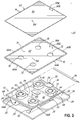
- FIG. 3 is an exploded perspective view of the platen assembly of FIG. 2 .
- FIG. 4 is a cross-sectional view of the platen assembly of FIG. 2 , taken along line 4 - 4 .
- FIG. 5 is a perspective view of a second exemplary embodiment of a platen assembly in accordance with the principles of the present disclosure.
- FIG. 6 is a perspective view of a third exemplary embodiment of a platen assembly, similar to the platen assembly of FIG. 5 .
- FIG. 7 is a perspective view of a fourth exemplary embodiment of a platen assembly in accordance with the principles of the present disclosure.
- FIG. 8 is an exploded perspective view of a fifth exemplary embodiment of a platen assembly in accordance with the principles of the present disclosure.
- FIG. 9 is an exploded perspective view of a sixth exemplary embodiment of a platen assembly in accordance with the principles of the present disclosure.
- FIG. 1 depicts a digital printer system 10 which may be used for direct printing onto substrates such as garments and other textile materials.
- the digital printer system 10 includes an exemplary platen assembly 12 in accordance with the principles of the present disclosure.
- the digital printer system 10 may be configured to apply inks directly to the substrates to create images, text, or other indicia as known in the art.
- the exemplary platen assembly 12 may also be used during the application of pretreatment liquids to substrates, or during the curing of inks and/or pretreatment liquids on the substrates.
- the digital printer system 10 includes a base 14 supporting a housing 16 that contains a printhead assembly or nozzles for applying inks or pretreatment liquids to a substrate.
- the platen assembly 12 with a substrate supported thereon is received on a transport assembly 18 configured to move the platen assembly 12 in a controlled manner beneath the housing 16 for application of the inks and/or pretreatment liquids.
- the platen assembly 12 may remain stationary while printing mechanisms of the printer system 10 are moved over the platen assembly 12 supporting a substrate thereon.
- FIGS. 2-4 the platen assembly 12 is shown in more detail.
- the platen assembly 12 includes a substrate support 20 and a plenum assembly 22 supported on a base 24 by first and second spaced apart legs 26 a , 26 b .
- the first and second legs 26 a , 26 b may include a recessed portion 28 that facilitates receiving certain substrates S, such as T-shirts or sweatshirts onto the platen assembly 12 for printing purposes.
- the base 24 comprises a bottom wall 30 to which the first and second legs 26 a , 26 b are attached by fasteners 32 , for example.
- the base 24 may further include one or more peripheral sidewalls 34 provided along all or a portion of the peripheral edges of the bottom wall 30 .
- the base 24 may be configured to couple with the transport assembly 18 of the printer system 10 whereby the transport assembly 18 may be operated to control movement of the platen assembly 12 relative to the housing 16 .
- the plenum assembly 22 includes a bottom wall 40 and first and second spaced apart sidewalls 42 , 44 provided along opposite lateral edges of the bottom wall 40 .
- An end wall 46 is disposed between the first and second sidewalls 42 , 44 at a first end 48 of the plenum assembly 22 and opposite an open, second end 50 .
- the substrate support 20 is disposed atop the plenum assembly 22 , opposite the bottom wall 40 , and engages the first and second sidewalls 42 , 44 and the end wall 46 of the plenum assembly 22 to define a plenum 52 through which air drawn from the substrate support 20 flows toward the open end 50 as will be described more fully below.
- the substrate support 20 includes a support plate 60 defining a generally planar support surface 62 upon which a substrate S may be received, and a bottom wall 64 spaced from the support plate 60 .
- the substrate support 20 further includes first and second oppositely disposed sidewalls 66 a , 66 b , and first and second oppositely disposed end walls 68 a , 68 b provided along the peripheral edges of the bottom wall 64 and cooperating with the bottom wall 64 to define a vacuum chamber 70 beneath the support plate 60 .
- One or more inlet openings 72 are provided in the bottom wall 64 of the substrate support 20 , through which air is drawn into the plenum 52 to create vacuum pressure within the vacuum chamber 70 and a corresponding flow of air through apertures of the substrate support 20 .
- apertures of the substrate support 20 include a plurality of apertures 74 in the form of circular holes through the support plate 60 .
- the plurality of apertures 74 extend over the entire surface of the support plate 60 .
- apertures 74 in the support plate 60 may have a variety of other configurations.
- apertures 74 through the support plate 60 may have different shapes, such as slots, and may only be provided in selected portions of the support plate as may be desired to facilitate drawing a substrate S tightly against the support plate 60 .
- the substrate support 20 may further include apertures 76 , 78 through one or more of the sidewalls 66 a , 66 b and end walls 68 a , 68 b of the substrate support 20 as depicted in FIGS. 2-4 . Air flowing through these apertures 76 , 78 will cause a substrate S to draw tightly against the surfaces of the sidewalls 66 a , 66 b and/or end walls 68 a , 68 b.
- the platen assembly 12 further includes a vacuum device adapted to create vacuum pressure within the vacuum chamber and thereby cause a corresponding flow of air through the apertures 74 , 76 , 78 in the substrate support 20 .
- the vacuum device comprises a plurality of blowers 80 disposed within the plenum 52 and arranged such that inlets 82 to the blowers 80 are aligned with the inlet openings 72 in the bottom wall 64 of the substrate support 20 . In use, operation of the blowers 80 draws air through the apertures 74 , 76 , 78 in the substrate support 20 into the vacuum chamber 70 , and through the inlet openings 72 to the corresponding inlets 82 of the blowers 80 .
- a deflector plate 86 may be provided at the second end 50 , as depicted in FIGS. 1, 3, and 4 , to direct discharged air from the platen assembly 12 as may be desired. While this embodiment depicts blowers 80 disposed inside the plenum assembly 22 , a vacuum device may alternatively be disposed outside the plenum assembly as may be desired.
- this embodiment depicts vacuum devices in the form of four blowers 80 , it will be appreciated that a different number of blowers may alternatively be used, and that different vacuum devices suitable for creating vacuum pressure within the vacuum chamber 70 and causing a corresponding flow of air through the apertures 74 , 76 , 78 in the substrate support 20 may alternatively be used.
- Power may be provided to the platen assembly 12 from a power source by a wiring harness (not depicted) for operation of the blowers 80 and other components of the platen assembly 12 requiring electrical power.
- the vacuum pressure developed within the vacuum chamber 70 may be selectively adjustable to and between at least a first vacuum pressure and a second vacuum pressure of lower or higher magnitude than the first vacuum pressure.
- the first vacuum pressure may be selected to facilitate securing a substrate S on the substrate support 20 prior to movement of the platen assembly 12 beneath the printer housing 16 to receive inks and/or pretreatment liquid. After the platen assembly 12 is moved to a position proximate the printer housing 16 for receiving inks and/or pretreatment liquid, the vacuum pressure may be switched to the second vacuum pressure.
- the second vacuum pressure may be selected to be a lower level of vacuum that is sufficient to maintain the position of the substrate S on the substrate support 20 , but not so great so that the airflow through the apertures 74 , 76 , 78 caused by the second vacuum pressure interferes with the path of ink or pretreatment liquid droplets in flight between the printhead or nozzles and the substrate S. Nevertheless, because the second vacuum level still creates airflow through porous substrates S such as textile materials, ink and applied pretreatment liquid may be drawn into the porous material of the substrate S. The action of drawing the ink and/or pretreatment liquid into the substrate S provides benefits in terms of increased ink and pretreatment adhesion, as well as improved wash fastness of the finished product.
- appropriate selection of the second vacuum level greatly reduces or eliminates overspray or airborne liquid from being deposited on internal components of the printer system 10 or into surrounding environment, as well as reducing or eliminating the bounce-back of ink or liquid from the substrate S during application. It has been found that proper selection of the second vacuum pressure is able to pull 100 percent of the ink or pretreatment liquid being applied onto the surface of the substrate S.
- the air flow through porous substrates S such as textile materials also provides advantages when the platen assembly 12 is used in processes incorporating heat to dry and/or cure inks and pretreatment liquids applied to the substrates S.
- higher temperatures may be applied to the substrate S without adversely affecting the inks, pretreatment liquids, or the substrate S.
- the platen assembly 12 provides increased control over moisture levels in the printed or treated substrate material. This is particularly advantageous when printing white ink onto substrates S, since airflow through the substrate material forces individual fibers of the substrate S to be fully coated with ink.
- the vacuum pressure which draws the substrate S tightly to the substrate support 20 facilitates securing the substrate S against movement during printing and/or pretreatment, and also ensures that the material of the substrate S does not contract, expand, form wrinkles, or otherwise experience unwanted movement during the printing and/or pretreatment processes.
- the vacuum pressure created by the blowers 80 or other vacuum devices may be controlled between the first and second vacuum pressures, as well as any level of vacuum pressure therebetween. Because different textile fabrics exhibit different degrees of porosity due to variations in consistency, density, weave pattern, and quality, the ability for air to flow through different textile materials also varies.
- the platen assembly 12 allows users to selectively adjust the level of vacuum pressure to correspond to a particular type of textile fabric which is to receive ink or pretreatment liquid, thereby controlling the air flow for optimization of the printing and pretreatment processes.
- the vacuum device such as blowers 80
- the platen assembly 12 may include sensors to detect the presence of a substrate S upon the substrate support 20 and to detect the position of the platen assembly 12 relative to the printer housing 16 to thereby control operation of the vacuum device.
- the platen assembly 12 of the embodiment shown includes one or more sensors for detecting the presence of a substrate S on the substrate support 20 .
- first and second sensors 90 , 92 are supported on a circuit board 94 disposed within the plenum assembly 22 .
- Apertures 96 a , 96 b , 98 a , 98 b may be provided through the bottom wall 64 and support plate 60 of the substrate support 20 , and aligned with the first and second substrate sensors 90 , 92 to facilitate detecting the presence of a substrate S on the substrate support 20 .
- the first and second substrate sensors 90 , 92 are retro-reflective optical sensors, such as Sharp® Digital Optical Sensors, available from Digi-Key Electronics, Thief River Falls, Minn. It will be appreciated, however, the various other sensors may be used that are suitable to detect the presence of a substrate S on the substrate support 20 .
- the platen assembly 12 may further include one or more sensors for sensing the position of the platen assembly 12 relative to the printer housing 16 .
- a position sensor 100 in the form of a magnetic read switch, such as ZF Electronics MP2017 Series Magnetic Reed Switch Sensors, available from Digi-Key Electronics, Thief River Falls, Minn., is disposed within the plenum assembly 22 .
- ZF Electronics MP2017 Series Magnetic Reed Switch Sensors available from Digi-Key Electronics, Thief River Falls, Minn.
- positions sensors may be disposed at various other locations on the platen assembly 12 or the printer system 10 suitable for sensing the position of the platen assembly 12 relative to the printer housing 16 .
- Corresponding apertures 102 , 104 may be provided through the bottom wall 64 and support plate 60 of the substrate support 20 , and aligned with the position sensor 100 to facilitate detecting the position of the platen assembly 12 relative to the printer housing 16 .
- placement of a substrate S on the substrate support 20 is detected by the substrate sensors 90 , 92 , where after the blowers 80 may be controlled to operate at the first, high vacuum pressure to facilitate placement and securing the substrate S on the substrate support 20 .
- the platen assembly 12 When the substrate S is in position, the platen assembly 12 may be moved by the transport assembly 18 toward the printer housing 16 .
- the position sensor 100 detects the relative position of the printer housing 16 .
- the blowers 80 are switched to the second vacuum pressure level where after ink or pretreatment liquid may be applied to the substrate S.
- Operation of the sensors and blowers 80 may be controlled by the circuit board 94 or, alternatively, by a controller associated with the printer system 10 .
- the platen assembly 12 may also be configured such that the substrate sensors 90 , 92 detect the removal of the substrate S after the printing/pretreatment operation. Thereafter, when another substrate S is placed on the platen assembly 12 , detection of the substrate S by the substrate sensors 90 , 92 signals control of the blowers 80 to operate at the first vacuum level, thereby facilitating the placement and securing of the substrate S on the substrate support 20 .
- FIG. 5 depicts another exemplary embodiment of a platen assembly 12 a in accordance with the principles of the present disclosure.
- Platen assembly 12 a of FIG. 5 is similar to the platen assembly 12 described above with respect to FIG. 1-4 , wherein similar features are similarly numbered.
- the platen assembly 12 a further includes a riser 110 disposed above the support plate 60 and adapted to receive substrate materials of a small size or for which printing to a well-defined area is desired.
- the riser 110 includes a riser surface 112 defining a second planar area smaller than the planar area of the support plate 60 .
- the riser surface 112 comprises a generally flat plate supported above the support plate 60 by a plurality of spacers 114 .
- One or more open spaces 116 are thereby defined between the riser surface 112 and the support plate 60 .
- material of the substrate S contacting the support plate 60 is drawn tightly against the support plate 60 by vacuum pressure drawing airflow through the apertures 74 in the support plate 60 while portions of the substrate S adjacent the open spaces around the riser 110 are drawn into the open spaces 116 by airflow through the apertures 74 in the support plate 60 directly beneath the riser 110 .
- This action draws the substrate S tightly against the riser surface 112 to facilitate the application of inks or pretreatment liquids to the substrate S positioned over the riser surface 112 .
- FIG. 6 depicts yet another exemplary embodiment of a platen assembly 12 b similar to the platen assembly 12 a of FIG. 5 and similar features are similarly numbered.
- apertures 74 in the support plate 60 a are only provided in a region of the support plate 60 a that lies directly beneath the riser 110 a , whereby air flow through the openings 116 between the riser 110 a and the support plate 60 a is increased in response to the vacuum pressure in the vacuum chamber 70 .
- Apertures 120 may also be provided in the riser surface 112 a , as may be desired, to increase the draw of the substrate S against the riser 110 a .
- the quantity and arrangement of apertures 74 through the support plate 60 a may be varied by utilizing separate, removable support plates which may be removed and replaced over the vacuum chamber 70 to provide adjustment of the vacuum action acting on the substrate S.
- the quantity and arrangement of apertures 74 through the support plate 60 a may be effectively varied by utilizing templates or masking plates of varying design to close off certain of the apertures 74 through the support plate 60 a , while other apertures 74 remain exposed.
- FIG. 7 depicts another exemplary platen assembly 12 c in accordance with the principles of the present disclosure.
- the platen assembly 12 c of FIG. 7 are similar to the platen assembly 12 of FIGS. 2-4 discussed above and similar features are similarly numbered.
- the platen assembly 12 c further includes a selectively adjustable mechanism for varying the openings of one or more apertures 76 , 78 in the first and second sidewalls 66 a , 66 b and/or first and second end walls 68 a , 68 b of the substrate support 20 a .
- the openings may be varied by the mechanism between a fully open condition, a fully closed condition, and at least one condition intermediate the fully open and fully closed conditions.
- the mechanism for varying the openings of the apertures 76 , 78 comprises one or more plates disposed adjacent the sidewalls 66 a , 66 b or end walls 68 a , 68 b and having corresponding apertures therethrough.
- the plates are slidably adjustable by movement of a lever 130 to various positions along the length of the respective sidewall 66 a , 66 b or end wall 68 a , 68 b to vary the alignment of apertures in the plates with apertures 76 , 78 in the sidewalls 66 a , 66 b or end walls 68 a , 68 b such that the effective openings through the apertures 76 , 78 in the end walls 68 a , 68 b or sidewalls 66 a , 66 b are adjusted.
- the substrate assembly 20 b comprises a support plate 60 and a bottom wall 64 a , similar to substrate assembly 20 of FIGS. 3-4 , and further includes an intermediate plate 140 disposed between the support plate 60 and the bottom wall 64 a .
- the intermediate plate 140 includes oppositely disposed sidewalls 142 a , 142 b and end walls 144 a , 144 b that together with the bottom wall 64 a define the vacuum chamber 70 .
- a plurality of apertures 146 are formed through the intermediate plate 140 to provide fluid communication between the apertures 74 in the support plate 60 and the vacuum chamber 70 .
- the substrate assembly 20 b may further include spacers or stand-offs (not shown) disposed between the support plate 60 and the intermediate plate 140 to control a spacing therebetween, as may be desired, or to control the overall height of the platen assembly 12 d .
- the substrate support 20 b may further include a gasket 148 disposed between the intermediate plate 140 and the bottom wall 64 a , and generally aligned with the sidewalls 142 a , 142 b and end walls 144 a , 144 b to provide a seal therebetween. Operation of the platen assembly 12 d is otherwise similar to operation of the platen assembly 12 described above with respect to FIGS. 1-4 .
- FIG. 9 another exemplary platen assembly 12 e in accordance with the present disclosure is shown and described.
- the platen assembly 12 e is similar to the platen assembly 12 d shown and described above with respect to FIG. 8 , wherein similar features are similarly numbered and differences between the platen assemblies 12 d , 12 e are described herein.
- the apertures 146 in the form of elongate slots are provided on a portion of the intermediate plate 140 a selected to correspond to a substrate S having a size that is generally smaller than the overall size of the top surface of the platen assembly 12 e .
- the support plate 60 b may also have a size that is smaller compared to a support plate 60 that is sized to extend substantially over the entire top surface of the platen assembly 12 e to thereby accommodate smaller sized substrates S or substrates wherein it is desired to print inks or apply pretreatment liquids to a well-defined area.
- the substrate assembly 20 c may further include spacers or stand-offs (not shown) disposed between the support plate 60 b and the intermediate plate 140 a to control a spacing therebetween, as may be desired, or to control the overall height of the platen assembly 12 e .
- the intermediate plate 140 a and/or support plate 60 b may be selectively interchanged with other intermediate plates or support plates of differing configuration to accommodate substrates S of various sizes or configurations.
Landscapes
- Engineering & Computer Science (AREA)
- Textile Engineering (AREA)
- Ink Jet (AREA)
- Treatment Of Fiber Materials (AREA)
- Handling Of Sheets (AREA)
Abstract
Description
Claims (21)
Priority Applications (1)
| Application Number | Priority Date | Filing Date | Title |
|---|---|---|---|
| US16/027,723 US10696065B2 (en) | 2017-07-09 | 2018-07-05 | Platen assembly for textile decorating machines |
Applications Claiming Priority (2)
| Application Number | Priority Date | Filing Date | Title |
|---|---|---|---|
| US201762530278P | 2017-07-09 | 2017-07-09 | |
| US16/027,723 US10696065B2 (en) | 2017-07-09 | 2018-07-05 | Platen assembly for textile decorating machines |
Publications (2)
| Publication Number | Publication Date |
|---|---|
| US20190009575A1 US20190009575A1 (en) | 2019-01-10 |
| US10696065B2 true US10696065B2 (en) | 2020-06-30 |
Family
ID=62904307
Family Applications (1)
| Application Number | Title | Priority Date | Filing Date |
|---|---|---|---|
| US16/027,723 Active US10696065B2 (en) | 2017-07-09 | 2018-07-05 | Platen assembly for textile decorating machines |
Country Status (2)
| Country | Link |
|---|---|
| US (1) | US10696065B2 (en) |
| EP (1) | EP3427963A1 (en) |
Cited By (2)
| Publication number | Priority date | Publication date | Assignee | Title |
|---|---|---|---|---|
| US20220315364A1 (en) * | 2019-12-25 | 2022-10-06 | Brother Kogyo Kabushiki Kaisha | Platen conveyance device |
| US20220324667A1 (en) * | 2019-12-25 | 2022-10-13 | Brother Kogyo Kabushiki Kaisha | Platen conveyance device |
Families Citing this family (4)
| Publication number | Priority date | Publication date | Assignee | Title |
|---|---|---|---|---|
| JP2018138362A (en) * | 2017-02-24 | 2018-09-06 | セイコーエプソン株式会社 | Medium support unit, printing device, and friction member attaching and detaching method |
| US11504980B2 (en) | 2018-12-13 | 2022-11-22 | ColDesi, Inc. | Apparatus and methods for processing digitally printed textile materials |
| US11794483B2 (en) | 2019-08-30 | 2023-10-24 | Primera Technology, Inc. | Delivery tray mounting system for food product printer |
| JP7509034B2 (en) * | 2020-12-28 | 2024-07-02 | ブラザー工業株式会社 | Printer, control method, and control program |
Citations (5)
| Publication number | Priority date | Publication date | Assignee | Title |
|---|---|---|---|---|
| US6068374A (en) * | 1994-02-08 | 2000-05-30 | Canon Kabushiki Kaisha | Image forming apparatus |
| US20070103529A1 (en) * | 2003-06-16 | 2007-05-10 | Kornit Digital Ltd. | Process and system for printing images on absorptive surfaces |
| US8675243B2 (en) * | 2009-02-16 | 2014-03-18 | Vistaprint Schweiz Gmbh | Bleed area adjustment technique for use in printing multiple articles of manufacture |
| US8708480B2 (en) * | 2011-03-15 | 2014-04-29 | Seiko Epson Corporation | Recording apparatus |
| US8714735B2 (en) * | 2011-03-17 | 2014-05-06 | Seiko Epson Corporation | Recording apparatus |
Family Cites Families (4)
| Publication number | Priority date | Publication date | Assignee | Title |
|---|---|---|---|---|
| US4984960A (en) * | 1989-11-29 | 1991-01-15 | Precision Screen Machines, Inc. | Vacuum track and pallets |
| JP2012056242A (en) * | 2010-09-10 | 2012-03-22 | Seiko Epson Corp | Image recording device and image recording method |
| JP6004169B2 (en) * | 2011-09-02 | 2016-10-05 | セイコーエプソン株式会社 | Inkjet printing device |
| US8967792B2 (en) * | 2012-12-07 | 2015-03-03 | Xerox Corporation | Moveable platen cart for handling sheets of substrate media in a printing system |
-
2018
- 2018-07-05 US US16/027,723 patent/US10696065B2/en active Active
- 2018-07-09 EP EP18182357.6A patent/EP3427963A1/en not_active Withdrawn
Patent Citations (5)
| Publication number | Priority date | Publication date | Assignee | Title |
|---|---|---|---|---|
| US6068374A (en) * | 1994-02-08 | 2000-05-30 | Canon Kabushiki Kaisha | Image forming apparatus |
| US20070103529A1 (en) * | 2003-06-16 | 2007-05-10 | Kornit Digital Ltd. | Process and system for printing images on absorptive surfaces |
| US8675243B2 (en) * | 2009-02-16 | 2014-03-18 | Vistaprint Schweiz Gmbh | Bleed area adjustment technique for use in printing multiple articles of manufacture |
| US8708480B2 (en) * | 2011-03-15 | 2014-04-29 | Seiko Epson Corporation | Recording apparatus |
| US8714735B2 (en) * | 2011-03-17 | 2014-05-06 | Seiko Epson Corporation | Recording apparatus |
Cited By (4)
| Publication number | Priority date | Publication date | Assignee | Title |
|---|---|---|---|---|
| US20220315364A1 (en) * | 2019-12-25 | 2022-10-06 | Brother Kogyo Kabushiki Kaisha | Platen conveyance device |
| US20220324667A1 (en) * | 2019-12-25 | 2022-10-13 | Brother Kogyo Kabushiki Kaisha | Platen conveyance device |
| US12024392B2 (en) * | 2019-12-25 | 2024-07-02 | Brother Kogyo Kabushiki Kaisha | Platen conveyance device |
| US12180029B2 (en) * | 2019-12-25 | 2024-12-31 | Brother Kogyo Kabushiki Kaisha | Platen conveyance device |
Also Published As
| Publication number | Publication date |
|---|---|
| EP3427963A1 (en) | 2019-01-16 |
| US20190009575A1 (en) | 2019-01-10 |
Similar Documents
| Publication | Publication Date | Title |
|---|---|---|
| US10696065B2 (en) | Platen assembly for textile decorating machines | |
| US10369815B2 (en) | Inkjet printing device with removable flat substrate support device | |
| US9573393B2 (en) | Movable vacuum divider | |
| EP3392048B1 (en) | Media support system | |
| US11504980B2 (en) | Apparatus and methods for processing digitally printed textile materials | |
| US9403383B1 (en) | Ink and media treatment to affect ink spread on media treated with primer in an inkjet printer | |
| US9527274B2 (en) | Apparatus including a registration system for preparing a screen printing screen | |
| CN109414941B (en) | Vacuum belt for ink jet printing apparatus | |
| CN103502011B (en) | inkjet printing device | |
| US8944588B2 (en) | Pneumatic sheet registration and clamping with vectored air flow | |
| KR20100017230A (en) | Cloth product printing system | |
| JP7155799B2 (en) | Liquid ejector | |
| JP7144870B2 (en) | Sheet material printing system | |
| US9463649B1 (en) | Ink and media treatment to affect ink spread on media in an inkjet printer | |
| JPH07266543A (en) | Guide device for sheet material to be fed in printing press | |
| US20120224003A1 (en) | Sheet processing device | |
| CN108290422B (en) | Inkjet printing device for rigid multilayer substrates, inkjet printing method and use | |
| US11142012B2 (en) | Removable dryer module for a printing apparatus | |
| CN206953780U (en) | Textile printing machine | |
| CN109383132A (en) | Equipment for being printed and being dried to printable fabric | |
| JP2014140989A (en) | Recording device | |
| GB2518148A (en) | Printing system | |
| US11760086B2 (en) | System and method for printing color images on substrates in an inkjet printer | |
| US9290018B1 (en) | Vacuum pulldown of print media in printer | |
| KR20080108978A (en) | Drying System for Image Former |
Legal Events
| Date | Code | Title | Description |
|---|---|---|---|
| FEPP | Fee payment procedure |
Free format text: ENTITY STATUS SET TO UNDISCOUNTED (ORIGINAL EVENT CODE: BIG.); ENTITY STATUS OF PATENT OWNER: SMALL ENTITY |
|
| AS | Assignment |
Owner name: COLDESI INC., FLORIDA Free format text: ASSIGNMENT OF ASSIGNORS INTEREST;ASSIGNORS:MOMBOURQUETTE, MARK;WEIBEL, BRETT;REEL/FRAME:046372/0560 Effective date: 20180716 |
|
| FEPP | Fee payment procedure |
Free format text: ENTITY STATUS SET TO SMALL (ORIGINAL EVENT CODE: SMAL); ENTITY STATUS OF PATENT OWNER: SMALL ENTITY |
|
| STPP | Information on status: patent application and granting procedure in general |
Free format text: DOCKETED NEW CASE - READY FOR EXAMINATION |
|
| STPP | Information on status: patent application and granting procedure in general |
Free format text: NON FINAL ACTION MAILED |
|
| STPP | Information on status: patent application and granting procedure in general |
Free format text: RESPONSE TO NON-FINAL OFFICE ACTION ENTERED AND FORWARDED TO EXAMINER |
|
| STPP | Information on status: patent application and granting procedure in general |
Free format text: FINAL REJECTION MAILED |
|
| STCF | Information on status: patent grant |
Free format text: PATENTED CASE |
|
| MAFP | Maintenance fee payment |
Free format text: PAYMENT OF MAINTENANCE FEE, 4TH YR, SMALL ENTITY (ORIGINAL EVENT CODE: M2551); ENTITY STATUS OF PATENT OWNER: SMALL ENTITY Year of fee payment: 4 |