JP2012056242A - Image recording device and image recording method - Google Patents
Image recording device and image recording method Download PDFInfo
- Publication number
- JP2012056242A JP2012056242A JP2010203215A JP2010203215A JP2012056242A JP 2012056242 A JP2012056242 A JP 2012056242A JP 2010203215 A JP2010203215 A JP 2010203215A JP 2010203215 A JP2010203215 A JP 2010203215A JP 2012056242 A JP2012056242 A JP 2012056242A
- Authority
- JP
- Japan
- Prior art keywords
- negative pressure
- suction
- pressure chamber
- medium
- mode
- Prior art date
- Legal status (The legal status is an assumption and is not a legal conclusion. Google has not performed a legal analysis and makes no representation as to the accuracy of the status listed.)
- Pending
Links
Images


Classifications
-
- B—PERFORMING OPERATIONS; TRANSPORTING
- B41—PRINTING; LINING MACHINES; TYPEWRITERS; STAMPS
- B41J—TYPEWRITERS; SELECTIVE PRINTING MECHANISMS, i.e. MECHANISMS PRINTING OTHERWISE THAN FROM A FORME; CORRECTION OF TYPOGRAPHICAL ERRORS
- B41J11/00—Devices or arrangements of selective printing mechanisms, e.g. ink-jet printers or thermal printers, for supporting or handling copy material in sheet or web form
- B41J11/0085—Using suction for maintaining printing material flat
-
- B—PERFORMING OPERATIONS; TRANSPORTING
- B41—PRINTING; LINING MACHINES; TYPEWRITERS; STAMPS
- B41J—TYPEWRITERS; SELECTIVE PRINTING MECHANISMS, i.e. MECHANISMS PRINTING OTHERWISE THAN FROM A FORME; CORRECTION OF TYPOGRAPHICAL ERRORS
- B41J11/00—Devices or arrangements of selective printing mechanisms, e.g. ink-jet printers or thermal printers, for supporting or handling copy material in sheet or web form
- B41J11/02—Platens
- B41J11/06—Flat page-size platens or smaller flat platens having a greater size than line-size platens
Abstract
Description
本発明は、画像記録装置、及び、画像記録方法に関する。 The present invention relates to an image recording apparatus and an image recording method.
画像記録装置の一例であるインクジェットプリンター等には、画像を印刷する媒体が、インクを吐出するヘッドに対して一定の姿勢となるように、媒体を支持するプラテン(媒体支持部)が設けられている。(例えば、特許文献1)。 An inkjet printer or the like, which is an example of an image recording apparatus, is provided with a platen (medium support unit) that supports a medium so that a medium on which an image is printed is in a fixed posture with respect to a head that ejects ink. Yes. (For example, patent document 1).
例えば、印刷時にはプラテン上の媒体が一定の位置に保持されるように、プラテンに吸引孔を設け、吸引孔から媒体を吸引するプリンターがある。しかし、媒体搬送時に媒体に対する吸引力が強いと搬送の妨げとなる。そこで、媒体搬送時には媒体に対する吸引力を低下させるとよい。ただし、媒体に対する吸引力を低下させるのに時間がかかると、全体の印刷作業時間が長くなってしまう。 For example, there is a printer in which a suction hole is provided in the platen so that the medium on the platen is held at a certain position during printing, and the medium is sucked from the suction hole. However, if the suction force with respect to the medium is strong when the medium is transported, the transport is hindered. Therefore, it is preferable to reduce the suction force to the medium when the medium is transported. However, if it takes time to reduce the suction force on the medium, the entire printing operation time becomes long.
本発明は、このような事情に鑑みてなされたものであり、その目的とするところは、媒体に対する吸引力低下に要する時間を出来る限り短縮することにある。 The present invention has been made in view of such circumstances, and an object of the present invention is to shorten the time required for reducing the suction force to the medium as much as possible.
上記課題を解決するための主たる発明は、(A)媒体に画像を記録する記録部と、(B)前記媒体を搬送する搬送部と、(C)吸引孔の開口部が設けられた支持面で前記媒体を支持する媒体支持部と、(D)前記吸引孔を介して前記媒体支持部に支持された前記媒体を吸引する吸引部であって、前記吸引孔と連通する負圧室と、前記負圧室の内部の空気を吐き出して前記負圧室内に負圧を発生させる少なくとも2つの送風部と、を有し、前記負圧室の外面の異なる位置に前記少なくとも2つの送風部が取り付けられた吸引部と、(E)前記媒体に対する前記吸引部の吸引力を第1の吸引力とする第1のモードと、前記吸引力を前記第1の吸引力よりも低い第2の吸引力とする第2のモードと、を切り替える制御部であって、前記第2のモード時には、前記少なくとも2つの送風部のうちの1つの送風部を停止する制御部と、(F)を備えたことを特徴とする画像記録装置である。
本発明の他の特徴については、本明細書及び添付図面の記載により明らかにする。
The main invention for solving the above problems is (A) a recording unit that records an image on a medium, (B) a conveyance unit that conveys the medium, and (C) a support surface provided with an opening of a suction hole. And (D) a suction part for sucking the medium supported by the medium support part through the suction hole, and a negative pressure chamber communicating with the suction hole, And at least two air blowing sections that discharge air inside the negative pressure chamber to generate a negative pressure in the negative pressure chamber, and the at least two air blowing sections are attached to different positions on the outer surface of the negative pressure chamber And (E) a first mode in which the suction force of the suction portion with respect to the medium is a first suction force, and a second suction force that is lower than the first suction force. And a second mode for switching between the second mode and the second mode. The a control section for stopping one blower of the at least two blower, an image recording apparatus comprising the (F).
Other features of the present invention will become apparent from the description of the present specification and the accompanying drawings.
本明細書及び添付図面の記載により、少なくとも以下の事項が明らかとなる。 At least the following matters will become apparent from the description of the present specification and the accompanying drawings.
即ち、(A)媒体に画像を記録する記録部と、(B)前記媒体を搬送する搬送部と、(C)吸引孔の開口部が設けられた支持面で前記媒体を支持する媒体支持部と、(D)前記吸引孔を介して前記媒体支持部に支持された前記媒体を吸引する吸引部であって、前記吸引孔と連通する負圧室と、前記負圧室の内部の空気を吐き出して前記負圧室内に負圧を発生させる少なくとも2つの送風部と、を有し、前記負圧室の外面の異なる位置に前記少なくとも2つの送風部が取り付けられた吸引部と、(E)前記媒体に対する前記吸引部の吸引力を第1の吸引力とする第1のモードと、前記吸引力を前記第1の吸引力よりも低い第2の吸引力とする第2のモードと、を切り替える制御部であって、前記第2のモード時には、前記少なくとも2つの送風部のうちの1つの送風部を停止する制御部と、(F)を備えたことを特徴とする画像記録装置である。
このような画像記録装置によれば、第1のモードから第2のモードへの切り替え時間(吸引力低下に要する時間)を短縮することができる。
That is, (A) a recording unit that records an image on a medium, (B) a conveyance unit that conveys the medium, and (C) a medium support unit that supports the medium on a support surface provided with an opening of a suction hole. And (D) a suction part for sucking the medium supported by the medium support part through the suction hole, and a negative pressure chamber communicating with the suction hole, and air inside the negative pressure chamber. (E) a suction part having at least two air blowing units that discharge and generate negative pressure in the negative pressure chamber, and the at least two air blowing parts are attached to different positions on the outer surface of the negative pressure chamber; A first mode in which the suction force of the suction unit with respect to the medium is a first suction force; and a second mode in which the suction force is a second suction force lower than the first suction force. A control unit for switching, wherein the at least two blowers are in the second mode; A control unit for stopping one blower of an image recording apparatus comprising the (F).
According to such an image recording apparatus, it is possible to shorten the time for switching from the first mode to the second mode (the time required for reducing the suction force).
かかる画像記録装置であって、前記少なくとも2つの送風部のうちの一の送風部の吸込口と連通する前記負圧室の開口部を通過する風量の方が、他の送風部の吸込口と連通する前記負圧室の開口部を通過する風量よりも大きいこと。
このような画像記録装置によれば、負圧室内に発生させられる負圧の範囲を広くすることができる。その結果、媒体に対する吸引力をより強くでき、また、より弱くできる。
In such an image recording apparatus, the amount of air passing through the opening of the negative pressure chamber communicating with the suction port of one of the at least two blowers is larger than the suction port of the other blower. It must be larger than the amount of air passing through the opening of the negative pressure chamber that communicates.
According to such an image recording apparatus, the range of the negative pressure generated in the negative pressure chamber can be widened. As a result, the suction force for the medium can be made stronger and weaker.
かかる画像記録装置であって、前記制御部は、前記第2のモード時には、前記一の送風部を停止すること。
このような画像記録装置によれば、第2のモード時に、負圧室内の負圧をより低くすることができる。その結果、媒体に対する吸引力をより弱くする事ができる。
In this image recording apparatus, the control unit stops the one air blowing unit in the second mode.
According to such an image recording apparatus, the negative pressure in the negative pressure chamber can be further reduced in the second mode. As a result, the suction force with respect to the medium can be further reduced.
かかる画像記録装置であって、前記一の送風部では、少なくとも2つの送風機が直列に取り付けられていること。
このような画像記録装置によれば、一の送風部の吸込口と連通する負圧室の開口部を通過する風量を大きくすることができる。
In such an image recording apparatus, at least two blowers are attached in series in the one blower unit.
According to such an image recording apparatus, it is possible to increase the amount of air passing through the opening of the negative pressure chamber communicating with the suction port of the one air blowing unit.
かかる画像記録装置であって、前記制御部は、前記記録部による前記媒体への画像の記録動作中に、前記第1のモードから前記第2のモードに切り替えること。
このような画像記録装置によれば、全体の記録作業時間を短縮することができる。
In this image recording apparatus, the control unit switches from the first mode to the second mode during an image recording operation on the medium by the recording unit.
According to such an image recording apparatus, the entire recording work time can be shortened.
かかる画像記録装置であって、前記少なくとも2つの送風部は前記媒体支持部に直接的又は間接的に取り付けられていること。
このような画像記録装置によれば、第2のモード時には1つの送風部を停止するため、例えば、媒体支持部が載置される基台に伝わる振動を抑制することができ、吐出不良検査の精度を上げることができる。
In this image recording apparatus, the at least two air blowing sections are directly or indirectly attached to the medium support section.
According to such an image recording apparatus, since one air blowing unit is stopped in the second mode, for example, vibration transmitted to the base on which the medium support unit is placed can be suppressed, and an ejection failure inspection can be performed. The accuracy can be increased.
また、(A)媒体に画像を記録する記録部と、(B)前記媒体を搬送する搬送部と、(C)吸引孔の開口部が設けられた支持面で前記媒体を支持する媒体支持部と、(D)前記吸引孔を介して前記媒体支持部に支持された前記媒体を吸引する吸引部であって、前記吸引孔と連通する負圧室と、前記負圧室の内部の空気を吐き出して前記負圧室内に負圧を発生させる少なくとも2つの送風部と、を有し、前記負圧室の外面の異なる位置に前記少なくとも2つの送風部が取り付けられた吸引部と、(E)前記媒体に対する前記吸引部の吸引力を第1の吸引力とする第1のモードと、前記吸引力を前記第1の吸引力よりも低い第2の吸引力とする第2のモードと、を切り替える制御部であって、前記第2のモード時には、前記少なくとも2つの送風部のうちの1つの送風部を停止する制御部と、(F)を備えた画像記録装置を用いて前記媒体に画像を記録することを特徴とする画像記録方法である。
このような画像記録方法によれば、第1のモードから第2のモードへの切り替え時間(吸引力低下に要する時間)を短縮することができる。
(A) a recording unit that records an image on a medium; (B) a transport unit that transports the medium; and (C) a medium support unit that supports the medium on a support surface provided with an opening of a suction hole. And (D) a suction part for sucking the medium supported by the medium support part through the suction hole, and a negative pressure chamber communicating with the suction hole, and air inside the negative pressure chamber. (E) a suction part having at least two air blowing units that discharge and generate negative pressure in the negative pressure chamber, and the at least two air blowing parts are attached to different positions on the outer surface of the negative pressure chamber; A first mode in which the suction force of the suction unit with respect to the medium is a first suction force; and a second mode in which the suction force is a second suction force lower than the first suction force. A control unit for switching, wherein the at least two blowers are in the second mode; A control unit for stopping one blower of an image recording method, which comprises recording an image on the medium using an image recording apparatus equipped with (F).
According to such an image recording method, the switching time from the first mode to the second mode (time required for reducing the suction force) can be shortened.
===プリンターについて===
以下、「画像記録装置」としてインクジェットプリンター(以下、プリンター)を例に挙げて実施形態を説明する。
=== About the printer ===
Hereinafter, an embodiment will be described by taking an inkjet printer (hereinafter, a printer) as an example of the “image recording apparatus”.
図1は、プリンター1の全体構成ブロック図である。図2は、プリンター1の概略を示す断面図である。本実施形態のプリンター1は、媒体として、ロール紙R(連続紙)に画像を印刷する。媒体は、紙に限らず、例えばフィルムや布地でもよい。また、本実施形態のプリンター1はコンピューター2と通信可能に接続されており、コンピューター2が、プリンター1に画像を印刷させるための印刷データを作成する。なお、コンピューター2の機能がプリンター1内に内蔵されていてもよい。 FIG. 1 is a block diagram of the overall configuration of the printer 1. FIG. 2 is a cross-sectional view illustrating an outline of the printer 1. The printer 1 of the present embodiment prints an image on roll paper R (continuous paper) as a medium. The medium is not limited to paper, and may be a film or fabric, for example. Further, the printer 1 of the present embodiment is connected to the computer 2 so as to be communicable, and the computer 2 creates print data for causing the printer 1 to print an image. The function of the computer 2 may be built in the printer 1.
コントローラー10は、プリンター1の制御を行うための制御ユニットである。インターフェース部11はコンピューター2とプリンター1との間でデータの送受信を行うためのものである。CPU12はプリンター1全体の制御を行うための演算処理装置である。メモリー13はCPU12のプログラムを格納する領域や作業領域等を確保するためのものである。CPU12はユニット制御回路14に従って各ユニットを制御する。なお、プリンター1内の状況を検出器群50が監視し、その検出結果に基づいて、コントローラー10は各ユニットを制御する。
The
搬送ユニット20(搬送部に相当)は、予め設定された搬送経路に沿ってロール紙Rを搬送方向の上流側から下流側に搬送するものであり、ロール紙Rの一部を印刷領域に搬送するものである。搬送ユニット20は、供給ローラー21a,21b、排出ローラー22a,22b、巻取りローラー23等を有する。供給ローラー21a,21b及び排出ローラー22a,22bはそれぞれ対を成すローラーから構成され、一方のローラーは不図示のモーターにより回転する駆動ローラーであり、他方のローラーは駆動ローラーに連動して回転する従動ローラーである。印刷領域に位置するロール紙Rに対する画像の印刷が終了すると、供給ローラー21a,21bや排出ローラー22a,22b等によって、画像が印刷されたロール紙Rの部位は印刷領域から排出されて巻き取りローラー23によってロール状に巻き取られ、未だ画像が印刷されていないロール紙Rの部位が印刷領域に供給される。
The transport unit 20 (corresponding to a transport unit) transports the roll paper R from the upstream side to the downstream side in the transport direction along a preset transport path, and transports a part of the roll paper R to the printing area. To do. The
記録ユニット30(記録部に相当)は、印刷領域に位置するロール紙Rに画像を印刷(記録)するものである。印刷領域に位置するロール紙Rは印刷面とは反対側の裏面側からプラテン31(媒体支持部に相当)の上面により支持される。記録ユニット30は、キャリッジ32、ヘッド33等を有する。キャリッジ32は、ガイド軸(不図示)に案内されながら、ヘッド33をX方向(ロール紙Rの搬送方向)及びY方向(ロール紙Rの幅方向)に移動させる。ヘッド33はロール紙Rにインクを吐出するためのものであり、ヘッド33の下面にはインク吐出部であるノズルNzが複数設けられている。なお、ノズルからのインク吐出方式は、駆動素子(ピエゾ素子)に電圧をかけて圧力室を膨張・収縮させてインクを吐出させるピエゾ方式でもよいし、発熱素子を用いてノズル内に気泡を発生させ、その気泡によってインクを吐出させるサーマル方式でもよい。
The recording unit 30 (corresponding to a recording unit) prints (records) an image on the roll paper R located in the printing area. The roll paper R positioned in the printing area is supported by the upper surface of the platen 31 (corresponding to the medium support portion) from the back side opposite to the printing surface. The
プラテン31内部には複数のヒーター311(例えばニクロム線)が配設されている。ヒーター311が通電されることによりプラテン31の温度が上昇し、プラテン31上のロール紙R(即ち、印刷領域に位置するロール紙R)の温度も上昇する。その結果、プラテン31上のロール紙Rに着弾したインクの乾燥を促進することができ、印刷画像におけるインクの滲みを抑制できる。プラテン31上のロール紙Rに対して熱が均一に伝導するように、プラテン31の全域に亘ってヒーター311が配設されている。
A plurality of heaters 311 (for example, nichrome wire) are disposed inside the
また、プリンター1の筐体の天井部1aには、複数の天井ファン34がプラテン31と対向するように設けられている。天井ファン34からプラテン31上のロール紙Rに向けて風が送られることにより、プラテン31上のロール紙Rに着弾したインクの乾燥を促進することができる。
A plurality of
また、キャリッジ32及びヘッド33は、印刷領域よりも搬送方向上流側のホームポジションに退避可能である。ホームポジションにはキャップ機構35等が設けられている。印刷停止中、ヘッド33のノズル面をキャップ機構35により密閉することで、ノズルからのインク蒸発を抑制することが出来る。
Further, the
また、プリンター1の筐体内には平板状の基台1bが設けられており、筐体内は2つの空間に区画される。基台1bよりも上側の空間においてロール紙Rに対する画像の印刷が行われる。よって、ヘッド33及びキャリッジ32は基台1bよりも上側の空間に配置され、基台1b上に、プラテン31、負圧室41、キャップ機構35等が載置されている。
A
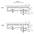
吸引ユニット40(吸引部に相当)は、プラテン31上のロール紙Rをプラテン31の支持面に吸引吸着させるためのものであり、負圧室41、第1ファン機構42、第2ファン機構43、吸引孔44等を有する。プラテン31の底面には負圧室41が接続され、負圧室41の底面には第1ファン機構42と第2ファン機構43とが搬送方向に並んで取り付けられている。なお、第2ファン機構43は2つのファン43a,43bから構成され、一方のファン43aの下側(吐出口側)に他方のファン43bが取り付けられている。また、プラテン31には上下方向に貫通する孔である吸引孔44が形成され、吸引孔44の一方の開口部はプラテン31の支持面に設けられ、吸引孔44の他方の開口部はプラテン31の底面(プラテン31と負圧室41の接続面)に設けられている。即ち、負圧室41は吸引孔44を介して外部(プラテン31の上部)と連通している。また、プラテン31は吸引孔44の開口部が設けられた支持面でロール紙Rを支持することになる。
The suction unit 40 (corresponding to a suction unit) is for sucking and adsorbing the roll paper R on the
第1ファン機構42及び第2ファン機構43は、負圧室41の内部の空気を外部に吐き出し(即ち、負圧室41の内部の空気を吸引し)、負圧室41の内部を負圧状態にする。その際に、プラテン31の支持面上の外気が吸引孔44を介して負圧室41の内部に吸引され、プラテン31上のロール紙Rはプラテン31の支持面に吸引吸着する。即ち、吸引ユニット40は吸引孔44を介してプラテン31に支持されたロール紙Rを2つのファン機構42,43によって吸引する。
The
印刷中に、プラテン31上のロール紙Rをプラテン31の支持面に吸引吸着させることで、プラテン31の支持面においてロール紙Rが所定の位置に保持されて、インク滴を正しい位置に着弾させることができる。また、インク滴の水分でロール紙Rが膨潤したとしてもロール紙Rを平坦な状態に保持することができる。
During printing, the roll paper R on the
このような構成のプリンター1において、コントローラー10が、ヘッド33をキャリッジ32と共にX方向及びY方向に移動させながら印刷領域に位置するロール紙Rに2次元の画像を印刷させる(記録動作に相当)。その後、コントローラー10は、搬送ユニット20に、画像が印刷されたロール紙Rの部位を印刷領域外に排出させ、未だ画像が印刷されていないロール紙Rの部位を印刷領域に供給させる(搬送動作に相当)。つまり、コントローラー10(制御部に相当)は、画像の印刷動作とロール紙Rの搬送動作を繰り返し実行させることによって、ロール紙Rの連続する方向に沿って多数の画像を印刷させる。
In the printer 1 having such a configuration, the
===メンテナンス動作について===
インク内の水分はノズルのメニスカス(外部に露出しているインクの自由表面)から蒸発しやすく、蒸発によりインクの粘度は上昇してしまう。インクが増粘すると、ノズルからインクが吐出されるべき時に規定量のインクが吐出されずに吐出不良が発生する。また、ノズルのメニスカスから大気が混入したり、ノズルに異物が付着したりすることによっても、吐出不良が発生する。ノズルに吐出不良が発生すると、印刷画像の画質が劣化してしまう。
=== About maintenance operation ===
The water in the ink easily evaporates from the meniscus of the nozzle (the free surface of the ink exposed to the outside), and the viscosity of the ink increases due to the evaporation. When the ink is thickened, when the ink is to be ejected from the nozzle, a specified amount of ink is not ejected, resulting in ejection failure. In addition, ejection failure also occurs when air is mixed in from the meniscus of the nozzle or foreign matter adheres to the nozzle. When ejection failure occurs in the nozzle, the image quality of the printed image deteriorates.
そこで、本実施形態のプリンター1では、定期的にメンテナンス動作を実施する。「メンテナンス動作」とは、吐出不良が発生するノズル(不良ノズル)の有無を検出する「吐出不良検査」や、不良ノズルから正常にインクが吐出されるようにする「クリーニング動作」の事である。なお、メンテナンス動作では、例えば、吐出不良検査が実行された後に不良ノズルが検出された場合にだけクリーニング動作が実行されるようにしても良いし、不良ノズルが検出されなくなるまでクリーニング動作と吐出不良検査が繰り返し実行されるようにしても良い。 Therefore, the printer 1 of the present embodiment periodically performs a maintenance operation. “Maintenance operation” means “discharge failure inspection” for detecting the presence or absence of a nozzle (defective nozzle) that causes a discharge failure, and “cleaning operation” for properly discharging ink from the defective nozzle. . In the maintenance operation, for example, the cleaning operation may be performed only when a defective nozzle is detected after the discharge defect inspection is performed, or until the defective nozzle is no longer detected. The inspection may be repeatedly executed.
<吐出不良検査>
本実施形態の吐出不良検査ユニット(不図示)は、高電位の検出用電極、インク回収部等を有し、インク回収部内に検出用電極が載置されている。吐出不良検査ユニットは、図2のキャップ機構35と同様に、ホームポジションにおいて、プリンター1の基台1bに載置されている。ヘッド33のノズル面(ノズルプレート・導電性を有する板状の部材)は、グランドに接続され、検出用電極よりも低い電位(グランド電位)となっており、また、インクの溶媒は導電性を有する液体(例えば水)とする。よって、ノズルから吐出されるインクはグランド電位となる。
<Discharge defect inspection>
The ejection failure inspection unit (not shown) of this embodiment has a high-potential detection electrode, an ink recovery unit, and the like, and the detection electrode is placed in the ink recovery unit. The ejection failure inspection unit is placed on the
吐出不良検査時、まず、ヘッド33をホームポジションに退避させる。そして、ヘッド33(ノズルプレート)と検出用電極を、所定の間隔を空けた状態で対向させて、検査対象のノズルから(連続的に)インクを吐出させる。そして、インクの吐出に起因して検出用電極側に生じる電気的な変化(電位変化)に基づいて、検出対象のノズルからインク滴が正常に吐出されたか否かを判断する。例えば、検出用電極に生じた電気的な変化を電圧信号として取得し、電圧信号の最大振幅が閾値よりも大きければノズルから正常にインクが吐出されたと判断し、電圧信号の最大振幅が閾値以下であればノズルから正常にインクが吐出されなかったと判断する。なお、ノズルから検出用電極に向けて吐出されたインクはインク回収部が回収するため、プリンター1内の汚れを防止することができる。また、吐出不良検査の方法は、これに限らず、他の方法であっても良い。
At the time of ejection failure inspection, first, the
<クリーニング動作>
本実施形態では、クリーニング動作として、フラッシング、ポンプ吸引、ワイピング等を実施する。クリーニング動作時も、吐出不良検査時と同様に、ヘッド33をホームポジションに退避させる。
「フラッシング」とは、ヘッド33とインク回収部(不図示)を対向させた状態で、強制的にノズルからインクを吐出させ、増粘したインクやノズル面に付着した異物をインクとともに吐出させる動作である。
「ポンプ吸引」とは、ヘッド33のノズル面とインク回収部を密着させて、インク回収部の底面に接続されたチューブを介してポンプ吸引することで(不図示)、ヘッド33内のインクを増粘したインクや異物とともに吸引する動作である。
「ワイピング」とは、ゴム製のワイパー等でノズル面を擦って異物などを除去する動作である。
<Cleaning operation>
In the present embodiment, flushing, pump suction, wiping, and the like are performed as the cleaning operation. During the cleaning operation, the
“Flushing” is an operation in which ink is forcibly ejected from a nozzle in a state where the
“Pump suction” means that the nozzle surface of the
“Wiping” is an operation of removing foreign matters by rubbing the nozzle surface with a rubber wiper or the like.
===高吸引モード・低吸引モード===
図3Aは、高吸引モードを説明する図であり、図3Bは、低吸引モードを説明する図である。前述のように、本実施形態のプリンター1は、吸引孔44を介してプラテン31に支持されたロール紙Rを吸引する吸引ユニット40であり、吸引孔44と連通する負圧室41と、負圧室41の内部の空気を吐き出して負圧室41内に負圧を発生させる第1ファン機構42及び第2ファン機構43とを備えた吸引ユニット40を有する。なお、負圧室41の上面41cにも多数の孔が設けられ、負圧室41の上面41cに設けられた孔とプラテン31に設けられた吸引孔44とが連通している。また、ここでは、「第1ファン機構42及び第2ファン機構43」が「2つの送風部」に相当し、「送風機」として「(軸流)ファン」を例に挙げて説明する。
=== High suction mode / Low suction mode ===
FIG. 3A is a diagram illustrating the high suction mode, and FIG. 3B is a diagram illustrating the low suction mode. As described above, the printer 1 according to the present embodiment is the
ロール紙Rへの画像の印刷動作中は、プラテン31上のロール紙Rを所定の位置に保持し、且つ、インクの水分でロール紙Rが膨潤したとしてもロール紙Rを平坦な状態に保持するために、プラテン31の支持面におけるロール紙Rの吸引吸着力を出来る限り強くしたい。印刷動作中に、ロール紙Rをプラテン31の支持面にしっかりと吸引吸着させて平坦な状態に保持することで、プラテン31(ヒーター311)の熱がプラテン31上のロール紙Rに伝わり、インクの乾燥を促進することができ、画像の滲みを防止することができる。その他、ロール紙Rの正しい位置にインク滴を着弾させることができたり、ロール紙Rとヘッド33の接触を防止することができたりする。即ち、印刷動作中は、プラテン31上のロール紙Rを所定の位置に平坦な状態で保持することで、印刷画像の画質劣化を抑制できる。
During the printing operation of the image on the roll paper R, the roll paper R on the
一方、ロール紙Rの搬送動作中は、搬送に対する大きな抵抗とならないように、プラテン31の支持面におけるロール紙Rの吸引吸着力を、ロール紙Rが弛まない程度に、出来る限り弱くしたい。
On the other hand, during the conveyance operation of the roll paper R, it is desired to reduce the suction suction force of the roll paper R on the support surface of the
つまり、搬送動作中は印刷動作中に比べて、プラテン31上のロール紙Rに対する吸引ユニット40の吸引力を低くしたい。このように、処理動作に応じて、プラテン31上のロール紙Rに対する適切な吸引力が異なる。
That is, the suction force of the
そこで、本実施形態のプリンター1では、ロール紙Rに対する吸引ユニット40の吸引力を高い吸引力(第1の吸引力に相当)とする「高吸引モード(第1のモードに相当)」と、ロール紙Rに対する吸引ユニット40の吸引力を高吸引モードにおける吸引力よりも低い吸引力(第2の吸引力に相当)とする「低吸引モード(第2のモードに相当)」とを、コントローラー10によって切り替え可能とする。
Therefore, in the printer 1 of the present embodiment, “high suction mode (corresponding to the first mode)” in which the suction force of the
そして、コントローラー10は、印刷動作中は高吸引モードに設定し、ロール紙Rの搬送中は低吸引モードに設定する。そうすることで、印刷動作中は、プラテン31上のロール紙Rを所定の位置に平坦な状態で保持することができ、印刷画像の画質劣化を防止できる。一方、ロール紙Rの搬送動作中は、プラテン31の支持面におけるロール紙Rの吸引吸着力を弱くすることができ、スムーズに搬送が行われる。逆に言えば、ロール紙Rの搬送中に低吸引モードに設定することで、搬送ユニット20の駆動力(例えば、排出ローラー22a,22bの引っ張り力)を低減することが出来る。
Then, the
プラテン31上のロール紙Rに対する吸引力を変更するためには、負圧室41内の負圧を変えればよい。負圧室41内の負圧を高くすることで(圧力を下げることで)、プラテン31上のロール紙Rに対する吸引力を高めることができ、負圧室41内の負圧を低くすることで(圧力を上げることで)、プラテン31上のロール紙Rに対する吸引力を低くすることができる。即ち、本実施形態のプリンター1は、負圧室41内の負圧を高い負圧にするモードと、負圧室41内の負圧を低い負圧にするモードとを、切り替え可能なプリンターであるとも言える。
In order to change the suction force for the roll paper R on the
ただし、印刷動作の終了後に、高吸引モードから低吸引モードに切り替えて、その後に、ロール紙Rの搬送動作を実行する場合、高吸引モードから低吸引モードへの切り替え時間が長いと、全体の印刷作業時間が長くなってしまう。また、全体の印刷作業時間を短縮するために、印刷動作中に、高吸引モードから低吸引モードに切り替える場合、高吸引モードから低吸引モードへの切り替え時間が長いと、印刷動作中に高吸引モードでないが時間が長くなってしまう。 However, after the printing operation is finished, when switching from the high suction mode to the low suction mode and then performing the transport operation of the roll paper R, if the switching time from the high suction mode to the low suction mode is long, The printing work time becomes longer. In addition, when switching from the high suction mode to the low suction mode during the printing operation in order to shorten the overall printing work time, if the switching time from the high suction mode to the low suction mode is long, the high suction is performed during the printing operation. It's not a mode, but it takes a long time.
ゆえに、本実施形態では、高吸引モードから低吸引モードへの切り替え時間(即ち、ロール紙Rに対する吸引力低下に要する時間)を、出来る限り短縮することを目的とする。 Therefore, an object of the present embodiment is to shorten the switching time from the high suction mode to the low suction mode (that is, the time required for reducing the suction force with respect to the roll paper R) as much as possible.
そこで、本実施形態のプリンター1では、負圧室41の底面41aの異なる位置に第1ファン機構42と第2ファン機構43を取り付ける(2つのファン機構42,43の軸を同一軸上に位置させずに、2つのファン機構42,43を並列に取り付ける)。そして、コントローラー10は、低吸引モード時には、2つのファン機構42,43のうちの1つのファン機構を停止する。
Therefore, in the printer 1 of the present embodiment, the
具体的には、高吸引モード時には、図3Aに示すように、第1ファン機構42と第2ファン機構43の両方をオン状態にする。この場合、2つのファン機構42,43によって、負圧室41内の空気が外部に吐き出される。一方、低吸引モード時には、図3Bに示すように、第1ファン機構42をオン状態にし、第2ファン機構43をオフ状態にする(停止する)。この場合、第1ファン機構42によって負圧室41内の空気が外部に吐き出されつつ、第2ファン機構43によって負圧室41内が大気開放される。そのため、第2ファン機構43から外部の空気が負圧室41内に吸入される。詳しく言えば、第2ファン機構43の吸込口と連通する負圧室41の開口部41eを通過して、外部の空気が負圧室41内に吸入される。その結果、負圧室41内の負圧は直ぐに低下し(圧力が上がり)、高吸引モードから低吸引モードへの切り替えを速やかに行うことができる。
Specifically, in the high suction mode, as shown in FIG. 3A, both the
つまり、本実施形態のプリンター1によれば(又は、本実施形態のプリンター1を用いた印刷方法によれば)、低吸引モード時には第2ファン機構43を停止して、第2ファン機構43(厳密には、第2ファン機構43の吸込口と連通する負圧室41の開口部41e)を「空気孔」として利用するため、高吸引モードから低吸引モードへの切り替え時間を短縮することができる。
That is, according to the printer 1 of the present embodiment (or according to the printing method using the printer 1 of the present embodiment), the
その結果、例えば、印刷動作の後に高吸引モードから低吸引モードに切り替える場合には、全体の印刷作業時間を短縮することができる。一方、印刷動作中に高吸引モードから低吸引モードに切り替える場合には、印刷動作中に高吸引モードである時間を長くすることができる。
また、高吸引モードでは高負圧の発生のために使用している第2ファン機構43を、低吸引モードでは空気孔として利用することで、空気孔(例えば、自動開閉窓)を別に設ける必要がなく、装置構成を簡素化することができる。
また、低吸引モード時には、2つのファン機構42,43のうちの一方のファン機構43を停止するため、高吸引モード時に比べて、騒音や振動を小さくすることができ、また、消費電力を抑えることができる。
As a result, for example, when switching from the high suction mode to the low suction mode after the printing operation, it is possible to shorten the entire printing work time. On the other hand, when switching from the high suction mode to the low suction mode during the printing operation, it is possible to lengthen the time of the high suction mode during the printing operation.
In addition, it is necessary to provide a separate air hole (for example, an automatic opening / closing window) by using the
Further, since one of the two
本実施形態のプリンター1では、低吸引モード時に2つのファン機構42,43のうちの1つのファン機構43を停止して空気孔として利用するために、2つのファン機構42,43を負圧室41に並列に取り付けている。2つのファンが並列に取り付けられている場合、風量は増えるが静圧は殆ど変わらない。
In the printer 1 according to the present embodiment, in order to stop one of the two
そこで、並列に取り付ける2つのファン機構のうちの一のファン機構の吸込口と連通する負圧室41の開口部を通過する風量(m3/h)の方が、他のファン機構の吸込口と連通する負圧室41の開口部を通過する風量(m3/h)よりも大きくなるようにする。言い換えると、並列に取り付ける2つのファン機構のうちの一のファン機構が負圧室41内に発生させる負圧の方が、他のファン機構が負圧室41内に発生させる負圧よりも、高くなるようにする。
Therefore, the air volume (m 3 / h) passing through the opening of the
そのために、本実施形態のプリンター1では、1つのファンから構成される第1ファン機構42と、2つのファンが直列に取り付けられた(2つのファンの軸が同軸上に位置するように取り付けられた)第2ファン機構43とを、並列に取り付ける。2つのファンを直列に取り付けて運転することで、同一特性の1つのファンを運転するよりも、静圧を向上させることができる。即ち、1つのファン(第1ファン機構42)が負圧室41内の空気を吐き出すよりも、直列に取り付けられた2つのファン(第2ファン機構43)が負圧室41内の空気を吐き出す方が、負圧室41内に高い負圧を発生させることができる。
For this purpose, in the printer 1 of the present embodiment, the
つまり、本実施形態のプリンター1では、第1ファン機構42と、第1ファン機構42よりも静圧特性の高い第2ファン機構43を、並列に取り付けることによって、第2ファン機構43(一の送風部に相当)の吸込口と連通する負圧室41の開口部41eを通過する風量Q2を、第1ファン機構42(他の送風部に相当)の吸込口と連通する負圧室41の開口部41dを通過する風量Q1よりも大きくする。
That is, in the printer 1 of the present embodiment, the
そうすることで、高吸引モードでは、負圧室41の開口部41eを通過する風量Q2が大きい第2ファン機構43(即ち、最大静圧特性の高い第2ファン機構43)によって、負圧室41内の負圧をより高くすることができ、低吸引モードでは、負圧室41の開口部41dを通過する風量Q1が小さい第1ファン機構42(即ち、最大静圧特性の低い第1ファン機構42)によって、負圧室41内の負圧をより低くすることができる。つまり、負圧室41内に発生させられる負圧の範囲を広くすることができ、高吸引モード時(例えば印刷動作時)には負圧室41内を所望の高負圧にすることができ、低吸引モード時(例えば搬送動作時)には負圧室41内を所望の低負圧にすることができる。
Thus, in the high suction mode, the
また、比較的に静圧特性の低い1つのファンと比較的に静圧特性の高い1つのファンを並列に取り付けることによっても、各ファンの吸込口と連通する負圧室41の開口部を通過する風量を異ならせることができる。しかし、高吸引モード時に負圧室41内を所望の高負圧にするような静圧特性の高いファンは、大型ファンとなり、コストも高くなる。
In addition, by attaching one fan with relatively low static pressure characteristics and one fan with relatively high static pressure characteristics in parallel, the fan passes through the opening of the
また、同じ静圧特性の2つのファンを並列に取り付ける場合であっても、ファンの回転数を異ならせることによって、各ファンの吸込口と連通する負圧室41の開口部を通過する風量を異ならせることができる。しかし、ファンの回転数を調整するだけでは、負圧室41の開口部を通過する風量に差をつけるのに限界がある。そうすると、高吸引モードと低吸引モードにおける負圧室41内の負圧差が小さくなり、負圧室41内を所望の負圧に設定することが難しくなる。
Further, even when two fans having the same static pressure characteristics are mounted in parallel, the amount of air passing through the opening of the
ゆえに、本実施形態のように、2つのファン機構42,43のうちの一のファン機構(第2ファン機構43)を、2つのファンが直列に取り付けられた構成にするとよい。そうすることで、装置の小型化、省コスト化を図りつつ、並列に取り付けられた各ファンの吸込口と連通する負圧室41の開口部を通過する風量を異ならせることができる。その結果、負圧室41内に発生させられる負圧の範囲を広くすることができる。なお、第2ファン機構43において、直列に取り付けるファンの数は2つ以上であってもよい。
Therefore, as in the present embodiment, one of the two
また、低吸引モード時に最大静圧特性の低い第1ファン機構42を停止するようにしても、第1ファン機構42が空気孔として作用するため、2つのファン機構42,43がオン状態である高吸引モード時に比べて、低吸引モードの方が、負圧室41内の負圧を低くすることができる。ただし、本実施形態のように、低吸引モード時には、負圧室41の開口部41eを通過する風量Q2が大きい第2ファン機構43(即ち、最大静圧特性の高い第2ファン機構43)を停止することで、低吸引モードにおける負圧室41内の負圧をより低くすることができる。その結果、プラテン31の支持面におけるロール紙Rの吸引吸着力を弱くすることができ、例えば、スムーズに搬送を行うことができたり、搬送ユニット20の駆動力を低減させたりすることができる。
Further, even when the
なお、高吸引モード及び低吸引モードにおける負圧室41内の圧力(負圧)は、搬送ユニット20の駆動力やロール紙Rの種類等に応じて設定すればよく、例えば、高吸引モードにおける負圧室41内の圧力を大気圧よりも805Pa低い圧力にし、低吸引モードにおける負圧室41内の圧力を大気圧よりも140Pa低い圧力にするとよい。また、ファン機構42,43の回転数を調整することで、負圧室41内の負圧を所望の負圧に調整することができる。また、負圧室41に、負圧室41内の空気の圧力を検出する圧力センサー51を設け、例えば、コントローラー10が負圧室41内の圧力が所望の圧力(負圧)であるか否かを確認するようにしても良い。
Note that the pressure (negative pressure) in the
図4A及び図4Bは、比較例の吸引ユニットを説明する図である。
図4Aに示すように、2つのファン61,62を直列に取り付け、高吸引モード時には2つのファン61,62をオン状態にし、低吸引モード時には、2つのファン61,62のうちの一方のファン61をオフ状態にすることによっても、各吸引モードにおける負圧室41内の負圧を所望の負圧に設定することができる。
また、図4Bに示すように、最大静圧特性の高いファン63を1つ取り付け、回転数を制御することによっても、各吸引モードにおける負圧室41内の負圧を所望の負圧に設定することができる。
4A and 4B are diagrams illustrating a suction unit of a comparative example.
As shown in FIG. 4A, the two
Further, as shown in FIG. 4B, the negative pressure in the
しかし、比較例(図4A・図4B)のように負圧室41の外面の同じ位置(1箇所)にしかファンが取り付けられていない場合、低吸引モードにおいて、本実施形態(図3B)のように2つのファン機構42,43のうちの一方のファン機構43を空気孔として利用することが出来ない。そのため、比較例の吸引ユニットでは本実施形態の吸引ユニット40に比べて、高吸引モードから低吸引モードへの切り替えに時間がかかってしまう。
However, when the fan is attached only at the same position (one place) on the outer surface of the
ゆえに、本実施形態では、負圧室41の外面の異なる位置に2つのファン機構42,43を取り付ける。更に言えば、負圧室41の外面のうち、吸引孔44と連通する孔が設けられた上面41c以外の面(底面41aと側面41b)の異なる位置に2つのファン機構42,43を取り付ける。本実施形態では、2つのファン機構42,43が負圧室41の底面41aに取り付けられた例を挙げるが、これに限らず、2つのファン機構42,43を負圧室41の側面41bに取り付けるようにしても良い。
Therefore, in this embodiment, the two
また、負圧室41には少なくとも2つのファン機構を取り付ければよく、3つ以上のファン機構を取り付ける場合であっても、低吸引モード時に(少なくとも)1つのファン機構を停止することで、停止したファン機構を空気孔として利用することができる。その結果、高吸引モードから低吸引モードへの切り替え時間を短縮することができる。また、2つのファンを直列に取り付けたファン機構(即ち、第2ファン機構43)を2つ並列に取り付けてもよい。この場合、高吸引モードでは2つのファン機構をオン状態とし(即ち、4つのファンをオン状態とし)、低吸引モードでは、一方のファン機構を停止し、且つ、他方のファン機構に属する2つのファンのうちの1つのファンだけオン状態にするとよい(即ち、3つのファンをオフ状態にするとよい)。
Further, at least two fan mechanisms may be attached to the
また、前述のメンテナンス動作中(吐出不良検査・クリーニング動作中)は、印刷動作中のようにプラテン31の支持面におけるロール紙Rの吸引吸着力を強くする必要がない。そこで、メンテナンス動作中は、低吸引モードに設定するとよい。そうすることで、騒音や振動を小さくすることができ、また、消費電力を抑えることができる。
Also, during the above-described maintenance operation (during ejection failure inspection / cleaning operation), it is not necessary to increase the suction force of the roll paper R on the support surface of the
特に、本実施形態のプリンター1では、図2に示すように、2つのファン機構42,43が、負圧室41を介してプラテン31に間接的に取り付けられている。そのため、ファン機構42,43による振動が、負圧室41やプラテン31が載置されたプリンター1の基台1bを介して、ホームポジションにて基台1bに載置される吐出不良検査ユニット(不図示)にも伝わり易い。また、前述の吐出不良検査のように、検出用電極に生じる電気的な変化に基づいて吐出不良を判断する場合、ファン機構42,43の振動がノイズ源となる。よって、メンテナンス動作中は低吸引モードに設定し、2つのファン機構42,43のうちの一方のファン機構43を停止することで、振動を低減することができる。その結果、吐出不良検査時のノイズを減らすことができ、吐出不良検査の精度を上げることができる。
In particular, in the printer 1 of this embodiment, as shown in FIG. 2, the two
なお、2つのファン機構42,43がプラテン31に直接的に取り付けられる構造でも良い。また、ファン機構42,43の振動を低減するために、負圧室41とファン機構42,43の間に緩衝材を設けてもよい。また、本実施形態のプリンター1では、プラテン31と負圧室41を別部材としているが、これに限らず、負圧室41の上面41cをプラテン31としても良い。
The two
===印刷動作===
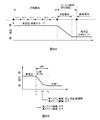
図5Aは、比較例における1ジョブの作業時間を説明する図であり、図5Bは、本実施形態における1ジョブの作業時間を説明する図である。ここで、印刷領域に位置するロール紙Rに対して画像を印刷する印刷動作から、新たなロール紙Rの部位を印刷領域に搬送する搬送動作までを、1ジョブと言う。また、印刷領域に位置するロール紙Rに対して、ヘッド33がX方向(ロール紙の搬送方向)に移動しながらロール紙Rにインクを吐出する動作を「1パス」と言う。パス間にヘッド33をY方向(ロール紙Rの幅方向)移動する動作を実行することで、ロール紙Rには2次元の画像が印刷される。以下、印刷領域に位置するロール紙Rに対して6回のパスで画像の印刷が完成する例を挙げて説明する。なお、画像の印刷が完成するパス数は、画像の大きさや印刷解像度によって変動する。
=== Printing operation ===
FIG. 5A is a diagram for explaining the working time of one job in the comparative example, and FIG. 5B is a diagram for explaining the working time of one job in the present embodiment. Here, from a printing operation for printing an image on the roll paper R positioned in the printing area to a conveyance operation for conveying a new roll paper R portion to the printing area is referred to as one job. Further, the operation of ejecting ink onto the roll paper R while the
比較例(図5A)では、プリンター1のコントローラー10は、印刷動作の間中ずっと(6パスの間中ずっと)高吸引モードの状態を維持させ、印刷動作の後に高吸引モードから低吸引モードに切り替える切替動作を実行させる。その後、高吸引モードから低吸引モードに完全に切り替わった後に、コントローラー10は搬送動作を実行させる。即ち、比較例における1ジョブの作業時間は、印刷動作に要する時間と、切替動作に要する時間と、搬送動作に要する時間の合計時間となり、1ジョブの作業時間が比較的に長い。
In the comparative example (FIG. 5A), the
前述のように、本実施形態のプリンター1では、低吸引モード時に、負圧室41内に負圧を発生させる2つのファン機構42,43のうちの一方のファン機構43を停止し、停止したファン機構43を空気孔として利用する。そうして、高吸引モードから低吸引モードへの切り替え時間を短縮する。しかし、切替動作の時間が短縮したといえども、比較例(図5A)のように、印刷以外の動作である切替動作のためだけに時間が取られると、効率的ではない。
よって、本実施形態では、全体の印刷作業時間を出来る限り短縮することを目的とする。
As described above, in the printer 1 of the present embodiment, one of the two
Therefore, an object of the present embodiment is to shorten the entire printing work time as much as possible.
そこで、本実施形態のプリンター1では(図5B)、コントローラー10は、搬送動作の前の動作中に、即ち、印刷動作中に、2つのファン機構42,43のうちの一方のファン機構43を停止することによって、高吸引モードから低吸引モードへの切り替えを行う(換言すると、負圧室41内の圧力を高負圧から低負圧に切り替える)。
Therefore, in the printer 1 of this embodiment (FIG. 5B), the
このようなプリンター1によれば(又は、このようなプリンター1による印刷方法によれば)、印刷動作と並行して切替動作が行われるため、切替動作のためだけの時間が取られることがなく、比較例に比べて全体の印刷作業時間を短縮することができる。具体的には、本実施形態における1ジョブの作業時間は、印刷動作に要する時間と搬送動作に要する時間の合計時間となり、比較例における1ジョブの作業時間に比べて、切替動作に要する時間分だけ短縮することが出来る。 According to such a printer 1 (or according to such a printing method by the printer 1), the switching operation is performed in parallel with the printing operation, so that only time for the switching operation is not taken. Compared with the comparative example, the entire printing work time can be shortened. Specifically, the work time of one job in the present embodiment is the total time of the time required for the printing operation and the time required for the transport operation, and is the time required for the switching operation compared to the work time of one job in the comparative example. Can only be shortened.
なお、ファン機構42,43のオン・オフを制御するだけでなく、ファン機構42の回転数を制御することによって、負圧室41内を所望の負圧に設定することができ、その結果、ロール紙Rに対する吸引力を所望の吸引力にすることができる。例えば、本実施形態では、高吸引モードにおいて、2つのファン機構42,43を共に100%の回転数で運転させることで負圧室41内を所望の高負圧(所望の高吸引力)にし、低吸引モードにおいて、第2ファン機構43を停止し(0%の回転数とし)、第1ファン機構42を65%の回転数で運転させることで負圧室41内を所望の低負圧(所望の低吸引力)にするとする。
In addition to controlling on / off of the
よって、コントローラー10は、高吸引モードから低吸引モードの切り替えの際に(切替動作の開始時に・図5BのT0に)、第2ファン機構43を停止し、且つ、第1ファン機構42の回転数を低吸引モードにおける吸引力に応じた回転数(ここでは65%の回転数)に設定する。そうすることで、容易な制御で、負圧室41内の圧力を高負圧から低負圧に安定して移行することができる。
Therefore, the
また、本実施形態では、コントローラー10は、印刷動作の後半に、高吸引モードから低吸引モードへの切替動作を開始する。例えば、図5Bに示すように、6回のパスで画像の印刷が完成する場合、コントローラー10は、4パス以降に、高吸引モードから低吸引モードに切り替える。なお、高吸引モードから低吸引モードへの切り替えは、パス間に行っても良いし、パスの途中で行っても良い。その結果、印刷動作中において高吸引モードである時間を長くすることができる。そうすることで、印刷動作中の長い時間に亘って、プラテン31上のロール紙Rを所定の位置に平坦な状態に保持することができ、印刷画像の画質劣化を抑制できる(インクの滲みやヘッド33との接触等を防止できる)。
In the present embodiment, the
更に、本実施形態では、コントローラー10は、印刷動作の終了時点(図5BのT1)から切替動作に要する時間(ta秒)を逆算した時点(T0)に、高吸引モードから低吸引モードへの切替動作を開始する。図5Bでは、切替動作に要する時間(ta秒)が2回のパスの印刷時間に相当するため、5パス目の開始時に切替動作を開始する。また、ここでは、6回のパスで画像の印刷が完成する例を挙げているが、例えば、4回のパスで画像の印刷が完成する場合には3パス目の開始時に切替動作を開始すればよく、また、16回のパスで画像の印刷が完成する場合には15パス目の開始時に切替動作を開始すればよい。その結果、印刷動作中において高吸引モードである時間をより長くすることができる。そうすることで、印刷動作中のより長い時間に亘って、プラテン31上のロール紙Rを所定の位置に平坦な状態に保持することができ、印刷画像の画質劣化を抑制できる。
Further, in the present embodiment, the
なお、高吸引モードから低吸引モードへの切替動作に要する時間(ta秒)は、プリンター1の設計時(プリンター1の機種ごと)や、プリンター1の製造時(プリンター1の個体ごと)に、決定するとよい。ただし、切替動作に要する時間に誤差が生じる場合もある。そこで、余裕度をもたせるために、印刷動作の終了時点(図5BのT1)から、切替動作に要する時間(ta秒)と誤差時間(α)の合計時間(ta+α)を逆算した時点に、切替動作を開始するようにしてもよい。そうすることで、高吸引モードから低吸引モードに確実に切り替わった状態で搬送動作を実行することができる。 The time required for switching from the high suction mode to the low suction mode (ta seconds) is determined when the printer 1 is designed (for each model of the printer 1) or when the printer 1 is manufactured (for each individual printer 1). It is good to decide. However, an error may occur in the time required for the switching operation. Therefore, in order to provide a margin, switching is performed from the time when the printing operation ends (T1 in FIG. 5B) to the time when the total time (ta + α) of the switching operation (ta seconds) and the error time (α) is calculated backward. The operation may be started. By doing so, the transfer operation can be executed in a state where the high suction mode is reliably switched to the low suction mode.
また、印刷動作の後に、定期的にメンテナンス動作(吐出不良検査・クリーニング動作)が実行される場合がある。前述のように、メンテナンス動作時には、低吸引モードに設定することで、振動や騒音を低減し、吐出不良検査の精度を上げることができる。そのため、本実施形態のように印刷動作中に高吸引モードから低吸引モードに切り替えることによって、印刷動作の終了後すぐにメンテナンス動作を実行することができる。よって、全体の印刷作業時間を短縮することができる。 Further, after the printing operation, a maintenance operation (ejection failure inspection / cleaning operation) may be periodically performed. As described above, by setting the low suction mode during the maintenance operation, vibration and noise can be reduced, and the accuracy of the ejection defect inspection can be increased. Therefore, the maintenance operation can be executed immediately after the end of the printing operation by switching from the high suction mode to the low suction mode during the printing operation as in the present embodiment. Therefore, the overall printing work time can be shortened.
===変形例===
図6A及び図6Bは、印刷動作の変形例を説明する図である。前述の実施形態(図5B)では、印刷動作の直ぐ後に搬送動作が実行される例を示しているが、これに限らない。印刷動作後に定期的にメンテナンス動作が実行され、その後に搬送動作が実行される場合がある。また、複数回おきの印刷動作の後、又は、全印刷動作の後に、何の動作も実行されない時間である「待ち時間」を設定することが可能なプリンター1がある。このようなプリンター1では、印刷動作後に待ち時間が設けられ、待ち時間の経過後に搬送動作が実行される。
=== Modification ===
6A and 6B are diagrams illustrating a modification of the printing operation. In the above-described embodiment (FIG. 5B), an example in which the transport operation is performed immediately after the printing operation is shown, but the present invention is not limited to this. In some cases, a maintenance operation is periodically performed after the printing operation, and then a conveyance operation is performed. In addition, there is a printer 1 that can set a “waiting time” that is a time during which no operation is performed after a plurality of printing operations or after all printing operations. In such a printer 1, a waiting time is provided after the printing operation, and the carrying operation is performed after the waiting time has elapsed.
そこで、変形例では、コントローラー10が、印刷動作中に高吸引モードから低吸引モードに切り替えるのではなく、図6Aに示すように、搬送動作の前の動作である「メンテナンス動作中」や「待ち時間中」に高吸引モードから低吸引モードに切り替えるようにする。そうすることで、印刷動作中はずっと高吸引モードに設定され、プラテン31上のロール紙Rを所定の位置に平坦な状態に保持することができ、印刷画像の画質劣化を抑制できる。また、印刷動作後に、切替動作が実行され、その後に、メンテナンス動作、又は、待ち時間が実行される場合に比べて、全体の印刷作業時間を短縮することができる。即ち、切替動作を他の動作(メンテナンス動作・待ち時間)と並行して実行するため、効率的となる。なお、図6Aでは、メンテナンス動作や待ち時間の開始と同時に切替動作を実行させているが、これに限らず、例えば、メンテナンス動作や待ち時間の後半に切替動作を実行させるようにしてもよい。
Therefore, in the modified example, the
また、前述の実施形態(図5B)では、高吸引モードから低吸引モードの切り替えの際に(切替動作の開始時に)、第2ファン機構43を停止し、且つ、第1ファン機構42の回転数を低吸引モードにおける吸引力に応じた回転数(65%の回転数)に設定しているが、これに限らない。
In the above-described embodiment (FIG. 5B), the
例えば、図6Bに示すように、コントローラー10が、高吸引モードから低吸引モードの切り替えの際に(切替動作の開始時に・図6BのT2に)、2つのファン機構42,43を停止し(オフ状態にし)、所定時間(tc秒)の経過後に(T3の時点で)、第1ファン機構42の回転数を低吸引モードにおける吸引力に応じた回転数(65%の回転数)に設定するようにしても良い。
For example, as shown in FIG. 6B, the
そうすることで、低吸引モードへの切り替え直後は(T2〜T3)、2つのファン機構42,43において大気開放され、負圧室41内の負圧をより早く下げることができる(圧力を上げることができる)。即ち、低吸引モードへの切り替え直後は2つのファン機構42,43(厳密には、2つのファン機構42,43の各吸込口と連通する負圧室41の開口部41d,41e)を空気孔として作用させる。そして、所定の時間経過後に(T3)、第1ファン機構42を65%の回転数で運転させることにより、負圧室41内の負圧を低吸引モードに対応した低負圧にすることができる。
By doing so, immediately after switching to the low suction mode (T2 to T3), the air is released to the atmosphere by the two
この変形例の切替動作に要する時間(図6Bのtb秒)の方が、前述の実施形態の切替動作に要する時間(図5Bのta秒)よりも短くすることができる。よって、搬送動作の前の動作において、高吸引モードである時間をより長くすることができる。搬送動作の前の動作が印刷動作であれば、より長い時間に亘ってロール紙Rを所定の位置に平坦な状態に保持することができ、印刷画像の画質劣化を抑制できる。ただし、前述の実施形態(図5B)の方が、制御が容易であり、高吸引モードから低吸引モードへの移行が安定する。 The time required for the switching operation in this modification (tb seconds in FIG. 6B) can be shorter than the time required for the switching operation in the above-described embodiment (ta seconds in FIG. 5B). Therefore, in the operation before the transport operation, the time during the high suction mode can be further increased. If the operation before the transport operation is a printing operation, the roll paper R can be held in a flat state at a predetermined position for a longer time, and deterioration of the image quality of the printed image can be suppressed. However, the above-described embodiment (FIG. 5B) is easier to control, and the transition from the high suction mode to the low suction mode is stable.
また、前述の実施形態(図5B)では、搬送動作の前の動作中に、高吸引モードから低吸引モードへ切り替えているが、これに限らない。比較例(図5A)のように、搬送動作の前の動作が終了した後に、高吸引モードから低吸引モードへ切り替えてもよい。この場合、搬送動作の前の動作が印刷動作であれば、印刷動作の間中ずっと高吸引モードが維持されるため、印刷画像の画質劣化を抑制できる。また、この場合、切替動作のためだけの時間が設定されるので、低吸引モードにおいて2つのファン機構42,43のうちの一方のファン機構43を停止して、停止したファン機構43を空気孔として利用し、高吸引モードから低吸引モードへの切替時間を短縮する発明がより有効となる。
In the above-described embodiment (FIG. 5B), the high suction mode is switched to the low suction mode during the operation before the transport operation, but this is not restrictive. As in the comparative example (FIG. 5A), the high suction mode may be switched to the low suction mode after the operation before the transport operation is completed. In this case, if the operation before the conveyance operation is a printing operation, the high suction mode is maintained throughout the printing operation, so that it is possible to suppress deterioration in image quality of the printed image. In this case, since only the time for the switching operation is set, one of the two
===その他の実施の形態===
本実施形態は、主として画像記録装置について記載されているが、画像記録方法等の開示も含まれる。また、本実施形態は、本発明の理解を容易にするためのものであり、本発明を限定して解釈するためのものではない。本発明は、その趣旨を逸脱することなく、変更、改良され得ると共に、本発明にはその等価物が含まれることは言うまでもない。特に、以下に述べる実施形態であっても、本発明に含まれるものである。
=== Other Embodiments ===
Although the present embodiment is mainly described with respect to an image recording apparatus, disclosure of an image recording method and the like is also included. Further, the present embodiment is intended to facilitate understanding of the present invention and is not intended to limit the present invention. The present invention can be changed and improved without departing from the gist thereof, and it is needless to say that the present invention includes equivalents thereof. In particular, the embodiments described below are also included in the present invention.
<プリンターについて>
前述の実施形態では、印刷領域に位置するロール紙Rに対して、ヘッド33をロール紙Rの搬送方向及び幅方向に移動させながら画像を印刷するプリンター1を例に挙げているが、これに限らない。例えば、固定されたヘッド33の下をロール紙Rが通過する際に画像を印刷するプリンターでもよい。
また、画像を記録する媒体はロール紙Rに限らず、単票紙でもよいし、ノズルからインク以外の他の流体を吐出することで媒体に画像を記録する画像記録装置であってもよい。
また、画像記録装置はプリンターに限らず、例えば、カラーフィルタ製造装置、染色装置、微細加工装置、半導体製造装置、表面加工装置、三次元造形機、気体気化装置、有機EL製造装置(特に高分子EL製造装置)、ディスプレイ製造装置、成膜装置、DNAチップ製造装置などのインクジェット技術を応用した各種の装置に、上述の実施形態と同様の技術を適用してもよい。また、これらの方法や製造方法も応用範囲の範疇である。
<About the printer>
In the above-described embodiment, the printer 1 that prints an image while moving the
Further, the medium for recording an image is not limited to the roll paper R, and may be a cut sheet, or an image recording apparatus that records an image on a medium by discharging a fluid other than ink from a nozzle.
Further, the image recording apparatus is not limited to a printer. For example, a color filter manufacturing apparatus, a staining apparatus, a fine processing apparatus, a semiconductor manufacturing apparatus, a surface processing apparatus, a three-dimensional modeling machine, a gas vaporization apparatus, an organic EL manufacturing apparatus (particularly a polymer The same technology as that of the above-described embodiment may be applied to various devices to which inkjet technology is applied such as an EL manufacturing device, a display manufacturing device, a film forming device, and a DNA chip manufacturing device. These methods and manufacturing methods are also within the scope of application.
1 プリンター、1a 天井部、 2 コンピューター、
10 コントローラー、11 インターフェース部、12 CPU、
13 メモリー、14 ユニット制御回路、
20 搬送ユニット、21a 供給ローラー、21b 供給ローラー、
22a 排出ローラー、22b 排出ローラー、23 巻取りローラー、
30 記録ユニット、31 プラテン、311 ヒーター、
32 キャリッジ、33 ヘッド、34 天井ファン、35 キャップ機構、
40 吸引ユニット、41 負圧室、42 第1ファン機構、
43 第2ファン機構、44 吸引孔、
50 検出器群、51 圧力センサー、
61 ファン、62 ファン、63 ファン、
1 Printer, 1a Ceiling, 2 Computer,
10 controller, 11 interface unit, 12 CPU,
13 memory, 14 unit control circuit,
20 transport unit, 21a supply roller, 21b supply roller,
22a discharge roller, 22b discharge roller, 23 take-up roller,
30 recording units, 31 platens, 311 heaters,
32 carriage, 33 head, 34 ceiling fan, 35 cap mechanism,
40 suction unit, 41 negative pressure chamber, 42 first fan mechanism,
43 Second fan mechanism, 44 suction hole,
50 detector groups, 51 pressure sensors,
61 fans, 62 fans, 63 fans,
Claims (7)
(B)前記媒体を搬送する搬送部と、
(C)吸引孔の開口部が設けられた支持面で前記媒体を支持する媒体支持部と、
(D)前記吸引孔を介して前記媒体支持部に支持された前記媒体を吸引する吸引部であって、前記吸引孔と連通する負圧室と、前記負圧室の内部の空気を吐き出して前記負圧室内に負圧を発生させる少なくとも2つの送風部と、を有し、前記負圧室の外面の異なる位置に前記少なくとも2つの送風部が取り付けられた吸引部と、
(E)前記媒体に対する前記吸引部の吸引力を第1の吸引力とする第1のモードと、前記吸引力を前記第1の吸引力よりも低い第2の吸引力とする第2のモードと、を切り替える制御部であって、
前記第2のモード時には、前記少なくとも2つの送風部のうちの1つの送風部を停止する制御部と、
(F)を備えたことを特徴とする画像記録装置。 (A) a recording unit for recording an image on a medium;
(B) a transport unit that transports the medium;
(C) a medium support unit that supports the medium on a support surface provided with an opening of a suction hole;
(D) A suction part that sucks the medium supported by the medium support part through the suction hole, and discharges the air inside the negative pressure chamber and the negative pressure chamber communicating with the suction hole. A suction unit having at least two air blowing units that generate negative pressure in the negative pressure chamber, and the at least two air blowing units attached to different positions on the outer surface of the negative pressure chamber;
(E) A first mode in which the suction force of the suction unit with respect to the medium is a first suction force, and a second mode in which the suction force is a second suction force lower than the first suction force. And a control unit for switching between
During the second mode, a control unit that stops one of the at least two blowing units,
An image recording apparatus comprising (F).
前記少なくとも2つの送風部のうちの一の送風部の吸込口と連通する前記負圧室の開口部を通過する風量の方が、他の送風部の吸込口と連通する前記負圧室の開口部を通過する風量よりも大きい、
画像記録装置。 The image recording apparatus according to claim 1,
The amount of air passing through the opening of the negative pressure chamber that communicates with the suction port of one of the at least two blowers is the opening of the negative pressure chamber that communicates with the suction port of the other blower Larger than the air volume passing through the section,
Image recording device.
前記制御部は、前記第2のモード時には、前記一の送風部を停止する、
画像記録装置。 The image recording apparatus according to claim 2,
The control unit stops the one air blowing unit in the second mode.
Image recording device.
前記一の送風部では、少なくとも2つの送風機が直列に取り付けられている、
画像記録装置。 The image recording apparatus according to claim 2 or 3, wherein
In the one air blowing unit, at least two blowers are attached in series.
Image recording device.
前記制御部は、前記記録部による前記媒体への画像の記録動作中に、前記第1のモードから前記第2のモードに切り替える、
画像記録装置。 The image recording apparatus according to any one of claims 1 to 4, wherein:
The control unit switches from the first mode to the second mode during an image recording operation on the medium by the recording unit.
Image recording device.
前記少なくとも2つの送風部は前記媒体支持部に直接的又は間接的に取り付けられている、
画像記録装置。 The image recording apparatus according to any one of claims 1 to 5, wherein:
The at least two air blowing units are directly or indirectly attached to the medium support unit,
Image recording device.
(B)前記媒体を搬送する搬送部と、
(C)吸引孔の開口部が設けられた支持面で前記媒体を支持する媒体支持部と、
(D)前記吸引孔を介して前記媒体支持部に支持された前記媒体を吸引する吸引部であって、前記吸引孔と連通する負圧室と、前記負圧室の内部の空気を吐き出して前記負圧室内に負圧を発生させる少なくとも2つの送風部と、を有し、前記負圧室の外面の異なる位置に前記少なくとも2つの送風部が取り付けられた吸引部と、
(E)前記媒体に対する前記吸引部の吸引力を第1の吸引力とする第1のモードと、前記吸引力を前記第1の吸引力よりも低い第2の吸引力とする第2のモードと、を切り替える制御部であって、
前記第2のモード時には、前記少なくとも2つの送風部のうちの1つの送風部を停止する制御部と、
(F)を備えた画像記録装置を用いて前記媒体に画像を記録することを特徴とする画像記録方法。 (A) a recording unit for recording an image on a medium;
(B) a transport unit that transports the medium;
(C) a medium support unit that supports the medium on a support surface provided with an opening of a suction hole;
(D) A suction part that sucks the medium supported by the medium support part through the suction hole, and discharges the air inside the negative pressure chamber and the negative pressure chamber communicating with the suction hole. A suction unit having at least two air blowing units that generate negative pressure in the negative pressure chamber, and the at least two air blowing units attached to different positions on the outer surface of the negative pressure chamber;
(E) A first mode in which the suction force of the suction unit with respect to the medium is a first suction force, and a second mode in which the suction force is a second suction force lower than the first suction force. And a control unit for switching between
During the second mode, a control unit that stops one of the at least two blowing units,
An image recording method comprising: recording an image on the medium using an image recording apparatus comprising (F).
Priority Applications (3)
| Application Number | Priority Date | Filing Date | Title |
|---|---|---|---|
| JP2010203215A JP2012056242A (en) | 2010-09-10 | 2010-09-10 | Image recording device and image recording method |
| US13/223,431 US8678579B2 (en) | 2010-09-10 | 2011-09-01 | Image recording device and image recording method |
| CN2011102742464A CN102398417A (en) | 2010-09-10 | 2011-09-09 | Image recording device and image recording method |
Applications Claiming Priority (1)
| Application Number | Priority Date | Filing Date | Title |
|---|---|---|---|
| JP2010203215A JP2012056242A (en) | 2010-09-10 | 2010-09-10 | Image recording device and image recording method |
Publications (2)
| Publication Number | Publication Date |
|---|---|
| JP2012056242A true JP2012056242A (en) | 2012-03-22 |
| JP2012056242A5 JP2012056242A5 (en) | 2013-10-10 |
Family
ID=45806306
Family Applications (1)
| Application Number | Title | Priority Date | Filing Date |
|---|---|---|---|
| JP2010203215A Pending JP2012056242A (en) | 2010-09-10 | 2010-09-10 | Image recording device and image recording method |
Country Status (3)
| Country | Link |
|---|---|
| US (1) | US8678579B2 (en) |
| JP (1) | JP2012056242A (en) |
| CN (1) | CN102398417A (en) |
Families Citing this family (10)
| Publication number | Priority date | Publication date | Assignee | Title |
|---|---|---|---|---|
| JP5565061B2 (en) * | 2010-04-14 | 2014-08-06 | セイコーエプソン株式会社 | Medium adsorption support device, medium transport device |
| JP6056395B2 (en) * | 2012-11-12 | 2017-01-11 | セイコーエプソン株式会社 | Liquid ejector |
| JP6060634B2 (en) * | 2012-11-12 | 2017-01-18 | セイコーエプソン株式会社 | Liquid ejector |
| JP6135103B2 (en) * | 2012-11-26 | 2017-05-31 | 株式会社リコー | Image forming apparatus |
| JP2014188907A (en) * | 2013-03-27 | 2014-10-06 | Seiko Epson Corp | Liquid jet apparatus |
| EP3256323B1 (en) * | 2015-02-12 | 2020-04-15 | Bobst Mex Sa | Web holding and stabilizing unit for printhead and printer equipped therewith |
| JP6736855B2 (en) * | 2015-09-09 | 2020-08-05 | セイコーエプソン株式会社 | Inkjet printer control method and printing apparatus |
| CN106739547B (en) * | 2016-09-06 | 2018-09-21 | 深圳汉华工业数码设备有限公司 | A kind of digital printing equipment |
| US10696065B2 (en) * | 2017-07-09 | 2020-06-30 | ColDesi Inc. | Platen assembly for textile decorating machines |
| CN110744930A (en) * | 2019-11-12 | 2020-02-04 | 联想万像(深圳)科技有限公司 | Laser and ink jet integrated machine |
Citations (5)
| Publication number | Priority date | Publication date | Assignee | Title |
|---|---|---|---|---|
| JP2002127515A (en) * | 2000-10-20 | 2002-05-08 | Canon Inc | Imaging apparatus |
| JP2004018151A (en) * | 2002-06-14 | 2004-01-22 | Seiko Epson Corp | Recording medium carrying device and recording device |
| JP2007160556A (en) * | 2005-12-09 | 2007-06-28 | Canon Inc | Inkjet recorder |
| JP2007313743A (en) * | 2006-05-25 | 2007-12-06 | Mimaki Engineering Co Ltd | Printing apparatus, conveying apparatus, and printing method |
| JP2008081317A (en) * | 2006-08-30 | 2008-04-10 | Olympus Corp | Image recording apparatus |
Family Cites Families (4)
| Publication number | Priority date | Publication date | Assignee | Title |
|---|---|---|---|---|
| JPH08197799A (en) | 1995-01-23 | 1996-08-06 | Mutoh Ind Ltd | Paper pressing mechanism for image forming apparatus |
| US7390085B2 (en) * | 2003-03-07 | 2008-06-24 | Seiko Epson Corporation | Medium transporting device and recording apparatus |
| JP2007152762A (en) * | 2005-12-06 | 2007-06-21 | Fujifilm Corp | Image recording device |
| JP5159590B2 (en) * | 2008-12-09 | 2013-03-06 | 富士フイルム株式会社 | Image forming method |
-
2010
- 2010-09-10 JP JP2010203215A patent/JP2012056242A/en active Pending
-
2011
- 2011-09-01 US US13/223,431 patent/US8678579B2/en not_active Expired - Fee Related
- 2011-09-09 CN CN2011102742464A patent/CN102398417A/en active Pending
Patent Citations (5)
| Publication number | Priority date | Publication date | Assignee | Title |
|---|---|---|---|---|
| JP2002127515A (en) * | 2000-10-20 | 2002-05-08 | Canon Inc | Imaging apparatus |
| JP2004018151A (en) * | 2002-06-14 | 2004-01-22 | Seiko Epson Corp | Recording medium carrying device and recording device |
| JP2007160556A (en) * | 2005-12-09 | 2007-06-28 | Canon Inc | Inkjet recorder |
| JP2007313743A (en) * | 2006-05-25 | 2007-12-06 | Mimaki Engineering Co Ltd | Printing apparatus, conveying apparatus, and printing method |
| JP2008081317A (en) * | 2006-08-30 | 2008-04-10 | Olympus Corp | Image recording apparatus |
Also Published As
| Publication number | Publication date |
|---|---|
| US20120062674A1 (en) | 2012-03-15 |
| US8678579B2 (en) | 2014-03-25 |
| CN102398417A (en) | 2012-04-04 |
Similar Documents
| Publication | Publication Date | Title |
|---|---|---|
| JP5644292B2 (en) | Image recording apparatus and image recording method | |
| JP2012056242A (en) | Image recording device and image recording method | |
| JP5707800B2 (en) | Image recording apparatus and image recording method | |
| US20230166513A1 (en) | Printing apparatus and printing method | |
| CN108437644B (en) | Printing apparatus and printing method of printing apparatus | |
| JP5556574B2 (en) | Image recording apparatus and image recording method | |
| JP6756186B2 (en) | Liquid drop ejection device, control device and control method | |
| JP2012020553A (en) | Recorder and control method of recorder | |
| US8820884B2 (en) | Recording device and recording device control method | |
| JP2009132500A (en) | Recording medium conveying device, and recording device including the same | |
| JP6907579B2 (en) | Printing device and printing method of printing device | |
| JP2009018427A (en) | Liquid jet apparatus, and cleaning method of liquid ejection head in liquid jet apparatus | |
| JP5754094B2 (en) | Recording apparatus and recording apparatus control method | |
| JP2013184426A (en) | Recording apparatus and color correcting method of recording apparatus | |
| JP5918716B2 (en) | Belt cleaning device and image forming apparatus | |
| JP5663992B2 (en) | Recording device | |
| US20190291472A1 (en) | Recording device | |
| JP2009018428A (en) | Liquid jet apparatus, and wiping method of liquid ejection head in liquid jet apparatus | |
| JP2004175063A (en) | Ink jet recorder | |
| JP7310205B2 (en) | LIQUID EJECTING APPARATUS AND DISPLAY CONTROL METHOD IN LIQUID EJECTING APPARATUS | |
| JP2020157547A (en) | Liquid discharge device and control method of liquid discharge device | |
| JP5871027B2 (en) | Recording device | |
| JP2012061621A (en) | Recording device and control method for the same |
Legal Events
| Date | Code | Title | Description |
|---|---|---|---|
| A521 | Request for written amendment filed |
Free format text: JAPANESE INTERMEDIATE CODE: A523 Effective date: 20130822 |
|
| A621 | Written request for application examination |
Free format text: JAPANESE INTERMEDIATE CODE: A621 Effective date: 20130822 |
|
| A977 | Report on retrieval |
Free format text: JAPANESE INTERMEDIATE CODE: A971007 Effective date: 20140416 |
|
| A131 | Notification of reasons for refusal |
Free format text: JAPANESE INTERMEDIATE CODE: A131 Effective date: 20140722 |
|
| A521 | Request for written amendment filed |
Free format text: JAPANESE INTERMEDIATE CODE: A523 Effective date: 20140905 |
|
| A02 | Decision of refusal |
Free format text: JAPANESE INTERMEDIATE CODE: A02 Effective date: 20141104 |