WO2021131998A1 - 水道工事管理システム、報知装置、水道工事管理方法、およびプログラム - Google Patents
水道工事管理システム、報知装置、水道工事管理方法、およびプログラム Download PDFInfo
- Publication number
- WO2021131998A1 WO2021131998A1 PCT/JP2020/047099 JP2020047099W WO2021131998A1 WO 2021131998 A1 WO2021131998 A1 WO 2021131998A1 JP 2020047099 W JP2020047099 W JP 2020047099W WO 2021131998 A1 WO2021131998 A1 WO 2021131998A1
- Authority
- WO
- WIPO (PCT)
- Prior art keywords
- work
- image
- waterworks
- notification content
- pipe
- Prior art date
- Legal status (The legal status is an assumption and is not a legal conclusion. Google has not performed a legal analysis and makes no representation as to the accuracy of the status listed.)
- Ceased
Links
Images











Classifications
-
- G—PHYSICS
- G06—COMPUTING OR CALCULATING; COUNTING
- G06Q—INFORMATION AND COMMUNICATION TECHNOLOGY [ICT] SPECIALLY ADAPTED FOR ADMINISTRATIVE, COMMERCIAL, FINANCIAL, MANAGERIAL OR SUPERVISORY PURPOSES; SYSTEMS OR METHODS SPECIALLY ADAPTED FOR ADMINISTRATIVE, COMMERCIAL, FINANCIAL, MANAGERIAL OR SUPERVISORY PURPOSES, NOT OTHERWISE PROVIDED FOR
- G06Q50/00—Information and communication technology [ICT] specially adapted for implementation of business processes of specific business sectors, e.g. utilities or tourism
- G06Q50/06—Energy or water supply
-
- G—PHYSICS
- G06—COMPUTING OR CALCULATING; COUNTING
- G06Q—INFORMATION AND COMMUNICATION TECHNOLOGY [ICT] SPECIALLY ADAPTED FOR ADMINISTRATIVE, COMMERCIAL, FINANCIAL, MANAGERIAL OR SUPERVISORY PURPOSES; SYSTEMS OR METHODS SPECIALLY ADAPTED FOR ADMINISTRATIVE, COMMERCIAL, FINANCIAL, MANAGERIAL OR SUPERVISORY PURPOSES, NOT OTHERWISE PROVIDED FOR
- G06Q50/00—Information and communication technology [ICT] specially adapted for implementation of business processes of specific business sectors, e.g. utilities or tourism
- G06Q50/08—Construction
Definitions
- the present invention relates to a waterworks management system, a notification device, a waterworks management method, and a program.
- Patent Document 1 Conventionally, in the management of waterworks, for example, as shown in Patent Document 1, it has been common to photograph a work target area and manage this work target area.
- Patent Document 1 in order to manage the waterworks, it is necessary for the manager to witness the waterworks site and to look around the waterworks site. Therefore, in the technique disclosed in Patent Document 1, a lot of manpower is required to manage the water supply work. Considering the education and guidance for ensuring a certain level of skill in the management of waterworks, the conventional technology described in Patent Document 1 and the like increases the cost required for the management of waterworks. It is difficult to say that it corresponds to the expected decrease in the working population in the near future.
- One aspect of the present invention is to realize a waterworks management system, a notification device, a waterworks management method, and a program capable of managing waterworks at low cost and with the minimum necessary personnel.
- the waterworks management system is a waterworks management system that manages the progress of waterworks in which pipes are installed, and includes a work target area in the waterworks.
- An image detection unit that detects a feature image from the captured image
- a work state estimation unit that estimates the current work state in the water supply work from the feature image detected by the image detection unit
- the work state estimation unit It is characterized in that it is provided with a notification content determination unit that determines the notification content for the persons involved in the water supply work in response to the estimated current working state.
- the waterworks management method is a waterworks management method for managing the progress of waterworks in which pipes are installed, and includes a work target area in the waterworks.
- PIP pipe-in-pipe
- FIG. 1 is a block diagram showing a schematic configuration of a water supply construction management system 101 according to an embodiment of the present invention.
- FIG. 2 is a block diagram showing a schematic configuration of the notification device 102 according to the embodiment of the present invention.
- the waterworks management system 101 manages the progress of waterworks. Waterworks include the steps of installing pipes.
- the notification device 102 notifies the persons involved in the water supply work in relation to the water supply work.
- An example of the notification device 102 is an electronic device possessed by a person involved in waterworks, and an example of this electronic device is a tablet and a smartphone. Further, the notification device 102 may be a personal computer for management.
- the waterworks management system 101 includes a camera 1 and a management device 2.
- the camera 1 has a photographing unit 3 and a communication unit 4.
- the management device 2 includes a communication unit 5, an image detection unit 6, a work state estimation unit 7, a notification content determination unit 8, an element estimation unit 9, an upper limit value estimation unit 10, a delay information addition unit 11, a lower limit value estimation unit 12, and It has a deficiency information addition unit 13.
- the notification device 102 includes a communication unit 14, a notification content acquisition unit 15, and a notification execution unit 16.
- the photographing unit 3 photographs at least the work target area in the waterworks.
- the photographing unit 3 may take a still image or may take a moving image. Multiple photographs may be taken within the same waterworks.
- the work target area (and thus the camera 1) may be fixed or may be movable in units of one shooting. In other words, the photographing unit 3 creates a photographed image including a work target area each time it photographs.
- the communication unit 4 of the camera 1 and the communication unit 5 of the management device 2 communicate with each other, so that the data of the captured image can be transferred from the camera 1 to the management device 2.
- the communication mode between the communication unit 4 and the communication unit 5 is preferably wireless, but may be wired.
- the image detection unit 6 detects a feature image from the captured image.
- the work state estimation unit 7 estimates the current work state in the waterworks from the feature image detected by the image detection unit 6.
- the notification content determination unit 8 determines the notification content to the persons involved in the water supply work in response to the current work state estimated by the work state estimation unit 7.
- Information indicating the content of the notification is also referred to as information on the content of the notification.
- the element estimation unit 9 estimates the elements that may affect the work time corresponding to the current work state from each information possessed by the water supply construction management system 101.
- the upper limit value estimation unit 10 estimates the upper limit value of the working time corresponding to the current working state based on the elements obtained from the estimation by the element estimation unit 9.
- the delay information addition unit 11 adds information related to the delay of the current work state to the previous notification content.
- the lower limit value estimation unit 12 estimates the lower limit value of the working time corresponding to the current working state based on the elements obtained from the estimation by the element estimation unit 9.
- the deficiency information addition unit 13 adds information related to the deficiency of the current work state to the previous notification content.
- the communication unit 5 of the management device 2 and the communication unit 14 of the notification device 102 communicate with each other, so that the management device 2 notifies the notification content information indicating the notification content determined by the notification content determination unit 8. It is possible to transfer to the device 102.
- the communication mode between the communication unit 5 and the communication unit 14 is preferably wireless, but may be wired.
- the notification content acquisition unit 15 acquires the notification content information.
- the notification execution unit 16 executes the notification corresponding to the notification content information acquired by the notification content acquisition unit 15. Examples of the notification executed by the notification execution unit 16 include a display on the display (not shown) of the notification device 102 and a voice output from the speaker (not shown) of the notification device 102.
- the open-cut method includes, for example, the following (1) to (7).
- the description will focus on the detection of the feature image and the determination of the notification content corresponding to each of the following (1) to (7).
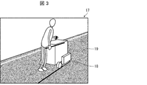
- FIG. 3 is an image diagram showing an example of a photographed image 17 in the asphalt cutting work according to the excavation method.
- the photographed image 17 shows that the asphalt cutter 18 cuts the asphalt 19 on the road to form cutting marks on the surface of the asphalt 19.
- the image detection unit 6 detects, for example, the image of the asphalt cutter 18 as a feature image from the captured image 17.
- the work state estimation unit 7 estimates from the image of the asphalt cutter 18 as a feature image that the current work state in the water supply work is the asphalt cutting work.
- the notification content determination unit 8 determines the notification content corresponding to the asphalt cutting work as the notification content to the persons involved in the water supply work. As an example of the notification content at this time, there is a content that the notification device 102 notifies that "the asphalt is being cut".
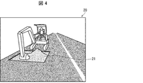
- FIG. 4 is an image diagram showing an example of a photographed image 20 in the asphalt demolition work related to the excavation method.
- the captured image 20 shows that the soil 21 is exposed from the backhoe bucket or the portion where the asphalt 19 (see FIG. 3) crushed by a pick or the like has been removed.
- the image detection unit 6 detects, for example, an image of soil 21 as a feature image from the captured image 20.
- the work state estimation unit 7 estimates from the image of the soil 21 as a feature image that the current work state in the waterworks is the asphalt demolition work.
- the notification content determination unit 8 determines the notification content corresponding to the asphalt demolition work as the notification content to the persons concerned with the water supply work. As an example of the notification content at this time, there is a content that the notification device 102 notifies that "the asphalt is being demolished".
- FIG. 5 is an image diagram showing an example of a photographed image 22 in the excavation (sheet pile installation) work related to the excavation method.
- the photographed image 22 shows that the earth and sand 23 generated when the soil 21 (see FIG. 4) is excavated by a backhoe or the like is loaded on the dump truck 24.
- the image detection unit 6 detects, for example, the image of the dump truck 24 as a feature image from the captured image 22.
- the work state estimation unit 7 estimates that the current work state in the water supply work is excavation (sheet pile installation) work from the image of the dump truck 24 as a feature image.
- the notification content determination unit 8 determines the notification content corresponding to the excavation (sheet sheet installation) work as the notification content to the persons concerned with the waterworks. As an example of the notification content at this time, there is a content that the notification device 102 notifies that "the ditch is being excavated".
- the element estimation unit 9 estimates the elements that may affect the work time corresponding to the excavation (sheet sheet installation) work from each information possessed by the water supply construction management system 101. This factor includes, for example, the work man-hours, the scale of equipment (example: the number of heavy machinery), the number of workers, and the work plan determined in advance based on the pipe layout, etc., corresponding to the excavation (sheet sheet installation) work. Can be mentioned.
- the upper limit value estimation unit 10 estimates the upper limit value of the working time corresponding to the excavation (sheet sheet installation) work based on the element.
- the delay information addition unit 11 adds information related to the delay of the excavation (sheet sheet installation) work to the previous notification content. To do. Factors that increase the work time in excavation (sheet sheet installation) work are that excavation is not proceeding smoothly due to the presence of existing buried objects (eg gas pipes or sewer pipes), and the depth of excavation is the initial depth. It may be that the schedule has been exceeded. Therefore, as an example of the information related to the delay, there is information that the notification device 102 notifies that "the existing buried object may exist" or "please check the excavation depth". Be done.
- FIG. 6 is an image diagram showing an example of a photographed image 25 in the hanging / installing work of the pipe according to the excavation method.
- the captured image 25 shows that the pipe 27 is suspended in or above the groove 26 by a sling belt or the like attached to the backhoe bucket.
- the image detection unit 6 detects, for example, the image of the tube 27 as a feature image from the captured image 25.
- the work state estimation unit 7 estimates from the image of the pipe 27 as a feature image that the current work state in the water supply work is the suspension / installation work of the pipe.
- the notification content determination unit 8 determines the notification content corresponding to the hanging / installing work of the pipe as the notification content to the persons concerned with the water supply work. As an example of the notification content at this time, there is a content that the notification device 102 notifies that "the pipe is being hung and installed".
- the element estimation unit 9 estimates the elements that may affect the work time corresponding to the hanging / installing work of the pipe from each information possessed by the water supply construction management system 101.
- This element includes, for example, the work man-hours, the scale of equipment (eg, the number of heavy machinery), the number of workers, and the work determined in advance based on the pipe layout, etc., corresponding to the hanging and installation work of the pipe. There is a plan. Further, examples of this element include the configuration of the pipe 27 (eg, type, size, shape of details).
- the upper limit value estimation unit 10 estimates the upper limit value of the working time corresponding to the hanging / installing work of the pipe based on the element.
- the delay information addition unit 11 provides information related to the delay of the pipe suspension / installation work with respect to the previous notification content. Is added.
- One of the factors that increase the working time in the hanging and installing work of the pipe is that the pipe is not installed smoothly due to the existence of the existing buried object. Therefore, as an example of the information related to the delay, there is information that the notification device 102 notifies that "an obstacle such as an existing buried object may have appeared".
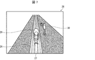
- FIG. 7 is an image diagram showing an example of a photographed image 28 in the joint joining and its check work according to the excavation method.
- the captured image 28 shows that the worker 29 enters the groove 26 and joins the joints of the two pipes 27 to each other, and another worker 30 writes the result of the joining on the groove 26. ing.
- the image detection unit 6 detects, for example, the images of the workers 29 and 30 as feature images from the captured image 28.
- the work state estimation unit 7 estimates from the images of the workers 29 and 30 as the feature images that the current work state in the water supply work is the joint joint and its check work.
- the notification content determination unit 8 determines the notification content corresponding to the joint joining and the check work as the notification content to the persons concerned with the water supply work. As an example of the notification content at this time, there is a content that the notification device 102 notifies that "joining / checking of the joint is in progress".
- the element estimation unit 9 estimates the elements that may affect the work time corresponding to the joint joining and its check work from each information possessed by the water supply construction management system 101.
- This element includes, for example, a joining method, a joining tool, a checking method, a checking tool, a work man-hour, a scale of equipment (eg, the number of heavy machinery), a number of workers, and a pipe corresponding to the joint joining and its check work.
- a work plan that has been decided in advance based on a plan, etc. can be mentioned.
- examples of this element include the configuration of the pipe 27 (eg, type, size, shape of details).
- the upper limit value estimation unit 10 estimates the upper limit value of the working time corresponding to the joint joining and the check work based on the element.
- the delay information addition unit 11 adds information related to the delay of the joint joint and its check work to the previous notification content. To do.
- One of the factors that increase the working time in joint joining and its check work is that there is a problem in joint joining. Therefore, as an example of the information related to the delay, there is information that the notification device 102 notifies "Please check the piping procedure".
- the lower limit value estimation unit 12 estimates the lower limit value of the working time corresponding to the joint joining and the check work based on the element.
- the deficiency information addition unit 13 is related to the speed (deficiency) of the joint joint and the check work with respect to the previous notification content. Add information. As a factor that shortens the working time in the joint joining and the check work thereof, there is an error in the joining procedure between the joints of the two pipes 27 and the like. Therefore, as an example of the information related to the speed, there is information that the notification device 102 notifies "Please confirm the joining procedure".
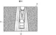
- FIG. 8 is an image diagram showing an example of a photographed image 31 in the backfilling / compacting work according to the excavation method.
- Rolling is the process of compacting the soil.
- the captured image 31 shows that the soil 32 is put into the groove 26 (see FIGS. 6 and 7) by a dump truck, a backhoe, or the like, and the rammer 33 or the like is used to roll the soil 32.
- the image detection unit 6 detects, for example, an image of soil 32 as a feature image from the captured image 31.
- the work state estimation unit 7 estimates from the image of the soil 32 as a feature image that the current work state in the water supply work is backfilling / rolling work.
- the notification content determination unit 8 determines the notification content corresponding to the backfilling / rolling work as the notification content to the persons involved in the water supply work. As an example of the notification content at this time, there is a content that the notification device 102 notifies that "backfilling / rolling is in progress".
- the element estimation unit 9 estimates the elements that may affect the work time corresponding to the backfilling / compaction work from each information possessed by the water supply construction management system 101. This factor includes, for example, the work man-hours, the scale of equipment (eg, the number of heavy machinery), the number of workers, and the work plan determined in advance based on the pipe layout, etc., corresponding to the backfilling and compaction work. Can be mentioned.
- the lower limit value estimation unit 12 estimates the lower limit value of the working time corresponding to the backfilling / rolling work based on the element.
- the deficiency information addition unit 13 adds information related to the deficiency of the backfilling / rolling work to the previous notification content. To do.
- One of the factors that shortens the work time in backfilling and compaction work is that the number of compaction times is less than originally planned. Therefore, as an example of the information related to the deficiency, there is information that the notification device 102 notifies "Please check the number of rolling compactions".
- FIG. 9 is an image diagram showing an example of a photographed image 34 in a temporary pavement according to the excavation method.
- the captured image 34 shows a new asphalt 35 having a color different from that of the asphalt 19, which is obtained by paving with a road roller, an asphalt finisher, a rammer 33 (see FIG. 8), or the like.
- the image detection unit 6 detects, for example, an image of the asphalt 35 as a feature image from the captured image 34.
- the work state estimation unit 7 estimates that the current work state in the water supply work is temporary pavement from the image of the asphalt 35 as the feature image.
- the notification content determination unit 8 determines the notification content corresponding to the temporary pavement as the notification content to the persons involved in the waterworks. As an example of the notification content at this time, there is a content that the notification device 102 notifies that "temporary pavement is in progress".
- the notification content determination unit 8 may add predetermined information related to the remaining time until the time when the road is scheduled to be released to the previous notification content.
- main pavement As an example of the work after the temporary pavement, there is a final pavement work called main pavement. This pavement is generally performed on or after the day after the temporary pavement because the thickness of the pavement varies depending on the type of road and it takes time to construct the pavement.
- the waterworks management system 101 may perform each of the above estimations by machine learning such as a neural network. This makes it possible to accurately detect a feature image whose position and the like change in time series, and the upper limit of the working time depends on factors that may affect the working time corresponding to the current working state. It may be possible to optimize the value or the lower limit.
- the upper limit value estimation unit 10 can update the upper limit value of the working time to a more suitable value each time the element is newly acquired.
- the lower limit value estimation unit 12 can update the lower limit value of the working time to a more suitable value each time the element is newly acquired.
- the operation of adding information related to the delay of the current working state to the notification content is performed by excavation (sheet sheet installation) work, pipe hanging / installation work, joint joining and its check work. However, this operation may be performed in other work in the waterworks.
- the operation of adding information related to the deficiency of the current working state to the notification content was performed in the joint joining and its check work, and the backfilling / rolling work. May be done in other work in waterworks. In addition, both of these operations may be performed in one operation in the waterworks.
- the propulsion method includes, for example, the following (8) to (18).
- the description will focus on the detection of the feature image and the determination of the notification content corresponding to each of the following (8) to (18).
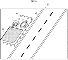
- FIG. 10 is an image diagram showing an example of a photographed image 36 in the excavation work of the starting pit and the reaching pit according to the propulsion method.
- the captured image 36 shows the following situation. That is, the backhoe 37 excavates the ground to form a shaft 38. The excavated soil is loaded onto the truck 39.
- the image detection unit 6 detects, for example, an image of the backhoe 37 and / or the shaft 38 as a feature image from the captured image 36.
- the work state estimation unit 7 estimates that the current work state in the water supply work is the excavation work of the starting shaft and the reaching shaft from the image of the backhoe 37 and / or the shaft 38 as the feature image.
- the notification content determination unit 8 determines the notification content corresponding to the excavation work of the starting pit and the reaching pit as the notification content to the persons concerned with the water supply work.
- the shaft 38 is either a starting shaft or an reaching shaft.
- the shaft 38 is a starting shaft, as an example of the notification content by the notification content determining unit 8, the content that the notification device 102 notifies that "the starting shaft is being excavated” can be mentioned.
- the shaft 38 is a reaching shaft, as an example of the notification content by the notification content determining unit 8, the content that the notification device 102 notifies that "the reaching shaft is being excavated” can be mentioned.
- an image of the backhoe 37 moving may be used as a feature image.
- the work state estimation unit 7 estimates the depth of the shaft 38 from the image of the shaft 38 as the feature image to perform the excavation work of the starting shaft and the reaching shaft. Progress may be estimated.
- the notification content by the notification content determination unit 8 based on the estimation, there is a content that the notification device 102 notifies that "the starting pit (or the reaching pit) is excavated to XX m". ..
- FIG. 11 is an image diagram showing an example of two captured images 42 (a) and 42 (b) in the jack carrying-in work according to the propulsion method.
- the two captured images 42 (a) and 42 (b) show that the main push jack 43 is carried into the starting pit 44 and the main push jack 43 is installed at the bottom of the starting pit 44.
- the starting shaft 44 corresponds to one shaft 38.
- the photographed image 42 (a) shows the state in which the main push jack 43 is being carried in
- the photographed image 42 (b) shows the installation state of the main push jack 43.
- the image detection unit 6 detects, for example, the image of the original push jack 43 as a feature image from the two captured images 42 (a) and 42 (b).
- the work state estimation unit 7 estimates from the image of the original push jack 43 as a feature image that the current work state in the water supply work is the carry-in work of the jack.
- the notification content determination unit 8 determines the notification content corresponding to the jack loading work as the notification content to the persons involved in the water supply work. As an example of the notification content at this time, there is a content that the notification device 102 notifies that "the main push jack is being installed in the starting pit".
- FIG. 12 is an image diagram showing an example of a photographed image 45 in the carrying-in and installation work of the excavator according to the propulsion method.
- the photographed image 45 shows a state in which the excavator 47 suspended by the crane 46 is lowered into the starting pit 44.
- the image detection unit 6 detects the images of the crane 46 and the excavator 47 as feature images from the captured image 45.
- the work state estimation unit 7 estimates from the images of the crane 46 and the excavator 47 as feature images that the current work state in the waterworks is the loading and installation work of the excavator.
- the notification content determination unit 8 determines the notification content corresponding to the carry-in and installation work of the excavator as the notification content to the persons concerned with the water supply work. As an example of the notification content at this time, there is a content that the notification device 102 notifies that "the excavator is being suspended".
- the work state estimation unit 7 indicates that the current work state in the waterworks is the carry-in and installation work of the excavator because the tension of the hanger 48 of the crane 46 and the state in which the excavator 47 is suspended. May be estimated.
- FIG. 13 is an image diagram showing an example of a photographed image 49 in the excavation work related to the propulsion method.
- the photographed image 49 shows the main push jack 43 and the excavator 47 installed in the starting pit 44.
- the image detection unit 6 detects the images of the main push jack 43 and the excavator 47 as feature images from the captured image 49.
- the work state estimation unit 7 estimates that the current work state in the water supply work is the excavation work from the images of the push jack 43 and the excavator 47 as the feature images.
- the notification content determination unit 8 determines the notification content corresponding to the excavation work as the notification content to the persons involved in the waterworks. As an example of the notification content at this time, there is a content that the notification device 102 notifies that "the excavator is being pushed".
- the element estimation unit 9 estimates the elements that may affect the work time corresponding to the excavation work from each information possessed by the water supply construction management system 101. Examples of this factor include the performance of the excavator 47 and the soil quality of the ground, which correspond to the excavation work.
- the upper limit value estimation unit 10 estimates the upper limit value of the working time corresponding to the excavation work based on the element. When the actual work time corresponding to the excavation work is longer than the upper limit value, the delay information addition unit 11 adds information related to the delay of the excavation work to the previous notification content.
- One of the factors that increase the work time in the excavation work is that some trouble has occurred during the excavation. Therefore, as an example of the information related to the delay, there is information that the notification device 102 notifies that "there is a possibility that a trouble has occurred in the excavation work".
- an image in which the main push jack 43 and / or the excavator 47 is moving may be used as a feature image, and the time and / or the time during which the excavator 47 is reflected in the captured image 49.
- an image in which the length in the traveling direction is not more than a predetermined value may be used as a feature image.
- FIG. 14 is an image diagram showing an example of the captured image 50 in the jack return operation 1 according to the propulsion method.
- the captured image 50 may be a still image, but here it is assumed to be a moving image.
- the captured image 50 shows that the time during which the excavator 47 is reflected is less than a predetermined time, the space 51 behind the excavator 47 is sufficiently large, and the stroke of the push jack 43 is shortened. ..
- the image detection unit 6 detects the state as a feature image from the captured image 50.
- the work state estimation unit 7 estimates that the current work state in the water supply work is the jack return work 1 from the appearance as a feature image.
- the notification content determination unit 8 determines the notification content corresponding to the jack return operation 1 as the notification content to the persons involved in the water supply work. As an example of the notification content at this time, there is a content that the notification device 102 notifies that "the piping is being prepared".
- FIG. 15 is an image diagram showing an example of a photographed image 52 in the pipe carrying-in work according to the propulsion method.
- the captured image 52 shows that the pipe 54 is being carried into the loading platform of the truck 53.
- the image detection unit 6 detects, for example, the images of the track 53 and the tube 54 as feature images from the captured image 52.
- the work state estimation unit 7 estimates that the current work state in the water supply work is the pipe loading work from the images of the truck 53 and the pipe 54 as the feature images.
- the notification content determination unit 8 determines the notification content corresponding to the pipe loading work as the notification content to the persons involved in the water supply work. As an example of the notification content at this time, there is a content that the notification device 102 notifies that "the pipe is being prepared".
- an image of the pipe 54 being unloaded from the loading platform of the truck 53 by a crane or the like may be used as a feature image.
- FIG. 16 is an image diagram showing an example of a photographed image 55 in the hanging and installing work of the pipe according to the propulsion method.
- the photographed image 55 shows a state in which a pipe 54 suspended by a crane (not shown) is lowered into the starting pit 44.
- the image detection unit 6 detects, for example, an image of the crane and the pipe 54 as a feature image from the captured image 55.
- the work state estimation unit 7 estimates from the image of the crane and the pipe 54 as the feature image that the current work state in the water supply work is the suspension and installation work of the pipe.
- the notification content determination unit 8 determines the notification content corresponding to the hanging and installation work of the pipe as the notification content to the persons concerned with the water supply work. As an example of the notification content at this time, there is a content that the notification device 102 notifies that "the pipe is being hung".
- the captured image 55 is a moving image
- an image of the crane suspending the pipe 54 and the pipe 54 descending into the starting pit 44 may be used as a feature image.
- the work state estimation unit 7 estimates that the current work state in the waterworks is the pipe suspension and installation work from the tension of the crane suspension and the appearance of the pipe 54 being suspended. You may. Further, in the captured image 55, an image in which the pipe 54 is reflected behind the excavator 47 may be used as a feature image.
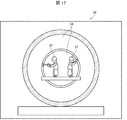
- FIG. 17 is an image diagram showing an example of a photographed image 56 in the pipe joining work according to the propulsion method.
- the photographed image 56 shows a worker 57 joining the joints of the two pipes 54 to each other.
- the image detection unit 6 detects the image of the worker 57 as a feature image from the captured image 56.
- the work state estimation unit 7 estimates from the image of the worker 57 as a feature image that the current work state in the water supply work is the pipe joining work.
- the notification content determination unit 8 determines the notification content corresponding to the pipe joining work as the notification content to the persons involved in the water supply work. As an example of the notification content at this time, there is a content that the notification device 102 notifies that "the pipes are being joined".
- the element estimation unit 9 estimates the elements that may affect the work time corresponding to the pipe joining work from each information possessed by the water supply construction management system 101. Examples of this element include the diameter and type of the pipe 54 corresponding to the pipe joining operation.
- the upper limit value estimation unit 10 estimates the upper limit value of the working time corresponding to the joining work of the pipes based on the element. When the actual work time corresponding to the pipe joining work is longer than the upper limit value, the delay information adding unit 11 adds information related to the delay of the pipe joining work to the previously notified content. One of the factors that increase the working time in the pipe joining work is that some trouble has occurred during the joining.
- the lower limit value estimation unit 12 estimates the lower limit value of the working time corresponding to the joining work of the pipes based on the element.
- the deficiency information addition unit 13 adds information related to the deficiency of the pipe joining work to the previously notified content.
- One of the factors that shortens the work time in the pipe joining work is that the joining work itself is inadequate. Therefore, as an example of the information related to the deficiency, there is information that the notification device 102 notifies "Please review the joint joining work procedure".
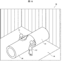
- FIG. 17 shows an example in which the worker 57 enters the pipe 54 and works, but as shown in FIG. 18, the worker 57 works from outside the pipe 54 in the starting pit 44. There may be cases where this is done.
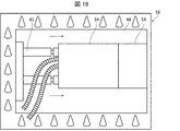
- FIG. 19 is an image diagram showing an example of a photographed image 58 in the pipe pushing operation according to the propulsion method.
- the captured image 58 may be a still image, but here it is assumed to be a moving image.
- the original push jack 43 moves, the excavator 47 moves out of the photographing range corresponding to the captured image 58 (that is, disappears from the captured image 58), and the range in which the tube 54 is reflected becomes smaller.
- the situation is shown.
- the image detection unit 6 detects the state as a feature image from the captured image 58.
- the work state estimation unit 7 estimates that the current work state in the water supply work is the pipe pushing work from the state as a feature image.
- the notification content determination unit 8 determines the notification content corresponding to the pipe pushing work as the notification content to the persons involved in the water supply work. As an example of the notification content at this time, there is a content that the notification device 102 notifies that "the pipe is being pushed".
- the element estimation unit 9 estimates an element that may affect the work time corresponding to the pipe pushing operation from each information possessed by the water supply construction management system 101. Examples of this element include the diameter and type of the pipe 54 corresponding to the pushing work of the pipe.
- the upper limit value estimation unit 10 estimates the upper limit value of the working time corresponding to the pushing work of the pipe based on the element.
- the delay information adding unit 11 adds information related to the delay of the pipe pushing work to the previous notification content.
- One of the factors that increase the working time in the pipe pushing work is that some trouble occurs during the pushing work. Therefore, as an example of the information related to the delay, there is information that the notification device 102 notifies that "there is a possibility that a trouble has occurred in the pushing operation".
- FIG. 20 is an image diagram showing an example of a photographed image 59 in the jack returning operation 2 according to the propulsion method.
- the jack return operation 2 is the same as the jack return operation 1 except that the excavator 47 is changed to the pipe 54.
- FIG. 21 is an image diagram showing an example of a photographed image 60 in the soil removal work according to the propulsion method.
- the captured image 60 shows the following situation. That is, the mud generated by excavating the ground is sent from the excavator 47 to the soil treatment plant 61.
- the soil treatment plant 61 treats this mud and discharges it into the bag 63 as soil discharge 62.
- the soil discharged 62 discharged into the bag 63 is carried to the truck by the backhoe 64.
- the image detection unit 6 detects the image of the soil removal 62 as a feature image from the captured image 60.
- the work state estimation unit 7 estimates that the current work state in the waterworks is the soil removal work from the image of the soil removal 62 as the feature image.
- the notification content determination unit 8 determines the notification content corresponding to the soil removal work as the notification content to the persons involved in the waterworks.
- the notification device 102 When the height of the soil discharged 62 discharged into the bag 63 is equal to or higher than a predetermined value, the notification device 102 notifies that "a truck needs to be dispatched" as an example of the notification content by the notification content determination unit 8. Can be mentioned.
- the notification device 102 When the height of the soil discharged 62 discharged into the bag 63 is less than a predetermined value, as an example of the content of the notification by the notification content determination unit 8, the notification device 102 notifies that "the amount of soil is appropriate". Can be mentioned.
- an image in which the soil excretion 62 is piled up on the truck bed may be used as a feature image.
- the pipes in the shield include, for example, the following (19) to (28).
- the description will focus on the detection of the feature image and the determination of the notification content corresponding to each of the following (19) to (28).
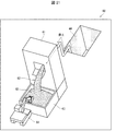
- FIG. 22 is an image diagram showing an example of a photographed image 65 in the hanging work of the shield machine, which relates to the piping in the shield (including the piping in the utility tunnel).
- the photographed image 65 shows how the shield machine 67 suspended by the crane 66 is lowered into the starting pit 68.
- the image detection unit 6 detects, for example, the images of the crane 66 and the shield machine 67 as feature images from the captured image 65.
- the work state estimation unit 7 estimates from the images of the crane 66 and the shield machine 67 as feature images that the current work state in the water supply work is the hanging work of the shield machine.
- the notification content determination unit 8 determines the notification content corresponding to the hanging work of the shield machine as the notification content to the persons involved in the water supply work. As an example of the notification content at this time, there is a content that the notification device 102 notifies that "the shield machine is being hung".
- the work state estimation unit 7 indicates that the current work state in the water supply work is the suspension work of the shield machine from the tension of the suspension tool 69 of the crane 66 and the appearance of the shield machine 67 being suspended. You may estimate.
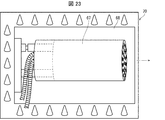
- FIG. 23 is an image diagram showing an example of a photographed image 70 in the excavation work related to the pipe in the shield (including the pipe in the utility tunnel).
- the captured image 70 shows the shield machine 67 installed in the starting pit 68.
- the image detection unit 6 detects, for example, an image of the shield machine 67 as a feature image from the captured image 70.
- the work state estimation unit 7 estimates that the current work state in the water supply work is excavation work from the image of the shield machine 67 as a feature image.
- the notification content determination unit 8 determines the notification content corresponding to the excavation work as the notification content to the persons involved in the waterworks. As an example of the notification content at this time, there is a content that the notification device 102 notifies that "the shield machine is being pushed".
- the element estimation unit 9 estimates the elements that may affect the work time corresponding to the excavation work from each information possessed by the water supply construction management system 101. Examples of this factor include the performance of the shield machine 67 and the soil quality of the ground, which correspond to the excavation work.
- the upper limit value estimation unit 10 estimates the upper limit value of the working time corresponding to the excavation work based on the element. When the actual work time corresponding to the excavation work is longer than the upper limit value, the delay information addition unit 11 adds information related to the delay of the excavation work to the previous notification content.
- One of the factors that increase the work time in the excavation work is that some trouble has occurred during the excavation. Therefore, as an example of the information related to the delay, there is information that the notification device 102 notifies that "there is a possibility that a trouble has occurred in the excavation work".
- an image of the shield machine 67 moving may be used as a feature image, or the time and / or the length in the traveling direction in which the shield machine 67 is reflected in the captured image 70 may be used as a feature image.
- An image that looks like a predetermined image or less may be used as a feature image.
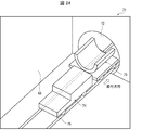
- FIG. 24 is an image diagram showing an example of a photographed image 71 in the segment carrying-in work related to the pipe in the shield (including the pipe in the utility tunnel).
- the captured image 71 shows a segment 73 brought behind the shield machine 67 (not visible because it is inside the shield tunnel 72 in FIG. 24).
- the image detection unit 6 detects, for example, the image of the segment 73 as a feature image from the captured image 71.
- the work state estimation unit 7 estimates from the image of the segment 73 as a feature image that the current work state in the water supply work is the carry-in work of the segment.
- the notification content determination unit 8 determines the notification content corresponding to the segment carry-in work as the notification content to the persons involved in the water supply work. As an example of the notification content at this time, there is a content that the notification device 102 notifies that "the segment is moving".
- an image of the segment 73 being brought behind the shield machine 67 may be used as a feature image, or the segment 73 mounted on the battery car 74 may be moved on the rail 75.
- the image may be a feature image.
- the work state estimation unit 7 may estimate that the current work state in the water supply work is the carry-in work of the segment from the appearance of the segment 73 reaching a predetermined position.
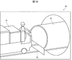
- FIG. 25 is an image diagram showing an example of a photographed image 76 in the shield tunnel construction work related to the pipe in the shield (including the pipe in the utility tunnel).
- the captured image 76 shows that the worker 77 is aligning the segment 73 using the Elector 78.
- the image detection unit 6 detects, for example, the images of the segment 73, the worker 77, and the erector 78 as feature images from the captured image 76.
- the work state estimation unit 7 estimates that the current work state in the water supply work is the shield tunnel construction work from the images of the segment 73, the worker 77, and the elector 78 as the feature images.
- the notification content determination unit 8 determines the notification content corresponding to the shield tunnel construction work as the notification content to the persons involved in the water supply work. As an example of the notification content at this time, there is a content that the notification device 102 notifies that "a shield tunnel is being constructed".
- the element estimation unit 9 estimates the elements that may affect the work time corresponding to the shield tunnel construction work from each information possessed by the water supply construction management system 101. Examples of this factor include the distance (length) of the shield tunnel corresponding to the construction work of the shield tunnel.
- the upper limit value estimation unit 10 estimates the upper limit value of the working time corresponding to the shield tunnel construction work based on the element. When the actual work time corresponding to the shield tunnel construction work is longer than the upper limit value, the delay information addition unit 11 adds information related to the delay of the shield tunnel construction work to the previous notification content.
- One of the factors that increase the work time in the shield tunnel construction work is that some trouble has occurred during the construction.
- the lower limit value estimation unit 12 estimates the lower limit value of the working time corresponding to the shield tunnel construction work based on the element.
- the deficiency information addition unit 13 adds information related to the deficiency of the shield tunnel construction work to the previous notification content.
- One of the factors that shortens the work time in the shield tunnel construction work is that the construction work itself is inadequate. Therefore, as an example of the information related to the deficiency, there is information that the notification device 102 notifies "Please review the procedure of the segment installation work".
- an image of the segment 73 being lifted by the crane 79 may be used as a feature image.
- the excavation work, the segment carry-in work, and the shield tunnel construction work are repeated in this order until the shield tunnel 72 is completed.
- the work of suspending the pipes related to the pipes in the shield is the same as the work of suspending and installing the pipes related to the propulsion method (see FIG. 16), except for the points related to the excavator 47. Since the form of can be applied, detailed description is not given here.
- FIG. 26 is an image diagram showing an example of a photographed image 80 in the pipe transportation work related to the pipe in the shield (including the pipe in the utility tunnel).
- the captured image 80 shows how the tube 81 on the battery car 74 moves on the rail 75.
- the image detection unit 6 detects, for example, the images of the battery car 74 and the tube 81 as feature images from the captured image 80.
- the work state estimation unit 7 estimates that the current work state in the water supply work is the pipe transportation work from the images of the battery car 74 and the pipe 81 as the feature images.
- the notification content determination unit 8 determines the notification content corresponding to the pipe transportation work as the notification content to the persons involved in the water supply work. As an example of the notification content at this time, there is a content that the notification device 102 notifies that "the pipe is being moved by the battery car".
- the element estimation unit 9 estimates the elements that may affect the work time corresponding to the pipe transportation work from each information possessed by the water supply construction management system 101.
- This element includes, for example, the distance of a predetermined section in a shield tunnel (consisting of a straight section and / or a curved section) corresponding to a pipe transport operation.
- the upper limit value estimation unit 10 estimates the upper limit value of the working time corresponding to the pipe transportation work based on the element.
- the delay information addition unit 11 adds information related to the delay of the pipe transport work to the previous notification content.
- One of the factors that increase the working time in the pipe transportation work is that some trouble has occurred during the transportation. Therefore, as an example of the information related to the delay, there is information that the notification device 102 notifies that "there is a possibility that a trouble has occurred in the pipe transportation work".
- the work state estimation unit 7 may estimate that the current work state in the water supply work is the pipe transportation work from the appearance of the pipe 81 reaching a predetermined position. ..
- the captured image in the battery car return work related to the piping inside the shield is a moving image
- the image detection unit 6 detects an image of the battery car 74 as a feature image from the captured image.
- the work state estimation unit 7 estimates from the image of the battery car 74 as a feature image that the current work state in the water supply work is the return work of the battery car.
- the notification content determination unit 8 determines the notification content corresponding to the return work of the battery car as the notification content to the persons involved in the water supply work. As an example of the notification content at this time, there is a content that the notification device 102 notifies that "the battery car is moving".
- the work state estimation unit 7 starts the water supply work from the state where the battery car 74 reaches a predetermined position. It may be presumed that the current working state in is the returning work of the battery car.
- the pipe loading work, pipe hanging work, pipe transport work, pipe joining work, and battery car return work are repeated in this order until the construction of the water pipe is completed.
- the PIP method includes, for example, the following (29) to (37). In the following, the description will focus on the detection of the feature image and the determination of the notification content corresponding to each of the following (29) to (37).
- the cutting work of the existing pipe related to the PIP method is the work of cutting the old pipe (existing pipe) installed in advance, but detailed explanation is not given here.
- FIG. 27 is an image diagram showing an example of a photographed image 82 in the band attaching work according to the PIP method.
- the captured image 82 shows that a band 84 for transmitting thrust to the pipes 83 is provided at the joint portion of the two pipes 83.
- the image detection unit 6 detects, for example, an image of the band 84 as a feature image from the captured image 82.
- the work state estimation unit 7 estimates from the image of the band 84 as a feature image that the current work state in the water supply work is the band attachment work.
- the notification content determination unit 8 determines the notification content corresponding to the band attachment work as the notification content to the persons involved in the waterworks. As an example of the notification content at this time, there is a content that the notification device 102 notifies that "the band is being constructed".
- the band attachment work related to the PIP method can be omitted.
- the notification device 102 notifies that "the band has not been constructed" as an example of the notification content by the notification content determination unit 8. The contents of.
- the pipe pushing work according to the PIP method is the work of pushing the pipe 83 (see FIG. 27) into the existing pipe.
- the same form as the pipe pushing work related to the propulsion method can be applied except for the point related to the excavator 47. No explanation will be given.
- the same form as the jack return work 2 (see FIG. 20) related to the propulsion method can be applied, so detailed explanation is not given here.
- the cutting work related to the PIP method is the work of cutting the pipe 83 and adjusting the total length of the water pipe.
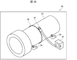
- FIG. 28 is an image diagram showing an example of a photographed image 85 in the cutting pipe work according to the PIP method.
- the captured image 85 shows the tube cutting tool 86 and its peripherals.
- the peripheral device include an engine 87 for driving the pipe cutting tool 86, a guide ring 88 for guiding the blade of the pipe cutting tool 86, and a roller cradle 89 for rotating the pipe 83.
- the image detection unit 6 detects an image of the pipe cutting tool 86 and the peripheral device as a feature image from the captured image 85.
- the work state estimation unit 7 estimates that the current work state in the water supply work is the pipe cutting work from the image of the pipe cutting tool 86 and the peripheral device as a feature image.
- the notification content determination unit 8 determines the notification content corresponding to the pipe cutting work as the notification content to the persons involved in the water supply work. As an example of the notification content at this time, there is a content that the notification device 102 notifies that "cutting work is in progress".
- the element estimation unit 9 estimates the elements that may affect the work time corresponding to the cutting work from each information possessed by the water supply construction management system 101. Examples of this element include the nominal diameter of the pipe 83, which corresponds to the cutting work.
- the upper limit value estimation unit 10 estimates the upper limit value of the working time corresponding to the cutting work based on the element. When the actual work time corresponding to the cutting work is longer than the upper limit value, the delay information adding unit 11 adds information related to the delay of the cutting work to the previous notification content. One of the factors that increase the working time in the cutting work is that some trouble has occurred during the cutting. Therefore, as an example of the information related to the delay, there is information that the notification device 102 notifies that "there is a possibility that a trouble has occurred in the cutting work".
- the cutting pipe work is not limited to the PIP method, but also in other water supply works where pipes are installed, such as the excavation method, the earthquake-resistant water tank construction, the propulsion method, and the piping inside the shield (including the piping inside the utility tunnel). It is common to be implemented.
- the waterworks management system 101 it is possible to determine the content of notification to the persons involved in the waterworks according to the current work state. As a result, the waterworks can be managed by simply notifying the person concerned of the contents of the notification by using, for example, the notification device 102, without the administrator having to witness the waterworks site or patrol the waterworks site. be able to. Therefore, according to the waterworks management system 101, the manpower required for the management of the waterworks can be reduced, so that the waterworks can be managed at low cost and with the minimum necessary personnel.
- the element estimation unit 9, the upper limit value estimation unit 10, and the delay information addition unit 11 are applied, if a delay occurs in the current working state, that fact can be added to the notification content.
- the element estimation unit 9, the lower limit value estimation unit 12, and the deficiency information addition unit 13 are applied, if a deficiency occurs in the current working state, that fact can be added to the notification content.
- the waterworks management method corresponding to the configuration of the waterworks management system 101 is also included in the category of the present invention.
- the waterworks management method is a waterworks management method for managing the progress of waterworks in which pipes are installed, and is an image that detects a feature image from a photographed image including a work target area in the waterworks.
- the work state estimation process that estimates the current work state in the waterworks from the detection process and the feature image detected in the image detection process, and the current work state estimated in the work state estimation process.
- the notification content determination step of determining the notification content to the persons concerned with the water supply work is included.
- Each control block of the water supply construction management system 101 may be realized by a logic circuit (hardware) formed in an integrated circuit (IC chip) or the like, or may be realized by software. ..
- the waterworks management system 101 includes a computer that executes a program command, which is software that realizes each function.
- the computer includes, for example, one or more processors and a computer-readable recording medium that stores the program. Then, in the computer, the object of the present invention is achieved by the processor reading the program from the recording medium and executing the program.
- the processor for example, a CPU (Central Processing Unit) can be used.
- the recording medium in addition to a “non-temporary tangible medium” such as a ROM (Read Only Memory), a tape, a disk, a card, a semiconductor memory, a programmable logic circuit, or the like can be used.
- a RAM Random Access Memory
- the program may be supplied to the computer via an arbitrary transmission medium (communication network, broadcast wave, etc.) capable of transmitting the program.
- a transmission medium communication network, broadcast wave, etc.
- one aspect of the present invention can also be realized in the form of a data signal embedded in a carrier wave, in which the program is embodied by electronic transmission.
- examples of the pipe include a ductile cast iron pipe (an example of a water pipe), a steel pipe, a vinyl chloride pipe, a polyethylene pipe, a Hume pipe and the like.
- the water supply construction management system 101 can be applied to the piping construction of the pipe.
- the water supply work here refers to the work of water supply (including water supply equipment), sewerage, industrial water supply, and agricultural water supply.
- the waterworks management system is a waterworks management system that manages the progress of waterworks for installing pipes, and detects a feature image from a photographed image including a work target area in the waterworks.
- the work state estimation unit that estimates the current work state in the water supply work from the image detection unit and the feature image detected by the image detection unit, and the current work state estimated by the work state estimation unit. Therefore, it is characterized in that it is provided with a notification content determination unit that determines the notification content for the persons involved in the water supply work.
- the waterworks management method is a waterworks management method for managing the progress of waterworks in which pipes are installed, and a feature image is detected from a photographed image including a work target area in the waterworks.
- the work state estimation step of estimating the current work state in the water supply work from the image detection step to be performed and the feature image detected in the image detection step, and the current work state estimated in the work state estimation process.
- it is characterized in that it includes a notification content determination step of determining the notification content to the persons concerned with the water supply work.
- the water supply work can be managed without the manager witnessing the water supply work site and patrolling the water supply work site, etc., simply by notifying the relevant person concerned of the content of the notification. Therefore, according to the above configuration, the manpower required for the management of the waterworks can be reduced, so that the waterworks can be managed at low cost and with the minimum necessary personnel.
- the waterworks management system includes an element estimation unit that estimates elements that may affect the work time corresponding to the current work state from each information possessed by the waterworks management system, and the above-mentioned element estimation unit.
- the upper limit value estimation unit that estimates the upper limit value of the work time based on the element obtained from the estimation by the element estimation unit and the actual work time corresponding to the current work state are longer than the upper limit value. It is preferable to include a delay information addition unit that adds information related to the delay of the current working state to the notification content.
- the waterworks management system includes an element estimation unit that estimates elements that may affect the work time corresponding to the current work state from each information possessed by the waterworks management system, and the above-mentioned element estimation unit.
- the lower limit value estimation unit that estimates the lower limit value of the working time based on the element obtained from the estimation by the element estimation unit and the actual working time corresponding to the current working state are shorter than the lower limit value.
- the notification content is provided with a deficiency information addition unit that adds information related to the deficiency of the current working state.
- the waterworks management system preferably performs each of the above estimations by machine learning.
- the notification device includes a notification content acquisition unit that acquires notification content information indicating the notification content determined by the notification content determination unit in the water supply construction management system, and a notification acquired by the notification content acquisition unit. It is equipped with a notification execution unit that executes notifications corresponding to the content information.
- the program according to one aspect of the present invention is a program for operating a computer as each part in the waterworks management system.
- Notification execution unit 101 Waterworks Management system 102 Notification device
Landscapes
- Business, Economics & Management (AREA)
- Health & Medical Sciences (AREA)
- Engineering & Computer Science (AREA)
- Economics (AREA)
- Physics & Mathematics (AREA)
- General Health & Medical Sciences (AREA)
- Human Resources & Organizations (AREA)
- Marketing (AREA)
- Primary Health Care (AREA)
- Strategic Management (AREA)
- Tourism & Hospitality (AREA)
- General Business, Economics & Management (AREA)
- General Physics & Mathematics (AREA)
- Theoretical Computer Science (AREA)
- Water Supply & Treatment (AREA)
- Public Health (AREA)
- Management, Administration, Business Operations System, And Electronic Commerce (AREA)
Abstract
低コストかつ必要最低限の人員で水道工事の管理を可能とする。水道工事管理システム(101)は、水道工事における作業対象領域が含まれる撮影画像から、特徴画像を検出する画像検出部(6)と、特徴画像から、水道工事における現在の作業状態を推定する作業状態推定部(7)と、現在の作業状態に対応して、水道工事の関係者に対する報知内容を決定する報知内容決定部(8)とを備えている。
Description
本発明は、水道工事管理システム、報知装置、水道工事管理方法、およびプログラムに関する。
従来、水道工事の管理においては、例えば、特許文献1に示されるように、作業対象領域を撮影し、この作業対象領域を管理することが一般的であった。
しかしながら、特許文献1に開示されている技術においては、水道工事を管理するために、管理者による、水道工事現場への立会いおよび水道工事現場の見回り等が必要である。このため、特許文献1に開示されている技術においては、水道工事の管理に多くの人手が必要となる。そして、水道工事の管理について一定レベルのスキルを担保するための教育や指導のことまで含めて考えると、特許文献1等に記載されている従来技術は、水道工事の管理に必要なコストを増大させる可能性もあり、近い将来に予想されている労働人口の減少に対応しているものであるとは言い難い側面がある。
本発明の一態様は、低コストかつ必要最低限の人員で水道工事の管理が可能な、水道工事管理システム、報知装置、水道工事管理方法、およびプログラムを実現することを目的とする。
前記の課題を解決するために、本発明の一態様に係る水道工事管理システムは、管を設置する水道工事の進捗を管理する水道工事管理システムであって、前記水道工事における作業対象領域が含まれる撮影画像から、特徴画像を検出する画像検出部と、前記画像検出部により検出される特徴画像から、前記水道工事における現在の作業状態を推定する作業状態推定部と、前記作業状態推定部により推定された現在の作業状態に対応して、前記水道工事の関係者に対する報知内容を決定する報知内容決定部とを備えていることを特徴としている。
前記の課題を解決するために、本発明の一態様に係る水道工事管理方法は、管を設置する水道工事の進捗を管理する水道工事管理方法であって、前記水道工事における作業対象領域が含まれる撮影画像から、特徴画像を検出する画像検出工程と、前記画像検出工程にて検出される特徴画像から、前記水道工事における現在の作業状態を推定する作業状態推定工程と、前記作業状態推定工程にて推定された現在の作業状態に対応して、前記水道工事の関係者に対する報知内容を決定する報知内容決定工程とを含んでいることを特徴としている。
本発明の一態様によれば、低コストかつ必要最低限の人員で水道工事の管理が可能となる。
図1は、本発明の実施の形態に係る水道工事管理システム101の概略構成を示すブロック図である。図2は、本発明の実施の形態に係る報知装置102の概略構成を示すブロック図である。
水道工事管理システム101は、水道工事の進捗を管理するものである。水道工事は、管を設置するステップを含んでいる。報知装置102は、水道工事の関係者に対して、水道工事に関連する報知を行うものである。報知装置102の一例として、水道工事の関係者が所持する電子機器が挙げられ、さらにこの電子機器の一例として、タブレットおよびスマートフォンが挙げられる。また、報知装置102は、管理用のパーソナルコンピュータであってもよい。
水道工事管理システム101は、カメラ1、および管理装置2を備えている。カメラ1は、撮影部3、および通信部4を有している。管理装置2は、通信部5、画像検出部6、作業状態推定部7、報知内容決定部8、要素推定部9、上限値推定部10、遅延情報付加部11、下限値推定部12、および不備情報付加部13を有している。報知装置102は、通信部14、報知内容取得部15、および報知実行部16を備えている。
撮影部3は、水道工事における少なくとも作業対象領域を撮影するものである。撮影部3は、静止画像を撮影してもよいし、動画像を撮影してもよい。同一の水道工事内で、複数回の撮影が行われてもよい。作業対象領域(ひいては、カメラ1)は、固定であってもよいし、1回の撮影を単位として可動であってもよい。換言すれば、撮影部3は、自身による撮影の度に、作業対象領域が含まれる撮影画像を作成するものである。
カメラ1の通信部4と管理装置2の通信部5とは、互いに通信しており、これにより、撮影画像のデータを、カメラ1から管理装置2へと転送することが可能である。通信部4と通信部5との通信形態は、無線であることが好ましいが、有線であってもよい。
画像検出部6は、撮影画像から、特徴画像を検出する。作業状態推定部7は、画像検出部6により検出される特徴画像から、水道工事における現在の作業状態を推定する。報知内容決定部8は、作業状態推定部7により推定された現在の作業状態に対応して、水道工事の関係者に対する報知内容を決定する。この報知内容を示す情報を、報知内容情報とも言う。
要素推定部9は、水道工事管理システム101が所有する各情報から、現在の作業状態に対応する作業時間に影響を及ぼし得る要素を推定する。上限値推定部10は、要素推定部9による推定から得られた要素に基づいて、現在の作業状態に対応する作業時間の上限値を推定する。遅延情報付加部11は、現在の作業状態に対応する実際の作業時間が当該上限値より長い場合、先の報知内容に対して、現在の作業状態の遅延に関連する情報を付加する。
下限値推定部12は、要素推定部9による推定から得られた要素に基づいて、現在の作業状態に対応する作業時間の下限値を推定する。不備情報付加部13は、現在の作業状態に対応する実際の作業時間が当該下限値より短い場合、先の報知内容に対して、現在の作業状態の不備に関連する情報を付加する。
管理装置2の通信部5と報知装置102の通信部14とは、互いに通信しており、これにより、報知内容決定部8により決定された報知内容を示す報知内容情報を、管理装置2から報知装置102へと転送することが可能である。通信部5と通信部14との通信形態は、無線であることが好ましいが、有線であってもよい。
報知内容取得部15は、報知内容情報を取得する。報知実行部16は、報知内容取得部15が取得した報知内容情報に対応する報知を実行する。報知実行部16が実行する報知の一例として、報知装置102のディスプレイ(図示しない)への表示、および報知装置102のスピーカー(図示しない)からの音声出力が挙げられる。
より具体的な、水道工事管理システム101の動作例について説明する。水道工事の種類として、例えば、下記(A)~(E)が挙げられる。
(A)開削工法
(B)耐震型貯水槽工事
(C)推進工法
(D)シールド内配管(共同溝内配管を含む)
(E)PIP工法
以下では、上記(A)~(E)のそれぞれにおける、水道工事管理システム101の動作例について説明する。なお、水道工事管理システム101は、以下に述べる例に限らず、水管橋の施工等にも適用可能である。
(B)耐震型貯水槽工事
(C)推進工法
(D)シールド内配管(共同溝内配管を含む)
(E)PIP工法
以下では、上記(A)~(E)のそれぞれにおける、水道工事管理システム101の動作例について説明する。なお、水道工事管理システム101は、以下に述べる例に限らず、水管橋の施工等にも適用可能である。
(A)開削工法
開削工法は、例えば、下記(1)~(7)を含んでいる。以下では、下記(1)~(7)のそれぞれに対応する、特徴画像の検出~報知内容の決定を中心に説明を行う。
開削工法は、例えば、下記(1)~(7)を含んでいる。以下では、下記(1)~(7)のそれぞれに対応する、特徴画像の検出~報知内容の決定を中心に説明を行う。
(1)アスファルトの切断作業
(2)アスファルトの取り壊し作業
(3)掘削(矢板設置)作業
(4)管の吊り下ろし・据付け作業
(5)継手接合およびそのチェック作業
(6)埋戻し・転圧作業
(7)仮舗装
図3は、開削工法に係る、アスファルトの切断作業における撮影画像17の一例を示すイメージ図である。撮影画像17には、アスファルトカッター18によって道路上のアスファルト19を切断することで、アスファルト19の表面に切断の跡が形成されている様子が示されている。画像検出部6は例えば、撮影画像17から、アスファルトカッター18の画像を特徴画像として検出する。作業状態推定部7は、特徴画像としてのアスファルトカッター18の画像から、水道工事における現在の作業状態がアスファルトの切断作業であることを推定する。報知内容決定部8は、アスファルトの切断作業に対応した報知内容を、水道工事の関係者に対する報知内容として決定する。このときの報知内容の一例として、報知装置102によって「アスファルトの切断中です」と報知させる旨の内容が挙げられる。
(2)アスファルトの取り壊し作業
(3)掘削(矢板設置)作業
(4)管の吊り下ろし・据付け作業
(5)継手接合およびそのチェック作業
(6)埋戻し・転圧作業
(7)仮舗装
図3は、開削工法に係る、アスファルトの切断作業における撮影画像17の一例を示すイメージ図である。撮影画像17には、アスファルトカッター18によって道路上のアスファルト19を切断することで、アスファルト19の表面に切断の跡が形成されている様子が示されている。画像検出部6は例えば、撮影画像17から、アスファルトカッター18の画像を特徴画像として検出する。作業状態推定部7は、特徴画像としてのアスファルトカッター18の画像から、水道工事における現在の作業状態がアスファルトの切断作業であることを推定する。報知内容決定部8は、アスファルトの切断作業に対応した報知内容を、水道工事の関係者に対する報知内容として決定する。このときの報知内容の一例として、報知装置102によって「アスファルトの切断中です」と報知させる旨の内容が挙げられる。
図4は、開削工法に係る、アスファルトの取り壊し作業における撮影画像20の一例を示すイメージ図である。撮影画像20には、バックホーのバケット、またはピック等によって砕かれたアスファルト19(図3参照)が取り除かれた部分から、土21が露出している様子が示されている。画像検出部6は例えば、撮影画像20から、土21の画像を特徴画像として検出する。作業状態推定部7は、特徴画像としての土21の画像から、水道工事における現在の作業状態がアスファルトの取り壊し作業であることを推定する。報知内容決定部8は、アスファルトの取り壊し作業に対応した報知内容を、水道工事の関係者に対する報知内容として決定する。このときの報知内容の一例として、報知装置102によって「アスファルトの取り壊し中です」と報知させる旨の内容が挙げられる。
図5は、開削工法に係る、掘削(矢板設置)作業における撮影画像22の一例を示すイメージ図である。撮影画像22には、バックホー等によって土21(図4参照)を掘削した際に生じた土砂23が、ダンプトラック24に積み込まれている様子が示されている。画像検出部6は例えば、撮影画像22から、ダンプトラック24の画像を特徴画像として検出する。作業状態推定部7は、特徴画像としてのダンプトラック24の画像から、水道工事における現在の作業状態が掘削(矢板設置)作業であることを推定する。報知内容決定部8は、掘削(矢板設置)作業に対応した報知内容を、水道工事の関係者に対する報知内容として決定する。このときの報知内容の一例として、報知装置102によって「溝の掘削中です」と報知させる旨の内容が挙げられる。
また、要素推定部9は、水道工事管理システム101が所有する各情報から、掘削(矢板設置)作業に対応する作業時間に影響を及ぼし得る要素を推定する。この要素としては例えば、掘削(矢板設置)作業に対応する、作業工数、設備の規模(例:重機の数)、および作業人数、さらには、管割図等に基づき事前に決められた作業計画が挙げられる。上限値推定部10は、当該要素に基づいて、掘削(矢板設置)作業に対応する作業時間の上限値を推定する。遅延情報付加部11は、掘削(矢板設置)作業に対応する実際の作業時間が当該上限値より長い場合、先の報知内容に対して、掘削(矢板設置)作業の遅延に関連する情報を付加する。掘削(矢板設置)作業において作業時間が長くなる要因として、既設埋設物(例:ガス管または下水管)の存在に起因して掘削が円滑に進んでいないこと、および掘削の深さが当初の予定を超えていること、等が挙げられる。そこで、当該遅延に関連する情報の一例として、報知装置102によって「既設埋設物が存在している可能性があります」または「掘削の深さを確認して下さい」と報知させる旨の情報が挙げられる。
図6は、開削工法に係る、管の吊り下ろし・据付け作業における撮影画像25の一例を示すイメージ図である。撮影画像25には、バックホーのバケットに取り付けられたスリングベルト等によって、溝26の中または上に管27が吊るされている様子が示されている。画像検出部6は例えば、撮影画像25から、管27の画像を特徴画像として検出する。作業状態推定部7は、特徴画像としての管27の画像から、水道工事における現在の作業状態が管の吊り下ろし・据付け作業であることを推定する。報知内容決定部8は、管の吊り下ろし・据付け作業に対応した報知内容を、水道工事の関係者に対する報知内容として決定する。このときの報知内容の一例として、報知装置102によって「管の吊り下ろし・据付け中です」と報知させる旨の内容が挙げられる。
また、要素推定部9は、水道工事管理システム101が所有する各情報から、管の吊り下ろし・据付け作業に対応する作業時間に影響を及ぼし得る要素を推定する。この要素としては例えば、管の吊り下ろし・据付け作業に対応する、作業工数、設備の規模(例:重機の数)、および作業人数、さらには、管割図等に基づき事前に決められた作業計画が挙げられる。さらに、この要素としては例えば、管27の構成(例:種類、サイズ、細部の形状)が挙げられる。上限値推定部10は、当該要素に基づいて、管の吊り下ろし・据付け作業に対応する作業時間の上限値を推定する。遅延情報付加部11は、管の吊り下ろし・据付け作業に対応する実際の作業時間が当該上限値より長い場合、先の報知内容に対して、管の吊り下ろし・据付け作業の遅延に関連する情報を付加する。管の吊り下ろし・据付け作業において作業時間が長くなる要因として、既設埋設物の存在に起因して管の据付けが円滑に進んでいないこと、等が挙げられる。そこで、当該遅延に関連する情報の一例として、報知装置102によって「既設埋設物等の障害物が現れた可能性があります」と報知させる旨の情報が挙げられる。
図7は、開削工法に係る、継手接合およびそのチェック作業における撮影画像28の一例を示すイメージ図である。撮影画像28には、作業者29が溝26の中に入り2つの管27の継手同士を接合し、別の作業者30が溝26の上で当該接合の結果を記している様子が示されている。画像検出部6は例えば、撮影画像28から、作業者29および30の画像を特徴画像として検出する。作業状態推定部7は、特徴画像としての作業者29および30の画像から、水道工事における現在の作業状態が継手接合およびそのチェック作業であることを推定する。報知内容決定部8は、継手接合およびそのチェック作業に対応した報知内容を、水道工事の関係者に対する報知内容として決定する。このときの報知内容の一例として、報知装置102によって「継手の接合・チェック中です」と報知させる旨の内容が挙げられる。
また、要素推定部9は、水道工事管理システム101が所有する各情報から、継手接合およびそのチェック作業に対応する作業時間に影響を及ぼし得る要素を推定する。この要素としては例えば、継手接合およびそのチェック作業に対応する、接合方法、接合器具、チェック方法、チェック器具、作業工数、設備の規模(例:重機の数)、および作業人数、さらには、管割図等に基づき事前に決められた作業計画が挙げられる。さらに、この要素としては例えば、管27の構成(例:種類、サイズ、細部の形状)が挙げられる。上限値推定部10は、当該要素に基づいて、継手接合およびそのチェック作業に対応する作業時間の上限値を推定する。遅延情報付加部11は、継手接合およびそのチェック作業に対応する実際の作業時間が当該上限値より長い場合、先の報知内容に対して、継手接合およびそのチェック作業の遅延に関連する情報を付加する。継手接合およびそのチェック作業において作業時間が長くなる要因として、継手接合に問題が生じていること、等が挙げられる。そこで、当該遅延に関連する情報の一例として、報知装置102によって「配管手順を確認して下さい」と報知させる旨の情報が挙げられる。また、下限値推定部12は、当該要素に基づいて、継手接合およびそのチェック作業に対応する作業時間の下限値を推定する。不備情報付加部13は、継手接合およびそのチェック作業に対応する実際の作業時間が当該下限値より短い場合、先の報知内容に対して、継手接合およびそのチェック作業の拙速(不備)に関連する情報を付加する。継手接合およびそのチェック作業において作業時間が短くなる要因として、2つの管27の継手同士の接合要領に間違いが生じていること、等が挙げられる。そこで、当該拙速に関連する情報の一例として、報知装置102によって「接合要領を確認して下さい」と報知させる旨の情報が挙げられる。
図8は、開削工法に係る、埋戻し・転圧作業における撮影画像31の一例を示すイメージ図である。転圧とは、土を押し固める工程である。撮影画像31には、ダンプトラックまたはバックホー等によって溝26(図6および図7参照)に土32を入れ、ランマー33等によって転圧を行っている様子が示されている。画像検出部6は例えば、撮影画像31から、土32の画像を特徴画像として検出する。作業状態推定部7は、特徴画像としての土32の画像から、水道工事における現在の作業状態が埋戻し・転圧作業であることを推定する。報知内容決定部8は、埋戻し・転圧作業に対応した報知内容を、水道工事の関係者に対する報知内容として決定する。このときの報知内容の一例として、報知装置102によって「埋戻し・転圧中です」と報知させる旨の内容が挙げられる。
また、要素推定部9は、水道工事管理システム101が所有する各情報から、埋戻し・転圧作業に対応する作業時間に影響を及ぼし得る要素を推定する。この要素としては例えば、埋戻し・転圧作業に対応する、作業工数、設備の規模(例:重機の数)、および作業人数、さらには、管割図等に基づき事前に決められた作業計画が挙げられる。下限値推定部12は、当該要素に基づいて、埋戻し・転圧作業に対応する作業時間の下限値を推定する。不備情報付加部13は、埋戻し・転圧作業に対応する実際の作業時間が当該下限値より短い場合、先の報知内容に対して、埋戻し・転圧作業の不備に関連する情報を付加する。埋戻し・転圧作業において作業時間が短くなる要因として、転圧回数が当初の予定より不足していること、等が挙げられる。そこで、当該不備に関連する情報の一例として、報知装置102によって「転圧回数を確認して下さい」と報知させる旨の情報が挙げられる。
図9は、開削工法に係る、仮舗装における撮影画像34の一例を示すイメージ図である。撮影画像34には、ロードローラー、アスファルトフィニッシャー、またはランマー33(図8参照)等によって舗装されて得られた、アスファルト19とは色味の違う新しいアスファルト35が示されている。画像検出部6は例えば、撮影画像34から、アスファルト35の画像を特徴画像として検出する。作業状態推定部7は、特徴画像としてのアスファルト35の画像から、水道工事における現在の作業状態が仮舗装であることを推定する。報知内容決定部8は、仮舗装に対応した報知内容を、水道工事の関係者に対する報知内容として決定する。このときの報知内容の一例として、報知装置102によって「仮舗装中です」と報知させる旨の内容が挙げられる。
仮舗装の後の作業は、仮舗装の翌日以降に行われることが多い。このため、報知内容決定部8は、先の報知内容に対して、予め定められた、道路を解放する予定の時刻までの残り時間に関連する情報を付加してもよい。仮舗装の後の作業の一例として、本舗装と呼ばれる最終的な舗装作業が挙げられる。本舗装は、道路の種別によって舗装の厚みが異なること、および施工に時間を要すること等から、仮舗装の翌日以降に行われることが一般的である。
また、水道工事管理システム101は、ニューラルネットワークを始めとした機械学習により、前記の各推定を行ってもよい。これにより、位置等が時系列的に変化する特徴画像を正確に検出することが可能となったり、現在の作業状態に対応する作業時間に影響を及ぼし得る要素に応じて、当該作業時間の上限値または下限値を最適化することが可能となったりする。例えば、上限値推定部10は、新たに当該要素を取得する度に、当該作業時間の上限値をより適した値に更新することができる。同様に、下限値推定部12は、新たに当該要素を取得する度に、当該作業時間の下限値をより適した値に更新することができる。但し、前記の各推定において、機械学習を適用することは必須でない。
また、以上の例では、報知内容に対して現在の作業状態の遅延に関連する情報を付加する動作を、掘削(矢板設置)作業、管の吊り下ろし・据付け作業、ならびに継手接合およびそのチェック作業において行ったが、この動作を水道工事における他の作業で行ってもよい。同様に、以上の例では、報知内容に対して現在の作業状態の不備に関連する情報を付加する動作を、継手接合およびそのチェック作業、ならびに埋戻し・転圧作業において行ったが、この動作を水道工事における他の作業で行ってもよい。さらに、水道工事におけるある1つの作業において、これらの動作の両方を行ってもよい。
(B)耐震型貯水槽工事についても、上述した開削工法と同様の、特徴画像の検出~報知内容の決定を実施することができる。
(C)推進工法
推進工法は、例えば、下記(8)~(18)を含んでいる。以下では、下記(8)~(18)のそれぞれに対応する、特徴画像の検出~報知内容の決定を中心に説明を行う。
推進工法は、例えば、下記(8)~(18)を含んでいる。以下では、下記(8)~(18)のそれぞれに対応する、特徴画像の検出~報知内容の決定を中心に説明を行う。
(8)発進坑および到達坑の掘削作業
(9)ジャッキの搬入作業
(10)掘進機の搬入および設置作業
(11)掘進作業
(12)ジャッキの戻し作業1
(13)管の搬入作業
(14)管の吊り下ろしおよび設置作業
(15)管の接合作業
(16)管の押し込み作業
(17)ジャッキの戻し作業2
(18)排土作業
図10は、推進工法に係る、発進坑および到達坑の掘削作業における撮影画像36の一例を示すイメージ図である。撮影画像36には、以下の様子が示されている。すなわち、バックホー37によって地面を掘削して立坑38を形成する。掘削土をトラック39に積み込む。立坑38と道路40との間には、人等の工事現場への進入を規制するためのポールおよびコーン41が張られている。画像検出部6は例えば、撮影画像36から、バックホー37および/または立坑38の画像を特徴画像として検出する。作業状態推定部7は、特徴画像としてのバックホー37および/または立坑38の画像から、水道工事における現在の作業状態が発進坑および到達坑の掘削作業であることを推定する。報知内容決定部8は、発進坑および到達坑の掘削作業に対応した報知内容を、水道工事の関係者に対する報知内容として決定する。
(9)ジャッキの搬入作業
(10)掘進機の搬入および設置作業
(11)掘進作業
(12)ジャッキの戻し作業1
(13)管の搬入作業
(14)管の吊り下ろしおよび設置作業
(15)管の接合作業
(16)管の押し込み作業
(17)ジャッキの戻し作業2
(18)排土作業
図10は、推進工法に係る、発進坑および到達坑の掘削作業における撮影画像36の一例を示すイメージ図である。撮影画像36には、以下の様子が示されている。すなわち、バックホー37によって地面を掘削して立坑38を形成する。掘削土をトラック39に積み込む。立坑38と道路40との間には、人等の工事現場への進入を規制するためのポールおよびコーン41が張られている。画像検出部6は例えば、撮影画像36から、バックホー37および/または立坑38の画像を特徴画像として検出する。作業状態推定部7は、特徴画像としてのバックホー37および/または立坑38の画像から、水道工事における現在の作業状態が発進坑および到達坑の掘削作業であることを推定する。報知内容決定部8は、発進坑および到達坑の掘削作業に対応した報知内容を、水道工事の関係者に対する報知内容として決定する。
なお、立坑38は、発進坑および到達坑のいずれかである。立坑38が発進坑である場合、報知内容決定部8による報知内容の一例として、報知装置102によって「発進坑の掘削中です」と報知させる旨の内容が挙げられる。立坑38が到達坑である場合、報知内容決定部8による報知内容の一例として、報知装置102によって「到達坑の掘削中です」と報知させる旨の内容が挙げられる。
撮影画像36が動画像である場合、バックホー37が動いている(移動および/または掘削の)様子の画像を特徴画像としてもよい。また、立坑38の画像を特徴画像として検出する場合、作業状態推定部7は、特徴画像としての立坑38の画像から、立坑38の深さを推定することで発進坑および到達坑の掘削作業の進捗を推定してもよい。さらに、当該推定に基づく、報知内容決定部8による報知内容の一例として、報知装置102によって「発進坑(または到達坑)を○○mまで掘削しています」と報知させる旨の内容が挙げられる。
図11は、推進工法に係る、ジャッキの搬入作業における2枚の撮影画像42(a)および42(b)の一例を示すイメージ図である。2枚の撮影画像42(a)および42(b)には、元押しジャッキ43を発進坑44内に搬入し、元押しジャッキ43を発進坑44の底に設置する様子が示されている。なお、発進坑44は、1の立坑38に相当する。また、撮影画像42(a)には元押しジャッキ43の搬入中の様子を、撮影画像42(b)には元押しジャッキ43の設置状況を、それぞれ示している。画像検出部6は例えば、2枚の撮影画像42(a)および42(b)から、元押しジャッキ43の画像を特徴画像として検出する。作業状態推定部7は、特徴画像としての元押しジャッキ43の画像から、水道工事における現在の作業状態がジャッキの搬入作業であることを推定する。報知内容決定部8は、ジャッキの搬入作業に対応した報知内容を、水道工事の関係者に対する報知内容として決定する。このときの報知内容の一例として、報知装置102によって「発進坑に元押しジャッキを据え付け中です」と報知させる旨の内容が挙げられる。
図12は、推進工法に係る、掘進機の搬入および設置作業における撮影画像45の一例を示すイメージ図である。撮影画像45には、クレーン46で吊った掘進機47を発進坑44内に下ろす様子が示されている。画像検出部6は例えば、撮影画像45から、クレーン46および掘進機47の画像を特徴画像として検出する。作業状態推定部7は、特徴画像としてのクレーン46および掘進機47の画像から、水道工事における現在の作業状態が掘進機の搬入および設置作業であることを推定する。報知内容決定部8は、掘進機の搬入および設置作業に対応した報知内容を、水道工事の関係者に対する報知内容として決定する。このときの報知内容の一例として、報知装置102によって「掘進機の吊り下ろし中です」と報知させる旨の内容が挙げられる。
撮影画像45が動画像である場合、クレーン46が掘進機47を吊り下ろし、掘進機47が発進坑44内に下りていく様子の画像を特徴画像としてもよい。この場合、作業状態推定部7は、クレーン46の吊り具48の張り具合および掘進機47が吊り下ろされている様子から、水道工事における現在の作業状態が掘進機の搬入および設置作業であることを推定してもよい。
図13は、推進工法に係る、掘進作業における撮影画像49の一例を示すイメージ図である。撮影画像49には、発進坑44内に設置された元押しジャッキ43および掘進機47が示されている。画像検出部6は例えば、撮影画像49から、元押しジャッキ43および掘進機47の画像を特徴画像として検出する。作業状態推定部7は、特徴画像としての元押しジャッキ43および掘進機47の画像から、水道工事における現在の作業状態が掘進作業であることを推定する。報知内容決定部8は、掘進作業に対応した報知内容を、水道工事の関係者に対する報知内容として決定する。このときの報知内容の一例として、報知装置102によって「掘進機の押し込み中です」と報知させる旨の内容が挙げられる。
また、要素推定部9は、水道工事管理システム101が所有する各情報から、掘進作業に対応する作業時間に影響を及ぼし得る要素を推定する。この要素としては例えば、掘進作業に対応する、掘進機47の性能および地山の土質が挙げられる。上限値推定部10は、当該要素に基づいて、掘進作業に対応する作業時間の上限値を推定する。遅延情報付加部11は、掘進作業に対応する実際の作業時間が当該上限値より長い場合、先の報知内容に対して、掘進作業の遅延に関連する情報を付加する。掘進作業において作業時間が長くなる要因として、掘進途中に何らかのトラブルが生じていること、等が挙げられる。そこで、当該遅延に関連する情報の一例として、報知装置102によって「掘進作業でトラブルが生じている可能性があります」と報知させる旨の情報が挙げられる。
撮影画像49が動画像である場合、元押しジャッキ43および/または掘進機47が動いている様子の画像を特徴画像としてもよいし、撮影画像49に掘進機47が写り込んでいる時間および/または進行方向の長さが所定以下である様子の画像を特徴画像としてもよい。
図14は、推進工法に係る、ジャッキの戻し作業1における撮影画像50の一例を示すイメージ図である。撮影画像50は、静止画像であってもよいが、ここでは動画像であるものとする。撮影画像50には、掘進機47が写り込んでいる時間が所定以下であって掘進機47の後方のスペース51が十分大きく、かつ、元押しジャッキ43のストロークが短くなる様子が示されている。画像検出部6は例えば、撮影画像50から、当該様子を特徴画像として検出する。作業状態推定部7は、特徴画像としての当該様子から、水道工事における現在の作業状態がジャッキの戻し作業1であることを推定する。報知内容決定部8は、ジャッキの戻し作業1に対応した報知内容を、水道工事の関係者に対する報知内容として決定する。このときの報知内容の一例として、報知装置102によって「配管の準備中です」と報知させる旨の内容が挙げられる。
図15は、推進工法に係る、管の搬入作業における撮影画像52の一例を示すイメージ図である。撮影画像52には、トラック53の荷台に管54が搬入されている様子が示されている。画像検出部6は例えば、撮影画像52から、トラック53および管54の画像を特徴画像として検出する。作業状態推定部7は、特徴画像としてのトラック53および管54の画像から、水道工事における現在の作業状態が管の搬入作業であることを推定する。報知内容決定部8は、管の搬入作業に対応した報知内容を、水道工事の関係者に対する報知内容として決定する。このときの報知内容の一例として、報知装置102によって「管の準備中です」と報知させる旨の内容が挙げられる。
撮影画像52が動画像である場合、トラック53の荷台から管54がクレーン等で降ろされている様子の画像を特徴画像としてもよい。
図16は、推進工法に係る、管の吊り下ろしおよび設置作業における撮影画像55の一例を示すイメージ図である。撮影画像55には、クレーン(図示しない)で吊った管54を発進坑44内に下ろす様子が示されている。画像検出部6は例えば、撮影画像55から、クレーンおよび管54の画像を特徴画像として検出する。作業状態推定部7は、特徴画像としてのクレーンおよび管54の画像から、水道工事における現在の作業状態が管の吊り下ろしおよび設置作業であることを推定する。報知内容決定部8は、管の吊り下ろしおよび設置作業に対応した報知内容を、水道工事の関係者に対する報知内容として決定する。このときの報知内容の一例として、報知装置102によって「管の吊り下ろし中です」と報知させる旨の内容が挙げられる。
撮影画像55が動画像である場合、クレーンが管54を吊り下ろし、管54が発進坑44内に下りていく様子の画像を特徴画像としてもよい。この場合、作業状態推定部7は、クレーンの吊り具の張り具合および管54が吊り下ろされている様子から、水道工事における現在の作業状態が管の吊り下ろしおよび設置作業であることを推定してもよい。また、撮影画像55において、掘進機47の後方に管54が写り込んでいる様子の画像を特徴画像としてもよい。
図17は、推進工法に係る、管の接合作業における撮影画像56の一例を示すイメージ図である。撮影画像56には、2つの管54の継手同士を接合する作業者57が示されている。画像検出部6は例えば、撮影画像56から、作業者57の画像を特徴画像として検出する。作業状態推定部7は、特徴画像としての作業者57の画像から、水道工事における現在の作業状態が管の接合作業であることを推定する。報知内容決定部8は、管の接合作業に対応した報知内容を、水道工事の関係者に対する報知内容として決定する。このときの報知内容の一例として、報知装置102によって「管の接合作業中です」と報知させる旨の内容が挙げられる。
また、要素推定部9は、水道工事管理システム101が所有する各情報から、管の接合作業に対応する作業時間に影響を及ぼし得る要素を推定する。この要素としては例えば、管の接合作業に対応する、管54の口径および種類が挙げられる。上限値推定部10は、当該要素に基づいて、管の接合作業に対応する作業時間の上限値を推定する。遅延情報付加部11は、管の接合作業に対応する実際の作業時間が当該上限値より長い場合、先の報知内容に対して、管の接合作業の遅延に関連する情報を付加する。管の接合作業において作業時間が長くなる要因として、接合途中に何らかのトラブルが生じていること、等が挙げられる。そこで、当該遅延に関連する情報の一例として、報知装置102によって「継手接合作業でトラブルが生じている可能性があります」と報知させる旨の情報が挙げられる。また、下限値推定部12は、当該要素に基づいて、管の接合作業に対応する作業時間の下限値を推定する。不備情報付加部13は、管の接合作業に対応する実際の作業時間が当該下限値より短い場合、先の報知内容に対して、管の接合作業の不備に関連する情報を付加する。管の接合作業において作業時間が短くなる要因として、接合作業自体に不備が生じていること、等が挙げられる。そこで、当該不備に関連する情報の一例として、報知装置102によって「継手接合作業手順を見直して下さい」と報知させる旨の情報が挙げられる。
撮影画像56が動画像である場合、動いていた管54が止まる様子の画像を特徴画像としてもよいし、止まった管54に作業者57が近づく様子の画像を特徴画像としてもよい。また、管の接合作業に関し、図17には作業者57が管54内に入って作業する例を示したが、図18に示すように発進坑44内で作業者57が管54外から作業するケースも考えられる。
図19は、推進工法に係る、管の押し込み作業における撮影画像58の一例を示すイメージ図である。撮影画像58は、静止画像であってもよいが、ここでは動画像であるものとする。撮影画像58には、元押しジャッキ43が動き、掘進機47が撮影画像58に対応する撮影範囲外に移動し(すなわち、撮影画像58から消え)、かつ、管54が写り込む範囲が小さくなる様子が示されている。画像検出部6は例えば、撮影画像58から、当該様子を特徴画像として検出する。作業状態推定部7は、特徴画像としての当該様子から、水道工事における現在の作業状態が管の押し込み作業であることを推定する。報知内容決定部8は、管の押し込み作業に対応した報知内容を、水道工事の関係者に対する報知内容として決定する。このときの報知内容の一例として、報知装置102によって「管の押し込み中です」と報知させる旨の内容が挙げられる。
また、要素推定部9は、水道工事管理システム101が所有する各情報から、管の押し込み作業に対応する作業時間に影響を及ぼし得る要素を推定する。この要素としては例えば、管の押し込み作業に対応する、管54の口径および種類が挙げられる。上限値推定部10は、当該要素に基づいて、管の押し込み作業に対応する作業時間の上限値を推定する。遅延情報付加部11は、管の押し込み作業に対応する実際の作業時間が当該上限値より長い場合、先の報知内容に対して、管の押し込み作業の遅延に関連する情報を付加する。管の押し込み作業において作業時間が長くなる要因として、押し込みの途中に何らかのトラブルが生じていること、等が挙げられる。そこで、当該遅延に関連する情報の一例として、報知装置102によって「押し込み作業でトラブルが生じている可能性があります」と報知させる旨の情報が挙げられる。
図20は、推進工法に係る、ジャッキの戻し作業2における撮影画像59の一例を示すイメージ図である。ジャッキの戻し作業2は、掘進機47が管54に変わる点を除き、ジャッキの戻し作業1と同様である。
管の吊り下ろしおよび設置作業、管の接合作業、管の押し込み作業、ならびにジャッキの戻し作業2は、複数の管54が接合されてなる水道管の施工完了まで、この順に繰り返し行われる。
図21は、推進工法に係る、排土作業における撮影画像60の一例を示すイメージ図である。撮影画像60には、以下の様子が示されている。すなわち、地山の掘削によって生じた泥を、掘進機47から土処理用プラント61に送る。土処理用プラント61は、この泥を処理し、排土62としてバッグ63内に排出する。バッグ63内に排出された排土62は、バックホー64によってトラックに運ばれる。画像検出部6は例えば、撮影画像60から、排土62の画像を特徴画像として検出する。作業状態推定部7は、特徴画像としての排土62の画像から、水道工事における現在の作業状態が排土作業であることを推定する。報知内容決定部8は、排土作業に対応した報知内容を、水道工事の関係者に対する報知内容として決定する。バッグ63内に排出された排土62の高さが所定以上である場合、報知内容決定部8による報知内容の一例として、報知装置102によって「トラックの配車が必要です」と報知させる旨の内容が挙げられる。バッグ63内に排出された排土62の高さが所定未満である場合、報知内容決定部8による報知内容の一例として、報知装置102によって「適正な土量です」と報知させる旨の内容が挙げられる。撮影画像60において、トラックの荷台に排土62が積まれている様子の画像を特徴画像としてもよい。
(D)シールド内配管(共同溝内配管を含む)
シールド内配管(共同溝内配管を含む)は、例えば、下記(19)~(28)を含んでいる。以下では、下記(19)~(28)のそれぞれに対応する、特徴画像の検出~報知内容の決定を中心に説明を行う。
シールド内配管(共同溝内配管を含む)は、例えば、下記(19)~(28)を含んでいる。以下では、下記(19)~(28)のそれぞれに対応する、特徴画像の検出~報知内容の決定を中心に説明を行う。
(19)発進坑および到達坑の掘削作業
(20)シールドマシンの吊り下ろし作業
(21)掘進作業
(22)セグメントの搬入作業
(23)シールドトンネルの構築作業
(24)管の搬入作業
(25)管の吊り下ろし作業
(26)管の運搬作業
(27)管の接合作業
(28)バッテリーカーの戻し作業
シールド内配管(共同溝内配管を含む)に係る発進坑および到達坑の掘削作業に関しては、推進工法に係る発進坑および到達坑の掘削作業(図10参照)と同様の形態を適用することができるので、ここでは詳細な説明は行わない。
(20)シールドマシンの吊り下ろし作業
(21)掘進作業
(22)セグメントの搬入作業
(23)シールドトンネルの構築作業
(24)管の搬入作業
(25)管の吊り下ろし作業
(26)管の運搬作業
(27)管の接合作業
(28)バッテリーカーの戻し作業
シールド内配管(共同溝内配管を含む)に係る発進坑および到達坑の掘削作業に関しては、推進工法に係る発進坑および到達坑の掘削作業(図10参照)と同様の形態を適用することができるので、ここでは詳細な説明は行わない。
図22は、シールド内配管(共同溝内配管を含む)に係る、シールドマシンの吊り下ろし作業における撮影画像65の一例を示すイメージ図である。撮影画像65には、クレーン66で吊ったシールドマシン67を発進坑68内に下ろす様子が示されている。画像検出部6は例えば、撮影画像65から、クレーン66およびシールドマシン67の画像を特徴画像として検出する。作業状態推定部7は、特徴画像としてのクレーン66およびシールドマシン67の画像から、水道工事における現在の作業状態がシールドマシンの吊り下ろし作業であることを推定する。報知内容決定部8は、シールドマシンの吊り下ろし作業に対応した報知内容を、水道工事の関係者に対する報知内容として決定する。このときの報知内容の一例として、報知装置102によって「シールドマシンの吊り下ろし中です」と報知させる旨の内容が挙げられる。
撮影画像65が動画像である場合、クレーン66がシールドマシン67を吊り下ろし、シールドマシン67が発進坑68内に下りていく様子の画像を特徴画像としてもよい。この場合、作業状態推定部7は、クレーン66の吊り具69の張り具合およびシールドマシン67が吊り下ろされている様子から、水道工事における現在の作業状態がシールドマシンの吊り下ろし作業であることを推定してもよい。
図23は、シールド内配管(共同溝内配管を含む)に係る、掘進作業における撮影画像70の一例を示すイメージ図である。撮影画像70には、発進坑68内に設置されたシールドマシン67が示されている。画像検出部6は例えば、撮影画像70から、シールドマシン67の画像を特徴画像として検出する。作業状態推定部7は、特徴画像としてのシールドマシン67の画像から、水道工事における現在の作業状態が掘進作業であることを推定する。報知内容決定部8は、掘進作業に対応した報知内容を、水道工事の関係者に対する報知内容として決定する。このときの報知内容の一例として、報知装置102によって「シールドマシンの押し込み中です」と報知させる旨の内容が挙げられる。
また、要素推定部9は、水道工事管理システム101が所有する各情報から、掘進作業に対応する作業時間に影響を及ぼし得る要素を推定する。この要素としては例えば、掘進作業に対応する、シールドマシン67の性能および地山の土質が挙げられる。上限値推定部10は、当該要素に基づいて、掘進作業に対応する作業時間の上限値を推定する。遅延情報付加部11は、掘進作業に対応する実際の作業時間が当該上限値より長い場合、先の報知内容に対して、掘進作業の遅延に関連する情報を付加する。掘進作業において作業時間が長くなる要因として、掘進途中に何らかのトラブルが生じていること、等が挙げられる。そこで、当該遅延に関連する情報の一例として、報知装置102によって「掘進作業でトラブルが生じている可能性があります」と報知させる旨の情報が挙げられる。
撮影画像70が動画像である場合、シールドマシン67が動いている様子の画像を特徴画像としてもよいし、撮影画像70にシールドマシン67が写り込んでいる時間および/または進行方向の長さが所定以下である様子の画像を特徴画像としてもよい。
図24は、シールド内配管(共同溝内配管を含む)に係る、セグメントの搬入作業における撮影画像71の一例を示すイメージ図である。撮影画像71には、シールドマシン67(図24では、シールドトンネル72内にあるため見えない)の後方に持ち込まれたセグメント73が示されている。画像検出部6は例えば、撮影画像71から、セグメント73の画像を特徴画像として検出する。作業状態推定部7は、特徴画像としてのセグメント73の画像から、水道工事における現在の作業状態がセグメントの搬入作業であることを推定する。報知内容決定部8は、セグメントの搬入作業に対応した報知内容を、水道工事の関係者に対する報知内容として決定する。このときの報知内容の一例として、報知装置102によって「セグメントの移動中です」と報知させる旨の内容が挙げられる。
撮影画像71が動画像である場合、シールドマシン67の後方にセグメント73が持ち込まれる様子の画像を特徴画像としてもよいし、バッテリーカー74に搭載されたセグメント73がレール75上を移動する様子の画像を特徴画像としてもよい。この場合、作業状態推定部7は、セグメント73が所定の位置に到達する様子から、水道工事における現在の作業状態がセグメントの搬入作業であることを推定してもよい。
図25は、シールド内配管(共同溝内配管を含む)に係る、シールドトンネルの構築作業における撮影画像76の一例を示すイメージ図である。撮影画像76には、作業者77がエレクター78を用いてセグメント73の位置合わせを行っている様子が示されている。画像検出部6は例えば、撮影画像76から、セグメント73、作業者77、およびエレクター78の画像を特徴画像として検出する。作業状態推定部7は、特徴画像としてのセグメント73、作業者77、およびエレクター78の画像から、水道工事における現在の作業状態がシールドトンネルの構築作業であることを推定する。報知内容決定部8は、シールドトンネルの構築作業に対応した報知内容を、水道工事の関係者に対する報知内容として決定する。このときの報知内容の一例として、報知装置102によって「シールドトンネルの構築中です」と報知させる旨の内容が挙げられる。
また、要素推定部9は、水道工事管理システム101が所有する各情報から、シールドトンネルの構築作業に対応する作業時間に影響を及ぼし得る要素を推定する。この要素としては例えば、シールドトンネルの構築作業に対応する、シールドトンネルの距離(長さ)が挙げられる。上限値推定部10は、当該要素に基づいて、シールドトンネルの構築作業に対応する作業時間の上限値を推定する。遅延情報付加部11は、シールドトンネルの構築作業に対応する実際の作業時間が当該上限値より長い場合、先の報知内容に対して、シールドトンネルの構築作業の遅延に関連する情報を付加する。シールドトンネルの構築作業において作業時間が長くなる要因として、構築途中に何らかのトラブルが生じていること、等が挙げられる。そこで、当該遅延に関連する情報の一例として、報知装置102によって「セグメントの設置でトラブルが生じている可能性があります」と報知させる旨の情報が挙げられる。また、下限値推定部12は、当該要素に基づいて、シールドトンネルの構築作業に対応する作業時間の下限値を推定する。不備情報付加部13は、シールドトンネルの構築作業に対応する実際の作業時間が当該下限値より短い場合、先の報知内容に対して、シールドトンネルの構築作業の不備に関連する情報を付加する。シールドトンネルの構築作業において作業時間が短くなる要因として、構築作業自体に不備が生じていること、等が挙げられる。そこで、当該不備に関連する情報の一例として、報知装置102によって「セグメントの設置作業の手順を見直して下さい」と報知させる旨の情報が挙げられる。
撮影画像76が動画像である場合、クレーン79でセグメント73を吊り上げる様子の画像を特徴画像としてもよい。
掘進作業、セグメントの搬入作業、およびシールドトンネルの構築作業は、シールドトンネル72が完成するまで、この順に繰り返し行われる。
シールド内配管(共同溝内配管を含む)に係る管の搬入作業に関しては、推進工法に係る管の搬入作業(図15参照)と同様の形態を適用することができるので、ここでは詳細な説明は行わない。
シールド内配管(共同溝内配管を含む)に係る管の吊り下ろし作業に関しては、掘進機47に関連する点を除けば、推進工法に係る管の吊り下ろしおよび設置作業(図16参照)と同様の形態を適用することができるので、ここでは詳細な説明は行わない。
図26は、シールド内配管(共同溝内配管を含む)に係る、管の運搬作業における撮影画像80の一例を示すイメージ図である。撮影画像80には、バッテリーカー74に乗った管81がレール75の上を移動する様子が示されている。画像検出部6は例えば、撮影画像80から、バッテリーカー74および管81の画像を特徴画像として検出する。作業状態推定部7は、特徴画像としてのバッテリーカー74および管81の画像から、水道工事における現在の作業状態が管の運搬作業であることを推定する。報知内容決定部8は、管の運搬作業に対応した報知内容を、水道工事の関係者に対する報知内容として決定する。このときの報知内容の一例として、報知装置102によって「バッテリーカーで管を移動中です」と報知させる旨の内容が挙げられる。
また、要素推定部9は、水道工事管理システム101が所有する各情報から、管の運搬作業に対応する作業時間に影響を及ぼし得る要素を推定する。この要素としては例えば、管の運搬作業に対応する、(直線部および/または曲線部で構成される)シールドトンネル内における所定区間の距離が挙げられる。上限値推定部10は、当該要素に基づいて、管の運搬作業に対応する作業時間の上限値を推定する。遅延情報付加部11は、管の運搬作業に対応する実際の作業時間が当該上限値より長い場合、先の報知内容に対して、管の運搬作業の遅延に関連する情報を付加する。管の運搬作業において作業時間が長くなる要因として、運搬途中に何らかのトラブルが生じていること、等が挙げられる。そこで、当該遅延に関連する情報の一例として、報知装置102によって「管運搬作業でトラブルが生じている可能性があります」と報知させる旨の情報が挙げられる。
撮影画像80が動画像である場合、作業状態推定部7は、管81が所定の位置に到達する様子から、水道工事における現在の作業状態が管の運搬作業であることを推定してもよい。
シールド内配管(共同溝内配管を含む)に係る管の接合作業に関しては、推進工法に係る管の接合作業(図17および図18参照)と同様の形態を適用することができるので、ここでは詳細な説明は行わない。
シールド内配管(共同溝内配管を含む)に係るバッテリーカーの戻し作業における撮影画像が動画像である場合、この撮影画像には、以下の様子が示されている。すなわち、空になったバッテリーカー74がレール75の上を移動し、空になったバッテリーカー74が発進坑68内で待機している。画像検出部6は例えば、当該撮影画像から、バッテリーカー74の画像を特徴画像として検出する。作業状態推定部7は、特徴画像としてのバッテリーカー74の画像から、水道工事における現在の作業状態がバッテリーカーの戻し作業であることを推定する。報知内容決定部8は、バッテリーカーの戻し作業に対応した報知内容を、水道工事の関係者に対する報知内容として決定する。このときの報知内容の一例として、報知装置102によって「バッテリーカーの移動中です」と報知させる旨の内容が挙げられる。
シールド内配管(共同溝内配管を含む)に係るバッテリーカーの戻し作業における撮影画像が動画像である場合、作業状態推定部7は、バッテリーカー74が所定の位置に到達する様子から、水道工事における現在の作業状態がバッテリーカーの戻し作業であることを推定してもよい。
管の搬入作業、管の吊り下ろし作業、管の運搬作業、管の接合作業、およびバッテリーカーの戻し作業は、水道管の施工完了まで、この順に繰り返し行われる。
(E)PIP工法
PIP工法は、例えば、下記(29)~(37)を含んでいる。以下では、下記(29)~(37)のそれぞれに対応する、特徴画像の検出~報知内容の決定を中心に説明を行う。
PIP工法は、例えば、下記(29)~(37)を含んでいる。以下では、下記(29)~(37)のそれぞれに対応する、特徴画像の検出~報知内容の決定を中心に説明を行う。
(29)発進坑および到達坑の掘削作業
(30)既設管の切断作業
(31)ジャッキの搬入作業
(32)管の吊り下ろし作業
(33)管の接合作業
(34)バンドの取り付け作業
(35)管の押し込み作業
(36)ジャッキの戻し作業
(37)切管作業
PIP工法に係る発進坑および到達坑の掘削作業に関しては、推進工法に係る発進坑および到達坑の掘削作業(図10参照)と同様の形態を適用することができるので、ここでは詳細な説明は行わない。
(30)既設管の切断作業
(31)ジャッキの搬入作業
(32)管の吊り下ろし作業
(33)管の接合作業
(34)バンドの取り付け作業
(35)管の押し込み作業
(36)ジャッキの戻し作業
(37)切管作業
PIP工法に係る発進坑および到達坑の掘削作業に関しては、推進工法に係る発進坑および到達坑の掘削作業(図10参照)と同様の形態を適用することができるので、ここでは詳細な説明は行わない。
PIP工法に係る既設管の切断作業は、予め設置されている古い管(既設管)を切断する作業であるが、ここでは詳細な説明は行わない。
PIP工法に係るジャッキの搬入作業に関しては、推進工法に係るジャッキの搬入作業(図11参照)と同様の形態を適用することができるので、ここでは詳細な説明は行わない。
PIP工法に係る管の吊り下ろし作業に関しては、掘進機47に関連する点を除けば、推進工法に係る管の吊り下ろしおよび設置作業(図16参照)と同様の形態を適用することができるので、ここでは詳細な説明は行わない。
PIP工法に係る管の接合作業に関しては、推進工法に係る管の接合作業(図17および図18参照)と同様の形態を適用することができるので、ここでは詳細な説明は行わない。
図27は、PIP工法に係る、バンドの取り付け作業における撮影画像82の一例を示すイメージ図である。撮影画像82には、2つの管83の継手部分に、管83に推力を伝達するためのバンド84が設けられている様子が示されている。画像検出部6は例えば、撮影画像82から、バンド84の画像を特徴画像として検出する。作業状態推定部7は、特徴画像としてのバンド84の画像から、水道工事における現在の作業状態がバンドの取り付け作業であることを推定する。報知内容決定部8は、バンドの取り付け作業に対応した報知内容を、水道工事の関係者に対する報知内容として決定する。このときの報知内容の一例として、報知装置102によって「バンドが施工されています」と報知させる旨の内容が挙げられる。
なお、PIP工法に係るバンドの取り付け作業は省略され得る。また、撮影画像82においてバンド84が設けられていない様子が示されている場合、報知内容決定部8による報知内容の一例として、報知装置102によって「バンドが施工されていません」と報知させる旨の内容が挙げられる。
PIP工法に係る管の押し込み作業は、管83(図27参照)を既設管内に押し込む作業である。PIP工法に係る管の押し込み作業に関しては、掘進機47に関連する点を除けば、推進工法に係る管の押し込み作業(図19参照)と同様の形態を適用することができるので、ここでは詳細な説明は行わない。
PIP工法に係るジャッキの戻し作業に関しては、推進工法に係るジャッキの戻し作業2(図20参照)と同様の形態を適用することができるので、ここでは詳細な説明は行わない。
管の吊り下ろし作業、管の接合作業、バンドの取り付け作業、管の押し込み作業、およびジャッキの戻し作業は、水道管の施工完了まで、この順に繰り返し行われる。
PIP工法に係る切管作業は、管83を切断して水道管の全長を調整する作業である。図28は、PIP工法に係る、切管作業における撮影画像85の一例を示すイメージ図である。撮影画像85には、管切断工具86およびその周辺機器が示されている。当該周辺機器の一例として、管切断工具86を駆動するためのエンジン87、管切断工具86の刃を案内するためのガイドリング88、および管83を回転させるためのローラー受台89が挙げられる。画像検出部6は例えば、撮影画像85から、管切断工具86および当該周辺機器の画像を特徴画像として検出する。作業状態推定部7は、特徴画像としての管切断工具86および当該周辺機器の画像から、水道工事における現在の作業状態が切管作業であることを推定する。報知内容決定部8は、切管作業に対応した報知内容を、水道工事の関係者に対する報知内容として決定する。このときの報知内容の一例として、報知装置102によって「切管作業中です」と報知させる旨の内容が挙げられる。
また、要素推定部9は、水道工事管理システム101が所有する各情報から、切管作業に対応する作業時間に影響を及ぼし得る要素を推定する。この要素としては例えば、切管作業に対応する、管83の呼び径が挙げられる。上限値推定部10は、当該要素に基づいて、切管作業に対応する作業時間の上限値を推定する。遅延情報付加部11は、切管作業に対応する実際の作業時間が当該上限値より長い場合、先の報知内容に対して、切管作業の遅延に関連する情報を付加する。切管作業において作業時間が長くなる要因として、切管途中に何らかのトラブルが生じていること、等が挙げられる。そこで、当該遅延に関連する情報の一例として、報知装置102によって「切管作業でトラブルが生じている可能性があります」と報知させる旨の情報が挙げられる。
なお、切管作業は、PIP工法に限らず、開削工法、耐震型貯水槽工事、推進工法、およびシールド内配管(共同溝内配管を含む)等の、管を設置する他の水道工事においても実施されることが一般的である。
水道工事管理システム101によれば、現在の作業状態に対応して、水道工事の関係者に対する報知内容を決定することができる。これにより、例えば報知装置102を用いて当該報知内容を当該関係者に報知するだけで、管理者による、水道工事現場への立会いおよび水道工事現場の見回り等をせずとも、水道工事を管理することができる。従って、水道工事管理システム101によれば、水道工事の管理に必要な人手を減らせるため、低コストかつ必要最低限の人員で水道工事の管理が可能となる。
特に、要素推定部9、上限値推定部10、および遅延情報付加部11を適用すれば、現在の作業状態において遅延が生じている場合に、報知内容にその旨を付加することができる。同様に、要素推定部9、下限値推定部12、および不備情報付加部13を適用すれば、現在の作業状態において不備が生じている場合に、報知内容にその旨を付加することができる。これらにより、当該報知内容に基づいて、水道工事が正常に進捗していないことを水道工事の関係者に対して報知することが可能となる。従って、現在の作業状態の実情により即した、水道工事の管理が可能となる。
また、水道工事管理システム101における報知内容決定部8により決定された報知内容に対応する、水道工事の関係者に対する報知に適合した報知装置102を実現することができる。
さらに、水道工事管理システム101の構成に対応する水道工事管理方法についても、本発明の範疇に含まれる。具体的に、当該水道工事管理方法は、管を設置する水道工事の進捗を管理する水道工事管理方法であって、前記水道工事における作業対象領域が含まれる撮影画像から、特徴画像を検出する画像検出工程と、前記画像検出工程にて検出される特徴画像から、前記水道工事における現在の作業状態を推定する作業状態推定工程と、前記作業状態推定工程にて推定された現在の作業状態に対応して、前記水道工事の関係者に対する報知内容を決定する報知内容決定工程とを含んでいる。
水道工事管理システム101(特に、管理装置2)の各制御ブロックは、集積回路(ICチップ)等に形成された論理回路(ハードウェア)によって実現してもよいし、ソフトウェアによって実現してもよい。
後者の場合、水道工事管理システム101は、各機能を実現するソフトウェアであるプログラムの命令を実行するコンピュータを備えている。このコンピュータは、例えば1つ以上のプロセッサを備えていると共に、前記プログラムを記憶したコンピュータ読み取り可能な記録媒体を備えている。そして、前記コンピュータにおいて、前記プロセッサが前記プログラムを前記記録媒体から読み取って実行することにより、本発明の目的が達成される。前記プロセッサとしては、例えばCPU(Central Processing Unit)を用いることができる。前記記録媒体としては、「一時的でない有形の媒体」、例えば、ROM(Read Only Memory)等の他、テープ、ディスク、カード、半導体メモリ、プログラマブルな論理回路などを用いることができる。また、前記プログラムを展開するRAM(Random Access Memory)などをさらに備えていてもよい。また、前記プログラムは、該プログラムを伝送可能な任意の伝送媒体(通信ネットワークや放送波等)を介して前記コンピュータに供給されてもよい。なお、本発明の一態様は、前記プログラムが電子的な伝送によって具現化された、搬送波に埋め込まれたデータ信号の形態でも実現され得る。
また、前記の各例において、管としては、ダクタイル鋳鉄管(水道用管の一例)、鋼管、塩化ビニル管、ポリエチレン管、ヒューム管等が挙げられる。当該管の配管施工において、水道工事管理システム101が適用可能である。なお、ここでの水道工事とは、水道(給水装置を含む)、下水道、工業用水道、農業用水道の工事を指す。
(まとめ)
本発明の一態様に係る水道工事管理システムは、管を設置する水道工事の進捗を管理する水道工事管理システムであって、前記水道工事における作業対象領域が含まれる撮影画像から、特徴画像を検出する画像検出部と、前記画像検出部により検出される特徴画像から、前記水道工事における現在の作業状態を推定する作業状態推定部と、前記作業状態推定部により推定された現在の作業状態に対応して、前記水道工事の関係者に対する報知内容を決定する報知内容決定部とを備えていることを特徴としている。
本発明の一態様に係る水道工事管理システムは、管を設置する水道工事の進捗を管理する水道工事管理システムであって、前記水道工事における作業対象領域が含まれる撮影画像から、特徴画像を検出する画像検出部と、前記画像検出部により検出される特徴画像から、前記水道工事における現在の作業状態を推定する作業状態推定部と、前記作業状態推定部により推定された現在の作業状態に対応して、前記水道工事の関係者に対する報知内容を決定する報知内容決定部とを備えていることを特徴としている。
本発明の一態様に係る水道工事管理方法は、管を設置する水道工事の進捗を管理する水道工事管理方法であって、前記水道工事における作業対象領域が含まれる撮影画像から、特徴画像を検出する画像検出工程と、前記画像検出工程にて検出される特徴画像から、前記水道工事における現在の作業状態を推定する作業状態推定工程と、前記作業状態推定工程にて推定された現在の作業状態に対応して、前記水道工事の関係者に対する報知内容を決定する報知内容決定工程とを含んでいることを特徴としている。
前記の構成によれば、現在の作業状態に対応して、水道工事の関係者に対する報知内容を決定することができる。これにより、当該報知内容を当該関係者に報知するだけで、管理者による、水道工事現場への立会いおよび水道工事現場の見回り等をせずとも、水道工事を管理することができる。従って、前記の構成によれば、水道工事の管理に必要な人手を減らせるため、低コストかつ必要最低限の人員で水道工事の管理が可能となる。
本発明の一態様に係る水道工事管理システムは、前記水道工事管理システムが所有する各情報から、前記現在の作業状態に対応する作業時間に影響を及ぼし得る要素を推定する要素推定部と、前記要素推定部による推定から得られた前記要素に基づいて、前記作業時間の上限値を推定する上限値推定部と、前記現在の作業状態に対応する実際の作業時間が前記上限値より長い場合、前記報知内容に対して、前記現在の作業状態の遅延に関連する情報を付加する遅延情報付加部とを備えていることが好ましい。
本発明の一態様に係る水道工事管理システムは、前記水道工事管理システムが所有する各情報から、前記現在の作業状態に対応する作業時間に影響を及ぼし得る要素を推定する要素推定部と、前記要素推定部による推定から得られた前記要素に基づいて、前記作業時間の下限値を推定する下限値推定部と、前記現在の作業状態に対応する実際の作業時間が前記下限値より短い場合、前記報知内容に対して、前記現在の作業状態の不備に関連する情報を付加する不備情報付加部とを備えていることが好ましい。
前記の構成によれば、現在の作業状態において遅延または不備が生じている場合に、報知内容にその旨を付加することができる。これにより、前記の構成によれば、当該報知内容に基づいて、水道工事が正常に進捗していないことを水道工事の関係者に対して報知することが可能となる。従って、前記の構成によれば、現在の作業状態の実情により即した、水道工事の管理が可能となる。
本発明の一態様に係る水道工事管理システムは、機械学習により前記の各推定を行うことが好ましい。
前記の構成によれば、位置等が時系列的に変化する特徴画像を正確に検出することが可能となったり、現在の作業状態に対応する作業時間に影響を及ぼし得る要素に応じて、当該作業時間の上限値または下限値を最適化することが可能となったりする。
本発明の一態様に係る報知装置は、前記水道工事管理システムにおける報知内容決定部により決定された報知内容を示す報知内容情報を取得する報知内容取得部と、前記報知内容取得部が取得した報知内容情報に対応する報知を実行する報知実行部とを備えている。
前記の構成によれば、前記水道工事管理システムにおける報知内容決定部により決定された報知内容に対応する、水道工事の関係者に対する報知に適合した報知装置を実現することができる。
本発明の一態様に係るプログラムは、前記水道工事管理システムにおける各部としてコンピュータを機能させるためのプログラムである。
前記の構成によれば、低コストかつ必要最低限の人員で水道工事の管理が可能なプログラムを実現することができる。
本発明は上述した各実施形態に限定されるものではなく、請求項に示した範囲で種々の変更が可能であり、異なる実施形態にそれぞれ開示された技術的手段を適宜組み合わせて得られる実施形態についても本発明の技術的範囲に含まれる。
6 画像検出部
7 作業状態推定部
8 報知内容決定部
9 要素推定部
10 上限値推定部
11 遅延情報付加部
12 下限値推定部
13 不備情報付加部
15 報知内容取得部
16 報知実行部
101 水道工事管理システム
102 報知装置
7 作業状態推定部
8 報知内容決定部
9 要素推定部
10 上限値推定部
11 遅延情報付加部
12 下限値推定部
13 不備情報付加部
15 報知内容取得部
16 報知実行部
101 水道工事管理システム
102 報知装置
Claims (7)
- 管を設置する水道工事の進捗を管理する水道工事管理システムであって、
前記水道工事における作業対象領域が含まれる撮影画像から、特徴画像を検出する画像検出部と、
前記画像検出部により検出される特徴画像から、前記水道工事における現在の作業状態を推定する作業状態推定部と、
前記作業状態推定部により推定された現在の作業状態に対応して、前記水道工事の関係者に対する報知内容を決定する報知内容決定部とを備えていることを特徴とする水道工事管理システム。 - 前記水道工事管理システムが所有する各情報から、前記現在の作業状態に対応する作業時間に影響を及ぼし得る要素を推定する要素推定部と、
前記要素推定部による推定から得られた前記要素に基づいて、前記作業時間の上限値を推定する上限値推定部と、
前記現在の作業状態に対応する実際の作業時間が前記上限値より長い場合、前記報知内容に対して、前記現在の作業状態の遅延に関連する情報を付加する遅延情報付加部とを備えていることを特徴とする請求項1に記載の水道工事管理システム。 - 前記水道工事管理システムが所有する各情報から、前記現在の作業状態に対応する作業時間に影響を及ぼし得る要素を推定する要素推定部と、
前記要素推定部による推定から得られた前記要素に基づいて、前記作業時間の下限値を推定する下限値推定部と、
前記現在の作業状態に対応する実際の作業時間が前記下限値より短い場合、前記報知内容に対して、前記現在の作業状態の不備に関連する情報を付加する不備情報付加部とを備えていることを特徴とする請求項1または2に記載の水道工事管理システム。 - 機械学習により前記の各推定を行うことを特徴とする請求項1から3のいずれか1項に記載の水道工事管理システム。
- 請求項1から4のいずれか1項に記載の水道工事管理システムにおける報知内容決定部により決定された報知内容を示す報知内容情報を取得する報知内容取得部と、
前記報知内容取得部が取得した報知内容情報に対応する報知を実行する報知実行部とを備えていることを特徴とする報知装置。 - 管を設置する水道工事の進捗を管理する水道工事管理方法であって、
前記水道工事における作業対象領域が含まれる撮影画像から、特徴画像を検出する画像検出工程と、
前記画像検出工程にて検出される特徴画像から、前記水道工事における現在の作業状態を推定する作業状態推定工程と、
前記作業状態推定工程にて推定された現在の作業状態に対応して、前記水道工事の関係者に対する報知内容を決定する報知内容決定工程とを含んでいることを特徴とする水道工事管理方法。 - 請求項1から4のいずれか1項に記載の水道工事管理システムにおける各部としてコンピュータを機能させるためのプログラム。
Applications Claiming Priority (3)
| Application Number | Priority Date | Filing Date | Title |
|---|---|---|---|
| JP2018246154 | 2018-12-27 | ||
| JP2019-237495 | 2019-12-26 | ||
| JP2019237495A JP2020107341A (ja) | 2018-12-27 | 2019-12-26 | 水道工事管理システム、報知装置、水道工事管理方法、およびプログラム |
Publications (1)
| Publication Number | Publication Date |
|---|---|
| WO2021131998A1 true WO2021131998A1 (ja) | 2021-07-01 |
Family
ID=71450859
Family Applications (1)
| Application Number | Title | Priority Date | Filing Date |
|---|---|---|---|
| PCT/JP2020/047099 Ceased WO2021131998A1 (ja) | 2018-12-27 | 2020-12-17 | 水道工事管理システム、報知装置、水道工事管理方法、およびプログラム |
Country Status (3)
| Country | Link |
|---|---|
| JP (1) | JP2020107341A (ja) |
| TW (1) | TW202134986A (ja) |
| WO (1) | WO2021131998A1 (ja) |
Families Citing this family (2)
| Publication number | Priority date | Publication date | Assignee | Title |
|---|---|---|---|---|
| JP7594429B2 (ja) * | 2020-12-21 | 2024-12-04 | 株式会社クボタ | 作業推定モデル |
| JP7624360B2 (ja) * | 2021-07-30 | 2025-01-30 | 株式会社クボタ | 作業管理装置、作業管理方法、および実施作業推定モデル |
Citations (6)
| Publication number | Priority date | Publication date | Assignee | Title |
|---|---|---|---|---|
| JP2017107443A (ja) * | 2015-12-10 | 2017-06-15 | 株式会社大林組 | 状況判定システム、状況判定方法及び状況判定プログラム |
| JP2019074774A (ja) * | 2017-10-12 | 2019-05-16 | ギアヌーヴ株式会社 | 工事現場画像判定装置及び工事現場画像判定プログラム |
| JP2019078595A (ja) * | 2017-10-23 | 2019-05-23 | 株式会社クボタ | 配管竣工図作成システム及び配管施工図作成方法、並びに配管竣工図作成システムに用いる飛行体、管接合位置算出装置 |
| WO2019215924A1 (ja) * | 2018-05-11 | 2019-11-14 | 株式会社オプティム | 作業データ分類システム、作業データ分類方法、およびプログラム |
| JP2019201384A (ja) * | 2018-05-18 | 2019-11-21 | 株式会社クボタ | 制御装置、制御方法、およびプログラム |
| JP2019212067A (ja) * | 2018-06-06 | 2019-12-12 | 前田建設工業株式会社 | 工程判別システム及び工程判別方法 |
Family Cites Families (4)
| Publication number | Priority date | Publication date | Assignee | Title |
|---|---|---|---|---|
| JP2003099575A (ja) * | 2001-09-26 | 2003-04-04 | Toshiba Eng Co Ltd | 工程管理システム |
| JP4030986B2 (ja) * | 2004-07-08 | 2008-01-09 | 安藤建設株式会社 | 移動通信機器を用いた施工管理システム |
| JP6178692B2 (ja) * | 2013-10-09 | 2017-08-09 | 株式会社クボタ | 配管施工管理情報収集システム及び配管施工管理情報収集方法 |
| JP6580910B2 (ja) * | 2015-09-04 | 2019-09-25 | 株式会社クボタ | 管路図作成装置、管路図作成プログラム及び管路図作成システム |
-
2019
- 2019-12-26 JP JP2019237495A patent/JP2020107341A/ja active Pending
-
2020
- 2020-12-17 WO PCT/JP2020/047099 patent/WO2021131998A1/ja not_active Ceased
- 2020-12-21 TW TW109145274A patent/TW202134986A/zh unknown
Patent Citations (6)
| Publication number | Priority date | Publication date | Assignee | Title |
|---|---|---|---|---|
| JP2017107443A (ja) * | 2015-12-10 | 2017-06-15 | 株式会社大林組 | 状況判定システム、状況判定方法及び状況判定プログラム |
| JP2019074774A (ja) * | 2017-10-12 | 2019-05-16 | ギアヌーヴ株式会社 | 工事現場画像判定装置及び工事現場画像判定プログラム |
| JP2019078595A (ja) * | 2017-10-23 | 2019-05-23 | 株式会社クボタ | 配管竣工図作成システム及び配管施工図作成方法、並びに配管竣工図作成システムに用いる飛行体、管接合位置算出装置 |
| WO2019215924A1 (ja) * | 2018-05-11 | 2019-11-14 | 株式会社オプティム | 作業データ分類システム、作業データ分類方法、およびプログラム |
| JP2019201384A (ja) * | 2018-05-18 | 2019-11-21 | 株式会社クボタ | 制御装置、制御方法、およびプログラム |
| JP2019212067A (ja) * | 2018-06-06 | 2019-12-12 | 前田建設工業株式会社 | 工程判別システム及び工程判別方法 |
Also Published As
| Publication number | Publication date |
|---|---|
| JP2020107341A (ja) | 2020-07-09 |
| TW202134986A (zh) | 2021-09-16 |
Similar Documents
| Publication | Publication Date | Title |
|---|---|---|
| CN110644998B (zh) | 一种露天采坑回填治理方法 | |
| WO2021131998A1 (ja) | 水道工事管理システム、報知装置、水道工事管理方法、およびプログラム | |
| CN110593753A (zh) | 矩形抗滑桩机械快速成孔施工方法 | |
| Onsarigo et al. | Feasibility of state transportation agencies acquiring trenchless technologies: A comparison of open cut and horizontal auger boring | |
| CN115419075A (zh) | 一种特大桥深基坑及施工方法 | |
| Parashar et al. | Performance monitoring of deep shafts at Changi WRP project, Singapore | |
| CN114032911A (zh) | 一种填海区深基坑施工方法 | |
| CN108999203A (zh) | 一种钢筒井的施工方法 | |
| Eccles et al. | Thames Tideway Tunnel: Hammersmith Pumping Station–highly constrained working | |
| Chapman et al. | Observational method looks set to cut city building costs | |
| Hastak et al. | Decision Tool for Selecting the Most Appropriate Technology for Underground Conduit Construction | |
| CN112177670A (zh) | 一种有助于露天矿山回填治理的排卸方法 | |
| Humpheson et al. | THE BASEMENTS AND SUBSTRUCTURE FOR THE NEW HEADQUARTERS OF THE HONGKONG AND SHANGHAI BANKING CORPORATION, HONG KONG. | |
| JP7129364B2 (ja) | 道路復旧支援システム、道路復旧支援方法および道路復旧支援プログラム | |
| CN116335146A (zh) | 一种岩溶地区桩基施工方法 | |
| Paulka et al. | Transforming Ranger’s TSF to a process water storage facility | |
| Hajji | Sensitivity analysis and productivity study of directpipe technology by using simulation | |
| Mok et al. | Sewer installation by pipejacking in the urban areas of Hong Kong Part I–Planning, design, construction and challenges | |
| Worthington et al. | Construction of the King's Cross northern ticket hall, London, UK | |
| Schneider et al. | Innovative design and deep trench excavation for a groundwater collection improvement project: Part 2 of 2 case study from the former Sullivan Mine, Kimberley BC | |
| Kikutani et al. | A computer-aided tunneling system (CATS) aids in planning and building an urban underground reservoir project | |
| Ritchie et al. | Risk considerations for Brazilian tailings dam closure | |
| Kramer et al. | New Intake Tunnel Delivers Cooling Water to the Pentagon | |
| Read | On-line sewer replacement in tunnel | |
| Sahu et al. | Tunnel construction under dense urban agglomeration-The Dwarka Najafgarh metro corridor |
Legal Events
| Date | Code | Title | Description |
|---|---|---|---|
| 121 | Ep: the epo has been informed by wipo that ep was designated in this application |
Ref document number: 20906843 Country of ref document: EP Kind code of ref document: A1 |
|
| NENP | Non-entry into the national phase |
Ref country code: DE |
|
| 122 | Ep: pct application non-entry in european phase |
Ref document number: 20906843 Country of ref document: EP Kind code of ref document: A1 |