WO2021131738A1 - 情報処理装置、情報処理方法及び情報処理プログラム - Google Patents
情報処理装置、情報処理方法及び情報処理プログラム Download PDFInfo
- Publication number
- WO2021131738A1 WO2021131738A1 PCT/JP2020/045994 JP2020045994W WO2021131738A1 WO 2021131738 A1 WO2021131738 A1 WO 2021131738A1 JP 2020045994 W JP2020045994 W JP 2020045994W WO 2021131738 A1 WO2021131738 A1 WO 2021131738A1
- Authority
- WO
- WIPO (PCT)
- Prior art keywords
- information processing
- skeleton
- joint
- processing device
- bone
- Prior art date
- Legal status (The legal status is an assumption and is not a legal conclusion. Google has not performed a legal analysis and makes no representation as to the accuracy of the status listed.)
- Ceased
Links
Images

Classifications
-
- G—PHYSICS
- G06—COMPUTING OR CALCULATING; COUNTING
- G06T—IMAGE DATA PROCESSING OR GENERATION, IN GENERAL
- G06T17/00—Three dimensional [3D] modelling, e.g. data description of 3D objects
- G06T17/10—Constructive solid geometry [CSG] using solid primitives, e.g. cylinders, cubes
-
- G—PHYSICS
- G06—COMPUTING OR CALCULATING; COUNTING
- G06F—ELECTRIC DIGITAL DATA PROCESSING
- G06F3/00—Input arrangements for transferring data to be processed into a form capable of being handled by the computer; Output arrangements for transferring data from processing unit to output unit, e.g. interface arrangements
- G06F3/01—Input arrangements or combined input and output arrangements for interaction between user and computer
- G06F3/011—Arrangements for interaction with the human body, e.g. for user immersion in virtual reality
- G06F3/015—Input arrangements based on nervous system activity detection, e.g. brain waves [EEG] detection, electromyograms [EMG] detection, electrodermal response detection
-
- G—PHYSICS
- G06—COMPUTING OR CALCULATING; COUNTING
- G06T—IMAGE DATA PROCESSING OR GENERATION, IN GENERAL
- G06T19/00—Manipulating 3D models or images for computer graphics
- G06T19/006—Mixed reality
-
- G—PHYSICS
- G06—COMPUTING OR CALCULATING; COUNTING
- G06T—IMAGE DATA PROCESSING OR GENERATION, IN GENERAL
- G06T19/00—Manipulating 3D models or images for computer graphics
- G06T19/20—Editing of 3D images, e.g. changing shapes or colours, aligning objects or positioning parts
-
- G—PHYSICS
- G06—COMPUTING OR CALCULATING; COUNTING
- G06T—IMAGE DATA PROCESSING OR GENERATION, IN GENERAL
- G06T7/00—Image analysis
- G06T7/20—Analysis of motion
-
- G—PHYSICS
- G06—COMPUTING OR CALCULATING; COUNTING
- G06T—IMAGE DATA PROCESSING OR GENERATION, IN GENERAL
- G06T7/00—Image analysis
- G06T7/20—Analysis of motion
- G06T7/246—Analysis of motion using feature-based methods, e.g. the tracking of corners or segments
- G06T7/251—Analysis of motion using feature-based methods, e.g. the tracking of corners or segments involving models
-
- G—PHYSICS
- G06—COMPUTING OR CALCULATING; COUNTING
- G06T—IMAGE DATA PROCESSING OR GENERATION, IN GENERAL
- G06T7/00—Image analysis
- G06T7/20—Analysis of motion
- G06T7/292—Multi-camera tracking
-
- G—PHYSICS
- G06—COMPUTING OR CALCULATING; COUNTING
- G06T—IMAGE DATA PROCESSING OR GENERATION, IN GENERAL
- G06T7/00—Image analysis
- G06T7/70—Determining position or orientation of objects or cameras
- G06T7/73—Determining position or orientation of objects or cameras using feature-based methods
- G06T7/75—Determining position or orientation of objects or cameras using feature-based methods involving models
-
- G—PHYSICS
- G06—COMPUTING OR CALCULATING; COUNTING
- G06T—IMAGE DATA PROCESSING OR GENERATION, IN GENERAL
- G06T2207/00—Indexing scheme for image analysis or image enhancement
- G06T2207/20—Special algorithmic details
- G06T2207/20084—Artificial neural networks [ANN]
-
- G—PHYSICS
- G06—COMPUTING OR CALCULATING; COUNTING
- G06T—IMAGE DATA PROCESSING OR GENERATION, IN GENERAL
- G06T2207/00—Indexing scheme for image analysis or image enhancement
- G06T2207/30—Subject of image; Context of image processing
- G06T2207/30196—Human being; Person
-
- G—PHYSICS
- G06—COMPUTING OR CALCULATING; COUNTING
- G06T—IMAGE DATA PROCESSING OR GENERATION, IN GENERAL
- G06T2207/00—Indexing scheme for image analysis or image enhancement
- G06T2207/30—Subject of image; Context of image processing
- G06T2207/30221—Sports video; Sports image
-
- G—PHYSICS
- G06—COMPUTING OR CALCULATING; COUNTING
- G06T—IMAGE DATA PROCESSING OR GENERATION, IN GENERAL
- G06T2219/00—Indexing scheme for manipulating 3D models or images for computer graphics
- G06T2219/20—Indexing scheme for editing of 3D models
- G06T2219/2012—Colour editing, changing, or manipulating; Use of colour codes
Definitions
- the present invention relates to an information processing device, an information processing method, and an information processing program.
- Motion capture is used in various situations such as the production, analysis, and editing of computer graphics such as sports and games.
- motion capture using inertial navigation for three-dimensional skeleton estimation is known.
- the position of each joint is measured from the sensor data acquired by the motion sensor attached to the joint.
- inertial navigation is used for motion capture in this way, it is inevitable to install a motion sensor. For this reason, the installation of the motion sensor hinders the movement in competitions such as sports and games, and impairs the visual value such as the presence of the live-action image.
- an object of the present disclosure is to provide an information processing device, an information processing method, and an information processing program capable of generating a skeleton model having a three-dimensional effect.
- an estimation unit that estimates a three-dimensional skeleton based on images captured from a plurality of viewpoints and the three-dimensional skeleton are modeled. It is provided with a generation unit that generates a skeleton model.
- First Embodiment 1-1 System configuration example 1-1-1.
- Server device 1-1-2. Camera 1-1-3.
- Client terminal 1-2. One aspect of the problem-solving approach 1-3.
- Communication interface 1-3-2. Memory 1-3-2-1.
- Control unit 1-3-3-1. Acquisition section 1-3-3-2.
- Second Embodiment 2-1 Functional configuration example of server device 2-1-1.
- Setting unit 2-2. Processing procedure of server device 2-3.
- Hardware configuration example 1-1-1. Server device 1-1-2.
- Camera 1-1-3. Client terminal 1-2.
- Communication interface 1-3-2. Memory
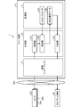
- FIG. 1 is a diagram showing a configuration example of the system 1 according to the first embodiment.
- the system 1 shown in FIG. 1 provides an image generation service that generates a three-dimensional skeleton model in which a three-dimensional skeleton obtained by markerless motion capture is modeled as computer graphics.
- such an image generation service can be used in various use cases such as production, analysis, and editing of computer graphics such as sports and games.
- the image captured by the camera 30 is referred to as an "captured image" from the aspect of distinguishing the image captured by the camera 30 from the skeleton image including the three-dimensional skeleton model which is computer graphics, that is, the label of the live-action image. May be described.
- the system 1 may include a server device 10, cameras 30A to 30N, and a client terminal 50.
- a server device 10 cameras 30A to 30N
- a client terminal 50 may be described as "camera 30".
- FIG. 1 shows an example in which one client terminal 50 is included in the system 1, a plurality of client terminals 50 may be included.
- the server device 10, the camera 30, and the client terminal 50 can be connected via an arbitrary network NW.
- the network NW may be any kind of communication network such as the Internet or LAN (Local Area Network) regardless of whether it is wired or wireless.
- FIG. 1 illustrates a case where the server device 10 provides a skeleton image including a three-dimensional skeleton model to the client terminal 50 via the network NW, but it is not necessarily bidirectional between the server device 10 and the client terminal 50. It does not matter if communication is not performed.
- the skeleton image does not necessarily have to go through the network NW, and may be provided from the server device 10 to the client terminal 50 via a broadcast wave.
- the server device 10 is a computer that provides the above-mentioned image generation service.
- the server device 10 can correspond to an example of an information processing device.
- the server device 10 can be implemented as package software or online software by installing an image generation program that realizes a function corresponding to the above image generation service on a desired computer.
- the server device 10 can be implemented as a server that provides the above-mentioned function related to the image generation service on-premises, for example, a Web server.
- the server device 10 may be implemented as a SaaS (Software as a Service) type application to provide the above image generation service as a cloud service.
- SaaS Software as a Service
- the camera 30 is an example of an image pickup device equipped with an image pickup device such as a CCD (Charge Coupled Device) or a CMOS (Complementary Metal Oxide Semiconductor).
- an image pickup device such as a CCD (Charge Coupled Device) or a CMOS (Complementary Metal Oxide Semiconductor).
- each camera is arranged so that the entire area of the three-dimensional space in which a competition such as a sport or a game for which computer graphics is generated is performed is within the shooting range of the plurality of cameras 30. 30 is installed. Further, from the aspect of estimating the three-dimensional skeleton of the subject existing in the three-dimensional space from the captured images captured by two or more cameras 30, each camera 30 is one of the shooting ranges with the other cameras 30. The parts can be arranged in an overlapping state. Under such an arrangement, a plurality of cameras 30 simultaneously image each frame, so that a plurality of images captured at the same timing for different viewpoints, that is, multi-viewpoint captured images can be obtained in frame units. .. As a matter of course, the frame rate at which each camera 30 captures an image is also unified to the same frame rate.
- the client terminal 50 corresponds to an example of a computer that receives a function corresponding to the above-mentioned image generation service.
- the client terminal 50 may be supported by a desktop computer such as a personal computer. This is just an example, and the client terminal 50 may be any computer such as a laptop computer, a mobile terminal device, or a wearable terminal.
- FIG. 1 shows an example in which the system 1 is constructed as a client-server system including the server device 10 and the client terminal 50, but the configuration example of the system 1 is not limited to this.
- the function corresponding to the above image generation service may be realized by a computer operating standalone.
- OpenPose Even so, in OpenPose, only two-dimensional posture detection is performed, so the posture of the skeletal part hidden by occlusion cannot be accurately detected. Therefore, OpenPose can only generate a skeletal model that lacks a three-dimensional effect.
- the server device 10 of the present disclosure estimates a three-dimensional skeleton from a multi-viewpoint captured image as part of the above-mentioned image generation service. As a result, the estimation of the skeleton part hidden by occlusion can be realized, and the three-dimensional skeleton estimation can be realized by the markerless motion capture. Then, the server device 10 of the present disclosure generates a three-dimensional skeleton model in which the three-dimensional skeleton thus estimated is modeled. Therefore, according to the server device 10 of the present disclosure, it is possible to generate a skeleton model having a three-dimensional effect.
- FIG. 1 schematically shows a block corresponding to a function included in the server device 10 among the devices included in the system 1.
- the server device 10 includes a communication interface 11, a storage unit 13, and a control unit 15.
- FIG. 1 only shows an excerpt of the functional parts related to the above image generation service, and the functional parts other than those shown in the figure, for example, the functional parts that the existing computer is equipped with by default or as options are servers. It does not prevent the device 10 from being provided.
- the communication interface 11 corresponds to an example of a communication control unit that controls communication with another device, for example, a camera 30 or a client terminal 50.
- a network interface card such as a LAN card can be adopted for the communication interface 11.
- the communication interface 11 notifies each camera 30 of an imaging start instruction and an imaging end instruction of the captured image, and receives the captured image from the camera 30.
- the communication interface 11 accepts various setting operations related to viewing the skeleton image from the client terminal 50, for example, setting an operation of the viewpoint of the camera including a virtual viewpoint, and outputs the skeleton image.
- the storage unit 13 can correspond to hardware that stores data used in various programs such as the above-mentioned image generation program, including an OS (Operating System) executed by the control unit 15.
- OS Operating System
- the storage unit 13 may correspond to the auxiliary storage device in the server device 10.
- HDD Hard Disk Drive
- optical disk SSD (Solid State Drive), etc.
- flash memory such as EPROM (Erasable Programmable Read Only Memory) can also be used as an auxiliary storage device.
- the storage unit 13 stores the camera parameter 13A and the three-dimensional skeleton data 13B as an example of the data used in the program executed by the control unit 15.
- the storage unit 13 can store various data such as the account information of the user of the client terminal 50 in addition to the captured images of each viewpoint.
- the camera parameter 13A is data related to the camera parameter.
- the camera parameter 13A may include external parameters such as the position and orientation of each camera 30 and internal parameters such as the angle of view of each camera 30 and lens distortion.
- the three-dimensional skeleton data 13B is data relating to the estimation result of the three-dimensional skeleton.
- the position of the joint held by the subject in the three-dimensional space for each frame of the captured image captured by the camera 30 is estimated by the estimation unit 15B described later.
- the three-dimensional skeleton data 13B may include time-series data of the positions of each joint in the three-dimensional space as an example.
- the three-dimensional skeleton data 13B may include the posture of each joint in the three-dimensional space, for example, the joint angle calculated based on the inverse kinematics, in addition to the position in the three-dimensional space.
- the control unit 15 is a processing unit that controls the entire server device 10.
- control unit 15 can be implemented by a hardware processor such as a CPU (Central Processing Unit) or an MPU (Micro Processing Unit).
- a CPU and an MPU are illustrated as an example of a processor, but it can be implemented by any processor regardless of a general-purpose type or a specialized type.
- control unit 15 may be realized by hard-wired logic such as ASIC (Application Specific Integrated Circuit) or FPGA (Field Programmable Gate Array).
- the control unit 15 virtually realizes the following processing unit by deploying the above image generation program on a work area of a RAM (Random Access Memory) mounted as a main storage device (not shown).
- FIG. 1 shows a functional unit corresponding to the above image generation program
- the program module corresponding to the above image generation program includes a functional unit corresponding to packaged software packaged with other functions. It doesn't matter.
- control unit 15 has an acquisition unit 15A, an estimation unit 15B, and a generation unit 15C.
- the acquisition unit 15A is a processing unit that acquires captured images of each viewpoint.
- the acquisition unit 15A can acquire captured images of each viewpoint transmitted from the cameras 30A to 30N in frame units.
- the information source from which the acquisition unit 15A acquires the captured image may be any information source, and is not limited to the camera 30.
- the acquisition unit 15A can acquire multi-viewpoint captured images from an auxiliary storage device such as a hard disk or optical disk that stores captured images of each viewpoint, or a removable medium such as a memory card or USB (Universal Serial Bus) memory. ..
- the acquisition unit 15A can also acquire captured images of each viewpoint from an external device other than the camera 5 via the network NW.
- the estimation unit 15B is a processing unit that estimates the three-dimensional skeleton based on the captured image of each viewpoint.
- the estimation unit 15B inputs an captured image to a model obtained by machine learning such as deep learning for each viewpoint of the camera 30, and thereby maps the certainty of the position on the captured image for each joint. Get the output of. Then, the estimation unit 15B estimates the position of each joint in the three-dimensional space by performing triangulation between the captured images based on the positions of the joints obtained for each captured image. Further, the estimation unit 15B can also calculate the posture of each joint in the three-dimensional space by calculating the joint angle based on the inverse kinematics using the position of each joint in the three-dimensional space. The positions and postures of the joints obtained for each frame of the captured image in the three-dimensional space are stored in the storage unit 13 as three-dimensional skeleton data.
- the generation unit 15C is a processing unit that generates a skeleton model in which a three-dimensional skeleton is modeled.
- the generation unit 15C renders a skeleton image at the viewpoints of the cameras 30A to 30N or at an arbitrary virtual viewpoint in the three-dimensional space.
- the generation unit 15C has 3 of the subject for each subject based on the position of the viewpoint where the user setting or the system setting is performed by the client terminal 50 or the like and the position of the joint included in the 3D skeleton data 13B. Render the skeleton model of the dimension.
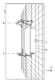
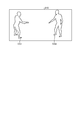
- FIG. 2 is a diagram showing an example of a skeleton image.
- FIG. 2 shows a skeleton image 200 generated from a captured image of a table tennis match.
- FIG. 2 shows a skeleton image 200 when the position of the central front surface in the longitudinal direction of the table tennis table is set to the virtual viewpoint Vc.
- the skeleton image 200 renders three-dimensional skeleton models M1 and M2 corresponding to two players playing a table tennis match.
- a three-dimensional model M3 corresponding to a table tennis table is rendered as an example of a three-dimensional model of an environment other than a person.
- the three-dimensional model M3 of the table tennis table does not necessarily have to be modeling data generated from the captured image.
- an environmental object such as the three-dimensional model M3 whose position and orientation do not change in the three-dimensional space may be modeling data created in advance.
- Such modeling data can be added to the skeleton image 200. In this way, since the three-dimensional skeleton model is rendered on the skeleton image 200, the expressive ability of the skeleton portion hidden by the occlusion is also improved.
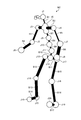
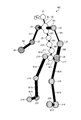
- FIG. 3 is a diagram showing an example of a three-dimensional skeleton model.
- FIG. 3 shows an enlarged view of the three-dimensional skeleton model M2 shown in FIG.
- the three-dimensional skeletal model M2 includes a head including feature points such as eyes and nose, as well as a clavicle, left and right shoulders, elbows, wrists, shoulders, elbows, wrists, hips, and knees. It includes joints J1 to J20 that can correspond to parts such as ankles and toes, and bones B1 to B17 that connect each joint.
- the joints J1 to J20 are modeled in a spherical shape, while the bones B1 to B17 are modeled in a linear or columnar shape.
- the size of the spheres of the joints J1 to J20 is set according to the distance between the virtual viewpoint Vc and the joints J1 to J20. For example, as the distance from the virtual viewpoint Vc decreases, in other words, the radius of the sphere of the joint is set larger as the joint is located closer to the front side. On the other hand, as the distance from the virtual viewpoint Vc increases, in other words, the radius of the sphere of the joint is set smaller as the joint is located closer to the back.
- joint J4, joint J7, and joint J8 as an example, the joints J8, joint J7, and joint J4 are arranged in ascending order of distance from the virtual viewpoint Vc. In this case, as shown in FIG. 3, the radius of the sphere of the joint J4, the joint J7 and the joint J8 is set so that J8> J7> J4.
- the thickness of the cylinder of the bone B1 to the bone B17 is set according to the virtual viewpoint Vc and the distance between the bone B1 and the bone B17.
- the radius of the bone cylinder is set larger as the bone is located closer to the front side.
- the radius of the cylinder of the bone is set smaller as the bone is located deeper.
- the ability to express the joints and bones in the anterior-posterior direction, that is, in the depth direction is improved.
- the viewpoint of the skeleton image is not necessarily limited to the virtual viewpoint given to the virtual camera, and may be any viewpoint of the camera 30A to the camera 30N. Further, the viewpoint of the skeleton image does not necessarily have to be fixed, and can be moved according to the trajectory of the user setting or GUI operation performed by the client terminal 50 or the like.
- the generation unit 15C can display the three-dimensional skeleton model in association with the captured image of each viewpoint as well as the captured image of the virtual viewpoint generated by using a plurality of captured images. For example, the generation unit 15C displays the skeleton image and the captured image corresponding to the same frame side by side on the left and right or vertically, or superimposes the skeleton image on the captured image by projecting the three-dimensional skeleton model onto the captured image. It can be displayed. When the three-dimensional skeleton model is projected onto the captured image in this way, the ability to express the twist of the joint can be improved by using the joint angle in addition to the position of each joint.
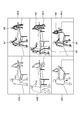
- FIG. 4 is a diagram showing an example of a method of associating a skeleton image and a captured image.
- the captured images 40A to 40C of the three viewpoints of the cameras 30A to 30C are displayed.
- the skeleton images of each viewpoint are superimposed on the captured images 40A to 40C. Images 40 ⁇ to 40 ⁇ are displayed.
- the skeleton image is superimposed on the captured image in this way, image processing that reduces the contrast ratio of the captured image, such as reduction of brightness and saturation, and increase of transparency, is performed from the aspect of increasing the contrast of the skeleton image as compared with the captured image.
- the superimposed images 40 ⁇ to 40 ⁇ can be generated after performing the above.
- Such display of the superimposed images 40 ⁇ to 40 ⁇ , and by extension, the aligned display of the captured images 40A to 40C and the superimposed images 40 ⁇ to 40 ⁇ can facilitate the comparison between the live-action image and the skeleton model.
- the 3D skeleton model When the 3D skeleton model is occlusioned by the 3D model of the environment, it is also possible to control whether or not to draw the part of the 3D skeleton model hidden by the 3D model of the environment. For example, when the legs of the 3D skeleton model M2 are hidden by the table tennis table as in the superimposed image 40 ⁇ , the legs of the 3D skeleton model M2 can be drawn to give a perspective effect, or the legs of the 3D skeleton model M2 can be drawn. By suppressing the drawing of the part, it is possible to suppress the occurrence of a sense of discomfort.
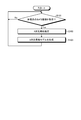
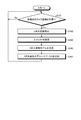
- FIG. 5 is a flowchart showing a procedure of image generation processing according to the first embodiment. As an example, this process can be continuously performed until the acquisition of the captured image from the camera 30 is completed.
- step S102 is waited until the captured image of each viewpoint is acquired by the acquisition unit 15A (step S101No). Then, when the captured image of each viewpoint is acquired by the acquisition unit 15A (step S101Yes), the estimation unit 15B estimates the three-dimensional skeleton based on the captured image of each viewpoint (step S102).
- step S103 the generation unit 15C generates a three-dimensional skeleton model in which the three-dimensional skeleton estimated in step S102 is modeled (step S103). After the process of step S103 is performed in this way, the process proceeds to the process of step S101.
- the server device 10 of the present disclosure estimates a three-dimensional skeleton from a multi-viewpoint captured image as part of the above-mentioned image generation service. As a result, it is possible to estimate the skeleton part hidden by occlusion and to realize three-dimensional skeleton estimation by markerless motion capture. Then, the server device 10 of the present disclosure generates a three-dimensional skeleton model in which the three-dimensional skeleton thus estimated is modeled. Therefore, according to the server device 10 of the present disclosure, it is possible to generate a skeleton model having a three-dimensional effect.
- Second embodiment >> Various effects can be added to the three-dimensional skeleton model described in the first embodiment above. Hereinafter, as the second embodiment, the contents of various effects and the setting method thereof will be illustrated.
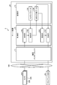
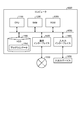
- FIG. 6 is a diagram showing a configuration example of the system according to the second embodiment. As shown in FIG. 6, the system 2 is different from the system 1 shown in FIG. 1 in that it has a server device 20 to which the function related to the above effect is added. Further, the server device 20 is different from the server device 10 shown in FIG. 1 in that the control unit 25 further has a setting unit 25A.
- the setting unit 25A is a processing unit that sets an effect on the three-dimensional skeleton model.
- the setting unit 25A can set the heat map effect on the skeletal parts such as joints and bones of the three-dimensional skeletal model.
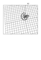
- FIG. 7 is a diagram showing an example of a heat map effect.
- FIG. 7 shows an example in which a heat map effect is added to the three-dimensional skeleton model M2 shown in FIG.
- heat maps of different colors are added to the joints included in the three-dimensional skeleton model M2 depending on the skeleton part. More specifically, the color of the heat map covering the joint is set separately according to the difference in the skeletal parts of the right arm, the left arm, the right leg and the left leg.
- the joints J3, J5, and joints J6 included in the right arm are provided with a first color, for example, a heat map corresponding to the hatching of the checkered pattern in the drawing.
- the joint J4, the joint J7, and the joint J8 included in the left arm are provided with a second color, that is, a heat map corresponding to the hatching of the points in the figure.
- the joints J13 to J16 included in the right leg are provided with a third color, that is, a heat map corresponding to the hatching of the diagonal line in the figure.
- the joints J17 to J20 included in the left leg are provided with a fourth color, that is, a heat map corresponding to the hatching of the vertical line in the figure.
- FIG. 7 shows an example in which the heat map effect is added to the joint, it goes without saying that the same effect can be added to the bone. Further, although FIG. 7 shows an example in which heat maps having different colors are set according to the position of the skeleton portion, heat maps having different areas may be set according to the position of the skeleton portion.
- the setting unit 25A can set an effect of highlighting the display color of the skeleton part such as the joint and the bone of the three-dimensional skeleton model.
- the setting unit 25A can set the effect of color change according to the movement of a skeletal part such as a joint or a bone.
- the setting unit 25A can use the amount of movement of the skeleton part.
- the setting unit 25A can calculate the amount of movement of the skeleton portion obtained from the position of the skeleton portion in the frame in which the skeleton image is being displayed and the position of the skeleton portion in the frame before the frame. For example, assuming that the skeleton image of the Nth frame is being displayed, the amount of movement of the skeleton portion from the N-1th frame to the Nth frame can be calculated.
- the setting unit 25A sets the saturation of the skeleton portion higher as the amount of movement increases, while setting the saturation of the skeleton portion lower as the amount of movement decreases. Further, the setting unit 25A can also set the color of the range corresponding to the movement amount of the skeleton portion among the colors assigned for each movement amount range as the display color of the skeleton portion. This makes it possible to realize an effect that distinguishes display colors according to the amount of movement.
- an example of calculating the amount of movement of the skeleton portion between adjacent frames has been given, but the intervals between the frames used for calculating the amount of movement do not necessarily have to be adjacent. For example, the amount of movement of the skeletal site can be calculated between a predetermined number of frames.
- the setting unit 25A can also set an effect of highlighting the skeleton part whose movement amount is equal to or larger than a predetermined threshold value among the skeleton parts included in the three-dimensional skeleton model. At this time, from the aspect of emphasizing the skeleton part having a large relative difference in movement between the skeleton parts, the setting unit 25A subtracts the movement amount of the center of gravity of the entire three-dimensional skeleton model from the movement amount of each skeleton part. It is possible to set an effect for highlighting a skeleton portion where the subtraction value of the movement amount is equal to or more than a predetermined threshold, for example, changing the display color or blinking.
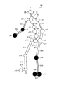
- FIG. 8 is a diagram showing an example of the highlighting effect.
- FIG. 8 highlights the skeletal parts whose subtraction value obtained by subtracting the movement amount of the center of gravity of the entire three-dimensional skeletal model M2 from the movement amount of the skeletal parts of joints J1 to J20 and bones B1 to B17 is equal to or more than the threshold value. The effect of is added.
- the display colors of the joints J5, joint J6, joint J18, joint J19 and joint J20 in which the subtraction value of the movement amount is equal to or more than the threshold value are the display colors of the other joints. Is set to a different display color.
- the display colors of the bones B3, B4, bone B16 and bone B17 whose movement amount subtraction value is equal to or more than the threshold value are set to different display colors from the display colors of the other bones. There is.
- the highlighting effect is set as compared with other parts. Therefore, it is possible to easily identify the skeletal part having a relatively large amount of movement. For example, in the case of table tennis, it is possible to support the evaluation and analysis of forms by identifying a skeletal part that moves rapidly in a scene where a racket is swung.
- the amount of movement of the skeletal part is given as an example, but the present invention is not limited to this.
- the velocity can be calculated for each skeleton part by calculating the change in the unit time, for example, the movement amount per frame from the movement amount in a predetermined number of frames.
- the acceleration can be calculated for each skeleton part by calculating the change in the unit time, for example, the speed per frame from the speed in a predetermined number of frames.
- the highlighting effect can be set according to the position of the skeleton part.
- an effect of changing the size of the joint sphere, the thickness of the bone cylinder, or the area of the heat map may be set.
- the size of the joint sphere corresponding to the skeletal part, the thickness of the bone column, or the area of the heat map is set larger as the amount of movement increases, and the skeletal part corresponds to the smaller the amount of movement.
- the size of the sphere of the joint to be used, the thickness of the bone column, or the area of the heat map can be set small.
- FIG. 9 is a flowchart showing the procedure of the image generation processing according to the second embodiment. As an example, this process can be continuously performed until the acquisition of the captured image from the camera 30 is completed.
- step S102 is waited until the captured image of each viewpoint is acquired by the acquisition unit 15A (step S101No). Then, when the captured image of each viewpoint is acquired by the acquisition unit 15A (step S101Yes), the estimation unit 15B estimates the three-dimensional skeleton based on the captured image of each viewpoint (step S102).
- the setting unit 25A sets the heat map effect and the highlighting effect based on the three-dimensional skeleton part and the amount of movement estimated in step S102 (step S201).
- step S103 the generation unit 15C generates a three-dimensional skeleton model in which the three-dimensional skeleton estimated in step S102 is modeled. Then, the generation unit 15C adds the effect set in step S201 to the three-dimensional skeleton model generated in step S103 (step S202). After the process of step S202 is performed in this way, the process proceeds to the process of step S101.
- the server device 20 of the present disclosure sets a heat map effect and a highlighting effect based on a three-dimensional skeleton portion and a movement amount as a part of the above image generation service. Therefore, according to the server device 20 of the present disclosure, it is possible to improve the visibility of the skeleton portion according to the purpose such as evaluation and analysis of the image.
- FIG. 10 is a diagram showing an example of a CG character model.
- the CG character model CG1 corresponding to the three-dimensional skeleton model M1 and the CG character model CG2 corresponding to the three-dimensional skeleton model M2 are rendered on the CG image 210.
- the server device 10 and the server device 20 identify an individual by executing an authentication process such as face recognition or iris recognition on a person included in the captured image. Then, the server device 10 and the server device 20 refer to the personal settings of the CG character model and the effect, and select the CG character model and the effect according to the personal settings corresponding to the individual identified as the result of the authentication process. be able to.
- the display of the heat map is used to identify the skeleton part, but the color or size of the heat map is changed according to the certainty of the estimation result of the three-dimensional skeleton at the skeleton part.
- the higher the certainty of the estimation result the more the color saturation of the heat map of the skeleton part can be increased, and the area of the heat map of the skeleton part can be increased.
- the lower the certainty of the estimation result the more the color saturation of the heat map of the skeleton portion can be reduced, and the area of the heat map of the skeleton portion can be reduced. This makes it possible to visualize the estimation accuracy of the 3D skeleton on the 3D skeleton model.
- FIG. 11 and 12 are diagrams showing an example of the locus of the position of the skeleton part.
- FIG. 11 shows the three captured images of the cameras 30A to 30C in the t ⁇ Nth frame before the nth frame from the tth frame in which the latest captured image was acquired by the acquisition unit 15A in the t ⁇ Nth frame.
- Superimposed images 60A to 60C on which the positions of the skeletal parts are superimposed are shown.
- the loci of the positions of the skeletal parts in the Nth frames from the tNth to the tth frames were superimposed on the three captured images of the cameras 30A to 30C in the tth frame.
- Superimposed images 80A-80C are shown. Further, in FIG.
- a superimposed image 80V in which the locus of the position of the skeleton portion in the Nth to Nth frames is superimposed on the captured image of the bird's-eye view (virtual viewpoint) in the tth frame is shown. It is shown. Further, in the superimposed images 80A to 80C shown in FIG. 11 and the superimposed images 80V shown in FIG. 12, the joints whose subtraction value obtained by subtracting the movement amount of the center of gravity of the entire three-dimensional skeleton model in the t-th frame is equal to or more than the threshold value are narrowed down. The loci of the joint positions in the N frames are superimposed, and for the other skeletal parts, only the positions of the skeletal parts in the t-th frame are superimposed.
- the joint spheres in the past frames other than the t-th frame are the joint spheres in the t-th frame.
- a radius smaller than the radius of the sphere is set. That is, for the same joint, the radius of the joint sphere in the t-th frame is set as the maximum value, and the radius of the joint sphere in the t-th frame is monotonically decreased as the t-th frame goes back to the past frame.
- the brightness and saturation can be monotonically decreased or the transparency can be monotonically increased as compared with the joints in the t-th frame as the t-th frame goes back to the past frame.
- the locus of the position of the skeleton portion can be visualized. Furthermore, since the radius of the sphere of the joint in the t-th frame is monotonically reduced from the t-th frame to the past frame, the time-series change in the position of the skeletal part becomes easier to identify.
- the example of generating the locus of the position of the joint is given here, it goes without saying that the locus of the position of the bone and the locus of the position of the heat map can be generated by the same method.
- each component of each device shown in the figure is a functional concept, and does not necessarily have to be physically configured as shown in the figure. That is, the specific form of distribution / integration of each device is not limited to the one shown in the figure, and all or part of the device is functionally or physically dispersed / physically distributed in arbitrary units according to various loads and usage conditions. Can be integrated and configured.
- FIG. 13 is a hardware configuration diagram showing an example of the computer 1000.
- the computer 1000 includes a CPU 1100, a RAM 1200, a ROM (Read Only Memory) 1300, an HDD (Hard Disk Drive) 1400, a communication interface 1500, and an input / output interface 1600.
- Each part of the computer 1000 is connected by a bus 1050.
- the CPU 1100 operates based on the program stored in the ROM 1300 or the HDD 1400, and controls each part. For example, the CPU 1100 expands the program stored in the ROM 1300 or the HDD 1400 into the RAM 1200 and executes processing corresponding to various programs.
- the ROM 1300 stores a boot program such as a BIOS (Basic Input Output System) executed by the CPU 1100 when the computer 1000 is started, a program that depends on the hardware of the computer 1000, and the like.
- BIOS Basic Input Output System
- the HDD 1400 is a computer-readable recording medium that non-temporarily records a program executed by the CPU 1100 and data used by the program.
- the HDD 1400 is a recording medium for recording the development support program according to the present disclosure, which is an example of the program data 1450.
- the communication interface 1500 is an interface for the computer 1000 to connect to an external network 1550 (for example, the Internet).
- the CPU 1100 receives data from another device or transmits data generated by the CPU 1100 to another device via the communication interface 1500.
- the input / output interface 1600 is an interface for connecting the input / output device 1650 and the computer 1000.
- the CPU 1100 receives data from an input device such as a keyboard or mouse via the input / output interface 1600. Further, the CPU 1100 transmits data to an output device such as a display, a speaker, or a printer via the input / output interface 1600. Further, the input / output interface 1600 may function as a media interface for reading a program or the like recorded on a predetermined recording medium (media).
- the media is, for example, an optical recording medium such as a DVD (Digital Versatile Disc) or PD (Phase change rewritable Disk), a magneto-optical recording medium such as an MO (Magneto-Optical disk), a tape medium, a magnetic recording medium, or a semiconductor memory.
- an optical recording medium such as a DVD (Digital Versatile Disc) or PD (Phase change rewritable Disk)
- a magneto-optical recording medium such as an MO (Magneto-Optical disk)
- a tape medium such as a magnetic tape
- magnetic recording medium such as a magnetic tape
- semiconductor memory for example, an optical recording medium such as a DVD (Digital Versatile Disc) or PD (Phase change rewritable Disk), a magneto-optical recording medium such as an MO (Magneto-Optical disk), a tape medium, a magnetic recording medium, or a semiconductor memory.
- the CPU 1100 of the computer 1000 is included in the control unit 15 by executing the image generation program loaded on the RAM 1200. Realize each functional part.
- the HDD 1400 stores the image generation program according to the present disclosure and the data in the content storage unit 121.
- the CPU 1100 reads the program data 1450 from the HDD 1400 and executes the program, but as another example, these programs may be acquired from another device via the external network 1550.
- the present technology can also have the following configurations.
- An estimation unit that estimates a three-dimensional skeleton based on captured images from multiple viewpoints, A generator that generates a skeleton model in which the three-dimensional skeleton is modeled, Information processing device equipped with.
- the generator models the joints of the three-dimensional skeleton in a spherical shape and the bones in a columnar shape.
- the generation unit sets the radius of the sphere of the joint or the radius of the cylinder of the bone based on the distance between the viewpoint or the virtual viewpoint of the plurality of viewpoints and the joint or the bone.
- the generator sets the radius of the sphere of the joint or the radius of the cylinder of the bone larger as the distance decreases, or the radius of the sphere of the joint or the bone as the distance increases. Set the radius of the cylinder small, The information processing device according to (3) above.
- the skeleton model is displayed in association with captured images of the plurality of viewpoints or virtual viewpoints.
- the skeleton model is displayed side by side or vertically or vertically with a captured image of the same frame as the skeleton model.
- the skeleton model is displayed superimposed on an image captured in the same frame as the skeleton model.
- the captured image is displayed with reduced brightness or saturation or increased transparency.
- a setting unit for setting an effect on the skeleton model is further provided.
- the setting unit sets the effect of the heat map covering the joint or the bone.
- (11) The setting unit sets a heat map of a different color or a different area depending on the position of the joint or the bone.
- (12) The setting unit sets heat maps of different colors or different areas according to the amount of movement, speed or acceleration of the joint or the skeletal part of the bone.
- the setting unit sets heat maps of different colors or different areas depending on the certainty of the estimation result of the three-dimensional skeleton at the skeletal part of the joint or the bone.
- the setting unit sets an effect of highlighting the joint or the skeletal part of the bone.
- the setting unit sets different display colors according to the amount of movement, speed, or acceleration of the joint or the skeletal part of the bone.
- (16) The setting unit sets an effect of highlighting a skeletal part of the joint or the bone whose movement amount, velocity or acceleration is equal to or higher than a predetermined threshold value.
- the setting unit sets an effect of highlighting a skeletal part whose subtraction value obtained by subtracting the movement amount of the center of gravity of the skeletal model from the movement amount of the skeletal part of the joint or the bone is equal to or more than a predetermined threshold value.
- the generation unit models the locus of the position of the joint or the skeletal part of the bone over a predetermined number of frames in the past from the latest frame in which the captured image is acquired.
- the generator sets the radius of the joint sphere or the radius of the bone cylinder in a past frame other than the latest frame smaller than the radius of the joint sphere or the radius of the bone cylinder in the latest frame.
- the information processing device maximizes the radius of the joint sphere or the radius of the bone cylinder in the latest frame, and the radius of the joint sphere in the latest frame or the radius of the joint sphere in the latest frame as it goes back from the latest frame to the past frame. Set the radius of the joint sphere of the past frame or the radius of the bone cylinder by monotonically reducing the radius of the bone cylinder, The information processing device according to (19) above.
- (21) Estimate a three-dimensional skeleton based on captured images from multiple viewpoints A skeleton model in which the three-dimensional skeleton is modeled is generated. An information processing method in which a computer executes processing.
- (22) Estimate a three-dimensional skeleton based on captured images from multiple viewpoints A skeleton model in which the three-dimensional skeleton is modeled is generated.
- An information processing program that causes a computer to perform processing.
- System 10 Server device 11 Communication interface 13 Storage unit 13A Camera parameter 13B 3D skeleton data 15 Control unit 15A Acquisition unit 15B Estimate unit 15C Generation unit 30A, 30B, 30N Camera 50 Client terminal
Landscapes
- Engineering & Computer Science (AREA)
- Physics & Mathematics (AREA)
- Theoretical Computer Science (AREA)
- General Physics & Mathematics (AREA)
- General Engineering & Computer Science (AREA)
- Geometry (AREA)
- Computer Vision & Pattern Recognition (AREA)
- Computer Graphics (AREA)
- Software Systems (AREA)
- Multimedia (AREA)
- Human Computer Interaction (AREA)
- Computer Hardware Design (AREA)
- Health & Medical Sciences (AREA)
- Biomedical Technology (AREA)
- Dermatology (AREA)
- General Health & Medical Sciences (AREA)
- Neurology (AREA)
- Neurosurgery (AREA)
- Architecture (AREA)
- Processing Or Creating Images (AREA)
Priority Applications (5)
| Application Number | Priority Date | Filing Date | Title |
|---|---|---|---|
| JP2021567205A JP7501543B2 (ja) | 2019-12-27 | 2020-12-10 | 情報処理装置、情報処理方法及び情報処理プログラム |
| EP20905020.2A EP4083926A4 (en) | 2019-12-27 | 2020-12-10 | INFORMATION PROCESSING DEVICE, INFORMATION PROCESSING METHOD AND INFORMATION PROCESSING PROGRAM |
| US17/777,416 US12067677B2 (en) | 2019-12-27 | 2020-12-10 | Information processing apparatus, information processing method, and computer-readable storage medium |
| CN202080088561.5A CN114830183A (zh) | 2019-12-27 | 2020-12-10 | 信息处理装置、信息处理方法和信息处理程序 |
| JP2024092499A JP7758104B2 (ja) | 2019-12-27 | 2024-06-06 | 情報処理装置、情報処理方法及び情報処理プログラム |
Applications Claiming Priority (2)
| Application Number | Priority Date | Filing Date | Title |
|---|---|---|---|
| JP2019-239053 | 2019-12-27 | ||
| JP2019239053 | 2019-12-27 |
Publications (1)
| Publication Number | Publication Date |
|---|---|
| WO2021131738A1 true WO2021131738A1 (ja) | 2021-07-01 |
Family
ID=76575470
Family Applications (1)
| Application Number | Title | Priority Date | Filing Date |
|---|---|---|---|
| PCT/JP2020/045994 Ceased WO2021131738A1 (ja) | 2019-12-27 | 2020-12-10 | 情報処理装置、情報処理方法及び情報処理プログラム |
Country Status (5)
| Country | Link |
|---|---|
| US (1) | US12067677B2 (enExample) |
| EP (1) | EP4083926A4 (enExample) |
| JP (2) | JP7501543B2 (enExample) |
| CN (1) | CN114830183A (enExample) |
| WO (1) | WO2021131738A1 (enExample) |
Cited By (4)
| Publication number | Priority date | Publication date | Assignee | Title |
|---|---|---|---|---|
| CN116503439A (zh) * | 2022-01-19 | 2023-07-28 | 华为技术有限公司 | 视频处理方法、视频播放方法及相关装置 |
| JP2023156940A (ja) * | 2022-04-13 | 2023-10-25 | キヤノン株式会社 | 画像処理装置、画像処理方法及びプログラム |
| JP7598986B1 (ja) | 2023-08-25 | 2024-12-12 | 株式会社バンダイ | 情報処理装置、及び、コンピュータプログラム |
| KR102907537B1 (ko) | 2023-08-25 | 2026-01-05 | 가부시키가이샤 반다이 | 정보 처리 장치 및 컴퓨터 프로그램 |
Families Citing this family (3)
| Publication number | Priority date | Publication date | Assignee | Title |
|---|---|---|---|---|
| WO2022149190A1 (ja) * | 2021-01-05 | 2022-07-14 | 富士通株式会社 | 骨格推定装置、骨格推定方法および体操採点支援システム |
| US20250046081A1 (en) * | 2021-09-17 | 2025-02-06 | Pingpod Inc. | System and method for generation and delivering of video clips of sport |
| JP2024130034A (ja) * | 2023-03-14 | 2024-09-30 | コニカミノルタ株式会社 | 機械学習モデル、プログラム、超音波診断装置、超音波診断システム、画像診断装置及び訓練装置 |
Citations (7)
| Publication number | Priority date | Publication date | Assignee | Title |
|---|---|---|---|---|
| JP2006148201A (ja) * | 2004-11-16 | 2006-06-08 | National Institute Of Advanced Industrial & Technology | 関節運動情報の電子透かし処理方法および装置 |
| JP2010017447A (ja) * | 2008-07-14 | 2010-01-28 | Nippon Telegr & Teleph Corp <Ntt> | 歩行動作分析装置、歩行動作分析方法、歩行動作分析プログラムおよびその記録媒体 |
| JP2010520561A (ja) * | 2007-03-07 | 2010-06-10 | モーテック・ビー.ブイ. | 人体における筋力と関節トルクとをリアルタイムでインタラクティブに視覚化する方法 |
| WO2012046392A1 (ja) * | 2010-10-08 | 2012-04-12 | パナソニック株式会社 | 姿勢推定装置及び姿勢推定方法 |
| JP2014068714A (ja) * | 2012-09-28 | 2014-04-21 | Kitasato Institute | 関節角度測定システム |
| JP2014228595A (ja) * | 2013-05-20 | 2014-12-08 | コニカミノルタ株式会社 | 拡張現実空間表示装置 |
| WO2019016152A1 (en) | 2017-07-19 | 2019-01-24 | Arlanxeo Deutschland Gmbh | STAR DIENIC RUBBER |
Family Cites Families (10)
| Publication number | Priority date | Publication date | Assignee | Title |
|---|---|---|---|---|
| WO2009061283A2 (en) * | 2007-11-09 | 2009-05-14 | National University Of Singapore | Human motion analysis system and method |
| US10664690B2 (en) | 2013-11-21 | 2020-05-26 | Mo' Motion Ventures | Jump shot and athletic activity analysis system |
| US10617474B2 (en) * | 2016-12-22 | 2020-04-14 | Episurf Ip-Management Ab | System and method for optimizing an implant position in an anatomical joint |
| EP3398551B1 (en) * | 2017-05-03 | 2024-10-30 | Stryker European Operations Holdings LLC | Methods of pose estimation of three-dimensional bone models in surgical planning a total ankle replacement |
| EP3651678A4 (en) * | 2017-07-08 | 2021-04-14 | Vuze Medical Ltd. | APPARATUS AND METHODS FOR USE IN IMAGE GUIDED SKELETON PROCEDURES |
| EP3655162A4 (en) | 2017-07-18 | 2021-04-21 | Molecular Devices, LLC | OBJECT RECORDING DEVICE WITH IMAGE-BASED LOCALIZATION OF THE PIPETTE TIP |
| US11648405B2 (en) * | 2019-11-01 | 2023-05-16 | Resolute 360, LLC | Percutaneous nerve evaluation for sacral neuromodulation |
| US11621086B2 (en) * | 2020-06-04 | 2023-04-04 | Episurf Ip-Management Ab | Customization of individualized implant |
| US12182956B2 (en) * | 2021-07-01 | 2024-12-31 | Microport Orthopedics Holdings Inc. | Systems and methods of using three-dimensional image reconstruction to aid in assessing bone or soft tissue aberrations for orthopedic surgery |
| US11983833B2 (en) * | 2022-03-30 | 2024-05-14 | Health Connect Global Limited | Computer-implemented method of generating an avatar |
-
2020
- 2020-12-10 EP EP20905020.2A patent/EP4083926A4/en active Pending
- 2020-12-10 CN CN202080088561.5A patent/CN114830183A/zh active Pending
- 2020-12-10 WO PCT/JP2020/045994 patent/WO2021131738A1/ja not_active Ceased
- 2020-12-10 JP JP2021567205A patent/JP7501543B2/ja active Active
- 2020-12-10 US US17/777,416 patent/US12067677B2/en active Active
-
2024
- 2024-06-06 JP JP2024092499A patent/JP7758104B2/ja active Active
Patent Citations (7)
| Publication number | Priority date | Publication date | Assignee | Title |
|---|---|---|---|---|
| JP2006148201A (ja) * | 2004-11-16 | 2006-06-08 | National Institute Of Advanced Industrial & Technology | 関節運動情報の電子透かし処理方法および装置 |
| JP2010520561A (ja) * | 2007-03-07 | 2010-06-10 | モーテック・ビー.ブイ. | 人体における筋力と関節トルクとをリアルタイムでインタラクティブに視覚化する方法 |
| JP2010017447A (ja) * | 2008-07-14 | 2010-01-28 | Nippon Telegr & Teleph Corp <Ntt> | 歩行動作分析装置、歩行動作分析方法、歩行動作分析プログラムおよびその記録媒体 |
| WO2012046392A1 (ja) * | 2010-10-08 | 2012-04-12 | パナソニック株式会社 | 姿勢推定装置及び姿勢推定方法 |
| JP2014068714A (ja) * | 2012-09-28 | 2014-04-21 | Kitasato Institute | 関節角度測定システム |
| JP2014228595A (ja) * | 2013-05-20 | 2014-12-08 | コニカミノルタ株式会社 | 拡張現実空間表示装置 |
| WO2019016152A1 (en) | 2017-07-19 | 2019-01-24 | Arlanxeo Deutschland Gmbh | STAR DIENIC RUBBER |
Non-Patent Citations (1)
| Title |
|---|
| See also references of EP4083926A4 |
Cited By (6)
| Publication number | Priority date | Publication date | Assignee | Title |
|---|---|---|---|---|
| CN116503439A (zh) * | 2022-01-19 | 2023-07-28 | 华为技术有限公司 | 视频处理方法、视频播放方法及相关装置 |
| EP4446985A4 (en) * | 2022-01-19 | 2025-04-16 | Huawei Technologies Co., Ltd. | Video processing method, video playing method and related apparatus |
| JP2023156940A (ja) * | 2022-04-13 | 2023-10-25 | キヤノン株式会社 | 画像処理装置、画像処理方法及びプログラム |
| JP7598986B1 (ja) | 2023-08-25 | 2024-12-12 | 株式会社バンダイ | 情報処理装置、及び、コンピュータプログラム |
| JP2025031263A (ja) * | 2023-08-25 | 2025-03-07 | 株式会社バンダイ | 情報処理装置、及び、コンピュータプログラム |
| KR102907537B1 (ko) | 2023-08-25 | 2026-01-05 | 가부시키가이샤 반다이 | 정보 처리 장치 및 컴퓨터 프로그램 |
Also Published As
| Publication number | Publication date |
|---|---|
| JP7501543B2 (ja) | 2024-06-18 |
| US12067677B2 (en) | 2024-08-20 |
| EP4083926A1 (en) | 2022-11-02 |
| EP4083926A4 (en) | 2023-07-05 |
| JP2024103791A (ja) | 2024-08-01 |
| CN114830183A (zh) | 2022-07-29 |
| JPWO2021131738A1 (enExample) | 2021-07-01 |
| JP7758104B2 (ja) | 2025-10-22 |
| US20240005600A1 (en) | 2024-01-04 |
Similar Documents
| Publication | Publication Date | Title |
|---|---|---|
| JP7501543B2 (ja) | 情報処理装置、情報処理方法及び情報処理プログラム | |
| JP7566973B2 (ja) | 情報処理装置、情報処理方法及びプログラム | |
| US11948376B2 (en) | Method, system, and device of generating a reduced-size volumetric dataset | |
| CN111199579B (zh) | 一种目标物的三维模型构建方法、装置、设备及介质 | |
| US8737767B2 (en) | Perceptually guided capture and stylization of 3D human figures | |
| JP6934887B2 (ja) | 単眼カメラを用いたリアルタイム3d捕捉およびライブフィードバックのための方法およびシステム | |
| JP4473754B2 (ja) | 仮想試着装置 | |
| JP5773944B2 (ja) | 情報処理装置および情報処理方法 | |
| US10229483B2 (en) | Image processing apparatus and image processing method for setting an illumination environment | |
| Tian et al. | Handling occlusions in augmented reality based on 3D reconstruction method | |
| JP6793151B2 (ja) | オブジェクトトラッキング装置、オブジェクトトラッキング方法およびオブジェクトトラッキングプログラム | |
| US20250278843A1 (en) | Training multi-object tracking models using simulation | |
| JP7164045B2 (ja) | 骨格認識方法、骨格認識プログラムおよび骨格認識システム | |
| JP7164968B2 (ja) | 画像処理装置、画像処理装置の制御方法及びプログラム | |
| CN110969706B (zh) | 增强现实设备及其图像处理方法、系统以及存储介质 | |
| JP2018206025A (ja) | 情報処理装置、情報処理方法 | |
| JP2012185772A (ja) | 非固定ズームカメラを用いた自由視点映像の合成画質高精度化方法およびプログラム | |
| JP6319804B2 (ja) | 投影画像生成装置、投影画像生成方法および投影画像生成プログラム | |
| JP7318814B2 (ja) | データ生成方法、データ生成プログラムおよび情報処理装置 | |
| US11501577B2 (en) | Information processing apparatus, information processing method, and storage medium for determining a contact between objects | |
| WO2023058545A1 (ja) | 情報処理装置および方法、プログラム | |
| JP2019057070A (ja) | 画像処理装置、画像処理方法、およびプログラム | |
| Amirkhanov et al. | WithTeeth: Denture Preview in Augmented Reality. | |
| JP2025523804A (ja) | コンピュータ生成イメージをアニメーション化するための方法及びアプリケーション | |
| JP7500333B2 (ja) | 生成装置、生成方法、およびプログラム |
Legal Events
| Date | Code | Title | Description |
|---|---|---|---|
| 121 | Ep: the epo has been informed by wipo that ep was designated in this application |
Ref document number: 20905020 Country of ref document: EP Kind code of ref document: A1 |
|
| WWE | Wipo information: entry into national phase |
Ref document number: 17777416 Country of ref document: US |
|
| ENP | Entry into the national phase |
Ref document number: 2021567205 Country of ref document: JP Kind code of ref document: A |
|
| NENP | Non-entry into the national phase |
Ref country code: DE |
|
| ENP | Entry into the national phase |
Ref document number: 2020905020 Country of ref document: EP Effective date: 20220727 |