WO2021125103A1 - バルーンカテーテル - Google Patents
バルーンカテーテル Download PDFInfo
- Publication number
- WO2021125103A1 WO2021125103A1 PCT/JP2020/046382 JP2020046382W WO2021125103A1 WO 2021125103 A1 WO2021125103 A1 WO 2021125103A1 JP 2020046382 W JP2020046382 W JP 2020046382W WO 2021125103 A1 WO2021125103 A1 WO 2021125103A1
- Authority
- WO
- WIPO (PCT)
- Prior art keywords
- lumen
- balloon catheter
- shaft
- long body
- balloon
- Prior art date
- Legal status (The legal status is an assumption and is not a legal conclusion. Google has not performed a legal analysis and makes no representation as to the accuracy of the status listed.)
- Ceased
Links
Images







Classifications
-
- A—HUMAN NECESSITIES
- A61—MEDICAL OR VETERINARY SCIENCE; HYGIENE
- A61M—DEVICES FOR INTRODUCING MEDIA INTO, OR ONTO, THE BODY; DEVICES FOR TRANSDUCING BODY MEDIA OR FOR TAKING MEDIA FROM THE BODY; DEVICES FOR PRODUCING OR ENDING SLEEP OR STUPOR
- A61M25/00—Catheters; Hollow probes
- A61M25/10—Balloon catheters
- A61M25/104—Balloon catheters used for angioplasty
-
- A—HUMAN NECESSITIES
- A61—MEDICAL OR VETERINARY SCIENCE; HYGIENE
- A61B—DIAGNOSIS; SURGERY; IDENTIFICATION
- A61B17/00—Surgical instruments, devices or methods
- A61B17/32—Surgical cutting instruments
- A61B17/3205—Excision instruments
- A61B17/3207—Atherectomy devices working by cutting or abrading; Similar devices specially adapted for non-vascular obstructions
- A61B17/320725—Atherectomy devices working by cutting or abrading; Similar devices specially adapted for non-vascular obstructions with radially expandable cutting or abrading elements
-
- A—HUMAN NECESSITIES
- A61—MEDICAL OR VETERINARY SCIENCE; HYGIENE
- A61M—DEVICES FOR INTRODUCING MEDIA INTO, OR ONTO, THE BODY; DEVICES FOR TRANSDUCING BODY MEDIA OR FOR TAKING MEDIA FROM THE BODY; DEVICES FOR PRODUCING OR ENDING SLEEP OR STUPOR
- A61M25/00—Catheters; Hollow probes
- A61M25/0021—Catheters; Hollow probes characterised by the form of the tubing
- A61M25/0023—Catheters; Hollow probes characterised by the form of the tubing by the form of the lumen, e.g. cross-section, variable diameter
- A61M25/0026—Multi-lumen catheters with stationary elements
- A61M2025/0037—Multi-lumen catheters with stationary elements characterized by lumina being arranged side-by-side
-
- A—HUMAN NECESSITIES
- A61—MEDICAL OR VETERINARY SCIENCE; HYGIENE
- A61M—DEVICES FOR INTRODUCING MEDIA INTO, OR ONTO, THE BODY; DEVICES FOR TRANSDUCING BODY MEDIA OR FOR TAKING MEDIA FROM THE BODY; DEVICES FOR PRODUCING OR ENDING SLEEP OR STUPOR
- A61M25/00—Catheters; Hollow probes
- A61M25/10—Balloon catheters
- A61M2025/1043—Balloon catheters with special features or adapted for special applications
- A61M2025/1086—Balloon catheters with special features or adapted for special applications having a special balloon surface topography, e.g. pores, protuberances, spikes or grooves
-
- A—HUMAN NECESSITIES
- A61—MEDICAL OR VETERINARY SCIENCE; HYGIENE
- A61M—DEVICES FOR INTRODUCING MEDIA INTO, OR ONTO, THE BODY; DEVICES FOR TRANSDUCING BODY MEDIA OR FOR TAKING MEDIA FROM THE BODY; DEVICES FOR PRODUCING OR ENDING SLEEP OR STUPOR
- A61M25/00—Catheters; Hollow probes
- A61M25/10—Balloon catheters
- A61M2025/1043—Balloon catheters with special features or adapted for special applications
- A61M2025/109—Balloon catheters with special features or adapted for special applications having balloons for removing solid matters, e.g. by grasping or scraping plaque, thrombus or other matters that obstruct the flow
-
- A—HUMAN NECESSITIES
- A61—MEDICAL OR VETERINARY SCIENCE; HYGIENE
- A61M—DEVICES FOR INTRODUCING MEDIA INTO, OR ONTO, THE BODY; DEVICES FOR TRANSDUCING BODY MEDIA OR FOR TAKING MEDIA FROM THE BODY; DEVICES FOR PRODUCING OR ENDING SLEEP OR STUPOR
- A61M25/00—Catheters; Hollow probes
- A61M25/10—Balloon catheters
- A61M2025/1043—Balloon catheters with special features or adapted for special applications
- A61M2025/1093—Balloon catheters with special features or adapted for special applications having particular tip characteristics
Definitions
- the present invention relates to a balloon catheter having a long body.
- stenosis occurs in blood vessels, which are the flow paths for blood circulation in the body, and various diseases occur due to the stagnation of blood circulation.
- stenosis of the coronary arteries that supply blood to the heart may lead to serious diseases such as angina pectoris and myocardial infarction.
- a procedure for dilating the stenotic part using a balloon catheter such as angioplasty such as percutaneous angioplasty (PTA) or percutaneous coronary angioplasty (PTCA).
- PTA percutaneous angioplasty
- PTCA percutaneous coronary angioplasty
- Angioplasty is a minimally invasive therapy that does not require thoracotomy, such as bypass surgery, and is widely practiced.
- a stenosis hardened due to calcification or the like may be formed on the inner wall of the blood vessel.
- a calcified lesion it is difficult to dilate the hardened stenosis with a general balloon catheter.
- a method of dilating the stenosis by placing an indwelling dilation device called a stent in the stenosis of the blood vessel is also used.
- ISR In-Stent-Restenosis
- the neointima is soft and the surface is slippery, so with a general balloon catheter, the position of the balloon may shift from the lesion when the balloon is expanded, and the blood vessel may be damaged.
- a balloon catheter capable of expanding the stenosis even in such a calcified lesion or an ISR lesion
- a balloon catheter in which the balloon has a scoring element.
- a scoring element is a member used to fix a balloon to the inner wall of a blood vessel, crack a calcified site on the inner wall of a blood vessel, or remove the calcified site to eliminate stenosis. It has a blade-like part for fixing and cutting.
- Patent Documents 1 and 2 there are those listed in Patent Documents 1 and 2. Further, in order to protect the incision element when the balloon to which the incision element is attached is conveyed to the treatment site, it has a balloon catheter having a sheath attached to the balloon (Patent Document 3) and a cavity through which a cutting device is passed. A balloon catheter (Patent Document 4) is disclosed.
- the scoring element Since the scoring element needs to act on the calcified hard lesion, it is usually formed of a material having high rigidity such as metal. Therefore, if the balloon is inserted into the blood vessel with the scoring element fixed to the balloon from the beginning, the passage of the balloon in the blood vessel may be deteriorated due to the rigidity of the scoring element. Therefore, a method may be adopted in which a long scoring element is delivered to the lesion after the balloon is inserted into the blood vessel in a contracted state. At this time, in order to fix the blade-shaped portion of the scoring element to the blood vessel wall or excise the lesion portion by the blade-shaped portion, it is necessary to bring the blade-shaped portion into contact with the blood vessel wall at a desired angle. However, with conventional balloon catheters, the scoring element rotates around the axis during delivery, and the scoring element shifts in the circumferential direction of the balloon during delivery. There was a problem that it could not be brought into contact with the lesion on the inner wall.
- An object of the present invention is to provide a balloon catheter capable of bringing a long body into contact with a lesion at a desired angle.
- a balloon catheter comprising a shaft extending in the perspective direction and a balloon provided on the distal side of the shaft. It has a long body extending in the perspective direction along the shaft and having a living tissue contact portion at the distal end, and a lumen for a long body through which the long body can be inserted. And The lumen for a long body has a first engaging portion that is engaged with the long body so that the axial rotation angle of the long body is 0 degrees or more and 60 degrees or less.
- a balloon catheter characterized in that the first engaging portion is arranged between the distal end of the long body lumen and a point 30 cm proximal to the distal end.
- the first balloon catheter according to the present invention preferably includes the following configurations [2] to [16].
- [2] The balloon catheter according to [1], wherein in the first engaging portion, the elongated body can rotate around the axis in a range of 5 degrees or more and 60 degrees or less.
- [3] The balloon catheter according to [1] or [2], wherein the biological tissue contact portion is arranged on the radial outer side of the shaft in the first engaging portion.
- the cross-sectional shape of the long body perpendicular to the perspective direction and the cross-sectional shape of the long body lumen in the first engaging portion are non-circular. Balloon catheter.
- the elongated body has a portion having a non-circular cross-sectional shape perpendicular to the perspective direction on the distal side of the first engaging portion, and the elongated body lumen has the first
- the balloon catheter according to any one of [1] to [4] which has a portion having a circular cross-sectional shape perpendicular to the perspective direction on the proximal side of the engaging portion.
- the cross-sectional shape of the long body lumen perpendicular to the perspective direction continuously changes in the section from the point proximal to the first engaging portion to the first engaging portion in the perspective direction.
- the balloon catheter according to any one of [1] to [6].
- the shaft has an inner surface facing inward in the radial direction of the shaft and an outer surface facing the outer side, and the lumen for a long body has the inner surface and the outer surface of the shaft.
- the balloon catheter according to any one of [1] to [8] formed between the two.
- the balloon has an expansion portion that is not fixed to the shaft, and a fixing portion that is arranged on the distal side and the proximal side of the expansion portion and is connected to the shaft.
- the balloon has an expansion portion that is not fixed to the shaft and a fixing portion that is arranged on the distal side and the proximal side of the expansion portion and is connected to the shaft.
- the expansion portion includes a straight pipe portion, a proximal taper portion arranged on the proximal side of the straight pipe portion, and a distal taper portion arranged on the distal side of the straight pipe portion.
- the balloon catheter according to any one of [1] to [11], wherein the distal end of the long body lumen is arranged in the proximal taper portion.
- the balloon has an expansion portion that is not fixed to the shaft and a fixing portion that is arranged on the distal side and the proximal side of the expansion portion and is connected to the shaft.
- the expansion portion includes a straight pipe portion, a proximal taper portion arranged on the proximal side of the straight pipe portion, and a distal taper portion arranged on the distal side of the straight pipe portion.
- the balloon catheter according to any one of [1] to [14], wherein the distal end of the elongated body has a tapered shape.
- the present invention further provides a second balloon catheter, and one embodiment of the second balloon catheter comprises the following configuration.
- a balloon catheter having a shaft extending in the perspective direction and a balloon provided on the distal side of the shaft. It has a long body extending in the perspective direction along the shaft and the balloon, and a lumen extending in the perspective direction along the shaft and the balloon and allowing the long body to be inserted. And The proximal end of the lumen is located proximal to the shaft with an insertion slot for the elongated body.
- the balloon is arranged on the extension portion not fixed to the shaft, the proximal side fixing portion arranged on the proximal side of the expansion portion and connected to the shaft, and the distal side of the expansion portion.
- the lumen has a distal side fixing part that is connected to the shaft, and the lumen has an opening that extends radially outward in the extension part and extends in the perspective direction.
- the proximal end of the opening is located distal to the proximal end of the extension.
- the lumen has no openings distal to the proximal end of the lumen and proximal to the proximal end of the opening.
- the lumen has a second engaging portion engaged with the elongated body at least a part of the opening so that the elongated body does not rotate by 60 degrees or more in the rotation direction about the perspective direction.
- a balloon catheter characterized in that, in the second engaging portion, the width of the lumen at the opening is smaller than the width of the lumen at half the depth of the lumen.
- the second balloon catheter according to the present invention preferably includes the following configurations [18] to [29].
- [18] The balloon catheter according to [17], wherein in the second engaging portion, the elongated body can rotate around the axis in a range of 5 degrees or more and 60 degrees or less.
- the cross-sectional shape of the lumen perpendicular to the perspective direction continuously changes in the section from the point proximal to the second engaging portion to the second engaging portion in the perspective direction [].
- the expansion portion includes a straight pipe portion, a proximal side taper portion arranged on the proximal side of the straight pipe portion, and a distal side taper arranged on the distal side of the straight pipe portion.
- the expansion portion includes a straight pipe portion, a proximal side taper portion arranged on the proximal side of the straight pipe portion, and a distal side taper arranged on the distal side of the straight pipe portion.
- the elongated body has a biological tissue contact portion, and in the second engaging portion, a portion of the elongated body other than the biological tissue contact portion is engaged with the lumen [17]. ] To [24]. [26] The elongated body has a living tissue contact portion, and the living tissue contact portion is arranged outside the opening in the radial direction of the expansion portion [17] to [25].
- the balloon catheter according to any. [27] The lumen has a stopper on the distal end of the opening at the same position as the distal end of the elongated body or on the distal side of the distal end of the elongated body. The balloon catheter according to any one of [17] to [26].
- the above-mentioned configuration suppresses the axial rotation of the long body at the time of delivery and the displacement in the circumferential direction on the balloon while improving the passage of the balloon in the blood vessel, and lengthens the balloon.
- the scale can be brought into contact with the lesion at the desired angle. This makes it possible to appropriately fix the long body to the lesion and to appropriately excise the lesion with the long body.
- FIG. 1 The whole view of the 1st balloon catheter which concerns on one Embodiment of this invention is shown.
- the II-II cross-sectional view of the first balloon catheter shown in FIG. 1 is shown.
- FIG. 2 shows an enlarged cross-sectional view of a lumen portion for a long body of the first balloon catheter shown in FIG.
- a cross-sectional view of a long body according to an embodiment of the present invention is shown.
- a cross-sectional view of a long body according to another embodiment of the present invention is shown.
- a cross-sectional view of a first balloon catheter according to an embodiment of the present invention is shown.
- the VII-VII cross-sectional view of the first balloon catheter shown in FIG. 1 is shown.
- the side view of the area R of the 1st balloon catheter which concerns on one Embodiment of this invention is shown.
- a side view of a region R of a first balloon catheter according to another embodiment of the present invention is shown.
- a side view of a region R of a first balloon catheter according to still another embodiment of the present invention is shown.
- a cross-sectional view showing another example of the II-II cross-sectional view of the first balloon catheter shown in FIG. 1 is shown.
- a cross-sectional view showing still another example of the II-II cross-sectional view of the first balloon catheter shown in FIG. 1 is shown.
- the whole view of the 2nd balloon catheter which concerns on one Embodiment of this invention is shown.
- the XV-XV cross-sectional view of the second balloon catheter shown in FIG. 14 is shown.
- a plan view of the distal portion of the second balloon catheter according to another embodiment of the present invention as viewed from the lumen side is shown.
- the XVII-XVII cross-sectional view of the second balloon catheter shown in FIG. 16 is shown.
- the XVIII-XVIII cross-sectional view of the second balloon catheter shown in FIG. 13 is shown.
- the XIX-XIX sectional view of the second balloon catheter shown in FIG. 14 is shown.
- a cross-sectional view showing another example of the XIX-XIX cross-sectional view of the second balloon catheter shown in FIG. 14 is shown.
- FIG. 14 shows a cross-sectional view of the second balloon catheter shown in FIG. 14 XXII-XXII.
- a modified example of the XXII-XXII cross-sectional view of the second balloon catheter shown in FIG. 14 is shown.
- a cross-sectional view of the second balloon catheter shown in FIG. 22 when the elongated body is not inserted is shown.
- An enlarged view of the lumen portion of the cross-sectional view shown in FIG. 22 is shown.
- An enlarged view of the lumen portion of the cross-sectional view shown in FIG. 24 is shown.
- a perspective sectional view of a distal portion of a second balloon catheter according to another embodiment of the present invention is shown.
- a perspective sectional view of a distal portion of a second balloon catheter according to still another embodiment of the present invention is shown.
- the XXIX-XXIX cross-sectional view of the second balloon catheter shown in FIG. 27 is shown.
- a modified example of the XXIX-XXIX cross-sectional view of the second balloon catheter shown in FIG. 27 is shown.
- a cross-sectional view of the second balloon catheter shown in FIG. 29 when the elongated body is not inserted is shown.
- FIG. 27 shows a cross-sectional view of the second balloon catheter shown in FIG. 27.
- the perspective view of the long body which concerns on one Embodiment of this invention is shown.
- a perspective view of a long body according to another embodiment of the present invention is shown.
- the first balloon catheter includes a shaft extending in the perspective direction and a balloon provided on the distal side of the shaft in the perspective direction along the shaft. It has a long body that extends and has a living tissue contact part at the distal end, and a long body lumen through which the long body can be inserted.
- the first engaging portion is engaged with the elongated body so that the axis rotation angle of the elongated body is 0 degrees or more and 60 degrees or less, and the first engaging portion is for the elongated body. It is located between the distal end of the lumen and a point 30 cm proximal to the distal end.
- the lumen for a long body has a first engaging portion engaged with the long body in the above range so as to prevent the shaft rotation of the long body, the shaft of the long body is formed. It is possible to prevent the rotation in the direction and the displacement in the circumferential direction on the balloon so that the long body is brought into contact with the lesion at the desired angle.
- FIG. 1 shows an overall view of a first balloon catheter 100 according to an embodiment of the present invention.
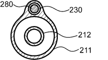
- FIG. 2 shows a cross-sectional view of II-II of the first balloon catheter 100 shown in FIG. 1, and shows a cross-sectional view of the first engaging portion 131 perpendicular to the perspective direction.
- FIG. 3 shows an enlarged cross-sectional view of a lumen portion for a long body of the first balloon catheter 100 shown in FIG.
- FIG. 4 is a cross-sectional view perpendicular to the perspective direction of the long body according to one embodiment of the present invention, and FIG.
- FIG. 5 is a cross-sectional view perpendicular to the perspective direction of the long body according to another embodiment of the present invention.
- FIG. 6 shows a cross-sectional view of the first balloon catheter 100 according to an embodiment of the present invention
- FIG. 7 shows a VII-VII cross-sectional view of the first balloon catheter 100 shown in FIG. 8 to 10 show side views of the region R of the first balloon catheter 100 according to different embodiments.
- 11 and 12 represent another example of the II-II cross-sectional view of the first balloon catheter 100 shown in FIG. 1 according to different embodiments.
- the first balloon catheter 100 includes a shaft 110 extending in the perspective direction and a balloon 120 provided on the distal side of the shaft 110.
- a long body 180 extending in the perspective direction along the shaft 110 and having a biological tissue contact portion 181 at the distal end, and a long body lumen 130 through which the long body 180 can be inserted.
- the lumen 130 for a long body has a first engaging portion 131 that is engaged with the long body 180 so that the angle of axial rotation of the long body 180 is 0 degrees or more and 60 degrees or less.
- the first engaging portion 131 is arranged between the distal end 130d of the long body lumen 130 and a point 30 cm proximal to the distal end 130d.
- the elongated body 180 is exposed from the distal end 130d of the lumen 130 for the elongated body and is arranged along the balloon 120. However, when the first engaging portion 131 is arranged in the above range, the elongated body 180 is arranged. Rotation is prevented, and the long body 180 exposed from the distal end 130d of the long body lumen 130 is less likely to shift in the circumferential direction on the balloon 120, so that the long body 180 is lesioned at a desired angle. It can be brought into contact with the portion.
- the distal side refers to the direction of the person to be treated with respect to the extending direction of the shaft 110
- the proximal side is used with respect to the opposite side of the distal side, that is, the extending direction of the shaft 110. It points in the direction of the person's hand.
- the direction from the proximal side to the distal side of the shaft 110 and the direction from the distal side to the proximal side are referred to as a perspective direction.
- the distance D is the distance between the distal end 130d of the long body lumen 130 and the point where the first engaging portion 131 is arranged, the distance D is 0 cm or more and 30 cm or less. That is, the first engaging portion 131 may be arranged at the distal end 130d of the long body lumen 130, or at a point 30 cm proximal to the distal end 130d of the long body lumen 130. It suffices if it is placed somewhere in. Further, the first engaging portion 131 may be continuously provided between the distal end 130d and a point 30 cm proximal to the distal end 130d, or may be provided in plurality or a single portion at a distance. It may have been.
- the lower limit of the distance D is 0 cm
- the upper limit of the distance D is 30 cm
- the upper limit of the distance D is preferably 25 cm, 20 cm, 15 cm, 10 cm, 5 cm, 3 cm, and may be 1 cm or less.
- the elongated body 180 has a living tissue contact portion 181 at the distal end portion that acts on the living body.
- the biological tissue contact portion 181 can act on the lesion portion to fix the balloon 120 to the lesion portion, and the biological tissue contact portion 181 can excise the stenotic portion or the like occurring in the lesion portion.
- the living tissue contact portion 181 may have an arbitrary shape, but it is preferable that the living tissue contact portion 181 has, for example, a blade shape.
- the blade shape is a cross-sectional shape of the oblong body 180 perpendicular to the perspective, polygonal shape such as a triangle or parallelogram, fan shape, wedge shape, convex shape, spindle shape, star shape, or any combination thereof. It can be provided by combining the above shapes into a shape or a circle and processing a part of each figure into a blade shape.
- FIG. 4 shows a cross-sectional view of a long body 180 in which the cross-sectional shape is substantially fan-shaped and the portion forming the central angle is processed as a blade-shaped portion, and FIG.
- the biological tissue contact portion 181 showing the cross-sectional view of the elongated body 180 processed as described above may be provided at the distal end of the elongated body 180 acting on the lesion portion, and the lesion of the elongated body 180 may be provided.
- the living tissue contact portion 181 may not be provided in a portion other than the distal end portion that acts on the portion.
- the cross-sectional shape of the elongated body 180 that is perpendicular to the perspective direction of the portion where the living tissue contact portion 181 is not provided shall be, for example, a circular shape, an elliptical shape, a polygonal shape, a shape obtained by combining these, or any other shape. However, it is preferably circular.
- the term "circle” does not mean only a perfect circle, but includes all circular shapes. If the cross-sectional shape of the long body 180 perpendicular to the perspective direction is circular in the portion where the biological tissue contact portion 181 is not provided, the long body 180 can be easily inserted into the long body lumen 130.
- the distal end of the elongated body 180 has a tapered shape. If the distal end of the elongated body 180 has a tapered shape, the elongated body 180 can be easily inserted into the lumen 130 for the elongated body.
- the major axis d of the cross section of the elongated body 180 perpendicular to the perspective direction is preferably 0.1 mm or more, more preferably 0.15 mm or more, and further preferably 0.2 mm or more.
- the major axis d of the long body 180 is preferably 1 mm or less, more preferably 0.9 mm or less, and even more preferably 0.8 mm or less.
- the major axis d of the elongated body 180 is the diameter of a virtual circle inscribed by a cross section perpendicular to the perspective direction of the elongated body 180, and is a cross section perpendicular to the perspective direction of the elongated body 180. If is circular, it is the diameter of the circle.
- the elongated body 180 has a portion where the living tissue contact portion 181 is provided and a portion where the living tissue contact portion 181 is not provided, and the cross-sectional shape perpendicular to the perspective direction differs depending on the location in the perspective direction. Therefore, the major axis d may be different in the perspective direction, but it is preferable that the major axis d is within the above range in any cross section.
- Examples of the material constituting the elongated body 180 include metals such as stainless steel, titanium, nickel-titanium alloy, cobalt-chromium alloy, and tungsten alloy; polyarylate fiber, aramid fiber, ultrahigh molecular weight polyethylene fiber, PBO fiber, and carbon fiber. Fiber materials made of synthetic resins such as, and ceramics made of alumina, zirconia, barium titanate, etc. can be mentioned. Only one type of these may be used, two or more types may be used in combination, and the fiber material may be monofilament or multifilament.
- only one lumen 130 for a long body may be provided, or a plurality of lumens 130 (not shown) may be provided.
- the number of lumens 130 for a long body is 1 or more, may be 2 or more, and may be 3 or more.
- the number of lumens 130 for a long body is preferably 6 or less, more preferably 5 or less, and even more preferably 4 or less.
- a plurality of long bodies 180 can be inserted and effectively fixed or excised without deteriorating the intravascular insertability of the first balloon catheter 100. It becomes possible to take measures such as.
- the cross-sectional shape of the lumen 130 for a long body may be any shape as long as the long body 180 can be inserted, for example, a circular shape, an elliptical shape, a polygonal shape, or a polygonal shape. Alternatively, the shape may be a combination of these or any other shape, but a circular shape is preferable. If the cross-sectional shape of the lumen 130 for a long body perpendicular to the perspective direction is circular, it becomes easy to insert the long body 180.
- the term "circular” does not mean only a perfect circle as described above, but includes all circular shapes.
- the major axis of the cross section of the long body lumen 130 perpendicular to the perspective direction is preferably 0.2 mm or more, more preferably 0.3 mm or more, still more preferably 0.5 mm or more.
- the major axis of the cross section of the long body lumen 130 perpendicular to the perspective direction is preferably 1.2 mm or less, more preferably 1 mm or less, and further preferably 0.8 mm or less.
- the balloon 120 can be delivered to the lesion portion without deteriorating the insertability of the first balloon catheter 100.
- the major axis of the cross section of the long body lumen 130 perpendicular to the perspective is the same as the major axis d of the elongated body 180, which is a virtual circle inscribed by the cross section of the elongated body lumen 130 perpendicular to the perspective. It is the diameter, and if the cross section of the long body lumen 130 perpendicular to the perspective direction is circular, it is the diameter of the circle.
- the cross-sectional shape perpendicular to the perspective direction may differ depending on the location in the perspective direction, and the major axis of the cross section may differ, but any cross section may be used.
- the major axis is preferably within the above range.
- the long body 180 is slidable in the lumen 130 for the long body. If the long body 180 is slidable in the long body lumen 130, the long body 180 can be inserted into the long body lumen 130 after the first balloon catheter 100 is delivered to the lesion.
- the rigidity of the elongated body 180 allows the elongated body 180 to be delivered to the lesion without deteriorating the passage of the balloon 120 in the blood vessel.
- the long body lumen 130 and the long body 180 are engaged so as to prevent the rotation of the long body 180.
- the fact that the long body lumen 130 and the long body 180 are engaged so as to hinder the rotation of the long body 180 means that the long body 180 is hindered from rotating about the perspective direction.
- the long body lumen 130 restricts the movement of the long body 180, but only when the long body lumen 130 and the long body 180 are fixed to each other so as to prevent any rotation.
- This also includes the case where the long body lumen 130 restricts the movement of the long body 180 to such an extent that the long body 180 has some play in the rotation direction about the perspective direction. As shown in FIG.
- the play angle ⁇ in the rotation direction measures how much the line connecting the biological tissue contact portion 181 and the center of gravity of the long body 180 rotates in the axial direction of the long body 180. It can be decided by doing.
- the angle ⁇ of the axial rotation of the long body 180 in the first engaging portion 131 is preferably 60 degrees or less, more preferably 50 degrees or less, further preferably 40 degrees or less, particularly preferably 20 degrees or less, and most preferably 0. Degree (ie, no play).
- the long body 180 can rotate about the axis in the range of 5 degrees or more and 60 degrees or less.
- the elongated body 180 is more preferably axially rotatable by 7 degrees or more, and may be 10 degrees or more, 12 degrees or more, or 15 degrees or more.
- the long body 180 engages with the first engaging portion 131 without any play (that is, the axial rotation is 0 degrees)
- the long body 180 is inserted into the long body lumen 130 arranged in the body cavity.
- the axial rotation angle of the long body 180 in the first engaging portion 131 is within the above range, it is possible to easily insert the long body 180 into the body cavity while controlling the axial rotation of the long body 180.
- the long body 180 can be easily inserted even at the bent portion of the body cavity without being disengaged.
- the number of the first engaging portions 131 may be one or a plurality, and the first engaging portions 131 have a certain length or more in the perspective direction and are continuously formed. May be good.
- the total length of the first engaging portion 131 in the perspective direction is preferably 2 mm or more, more preferably 5 mm or more, still more preferably 10 mm or more. If the lower limit of the total length of the first engaging portion 131 in the perspective direction is within the above range, the long body lumen 130 and the long body 180 are engaged with each other by the first engaging portion 131 to form a long body.
- the rotation of the 180 can be prevented, and the long body 180 guided distally from the first engaging portion 131 and further exposed from the distal end 130d of the long body lumen 130 is placed at the desired angle at the lesioned portion. Can be brought into contact with.
- the total upper limit of the total length of the first engaging portion 131 in the perspective direction is not particularly limited as long as it is within the range of the distance D, but may be, for example, 200 mm or less, 100 mm or less, or 50 mm or less. It may be. If the total upper limit of the total length of the first engaging portion 131 in the perspective direction is within the above range, the long body 180 can be rotated without deteriorating the insertability of the long body 180 into the long body lumen 130.
- the long body 180 which is guided to the distal side from the first engaging portion 131 and exposed from the distal end 130d of the long body lumen 130, to shift in the circumferential direction on the balloon 120. Then, the elongated body 180 can be brought into contact with the lesion at the desired angle.
- the living tissue contact portion 181 of the elongated body 180 is arranged on the outer side in the radial direction of the shaft 110 in the first engaging portion 131.
- the fact that the living tissue contact portion 181 is arranged on the outer side in the radial direction of the shaft 110 means that the living tissue contact portion is defined as a virtual circle C when the concentric circles of the shaft 110 passing through the center of gravity of the elongated body 180 are defined as virtual circles C. It means that 181 is arranged outside the virtual circle C.
- FIG. 2 shows a mode in which the biological tissue contact portion 181 is arranged on the outermost side in the radial direction of the shaft 110, but the biological tissue contact portion 181 is arranged outside the virtual circle C.
- the biological tissue contact portion 181 having a blade-like shape is arranged on the outer side in the radial direction of the shaft 110 in the first engaging portion 131, so that the elongated body 180 is arranged in the biological tissue contact portion 181. Since the balloon 120 can be guided so as to be in contact with the outer surface of the balloon 120 at a portion other than the above, it is possible to further prevent displacement in the circumferential direction on the balloon 120.
- the cross-sectional shape of the long body 180 perpendicular to the perspective direction and the cross-sectional shape of the long body lumen 130 are non-circular. Since both the long body 180 and the long body lumen 130 have a non-circular cross-sectional shape perpendicular to the perspective direction, the long body 180 and the long body lumen 130 can be engaged with each other.
- the non-circular shape refers not only to a perfect circle but also to all shapes including a circular shape, and other shapes.
- the cross-sectional shape of the long body lumen 130 perpendicular to the perspective direction is triangular, and the cross-sectional shape of the long body 180 perpendicular to the perspective direction. Is substantially fan-shaped, so that the long body lumen 130 and the long body 180 are engaged with each other.
- the cross-sectional shape of the elongated body 180 in the first engaging portion 131 that is perpendicular to the perspective direction is a polygon such as a triangle or a parallelogram, a wedge shape, a convex shape, a spindle shape, or a star shape.
- the cross-sectional shape of the lumen 130 for a long body perpendicular to the perspective direction may be any non-circular shape as long as the long body 180 having the above cross-sectional shape can be engaged.
- the elongated body 180 has a portion having a non-circular cross-sectional shape perpendicular to the perspective direction on the distal side of the first engaging portion 131, and the elongated body lumen 130 has the first engaging portion 131. It is preferable to have a portion having a circular cross-sectional shape perpendicular to the perspective direction on the more proximal side. As shown in FIG. 6, the cross-sectional shape of the long body 180 distal to the first engaging portion 131 is non-circular, and the cross section of the long body lumen 130 proximal to the first engaging portion 131.
- the shape is circular, when the long body 180 is inserted into the long body lumen 130, a gap is likely to be formed between the long body 180 and the inner wall of the long body lumen 130, and the long body 180 is easily long.
- the body 180 can be inserted through the long body lumen 130.
- the lumen 130 for a long body does not have a concave portion or a convex portion extending in the longitudinal axis direction in the lumen. That is, the lumen 130 for a long body is, for example, a concave portion into which a protruding portion formed in the long body 180 enters or a convex portion entering a groove formed in the long body 180 as a means for forming the first engaging portion 131. It is preferable not to have. Since the long body lumen 130 does not have a concave portion or a convex portion extending in the longitudinal axis direction in the lumen, the long body 180 can be easily inserted into the long body lumen 130, and the first The engaging portion 131 can be provided. As a result, the long body 180 can be axially rotated within a range of 60 degrees or less, and the long body 180 can be flexibly inserted into the long body lumen 130 even in a bent body cavity. ..
- FIG. 7 shows a cross-sectional view of VII-VII in FIG. 1.
- the cross-sectional shape of the lumen 130 for a long body is continuously shown in FIG. 2 from a portion in front of the first engaging portion 131. If the shape of the first engaging portion 131 is changed as shown in the above, the shaft rotation is gradually controlled in the process of guiding the long body 180 to the first engaging portion 131, and the first engaging portion 131 It is preferable because the long body 180 and the long body lumen 130 are easily engaged with each other.
- the lumen 130 for a long body extends along the shaft 110 so as to be arranged at the same position in the radial direction of the shaft 110.
- the long body lumen 130 extends along the shaft 110 without being arranged at the same position in the radial direction of the shaft 110, that is, the long body lumen 130 extends along the shaft 110 in the extending direction of the shaft 110. If it floats and extends, the operability may deteriorate when the balloon catheter 100 is twisted or curved, but the lumen 130 for a long body is arranged at the same position in the radial direction of the shaft 110.
- the lumen 130 for a long body floats from the shaft 110 and does not extend in the extending direction of the shaft 110. However, it can be easily operated.
- the shaft 110 has an inner surface facing inward in the radial direction of the shaft 110 and an outer surface facing the outer side, and the lumen 130 for a long body is formed between the inner surface and the outer surface.
- 11 and 12 show an example in which the shaft 110 has an outer pipe 111 and an inner pipe 112, and a lumen 130 for a long body is formed between the inner side surface and the outer side surface of the outer pipe 111. Is shown.
- Such a long body lumen 130 can be manufactured by integrally molding the shaft 110 and the long body lumen 130.
- the lumen 130 for a long body may be formed outward in the radial direction of the shaft 110.
- the long body 180 can be inserted outward in the radial direction, so that the lumen 130 for the long body is exposed from the distal end 130d. It is preferable because it is easy. Further, as shown in FIG. 12, at least a part of the lumen 130 for a long body is formed on the outer side in the radial direction of the shaft 110, and the other part is formed on the inner side in the radial direction of the shaft 110. You may. This is preferable because the outer diameter of the shaft 110 and the lumen 130 for a long body can be kept small, and the insertability in the blood vessel can be improved.
- the long body lumen 130 is formed between the inner side surface and the outer side surface of the shaft 110 in this way, the long body lumen 130 is arranged at the same position in the radial direction of the shaft 110. It becomes easy to extend along the shaft 110.
- the lumen 130 for a long body is formed of a tubular member, and it is preferable that the tubular member and the shaft 110 are joined.
- FIG. 2 shows an example in which the lumen 130 for a long body is formed of a tubular member, and the tubular member is joined to the shaft 110. If the long body lumen 130 is formed of the tubular member, the tubular member can be manufactured separately from the shaft 110. Therefore, regardless of the shape of the long body lumen 130. It can be manufactured relatively easily.
- the material constituting the tubular member can refer to the material constituting the shaft 110, and may be the same as or different from the material constituting the shaft 110.
- the shaft 110 and the tubular member may be joined by an existing method such as adhesion with an adhesive or welding.
- the first engaging portion 131 is preferably arranged at the distal end 130d of the long body lumen 130. If the first engaging portion 131 is arranged at the distal end 130d of the long body lumen 130, the long body 180 is prevented from rotating at the portion exposed from the long body lumen 130, so that the long body 180 is long. It is preferable because the body 180 can easily maintain the same posture even after being exposed from the lumen 130 for a long body, and the long body 180 after being exposed is unlikely to rotate around the axis or shift in the circumferential direction of the balloon 120.
- the balloon 120 has an expansion portion 120e that is not fixed to the shaft 110, and a fixing portion 120f that is arranged on the distal side and the proximal side of the expansion portion 120e and is connected to the shaft 110, and is connected to the shaft 110.
- FIG. it is preferable that the distal end 130d of the long body lumen 130 is arranged proximally to the extension portion 120e.
- FIG. 8 shows an example in which the first engaging portion 131 is arranged at a position along a portion where the fixed portion 120f of the shaft 110 does not exist in the perspective direction of the long body lumen 130.
- the first engaging portion 131 may be arranged at a position along the portion where the fixed portion 120f of the shaft 110 exists in the perspective direction of the long body lumen 130. And may be located at the distal end 130d.
- the expansion portion 120e includes a straight pipe portion 122, a proximal side taper portion 121 arranged on the proximal side of the straight pipe portion 122, and a distal side arranged on the distal side of the straight pipe portion 122. It has a tapered portion 123, and as shown in FIG. 9, the distal end 130d of the long body lumen 130 is preferably arranged on the proximal side tapered portion 121. It is preferable that the proximal side tapered portion 121 and the distal side tapered portion 123 are formed so as to reduce in diameter as the distance from the straight pipe portion 122 increases.
- the balloon 120 has the straight tube portion 122, it is possible to sufficiently secure a portion of the straight tube portion 122 in which the balloon 120 can expand most in the radial direction in contact with the lesion portion, and the balloon 120 is formed in the lesion portion. It becomes easier to expand the narrowed part. Since the distal end 130d of the lumen 130 for a long body is arranged in the proximal taper portion 121, the portion that can be most expanded in the radial direction from the proximal taper portion 121 and is in contact with the lesion portion can be sufficiently secured. The long body 180 can be exposed while suppressing the axial rotation over the straight tube portion 122, and the effect of preventing the long body 180 from shifting in the circumferential direction on the balloon 120 is also improved.
- FIG. 9 shows an example in which the first engaging portion 131 is arranged along the proximal side tapered portion 121 in the perspective direction of the long body lumen 130, but the distance D is within the above range.
- the first engaging portion 131 may be arranged at a position along the portion where the fixing portion 120f of the shaft 110 exists in the perspective direction of the long body lumen 130, or the shaft 110 may be fixed.
- the portion 120f may be arranged at a position along the portion where the portion 120f does not exist, or may be arranged at the distal end 130d.
- the distal end 130d of the long body lumen 130 may be arranged in the straight pipe portion 122. If the distal end 130d of the long body lumen 130 is arranged in the straight tube portion 122, the distance of the long body lumen 130 in the straight tube portion 122 that can be expanded most and sufficiently secures the portion in contact with the lesion portion can be secured.
- the long body 180 can be exposed from the position end 130d while suppressing the axial rotation, and the effect of preventing the long body 180 from shifting in the circumferential direction on the balloon 120 is further improved. It can be done effectively.
- the lumen 130 for a long body may be arranged at any position in the perspective direction.
- the balloon 120 has the proximal side tapered portion 121 and the distal side tapered portion 123 that shrink in diameter as they move away from the straight pipe portion 122, when the balloon 120 is contracted and wound around the shaft 110, Since the outer diameters of the proximal end and the distal end of the balloon 120 can be reduced to reduce the step between the shaft 110 and the balloon 120, the balloon 120 can be easily inserted into the blood vessel.
- FIG. 1 shows a configuration example of a so-called over-the-wire type first balloon catheter 100 in which a guide wire for guiding the progress of the first balloon catheter 100 is inserted from the distal side to the proximal side of the shaft 110.
- the first balloon catheter 100 of the present invention can also be applied to a so-called rapid exchange type balloon catheter in which a guide wire is inserted halfway from the distal side to the proximal side of the shaft 110.
- the first balloon catheter 100 is configured so that fluid is supplied to the inside of the balloon 120 through the shaft 110, and the expansion and contraction of the balloon 120 can be controlled by using an indeflator (balloon pressurizer).
- the fluid may be a pressure fluid pressurized by a pump or the like.
- a fluid flow path is provided inside the shaft 110. Further, it is preferable that the shaft 110 has a guide wire insertion passage inside.
- the shaft 110 has an outer pipe 111 and an inner pipe 112.
- the inner pipe 112 functions as an insertion passage for a guide wire
- the space between the inner pipe 112 and the outer pipe 111 functions as a fluid flow path.
- the inner tube 112 extends from the distal end of the outer tube 111 and penetrates the balloon 120 in the perspective direction, and the proximal side of the balloon 120 is the outer tube 111. It is preferable that the distal side of the balloon 120 is fixed to the inner tube 112.
- the material constituting the shaft 110 examples include polyamide-based resin, polyester-based resin, polyurethane-based resin, polyolefin-based resin, fluorine-based resin, vinyl chloride-based resin, silicone-based resin, and natural rubber. Only one type of these may be used, or two or more types may be used in combination. Above all, the material constituting the shaft 110 is preferably at least one of a polyamide resin, a polyolefin resin, and a fluorine resin. Since the material constituting the shaft 110 is at least one of a polyamide resin, a polyolefin resin, and a fluorine resin, the slipperiness of the surface of the shaft 110 is enhanced, and the passability of the first balloon catheter 100 to the blood vessels is improved. Can be improved.
- Examples of the material constituting the balloon 120 include at least one selected from the group consisting of polyamide-based resin, polyester-based resin, polyurethane-based resin, polyolefin-based resin, vinyl chloride-based resin, silicone-based resin, and natural rubber. .. Of these, at least one selected from the group consisting of polyamide-based resins, polyester-based resins, and polyurethane-based resins is preferable. Moreover, you may use an elastomer resin as these resins.
- the balloon 120 can be manufactured by molding a resin.
- the balloon 120 can be manufactured by arranging a resin tube extruded by extrusion molding in a mold and performing biaxial stretching blow molding.
- the balloon 120 can also be manufactured by a known molding method such as dip molding, injection molding, or compression molding.
- the dimensions of the balloon 120 are preferably 5 mm to 300 mm in the perspective direction and 0.5 mm to 12 mm in the outer diameter when the lesion is a blood vessel, and when the lesion is a gastrointestinal tract such as the duodenal papilla. It is preferable that the length in the perspective direction is 10 mm to 100 mm and the outer diameter is 3 mm to 30 mm.
- Fixing of the shaft 110 and the balloon 120 includes, for example, adhesion and welding with an adhesive, and caulking by attaching a ring-shaped member to a portion where the shaft 110 and the end of the balloon 120 overlap. Above all, it is preferable that the shaft 110 and the balloon 120 are fixed by welding. Since the shaft 110 and the balloon 120 are welded together, the fixation between the shaft 110 and the balloon 120 is difficult to be released even if the balloon 120 is repeatedly expanded and contracted, and the fixing strength between the shaft 110 and the balloon 120 is easily increased. be able to.
- the first balloon catheter 100 may have a hub 104 on the proximal side of the shaft 110 to deliver fluid to the shaft 110.
- the hub 104 preferably has a fluid injection portion 106 communicating with the fluid flow path supplied inside the balloon 120 and a guide wire insertion portion 105 communicating with the guide wire insertion passage. Since the first balloon catheter 100 has a hub 104 including a fluid injection portion 106 and a guide wire insertion portion 105, an operation of supplying fluid to the inside of the balloon 120 to expand and contract the balloon 120, and a guide. The operation of feeding the first balloon catheter 100 to the lesion portion along the wire can be easily performed.
- Fixing of the shaft 110 and the hub 104 includes, for example, adhesion with an adhesive, welding, and the like. Above all, it is preferable that the shaft 110 and the hub 104 are fixed by adhesion. If the shaft 110 and the hub 104 are fixed by adhesion, for example, the shaft 110 is made of a highly flexible material, the hub 104 is made of a highly rigid material, and so on. When the material constituting the hub 104 is different, the fixing strength between the shaft 110 and the hub 104 can be increased to increase the durability of the first balloon catheter 100.
- the second balloon catheter according to the embodiment of the present invention is a balloon catheter having a shaft extending in the perspective direction and a balloon provided on the distal side of the shaft, and the shaft and the balloon. It has an elongated body extending in the perspective direction along the shaft and a lumen extending in the perspective direction along the shaft and a balloon through which the elongated body can be inserted, and has a proximal end of the lumen. Is located proximal to the shaft with a long body insertion slot, and the balloon is located at the extension that is not fixed to the shaft and is located proximal to the extension and is connected to the shaft.
- proximal fixation and a distal fixation that is located distal to the extension and is connected to a shaft, with lumens radially outward and perspective in the extension. It has an extending opening, the proximal end of the opening is located distal to the proximal end of the extension, and the lumen is distal to the proximal end of the lumen. And there is no opening proximal to the proximal end of the opening, and the lumen is at least part of the opening with a long body rotated 60 degrees or more in the direction of rotation about the perspective.
- the long body is placed in a predetermined position by suppressing the axial rotation of the long body and the circumferential deviation on the balloon while improving the insertability of the balloon in the blood vessel.
- the elongated body can be brought into contact with the lesion at the desired angle.
- FIG. 13 shows an overall view of the second balloon catheter 200 according to the embodiment of the present invention.
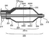
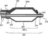
- FIG. 14 shows a plan view of the distal portion of the second balloon catheter 200 shown in FIG. 13 as viewed from the lumen side.
- FIG. 15 shows an XV-XV cross-sectional view of the second balloon catheter 200 shown in FIG.
- FIG. 16 represents a plan view of the distal portion of the second balloon catheter 200 according to another embodiment of the present invention as viewed from the lumen side.
- FIG. 17 shows a cross-sectional view of the second balloon catheter 200 shown in FIG. 16 XVII-XVII.
- FIG. 16 shows an overall view of the second balloon catheter 200 according to the embodiment of the present invention.
- FIG. 14 shows a plan view of the distal portion of the second balloon catheter 200 shown in FIG. 13 as viewed from the lumen side.
- FIG. 15 shows an XV-XV cross-sectional view of the second balloon catheter 200 shown in FIG.
- FIG. 16 represents a plan view of
- FIG. 18 represents an XVIII-XVIII cross-sectional view of the second balloon catheter 200 shown in FIG. 13, that is, a cross-sectional view perpendicular to the perspective of the portion where the lumen is arranged along the shaft.
- FIG. 19 represents a XIV-XIV cross-sectional view of the second balloon catheter 200 shown in FIG. 14, that is, a cross-sectional view perpendicular to the perspective direction of a portion where an opening is not arranged in the lumen.
- FIG. 20 shows a cross-sectional view showing another example of the XIV-XIV cross-sectional view of the second balloon catheter 200 shown in FIG. 14, and
- FIG. 21 shows the XVI- of the second balloon catheter 200 shown in FIG.
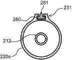
- FIG. 22 shows a cross-sectional view of XXII-XXII of the second balloon catheter 200 shown in FIG. 14, that is, a cross-sectional view perpendicular to the perspective direction of the portion where the opening is arranged in the lumen
- FIG. 23 is shown in FIG.
- a modified example of the cross-sectional view of the XXII-XXII of the second balloon catheter 200 shown is shown.
- FIG. 24 shows a cross-sectional view perpendicular to the perspective direction when the long body is not inserted into the second balloon catheter 200 shown in FIG. 22.
- FIG. 25 shows an enlarged view of the lumen portion of the cross-sectional view shown in FIG.
- FIG. 26 shows an enlarged view of the lumen portion of the cross-sectional view shown in FIG. 24.
- FIG. 27 shows a sectional view of the distal portion of the second balloon catheter 200 according to another embodiment of the present invention perpendicular to the perspective direction
- FIG. 28 shows a second embodiment according to still another embodiment of the present invention.
- FIG. 6 shows a cross-sectional view of the distal portion of the balloon catheter 200 perpendicular to the perspective direction.
- 29 shows a cross-sectional view of the second balloon catheter 200 shown in FIG. 27, and
- FIG. 30 shows a modified example of the cross-sectional view of the balloon catheter 200 shown in FIG. 27.
- FIG. 31 shows a cross-sectional view when the long body is not inserted into the second balloon catheter 200 shown in FIG. 29.
- FIG. 32 shows a cross-sectional view of the second balloon catheter 200 shown in FIG. 27, XXXII-XXXII.
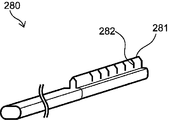
- FIG. 33 shows a perspective view of a long body according to an embodiment of the present invention
- FIG. 34 shows a perspective view of a long body according to another embodiment of the present invention.
- the second balloon catheter 200 has a shaft 210 extending in the perspective direction and a balloon 220 provided on the distal side of the shaft 210. , A long body 280 extending in the perspective along the shaft 210 and the balloon 220, and a lumen 230 extending in the perspective along the shaft 210 and the balloon 220 through which the long body 280 can be inserted.
- the proximal end of the lumen 230 is located proximal to the shaft 210 with an insertion slot for the elongated body 280, and the balloon 220 is an extension that is not fixed to the shaft 210.
- the lumen 230 has an opening 230a extending radially outward in the extension 220e, and the proximal end of the opening 230a is the extension.
- the lumen 230 Arranged distal to the proximal end of the 220e, the lumen 230 has an opening distal to the proximal end of the lumen 230 and proximal to the proximal end of the opening 230a.
- the lumen 230 is engaged with the long body 280 so that the long body 280 does not rotate more than 60 degrees in the rotation direction about the perspective direction at least a part of the opening 230a.
- the distal side refers to the direction of the subject to be treated with respect to the extending direction of the shaft 210
- the proximal side is the opposite side of the distal side. That is, it refers to the direction on the user's hand side with respect to the extending direction of the shaft 210.
- the direction from the proximal side to the distal side and the direction from the distal side to the proximal side of the shaft 210 are referred to as a perspective direction.
- the long body 280 extends in the perspective direction along the shaft 210 and the balloon 220, and can be inserted into the lumen 230.
- the elongated body 280 may have a biological tissue contact portion 281 at the distal end acting on the living body, and the configuration thereof is shown in FIGS. 4 and 5 showing the elongated body 180 of the first balloon catheter 100. And the above description for the elongated body 180 can be referred to.
- the biological tissue contact portion 281 acts on the lesion portion to fix the balloon 220 to the lesion portion, and the biological tissue contact portion 281 can excise the stenotic portion or the like occurring in the lesion portion.
- the cross-sectional shape of the elongated body 280 that is perpendicular to the perspective direction of the portion where the living tissue contact portion 281 is not provided shall be, for example, a circular shape, an elliptical shape, a polygonal shape, a shape obtained by combining these, or any other shape. However, it is preferably circular. Here, the term "circle” does not mean only a perfect circle, but includes all circular shapes. If the cross-sectional shape of the long body 280 perpendicular to the perspective direction is circular in the portion where the living tissue contact portion 281 is not provided, the long body 280 can be easily inserted into the lumen 230.
- FIG. 33 the cross-sectional shape of the portion where the biological tissue contact portion 281 is not provided is circular, and the cross-sectional shape of the portion where the biological tissue contact portion 281 is provided is substantially fan-shaped.
- FIG. 34 shows a perspective view of the long body 280, which has an elliptical cross-sectional shape perpendicular to the perspective direction of the portion where the biological tissue contact portion 281 is not provided, and a portion where the biological tissue contact portion 281 is provided.
- a perspective view of a long body 280 having a convex cross-sectional shape perpendicular to the perspective direction of the above is shown.
- the cross-sectional shapes of the elongated body 280 perpendicular to the perspective direction may be different in the perspective direction.
- the distal end of the elongated body 280 may have a tapered shape. If the distal end of the elongated body 280 has a tapered shape, it is easy to insert the elongated body 280 into the lumen 230, or the distal end of the elongated body 280 after delivery to the lesion. This has the effect of reducing the risk of damaging living tissue.
- the major axis d of the long body 280 in the cross section perpendicular to the perspective direction is preferably 0.1 mm or more, more preferably 0.15 mm or more, still more preferably 0.2 mm or more.
- the major axis d of the long body 280 is preferably 1 mm or less, more preferably 0.9 mm or less, and even more preferably 0.8 mm or less.
- the major axis d of the elongated body 280 is within the above range, it becomes easy to insert the elongated body 280 into the lumen 230, and the balloon 220 is inserted into the lesion portion without deteriorating the insertability of the second balloon catheter 200. Can be delivered to.
- the major axis is the diameter of a virtual circle inscribed by a cross section perpendicular to the perspective direction of the elongated body 280, and if the cross section perpendicular to the perspective direction of the elongated body 280 is circular, the diameter of the circle. The diameter.
- the elongated body 280 has a portion where the living tissue contact portion 281 is provided and a portion where the living tissue contact portion 281 is not provided, and the cross-sectional shape perpendicular to the perspective direction differs depending on the location in the perspective direction. Therefore, the major axis d may be different in the perspective direction, but it is preferable that the major axis d is within the above range in any cross section.
- FIG. 4 showing the elongated body 180 of the first balloon catheter 100 can be referred to.
- Examples of the material constituting the long body 280 include metals such as stainless steel, titanium, nickel-titanium alloy, cobalt-chromium alloy, and tungsten alloy; polyarylate fiber, aramid fiber, ultrahigh molecular weight polyethylene fiber, PBO fiber, and carbon fiber. Fiber materials made of synthetic resins such as, and ceramics made of alumina, zirconia, barium titanate, etc. can be mentioned. Only one type of these may be used, two or more types may be used in combination, and the fiber material may be monofilament or multifilament.
- the lumen 230 may extend in the perspective direction along the shaft 210 and the balloon 220, and particularly in the portion along the balloon 220, the lumen 230 is arranged straight without having an angle with respect to the central axis of the balloon 220. It may be arranged spirally at an angle with respect to the central axis of the balloon 220.
- the arrangement of the lumen 230 along the balloon 220 such as a linear shape or a spiral shape, may be selected in an optimum manner according to the lesion portion to be treated.
- the proximal end of the lumen 230 is located proximal to the shaft 210 and is provided with an insertion slot for a long body 280 (not shown).
- the long body 280 can be inserted from this insertion port, and the long body 280 can be inserted into the lumen 230.
- the elongated body 280 may be placed in the lumen 230 from the beginning, or may be inserted after the balloon 220 has been delivered to the lesion. Further, it is preferable that the long body 280 is slidable in the lumen 230.
- the elongated body 280 is arranged for fixing the balloon 220 to the lesion or excising the stenosis or the like occurring in the lesion, but the elongated body 280 is slidable in the lumen 230. By being there, the elongated body 280 can be arranged at an arbitrary perspective position. Further, in the embodiment in which the elongated body 280 is inserted into the lumen 230 after the balloon 220 is delivered to the lesion portion, the balloon 220 is easily facilitated without reducing the passage of the balloon 220 into the blood vessel due to the rigidity of the elongated body 280. It is preferable because it can be delivered to the lesion.
- the elongated body 280 By arranging the elongated body 280 on the lumen 230 along the shaft 210 and the balloon 220, the elongated body 280 is guided by the lumen 230, and the elongated body 280 causes an unintended deviation in the circumferential direction of the shaft 210 and the balloon 220. Prevent it from occurring and being inserted. This makes it possible to deliver the elongated body 280 to the desired position. In particular, by arranging the elongated body 280 in the lumen 230 along the balloon 220 delivered to the lesion, it is possible to prevent the elongated body 280 from being unintentionally displaced in the circumferential direction in the lesion.
- the deviation of the long body 280 in the circumferential direction means that the long body 280 moves in an unintended direction on the outer surface of the balloon 220. Therefore, when the lumen 230 is spirally arranged along the balloon 220 at an angle with respect to the central axis of the shuttle 210, the elongated body 280 inserted through the lumen 230 is the perspective of the balloon 220. It will proceed spirally with respect to the direction, but this does not correspond to the fact that the elongated body 280 is displaced in the circumferential direction of the balloon 220. The deviation means that the long body 280 moves in an unintended direction.
- the cross-sectional shape perpendicular to the perspective direction in the portion of the lumen 230 that does not have the opening 230a may be circular.
- the term "circular” does not mean only a perfect circle, but includes all circular shapes.
- the cross-sectional shape of the lumen 230 perpendicular to the perspective direction may be an ellipse, a polygon, a combination thereof, or any other shape.
- the lumen 230 may have different cross-sectional shapes in the perspective direction.
- the cross-sectional shape of the lumen 230 perpendicular to the perspective direction is preferably circular.
- the cross-sectional shape of the lumen 230 along the shaft 210 is circular, the long body 280 can be easily inserted.
- the cross-sectional shape of the portion of the lumen 230 that does not have the opening 230a, which is perpendicular to the perspective direction may be circular as shown in FIGS. 19 to 21, or the above. It may have an arbitrary shape, or may have a shape corresponding to the cross-sectional shape of the long body 280 arranged in the lumen 230.
- the cross-sectional shape of the lumen 230 perpendicular to the perspective direction corresponds to the cross-sectional shape of the long body 280, the axial rotation of the long body 280 at the portion of the lumen 230 that does not have the opening 230a along the balloon 220. Is preferable because it can suppress the above to some extent.
- the major axis of the cross section of the lumen 230 perpendicular to the perspective direction is preferably 0.2 mm or more, more preferably 0.3 mm or more, and further preferably 0.5 mm or more.
- the major axis of the cross section of the lumen 230 perpendicular to the perspective direction is preferably 1.2 mm or less, more preferably 1 mm or less, and even more preferably 0.8 mm or less.
- the major axis of the cross section perpendicular to the perspective direction of the lumen 230 is the diameter of the virtual circle inscribed by the cross section perpendicular to the perspective direction of the lumen 230, similarly to the major axis d of the elongated body 280, and the perspective of the lumen 230. If the cross section perpendicular to the direction is circular, it is the diameter of the circle.
- the cross-sectional shape perpendicular to the perspective direction may be different depending on the location in the perspective direction, and the major axis of the cross section may be different, but the major axis is in the above range in any of the cross sections. It is preferably inside.
- 19 to 21 are XIX-XIX cross-sectional views of the second balloon catheter 200 shown in FIG. 14 in different embodiments, and is a cross-sectional view of a portion of the lumen 230 along the balloon 220 that does not have an opening 230a.
- the figure is shown.
- only one lumen 230 may be provided, or a plurality of lumens 230 may be provided as shown in FIG.
- the number of lumens 230 is 1 or more, may be 2 or more, and may be 3 or more.
- the number of lumens 230 is preferably 6 or less, more preferably 5 or less, and even more preferably 4 or less.
- the lumen 230 may be formed radially outward with respect to the balloon 220.
- the guided elongated body 280, a drug, or the like can be arranged radially outward of the balloon 220, and the elongated body 280 can be arranged. And drugs can easily act on the lesion.
- at least a part of the lumen 230 may be formed on the outer side in the radial direction of the balloon 220, and the other part may be formed on the inner side of the balloon 220. This is preferable because the outer diameter of the balloon 220 and the lumen 230 combined can be kept small and the insertability in the blood vessel can be improved.
- the above configuration is the same for the portion where the lumen 230 is along the shaft 210.
- the balloon 220 is arranged on the extension portion 220e not fixed to the shaft 210, the proximal side fixing portion 221 arranged on the proximal side of the expansion portion 220e and connected to the shaft 210, and the distal side of the expansion portion 220e. It has a distal side fixing portion 225 connected to the shaft 210, and as shown in FIGS. 13 to 17, the lumen 230 is near and far outward in the radial direction of the balloon 220 in the expansion portion 220e. It has an opening 230a extending in the direction, and the proximal end of the opening 230a is located distal to the proximal end of the extension 220e.
- a part of the elongated body 280 is exposed from the opening 230a, and the exposed elongated body 280 can act on the lesion portion.
- those parts are also included in the proximal side fixing part 221 and the distal side fixing part 225.
- the distal end of the opening 230a may be the distal end 230d of the lumen 230.
- the distal end 230d of the lumen 230 has an outlet through which the elongated body 280 can move forward and backward, and the distal side of the elongated body 280 may be exposed from the outlet.
- the distal end 230d of the lumen 230 may be arranged distal to the distal end of the opening 230a. That is, a lumen 230 having no opening is arranged beyond the distal end of the opening 230a, guides the elongated body 280 beyond the opening 230a, and is provided at the distal end 230d of the lumen 230.
- the distal side of the elongated body 280 may be exposed from the outlet.
- the elongated body 280 is repeatedly expanded and contracted while advancing the balloon 220.
- the lesion can be treated by a crawling forward technique or the like in which an incision is made with a balloon.
- the expansion portion 220e includes a straight pipe portion 223, a proximal taper portion 222 arranged on the proximal side of the straight pipe portion 223, and a distal taper portion arranged on the distal side of the straight pipe portion 223. It has 224, and as shown in FIGS. 14 to 17, it is preferable that the proximal end of the opening 230a is arranged in the proximal tapered portion 222. It is preferable that the proximal taper portion 222 and the distal taper portion 224 are formed so as to reduce in diameter as the distance from the straight pipe portion 223 increases.
- the balloon 220 Since the balloon 220 has the straight tube portion 223, it is possible to sufficiently secure a portion of the straight tube portion 223 where the balloon 220 can expand most in the radial direction in contact with the lesion portion, and the balloon 220 is formed in the lesion portion. It becomes easier to expand the narrowed part. Further, since the balloon 220 has a proximal side tapered portion 222 and a distal side tapered portion 224 that reduce in diameter as the distance from the straight pipe portion 223 increases, when the balloon 220 is contracted and wound around the shaft 210, Since the outer diameters of the proximal end and the distal end of the balloon 220 can be reduced to reduce the step between the shaft 210 and the balloon 220, the balloon 220 can be easily inserted into the blood vessel.
- the elongated body 280 can be exposed from the opening 230a from the proximal tapered portion 222 to the straight pipe portion 223, so that the elongated body 280 can be exposed in a wide range.
- the body 280 can be exposed to effectively treat the lesion.
- the proximal end of the opening 230a may be located in the straight pipe portion 223. Since the elongated body 280 can be exposed in the straight tube portion 223 in which the balloon 220 can be expanded most in the radial direction and a portion in contact with the lesion portion can be sufficiently secured, the lesion portion can be effectively treated.
- the distal end of the opening 230a may be located in the straight tube portion 223 or in the distal tapered portion 224. If the distal end of the opening 230a is located in the straight tube 223, the elongated body 280 is exposed in the straight tube 223 where the balloon 220 can be expanded most in the radial direction and a portion in contact with the lesion can be sufficiently secured. Can be made to. If the distal end of the opening 230a is located at the distal taper 224, the elongated body 280 can be exposed at the distal end of the balloon 220.
- the perspective length of the opening 230a is preferably 1/10 or more, more preferably 1/5 or more, and even more preferably 1/2 or more of the perspective length of the expansion portion 220e. Further, the length of the opening 230a in the perspective direction is preferably 1 time or less, more preferably 9/10 or less, further preferably 4/5 or less, and 2/3 or less of the length of the expansion portion 220e in the perspective direction. There may be. Further, the opening 230a may be continuously provided or discontinuously provided in the expansion 220e. When the perspective length of the opening 230a is within the above range with respect to the perspective length of the expansion 220e, the elongated body 280 can be exposed from the opening 230a to treat the lesion.
- the lumen 230 does not have an opening between the proximal end of the lumen 230 and the proximal end of the opening 230a. Since the lumen 230 does not have an opening in the above range, it prevents the elongated body 280 from being exposed where it is not needed, protects the elongated body 280, and prevents damage to living tissue by the elongated body 280. Can be done.
- the lumen 230 is engaged with the long body 280 so that the long body 280 does not rotate more than 60 degrees in the rotation direction about the perspective direction at least a part of the portion having the opening 230a. It has two engaging portions 231.
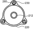
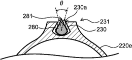
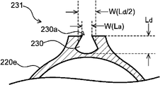
- FIG. 22 is a cross-sectional view perpendicular to the perspective direction of the second engaging portion 231 with which the long body 280 is engaged
- FIG. 23 is a perspective view of the second engaging portion 231 with which the long body 280 is engaged.
- FIG. 24 shows a cross-sectional view perpendicular to the perspective direction of the opening 230a in the second engaging portion 231 shown in FIG. 22, and FIG.
- FIG. 25 shows an enlarged view of the lumen 230 portion of the cross-sectional view shown in FIG.
- the fact that the lumen 230 and the long body 280 are engaged so as to hinder the rotation of the long body 280 means that the lumen 230 hinders the axial rotation of the long body 280 in the perspective direction. It means that the movement of the long body 280 is restricted, but not only when the lumen 230 and the long body 280 are fixed to each other so as to prevent any rotation as shown in FIG. 23, FIG. 22 Also, as shown in FIG. 25, the lumen 230 restricts the movement of the long body 280 to such an extent that the long body 280 has some play in the rotation direction about the perspective direction.
- the long body 280 does not rotate about 60 degrees or more in the rotation direction about the perspective direction in the second engaging portion 231.
- the angle ⁇ of the axial rotation of the long body 280 is such that the line connecting one of the points where the long body 280 touches the circumscribed circle and the center of gravity of the long body 280 rotates in the axial direction of the long body 280. It can be determined by measuring.
- FIG. 25 shows an example in which one of the points where the long body 280 touches the circumscribed circle is the living tissue contact portion 281. However, one point among the points where the long body 280 touches the circumscribed circle is unique. Therefore, the angle ⁇ of the axial rotation point can be obtained.
- the angle ⁇ of the axial rotation of the long body 280 in the second engaging portion 231 is more preferably 40 degrees or less, further preferably 20 degrees or less, and most preferably 0 degrees (that is, there is no play).
- the long body 280 can rotate about the axis in the range of 5 degrees or more and 60 degrees or less.
- the elongated body 280 is more preferably axially rotatable by 7 degrees or more, and may be 10 degrees or more, 12 degrees or more, or 15 degrees or more.
- the axial rotation angle of the long body 280 in the second engaging portion 231 is within the above range, it is possible to facilitate the insertion into the body cavity while controlling the axial rotation of the long body 280. It can be easily inserted even at the bent portion of the body cavity without being disengaged.
- the lumen 230 is long because at least a part of the portion having the opening 230a has a second engaging portion 231 that is engaged with the elongated body 280 so as to prevent the elongated body 280 from rotating.
- the axial rotation of the long body 280 can be prevented at the portion where a part of the long body 280 is exposed and acts on the living tissue, and the long body 280 can be brought into contact with the living tissue at a desired angle.
- the width W (L a) at the opening 230a of the lumen 230 has a width W at half the depth of the lumen depth L d (part of the L d / 2) (L d / Smaller than 2).
- FIG. 26 shows an example of the width W (L a ) at the opening 230 a of the lumen 230 and the width W (L d / 2) at half the depth (L d / 2) of the lumen depth L d. ..
- the second engaging portion 231 may be continuously arranged in the perspective direction from the proximal end to the distal end of the opening 230a of the lumen 230, or distal from the proximal end of the opening 230a of the lumen 230. It may be located in a part between the edges.
- the perspective length of the second engaging portion 231 is the opening 230a.
- the length in the perspective direction is preferably 10% or more, more preferably 20% or more, further preferably 30% or more, and particularly preferably 50% or more. If the perspective length of the second engaging portion 231 is greater than or equal to the above-mentioned length of the opening 230a in the perspective direction, it is possible to prevent the axial rotation of the elongated body 280.
- the lumen 230 is engaged with the portion of the long body 280 other than the biological tissue contact portion 281 in the second engaging portion 231.
- the living tissue contact portion 281 can be exposed from the opening 230a without being hindered by the engagement with the living tissue 230, and the living tissue contact portion 281 can be exposed. Can be brought into contact with the lesion.
- the living tissue contact portion 281 is arranged outside the opening 230a in the radial direction of the expansion portion 220e.
- the biological tissue contact portion 281 is arranged outside the opening 230a in the radial direction of the expansion portion 220e in a natural state in which pressure is not applied to the balloon 220 or the lumen 230.
- the balloon 220 can be delivered to the lesion and then the elongated body 280 can be inserted through the lumen 230 and delivered to the lesion, the living tissue contact portion 281 can be delivered to the lesion in a natural state. Even if it is arranged outside the opening 230a in the radial direction of 220e, the treatment can be performed without unnecessarily abutting or damaging the living tissue.
- the lumen 230 does not have a concave portion or a convex portion extending in the longitudinal direction in the lumen. That is, the lumen 230 has, for example, a concave portion into which the protruding portion formed in the elongated body 280 enters and a convex portion entering into the groove portion formed in the elongated body 280 as a means for forming the second engaging portion 231. It is preferable that there is no such thing. Since the lumen 230 does not have a concave portion or a convex portion extending in the longitudinal direction in the lumen, the second engaging portion 231 can be provided while easily inserting the long body 280 into the lumen 230. it can. As a result, the long body 280 can be rotated in a range of 60 degrees or less, and the long body 280 can be flexibly inserted into the lumen 230 even in a bent body cavity.
- the cross-sectional shape of the lumen 230 perpendicular to the perspective direction continuously changes in the section from the point proximal to the second engaging portion 231 to the second engaging portion 231 in the perspective direction. If the second engaging portion 231 is formed by such continuous changes, the shaft rotation is gradually controlled in the process of guiding the long body 280 to the second engaging portion 231, and the second engaging portion is formed. At 231 the elongated body 280 is preferred because it is easily engaged with the lumen 230.
- the lumen 230 is located distal to the distal end of the opening 230a at the same position as the distal end of the elongated body 280 or from the distal end of the elongated body 280.
- the stopper 233 may be arranged in the straight pipe portion 223 as shown in FIG. 27, may be arranged in the distal taper portion 224 as shown in FIG. 28, or may be arranged in the distal side taper portion 224 as shown in FIG. It may be arranged in the side fixing portion 225. Depending on where the stopper 233 is placed and where the distal end of the opening 230a is placed, it is possible to select where in the balloon 220 the elongated body 280 is exposed. For example, as shown in FIG. 28, if the stopper 233 is arranged on the distal taper portion 224 and the distal end of the opening 230a is also arranged on the distal taper portion 224, the elongated body 280 is straightened.
- the lesion portion can be exposed by a swelling forward technique or the like in which the balloon 220 is repeatedly expanded and contracted while the balloon 220 is advanced to make an incision with a long body 280. Can be treated.
- the means for providing the stopper 233 is not particularly limited, but for example, the lumen 230 provided as shown in FIG. 31 can be provided by crushing as shown in FIG. 32.
- the long body 280 inserted through the lumen 230 as shown in FIGS. 29 and 30 crushes the lumen 230 as shown in FIG. 32, the crushed portion of the lumen 230 becomes a stopper 233 and becomes long.
- the scale 280 does not progress distal to it.
- FIG. 29 shows an aspect in which there is play in the axial rotation of the long body 280 in the second engaging portion 231
- FIG. 30 shows a play in the axial rotation of the long body 280 in the second engaging portion 231.
- the stopper 233 can prevent the elongated body 280 from advancing to the distal side.
- the long body 280 arranged in the expansion portion 220e is provided with one or more notches 282.
- the number of cuts 282 is preferably 2 or more, more preferably 3 or more, further preferably 5 or more, and the number of cuts 282 is preferably 20 or less, more preferably 15 or less, still more preferably 12 or less. Within the range of the number of cuts 282, the flexibility can be improved without impairing the strength of the long body 280.
- the notch 282 is provided on the side of the elongated body 280 where the biological tissue contact portion 281 is provided.
- the orientation and size of the notch 282 are not limited as long as the flexibility can be improved without impairing the strength of the elongated body 280.
- the notch 282 may be provided at an angle perpendicular to or other than the axial direction of the elongated body 280, and each of the plurality of notches 282 provided as shown in FIG. 33 is provided with respect to the axial direction of the elongated body 280. It may be provided at different angles, or as shown in FIG.
- each of the plurality of notches 282 may be provided at the same angle with respect to the axial direction of the elongated body 280.
- FIG. 13 shows a configuration example of a so-called over-the-wire type balloon catheter 200 in which a guide wire for guiding the progress of the balloon catheter 200 is inserted from the distal side to the proximal side of the shaft 210.
- the second balloon catheter 200 can also be applied to a so-called rapid exchange type balloon catheter in which a guide wire is inserted halfway from the distal side to the proximal side of the shaft 210.
- the balloon catheter 200 is configured so that fluid is supplied to the inside of the balloon 220 through the shaft 210, and the expansion and contraction of the balloon 220 can be controlled by using an indeflator (balloon pressurizer).
- the fluid may be a pressure fluid pressurized by a pump or the like.
- a fluid flow path is provided inside the shaft 210. Further, it is preferable that the shaft 210 has a guide wire insertion passage inside.
- the shaft 210 has an outer pipe 211 and an inner pipe 212.
- the inner pipe 212 functions as an insertion passage for a guide wire, and the space between the inner pipe 212 and the outer pipe 211 functions as a fluid flow path.
- the inner tube 212 extends from the distal end of the outer tube 211 and penetrates the balloon 220 in the perspective direction, and the proximal side of the balloon 220 is the outer tube 211. It is preferable that the balloon 220 is fixed to the inner tube 212 on the distal side.
- the material constituting the shaft 210 examples include polyamide-based resin, polyester-based resin, polyurethane-based resin, polyolefin-based resin, fluorine-based resin, vinyl chloride-based resin, silicone-based resin, and natural rubber. Only one type of these may be used, or two or more types may be used in combination. Above all, the material constituting the shaft 210 is preferably at least one of a polyamide resin, a polyolefin resin, and a fluorine resin. Since the material constituting the shaft 210 is at least one of a polyamide resin, a polyolefin resin, and a fluorine resin, the slipperiness of the surface of the shaft 210 is enhanced, and the passability of the balloon catheter 200 through the blood vessels is improved. be able to.
- Examples of the material constituting the balloon 220 include at least one selected from the group consisting of polyamide-based resin, polyester-based resin, polyurethane-based resin, polyolefin-based resin, vinyl chloride-based resin, silicone-based resin, and natural rubber. .. Of these, at least one selected from the group consisting of polyamide-based resins, polyester-based resins, and polyurethane-based resins is preferable. Moreover, you may use an elastomer resin as these resins.
- the balloon 220 can be manufactured by molding a resin.
- the balloon 220 can be manufactured by arranging a resin tube extruded by extrusion molding in a mold and performing biaxial stretching blow molding.
- the balloon 220 can also be manufactured by a known molding method such as dip molding, injection molding, or compression molding.
- the portion forming the lumen 230 along the balloon 220 is preferably integrally molded with the balloon 220.
- integrally molding the lumen 230 with the balloon 220 it becomes easy to form the lumen 230.
- the balloon 220 is manufactured by extrusion molding as described above while securing the lumen with a core material for forming the lumen or high-pressure air. Can be mentioned.
- the portion forming the lumen 230 along the shaft 210 may be integrally formed with the shaft 210, or may be formed by a tubular member different from the shaft 210 and joined to the shaft 210. If the portion forming the lumen 230 along the shaft 210 is integrally molded with the shaft 210, it becomes easy to form the lumen 230 by extrusion molding or the like as in the portion along the balloon 220. Further, if the portion forming the lumen 230 along the shaft 210 is formed by a tubular member different from the shaft 210, comparison can be made regardless of the shape of the lumen 230 along the shaft 210. It can be easily manufactured.
- the material constituting the tubular member can refer to the material constituting the shaft 210, and may be the same as or different from the material constituting the shaft 210.
- the shaft 210 and the tubular member can be joined by an existing method such as adhesion with an adhesive or welding.
- the dimensions of the balloon 220 are preferably 5 mm to 300 mm in the perspective direction and 0.5 mm to 12 mm in the outer diameter when the lesion is a blood vessel, and when the lesion is a gastrointestinal tract such as the duodenal papilla. It is preferable that the length in the perspective direction is 10 mm to 100 mm and the outer diameter is 3 mm to 30 mm.
- Fixing of the shaft 210 and the balloon 220 includes, for example, adhesion and welding with an adhesive, and caulking by attaching a ring-shaped member to a portion where the shaft 210 and the end of the balloon 220 overlap. Above all, it is preferable that the shaft 210 and the balloon 220 are fixed by welding. Since the shaft 210 and the balloon 220 are welded together, the fixing between the shaft 210 and the balloon 220 is difficult to be released even if the balloon 220 is repeatedly expanded and contracted, and the fixing strength between the shaft 210 and the balloon 220 is easily increased. be able to.
- the balloon catheter 200 may have a hub 204 on the proximal side of the shaft 210 to deliver fluid to the shaft 210.
- the hub 204 preferably has a fluid injection portion 206 communicating with the fluid flow path supplied inside the balloon 220 and a guide wire insertion portion 205 communicating with the guide wire insertion passage. Since the balloon catheter 200 has a hub 204 including a fluid injection portion 206 and a guide wire insertion portion 205, an operation of supplying fluid to the inside of the balloon 220 to expand and contract the balloon 220 and along the guide wire can be performed.
- the balloon catheter 200 can be easily delivered to the lesion.
- Fixing of the shaft 210 and the hub 204 includes, for example, adhesion with an adhesive, welding, and the like. Above all, it is preferable that the shaft 210 and the hub 204 are fixed by adhesion. If the shaft 210 and the hub 204 are fixed by adhesion, for example, the shaft 210 is made of a highly flexible material, the hub 204 is made of a highly rigid material, and so on. When the material constituting the hub 204 is different, the fixing strength between the shaft 210 and the hub 204 can be increased to increase the durability of the balloon catheter 200.
- a chemical injection port may be provided in the proximal portion of the shaft 210.
- the drug solution injected from the drug solution injection port is introduced into the lumen 230 by a tube communicating with the lumen 230, and is discharged from the distal end 230d of the lumen 230 and / or the opening 230a provided in the lumen 230 to form a lesion. Can be administered to.
- the drug solution can be injected after the balloon 220 is delivered to the lesion and the drug solution can be delivered to the lesion by the lumen 230. It is possible to effectively administer the drug to the lesion without losing the drug in the drug solution during delivery.
- the drug contained in the drug solution injected from the drug solution injection port is not particularly limited as long as it is a pharmacologically active substance, and examples thereof include non-gene therapy drugs, gene therapy drugs, small molecules, cells, and other drugs that are acceptable as drugs. Be done.
- anti-restenosis agents such as antiproliferative agents and immunosuppressive agents can be preferably used as agents.
- drugs such as paclitaxel, sirolimus (rapamycin), everolimus, and zotarolimus can be used. Only one of these agents may be used, or two or more of these agents may be used.
- the third balloon catheter may be a balloon catheter having both a first engaging portion 131 and a second engaging portion 231, or a second balloon catheter 200 having a first engaging portion 131. It may be a balloon catheter with preferred requirements.
- Such a balloon catheter can prevent the long body from rotating in the axial direction and shifting in the circumferential direction on the balloon, and can bring the long body into contact with the lesion at a desired angle.
- First balloon catheter 104 Hub 105 of the first balloon catheter: Guide wire insertion part 106 of the first balloon catheter: Fluid injection part 110 of the first balloon catheter: Shaft 111 of the first balloon catheter: Outer tube of the shaft of the first balloon catheter 112: Inner tube of the shaft of the first balloon catheter 120: Balloon 120e of the first balloon catheter: Expansion portion of the first balloon catheter 120f: Fixation of the first balloon catheter Part 121: Proximal taper portion 122 of the first balloon catheter: Straight tube portion 123 of the first balloon catheter: Distal taper portion 130 of the first balloon catheter: Lumen 130d for long body: Long body Distal end 131 of the lumen for use: First engaging portion 180: Elongated body of the first balloon catheter 181: Living tissue contact portion of the first balloon catheter 200: Second balloon catheter 204: Second balloon catheter Hub 205: Guide wire insertion part of the second balloon catheter 206: Fluid injection part of the second balloon catheter 210: Shaft of the second balloon catheter 211: Outer tube of the shaft of the second balloon
Landscapes
- Health & Medical Sciences (AREA)
- Life Sciences & Earth Sciences (AREA)
- Heart & Thoracic Surgery (AREA)
- Animal Behavior & Ethology (AREA)
- Vascular Medicine (AREA)
- Veterinary Medicine (AREA)
- Public Health (AREA)
- Engineering & Computer Science (AREA)
- General Health & Medical Sciences (AREA)
- Biomedical Technology (AREA)
- Surgery (AREA)
- Hematology (AREA)
- Anesthesiology (AREA)
- Pulmonology (AREA)
- Biophysics (AREA)
- Child & Adolescent Psychology (AREA)
- Nuclear Medicine, Radiotherapy & Molecular Imaging (AREA)
- Medical Informatics (AREA)
- Molecular Biology (AREA)
- Media Introduction/Drainage Providing Device (AREA)
Priority Applications (2)
| Application Number | Priority Date | Filing Date | Title |
|---|---|---|---|
| JP2021565558A JP7557479B2 (ja) | 2019-12-20 | 2020-12-11 | バルーンカテーテル |
| US17/841,916 US12274467B2 (en) | 2019-12-20 | 2022-06-16 | Balloon catheter |
Applications Claiming Priority (4)
| Application Number | Priority Date | Filing Date | Title |
|---|---|---|---|
| JP2019230874 | 2019-12-20 | ||
| JP2019230875 | 2019-12-20 | ||
| JP2019-230875 | 2019-12-20 | ||
| JP2019-230874 | 2019-12-20 |
Related Child Applications (1)
| Application Number | Title | Priority Date | Filing Date |
|---|---|---|---|
| US17/841,916 Continuation US12274467B2 (en) | 2019-12-20 | 2022-06-16 | Balloon catheter |
Publications (1)
| Publication Number | Publication Date |
|---|---|
| WO2021125103A1 true WO2021125103A1 (ja) | 2021-06-24 |
Family
ID=76477484
Family Applications (1)
| Application Number | Title | Priority Date | Filing Date |
|---|---|---|---|
| PCT/JP2020/046382 Ceased WO2021125103A1 (ja) | 2019-12-20 | 2020-12-11 | バルーンカテーテル |
Country Status (3)
| Country | Link |
|---|---|
| US (1) | US12274467B2 (https=) |
| JP (1) | JP7557479B2 (https=) |
| WO (1) | WO2021125103A1 (https=) |
Cited By (3)
| Publication number | Priority date | Publication date | Assignee | Title |
|---|---|---|---|---|
| JP2024003894A (ja) * | 2022-06-28 | 2024-01-16 | 株式会社グッドマン | カテーテル用バルーン体及びバルーンカテーテル |
| WO2024106176A1 (ja) * | 2022-11-16 | 2024-05-23 | 株式会社カネカ | バルーンカテーテル用バルーン及びそれを備えるバルーンカテーテル、並びにバルーンカテーテルの製造方法 |
| WO2024106402A1 (ja) * | 2022-11-16 | 2024-05-23 | 株式会社カネカ | バルーンカテーテル用バルーン及びそれを備えるバルーンカテーテル、並びにバルーンカテーテルの製造方法 |
Citations (5)
| Publication number | Priority date | Publication date | Assignee | Title |
|---|---|---|---|---|
| US5921958A (en) * | 1992-02-10 | 1999-07-13 | Scimed Life Systems, Inc. | Intravascular catheter with distal tip guide wire lumen |
| US20080200944A1 (en) * | 2007-02-13 | 2008-08-21 | Cook Incorporated | Balloon catheter with dilating elements |
| US20090171284A1 (en) * | 2007-12-27 | 2009-07-02 | Cook Incorporated | Dilation system |
| US20110288479A1 (en) * | 2010-05-18 | 2011-11-24 | Cook, Incorporated | Balloon With Integral Retention of A Dilation Element |
| JP2020156734A (ja) * | 2019-03-26 | 2020-10-01 | テルモ株式会社 | スコアリングデバイスおよび処置方法 |
Family Cites Families (12)
| Publication number | Priority date | Publication date | Assignee | Title |
|---|---|---|---|---|
| US5531690A (en) | 1992-10-30 | 1996-07-02 | Cordis Corporation | Rapid exchange catheter |
| US5413557A (en) | 1993-08-24 | 1995-05-09 | Pameda N.V. | Dilatation catheter with eccentric balloon |
| US5315747A (en) | 1992-10-30 | 1994-05-31 | Pameda N.V. | Method of preparing a balloon dilatation catheter |
| US5669880A (en) | 1993-08-24 | 1997-09-23 | Cordis Corporation | Stent delivery system |
| US7799043B2 (en) | 2003-12-01 | 2010-09-21 | Boston Scientific Scimed, Inc. | Cutting balloon having sheathed incising elements |
| US20080228139A1 (en) | 2007-02-06 | 2008-09-18 | Cook Incorporated | Angioplasty Balloon With Concealed Wires |
| GB2485769B (en) | 2010-11-22 | 2012-12-05 | Cook Medical Technologies Llc | Scoring balloon and method of making same |
| US9011374B2 (en) | 2011-06-10 | 2015-04-21 | Cook Medical Technologies Llc | Balloon catheter with three lumens |
| CA2871300A1 (en) | 2013-11-29 | 2015-05-29 | Cook Medical Technologies Llc | Medical balloon |
| GB201419864D0 (en) | 2014-11-07 | 2014-12-24 | Cook Medical Technologies Llc | Medical balloon |
| GB2529720A (en) | 2014-09-01 | 2016-03-02 | Cook Medical Technologies Llc | Shaped or textured medical balloon with strengthening elements |
| JP2018130232A (ja) | 2017-02-14 | 2018-08-23 | テルモ株式会社 | 医療用長尺体 |
-
2020
- 2020-12-11 WO PCT/JP2020/046382 patent/WO2021125103A1/ja not_active Ceased
- 2020-12-11 JP JP2021565558A patent/JP7557479B2/ja active Active
-
2022
- 2022-06-16 US US17/841,916 patent/US12274467B2/en active Active
Patent Citations (5)
| Publication number | Priority date | Publication date | Assignee | Title |
|---|---|---|---|---|
| US5921958A (en) * | 1992-02-10 | 1999-07-13 | Scimed Life Systems, Inc. | Intravascular catheter with distal tip guide wire lumen |
| US20080200944A1 (en) * | 2007-02-13 | 2008-08-21 | Cook Incorporated | Balloon catheter with dilating elements |
| US20090171284A1 (en) * | 2007-12-27 | 2009-07-02 | Cook Incorporated | Dilation system |
| US20110288479A1 (en) * | 2010-05-18 | 2011-11-24 | Cook, Incorporated | Balloon With Integral Retention of A Dilation Element |
| JP2020156734A (ja) * | 2019-03-26 | 2020-10-01 | テルモ株式会社 | スコアリングデバイスおよび処置方法 |
Cited By (3)
| Publication number | Priority date | Publication date | Assignee | Title |
|---|---|---|---|---|
| JP2024003894A (ja) * | 2022-06-28 | 2024-01-16 | 株式会社グッドマン | カテーテル用バルーン体及びバルーンカテーテル |
| WO2024106176A1 (ja) * | 2022-11-16 | 2024-05-23 | 株式会社カネカ | バルーンカテーテル用バルーン及びそれを備えるバルーンカテーテル、並びにバルーンカテーテルの製造方法 |
| WO2024106402A1 (ja) * | 2022-11-16 | 2024-05-23 | 株式会社カネカ | バルーンカテーテル用バルーン及びそれを備えるバルーンカテーテル、並びにバルーンカテーテルの製造方法 |
Also Published As
| Publication number | Publication date |
|---|---|
| JPWO2021125103A1 (https=) | 2021-06-24 |
| US12274467B2 (en) | 2025-04-15 |
| JP7557479B2 (ja) | 2024-09-27 |
| US20220304718A1 (en) | 2022-09-29 |
Similar Documents
| Publication | Publication Date | Title |
|---|---|---|
| US8172831B2 (en) | Catheter configured for incremental rotation | |
| CA2675209A1 (en) | Rapid-exchange balloon catheter shaft and method | |
| US12274467B2 (en) | Balloon catheter | |
| KR20230108282A (ko) | 벌룬 카테터용 벌룬 | |
| WO2020195697A1 (ja) | バルーンカテーテル | |
| WO2018008514A1 (ja) | バルーンカテーテル | |
| WO2023080063A1 (ja) | バルーンカテーテル用バルーン | |
| WO2020195170A1 (ja) | バルーンカテーテル | |
| JP2008264118A (ja) | カテーテル | |
| CN118787840A (zh) | 球囊导管用球囊和球囊导管 | |
| WO2023079906A1 (ja) | バルーンカテーテル用バルーン | |
| JP7312556B2 (ja) | カテーテル | |
| US20260076709A1 (en) | Balloon for balloon catheter and balloon catheter including same | |
| US12544098B2 (en) | Medical device with blade assembly | |
| US20240390028A1 (en) | Cutting blade with shortened terminal blade segments | |
| JP2025073658A (ja) | バルーンカテーテル用バルーン及びそれを備えるバルーンカテーテル。 | |
| WO2024262527A9 (ja) | バルーンカテーテル | |
| US20250152922A1 (en) | Balloon catheter | |
| JP2025073657A (ja) | バルーンカテーテル用バルーン及びそれを備えるバルーンカテーテル | |
| JP2024171866A (ja) | バルーンカテーテル用バルーン及びそれを備えるバルーンカテーテル | |
| WO2024106402A1 (ja) | バルーンカテーテル用バルーン及びそれを備えるバルーンカテーテル、並びにバルーンカテーテルの製造方法 | |
| JP2024151847A (ja) | バルーンカテーテル用バルーンおよびバルーンカテーテル | |
| JP2024171867A (ja) | バルーンカテーテル用バルーン及びそれを備えるバルーンカテーテル | |
| JP2024151848A (ja) | バルーンカテーテル用バルーンおよびバルーンカテーテル | |
| WO2023157533A1 (ja) | バルーンカテーテル |
Legal Events
| Date | Code | Title | Description |
|---|---|---|---|
| 121 | Ep: the epo has been informed by wipo that ep was designated in this application |
Ref document number: 20901448 Country of ref document: EP Kind code of ref document: A1 |
|
| ENP | Entry into the national phase |
Ref document number: 2021565558 Country of ref document: JP Kind code of ref document: A |
|
| NENP | Non-entry into the national phase |
Ref country code: DE |
|
| 122 | Ep: pct application non-entry in european phase |
Ref document number: 20901448 Country of ref document: EP Kind code of ref document: A1 |