WO2021124530A1 - Wearable environment sensor device - Google Patents
Wearable environment sensor device Download PDFInfo
- Publication number
- WO2021124530A1 WO2021124530A1 PCT/JP2019/049953 JP2019049953W WO2021124530A1 WO 2021124530 A1 WO2021124530 A1 WO 2021124530A1 JP 2019049953 W JP2019049953 W JP 2019049953W WO 2021124530 A1 WO2021124530 A1 WO 2021124530A1
- Authority
- WO
- WIPO (PCT)
- Prior art keywords
- housing
- black
- sensor device
- temperature
- environment sensor
- Prior art date
Links
- 238000003780 insertion Methods 0.000 claims abstract description 30
- 230000037431 insertion Effects 0.000 claims abstract description 30
- 230000002093 peripheral effect Effects 0.000 claims abstract description 6
- 230000007613 environmental effect Effects 0.000 claims description 8
- 238000003466 welding Methods 0.000 abstract description 17
- 230000001681 protective effect Effects 0.000 description 13
- 239000000758 substrate Substances 0.000 description 13
- 230000000694 effects Effects 0.000 description 5
- 238000005259 measurement Methods 0.000 description 5
- 238000012545 processing Methods 0.000 description 5
- 238000007789 sealing Methods 0.000 description 5
- 238000010586 diagram Methods 0.000 description 4
- XLYOFNOQVPJJNP-UHFFFAOYSA-N water Substances O XLYOFNOQVPJJNP-UHFFFAOYSA-N 0.000 description 4
- 239000000853 adhesive Substances 0.000 description 3
- 230000001070 adhesive effect Effects 0.000 description 3
- 239000000463 material Substances 0.000 description 3
- 238000012856 packing Methods 0.000 description 3
- 210000004243 sweat Anatomy 0.000 description 3
- 229920003002 synthetic resin Polymers 0.000 description 3
- 239000000057 synthetic resin Substances 0.000 description 3
- 206010019345 Heat stroke Diseases 0.000 description 2
- 238000009413 insulation Methods 0.000 description 2
- WABPQHHGFIMREM-UHFFFAOYSA-N lead(0) Chemical compound [Pb] WABPQHHGFIMREM-UHFFFAOYSA-N 0.000 description 2
- 230000005855 radiation Effects 0.000 description 2
- 239000004065 semiconductor Substances 0.000 description 2
- 230000035945 sensitivity Effects 0.000 description 2
- 238000009423 ventilation Methods 0.000 description 2
- 241000282412 Homo Species 0.000 description 1
- 230000002411 adverse Effects 0.000 description 1
- 230000015572 biosynthetic process Effects 0.000 description 1
- 238000006243 chemical reaction Methods 0.000 description 1
- 239000011248 coating agent Substances 0.000 description 1
- 238000004891 communication Methods 0.000 description 1
- 238000001514 detection method Methods 0.000 description 1
- 230000006866 deterioration Effects 0.000 description 1
- 238000011156 evaluation Methods 0.000 description 1
- 239000004744 fabric Substances 0.000 description 1
- 239000002184 metal Substances 0.000 description 1
- 238000000034 method Methods 0.000 description 1
- 230000002265 prevention Effects 0.000 description 1
- 230000004043 responsiveness Effects 0.000 description 1
- 229910000679 solder Inorganic materials 0.000 description 1
- 230000035900 sweating Effects 0.000 description 1
- 239000013585 weight reducing agent Substances 0.000 description 1
Images


Classifications
-
- G—PHYSICS
- G01—MEASURING; TESTING
- G01K—MEASURING TEMPERATURE; MEASURING QUANTITY OF HEAT; THERMALLY-SENSITIVE ELEMENTS NOT OTHERWISE PROVIDED FOR
- G01K1/00—Details of thermometers not specially adapted for particular types of thermometer
- G01K1/08—Protective devices, e.g. casings
-
- G—PHYSICS
- G01—MEASURING; TESTING
- G01K—MEASURING TEMPERATURE; MEASURING QUANTITY OF HEAT; THERMALLY-SENSITIVE ELEMENTS NOT OTHERWISE PROVIDED FOR
- G01K1/00—Details of thermometers not specially adapted for particular types of thermometer
- G01K1/14—Supports; Fastening devices; Arrangements for mounting thermometers in particular locations
-
- A—HUMAN NECESSITIES
- A61—MEDICAL OR VETERINARY SCIENCE; HYGIENE
- A61B—DIAGNOSIS; SURGERY; IDENTIFICATION
- A61B5/00—Measuring for diagnostic purposes; Identification of persons
- A61B5/01—Measuring temperature of body parts ; Diagnostic temperature sensing, e.g. for malignant or inflamed tissue
-
- A—HUMAN NECESSITIES
- A61—MEDICAL OR VETERINARY SCIENCE; HYGIENE
- A61B—DIAGNOSIS; SURGERY; IDENTIFICATION
- A61B5/00—Measuring for diagnostic purposes; Identification of persons
- A61B5/68—Arrangements of detecting, measuring or recording means, e.g. sensors, in relation to patient
- A61B5/6801—Arrangements of detecting, measuring or recording means, e.g. sensors, in relation to patient specially adapted to be attached to or worn on the body surface
- A61B5/6802—Sensor mounted on worn items
- A61B5/6804—Garments; Clothes
-
- G—PHYSICS
- G01—MEASURING; TESTING
- G01D—MEASURING NOT SPECIALLY ADAPTED FOR A SPECIFIC VARIABLE; ARRANGEMENTS FOR MEASURING TWO OR MORE VARIABLES NOT COVERED IN A SINGLE OTHER SUBCLASS; TARIFF METERING APPARATUS; MEASURING OR TESTING NOT OTHERWISE PROVIDED FOR
- G01D21/00—Measuring or testing not otherwise provided for
-
- G—PHYSICS
- G01—MEASURING; TESTING
- G01J—MEASUREMENT OF INTENSITY, VELOCITY, SPECTRAL CONTENT, POLARISATION, PHASE OR PULSE CHARACTERISTICS OF INFRARED, VISIBLE OR ULTRAVIOLET LIGHT; COLORIMETRY; RADIATION PYROMETRY
- G01J5/00—Radiation pyrometry, e.g. infrared or optical thermometry
- G01J5/02—Constructional details
- G01J5/0215—Compact construction
-
- G—PHYSICS
- G01—MEASURING; TESTING
- G01J—MEASUREMENT OF INTENSITY, VELOCITY, SPECTRAL CONTENT, POLARISATION, PHASE OR PULSE CHARACTERISTICS OF INFRARED, VISIBLE OR ULTRAVIOLET LIGHT; COLORIMETRY; RADIATION PYROMETRY
- G01J5/00—Radiation pyrometry, e.g. infrared or optical thermometry
- G01J5/02—Constructional details
- G01J5/04—Casings
- G01J5/041—Mountings in enclosures or in a particular environment
-
- G—PHYSICS
- G01—MEASURING; TESTING
- G01J—MEASUREMENT OF INTENSITY, VELOCITY, SPECTRAL CONTENT, POLARISATION, PHASE OR PULSE CHARACTERISTICS OF INFRARED, VISIBLE OR ULTRAVIOLET LIGHT; COLORIMETRY; RADIATION PYROMETRY
- G01J5/00—Radiation pyrometry, e.g. infrared or optical thermometry
- G01J5/02—Constructional details
- G01J5/08—Optical arrangements
- G01J5/0887—Integrating cavities mimicking black bodies, wherein the heat propagation between the black body and the measuring element does not occur within a solid; Use of bodies placed inside the fluid stream for measurement of the temperature of gases; Use of the reemission from a surface, e.g. reflective surface; Emissivity enhancement by multiple reflections
-
- G—PHYSICS
- G01—MEASURING; TESTING
- G01K—MEASURING TEMPERATURE; MEASURING QUANTITY OF HEAT; THERMALLY-SENSITIVE ELEMENTS NOT OTHERWISE PROVIDED FOR
- G01K13/00—Thermometers specially adapted for specific purposes
- G01K13/02—Thermometers specially adapted for specific purposes for measuring temperature of moving fluids or granular materials capable of flow
-
- A—HUMAN NECESSITIES
- A41—WEARING APPAREL
- A41D—OUTERWEAR; PROTECTIVE GARMENTS; ACCESSORIES
- A41D1/00—Garments
- A41D1/002—Garments adapted to accommodate electronic equipment
-
- A—HUMAN NECESSITIES
- A61—MEDICAL OR VETERINARY SCIENCE; HYGIENE
- A61B—DIAGNOSIS; SURGERY; IDENTIFICATION
- A61B2560/00—Constructional details of operational features of apparatus; Accessories for medical measuring apparatus
- A61B2560/02—Operational features
- A61B2560/0242—Operational features adapted to measure environmental factors, e.g. temperature, pollution
-
- G—PHYSICS
- G01—MEASURING; TESTING
- G01J—MEASUREMENT OF INTENSITY, VELOCITY, SPECTRAL CONTENT, POLARISATION, PHASE OR PULSE CHARACTERISTICS OF INFRARED, VISIBLE OR ULTRAVIOLET LIGHT; COLORIMETRY; RADIATION PYROMETRY
- G01J5/00—Radiation pyrometry, e.g. infrared or optical thermometry
- G01J5/02—Constructional details
- G01J5/05—Means for preventing contamination of the components of the optical system; Means for preventing obstruction of the radiation path
-
- G—PHYSICS
- G01—MEASURING; TESTING
- G01N—INVESTIGATING OR ANALYSING MATERIALS BY DETERMINING THEIR CHEMICAL OR PHYSICAL PROPERTIES
- G01N27/00—Investigating or analysing materials by the use of electric, electrochemical, or magnetic means
- G01N27/02—Investigating or analysing materials by the use of electric, electrochemical, or magnetic means by investigating impedance
- G01N27/22—Investigating or analysing materials by the use of electric, electrochemical, or magnetic means by investigating impedance by investigating capacitance
- G01N27/223—Investigating or analysing materials by the use of electric, electrochemical, or magnetic means by investigating impedance by investigating capacitance for determining moisture content, e.g. humidity
- G01N27/225—Investigating or analysing materials by the use of electric, electrochemical, or magnetic means by investigating impedance by investigating capacitance for determining moisture content, e.g. humidity by using hygroscopic materials
-
- G—PHYSICS
- G01—MEASURING; TESTING
- G01W—METEOROLOGY
- G01W1/00—Meteorology
- G01W1/02—Instruments for indicating weather conditions by measuring two or more variables, e.g. humidity, pressure, temperature, cloud cover or wind speed
Definitions
- the present invention relates to a wearable environment sensor device that measures environmental information in the vicinity of a wearing place, particularly a wearable environment sensor device that is worn on clothes or a body and measures the environmental information in clothes of a wearer.
- the heat index meter conventionally used to prevent heat stroke measures the black bulb temperature, the wet bulb temperature, and the dry bulb temperature to obtain the heat index, and the heat index is relatively high.
- a method used as a guideline for action such as avoiding going out or strenuous work, is used (see Non-Patent Document 1).
- the conventional heat index meter is generally composed of a relatively large device, and it is difficult to place it in an arbitrary place.
- the heat index published by the Ministry of the Environment is a value that represents a wide area.
- the heat load actually received by each individual is greatly affected by the local environment.
- the environment varies greatly depending on where each person is, such as outdoors and indoors, sun and shade, lawn and concrete.
- the influence of radiation from the ground for example, differs greatly between a tall adult and a short child.
- the environment of the human body changes greatly depending on the clothes worn, the state of exercise, and the state of sweating.
- a small wearable environment sensor device that can be attached to an individual's clothes or clothes to measure the environment in the immediate vicinity of the clothes or the environment inside the clothes for each individual has not been known.
- the environment sensor has problems such as highly reliable formation of internal structures such as black globes and difficulty in realizing heat insulation due to miniaturization.
- An object of the present invention is to measure the environment in the vicinity of the human body or the like with high accuracy, easily and stably.
- the wearable environment sensor device is a wearable environment sensor device configured to measure the environmental information of the wearing place, and the wearable environment sensor device is a black globe.
- the housing is provided with a black bulb temperature sensor including a temperature sensor for measuring the internal temperature of the black globe, the black globe is provided with an insertion hole for inserting the temperature sensor inside, and the black globe is the housing.
- the black ball is provided with a guide portion on the outer periphery of the insertion hole, the housing is provided with an insertion hole for inserting the guide portion of the black ball, and the housing is provided.
- a convex portion is provided on the outer periphery of the insertion hole, the guide portion is supported by the convex portion, and the welded portion of the black globe is welded to the housing in the vicinity of the outer periphery of the insertion hole of the housing. It is characterized by being.
- thermoelectric sensor device According to the wearable environment sensor device according to the present invention, temperature, humidity and environmental information can be measured with high accuracy, easily and stably.
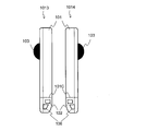
- FIG. 1A is an external view of the front surface and the back surface of the wearable environment sensor device according to the first embodiment of the present invention.
- FIG. 1B is an external view of a side surface of the wearable environment sensor device according to the first embodiment of the present invention.
- FIG. 1C is a top view of the wearable environment sensor device according to the first embodiment of the present invention.
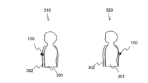
- FIG. 2 is a diagram showing a mounting example of the wearable environment sensor device according to the first embodiment of the present invention.
- FIG. 3A is a diagram showing a housing surface before joining black globes in the wearable environment sensor device according to the first embodiment of the present invention.
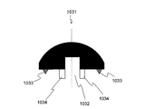
- FIG. 3B is a side view of the black globe 1031 in the wearable environment sensor device according to the first embodiment of the present invention.
- FIG. 3C is a cross-sectional view of a black sphere before the arrangement of the temperature sensor in the wearable environment sensor device according to the first embodiment of the present invention.
- FIG. 3D is a cross-sectional view of a black sphere after the temperature sensor is arranged in the wearable environment sensor device according to the first embodiment of the present invention.
- FIG. 4 is a diagram showing a convex portion in a housing in a modified example of the wearable environment sensor device according to the first embodiment.
- FIG. 5 is a cross-sectional view of a joint portion between the black globe temperature sensor and the housing in the wearable environment sensor device according to the second embodiment.
- the wearable environment sensor device 100 (hereinafter, referred to as “environment sensor device”) 100 according to the first embodiment of the present invention will be described with reference to FIGS. 1 to 5.
- FIG. 1 shows an external view of the environment sensor device 100 according to the present embodiment.
- FIG. 1A shows an external view of the front surface 1011 and the back surface 1012 of the environment sensor device 100.
- FIG. 1B shows an external view of the right side surface 1013 and the left side surface 1014.
- a top view is shown in FIG. 1C.
- the environment sensor device 100 includes a temperature / humidity sensor 102 capable of measuring air temperature and relative humidity inside the housing 101, and a black bulb temperature sensor 103 measuring the black bulb temperature on the surface 101A of the housing 101. Further, a lid 108 for battery replacement is provided on the back surface 101B of the housing 101.
- the environment sensor device 100 includes a sealed portion 104 and a protective structure (sealed outside) 105.
- the sealed portion 104 is sealed, and the sealed portion 104 and the protective structure (sealed outer surface) 105 are separated by a housing wall 101C inside the housing 101.
- the size of the environment sensor device 100 is about 50 mm in length, about 24 mm in width, and about 7 mm in thickness.
- the temperature / humidity sensor 102 is mounted on a substrate (hereinafter referred to as “sensor substrate”), and the surface on the side of the sensor substrate on which the temperature / humidity sensor 102 is mounted is referred to as a “sensor surface”.
- the temperature / humidity sensor 102 is arranged inside the protective structure (sealed outside) 105, and is covered with a protective structure for protecting the temperature / humidity sensor 102.
- the protective structure is such that the temperature / humidity sensor 102 collides with an external object and is damaged, or a human finger or the like comes into contact with the surface (sensor surface) of the temperature / humidity sensor 102 and the sensor surface (sensor surface) becomes dirty. Plays a role in preventing.
- the temperature / humidity sensor 102 is arranged at an appropriate position with respect to the opening of the ventilation hole 106 provided in the protective structure (sealed outside) 105, it is possible to detect changes in temperature and humidity due to ventilation, and The structure is such that it is not exposed to water droplets caused by sweat or the like. Therefore, it is possible to suppress the deterioration of the measurement accuracy of the temperature / humidity sensor 102 due to the adhesion of water droplets on the sensor surface and the adverse effect that the humidity value is observed higher than the actual humidity value.
- the housing 101 Since the housing 101 is wearable, it is desirable that the housing 101 is lightweight. Further, it is desirable that the housing 101 has low heat conduction so that heat is not transferred between the black bulb temperature sensor 103, the housing 101, and the temperature / humidity sensor 102. Therefore, it is desirable that the materials of the black globe 1031 and the housing 101 are made of synthetic resin such as plastic, except for the region where metal needs to be used.
- the battery lid 108 into which the button-type battery is inserted is provided on the back surface of the housing 101 of the environment sensor device 100 according to the present embodiment, and the environment sensor device 100 is operated by using a commercially available button-type battery. However, it can be attached by inserting it into a pocket of clothes.
- a snap button, a clip, or the like may be provided on the back surface of the housing 101 and attached to clothes or the like.
- the mounting board inside the housing 101 of the environment sensor device 100 includes a CPU for processing measurement data, an electronic circuit, a rigid board 121 on which a wireless communication chip for transmitting data to an external device is mounted, and a temperature. It includes a sensor board on which a humidity sensor is mounted, a flexible board, and a battery for operating the temperature / humidity sensor 102. Among these parts, the rigid substrate 121 and the battery for operating the temperature / humidity sensor 102 are arranged in the sealed portion 104 to prevent water, sweat, rain, etc. from entering from the outside.
- the sealing structure of the sealing portion 104 may be composed of packing using an O-ring or the like and screws or the like.
- the housing 101 When the housing 101 is made of a synthetic resin such as plastic, it may be welded by ultrasonic waves or the like, or may be made of an adhesive.
- the temperature / humidity sensor 102 is a sensor that measures the air temperature and relative humidity in the vicinity.
- a temperature sensor that is composed of a semiconductor chip and whose resistance changes depending on the temperature, or that absorbs the moisture of the surrounding gas to increase the capacity and resistance. It has a changing humidity sensor.
- the temperature / humidity sensor 102 is provided with an AD conversion circuit inside, and the measured temperature and humidity are transmitted as digital data to the CPU of the sealed unit 104.
- the entire sensor substrate of the temperature / humidity sensor 102 is protected by a chemically inert film (coating agent), and has a dustproof / waterproof structure.
- the temperature / humidity sensor 102 itself also has dustproof / waterproof performance.
- the temperature / humidity sensor 102 on the sensor substrate arranged in the protective structure (sealed outside) 105 and the CPU on the rigid substrate 121 arranged in the sealed portion 104 are electrically connected via a flexible substrate.
- the flexible board is arranged between the sealing portion 104 and the protective structure (sealed outside) 105 so that the sealing portion 104 can be maintained with a packing using an O-ring or the like and a screw or the like around the housing wall 101C. Will be done.
- a gap is formed by using, for example, an adhesive in addition to the packing and screws using the above O-ring or the like. It can be adhered without any trouble to ensure dustproof and waterproof properties.
- FIG. 2 shows an example in which the environment sensor device 100 is attached to outerwear and worn and used.
- the outerwear 302 is provided with a pocket, and the housing 101 of the environment sensor device 100 is inserted into the pocket, and the black ball 1031 is inserted toward the outside.
- the environment sensor device 100 may be worn at the chest position as in the wearing form 310, or the environment sensor device 100 may be worn at the back position as in the wearing form 320.
- a highly breathable material such as a mesh fabric as the material of the pocket in order to improve the responsiveness of humidity.
- the environment sensor device 100 is easily worn, and the environment such as temperature and humidity in the vicinity of the human body 301 is not hindered. Information can be measured.
- the environment sensor device 100 can be easily removed from the clothes and the clothes can be washed.
- the black globe temperature sensor 103 measures the influence of sunlight on the human body
- the temperature / humidity sensor 102 measures the temperature inside the clothes and the humidity inside the clothes to measure the vicinity of the human body. Environment can be measured.
- FIG. 3A shows the surface 101A of the housing 101 before joining the black bulb 1031.
- FIG. 3B shows a side view of the black ball 1031.
- FIG. 3C shows a cross-sectional view of the black globe 1031 before the temperature sensor is arranged.
- FIG. 3D shows a cross-sectional view of the black globe 1031 after the temperature sensor is arranged.
- the black sphere 1031 is formed of a synthetic resin such as plastic for weight reduction, and it is desirable that the color of the black sphere 1031 is matte black and the average emissivity is 0.95.
- the joining of the black ball 1031 to the housing 101 will be described.
- the black ball 1031 is provided with an insertion hole 1032 at substantially the center, a welded portion 1033 on the outer peripheral portion of the bottom surface, and a guide portion 1034 on the outer peripheral portion of the insertion hole 1032 (FIG. 3C).
- the housing 101 includes an insertion hole 111 into which the guide portion 1034 of the black ball 1031 is inserted, and has six convex portions 112 from the outer peripheral portion of the insertion hole 111 toward the inside. Further, it has a welding region 113 on the surface of the housing 101 on the outer periphery of the insertion hole (FIGS. 3A and 3B).
- the guide portion 1034 of the black ball 1031 is inserted into the insertion hole 111 of the housing 101.
- the dotted line portion in FIG. 3A indicates the insertion portion of the guide portion 1034 of the black ball 1031.
- the guide portion 1034 is supported by the convex portion 112, and the welding portion 1033 comes into contact with the welding region 113.
- FIG. 1041 in FIG. 3D is an enlarged view of the vicinity of the welded portion 1033 of the black globe 1031 and the welded region 113 of the housing 101.
- the dotted line portion in the insertion diagram 1041 indicates the welded portion at the tip of the welded portion 1033.
- the black globe 1031 measures the black globe temperature by inserting a thermistor or a semiconductor temperature sensor, which is a temperature sensor 1035, into the insertion hole 1032.
- the lead wire 1036 of the temperature sensor 1035 is electrically connected and fixed to the rigid substrate 121 arranged inside the housing 101 by solder or the like. The measured temperature value may be corrected if necessary.
- the structure is such that the guide portion 1034 of the black sphere and the convex portion 112 of the housing 101 are in contact with each other. Therefore, since the contact area between the black globe 1031 and the housing 101 is reduced, the heat conduction from the black globe 1031 to the housing 101 at the time of welding can be reduced. Further, the support of the guide portion 1034 by the convex portion 112 can prevent the position shift during welding.
- the black bulb 1031 and the housing 101 are sealed by welding to form a dustproof and waterproof structure. Therefore, the environment sensor device according to the present embodiment is suitable for use in a high humidity environment or an environment in which water droplets such as sweat and moisture are present.
- the bonding is performed by welding, but the bonding may be performed by an adhesive.
- welding when welding is used, sufficient bonding strength can be obtained when only a part of the outer peripheral portion is used as the bonding portion.
- the shape and diameter ⁇ of the black globe 1031 are also limited.
- the size of the insertion hole 1032 of the black globe 1031 is about 2 mm in diameter, but it may be a size that allows the temperature sensor to be inserted.
- the size of the black globe 1031 is preferably 9 mm or more in diameter in consideration of the fact that the guide portion 1034 is not affected by welding at the time of welding and the effect of reducing the contact area by the convex portion 112.
- the wearable environment sensor device 100 when the wearable environment sensor device 100 is attached to clothing, if the spherical black globe 1031 joined to the side surface of the housing 101 is too large, it becomes difficult to attach it. Therefore, considering the wearability, the diameter is 24 mm or less. Is desirable.
- the surface area of the sphere is too small, the mounting angle dependence will increase and the function as a solar radiation sensor will deteriorate.
- the mounting performance including the detachability deteriorates.
- the shape of the black globe 1031 is a substantially hemispherical shape having a diameter of 9 mm or more and 24 mm or less.
- the black globe 1031 that requires contact with the outside air in the black globe temperature sensor 103 is arranged on the outer wall of the sealed portion (the outer wall of the sealed housing 101).
- the temperature inside the black globe 1031 that has risen due to the heat of sunlight is detected by the temperature sensor 1035 arranged inside the sealed portion 104 (insertion hole 1032 of the black globe 1031).
- a rigid substrate 121 on which a CPU for processing detected signals (digital data), an electric circuit, and the like are mounted is arranged in a sealed portion 104 together with a temperature sensor 1035 to ensure dustproofness and waterproofness.
- the temperature sensor 1035 can detect the temperature inside the black globe 1031 that has risen due to solar heat with high sensitivity, and the detected information (digital data) is a CPU placed in a sealed environment with excellent dustproof and waterproof properties. And electronic circuits can be used for stable processing.
- the temperature / humidity sensor 102 that requires contact with the outside air is arranged inside the sealed portion (protective structure (sealed outside) 105), and is acquired by the temperature / humidity sensor 102.
- a rigid board 121 on which a CPU for processing signals (digital data), an electric circuit, etc. are mounted is arranged in a sealed portion 104 to ensure dustproof and waterproof properties, and is sealed with a temperature / humidity sensor 102 of a protective structure (sealed outside) 105.
- the rigid substrate 121 of the unit 104 is connected by a flexible substrate.
- the temperature and humidity sensor 102 can detect the temperature and humidity with high sensitivity in contact with the outside air in addition to the temperature detection by the black globe temperature sensor 103 described above, and the detected information (digital data) is excellent in dustproof and waterproof properties.
- Stable processing can be performed by an electronic circuit arranged in a closed environment.
- the environment sensor device 100 according to the present embodiment includes a sealed portion having a black globe on the outer wall and a protective structure (sealed outside), but even if the configuration includes only the sealed portion having the black globe on the outer wall, it is black.
- the ball temperature sensor enables highly accurate and stable measurement.
- FIG. 4 shows a convex portion 112 in the housing 101 in a modified example of the wearable environment sensor device according to the first embodiment.
- the number of convex portions 112 in contact with the guide portion 1034 of the black ball 1031 was 6, but 3 in FIG. 4 and 32 in FIG. The number may be 4 shown and 5 shown in 33 of FIG.
- the guide portion 1034 cannot be sufficiently fixed, and misalignment is likely to occur during welding. Further, when the number of convex portions 112 is 7 or more, the contact area increases, so that the thermal conductivity when the outer wall of the guide portion 1034 and the inner wall of the insertion hole are in contact with each other in the entire area without using the convex portions. The difference between the two is less than 10%, and the heat insulating effect is reduced. Therefore, it is desirable that the number of convex portions 112 that come into contact with the guide portion 1034 of the black ball 1031 is 3 to 6.
- the configuration of the wearable environment sensor device 200 according to the present embodiment is substantially the same as the configuration of the first embodiment, and the shape of the guide portion is different.
- FIG. 5 shows a cross-sectional view of a joint portion between the black globe temperature sensor and the housing 201 in the wearable environment sensor device 200 according to the second embodiment.
- the guide portion 1034 in the first embodiment was cylindrical and was in line contact with the convex portion 112.
- the guide portion 2034 in the present embodiment adopts a tapered structure in which the tip of the guide portion 2034 becomes thinner from the bottom surface of the black bulb 2031 toward the inside of the housing 201 when it is inserted into the housing 201. , Contact with the convex portion 212 at a point. As a result, the thermal conductivity can be reduced by 5% as compared with the first embodiment.
- the effect of further heat insulation is exhibited in addition to the effect of the first embodiment.
- the present invention relates to a wearable environment sensor device worn on a human body or the like, and can be applied to environmental measurement such as temperature and humidity in the vicinity of the human body.
- Wearable environment sensor device 101 Housing 103 Black ball temperature sensor 111 Housing insertion hole 112 Convex part 1031 Black ball 1032 Black ball insertion hole 1033 Wet-bulb globe 1034 Guide part 1035 Temperature sensor 1036 Lead wire
Abstract
This wearable environment sensor is characterized in that: a black ball temperature sensor (103) that is configured so as to measure environment information about a wearing location, and that is formed from a black ball (1031) and a temperature sensor (1035) for measuring the internal temperature of the black ball, is provided to a housing (101); an insertion hole (1032) through which the temperature sensor is inserted into the interior is provided to a bottom surface of the black ball; a welding part (1033) for welding to the housing is provided to the outer peripheral section of the bottom surface of the black ball; a guide part (1034) is provided to the outer periphery of the insertion hole in the black ball; an insertion hole through which the guide part of the black ball is inserted is provided in the housing; a protruding part (112) is provided to the outer periphery of the insertion hole in the housing; the guide part is supported by the protruding part; and the welding part of the black ball is welded to the housing near the outer periphery of the insertion hole in the housing. This makes it possible for this wearable environment sensor to stably, easily, and accurately measure temperature, humidity, and environment information.
Description
本発明は、装着場所近傍の環境情報を計測するウェアラブル環境センサ装置、特に衣類や体等に装着して着用者の衣服内環境情報を計測するウェアラブル環境センサ装置に関する。
The present invention relates to a wearable environment sensor device that measures environmental information in the vicinity of a wearing place, particularly a wearable environment sensor device that is worn on clothes or a body and measures the environmental information in clothes of a wearer.
暑熱下における熱中症の予防等、体調管理のためには環境情報をモニタリングすることが重要である。例えば、熱中症を予防するために従来用いられている暑さ指数計では、黒球温度、湿球温度、乾球温度を計測して暑さ指数を求めており、暑さ指数が比較的高い場合には外出や激しい作業を避けるなど、行動の指針とする手法が利用されている(非特許文献1参照)。
It is important to monitor environmental information for physical condition management such as prevention of heat stroke in hot heat. For example, the heat index meter conventionally used to prevent heat stroke measures the black bulb temperature, the wet bulb temperature, and the dry bulb temperature to obtain the heat index, and the heat index is relatively high. In some cases, a method used as a guideline for action, such as avoiding going out or strenuous work, is used (see Non-Patent Document 1).
従来の暑さ指数計は、一般に、比較的大きな装置で構成され、任意の場所に配置することは困難である。例えば、環境省によって公表される暑さ指数は広い地域を代表する値である。
The conventional heat index meter is generally composed of a relatively large device, and it is difficult to place it in an arbitrary place. For example, the heat index published by the Ministry of the Environment is a value that represents a wide area.
ところが、実際に個々人が受ける暑熱負荷は、局所的な環境によって大きく左右される。例えば、屋外と屋内、日向と日陰、芝生の上とコンクリートの上など、それぞれの人のいる場所によって環境は大きく異なる。また、同じ場所であっても、背の高い大人と背の低い子供とでは例えば地面からの輻射の影響は大きく異なる。さらに、着ている衣服や、運動状態、発汗状態などによっても人体の環境は大きく変化する。
However, the heat load actually received by each individual is greatly affected by the local environment. For example, the environment varies greatly depending on where each person is, such as outdoors and indoors, sun and shade, lawn and concrete. Moreover, even in the same place, the influence of radiation from the ground, for example, differs greatly between a tall adult and a short child. Furthermore, the environment of the human body changes greatly depending on the clothes worn, the state of exercise, and the state of sweating.
そこで、所望の場所、特に人体近傍の環境をモニタリングするために、環境センサを携帯し、身に着ける方法が考えられるが、従来のWBGT計や環境センサは身に着ける用途としてはサイズが大きく、持ち運びが不便であったり、装着場所に制限が生じたりする。
Therefore, in order to monitor the desired place, especially the environment near the human body, it is conceivable to carry and wear the environment sensor, but the conventional WBGT meter and the environment sensor are large in size for wearing. It is inconvenient to carry and there are restrictions on where to wear it.
また、個人の衣服や衣服内に取り付けて、個人ごとの衣服直近の環境や衣服内環境を計測できる小型のウェアラブル環境センサ装置は知られていなかった。
In addition, a small wearable environment sensor device that can be attached to an individual's clothes or clothes to measure the environment in the immediate vicinity of the clothes or the environment inside the clothes for each individual has not been known.
また、環境センサは小型化に伴い黒球等内部構造の高信頼な形成や断熱が実現しにくくなるなどの問題があった。
In addition, the environment sensor has problems such as highly reliable formation of internal structures such as black globes and difficulty in realizing heat insulation due to miniaturization.
本発明は、人体等の近傍の環境を、高精度、簡便かつ安定して計測することを目的とする。
An object of the present invention is to measure the environment in the vicinity of the human body or the like with high accuracy, easily and stably.
上述したような課題を解決するために、本発明に係るウェアラブル環境センサ装置は、着用場所の環境情報を計測するように構成されたウェアラブル環境センサ装置であって、前記ウェアラブル環境センサ装置は黒球と黒球の内部温度を計測する温度センサとからなる黒球温度センサを筐体に備え、前記黒球は前記温度センサを内部に挿入する挿入穴を底面に備え、前記黒球は前記筐体との溶着部を前記底面の外周部に備え、前記黒球はガイド部を前記挿入穴の外周に備え、前記筐体は前記黒球のガイド部を挿入する挿入孔を備え、前記筐体は凸型部を前記挿入孔の外周に備え、前記ガイド部は前記凸型部で支持されており、前記筐体の挿入孔の外周近傍で前記黒球の溶着部が前記筐体に溶着されていることを特徴とする。
In order to solve the above-mentioned problems, the wearable environment sensor device according to the present invention is a wearable environment sensor device configured to measure the environmental information of the wearing place, and the wearable environment sensor device is a black globe. The housing is provided with a black bulb temperature sensor including a temperature sensor for measuring the internal temperature of the black globe, the black globe is provided with an insertion hole for inserting the temperature sensor inside, and the black globe is the housing. The black ball is provided with a guide portion on the outer periphery of the insertion hole, the housing is provided with an insertion hole for inserting the guide portion of the black ball, and the housing is provided. A convex portion is provided on the outer periphery of the insertion hole, the guide portion is supported by the convex portion, and the welded portion of the black globe is welded to the housing in the vicinity of the outer periphery of the insertion hole of the housing. It is characterized by being.
本発明に係るウェアラブル環境センサ装置によれば、温度、湿度および環境情報を高精度、簡便かつ安定して計測することができる。
According to the wearable environment sensor device according to the present invention, temperature, humidity and environmental information can be measured with high accuracy, easily and stably.
<第1の実施の形態>
以下、本発明の第1の実施の形態に係るウェアラブル環境センサ装置(以下、「環境センサ装置」という。)100について、図1~5を参照して説明する。 <First Embodiment>
Hereinafter, the wearable environment sensor device (hereinafter, referred to as “environment sensor device”) 100 according to the first embodiment of the present invention will be described with reference to FIGS. 1 to 5.
図1に本実施の形態に係る環境センサ装置100の外観図を示す。図1Aに、環境センサ装置100の表面1011と裏面1012の外観図を示す。図1Bに、右側面1013と左側面1014の外観図を示す。図1Cに上面図を示す。
FIG. 1 shows an external view of the environment sensor device 100 according to the present embodiment. FIG. 1A shows an external view of the front surface 1011 and the back surface 1012 of the environment sensor device 100. FIG. 1B shows an external view of the right side surface 1013 and the left side surface 1014. A top view is shown in FIG. 1C.
環境センサ装置100は、筐体101の内部に気温および相対湿度を計測できる温湿度センサ102を備え、筐体101の表面101Aに黒球温度を計測する黒球温度センサ103を備える。また、筐体101の裏面101Bに電池入れ替え用の蓋108を備える。
The environment sensor device 100 includes a temperature / humidity sensor 102 capable of measuring air temperature and relative humidity inside the housing 101, and a black bulb temperature sensor 103 measuring the black bulb temperature on the surface 101A of the housing 101. Further, a lid 108 for battery replacement is provided on the back surface 101B of the housing 101.
環境センサ装置100は、密閉部104と保護構造(密閉外部)105からなる。密閉部104は密閉されており、密閉部104と保護構造(密閉外部)105は、筐体101内で筐体壁101Cにより区分けされている。
The environment sensor device 100 includes a sealed portion 104 and a protective structure (sealed outside) 105. The sealed portion 104 is sealed, and the sealed portion 104 and the protective structure (sealed outer surface) 105 are separated by a housing wall 101C inside the housing 101.
環境センサ装置100の大きさは、長さが50mm程度、幅が24mm程度、厚さが7mm程度である。
The size of the environment sensor device 100 is about 50 mm in length, about 24 mm in width, and about 7 mm in thickness.
温湿度センサ102は、基板(以下「センサ基板」という。)上に搭載されており、センサ基板に対して温湿度センサ102が搭載されている側の面を「センサ面」という。温湿度センサ102は、保護構造(密閉外部)105の内側に配置されており、温湿度センサ102を保護するための保護構造に覆われている。保護構造は、温湿度センサ102が外部のモノとぶつかって破損したり、人の指などが温湿度センサ102の表面(センサ面)に接触して、センサ表面(センサ面)が汚れたりすることを防ぐ役割を果たす。
The temperature / humidity sensor 102 is mounted on a substrate (hereinafter referred to as “sensor substrate”), and the surface on the side of the sensor substrate on which the temperature / humidity sensor 102 is mounted is referred to as a “sensor surface”. The temperature / humidity sensor 102 is arranged inside the protective structure (sealed outside) 105, and is covered with a protective structure for protecting the temperature / humidity sensor 102. The protective structure is such that the temperature / humidity sensor 102 collides with an external object and is damaged, or a human finger or the like comes into contact with the surface (sensor surface) of the temperature / humidity sensor 102 and the sensor surface (sensor surface) becomes dirty. Plays a role in preventing.
また、温湿度センサ102は、保護構造(密閉外部)105に備えた通気孔106の開口部に対して適切な位置に配置されているので、通気による温度・湿度の変化を感知でき、かつ、汗等による水滴にさらされない構造になっている。したがって、センサ面に水滴が付着することによる温湿度センサ102の測定精度の悪化や、湿度値が実際の湿度値より高く観測されるという悪影響を抑制することができる。
Further, since the temperature / humidity sensor 102 is arranged at an appropriate position with respect to the opening of the ventilation hole 106 provided in the protective structure (sealed outside) 105, it is possible to detect changes in temperature and humidity due to ventilation, and The structure is such that it is not exposed to water droplets caused by sweat or the like. Therefore, it is possible to suppress the deterioration of the measurement accuracy of the temperature / humidity sensor 102 due to the adhesion of water droplets on the sensor surface and the adverse effect that the humidity value is observed higher than the actual humidity value.
筐体101は、ウェアラブルであるため軽量であることが望ましい。また、筐体101は、黒球温度センサ103と、筐体101と、温湿度センサ102との間に熱が伝わらないように熱伝導が低いことが望ましい。そのため、金属を用いる必要がある領域を除いて、黒球1031、および筐体101の材質はプラスチック等、合成樹脂により形成されていることが望ましい。
Since the housing 101 is wearable, it is desirable that the housing 101 is lightweight. Further, it is desirable that the housing 101 has low heat conduction so that heat is not transferred between the black bulb temperature sensor 103, the housing 101, and the temperature / humidity sensor 102. Therefore, it is desirable that the materials of the black globe 1031 and the housing 101 are made of synthetic resin such as plastic, except for the region where metal needs to be used.
本実施の形態に係る環境センサ装置100の筐体101の裏面に、ボタン型電池を挿入する電池蓋108のみが設けられており、市販のボタン型電池を使用して環境センサ装置100を動作させながら、衣服のポケットに挿入して装着できる。
Only the battery lid 108 into which the button-type battery is inserted is provided on the back surface of the housing 101 of the environment sensor device 100 according to the present embodiment, and the environment sensor device 100 is operated by using a commercially available button-type battery. However, it can be attached by inserting it into a pocket of clothes.
他の形態として、例えば、筐体101の裏面にスナップボタンやクリップ等を設けて、衣服などに装着してもよい。
As another form, for example, a snap button, a clip, or the like may be provided on the back surface of the housing 101 and attached to clothes or the like.
本環境センサ装置100の筐体101の内部における実装基板は、計測データを処理するためのCPUと、電子回路と、データを外部の装置に送信する無線通信チップを実装したリジッド基板121と、温湿度センサを搭載したセンサ基板と、フレキシブル基板と、温湿度センサ102を動作させるための電池を備える。これらの部品のうち、リジッド基板121と、温湿度センサ102を動作させるための電池は、密閉部104に配置されており、外部からの水や汗、雨等の侵入が防止されている。
The mounting board inside the housing 101 of the environment sensor device 100 includes a CPU for processing measurement data, an electronic circuit, a rigid board 121 on which a wireless communication chip for transmitting data to an external device is mounted, and a temperature. It includes a sensor board on which a humidity sensor is mounted, a flexible board, and a battery for operating the temperature / humidity sensor 102. Among these parts, the rigid substrate 121 and the battery for operating the temperature / humidity sensor 102 are arranged in the sealed portion 104 to prevent water, sweat, rain, etc. from entering from the outside.
密閉部104の密閉構造は、Oリング等を用いたパッキンとネジ等によって構成されてもよい。また、筐体101がプラスチック等の合成樹脂により形成されている場合は、超音波等による溶着、あるいは接着剤によって構成されてもよい。
The sealing structure of the sealing portion 104 may be composed of packing using an O-ring or the like and screws or the like. When the housing 101 is made of a synthetic resin such as plastic, it may be welded by ultrasonic waves or the like, or may be made of an adhesive.
一方、温湿度センサ102を搭載したセンサ基板は、保護構造(密閉外部)105の内側に配置されている。温湿度センサ102は、近傍の気温および相対湿度を計測するセンサであり、例えば半導体チップにより構成され、温度によって抵抗が変化する温度センサや、周囲の気体の水分を吸湿して、容量や抵抗が変化する湿度センサを備えている。
On the other hand, the sensor board on which the temperature / humidity sensor 102 is mounted is arranged inside the protective structure (sealed outside) 105. The temperature / humidity sensor 102 is a sensor that measures the air temperature and relative humidity in the vicinity. For example, a temperature sensor that is composed of a semiconductor chip and whose resistance changes depending on the temperature, or that absorbs the moisture of the surrounding gas to increase the capacity and resistance. It has a changing humidity sensor.
また、温湿度センサ102は、内部にAD変換回路を備えており、計測された温度や湿度は、デジタルデータとして密閉部104のCPUに送信される。温湿度センサ102のセンサ基板は、全体が化学的に不活性な膜(コーティング剤)で保護されており、防塵・防水構造となっている。なお、温湿度センサ102自体も防塵・防水性能を有している。
Further, the temperature / humidity sensor 102 is provided with an AD conversion circuit inside, and the measured temperature and humidity are transmitted as digital data to the CPU of the sealed unit 104. The entire sensor substrate of the temperature / humidity sensor 102 is protected by a chemically inert film (coating agent), and has a dustproof / waterproof structure. The temperature / humidity sensor 102 itself also has dustproof / waterproof performance.
保護構造(密閉外部)105に配置されるセンサ基板上の温湿度センサ102と、密閉部104に配置されるリジッド基板121上のCPUとの間は、フレキシブル基板を介して電気的に接続されている。フレキシブル基板は、筐体壁101Cの周辺でOリング等を用いたパッキンとネジ等によって密閉部104の密閉性を維持できるように、密閉部104と保護構造(密閉外部)105との間で配置される。密閉部104と保護構造(密閉外部)105との間の筐体壁101Cにおけるフレキシブル基板の配置では、上記のOリング等を用いたパッキンとネジ等の他に、例えば接着剤を用いることで隙間なく接着して、防塵性・防水性を確保することができる。
The temperature / humidity sensor 102 on the sensor substrate arranged in the protective structure (sealed outside) 105 and the CPU on the rigid substrate 121 arranged in the sealed portion 104 are electrically connected via a flexible substrate. There is. The flexible board is arranged between the sealing portion 104 and the protective structure (sealed outside) 105 so that the sealing portion 104 can be maintained with a packing using an O-ring or the like and a screw or the like around the housing wall 101C. Will be done. In the arrangement of the flexible substrate on the housing wall 101C between the sealing portion 104 and the protective structure (sealed outside) 105, a gap is formed by using, for example, an adhesive in addition to the packing and screws using the above O-ring or the like. It can be adhered without any trouble to ensure dustproof and waterproof properties.
図2に、本環境センサ装置100を、アウターウェアに装着して、着用して使用した例を示す。アウターウェア302はポケットを備えており、そのポケットに環境センサ装置100の筐体101を、黒球1031を外部に向けて挿入する。例えば、装着する形態310のように環境センサ装置100を胸の位置に着用してもよいし、装着する形態320のように環境センサ装置100を背中の位置に着用してもよい。ポケットを設ける場合は、湿度の応答性を高めるために、ポケットの素材はメッシュ生地のような透湿性の高い素材を用いることが望ましい。
FIG. 2 shows an example in which the environment sensor device 100 is attached to outerwear and worn and used. The outerwear 302 is provided with a pocket, and the housing 101 of the environment sensor device 100 is inserted into the pocket, and the black ball 1031 is inserted toward the outside. For example, the environment sensor device 100 may be worn at the chest position as in the wearing form 310, or the environment sensor device 100 may be worn at the back position as in the wearing form 320. When the pocket is provided, it is desirable to use a highly breathable material such as a mesh fabric as the material of the pocket in order to improve the responsiveness of humidity.
以上の形態によれば、Tシャツやポロシャツなどの衣類を着用すると同時に、環境センサ装置100を簡便に身に着け、着用者の動作を妨げることなく、人体301の近傍の温度や湿度などの環境情報を計測することが可能となる。
According to the above embodiment, at the same time as wearing clothing such as a T-shirt or polo shirt, the environment sensor device 100 is easily worn, and the environment such as temperature and humidity in the vicinity of the human body 301 is not hindered. Information can be measured.
また、計測を行わないときには、環境センサ装置100を容易に衣類から取り外して、衣類を洗濯することができる。
Further, when the measurement is not performed, the environment sensor device 100 can be easily removed from the clothes and the clothes can be washed.
本実施の形態に係る環境センサ装置100によれば、黒球温度センサ103で人体が受ける日射の影響を測定し、温湿度センサ102で衣服内温度と衣服内湿度を測定することにより、人体近傍の環境を測定することができる。
According to the environment sensor device 100 according to the present embodiment, the black globe temperature sensor 103 measures the influence of sunlight on the human body, and the temperature / humidity sensor 102 measures the temperature inside the clothes and the humidity inside the clothes to measure the vicinity of the human body. Environment can be measured.
本実施の形態においては、衣服内温湿度を計測する例を示したが、アウターウェアの外側に取り付けて人外直近の外部環境センサ装置として利用することもできる。
In the present embodiment, an example of measuring the temperature and humidity inside clothes is shown, but it can also be attached to the outside of outerwear and used as an external environment sensor device in the immediate vicinity of humans.
次に、図3A~Dを参照して、筐体101と黒球温度センサ103の黒球1031との接合について説明する。図3Aに黒球1031を接合する前の筐体101の表面101Aを示す。図3Bに黒球1031の側面図を示す。図3Cに温度センサの配置前の黒球1031の断面図を示す。図3Dに温度センサの配置後の黒球1031の断面図を示す。
Next, the joining of the housing 101 and the black globe 1031 of the black globe temperature sensor 103 will be described with reference to FIGS. 3A to 3D. FIG. 3A shows the surface 101A of the housing 101 before joining the black bulb 1031. FIG. 3B shows a side view of the black ball 1031. FIG. 3C shows a cross-sectional view of the black globe 1031 before the temperature sensor is arranged. FIG. 3D shows a cross-sectional view of the black globe 1031 after the temperature sensor is arranged.
黒球1031は軽量化のためプラスチック等の合成樹脂により形成されており、黒球1031の色は艶消し黒色で平均放射率が0.95であることが望ましい。
The black sphere 1031 is formed of a synthetic resin such as plastic for weight reduction, and it is desirable that the color of the black sphere 1031 is matte black and the average emissivity is 0.95.
黒球1031の筐体101への接合について説明する。黒球1031は、略中心に挿入穴1032を備え、底面の外周部に溶着部1033と、挿入穴1032の外周にガイド部1034を備える(図3C)。一方、筐体101は、黒球1031のガイド部1034を挿入する挿入孔111を備え、挿入孔111の外周部から内側に向けて6個の凸型部112を有する。さらに、挿入孔の外周の筐体101の表面に溶着領域113を有する(図3A、B)。
The joining of the black ball 1031 to the housing 101 will be described. The black ball 1031 is provided with an insertion hole 1032 at substantially the center, a welded portion 1033 on the outer peripheral portion of the bottom surface, and a guide portion 1034 on the outer peripheral portion of the insertion hole 1032 (FIG. 3C). On the other hand, the housing 101 includes an insertion hole 111 into which the guide portion 1034 of the black ball 1031 is inserted, and has six convex portions 112 from the outer peripheral portion of the insertion hole 111 toward the inside. Further, it has a welding region 113 on the surface of the housing 101 on the outer periphery of the insertion hole (FIGS. 3A and 3B).
黒球1031を筐体101に溶着するときには、まず、黒球1031のガイド部1034が筐体101の挿入孔111に挿入される。図3Aにおける点線部は、黒球1031のガイド部1034の挿入箇所を示す。このとき、ガイド部1034は、凸型部112によって支持されるとともに、溶着部1033が溶着領域113に当接する。
When the black ball 1031 is welded to the housing 101, first, the guide portion 1034 of the black ball 1031 is inserted into the insertion hole 111 of the housing 101. The dotted line portion in FIG. 3A indicates the insertion portion of the guide portion 1034 of the black ball 1031. At this time, the guide portion 1034 is supported by the convex portion 112, and the welding portion 1033 comes into contact with the welding region 113.
次に、黒球1031の溶着部1033は、筐体101の溶着領域113に、超音波等により溶着される。図3Dにおける挿入図1041は、黒球1031の溶着部1033と筐体101の溶着領域113との近傍の拡大図である。挿入図1041における点線箇所は、溶着部1033の先端の溶着する箇所を示す。
Next, the welded portion 1033 of the black globe 1031 is welded to the welded region 113 of the housing 101 by ultrasonic waves or the like. Insertion FIG. 1041 in FIG. 3D is an enlarged view of the vicinity of the welded portion 1033 of the black globe 1031 and the welded region 113 of the housing 101. The dotted line portion in the insertion diagram 1041 indicates the welded portion at the tip of the welded portion 1033.
また、黒球1031は、挿入穴1032に温度センサ1035であるサーミスタや半導体温度センサを挿入して黒球温度を計測する。温度センサ1035のリード線1036は、筐体101の内部に配置されるリジッド基板121にハンダ等で電気的に接続され、固着されている。計測された温度の値は必要に応じて補正しても良い。
Further, the black globe 1031 measures the black globe temperature by inserting a thermistor or a semiconductor temperature sensor, which is a temperature sensor 1035, into the insertion hole 1032. The lead wire 1036 of the temperature sensor 1035 is electrically connected and fixed to the rigid substrate 121 arranged inside the housing 101 by solder or the like. The measured temperature value may be corrected if necessary.
このように、溶着時に、溶着部1033以外では、黒球のガイド部1034と筐体101の凸型部112でのみ接触した構造となる。そこで、黒球1031と筐体101との接触面積が低減されるので、溶着時の黒球1031から筐体101への熱伝導が低減できる。さらに、凸型部112によるガイド部1034の支持により、溶接時の位置ずれを防止できる。
As described above, at the time of welding, except for the welding portion 1033, the structure is such that the guide portion 1034 of the black sphere and the convex portion 112 of the housing 101 are in contact with each other. Therefore, since the contact area between the black globe 1031 and the housing 101 is reduced, the heat conduction from the black globe 1031 to the housing 101 at the time of welding can be reduced. Further, the support of the guide portion 1034 by the convex portion 112 can prevent the position shift during welding.
以上のように、溶着により黒球1031と筐体101とは密閉され、防塵および防水構造になる。したがって、本実施の形態に係る環境センサ装置は、高湿度環境や汗等の水滴、水分が存在する環境での使用に適する。
As described above, the black bulb 1031 and the housing 101 are sealed by welding to form a dustproof and waterproof structure. Therefore, the environment sensor device according to the present embodiment is suitable for use in a high humidity environment or an environment in which water droplets such as sweat and moisture are present.
本実施の形態では、溶着により接合したが、接着剤により固着をしてもよい。但し、溶着を用いた方が、外周部の一部分のみを接合部とした時に充分な接合強度を得ることができる。
In the present embodiment, the bonding is performed by welding, but the bonding may be performed by an adhesive. However, when welding is used, sufficient bonding strength can be obtained when only a part of the outer peripheral portion is used as the bonding portion.
ここで、黒球1031と筐体101の接合に溶着を用いる場合は、黒球1031の形状や直径φにも制限が生じる。
Here, when welding is used to join the black globe 1031 and the housing 101, the shape and diameter φ of the black globe 1031 are also limited.
ここで、黒球1031の挿入孔の大きさ1032は、直径2mm程度としたが、温度センサを挿入できる大きさであればよい。
Here, the size of the insertion hole 1032 of the black globe 1031 is about 2 mm in diameter, but it may be a size that allows the temperature sensor to be inserted.
また、黒球1031の大きさは、溶着時にガイド部1034が溶着の影響を受けないことと、凸型部112による接触面積低減の効果とを考慮すると、直径が9mm以上であることが望ましい。
Further, the size of the black globe 1031 is preferably 9 mm or more in diameter in consideration of the fact that the guide portion 1034 is not affected by welding at the time of welding and the effect of reducing the contact area by the convex portion 112.
一方、ウェアラブル環境センサ装置100として衣服に取り付ける場合、筐体101の側面に接合されている球形の黒球1031が大きすぎると装着すること自体が困難となるため、装着性を勘案すると直径24mm以下が望ましい。
On the other hand, when the wearable environment sensor device 100 is attached to clothing, if the spherical black globe 1031 joined to the side surface of the housing 101 is too large, it becomes difficult to attach it. Therefore, considering the wearability, the diameter is 24 mm or less. Is desirable.
また、球体の表面積が小さすぎると装着角度依存性が大きくなり、日射センサとして機能が低下する。一方で、全球に近くなると脱着性を含めた装着性能が悪くなる。
Also, if the surface area of the sphere is too small, the mounting angle dependence will increase and the function as a solar radiation sensor will deteriorate. On the other hand, when it is close to the whole ball, the mounting performance including the detachability deteriorates.
そのため、黒球1031の形状としては、直径9mm以上24mm以下の大きさの略半球形状であることが望ましい。
Therefore, it is desirable that the shape of the black globe 1031 is a substantially hemispherical shape having a diameter of 9 mm or more and 24 mm or less.
以上のように、本実施の形態に係る環境センサ装置100は、黒球温度センサ103において外気との接触を要する黒球1031を密閉部の外壁(密閉された筐体101の外壁)に配置し、日射熱により上昇した黒球1031内の温度を、密閉部104の内部(黒球1031の挿入穴1032)に配置された温度センサ1035により検知する。検知された信号(デジタルデータ)を処理するCPU、電気回路などを実装したリジッド基板121を、温度センサ1035とともに、密閉部104に配置して防塵、防水性を確保する構成を有する。この構成により、日射熱により上昇した黒球1031内の温度を温度センサ1035が高感度で温度を検知できるとともに、検知した情報(デジタルデータ)を防塵・防水性に優れる密閉環境に配置されたCPUや電子回路により安定して処理することができる。
As described above, in the environmental sensor device 100 according to the present embodiment, the black globe 1031 that requires contact with the outside air in the black globe temperature sensor 103 is arranged on the outer wall of the sealed portion (the outer wall of the sealed housing 101). The temperature inside the black globe 1031 that has risen due to the heat of sunlight is detected by the temperature sensor 1035 arranged inside the sealed portion 104 (insertion hole 1032 of the black globe 1031). A rigid substrate 121 on which a CPU for processing detected signals (digital data), an electric circuit, and the like are mounted is arranged in a sealed portion 104 together with a temperature sensor 1035 to ensure dustproofness and waterproofness. With this configuration, the temperature sensor 1035 can detect the temperature inside the black globe 1031 that has risen due to solar heat with high sensitivity, and the detected information (digital data) is a CPU placed in a sealed environment with excellent dustproof and waterproof properties. And electronic circuits can be used for stable processing.
また、本実施の形態に係る環境センサ装置100は、外気との接触を要する温湿度センサ102を密閉部の外部(保護構造(密閉外部)105)内側に配置し、温湿度センサ102により取得された信号(デジタルデータ)を処理するCPU、電気回路などを実装したリジッド基板121を密閉部104に配置して防塵、防水性を確保し、保護構造(密閉外部)105の温湿度センサ102と密閉部104のリジッド基板121をフレキシブル基板で接続する構成を有する。この構成により、上述の黒球温度センサ103による温度の検知とともに、温湿度センサ102が外気と接触して高感度で温湿度を検知でき、検知した情報(デジタルデータ)を防塵・防水性に優れる密閉環境に配置された電子回路により安定して処理することができる。
本実施の形態に係る環境センサ装置100は、黒球を外壁に備える密閉部と保護構造(密閉外部)を備えたが、黒球を外壁に備える密閉部のみを備える構成であっても、黒球温度センサにより高精度で安定した計測が可能である。 Further, in theenvironment sensor device 100 according to the present embodiment, the temperature / humidity sensor 102 that requires contact with the outside air is arranged inside the sealed portion (protective structure (sealed outside) 105), and is acquired by the temperature / humidity sensor 102. A rigid board 121 on which a CPU for processing signals (digital data), an electric circuit, etc. are mounted is arranged in a sealed portion 104 to ensure dustproof and waterproof properties, and is sealed with a temperature / humidity sensor 102 of a protective structure (sealed outside) 105. The rigid substrate 121 of the unit 104 is connected by a flexible substrate. With this configuration, the temperature and humidity sensor 102 can detect the temperature and humidity with high sensitivity in contact with the outside air in addition to the temperature detection by the black globe temperature sensor 103 described above, and the detected information (digital data) is excellent in dustproof and waterproof properties. Stable processing can be performed by an electronic circuit arranged in a closed environment.
Theenvironment sensor device 100 according to the present embodiment includes a sealed portion having a black globe on the outer wall and a protective structure (sealed outside), but even if the configuration includes only the sealed portion having the black globe on the outer wall, it is black. The ball temperature sensor enables highly accurate and stable measurement.
本実施の形態に係る環境センサ装置100は、黒球を外壁に備える密閉部と保護構造(密閉外部)を備えたが、黒球を外壁に備える密閉部のみを備える構成であっても、黒球温度センサにより高精度で安定した計測が可能である。 Further, in the
The
<第1の実施の形態の変形例>
次に、第1の実施の形態の変形例を説明する。 <Modified example of the first embodiment>
Next, a modified example of the first embodiment will be described.
次に、第1の実施の形態の変形例を説明する。 <Modified example of the first embodiment>
Next, a modified example of the first embodiment will be described.
図4に、第1の実施の形態に係るウェアラブル環境センサ装置の変形例における筐体101における凸型部112を示す。図4に示すように、第1の実施の形態では黒球1031のガイド部1034と接触する凸型部112は6個であったが、図4の31に示す3個、図4の32に示す4個、図4の33に示す5個であっても良い。
FIG. 4 shows a convex portion 112 in the housing 101 in a modified example of the wearable environment sensor device according to the first embodiment. As shown in FIG. 4, in the first embodiment, the number of convex portions 112 in contact with the guide portion 1034 of the black ball 1031 was 6, but 3 in FIG. 4 and 32 in FIG. The number may be 4 shown and 5 shown in 33 of FIG.
ここで、凸型部112が2個以下の場合は、ガイド部1034を十分に固定できず溶着時に位置ずれが発生しやすくなる。また、凸型部112が7個以上の場合は、接触領域が増加するので、凸型部を用いずにガイド部1034の外壁と挿入孔の内壁とが全域で接触する場合との熱伝導度の差異が10%未満となり、断熱効果が低下する。したがって、黒球1031のガイド部1034と接触する凸型部112は3~6個であることが望ましい。
Here, when the number of convex portions 112 is two or less, the guide portion 1034 cannot be sufficiently fixed, and misalignment is likely to occur during welding. Further, when the number of convex portions 112 is 7 or more, the contact area increases, so that the thermal conductivity when the outer wall of the guide portion 1034 and the inner wall of the insertion hole are in contact with each other in the entire area without using the convex portions. The difference between the two is less than 10%, and the heat insulating effect is reduced. Therefore, it is desirable that the number of convex portions 112 that come into contact with the guide portion 1034 of the black ball 1031 is 3 to 6.
<第2の実施の形態>
次に、第2の実施の形態に係るウェアラブル環境センサ装置200を説明する。本実施の形態に係るウェアラブル環境センサ装置200の構成は、第1の実施の形態の構成と略同様であり、ガイド部の形状が異なる。 <Second embodiment>
Next, the wearable environment sensor device 200 according to the second embodiment will be described. The configuration of the wearable environment sensor device 200 according to the present embodiment is substantially the same as the configuration of the first embodiment, and the shape of the guide portion is different.
図5に、第2の実施の形態に係るウェアラブル環境センサ装置200における、黒球温度センサと筐体201の接合部の断面図を示す。第1の実施の形態におけるガイド部1034は円筒型であり、凸型部112とは線で接触していた。一方、本実施の形態におけるガイド部2034は、黒球2031の底面から下方に向かって(筐体201への挿入時において筐体201内部に向かって)、先端が細くなるテーパー構造を採用したので、凸型部212とは点で接触する。その結果、第1の実施の形態と比較して熱伝導度を5%低減できる。
FIG. 5 shows a cross-sectional view of a joint portion between the black globe temperature sensor and the housing 201 in the wearable environment sensor device 200 according to the second embodiment. The guide portion 1034 in the first embodiment was cylindrical and was in line contact with the convex portion 112. On the other hand, the guide portion 2034 in the present embodiment adopts a tapered structure in which the tip of the guide portion 2034 becomes thinner from the bottom surface of the black bulb 2031 toward the inside of the housing 201 when it is inserted into the housing 201. , Contact with the convex portion 212 at a point. As a result, the thermal conductivity can be reduced by 5% as compared with the first embodiment.
このように、本実施の形態によれば、第1の実施の形態における効果とともに、さらなる断熱の効果を奏する
As described above, according to the present embodiment, the effect of further heat insulation is exhibited in addition to the effect of the first embodiment.
本発明は、人体等に装着するウェアラブル環境センサ装置に関するものであり、人体近傍等の温度、湿度などの環境計測に適用することができる。
The present invention relates to a wearable environment sensor device worn on a human body or the like, and can be applied to environmental measurement such as temperature and humidity in the vicinity of the human body.
100 ウェアラブル環境センサ装置
101 筐体
103 黒球温度センサ
111 筐体の挿入孔
112 凸型部
1031 黒球
1032 黒球の挿入穴
1033 溶着部
1034 ガイド部
1035 温度センサ
1036 リード線 100 Wearableenvironment sensor device 101 Housing 103 Black ball temperature sensor 111 Housing insertion hole 112 Convex part 1031 Black ball 1032 Black ball insertion hole 1033 Wet-bulb globe 1034 Guide part 1035 Temperature sensor 1036 Lead wire
101 筐体
103 黒球温度センサ
111 筐体の挿入孔
112 凸型部
1031 黒球
1032 黒球の挿入穴
1033 溶着部
1034 ガイド部
1035 温度センサ
1036 リード線 100 Wearable
Claims (5)
- 着用場所の環境情報を計測するように構成されたウェアラブル環境センサ装置であって、
前記ウェアラブル環境センサ装置は黒球と黒球の内部温度を計測する温度センサとからなる黒球温度センサを筐体に備え、
前記黒球は前記温度センサを内部に挿入する挿入穴を底面に備え、
前記黒球は前記筐体との溶着部を前記底面の外周部に備え、
前記黒球はガイド部を前記挿入穴の外周に備え、
前記筐体は前記黒球のガイド部を挿入する挿入孔を備え、
前記筐体は凸型部を前記挿入孔の外周に備え、
前記ガイド部は前記凸型部で支持されており、前記筐体の挿入孔の外周近傍で前記黒球の溶着部が前記筐体に溶着されていることを特徴とするウェアラブル環境センサ装置。 A wearable environment sensor device configured to measure environmental information about the place of wear.
The wearable environment sensor device includes a black globe temperature sensor including a black globe and a temperature sensor for measuring the internal temperature of the black globe in a housing.
The black globe has an insertion hole on the bottom surface for inserting the temperature sensor inside.
The black ball is provided with a welded portion with the housing on the outer peripheral portion of the bottom surface.
The black ball is provided with a guide portion on the outer circumference of the insertion hole.
The housing is provided with an insertion hole for inserting the guide portion of the black ball.
The housing has a convex portion on the outer periphery of the insertion hole.
A wearable environment sensor device in which the guide portion is supported by the convex portion, and the welded portion of the black sphere is welded to the housing in the vicinity of the outer periphery of the insertion hole of the housing. - 前記凸型部が3個以上6個以下であることを特徴とする請求項1に記載のウェアラブル環境センサ装置。 The wearable environment sensor device according to claim 1, wherein the number of the convex portions is 3 or more and 6 or less.
- 前記黒球が略半球形状であり、当該黒球の直径が9mm以上24mm以下であることを特徴とする請求項1から請求項2のいずれか一項のウェアラブル環境センサ装置。 The wearable environment sensor device according to any one of claims 1 to 2, wherein the black sphere has a substantially hemispherical shape, and the diameter of the black sphere is 9 mm or more and 24 mm or less.
- 前記ガイド部が前記黒球の底面から前記筐体の内部に向かって細くなるテーパー構造を有することを特徴とする請求項1から請求項3のいずれか一項のウェアラブル環境センサ装置。 The wearable environment sensor device according to any one of claims 1 to 3, wherein the guide portion has a tapered structure that narrows from the bottom surface of the black sphere toward the inside of the housing.
- 前記筐体が密閉されており、防塵および防水構造を有することを特徴とする請求項1から請求項4のいずれか一項のウェアラブル環境センサ装置。 The wearable environment sensor device according to any one of claims 1 to 4, wherein the housing is hermetically sealed and has a dustproof and waterproof structure.
Priority Applications (3)
| Application Number | Priority Date | Filing Date | Title |
|---|---|---|---|
| PCT/JP2019/049953 WO2021124530A1 (en) | 2019-12-19 | 2019-12-19 | Wearable environment sensor device |
| JP2021565270A JP7276510B2 (en) | 2019-12-19 | 2019-12-19 | Wearable environment sensor device |
| US17/783,523 US20220397460A1 (en) | 2019-12-19 | 2019-12-19 | Wearable Environmental Sensor Device |
Applications Claiming Priority (1)
| Application Number | Priority Date | Filing Date | Title |
|---|---|---|---|
| PCT/JP2019/049953 WO2021124530A1 (en) | 2019-12-19 | 2019-12-19 | Wearable environment sensor device |
Publications (1)
| Publication Number | Publication Date |
|---|---|
| WO2021124530A1 true WO2021124530A1 (en) | 2021-06-24 |
Family
ID=76477361
Family Applications (1)
| Application Number | Title | Priority Date | Filing Date |
|---|---|---|---|
| PCT/JP2019/049953 WO2021124530A1 (en) | 2019-12-19 | 2019-12-19 | Wearable environment sensor device |
Country Status (3)
| Country | Link |
|---|---|
| US (1) | US20220397460A1 (en) |
| JP (1) | JP7276510B2 (en) |
| WO (1) | WO2021124530A1 (en) |
Citations (4)
| Publication number | Priority date | Publication date | Assignee | Title |
|---|---|---|---|---|
| JPH0125349Y2 (en) * | 1982-07-19 | 1989-07-28 | ||
| JPH03165227A (en) * | 1989-11-24 | 1991-07-17 | Nippon Telegr & Teleph Corp <Ntt> | Temperature sensor |
| JP2014203241A (en) * | 2013-04-04 | 2014-10-27 | 株式会社タニタ | Measuring apparatus, strap, and display device |
| US20190110774A1 (en) * | 2017-10-18 | 2019-04-18 | Infrasonix Inc. | Wearable health-monitoring devices and methods of making and using the same |
Family Cites Families (1)
| Publication number | Priority date | Publication date | Assignee | Title |
|---|---|---|---|---|
| JP3165227B2 (en) | 1992-04-04 | 2001-05-14 | 芦森工業株式会社 | Pipe liner |
-
2019
- 2019-12-19 US US17/783,523 patent/US20220397460A1/en active Pending
- 2019-12-19 WO PCT/JP2019/049953 patent/WO2021124530A1/en active Application Filing
- 2019-12-19 JP JP2021565270A patent/JP7276510B2/en active Active
Patent Citations (4)
| Publication number | Priority date | Publication date | Assignee | Title |
|---|---|---|---|---|
| JPH0125349Y2 (en) * | 1982-07-19 | 1989-07-28 | ||
| JPH03165227A (en) * | 1989-11-24 | 1991-07-17 | Nippon Telegr & Teleph Corp <Ntt> | Temperature sensor |
| JP2014203241A (en) * | 2013-04-04 | 2014-10-27 | 株式会社タニタ | Measuring apparatus, strap, and display device |
| US20190110774A1 (en) * | 2017-10-18 | 2019-04-18 | Infrasonix Inc. | Wearable health-monitoring devices and methods of making and using the same |
Also Published As
| Publication number | Publication date |
|---|---|
| US20220397460A1 (en) | 2022-12-15 |
| JPWO2021124530A1 (en) | 2021-06-24 |
| JP7276510B2 (en) | 2023-05-18 |
Similar Documents
| Publication | Publication Date | Title |
|---|---|---|
| US6854882B2 (en) | Rapid response electronic clinical thermometer | |
| US20070014330A1 (en) | Conducting structure and electronic clinical thermometer embodying the structure | |
| WO2021124530A1 (en) | Wearable environment sensor device | |
| WO2017056785A1 (en) | Contact-type sensor | |
| JP7338702B2 (en) | Wearable environment sensor device | |
| JP2016206024A (en) | Wearable terminal | |
| CN212307038U (en) | Prevent temperature measurement bracelet of burning | |
| CN213043825U (en) | Wearable electronic equipment and wireless earphone | |
| CN111693166A (en) | Electronic equipment and temperature measurement structure and button thereof | |
| CN215414054U (en) | Wearable electronic equipment | |
| JP7322969B2 (en) | Wearable environment sensor device and monitoring system | |
| WO2021090386A1 (en) | Wearable sensor device and monitoring system | |
| CN215991162U (en) | Body temperature detects earphone | |
| CN214502680U (en) | Non-contact miniature infrared temperature measuring probe and temperature measuring device | |
| JP7307619B2 (en) | Clothes with sensors, physical condition management systems, and physical condition management programs | |
| US11957188B2 (en) | Wearable device, and sensor device | |
| CN216309226U (en) | Thermopile sensor and temperature detection device | |
| JPH1130553A (en) | Infrared sensor | |
| CN217765293U (en) | Temperature sensing module and earphone | |
| JP2019092910A (en) | Biological information detector | |
| WO2020179453A1 (en) | Solar radiation heat sensor device and solar radiation heat measuring method | |
| CN208015430U (en) | Wireless probe | |
| CN207798267U (en) | A kind of detection pipe wear and corrosion thermal infrared imaging device | |
| TW201604825A (en) | Wearable device for measuring dynamic detection signal |
Legal Events
| Date | Code | Title | Description |
|---|---|---|---|
| 121 | Ep: the epo has been informed by wipo that ep was designated in this application |
Ref document number: 19956815 Country of ref document: EP Kind code of ref document: A1 |
|
| ENP | Entry into the national phase |
Ref document number: 2021565270 Country of ref document: JP Kind code of ref document: A |
|
| NENP | Non-entry into the national phase |
Ref country code: DE |
|
| 122 | Ep: pct application non-entry in european phase |
Ref document number: 19956815 Country of ref document: EP Kind code of ref document: A1 |