WO2021112228A1 - 手術ロボット、手術システム及び制御方法 - Google Patents
手術ロボット、手術システム及び制御方法 Download PDFInfo
- Publication number
- WO2021112228A1 WO2021112228A1 PCT/JP2020/045269 JP2020045269W WO2021112228A1 WO 2021112228 A1 WO2021112228 A1 WO 2021112228A1 JP 2020045269 W JP2020045269 W JP 2020045269W WO 2021112228 A1 WO2021112228 A1 WO 2021112228A1
- Authority
- WO
- WIPO (PCT)
- Prior art keywords
- base
- arm
- robot
- link
- tip
- Prior art date
- Legal status (The legal status is an assumption and is not a legal conclusion. Google has not performed a legal analysis and makes no representation as to the accuracy of the status listed.)
- Ceased
Links
Images





Classifications
-
- B—PERFORMING OPERATIONS; TRANSPORTING
- B25—HAND TOOLS; PORTABLE POWER-DRIVEN TOOLS; MANIPULATORS
- B25J—MANIPULATORS; CHAMBERS PROVIDED WITH MANIPULATION DEVICES
- B25J9/00—Program-controlled manipulators
- B25J9/0084—Program-controlled manipulators comprising a plurality of manipulators
- B25J9/0087—Dual arms
-
- A—HUMAN NECESSITIES
- A61—MEDICAL OR VETERINARY SCIENCE; HYGIENE
- A61B—DIAGNOSIS; SURGERY; IDENTIFICATION
- A61B34/00—Computer-aided surgery; Manipulators or robots specially adapted for use in surgery
- A61B34/30—Surgical robots
- A61B34/37—Leader-follower robots
-
- A—HUMAN NECESSITIES
- A61—MEDICAL OR VETERINARY SCIENCE; HYGIENE
- A61B—DIAGNOSIS; SURGERY; IDENTIFICATION
- A61B90/00—Instruments, implements or accessories specially adapted for surgery or diagnosis and not covered by any of the groups A61B1/00 - A61B50/00, e.g. for luxation treatment or for protecting wound edges
- A61B90/50—Supports for surgical instruments, e.g. articulated arms
-
- B—PERFORMING OPERATIONS; TRANSPORTING
- B25—HAND TOOLS; PORTABLE POWER-DRIVEN TOOLS; MANIPULATORS
- B25J—MANIPULATORS; CHAMBERS PROVIDED WITH MANIPULATION DEVICES
- B25J9/00—Program-controlled manipulators
- B25J9/06—Program-controlled manipulators characterised by multi-articulated arms
-
- A—HUMAN NECESSITIES
- A61—MEDICAL OR VETERINARY SCIENCE; HYGIENE
- A61B—DIAGNOSIS; SURGERY; IDENTIFICATION
- A61B34/00—Computer-aided surgery; Manipulators or robots specially adapted for use in surgery
- A61B34/30—Surgical robots
- A61B2034/304—Surgical robots including a freely orientable platform, e.g. so called 'Stewart platforms'
-
- A—HUMAN NECESSITIES
- A61—MEDICAL OR VETERINARY SCIENCE; HYGIENE
- A61B—DIAGNOSIS; SURGERY; IDENTIFICATION
- A61B34/00—Computer-aided surgery; Manipulators or robots specially adapted for use in surgery
- A61B34/30—Surgical robots
- A61B2034/305—Details of wrist mechanisms at distal ends of robotic arms
- A61B2034/306—Wrists with multiple vertebrae
-
- A—HUMAN NECESSITIES
- A61—MEDICAL OR VETERINARY SCIENCE; HYGIENE
- A61B—DIAGNOSIS; SURGERY; IDENTIFICATION
- A61B90/00—Instruments, implements or accessories specially adapted for surgery or diagnosis and not covered by any of the groups A61B1/00 - A61B50/00, e.g. for luxation treatment or for protecting wound edges
- A61B90/06—Measuring instruments not otherwise provided for
- A61B2090/067—Measuring instruments not otherwise provided for for measuring angles
-
- A—HUMAN NECESSITIES
- A61—MEDICAL OR VETERINARY SCIENCE; HYGIENE
- A61B—DIAGNOSIS; SURGERY; IDENTIFICATION
- A61B34/00—Computer-aided surgery; Manipulators or robots specially adapted for use in surgery
- A61B34/70—Manipulators specially adapted for use in surgery
-
- A—HUMAN NECESSITIES
- A61—MEDICAL OR VETERINARY SCIENCE; HYGIENE
- A61B—DIAGNOSIS; SURGERY; IDENTIFICATION
- A61B90/00—Instruments, implements or accessories specially adapted for surgery or diagnosis and not covered by any of the groups A61B1/00 - A61B50/00, e.g. for luxation treatment or for protecting wound edges
- A61B90/36—Image-producing devices or illumination devices not otherwise provided for
- A61B90/361—Image-producing devices, e.g. surgical cameras
Definitions
- This disclosure relates to surgical robots, surgical systems and control methods.
- Patent Document 1 discloses a surgical robot system including a plurality of manipulators.
- the manipulator includes a robot arm and a surgical instrument connected to the robot arm.
- a plurality of manipulators are arranged next to each other along an arc-shaped member. If the robot arm of such a manipulator is bent and operated, it may come into contact with an adjacent manipulator.
- An object of the present disclosure is to provide a surgical robot, a surgical system, and a control method that prevent a robot arm from coming into contact with surrounding objects such as an adjacent robot arm during operation.
- the surgical robot includes a plurality of robot arms having a plurality of degrees of freedom, and a long arm base that holds the base ends of the plurality of robot arms.
- a control device for controlling the operation of the plurality of robot arms each of the plurality of robot arms connects a base portion, a tip portion capable of holding a medical device, and the base portion and the tip portion.
- Including a plurality of links connected to each other, the link adjacent to the base is connected to the base via a rotary joint, and at least one of the plurality of robot arms has at least 7 robot arms.
- the control device has one degree of freedom, and the control device has the plurality of degrees of freedom when viewed from a direction parallel to the axial direction of the rotation axis of the rotary joint in one robot arm having at least seven degrees of freedom.
- the one robot arm is operated so that the first portion of the first link among the links is located between the second portion of the base portion and the third portion of the tip portion.
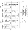
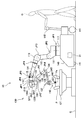
- FIG. 1 is a diagram showing an example of a configuration of a surgical system according to an embodiment.
- FIG. 2 is a side view showing an example of the configuration of the robot according to the embodiment.
- FIG. 3 is a perspective view showing an example of the configuration of the robot arm according to the embodiment.
- FIG. 4 is a diagram modeling the arm of FIG.
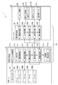
- FIG. 5 is a block diagram showing an example of the configuration of the control device of the surgical system according to the embodiment and its surroundings.
- FIG. 6 is a block diagram showing an example of the functional configuration of the control device according to the embodiment.
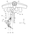
- FIG. 7 is a side view of the arm of FIG. 3 as viewed in the negative direction of the YA axis.
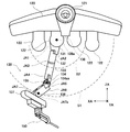
- FIG. 8 is a plan view of the arm of FIG.
- FIG. 9 is a side view showing another example of the restraint range in the same manner as in FIG. 7.
- FIG. 10 is a flowchart showing an example of the operation of the surgical system according to the embodiment.
- FIG. 11 is a diagram showing an example of the configuration of the surgical system according to the modified example in the same manner as in FIG.
- FIG. 12 is a side view showing an example of the configuration of the robot according to the modified example in the same manner as in FIG.
- the surgical robot according to one aspect of the present disclosure includes a plurality of robot arms having a plurality of degrees of freedom, a long arm base for holding the base ends of the plurality of robot arms, and the plurality of robot arms.
- Each of the plurality of robot arms includes a control device for controlling the operation, a base portion, a tip portion capable of holding a medical device, and a plurality of links connecting the base portion and the tip portion and connecting them to each other.
- the link adjacent to the base is connected to the base via a rotary joint, and at least one of the plurality of robot arms has at least seven degrees of freedom.
- the control device of the first link among the plurality of links when viewed from a direction parallel to the axial direction of the rotation axis of the rotary joint.
- the one robot arm is operated so that the first portion is located between the second portion of the base portion and the third portion of the tip portion.
- the robot arm having at least 7 degrees of freedom has at least one additional degree of freedom when the tip portion is set to the desired position and posture in the three-dimensional space. That is, the robot arm has a degree of freedom of redundancy. For example, when the robot arm is bent and operated, the first portion of the first link may project outward. However, the robot arm having a redundancy degree of freedom operates so that the first portion is located in the region between the second portion and the third portion, and the overhang of the first portion can be suppressed. Therefore, it is possible to prevent the robot arm from coming into contact with surrounding objects such as the adjacent robot arm during operation.
- the first link may have a bent shape, and the first portion may be a bent portion of the first link.
- the bent portion of the first link may project outward.
- the first link may be connected to the base via one or more of the links and may be connected to the tip of the robot via one or more of the links. ..
- the first link in the robot arm, there are two or more degrees of freedom between the first link and the base portion and between the first link and the tip portion, respectively.
- the first link or its periphery may project outward.
- the first link may be connected to the base portion via two or more said links, and may be connected to the tip portion via two or more said links. .. According to the above aspect, in the robot arm, the degree of freedom between the first link and the base portion and the degree of freedom between the first link and the tip portion can be increased.
- the control device in the one robot arm, has a first portion extending in a direction in which the first portion passes through the second portion and intersects the longitudinal direction of the arm base.
- the one robot arm may be operated so as to be located between the plane and the second plane extending in a direction passing through the third portion and intersecting the longitudinal direction.
- the first portion of the first link projects beyond the first plane or the second plane toward the adjacent robot arm. Is suppressed. Therefore, it is possible to effectively prevent the adjacent robot arms from coming into contact with each other.
- the first plane and the second plane may be parallel to each other or non-parallel to each other, and may be perpendicular to the longitudinal direction, for example.
- the first plane passes through the second portion and extends in a direction perpendicular to the longitudinal direction
- the second plane passes through the third portion and the longitudinal direction. May extend in the direction perpendicular to.
- the first plane, the second plane, and the region between the first plane and the second plane can be easily set with reference to the arm base. This simplifies the operation control of the robot arm that positions the first portion of the robot arm between the first plane and the second plane.
- the control device is described so that the first portion of the robot arm is located between the first plane and the second plane.
- One robot arm may be operated.
- the control device may operate one robot arm so that the first portion is located on a plane passing between the first plane and the second plane.
- the first portion has a reference point in the second portion and the second portion, and the third portion.
- the one robot arm may be operated so as to be located between the robot arm and the curved surface passing through the robot arm.
- the curved surface may be a spherical surface centered on the reference point, an axisymmetric curved surface centered on an axis passing through the reference point, or the like.
- the control device is such that the first portion is located between the second portion and the curved surface in the one robot arm.
- the robot arm may be operated.
- the control device may operate one robot arm so that the first portion is located on a curved surface passing between the second portion and the curved surface.
- the surgical system includes a plurality of robot arms having a plurality of degrees of freedom, a long arm base for holding the base ends of the plurality of robot arms, and the plurality of robot arms.
- An operation device for operating at least one of the robot arms and a control device for controlling the operation of the robot arm based on the operation by the operation device are provided, and at least one of the plurality of robot arms is provided.
- the robot arm has at least seven degrees of freedom, and each of the plurality of robot arms connects a base portion, a tip portion capable of holding a medical device, and the base portion and the tip portion are connected to each other.
- the links adjacent to the base are connected to the base via a rotary joint, and the control device is in a state in which the medical device passes through a preset remote center position.
- the robot arm is configured to move the robot arm based on the operation of the operating device under the operation restriction of moving the medical device while maintaining the control device, and the control device is operated by at least seven operating devices.
- the first part of the first link among the plurality of links is the second part of the base.
- the robot arm is operated so as to be located between the robot arm and the third portion of the tip portion.
- a control method includes a plurality of links, each of which includes a base, a tip capable of holding a medical device, and a plurality of links connecting the base and the tip to each other.
- the adjacent links are connected to the base via a rotary joint, and when viewed from a direction parallel to the axial direction of the rotary axis of the rotary joint in one robot arm having at least seven degrees of freedom.
- the one robot arm is operated so that the first portion of the first link among the plurality of links is located between the second portion of the base portion and the third portion of the tip portion. According to the above aspect, the same effect as that of the surgical robot according to one aspect of the present disclosure can be obtained.
- the first link may have a bent shape, and the first portion may be a bent portion of the first link.
- the first link may be connected to the base via one or more links and may be connected to the tip via one or more links. ..
- the first link may be connected to the base portion via two or more said links, and may be connected to the tip portion via two or more said links. ..
- the first portion passes through a first plane extending in a direction that passes through the second portion and intersects the longitudinal direction of the arm base, and passes through the third portion and the longitudinal direction.
- the one robot arm may be operated so as to be positioned between the robot arm and the second plane extending in the direction intersecting with the robot arm.
- the first plane passes through the second portion and extends in a direction perpendicular to the longitudinal direction
- the second plane passes through the third portion and the longitudinal direction. May extend in the direction perpendicular to.
- the one robot arm in the one robot arm, the one robot arm is operated so that the first portion is positioned between the first plane and the second plane. You may let me.
- the first part is a curved surface having a reference point in the second part and passing through the third part.
- the one robot arm may be operated so as to be located between them.
- the one robot arm in the one robot arm, the one robot arm is operated so that the first portion is located between the second portion and the curved surface. You may.
- FIG. 1 is a diagram showing an example of the configuration of the surgical system 1 according to the embodiment.
- the surgical system 1 includes a robot 10, a console 20, and a control device 30.
- the control device 30 includes a first control device 31 and a second control device 32.
- the surgical system 1 is a system in which a practitioner S such as a doctor performs a surgical operation such as endoscopic surgery on a patient using the robot 10, such as robot-assisted surgery and robot remote surgery. ..
- the robot 10 and the first control device 31 constitute a surgical robot.
- the surgical system 1 is a system using a master-slave robot 10.
- the console 20 constitutes a master machine, and the robot 10 constitutes a slave machine.
- the console 20 is arranged away from the robot 10, and the robot 10 is remotely controlled by the console 20 at the time of treatment.
- the practitioner S operates and operates the operation input device 210 of the console 20 to input a command to the operation input device 210, and the robot 10 performs an operation corresponding to the command to perform a surgical operation. it can.
- the operation input device 210 is an example of an operation device.
- the robot 10 constitutes an interface between the surgical system 1 and the patient.
- the robot 10 is placed beside the operating table on which the patient lies in the operating room.
- the robot 10 includes a positioner 110, an arm base 120, a plurality of arms 130, a base 140, and a first control device 31.
- the positioner 110 extends from the base 140 and connects the base 140 and the arm base 120.
- the positioner 110 is configured as a robot arm, and in the present embodiment, it is configured as a vertical articulated robot arm.
- the positioner 110 can freely move the position and posture of the arm base 120 with respect to the base 140 in the three-dimensional space.
- the configuration of the positioner 110 is not particularly limited as long as it supports the arm base 120, and may be, for example, a linear motion device, an elevating device, a fixing device, or the like.
- the fixing device may be a bracket or the like for fixing the arm base 120 to the ceiling, a wall, or the like.
- the configuration of the base 140 is not particularly limited as long as it can support the positioner 110, but in the present embodiment, it is configured as a movable carriage.
- the plurality of arms 130 are also called manipulator arms, and are detachably attached to and supported by a long arm base 120.
- the four arms 130A to 130D are arranged side by side on the arm base 120 in the first direction.
- the first direction is also the direction in which the arm base 120 extends and the longitudinal direction of the arm base 120.
- the fact that the arms 130A to 130D are arranged side by side in the first direction may mean that the base end portions of the arms 130A to 130D are arranged side by side in the first direction. In this case, the base end portions of the arms 130A to 130D may be arranged along the first direction as a whole.
- the fact that the base ends of the arms 130A to 130D are arranged side by side in the first direction means that the base ends of the arms 130A to 130D are arranged so as to be aligned along a line extending in the first direction. , At least some of the proximal ends may be displaced from the line, and the like.
- the quantity and arrangement of the arms 130 arranged on the arm base 120 may be any quantity and arrangement. In the following, when the four arms are distinguished and expressed, they may be expressed as "arms 130A to 130D", and when they are not distinguished, they may be expressed as "arms 130".
- Each of the plurality of arms 130 is configured as a robot arm, and in the present embodiment, it is configured as a vertical articulated robot arm.
- Each of the plurality of arms 130 can freely move the position and posture of the tip portion of the arm 130 with respect to the arm base 120 in the three-dimensional space.
- Each of the tips of the plurality of arms 130 is configured as an instrument holding portion capable of holding the surgical instrument 150, which is an example of a medical instrument.
- an endoscopic camera is held as a surgical instrument 150 at the tip of one of the plurality of arms 130, and an instrument such as a surgical instrument is held at the tip of the other arm 130. It is held as 150.
- Surgical instrument means an actual operated part that is inserted into a surgical site in the patient's abdominal cavity and can be driven from outside the abdominal cavity to perform the desired treatment or medical function of the target tissue at the surgical site.
- a surgical instrument comprises a pair of jaws.
- Surgical instruments may be surgical instruments such as forceps, grippers, scissors, staplers, needle holders, and electric scalpels.
- the surgical instrument may be an electrically driven device such as an electronic surgical electrode, a transducer, or a sensor.
- the surgical instrument may also be a nozzle that supplies fluid for inhalation, gas injection, irrigation, processing fluids, accessory introduction, biopsy removal and the like.
- the configuration of the endoscopic camera may include an objective lens, a light guide, and the like.
- the arm base 120 functions as a "hub” that serves as a base for a plurality of arms 130.
- the positioner 110 and the arm base 120 constitute a manipulator support 160 that movably supports a plurality of arms 130.
- each component is connected in a series from the positioner 110 to the surgical instrument 150.
- the end portion in the direction toward the connection portion between the positioner 110 and the base 140 may be referred to as a "base end portion”, and the end portion in the opposite direction may be referred to as a "tip portion”. ..
- FIG. 2 is a side view showing an example of the configuration of the robot 10 according to the embodiment.
- the base 140 includes wheels 141 and handles 142.
- the handle 142 is configured to be able to rotate together with the wheels 141.
- the practitioner S or the treatment assistant ⁇ can move the base 140 by grasping and pushing or pulling the handle 142, and can change the traveling direction of the base 140 by rotating the handle 142. it can.
- the positioner 110 includes the positioner links 111 to 116 and the base 117.
- the base 117 is detachably attached to the upper part of the base 140.
- Positioner links 111 to 116 are sequentially connected and extended from the base 117.
- the base end portion of the positioner link 111 is rotatably connected to the base portion 117 via a rotary joint JP1 about an axis in the vertical direction.
- the vertical direction is a direction perpendicular to the floor surface G on which the base 140 is arranged
- the horizontal direction is a direction parallel to the floor surface G.
- the base end portion of the positioner link 112 is rotatably connected to the tip end portion of the positioner link 111 via a rotary joint JP2 about an axis in the horizontal direction.
- the base end portion of the positioner link 113 is rotatably connected to the tip end portion of the positioner link 112 via a rotary joint JP3 about a horizontal axis.
- the base end portion of the positioner link 114 is twistably and rotatably connected to the tip end portion of the positioner link 113 via a rotary joint JP4.
- the twisting rotation axis may be an axis in the axial direction of the tip end portion of the positioner link 113.
- the base end portion of the positioner link 115 is rotatably connected to the tip end portion of the positioner link 114 via a rotary joint JP5 about an axis perpendicular to the axial direction of the tip end portion of the positioner link 114.
- the base end portion of the positioner link 116 is twistably and rotatably connected to the tip end portion of the positioner link 115 via a rotary joint JP6.
- the first attachment portion 121 of the arm base 120 is twistably and rotatably connected to the tip end portion of the positioner link 116 via the rotary joint JP7.
- the positioner 110 as described above is configured as a multi-axis joint arm having a plurality of degrees of freedom, specifically, a 7-axis joint arm having seven degrees of freedom.
- the arm base 120 includes one first mounting portion 121 and a plurality of second mounting portions 122.
- the first mounting portion 121 is arranged above the arm base 120 and constitutes a mechanical interface connected to the positioner link 116.
- Each of the plurality of second mounting portions 122 is arranged below the arm base 120 and constitutes a mechanical interface connected to the base end portion of the arm 130.
- four second mounting portions 122 are arranged.
- the arm base 120 can be twisted and rotated with respect to the positioner link 115 about the twisting rotation axis SP7 of the rotary joint JP7.
- FIG. 3 is a perspective view showing an example of the configuration of the arm 130 of the robot 10 according to the embodiment.
- FIG. 4 is a diagram modeling the arm 130 of FIG. Although one arm 130 is shown in FIGS. 3 and 4, the other three arms 130 have the same configuration as the illustrated arm 130.
- the arm 130 includes links 131-136, tip links 137, and base links 138.
- the base link 138 is detachably attached to the second attachment portion 122 of the arm base 120.
- the links 131 to 136 are sequentially connected and extended from the base link 138.
- the tip link 137 is connected to the link 136.
- the base link 138 is an example of the base of the robot arm, and the tip link 137 is an example of the tip of the robot arm.
- the base end portion of the link 131 is twistably and rotatably connected to the base link 138 via the rotary joint JA1.
- the link 131 has a shape bent so that the axial direction at the tip is inclined with respect to the axial direction at the proximal end, but the link 131 is not limited to this.
- the angle formed by the axial direction at the proximal end and the axial direction at the distal end may be 90 degrees or more and 180 degrees or less, specifically 140 degrees. You may.
- the rotary joint JA1 constitutes a torsion joint.
- the base end portion of the link 132 is rotatably connected to the tip end portion of the link 131 via the rotary joint JA2 about an axis perpendicular to the axial direction of the link 131 at the tip end portion.
- the link 132 is a linear link.
- the rotary joint JA2 constitutes a bending joint.
- the base end portion of the link 133 is twistably and rotatably connected to the tip end portion of the link 132 via the rotary joint JA3.
- the link 133 is a linear link.
- the rotary joint JA3 constitutes a twist joint.
- the base end portion of the link 134 is rotatably connected to the tip end portion of the link 133 via the rotary joint JA4 about an axis perpendicular to the axial direction of the link 133 at the tip end portion.
- the link 134 has an L-shaped bend so that the axial direction at the tip is perpendicular to the axial direction at the proximal end.
- the bent portion 134a of the link 134 corresponds to the elbow of the arm 130.
- the link 134 may be bent so that the axial direction at the tip is inclined with respect to the axial direction at the proximal end.
- the angle formed by the axial direction at the proximal end and the axial direction at the distal end may be 70 degrees or more and 110 degrees or less.
- the rotary joint JA4 constitutes a bending joint.
- the base end portion of the link 135 is twistably and rotatably connected to the tip end portion of the link 134 via the rotary joint JA5.
- the link 135 is a linear link.
- the rotary joint JA5 constitutes a twist joint.
- the base end portion of the link 136 is rotatably connected to the tip end portion of the link 135 via the rotary joint JA6 about an axis perpendicular to the axial direction of the link 135 at the tip end portion.
- Link 136 is a linear link.
- the rotary joint JA6 constitutes a bending joint.
- the base end of the tip link 137 is rotatably connected to the tip of the link 136 via the rotary joint JA7 about an axis perpendicular to the axial direction of the link 136 at the tip.
- the direction of the rotation axis of the rotary joint JA7 is a direction that intersects the direction of the rotation axis of the rotary joint JA6, and specifically, is a vertical direction.
- the rotary joint JA6 constitutes a bending joint.
- the arm 130 as described above is configured as a multi-axis joint arm having a plurality of degrees of freedom, specifically, a 7-axis joint arm having seven degrees of freedom.
- the arm 130 which is a 7-axis joint arm, has six degrees of freedom required when the tip link 137 is set to the desired position and posture in the three-dimensional space, and one additional degree of freedom, that is, redundant. Has a degree of freedom.
- the positions and postures of the links 131 to 136 are not uniquely determined.
- the tip link 137 includes a first connecting portion 137a, a translation unit 137b, a second connecting portion 137c, and a holder 137d.
- the first connecting portion 137a connects the rotary joint JA7 and the translational unit 137b.
- the second connecting portion 137c connects the translation unit 137b and the holder 137d on the opposite side of the translation unit 137b from the first connecting portion 137a.
- the translational unit 137b can change the relative positions of the connecting portions 137a and 137c in the directions D1A and D1B by moving at least one of the connecting portions 137a and 137c in the longitudinal directions D1A and D1B. It is configured as a double speed mechanism.
- the directions D1A and D1B are directions perpendicular to the direction of the rotation axis of the rotary joint JA7.
- the translational unit 137b includes a drive device 137e including a drive mechanism and a drive source.
- the drive mechanism is a mechanism that linearly moves at least one of the connecting portions 137a and 137c by converting and transmitting the driving force of the drive source.
- the configuration of the drive mechanism can be applied to the configuration of a known link mechanism, and may be, for example, a configuration using a belt and a pulley, a configuration including a ball screw structure, a configuration including a gear train, and the like.
- the drive source may include a motor powered by electric power, and in the present embodiment, includes a servomotor.
- the holder 137d is configured so that the surgical instrument 150 can be attached. As shown in FIGS. 3 and 4, when the instrument is attached to the holder 137d as a surgical instrument 150, the axis of the instrument extends, for example, in direction D1B.
- a coordinate system based on the arm base 120 is defined.
- This coordinate system is composed of an XA axis, a YA axis, and a ZA axis that are orthogonal to each other.
- the XA axis is an axis parallel to the alignment direction of the base links 138 of the four arms 130.
- the direction from the arm 130A to the arm 130D shown in FIG. 1 is the positive direction of the XA axis.
- the YA axis is an axis parallel to the connection surface (not shown) of the arm 130 with the base link 138 of the second mounting portion 122 in the direction perpendicular to the direction.
- the second mounting portion 122 has a hole (not shown) into which the base link 138 of the arm 130 is inserted, and the axis SA1 (see FIG. 2) of the hole is parallel to the YA axis.
- the axis SA1 is also parallel to the axis of rotation of the joint JA1.
- the direction from the second mounting portion 122 toward the base link 138 is the negative direction on the YA axis.
- the ZA axis is an axis perpendicular to the XA axis and the YA axis.
- the direction from the first mounting portion 121 to the second mounting portion 122 of the arm base 120 is the negative direction of the ZA axis.
- FIG. 5 is a block diagram showing an example of the configuration of the control device 30 of the surgical system 1 and its surroundings according to the embodiment.
- the positioners 110 are the servomotors MP1 to MP7 (denoted as “SM” in FIG. 5) and the rotation sensors EP1 to EP7 (in FIG. 5), which are encoders, for the joints JP1 to JP7, respectively. Notated as “EN").
- the servomotors MP1 to MP7 are motors that rotationally drive the joints JP1 to JP7, respectively.
- the rotation sensors EP1 to EP7 are sensors that detect the amount of rotation (for example, the angle of rotation) of the servomotors MP1 to MP7, respectively.
- a speed reducer (not shown) may be provided for each of the servomotors MP1 to MP7.
- Each arm 130 includes servomotors MA1 to MA7 and rotation sensors EA1 to EA7 in each of the joints JA1 to JA7.
- the servomotors MA1 to MA7 rotate and drive the joints JA1 to JA7, respectively.
- the rotation sensors EA1 to EA7 detect the amount of rotation of the servomotors MA1 to MA7, respectively.
- a speed reducer (not shown) may be provided for each of the servomotors MA1 to MA7.
- the tip link 137 of each arm 130 includes a servomotor M137b that translates the translation unit 137b and a rotation sensor E137b that detects the amount of rotation of the servomotor M137b.
- the servomotor M137b may be provided with a speed reducer (not shown).
- the rotation sensor is not limited to the encoder, and may be any sensor that can detect the rotation amount of the servomotor, the rotation amount of the joint, and the like.
- the control device 30 includes a first control device 31 and a second control device 32.
- the first control device 31 of the robot 10 controls the operation of the entire robot 10, and the second control device 32 of the console 20 controls the operation of the entire console 20.
- the first control device 31 and the second control device 32 are computer devices.
- the first control device 31 is communicably connected to the second control device 32.
- the first control device 31 operates the robot 10 in response to a command received by the console 20.
- the first control device 31 is a second control device for displaying the endoscope image of the endoscope camera on the console 20 and for causing the console 20 to perform an operation corresponding to the operation of the robot 10. Information and the like are transmitted to 32.
- the first control device 31 is electrically connected to the servomotors MA1 to MA7 via the drive circuits CA1 to CA7 (denoted as "SC" in FIG. 5).
- the first control device 31 is electrically connected to the servomotors MP1 to MP7 via the drive circuits CP1 to CP7, respectively.
- the first control device 31 is electrically connected to the servomotor M137b via the drive circuit C137b.
- the control device 30, and the drive circuits CA1 to CA7, CP1 to CP7, and C137b constitute a control unit 310.
- the drive circuits CA1 to CA7, CP1 to CP7, and C137b include an amplifier circuit and the like, and adjust the current value of the current supplied to the servomotors connected to each of them according to the command of the first control device 31.
- the first control device 31 is composed of an arithmetic unit having a processor, a memory, and the like.
- the arithmetic unit transmits / receives information, data, commands, and the like to and from other devices including the console 20.
- the arithmetic unit inputs detection signals from various sensors and outputs control signals to each control target.
- the memory is composed of a semiconductor memory such as a volatile memory and a non-volatile memory, a hard disk, and a storage device such as an SSD (Solid State Drive).
- the memory stores a program executed by an arithmetic unit, various fixed data, and the like.
- the function of the arithmetic unit is a computer system (not shown) consisting of a processor such as a CPU (Central Processing Unit), a volatile memory such as a RAM (Random Access Memory), and a non-volatile memory such as a ROM (Read-Only Memory). It may be realized. Some or all of the functions of the arithmetic unit may be realized by the CPU using the RAM as a work area to execute a program recorded in the ROM. A part or all of the functions of the arithmetic unit may be realized by the above computer system, or may be realized by a dedicated hardware circuit such as an electronic circuit or an integrated circuit, and may be realized by the above computer system and the hardware circuit. It may be realized by a combination.
- the first control device 31 may execute each process by centralized control by a single computer device, or may execute each process by distributed control by cooperation of a plurality of computer devices.
- Such a first control device 31 is composed of, for example, a microcontroller, an MPU (Micro Processing Unit), an LSI (Large Scale Integration), a system LSI, a PLC (Programmable Logic Controller), a logic circuit, or the like. You may.
- the plurality of functions of the first control device 31 may be realized by being individually integrated into one chip, or may be realized by being integrated into one chip so as to include a part or all of them. Further, each circuit may be a general-purpose circuit or a dedicated circuit.
- an FPGA Field Programmable Gate Array
- a reconfigurable processor that can reconfigure the connection and / or setting of circuit cells inside the LSI, or multiple functions for a specific application.
- An ASIC Application Specific Integrated Circuit
- ASIC Application Specific Integrated Circuit
- the console 20 is a device for operating the robot 10 by forming an interface between the surgical system 1 and the practitioner S.
- the console 20 is installed in the operating room beside the operating table, away from the operating table, or outside the operating room.
- the console 20 includes an operation input device 210 for receiving an input of a command from the practitioner S, a display device 220 for displaying an image captured by the endoscope camera, and a second control device 32.
- the endoscopic camera is attached to the robot 10 as a surgical instrument.
- the operation input device 210 includes a pair of left and right operation manipulators 211L and 211R and an operation pedal 212.
- the operation manipulators 211L and 211R are devices used for manually operating the robot 10.
- Each of the operation manipulators 211L and 211R is configured to receive an operation force from the practitioner S, and includes an operation unit (not shown) gripped by the practitioner S.
- the operation manipulators 211L and 211R are operation tools that receive a movement command of the position and posture of the endoscopic camera and the surgical instrument.
- the operation pedal 212 is an operation tool that receives commands such as zooming of an endoscope camera, switching of a control mode, and switching of an arm 130 associated with the operation manipulators 211L and 211R.
- the operation input device 210 further includes an operation tool that receives an input of a body cavity insertion command of a surgical instrument, an operation tool that receives an input of an arm return command, and the like.
- the operation input device 210 may have a drive mechanism (not shown) for applying a reaction force to the operation force of the practitioner S to the operation manipulators 211L and 211R.
- the practitioner S directly moves the operation parts of the operation manipulators 211L and 211R while confirming the affected part with the endoscopic image displayed on the display device 220, thereby causing the robot 10 to operate.
- the arm 130 of the robot 10 is associated with the operation manipulators 211L and 211R by, for example, operating the operation pedal 212, and the associated arm 130 operates according to the operation of the operation manipulators 211L and 211R.
- the second control device 32 is communicably connected to the first control device 31.
- the second control device 32 transmits the information, data, commands, and the like received by the operation input device 210 to the first control device 31.
- the second control device 32 controls the operation of the operation manipulators 211L and 211R and the like, the image display operation of the display device 220, and the like, based on the information, data, commands, and the like received from the first control device 31.
- a part or all of the functions of the second control device 32 may be realized by a computer system (not shown) including a CPU, RAM, ROM, etc., or by a dedicated hardware circuit such as an electronic circuit or an integrated circuit.
- the second control device 32 may execute each process by centralized control by a single computer device, or may execute each process by distributed control by cooperation of a plurality of computer devices.
- the second control device 32 and the first control device 31 may be included in a single computer device.
- FIG. 6 is a block diagram showing an example of the functional configuration of the control device 30 according to the embodiment.
- the second control device 32 of the console 20 has a functional configuration of an image processing unit 321, an input processing unit 322, an operation command unit 323, a position command unit 324, and an operation control unit 325. Include as an element.
- the functions of the above functional components are realized by a processor or the like. Not all of the above functional components are essential.
- the image processing unit 321 receives the image data captured by the endoscopic camera, which is one of the surgical instruments 150, from the first control device 31, and outputs the image data to the display device 220 for display.
- the image processing unit 321 may add conversion processing or the like to the image data and output it to the display device 220.
- the input processing unit 322 receives information, data, commands, etc. from the operation input device 210, processes them, and outputs them to the first control device 31 and / or the operation command unit 323. For example, the input processing unit 322 detects the amount of rotation of each joint from the detection values of the rotation sensors provided on each joint of the operation manipulators 211L and 211R, and the position and speed (movement speed) of the operation unit from the amount of rotation of each joint. ) Is calculated. The operation command unit 323 generates a movement command for commanding the position and speed of the robot 10 with respect to the positioner 110 and the arm 130 based on the position and speed of the operation unit calculated by the input processing unit 322.
- a force sensor for detecting the force applied to the operation manipulators 211L and 211R is provided, and the input processing unit 322 detects the force detection value such as the magnitude and direction of the force from the detection value of the force sensor and commands the operation.
- the unit 323 may generate a force command that commands the magnitude and direction of the force applied to the object by the arm 130 of the robot 10 based on the detected value of the force.
- the operation command unit 323 may generate a movement command using the acceleration corresponding to the detected value of the force.
- the operation command unit 323 outputs an operation operation command including the movement command and the force command to the first control device 31.
- the position command unit 324 receives the position command from the first control device 31.
- the position command includes a position and posture command corresponding to the position and posture of the positioner 110 and the arm 130 of the robot 10, and for example, a position and posture corresponding to the position and posture of each joint of the positioner 110 and the arm 130. Including the directive of.
- the position command unit 324 arranges the operation manipulators 211L and 211R so that the position and orientation of the operation unit of the operation manipulators 211L and 211R correspond to the tip link 137 of the arm 130 of the robot 10. Generates an operation position command that commands the position and posture of the operation unit of.
- the operation position command may include a force applied to the operation unit of the operation manipulators 211L and 211R.
- the position command unit 324 detects the position of each joint from the detection value of the rotation sensor provided on each joint of the operation manipulators 211L and 211R.
- the operation control unit 325 controls to supply a current to the servomotor of the corresponding joint based on the operation position command. As a result, the positions and postures of the operating portions of the operating manipulators 211L and 211R move in correspondence with the positions and postures of the arm 130 and the surgical instrument 150.
- the first control device 31 includes a positioner control unit 31a, an arm control unit 31b, and a storage unit 31c as functional components.
- the positioner control unit 31a controls the operation of the positioner 110
- the arm control unit 31b controls the operation of the arm 130 and the surgical instrument 150.
- Each function of the positioner control unit 31a and the arm control unit 31b is realized by a processor or the like, and the function of the storage unit 31c is realized by a memory.
- the positioner control unit 31a sets the positioner 110 and the arm base 120 at the preparation position stored in the storage unit 31c based on a command related to setting a preparation position input to an input device (not shown) provided in the robot 10. And control is performed so that the plurality of arms 130 move.
- the operation assistant O (may be the practitioner himself) moves the robot 10 near the operation table OT using the base 140.
- the positioner 110, the arm base 120, and the plurality of arms 130 are located at predetermined storage positions (not shown) set with respect to the base 140.
- the surgical assistant O inputs to the input device (not shown) of the robot 10 to select the preparation position according to the operation content of the patient P.
- the positioner control unit 31a reads out the information of the corresponding preparation position from the storage unit 31c, and operates the positioner 110 and the like so that the positioner 110, the arm base 120, and the plurality of arms 130 are located at the preparation position. It is also possible to individually adjust the positions of the positioner 110, the arm base 120, and the plurality of arms 130 from the prepared positions by using the input device of the robot 10.
- the first control device 31 does not accept the operation by the operation input device 210 until the positioner 110, the arm base 120, and the plurality of arms 130 move from the storage position to the preparation position. After the positioning to the preparation position is completed, the first control device 31 can accept the operation by the operation input device 210. At the time of treatment after the positioning to the preparation position is completed, the first control device 31 operates each arm 130 in response to a command from the operation input device 210 with the positioner 110 and the arm base 120 stationary in principle. The motion is controlled so as to appropriately change the position and posture of the surgical instrument 150.
- the arm control unit 31b includes an image acquisition unit 311, an information processing unit 312, an operation command unit 313, an axis position determination unit 314, and an operation control unit 315 as functional components. Not all of the above functional components are essential.
- the storage unit 31c can store various information, that is, can store the stored information, and can read the stored information.
- the storage unit 31c stores information on the prepared positions of the positioner 110, the arm base 120, and the plurality of arms 130.
- the storage unit 31c stores the remote center position for the treatment.
- the storage unit 31c stores the constraint condition 31ca used in the regulation mode.
- the storage unit 31c may store information on the surgical instrument 150 attached to the tip link 137 of each arm 130.
- the information on the surgical instrument 150 may include information such as the type, shape, dimensions, operating direction, and operating range of the surgical instrument 150.
- the storage unit 31c may store a program for realizing each function of the first control device 31.
- the remote center position is the reference position of the posture of the surgical instrument 150 during the operation.
- the first control device 31 may control the operation of the arm 130 while maintaining the state in which the instrument of the surgical instrument 150 passes through the remote center position during the operation.
- passing an instrument through a remote center position may include passing the instrument through a remote center position, and an extension of a center line such as the axis of the instrument passing through the remote center position.
- the first control device 31 operates while bending the arm 130 so as to change the instrument to various postures and insertion depths with respect to the remote center position. That is, the first control device 31 controls the operation of the arm 130 with the operation limitation.
- An example of a remote center position is position Pa on patient P shown in FIG.
- the position of the position Pa may be taught in the process of the operation assistant O preparing for the operation and may be stored in the storage unit 31c.
- the constraint condition 31ca is a condition for limiting the operating range of each arm 130. Specifically, the constraint condition 31ca includes the position of the constraint portion set on each arm 130 and the constraint range which is the range in which the constraint portion can be located when the arm 130 operates in association with each other. .. The constraint condition 31ca is a condition for the relative operation of each arm 130 with respect to the arm base 120, and is based on the arm base 120.
- the position of the restraint portion may be set to any position of the arm 130, but in the present embodiment, it is set to the bent portion 134a of the link 134. Specifically, the position of the restraint portion is set at the bending point 134aa (see FIGS. 3 and 4) of the axis of the link 134 in the bending portion 134a.
- the link 134 is an example of the first link, and the inflection point 134aa is an example of the first part.
- the robot 10 has the posture of each surgical instrument 150 and the posture of each surgical instrument 150 with respect to the remote center point Pa of the posture rotation of each surgical instrument 150 at the operation site of the patient P lying on the operating table OT.
- Each arm 130 is operated while being bent in order to change the insertion depth in various ways.
- the arm 130 bends at the link 134 located near the middle between the tip link 137 and the base link 138.
- the bent portion 134a (see FIG. 3) of the link 134 may greatly project upward and / or sideways and come into contact with the adjacent arm 130. Therefore, in the present embodiment, the bending point 134aa of the bending portion 134a of the link 134 is set as the restraint portion.
- the restraint range in each arm 130 is not a range determined based on the positional relationship between the arm 130 and the other arm 130, but a range determined based on the state of the arm 130.
- the restraint range is not a range fixed to the arm 130, but a range that fluctuates according to the state of the arm 130.
- the restraint range is the area between the portion of the base link 138 at a specific position and the portion of the tip link 137 at a specific position.
- the region may be a region when viewed from a direction parallel to the axial direction of the rotation axis of the rotary joint JA1.
- FIGS. 7 and 8 are side views and plan views of the arm 130 of FIG. 3 as viewed in the negative direction of the YA axis and the negative direction of the ZA axis, respectively.
- the portion of the base link 138 at a specific position is set at point 138a and the portion of the tip link 137 at a specific position is set at point JA7a.
- Point 138a is an intersection of the connecting surface between the base link 138 and the second mounting portion 122 and the axial center of the base link 138.
- the point JA7a is located at the connection portion between the tip link 137 and the link 136, and specifically, is the center point of the connection portion in the axial direction of the rotation axis of the rotary joint JA7 intersecting the first connecting portion 137a. ..
- the restraint range may be, for example, an intermediate position between the point 138a and the point JA7a.
- the "intermediate position" may include a central position between the two elements and a position near the central position.
- the base link 138 is an example of the second link
- the point 138a is an example of the second part
- the tip link 137 is an example of the third link
- the point JA7a is an example of the third part.
- the constraint range may be a three-dimensional region between a first plane extending in the direction passing through the point 138a and intersecting the XA axis and a second plane extending in the direction passing through the point JA7a and intersecting the XA axis. Good.
- the first plane and the second plane may be parallel to each other or non-parallel to each other.
- the axial direction of the XA axis is an example of the longitudinal direction of the arm base 120.
- the first plane may be a plane YZ8 perpendicular to the XA axis
- the second plane may be a plane YZ7 perpendicular to the XA axis.
- the plane YZ7 passes through the point JA7a and is parallel to the YAZA plane.
- Plane YZ8 passes through point 138a and is parallel to the YAZA plane. Therefore, even if the constraint range is a three-dimensional region between the first plane passing through the point 138a and extending in the direction perpendicular to the XA axis and the second plane extending through the point JA7a and extending in the direction perpendicular to the XA axis. Good.
- vertical As used herein and as claimed, “vertical”, “vertical”, “horizontal” and “parallel” are fully vertical, vertical, horizontal or parallel, and perfectly vertical, vertical, horizontal or parallel, respectively. It may include cases that can be regarded as substantially vertical, vertical, horizontal or parallel, including the vicinity of.
- the restraint range may be an intermediate position between the first plane and the second plane, and may be, for example, an intermediate position between the plane YZ7 and the plane YZ8.
- the constraint range may be a two-dimensional region on the third plane between the first plane and the second plane.
- the third plane may be parallel to at least one of the first plane and the second plane, or may be non-parallel to both.
- the third plane may be located between the first plane and the second plane.
- the third plane may be a plane YZE between the plane YZ7 and the plane YZ8.
- the plane YZE is parallel to the planes YZ7 and YZ8, but may be non-parallel.
- the position of the plane YZE may be between the plane YZ7 and the plane YZ8, and may be, for example, an intermediate position between the plane YZ7 and the plane YZ8.
- the constraint range may be a three-dimensional region between the point 138a and the first curved surface with the point 138a as a reference point.
- the first curved surface are a spherical surface such as a spherical surface and an elliptical spherical surface centered on the reference point, and an axisymmetric curved surface such as a rotating curved surface centered on an axis passing through the reference point.
- the reference points are the center, the focal point, and the like.
- the first curved surface may be a spherical surface S1.
- the spherical surface S1 is centered on the point 138a and passes through the point JA7a.
- the restraint range may be an intermediate position between the point 138a and the first curved surface, and may be, for example, an intermediate position between the point 138a and the spherical surface S1.
- FIG. 9 is a side view showing another example of the restraint range in the same manner as in FIG. 7.
- the constraint range may be a region on the second curved surface between the point 138a and the first curved surface.
- the shape of the second curved surface may be similar to or dissimilar to the first curved surface.
- the second curved surface may be located between the point 138a and the first curved surface.
- the second curved surface may be a spherical surface S2 between the point 138a and the spherical surface S1.
- the spherical surface S2 is centered on the point 138a, but may be centered on a point different from the point 138a.
- the position of the spherical surface S2 may be between the point 138a and the spherical surface S1, and may be, for example, an intermediate position between the point 138a and the spherical surface S1.
- the restraint range may be a region on a line segment connecting the point 138a and the point JA7a, or a region on a plane passing through the line segment and the YA axis or the rotation axis of the joint JA1.
- region on the plane and the region on the line segment shown above may include the plane and the region near the line segment such as the region within a predetermined distance from the line segment, respectively.
- the restraint range of the bending point 134aa is a range determined corresponding to the position of the base link 138 and the position of the tip link 137, and is a range that varies according to the position of the tip link 137. ..
- the constraint range will be described as a two-dimensional region on the plane YZE located in the middle between the plane YZ7 and the plane YZ8.
- the image acquisition unit 311 acquires the image data captured by the endoscopic camera of the surgical instrument 150 of the arm 130 and outputs it to the second control device 32.
- the information processing unit 312 receives an operation operation command including a movement command and a force command from the second control device 32, and outputs the operation operation command to the operation command unit 313.
- the information processing unit 312 may process the operation operation command and output it to the operation command unit 313.
- the information processing unit 312 reads information on the constraint condition 31ca of the arm 130 to be operated from the storage unit 31c based on a command or the like for executing the regulation mode received from the second control device 32, and outputs the information to the axis position determination unit 314. ..
- the information processing unit 312 may process the information of the constraint condition 31ca and output it to the axis position determining unit 314.
- the operation command unit 313 generates an operation command of the tip link 137 of the arm 130, which is the target of the operation operation command, from the operation operation command received from the information processing unit 312, and outputs the operation command to the shaft position determination unit 314.
- the operation command includes a position command and may further include a force command. A preset movement range limit, movement speed limit, or the like may be applied to the position command.
- the operation command unit 313 receives the operation information of the robot 10 from the operation control unit 315, generates an operation command of the operation unit of the operation manipulators 211L and 211R using the operation information, and outputs the operation command to the second control device 32. To do.
- the operation command includes a position command and may further include a force command.
- the operation command unit 313 may output the operation information of the robot 10 to the second control device 32 instead of the operation command.
- the position command of the tip link 137 may include a command indicating the position and posture of each joint of the tip link 137 and / or the arm 130, and a target value of the speed of the position and posture.
- the position and its speed may represent a position and a speed in a three-dimensional space
- the posture and its speed may represent a posture and a speed in a three-dimensional space.
- the position command may include the execution time of the position command.
- position means including at least a position in three-dimensional space of a position in three-dimensional space, a velocity of position, a posture and a velocity of posture.
- the force command includes a command indicating a target value of the magnitude and direction of the force applied to the object by the tip link 137.
- the direction of the force may represent the direction in the three-dimensional space.
- the force command may include the execution time of the force command.
- the position command of the operation unit of the operation manipulators 211L and 211R is the same as the position command of the tip link 137. It may include a command indicating a target value for speed. Further, the position command may include the execution time of the position command. The force command may include a command indicating a target value of the magnitude and direction of the force applied to the operation unit. The force command may include the execution time of the force command.
- the operation information of the robot 10 includes at least the operation data of the arm 130 among the operation data of the positioner 110 and the arm 130.
- the operation data of the arm 130 includes position data representing the positions of the tip link 137 and / or each joint of the arm 130 during operation.
- the operation data of the arm 130 may also include force data representing the force applied by the tip link 137 to the object.
- the operation data of the positioner 110 includes position data representing the positions of each joint and / or the arm base 120 of the positioner 110.
- the position data may include a position in the three-dimensional space and a posture in the three-dimensional space.
- the force data may include the magnitude of the force and the direction of the force in three-dimensional space.
- the position data and force data may be time series data associated with each position and the time of occurrence of each force.
- the operation information as information other than the operation data, imaging data of the object on which the tip link 137 acts, vibration data, impact data, optical data, sound data, temperature data, humidity data generated at the tip link 137, It may include pressure data such as pressure.
- the operation information handled in this embodiment includes at least operation data.
- the shaft position determining unit 314 determines the target value of the rotation amount (rotation angle) of each joint JA1 to JA7 of the arm 130 subject to the operation command based on the operation command received from the operation command unit 313, and sets the target value. Output to the operation control unit 315. That is, the shaft position determining unit 314 determines the rotational position of the joint shafts of the joints JA1 to JA7. Further, in the regulation mode, the shaft position determination unit 314 uses the constraint condition 31ca to determine the target value. The shaft position determining unit 314 may output the force command included in the operation command to the operation control unit 315.
- the shaft position determining unit 314 uses the three-dimensional position and three-dimensional posture target values of the tip link 137 and the three-dimensional position and 3 of the base link 138 included in the position command of the operation command.
- the target value of the amount of rotation (rotation angle) of the joints JA1 to JA7 is calculated by inversely transforming the detected value of the three-dimensional posture.
- the detected values of the three-dimensional position and the three-dimensional posture of the base link 138 are calculated from the three-dimensional position and the three-dimensional posture of the arm base 120.
- the first control device 31 detects the three-dimensional position and three-dimensional posture of the arm base 120 and / or the three-dimensional position and three-dimensional posture of the base link 138 of each arm 130. And may be retained.
- each arm 130 has seven joints.
- Each arm 130 has six degrees of freedom with six joints and one additional degree of freedom with one joint, which is required to target the three-dimensional position and three-dimensional posture of the tip link 137. .. Therefore, for one combination of the three-dimensional position of the tip link 137 and the target value of the three-dimensional posture, a plurality of combinations of the rotation amounts (rotation angles) of the joints JA1 to JA7 can be detected by calculation.
- the shaft position determining unit 314 selects an arbitrary combination from a plurality of combinations of the rotation amounts (rotation angles) of the joints JA1 to JA7, and the selected combination is used as the rotation amount (rotation) of the joints JA1 to JA7. Determine the target value of (angle). For example, the shaft position determining unit 314 may select the combination in which the amount of rotational movement of the joints JA1 to JA7 is the smallest. For example, regarding the operation of the arm 130 with reference to the remote center position, the shaft position determining unit 314 may use the information of the remote center position for the above selection. The shaft position determining unit 314 may select a combination in which the surgical instrument 150 passes through the remote center position from the combination of the rotation amounts of the joints JA1 to JA7.
- the shaft position determining unit 314 selects a combination of the rotation amounts (rotation angles) of the joints JA1 to JA7 in which the restraint portion of the arm 130 is located within the restraint range based on the constraint condition 31ca, and targets the combination. Determine the value.
- the shaft position determining portion 314 selects a combination in which the bending point 134aa of the bending portion 134a of the link 134 is located on the plane YZE.
- the plane YZE is located between the plane YZ7 passing through the point JA7a of the tip link 137 and perpendicular to the XA axis and the plane YZ8 passing through the point 138a of the base link 138 and perpendicular to the XA axis. It is parallel to YZ8.
- the shaft position determining unit 314 may use the information of the remote center position for the above selection. The shaft position determining unit 314 may select a combination in which the surgical instrument 150 passes through the remote center position from the combination of the rotation amounts of the joints JA1 to JA7.
- the motion control unit 315 generates and outputs an motion control command for controlling the supply of current to the servomotors MA1 to MA7 that drive the joints JA1 to JA7 of the arm 130 to be operated.
- the operation control unit 315 receives the detected values of the rotation amount and the current as feedback information from the rotation sensors EA1 to EA7 and the current sensor (not shown) of the servomotors MA1 to MA7, respectively.
- the operation control unit 315 may use the command value of the current supplied by the drive circuits CA1 to CA7 to the servomotors MA1 to MA7 as feedback information.
- the motion control unit 315 may receive the force detection value from the force sensor as feedback information.
- the motion control unit 315 detects the position of the joint from the detected value of the rotation amount of each joint JA1 to JA7.
- the motion control unit 315 determines the drive amount and drive of each joint JA1 to JA7 from the positions of the joints JA1 to JA7 and the target value of the rotation amount (rotation angle) of the joints JA1 to JA7 received from the shaft position determination unit 314. Determine the speed.
- the motion control unit 315 may determine the drive torque of each joint JA1 to JA7 from the force detection value from the force sensor and the force command of the motion command.
- the operation control unit 315 determines the current value for driving the servomotors MA1 to MA7 in accordance with the drive amount, the drive speed, and the drive torque, and determines the current of the current value. Generates an operation control command to be supplied to the servomotor and outputs it to the servomotor.
- the arm 130 operates in correspondence with the movement of the operation unit of the operation manipulators 211L and 211R.
- FIG. 10 is a flowchart showing an example of the operation of the surgical system 1 according to the embodiment.
- the practitioner S or the surgical assistant O inputs a command for designating the preparation position to the input device (not shown) of the robot 10 when performing the surgery on the patient P, and the second step is performed. 1
- the control device 31 receives the command.
- step S2 the first control device 31 operates the positioner 110 and the like so that the positioner 110, the arm base 120, and the plurality of arms 130 are positioned at the designated preparation positions.
- the first control device 31 shifts the robot 10 to the preparation position.
- each remote center position Pa is stored in the storage unit 31c by teaching the respective remote center positions when the surgical assistant O attaches the surgical instrument 150 to each of the arms 130A to 130D. ..
- step S3 the practitioner S or the practitioner O selects the arm to be operated by the operation manipulators 211L and 211R from the arms 130A to 130D by using the operation pedal 212 of the operation input device 210.
- the second control device 32 accepts the selection.
- the second control device 32 accepts the selection of the arm 130C and outputs a notification targeting the arm 130C to the first control device 31.
- the first control device 31 processes a command or the like from the second control device 32 as a command to the arm 130C.
- step S4 the practitioner S or the practitioner O inputs a command for executing the regulation mode to the operation input device 210.
- the second control device 32 receives the execution command of the regulation mode and outputs the command to the first control device 31.
- step S5 when the practitioner S inputs an operation to the operation units of the operation manipulators 211L and 211R, the second control device 32 generates an operation operation command corresponding to the operation and outputs the operation operation command to the first control device 31. To do.
- step S6 the first control device 31 generates an operation command for the tip link 137 of the arm 130C from the operation operation command.
- step S7 the first control device 31 applies the remote center position Pa stored in the storage unit 31c and the constraint condition 31ca to the operation command, so that the surgical instrument 150 passes through the remote center position Pa.
- the target value of the rotation amount (rotation angle) of the joints JA1 to JA7 is calculated so that the bending point 134aa of the bending portion 134a of the link 134 of the arm 130C is located on the plane YZE (see FIG. 7). That is, the first control device 31 calculates the target value of the rotation position of the joints JA1 to JA7 corresponding to the operation command and the constraint condition 31ca.
- step S8 the first control device 31 acquires the operation information of the arm 130C. Further, the first control device 31 uses the operation information as feedback information to generate an operation control command for operating the joints JA1 to JA7 so as to set the target value of the rotation position, and the servomotor of the arm 130C. Output to MA1 to MA7. That is, the first control device 31 outputs operation control commands for the joints JA1 to JA7 of the arm 130C.
- step S9 the arm 130C operates in accordance with the motion control command to position the inflection point 134aa of the link 134 on the plane YZE while maintaining the state in which the surgical instrument 150 passes through the remote center position Pa.
- the tip link 137 is moved to the target position and posture. That is, the arm 130C operates while positioning the restraint portion within the restraint range.
- step S10 the second control device 32 determines whether or not a termination command has been input to the operation input device 210 by the practitioner S or the treatment assistant O, and if there is a command input (step S10). Yes), the series of processes is completed, and if no input is made (No in step S10), the process returns to step S5.
- the end command may be a command to end the entire operation in the surgical system 1, a command to end the regulation mode, a command to switch the operation target from the arm 130C to another arm 130, or the like.
- the first control device 31 operates the arm 130C so that the bending point 134aa of the link 134, which is the restraint portion of the arm 130C, is located on the plane YZE which is the restraint range.
- the joints JA1 to JA7 and the links 131 to 136 of the arm 130C operate within a range in which the extension in the direction toward the adjacent arms 130B and 130D is suppressed. Therefore, it is possible to prevent the arm 130C from coming into contact with the arms 130B and 130D.
- the first control device 31 performs an operation of avoiding such contact of the arm 130C with the position of the point JA7a of the tip link 137 and the position of the point 138a of the base link 138 without using the states of the arms 130B and 130D. It can be realized based on the state of the arm 130C which is a state.
- the arm 130C is the operation target, but even if the other arm 130 is the operation target, the first control device 31 and the second control device 32 perform the same processing as in steps S3 to S10. ..
- the restraint range is on the plane YZE, but the first control device 31 and the second control device 32 perform the same processing as in steps S5 to S10 even if the restraint range is on the plane YZE.
- the first control device 31 calculates the target value of the rotation position of the joints JA1 to JA7 of the arm 130 using the constraint condition to be applied.
- the other constraint range may be the constraint range exemplified above.
- FIG. 11 is a diagram showing an example of the configuration of the surgical system 1 according to the modified example in the same manner as in FIG.
- FIG. 12 is a side view showing an example of the configuration of the robot 10 according to the modified example in the same manner as in FIG.
- the arm base 1200 of the robot 10 according to this modified example has a first mounting portion 1210 and a second mounting portion 1220.
- the positioner link 116 of the positioner 110 is connected to the first mounting portion 1210 via the rotary joint JP7, and extends from the first mounting portion 1210 in the direction of the twisting rotation shaft SP7 of the rotary joint JP7.
- the base link 138 of the arm 130 is connected to the second mounting portion 1220 and extends from the second mounting portion 1220 in the direction of the axis SA1 of the second mounting portion 1220.
- the direction in which the base link 138 extends from the second mounting portion 1220 is the same as the direction in which the positioner link 116 extends from the first mounting portion 1210. That is, the orientation of the mechanical interface portion of the first mounting portion 1210 is the same as the orientation of the mechanical interface portion of the second mounting portion 1220. Therefore, the arm 130 and the positioner 110 extend in the same direction from the arm base 1200.
- the axis SA1 and the rotation axis SP7 are parallel. This facilitates control of the movements of the arm 130 and the positioner 110.
- the arm base 120 is configured such that the arm 130 and the positioner 110 extend from the arm base 120 in substantially opposite directions.
- the orientation of the mechanical interface portion of the first mounting portion 121 of the arm base 120 is roughly opposite to the orientation of the mechanical interface portion of the second mounting portion 122.
- the first control device 31 controls the robot 10 provided with the arm base 1200 as described above in the same manner as in the embodiment. Specifically, the first control device 31 performs control using the same constraint conditions as in the embodiment.
- the point 134aa of the link 134 as the first part of the first link of the arm 130 is the point 138a of the base link 138 as the second part and the tip link 137 as the third part.
- the first part, the second part and the third part are not limited to the above.
- the first portion may be any portion of the link 134 and may be any portion of the other links 131-133 and 135-138.
- the second portion may be any portion of the base link 138 and may be any portion of any of the links 131-137.
- the third portion may be any portion of the tip link 137 and may be any portion of any of the links 131-136 and 138.
- the third portion may be located closer to the tip link 137 than the second portion, and the first portion may be between the second portion and the third portion.
- first part to the third part may be located at the joints JA1 to JA7.
- first portion of the link 134 may be located at the joint JA4 or JA5 adjacent to the link 134.
- the second portion of the base link 138 may be located at the joint JA1 adjacent to the base link 138.
- the third portion of the tip link 137 may be located at the joint JA7 adjacent to the tip link 137.
- first part of the first link eg, link 134) is in the part in the first link and in the joint adjacent to the first link (eg, joint JA4 and / or JA5). Can be targeted with parts.
- the second portion of the base (eg, base link 138) may cover a portion within the base and a portion within a joint adjacent to the base (eg, joint JA1).
- the third portion of the tip (eg, tip link 137) may cover a portion within the tip and a portion within a joint (eg, joint JA7) adjacent to the tip.
- the surgical system 1 is configured to include one robot 10 and one console 20, but is not limited thereto.
- the surgical system 1 may be configured to include one or more robots 10 and one or more consoles 20.
- the surgical system 1 may include a plurality of robots 10 and a plurality of consoles 20.
- the control device 30 may be configured to select and connect one of the plurality of robots 10 and one of the plurality of consoles 20 according to a command or the like received from at least one of the plurality of consoles 20.
- the technique of the present disclosure may be a control method.
- the control method according to the present disclosure includes a base, a tip capable of holding a medical device, and a plurality of links connecting the base and the tip and connecting them to each other, and a plurality of freedoms.
- the link is connected to the base via a rotary joint, and when viewed from a direction parallel to the axial direction of the rotary axis of the rotary joint in one robot arm having at least seven degrees of freedom.
- the one robot arm is operated so that the first portion of the first link among the plurality of links is located between the second portion of the base portion and the third portion of the tip portion.
- a control method may be realized by a circuit such as a CPU and an LSI, an IC card, a single module, or the like.
- the technique of the present disclosure may be a program for executing the above control method, or may be a non-temporary computer-readable recording medium in which the above program is recorded. Needless to say, the above program can be distributed via a transmission medium such as the Internet.
- the numbers such as the ordinal number and the quantity used above are all examples for concretely explaining the technology of the present disclosure, and the present disclosure is not limited to the illustrated numbers.
- the connection relationship between the components is illustrated for the purpose of specifically explaining the technique of the present disclosure, and the connection relationship for realizing the function of the present disclosure is not limited thereto.
- the division of blocks in the functional block diagram is an example, and even if a plurality of blocks are realized as one block, one block is divided into a plurality of blocks, and / or some functions are transferred to another block. Good.
- a single piece of hardware or software may process the functions of a plurality of blocks having similar functions in parallel or in a time division manner.
Landscapes
- Engineering & Computer Science (AREA)
- Health & Medical Sciences (AREA)
- Surgery (AREA)
- Robotics (AREA)
- Life Sciences & Earth Sciences (AREA)
- Heart & Thoracic Surgery (AREA)
- Nuclear Medicine, Radiotherapy & Molecular Imaging (AREA)
- Biomedical Technology (AREA)
- Medical Informatics (AREA)
- Molecular Biology (AREA)
- Animal Behavior & Ethology (AREA)
- General Health & Medical Sciences (AREA)
- Public Health (AREA)
- Veterinary Medicine (AREA)
- Mechanical Engineering (AREA)
- Oral & Maxillofacial Surgery (AREA)
- Pathology (AREA)
- Manipulator (AREA)
Priority Applications (4)
| Application Number | Priority Date | Filing Date | Title |
|---|---|---|---|
| EP20895085.7A EP4070919A4 (en) | 2019-12-05 | 2020-12-04 | Surgical robot, surgical system, and control method |
| US17/782,209 US12161437B2 (en) | 2019-12-05 | 2020-12-04 | Surgical robot, surgical system, and control method |
| JP2021562746A JP7369789B2 (ja) | 2019-12-05 | 2020-12-04 | 手術ロボット、手術システム及び制御方法 |
| US18/923,816 US20250041008A1 (en) | 2019-12-05 | 2024-10-23 | Surgical robot, surgical system, and control method |
Applications Claiming Priority (2)
| Application Number | Priority Date | Filing Date | Title |
|---|---|---|---|
| JP2019220692 | 2019-12-05 | ||
| JP2019-220692 | 2019-12-05 |
Related Child Applications (2)
| Application Number | Title | Priority Date | Filing Date |
|---|---|---|---|
| US17/782,209 A-371-Of-International US12161437B2 (en) | 2019-12-05 | 2020-12-04 | Surgical robot, surgical system, and control method |
| US18/923,816 Continuation US20250041008A1 (en) | 2019-12-05 | 2024-10-23 | Surgical robot, surgical system, and control method |
Publications (1)
| Publication Number | Publication Date |
|---|---|
| WO2021112228A1 true WO2021112228A1 (ja) | 2021-06-10 |
Family
ID=76222398
Family Applications (1)
| Application Number | Title | Priority Date | Filing Date |
|---|---|---|---|
| PCT/JP2020/045269 Ceased WO2021112228A1 (ja) | 2019-12-05 | 2020-12-04 | 手術ロボット、手術システム及び制御方法 |
Country Status (4)
| Country | Link |
|---|---|
| US (2) | US12161437B2 (https=) |
| EP (1) | EP4070919A4 (https=) |
| JP (1) | JP7369789B2 (https=) |
| WO (1) | WO2021112228A1 (https=) |
Cited By (2)
| Publication number | Priority date | Publication date | Assignee | Title |
|---|---|---|---|---|
| CN114145781A (zh) * | 2021-12-16 | 2022-03-08 | 北京智愈医疗科技有限公司 | 一种经腔道超声检查系统 |
| CN116965934A (zh) * | 2022-12-02 | 2023-10-31 | 深圳康诺思腾科技有限公司 | 机械臂、关节结构和手术机器人 |
Families Citing this family (2)
| Publication number | Priority date | Publication date | Assignee | Title |
|---|---|---|---|---|
| JP7393383B2 (ja) * | 2021-05-24 | 2023-12-06 | 川崎重工業株式会社 | 手術支援ロボットおよび多関節ロボットの作動方法 |
| WO2025209274A1 (zh) * | 2024-04-03 | 2025-10-09 | 深圳康诺思腾科技有限公司 | 患旁操作设备、手术机器人及外科医疗系统 |
Citations (3)
| Publication number | Priority date | Publication date | Assignee | Title |
|---|---|---|---|---|
| US20170020615A1 (en) * | 2015-07-23 | 2017-01-26 | Sri International | Robotic arm and robotic surgical system |
| JP2017104453A (ja) * | 2015-12-11 | 2017-06-15 | 川崎重工業株式会社 | 外科手術システム |
| JP2019529051A (ja) * | 2016-09-28 | 2019-10-17 | マイクロポート(シャンハイ)メドボット カンパニー,リミティッド | 手術ロボットシステム |
Family Cites Families (6)
| Publication number | Priority date | Publication date | Assignee | Title |
|---|---|---|---|---|
| JPH08107898A (ja) | 1994-10-12 | 1996-04-30 | Olympus Optical Co Ltd | 手術用マニピュレータ |
| JP6411999B2 (ja) * | 2012-06-01 | 2018-10-24 | インテュイティブ サージカル オペレーションズ, インコーポレイテッド | 手術器具マニピュレータの態様 |
| EP3119314B1 (en) * | 2014-03-17 | 2020-05-06 | Intuitive Surgical Operations, Inc. | System and method for breakaway clutching in an articulated arm |
| EP3868326B1 (en) * | 2014-03-17 | 2025-12-31 | Intuitive Surgical Operations, Inc. | TOOL POSITIONING SYSTEM |
| JP6800058B2 (ja) * | 2017-03-23 | 2020-12-16 | 株式会社メディカロイド | 患者載置用テーブルの移動方法 |
| AU2019441247A1 (en) * | 2019-04-15 | 2021-10-14 | Covidien Lp | System and method for aligning a surgical robotic arm |
-
2020
- 2020-12-04 WO PCT/JP2020/045269 patent/WO2021112228A1/ja not_active Ceased
- 2020-12-04 EP EP20895085.7A patent/EP4070919A4/en active Pending
- 2020-12-04 JP JP2021562746A patent/JP7369789B2/ja active Active
- 2020-12-04 US US17/782,209 patent/US12161437B2/en active Active
-
2024
- 2024-10-23 US US18/923,816 patent/US20250041008A1/en active Pending
Patent Citations (3)
| Publication number | Priority date | Publication date | Assignee | Title |
|---|---|---|---|---|
| US20170020615A1 (en) * | 2015-07-23 | 2017-01-26 | Sri International | Robotic arm and robotic surgical system |
| JP2017104453A (ja) * | 2015-12-11 | 2017-06-15 | 川崎重工業株式会社 | 外科手術システム |
| JP2019529051A (ja) * | 2016-09-28 | 2019-10-17 | マイクロポート(シャンハイ)メドボット カンパニー,リミティッド | 手術ロボットシステム |
Non-Patent Citations (1)
| Title |
|---|
| See also references of EP4070919A4 |
Cited By (2)
| Publication number | Priority date | Publication date | Assignee | Title |
|---|---|---|---|---|
| CN114145781A (zh) * | 2021-12-16 | 2022-03-08 | 北京智愈医疗科技有限公司 | 一种经腔道超声检查系统 |
| CN116965934A (zh) * | 2022-12-02 | 2023-10-31 | 深圳康诺思腾科技有限公司 | 机械臂、关节结构和手术机器人 |
Also Published As
| Publication number | Publication date |
|---|---|
| US20250041008A1 (en) | 2025-02-06 |
| JPWO2021112228A1 (https=) | 2021-06-10 |
| EP4070919A4 (en) | 2023-12-27 |
| US12161437B2 (en) | 2024-12-10 |
| JP7369789B2 (ja) | 2023-10-26 |
| EP4070919A1 (en) | 2022-10-12 |
| US20230012535A1 (en) | 2023-01-19 |
Similar Documents
| Publication | Publication Date | Title |
|---|---|---|
| JP7316762B2 (ja) | 外科手術システム及び外科手術システムの制御方法 | |
| JP7369789B2 (ja) | 手術ロボット、手術システム及び制御方法 | |
| CN113520599B (zh) | 手术辅助机器人和手术辅助机器人的定位方法 | |
| CN111084661A (zh) | 手术辅助装置及其控制方法、以及记录介质 | |
| JP7402894B2 (ja) | 外科手術システム及び外科手術マニピュレータアームの制御方法 | |
| CN113558767B (zh) | 手术辅助机器人以及枢转位置设定方法 | |
| CN108882969B (zh) | 外科手术系统 | |
| JP7748501B2 (ja) | 手術支援ロボットおよび手術支援ロボットシステム | |
| JP2020065910A (ja) | 手術支援装置 | |
| JP2020065904A (ja) | 手術支援装置 | |
| JP7265916B2 (ja) | 外科手術システム及び外科手術システムの制御方法 | |
| US12171513B2 (en) | Surgical system and patient-side apparatus | |
| JPH08215205A (ja) | 医療用マニピュレータ | |
| JP6820389B2 (ja) | 外科手術システムの患者側装置および外科手術システム | |
| JP2020120764A (ja) | 手術支援装置 | |
| CN114378819A (zh) | 一种消化内镜微创手术机器人主从手控制方法和装置 | |
| JP2026074346A (ja) | 手術支援システム、ピボット位置設定方法およびプログラム | |
| JP2025152921A (ja) | 手術ロボットシステムおよびその制御方法 | |
| WO2025206298A1 (ja) | 手術ロボットシステムおよびその制御方法 | |
| WO2022168510A1 (ja) | 手術支援ロボット、手術支援システムおよび手術支援ロボットの制御方法 | |
| WO2025206297A1 (ja) | 手術ロボットシステムおよびその制御方法 | |
| JP2025154561A (ja) | 支援システムおよび支援方法 | |
| JP2025152923A (ja) | 手術ロボットシステムおよびその制御方法 | |
| JP2023061245A (ja) | 手術支援ロボット |
Legal Events
| Date | Code | Title | Description |
|---|---|---|---|
| 121 | Ep: the epo has been informed by wipo that ep was designated in this application |
Ref document number: 20895085 Country of ref document: EP Kind code of ref document: A1 |
|
| ENP | Entry into the national phase |
Ref document number: 2021562746 Country of ref document: JP Kind code of ref document: A |
|
| NENP | Non-entry into the national phase |
Ref country code: DE |
|
| ENP | Entry into the national phase |
Ref document number: 2020895085 Country of ref document: EP Effective date: 20220705 |