WO2021112148A1 - Cleaning device - Google Patents
Cleaning device Download PDFInfo
- Publication number
- WO2021112148A1 WO2021112148A1 PCT/JP2020/044939 JP2020044939W WO2021112148A1 WO 2021112148 A1 WO2021112148 A1 WO 2021112148A1 JP 2020044939 W JP2020044939 W JP 2020044939W WO 2021112148 A1 WO2021112148 A1 WO 2021112148A1
- Authority
- WO
- WIPO (PCT)
- Prior art keywords
- cleaning
- brush
- roller
- cleaning brush
- foreign matter
- Prior art date
Links
- 238000004140 cleaning Methods 0.000 title claims abstract description 413
- 229910052751 metal Inorganic materials 0.000 claims abstract description 43
- 239000002184 metal Substances 0.000 claims abstract description 43
- 230000002093 peripheral effect Effects 0.000 claims description 41
- 238000011144 upstream manufacturing Methods 0.000 claims description 16
- 239000000428 dust Substances 0.000 description 70
- 239000000463 material Substances 0.000 description 17
- 238000007667 floating Methods 0.000 description 14
- 239000004020 conductor Substances 0.000 description 13
- 229920002635 polyurethane Polymers 0.000 description 13
- 239000004814 polyurethane Substances 0.000 description 13
- 238000000034 method Methods 0.000 description 10
- 238000007599 discharging Methods 0.000 description 9
- 230000007246 mechanism Effects 0.000 description 9
- 229920005989 resin Polymers 0.000 description 8
- 239000011347 resin Substances 0.000 description 8
- 230000000694 effects Effects 0.000 description 7
- 239000000126 substance Substances 0.000 description 7
- 229910052782 aluminium Inorganic materials 0.000 description 6
- XAGFODPZIPBFFR-UHFFFAOYSA-N aluminium Chemical compound [Al] XAGFODPZIPBFFR-UHFFFAOYSA-N 0.000 description 6
- 230000005684 electric field Effects 0.000 description 6
- 229920000728 polyester Polymers 0.000 description 6
- NIXOWILDQLNWCW-UHFFFAOYSA-N acrylic acid group Chemical group C(C=C)(=O)O NIXOWILDQLNWCW-UHFFFAOYSA-N 0.000 description 5
- 238000004519 manufacturing process Methods 0.000 description 5
- 239000007769 metal material Substances 0.000 description 5
- 229910001220 stainless steel Inorganic materials 0.000 description 5
- 239000010935 stainless steel Substances 0.000 description 5
- 239000011737 fluorine Substances 0.000 description 4
- 229910052731 fluorine Inorganic materials 0.000 description 4
- 239000011521 glass Substances 0.000 description 4
- -1 polypropylene Polymers 0.000 description 4
- 229920003002 synthetic resin Polymers 0.000 description 4
- 239000000057 synthetic resin Substances 0.000 description 4
- 229920002803 thermoplastic polyurethane Polymers 0.000 description 4
- YCKRFDGAMUMZLT-UHFFFAOYSA-N Fluorine atom Chemical compound [F] YCKRFDGAMUMZLT-UHFFFAOYSA-N 0.000 description 3
- 239000004433 Thermoplastic polyurethane Substances 0.000 description 3
- 239000000835 fiber Substances 0.000 description 3
- 239000010408 film Substances 0.000 description 3
- 238000007747 plating Methods 0.000 description 3
- 229920000178 Acrylic resin Polymers 0.000 description 2
- 239000004925 Acrylic resin Substances 0.000 description 2
- RYGMFSIKBFXOCR-UHFFFAOYSA-N Copper Chemical compound [Cu] RYGMFSIKBFXOCR-UHFFFAOYSA-N 0.000 description 2
- JOYRKODLDBILNP-UHFFFAOYSA-N Ethyl urethane Chemical compound CCOC(N)=O JOYRKODLDBILNP-UHFFFAOYSA-N 0.000 description 2
- PXHVJJICTQNCMI-UHFFFAOYSA-N Nickel Chemical compound [Ni] PXHVJJICTQNCMI-UHFFFAOYSA-N 0.000 description 2
- 206010040954 Skin wrinkling Diseases 0.000 description 2
- 230000008901 benefit Effects 0.000 description 2
- 150000001875 compounds Chemical class 0.000 description 2
- 229920001577 copolymer Polymers 0.000 description 2
- 239000000203 mixture Substances 0.000 description 2
- 239000000843 powder Substances 0.000 description 2
- 238000001179 sorption measurement Methods 0.000 description 2
- 239000000758 substrate Substances 0.000 description 2
- 125000000022 2-aminoethyl group Chemical group [H]C([*])([H])C([H])([H])N([H])[H] 0.000 description 1
- 229920002799 BoPET Polymers 0.000 description 1
- OKTJSMMVPCPJKN-UHFFFAOYSA-N Carbon Chemical compound [C] OKTJSMMVPCPJKN-UHFFFAOYSA-N 0.000 description 1
- 229920000049 Carbon (fiber) Polymers 0.000 description 1
- 239000004952 Polyamide Substances 0.000 description 1
- 239000004721 Polyphenylene oxide Substances 0.000 description 1
- 239000004743 Polypropylene Substances 0.000 description 1
- 238000005299 abrasion Methods 0.000 description 1
- 229920006243 acrylic copolymer Polymers 0.000 description 1
- 238000005452 bending Methods 0.000 description 1
- 229920005549 butyl rubber Polymers 0.000 description 1
- 229910052799 carbon Inorganic materials 0.000 description 1
- 239000006229 carbon black Substances 0.000 description 1
- 239000004917 carbon fiber Substances 0.000 description 1
- 239000011248 coating agent Substances 0.000 description 1
- 238000011109 contamination Methods 0.000 description 1
- 229910052802 copper Inorganic materials 0.000 description 1
- 239000010949 copper Substances 0.000 description 1
- 238000005260 corrosion Methods 0.000 description 1
- 230000007797 corrosion Effects 0.000 description 1
- 238000001514 detection method Methods 0.000 description 1
- 238000009826 distribution Methods 0.000 description 1
- 230000002708 enhancing effect Effects 0.000 description 1
- 239000011888 foil Substances 0.000 description 1
- PCHJSUWPFVWCPO-UHFFFAOYSA-N gold Chemical compound [Au] PCHJSUWPFVWCPO-UHFFFAOYSA-N 0.000 description 1
- 239000010931 gold Substances 0.000 description 1
- 229910052737 gold Inorganic materials 0.000 description 1
- VNWKTOKETHGBQD-UHFFFAOYSA-N methane Chemical compound C VNWKTOKETHGBQD-UHFFFAOYSA-N 0.000 description 1
- 230000004048 modification Effects 0.000 description 1
- 238000012986 modification Methods 0.000 description 1
- 229910052759 nickel Inorganic materials 0.000 description 1
- 238000005457 optimization Methods 0.000 description 1
- 239000004014 plasticizer Substances 0.000 description 1
- 229920002647 polyamide Polymers 0.000 description 1
- 229920000570 polyether Polymers 0.000 description 1
- 229920001155 polypropylene Polymers 0.000 description 1
- 229920001343 polytetrafluoroethylene Polymers 0.000 description 1
- 230000009467 reduction Effects 0.000 description 1
- 238000007790 scraping Methods 0.000 description 1
- 229920002050 silicone resin Polymers 0.000 description 1
- 238000010408 sweeping Methods 0.000 description 1
- BFKJFAAPBSQJPD-UHFFFAOYSA-N tetrafluoroethene Chemical group FC(F)=C(F)F BFKJFAAPBSQJPD-UHFFFAOYSA-N 0.000 description 1
- 229920001187 thermosetting polymer Polymers 0.000 description 1
- 239000010409 thin film Substances 0.000 description 1
- 238000004804 winding Methods 0.000 description 1
- 239000002759 woven fabric Substances 0.000 description 1
- 230000037303 wrinkles Effects 0.000 description 1
Images


Classifications
-
- B08B1/20—
-
- B08B1/32—
-
- B—PERFORMING OPERATIONS; TRANSPORTING
- B08—CLEANING
- B08B—CLEANING IN GENERAL; PREVENTION OF FOULING IN GENERAL
- B08B11/00—Cleaning flexible or delicate articles by methods or apparatus specially adapted thereto
-
- B—PERFORMING OPERATIONS; TRANSPORTING
- B08—CLEANING
- B08B—CLEANING IN GENERAL; PREVENTION OF FOULING IN GENERAL
- B08B6/00—Cleaning by electrostatic means
Definitions
- the present invention relates to a cleaning device.
- a cleaning roller having a charged surface and a roller-shaped cleaning brush are provided, and the direction of rotation at the contact portion of the cleaning roller with the surface of the object is relative to the transport direction of the object.
- a cleaning device is known in which the direction of rotation at the contact portion of the cleaning brush with the surface of the object is opposite to the transport direction of the object (see Japanese Patent Application Laid-Open No. 2016-215155). ).
- the conventional cleaning device In this conventional cleaning device, a relatively large millimeter-sized foreign matter can be effectively removed with a cleaning brush, and fine foreign matter can be effectively removed by adsorbing the surface to the surface of the cleaning roller in a charged state. Therefore, the conventional cleaning device can remove fine foreign matter as well as relatively large foreign matter of millimeter size.
- burrs may occur on both edges of the surface during the manufacturing process itself. Since a part of this burr is connected to the object, it is difficult to sufficiently remove it with the above-mentioned conventional cleaning device.
- the present invention has been made in view of such inconvenience, and an object of the present invention is to provide a cleaning device capable of effectively removing burrs generated on the surface of an object.
- a cleaning brush having a columnar core metal and a brush portion having a plurality of bristles provided on the peripheral surface of the core metal is effective, and the present invention has been found.
- Brown is generally partly connected to the object and the other part is floating away from the object.
- the present inventors effectively remove the burrs because the tips of the brush enter between the floating portion of the burrs and the object and scrape the burrs to remove the burrs from the object. I'm guessing it can be done.
- the cleaning device of the present invention is a cleaning device that cleans at least one surface of a sheet-shaped object to be conveyed, and includes a pair of cleaning brushes that are rotationally driven in contact with the one surface and the above.
- the other surface of the object is provided with a pair of rollers that are in contact with the pair of cleaning brushes facing each other, and the pair of cleaning brushes is formed of a columnar core metal and a plurality of bristles. It has a brush portion provided on the peripheral surface, and is rotationally driven so that the brush portion comes into contact with at least both side edges of the one surface, and is one of the pair of cleaning brushes.
- the direction of rotation at the contact portion with the surface of the object is forward with respect to the transport direction of the object, and the direction of rotation of the other cleaning brush at the contact portion with the one surface is the transport direction of the object. On the other hand, it is in the opposite direction.
- a cleaning brush that is rotationally driven in the forward direction removes burrs that are separated from the object on the upstream side in the transport direction
- a cleaning brush that is rotationally driven in the reverse direction removes burrs that are separated from the object. It is possible to remove burrs that are floating away from the surface. Therefore, since the cleaning device can remove burrs that are floating in any direction and separated from each other, burrs generated on the surface of the object can be effectively removed.
- the peripheral speed of one of the cleaning brushes is larger than the transport speed of the object, and the speed difference is preferably 1 m / min or more and 30 m / min or less.
- the amount of pushing of the pair of cleaning brushes against one of the surfaces is preferably 0.3 mm or more and 3 mm or less.
- the pair of cleaning brushes are rotationally driven and the contact portion vibrates in the direction of the rotation axis.
- the cleaning brush By vibrating the cleaning brush in the direction of the rotation axis in this way, it becomes easier to scrape burrs that are floating away from the object along the direction perpendicular to the transport direction, so that burrs can be removed more effectively. it can.
- a cleaning roller that comes into contact with the one surface in a charged state is provided, and the rotation direction of the cleaning roller at the contact portion with the one surface is forward with respect to the transport direction of the object. It is preferable that the one cleaning brush, the other cleaning brush, and the cleaning roller are arranged in this order from the upstream side in the transport direction, and the other cleaning brush comes into contact with each other over the width direction of the one surface.
- the "pushing amount” is a value obtained by subtracting the distance between the rotation axis of the cleaning brush and the surface of the object from the radius of the cleaning brush. If this number is positive, the bristles of the cleaning brush come into contact with the surface of the object.
- the cleaning device of the present invention can effectively remove burrs generated on the surface of an object.
- FIG. 1st cleaning unit of the cleaning apparatus of FIG. It is a schematic top view which shows the roller structure of the cleaning apparatus different from FIG.
- FIG. 2nd cleaning brush and the cleaning roller of FIG. It is a schematic side view which shows the structure of the 2nd cleaning brush and the cleaning roller of FIG. 4 when the transportation of an object is stopped.
- the cleaning device 1 shown in FIGS. 1 and 2 is a cleaning device that cleans both sides of the sheet-shaped object S to be conveyed.
- the cleaning device 1 includes a first cleaning unit 10 and a second cleaning unit 20.
- the object S to be cleaned by the cleaning device 1 is not particularly limited as long as it is in the form of a sheet.
- examples of the object S include an FPD glass substrate, a printed circuit board on which electronic components are mounted, a resin thin plate, a metal thin plate, a film material, and a laminated product thereof.
- the object S as shown in FIG. 1, one having a burr S1 is preferable, and a resin thin plate, a metal thin plate, or a laminated one thereof can be mentioned.
- the cleaning device 1 is particularly effective when the burr S1 is a whiskers.
- the whiskers have a thread-like or long plate-like shape, and the length direction thereof easily coincides with the length direction (transportation direction) of the object S, and occurs mainly on both side edges of the surface of the object S. easy. Further, one end of the beard burr is connected to the surface of the object S, and the other end is floating from the surface of the object S. Therefore, as shown in FIGS. 1 and 2, the burr S1 is mainly connected to both side edges of the object S along the transport direction (arrow directions in FIGS. 1 and 2), and the upstream side is connected to the object S and is downstream.
- a mustache burr S1a whose side is floating from the surface of the object S (hereinafter, also referred to as "reverse direction mustache burr S1a”) and a mustache burr S1b whose downstream side is connected to the object S along the transport direction and whose upstream side is floating from the surface of the object S.
- forward direction mustache burr S1b it is also referred to as “forward direction mustache burr S1b”.
- the case where the object S has burrs S1 (reverse burrs S1a and forward burrs S1b) as shown in FIGS. 1 and 2 will be described as an example, but the object S of the cleaning device 1 has the burrs. It does not mean that you are limited to what you have.
- the object S may be a film-like object having flexibility or a plate-like object having low flexibility.
- the average thickness of the object S is not particularly limited, but the lower limit of the average thickness of the object S is, for example, preferably 20 ⁇ m, more preferably 50 ⁇ m. If the average thickness of the object S is less than the above lower limit, it may be difficult to transport the object S.
- the object S is transported at a constant speed in the transport directions shown in FIGS. 1 and 2 by a drive device (not shown) installed outside the cleaning device 1.
- the transport speed of the object S is not particularly limited, but the lower limit of the transport speed of the object S is preferably 5 m / min, more preferably 10 m / min.
- the upper limit of the transport speed of the object S is preferably 30 m / min, more preferably 20 m / min. If the transport speed of the object S is less than the above lower limit, the cleaning efficiency and thus the productivity of the object S may decrease. On the contrary, if the transport speed of the object S exceeds the above upper limit, the power consumption may become too large.
- the object S may have tabs (not shown) protruding in the width direction on both side edges. This tab moves while being sandwiched between guides described later when the object S passes through the first cleaning unit 10 and the second cleaning unit 20. As a result, the object S is fixed, and both sides of the object S can be effectively cleaned.
- the tab configuration of the object S is not particularly limited as long as it can be guided by the guide, but for example, a configuration in which a plurality of rectangular protrusions are discretely arranged in a plan view can be used.
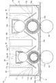
- the first cleaning unit 10 includes a pair of cleaning brushes (first cleaning brush 11 and second cleaning brush 12) and a pair of rollers (first roller 13 and second roller 14). ..
- the first cleaning unit 10 includes a dust collecting roller 15 (first dust collecting roller 15a and a second dust collecting roller 15b), a scraper 16 (first scraper 16a and a second scraper 16b), and a foreign matter guiding plate 17 (first dust collecting roller 16a).
- a foreign matter guiding plate 17a and a second foreign matter guiding plate 17b), a foreign matter discharging portion 18, and a frame 19 for storing these are provided.
- the pair of cleaning brushes (first cleaning brush 11 and second cleaning brush 12) have, for example, a roller shape and are rotationally driven.
- the rotation direction of the first cleaning brush 11 at the contact portion with one surface of the object S is opposite to the transport direction of the object S, and the contact portion with the one surface of the second cleaning brush 12
- the direction of rotation is forward with respect to the transport direction of the object S. That is, in the cleaning device 1, the rotation direction of one of the pair of cleaning brushes (second cleaning brush 12) at the contact portion with the one surface is relative to the transport direction of the object S. It is a forward direction, and the direction of rotation of the other cleaning brush (first cleaning brush 11) at the contact portion with the one surface is opposite to the transport direction of the object S.
- the first cleaning brush 11 has a columnar core metal 11a and a brush portion 11b formed of a plurality of bristles and provided on the peripheral surface of the core metal 11a.
- the brush portion 11b may be configured by directly planting a plurality of bristles on the peripheral surface of the core metal 11a or by winding a brushed woven fabric around the surface of the core metal 11a.
- the rotation direction of the first cleaning brush 11 at the contact portion with one of the above surfaces is opposite to the transport direction of the object S, it is possible to mainly remove the reverse whiskers S1a. That is, since the rotation direction of the first cleaning brush 11 is opposite, the bristles of the brush portion 11b come into contact with the burr S1 from the downstream side in the transport direction. Since the downstream side of the reverse beard burr S1a floats from the surface of the object S along the transport direction, the bristles of the brush portion 11b easily enter the gap and push up the reverse beard burr S1a upward. S1a can be stripped from the object S.
- the core metal 11a is made of a conductive material.
- the conductive material include metal materials such as stainless steel and aluminum.
- the central axis of the core metal 11a is the rotation axis of the first cleaning brush 11.
- the rotation axis is substantially perpendicular to the transport direction and substantially parallel to one surface of the object S. Note that “substantially parallel to the surface” means that the angle formed by the surface is within ⁇ 10 °, and “approximately perpendicular to the transport direction” means that the angle formed by the transport direction is 90 ° ⁇ 10. It means that it is within °.
- the diameter (average diameter) of the core metal 11a is appropriately determined from the strength of the bristles of the brush portion 11b and the like, and is, for example, 6 mm or more and 16 mm or less.
- the "average” refers to the average value of the amounts measured at any 10 points.
- the length of the core metal 11a is a length that can cover the distribution of the object S of the burr S1 to be removed in the width direction.
- the brush portion 11b is provided on at least both side edges of one of the above surfaces.
- the first cleaning brush 11 can come into contact with at least both side edges of one surface of the object S.
- the region where the brush portion 11b contacts one surface of the object S is preferably a range that covers at least 1/5 in the width direction from at least both side edges of the one surface in a plan view, and 1/3. It is more preferable to cover the area. By covering the above range, it is possible to suppress the omission of removal of the burr S1 while reducing the contact resistance between the brush portion 11b and one surface of the object S.
- the brush portion 11b may be provided over the entire length of the core metal 11a. In this case, since the first cleaning brush 11 comes into contact with the object S over the width direction of one surface, the dust removing effect on the surface of the object S can be obtained.
- the bristles forming the brush portion 11b are preferably those to which foreign matter is easily physically attached, and examples thereof include fibers made of synthetic resin.
- the synthetic resin include polyester, polyamide, polypropylene, and fluorine-containing resins such as tetrafluorethylene, chlorotrifluorylene, polytetrafluorethylene, and polychlorotrifluorethylene.
- polyester is preferable because it is easy to secure appropriate rigidity and the removal efficiency of burr S1 is high.
- the bristles forming the brush portion 11b are preferably those capable of being charged with an electric charge capable of adsorbing foreign substances by the force of an electric field, and are synthetic containing a conductive material such as carbon black, carbon fiber, metal powder, or metal whisker. Resin fibers can be preferably used.
- the bristles forming the brush portion 11b By using the bristles forming the brush portion 11b to which foreign matter easily adheres, the burr S1 removed from one surface of the object S can be recovered as it is, so that the burr S1 becomes the foreign matter again on the object S. Adhesion can be prevented. It is preferable that the first cleaning brush 11 is charged and used, but the first cleaning brush 11 does not necessarily have to be charged because foreign matter adheres to the brush portion 11b even if the force of the electric field does not act.
- the cross-sectional shape of the hair of the brush portion 11b is not particularly limited, and as the brush portion 11b, for example, a brush portion 11b having a circular cross-sectional shape, an elliptical shape, a star shape, or the like can be used. Further, the outer shape of the brush portion 11b is not particularly limited, and the brush portion 11b may have, for example, a linear outer shape, a wavy curve shape, a shape formed by combining a curved line and a straight line, or the like. it can. From the viewpoint of enhancing the effect of removing the burr S1 of the brush portion 11b, as the bristles forming the brush portion 11b, for example, those having a star-shaped cross section can be preferably used.
- the upper limit of the average length of the bristles of the brush portion 11b is preferably 15 mm, more preferably 10 mm. If the average length of the bristles of the brush portion 11b is less than the above lower limit, the bristles may not sufficiently enter the gap between the bristles S1 and the surface of the object S, and burrs S1 that cannot be removed may occur. On the contrary, if the average length of the bristles of the brush portion 11b exceeds the above upper limit, the flexibility of the bristles becomes too large and the burr S1 may not be scraped off.
- the lower limit of the rigidity index of the bristles of the brush portion 11b 20 is preferable, and 30 is more preferable.
- the upper limit of the rigidity index of the bristles of the brush portion 11b 100 is preferable, and 75 is more preferable. If the rigidity index of the bristles of the brush portion 11b is less than the above lower limit, the removal efficiency of the burr S1 may decrease. On the contrary, if the rigidity index of the bristles of the brush portion 11b exceeds the above upper limit, the surface of the object S may be damaged.
- the lower limit of the fineness of the hair of the brush portion 11b 4D is preferable, and 5D is more preferable.
- the upper limit of the fineness of the hair of the brush portion 11b 13D is preferable, and 10D is more preferable. If the fineness of the bristles of the brush portion 11b is less than the above lower limit, the rigidity may be insufficient, and the removal efficiency of the burr S1 and the removal efficiency of foreign matter may decrease. On the contrary, if the fineness of the bristles of the brush portion 11b exceeds the above upper limit, the surface of the object S may be damaged.
- the lower limit of the diameter of the first cleaning brush 11 (the sum of the diameter of the core metal 11a and the average length of the bristles of the brush portion 11b) is preferably 15 mm, more preferably 20 mm.
- the upper limit of the diameter of the first cleaning brush 11 is preferably 50 mm, more preferably 45 mm. If the diameter of the first cleaning brush 11 is less than the above lower limit, the bristles of the brush portion 11b cannot be sufficiently secured, and burrs S1 that cannot be removed may occur. On the contrary, if the diameter of the first cleaning brush 11 exceeds the above upper limit, the cleaning device 1 may become unnecessarily large.
- the lower limit of the pushing amount of the first cleaning brush 11 As the lower limit of the pushing amount of the first cleaning brush 11, 0.3 mm is preferable, and 0.4 mm is more preferable.
- the upper limit of the pushing amount of the first cleaning brush 11 3 mm is preferable, and 2 mm is more preferable. If the pushing amount of the first cleaning brush 11 is less than the above lower limit, the burr S1 may not be sufficiently scraped off. On the contrary, when the pushing amount of the first cleaning brush 11 exceeds the above upper limit, the bristles strongly hit one surface of the object S, so that the bristles move backward (downstream in the transport direction) before the bristles abut on the burr S1. It bends to the side).
- the pushing amount can be controlled by adjusting the distance between the rotation shaft of the first cleaning brush 11 and the rotation shaft of the first roller 13, which will be described later, according to the thickness of the object S.
- the upper limit of the peripheral speed of the first cleaning brush 11 is preferably 30 m / min, more preferably 15 m / min. If the peripheral speed of the first cleaning brush 11 is less than the above lower limit, the burr S1 on one surface of the object S may not be sufficiently scraped off. On the contrary, when the peripheral speed of the first cleaning brush 11 exceeds the above upper limit, the frictional force between the brush portion 11b and one surface of the object S becomes large, so that the transport speed of the object S cannot be maintained. There is a risk.
- the first cleaning brush 11 is rotationally driven and the contact portion vibrates in the direction of the rotation axis.
- the contact portion vibrates in the direction of the rotation axis.
- the lower limit of its amplitude is preferably 1 mm, more preferably 2 mm.
- the upper limit of the amplitude 10 mm is preferable, and 5 mm is more preferable. If the amplitude is less than the above lower limit, the effect of improving the removal of the burr S1 due to vibration may not be sufficiently obtained. On the contrary, when the amplitude exceeds the upper limit, it is necessary to move the first cleaning brush 11 at high speed in the width direction of the object S in order to obtain a desired vibration cycle, and the manufacturing cost of the cleaning device 1 is reduced. There is a risk that it will be unnecessarily large and that power consumption will increase unnecessarily.
- the vibration cycle also depends on the transport speed of the object S, but when the time required for the object S to move 1 m is t (seconds), the upper limit of the vibration cycle is preferably 1/3 t. , 1 / 5t is more preferable. If the vibration cycle is less than the above lower limit, the angle of contact with the burr S1 from an oblique direction becomes shallow, so that the effect of improving the removal of the burr S1 by vibration may not be sufficiently obtained.
- the lower limit of the vibration cycle is not particularly limited, but may be, for example, 1 / 20t.
- vibration cycle is less than the above lower limit, it becomes necessary to move the first cleaning brush 11 at high speed in the width direction of the object S, which may unnecessarily increase the manufacturing cost of the cleaning device 1 and increase power consumption. It may increase unnecessarily.
- the second cleaning brush 12 has a columnar core metal 12a and a brush portion 12b formed of a plurality of bristles and provided on the peripheral surface of the core metal 12a.
- the second cleaning brush 12 may be arranged so as to be in contact with the first cleaning brush 11, but the second cleaning brush 12 is arranged apart from the first cleaning brush 11, that is, the pair of cleaning brushes are separated from each other. It is preferable that they are arranged.
- the forward whiskers S1b can be mainly removed. That is, since the rotation direction of the second cleaning brush 12 is the forward direction, the bristles of the brush portion 12b come into contact with the burr S1 from the upstream side in the transport direction. Since the upstream side of the forward beard burr S1b floats from the surface of the object S along the transport direction, the bristles of the brush portion 12b easily enter the gap and push up the forward beard burr S1b upward. S1b can be stripped from the object S.
- the configuration of the second cleaning brush 12 will be described. Since the second cleaning brush 12 has a different rotation direction from the first cleaning brush 11, it can be configured in the same manner as the first cleaning brush 11 except that its peripheral speed is different and the configuration due to this difference is different. Hereinafter, the above differences will be described, and detailed description of the same configuration as that of the first cleaning brush 11 will be omitted.
- the peripheral speed of the second cleaning brush 12 is preferably higher than the transport speed of the object S.
- the lower limit of the speed difference between the peripheral speed of the second cleaning brush 12 and the transport speed of the object S is preferably 1 m / min, more preferably 3 m / min.
- the upper limit of the speed difference is preferably 30 m / min, more preferably 15 m / min. If the speed difference is less than the lower limit, the burr S1 on one surface of the object S may not be sufficiently scraped off. On the contrary, if the speed difference exceeds the upper limit, the frictional force between the brush portion 12b and one surface of the object S becomes large, so that the transport speed of the object S may not be maintained.
- the absolute value of the peripheral speed is different between the first cleaning brush 11 and the second cleaning brush 12, and the peripheral speed of the second cleaning brush 12 is generally set to be larger.
- a method of increasing the peripheral speed of the second cleaning brush 12 there is a method of increasing the rotation speed of the second cleaning brush 12 by making the first cleaning brush 11 and the second cleaning brush 12 have the same diameter.
- the same type of cleaning brush can be used as the first cleaning brush 11 and the second cleaning brush 12, the cost reduction and simplification of the production of the cleaning device 1 are promoted.
- FIG. 3 a method in which the diameter of the second cleaning brush 12 is made larger than the diameter of the first cleaning brush 11 can be mentioned.
- the ratio of the diameters may be determined so as to be a ratio of the peripheral speeds so that a desired peripheral speed can be obtained at the same rotation speed.
- operation control can be facilitated.
- the pair of rollers comes into contact with the other surface of the object S so as to face the pair of cleaning brushes.
- the first roller 13 contacts the other surface of the object S so as to face the first cleaning brush 11
- the second roller 14 faces the other surface of the object S and faces the second cleaning brush 12. And make contact.
- the first roller 13 is rotatably arranged at a position substantially parallel to and facing the first cleaning brush 11.
- the first roller 13 is carried around with the transportation of the object S. That is, the first roller 13 rotates due to the frictional force between the first roller 13 and the object S as the object S moves, and the rotation axis of the first roller 13 itself is not rotationally driven.
- Part or all of the first roller 13 is made of a conductive material.
- a conductive material include a metal material such as stainless steel and aluminum, and a conductive resin.
- the hardness of the first roller 13 that holds the object S on the lower surface thereof is high.
- the conductive material a metal material whose hardness can be easily secured is preferable.
- the first roller 13 may be formed only of such a conductive material, and the outer peripheral surface of the core metal formed of such a conductive material is covered with an insulating layer such as a synthetic resin. May be good.
- the first roller 13 When the first cleaning brush 11 is charged and used, the first roller 13 is grounded. As a result, the adsorption effect of the electric field force of the first cleaning brush 11 is promoted, and the burr S1 removed from one surface of the object S is easily attracted to the first cleaning brush 11.
- the first roller 13 may be configured so that no voltage is applied to the first roller 13.
- the length of the first roller 13 may be the same as the length of the core metal 11a of the first cleaning brush 11.
- the diameter of the first roller 13 is not particularly limited, but may be the same as the diameter of the first cleaning brush 11.
- the second roller 14 is rotatably arranged at a position substantially parallel to and facing the second cleaning brush 12.
- the second roller 14 can be configured in the same manner as the first roller 13, detailed description thereof will be omitted.
- the diameter of the second cleaning brush 12 is larger than the diameter of the first cleaning brush 11, the diameter of the second roller 14 is preferably the same as the diameter of the first roller 13.
- the dust collecting roller 15 is arranged substantially parallel to the pair of cleaning brushes so that the surface of the dust collecting roller 15 comes into contact with the outer peripheral side of the pair of cleaning brushes while being charged and rotationally driven. Further, the scraper 16 scrapes the foreign matter adhering to the surface of the dust collecting roller 15, and the foreign matter guiding plate 17 guides the scraped foreign matter to the foreign matter discharging section 18 via the foreign matter collecting section 19a described later.
- the foreign matter discharging unit 18 discharges the foreign matter to the outside of the first cleaning unit 10.
- the dust collecting roller 15, the scraper 16, the foreign matter guiding plate 17, and the foreign matter discharging portion 18 are housed inside the frame 19 together with a pair of cleaning brushes and a pair of rollers.
- the frame 19 is substantially orthogonal to the transport direction of the object S, and is disposed substantially parallel to the transport direction and substantially perpendicular to the surface of the object S with the front plate and the rear plate arranged before and after the transport direction. It has a pair of side plates and a top plate arranged substantially parallel to the surface of the object S. The top plate is connected to the upper ends of the pair of side plates, the front plate, and the rear plate.
- the first dust collecting roller 15a that contacts the outer peripheral side of the first cleaning brush 11 and the second dust collecting roller 15b that contacts the outer peripheral side of the second cleaning brush 12 are independent.
- a pair of scrapers 16 (a pair of first scrapers 16a and a pair of second scrapers 16b) are provided on each dust collecting roller 15.
- each scraper 16 is provided with a foreign matter guide plate 17 (a pair of first foreign matter guide plates 17a and a pair of second foreign matter guide plates 17b).
- the first dust collecting roller 15a, the first scraper 16a, and the first foreign matter guiding plate 17a will be described, but the second dust collecting roller 15b, the second scraper 16b, and the second foreign matter guiding plate 17b can have the same configuration. ..
- a conductive material is used as the material of the first dust collecting roller 15a.
- a conductive material include metal materials such as stainless steel and aluminum.
- a corrosion-resistant plating treatment such as nickel plating or gold plating on the surface of the first dust collecting roller 15a.
- the surface of the first dust collecting roller 15a has a higher potential than the outer peripheral side of the first cleaning brush 11, so that foreign matter adhering to the first cleaning brush 11 is adsorbed on the surface of the first dust collecting roller 15a, and the first dust collecting roller 15a is first. Foreign matter adhering to the cleaning brush 11 moves to the first dust collecting roller 15a. Thereby, the work of removing the foreign matter accumulated on the first cleaning brush 11 can be omitted or reduced.
- the rotation direction of the first dust collecting roller 15a may be any direction.
- the first scraper 16a is, for example, a rectangular plate, and has a portion that can come into contact with the surface of the first dust collecting roller 15a in the axial direction.
- a pair of first scrapers 16a are provided on both sides of the first dust collecting roller 15a in a side view, but the number of first scrapers 16a may be one.
- the long side of the first scraper 16a in contact with the surface of the first dust collecting roller 15a is referred to as a tip portion.
- the first scraper 16a is formed of an elastic body made of a synthetic resin such as thermosetting polyurethane. As the first dust collecting roller 15a rotates, the foreign matter adhering to the surface of the first dust collecting roller 15a is scraped off by the tip of the first scraper 16a that comes into contact with the surface of the first dust collecting roller 15a. As a result, the surface of the first dust collecting roller 15a is in a clean state with foreign matter removed.
- the first foreign matter guiding plate 17a is, for example, a rectangular plate, so that one surface faces upward from directly below the first scraper 16a to directly above the foreign matter collecting portion 19a provided on the frame 19 described later. It is arranged. Further, the first foreign matter guiding plate 17a is provided so as to be inclined so that the foreign matter collecting portion 19a side is lowered. With this arrangement, the foreign matter scraped off by the first scraper 16a falls on the surface of the first foreign matter guiding plate 17a and is guided directly above the foreign matter collecting portion 19a by the inclination of the first foreign matter guiding plate 17a. It falls to 19a and is collected.
- a dust collecting roller 15, a scraper 16 and a foreign matter guiding plate 17 are independently provided for a pair of cleaning brushes, but one pair of dust collecting rollers 15 is provided.
- the cleaning brush By arranging the cleaning brush so as to be in contact with the outer peripheral side of the cleaning brush, the dust collecting roller 15, the scraper 16 and the foreign matter guiding plate 17 can be shared.
- a foreign matter collecting portion 19a is provided at the lower part of the front plate and the rear plate of the frame 19 and the lower center of the frame 19.
- the foreign matter collecting unit 19a is configured as a part of the frame 19, but it can also be configured independently of the frame 19.
- the foreign matter collecting unit 19a is provided directly below the lower end of the foreign matter guiding plate 17 provided at an angle, and collects foreign matter falling from the foreign matter guiding plate 17.
- One foreign matter collecting unit 19a may be provided for one foreign matter guiding plate 17, but two or more foreign matter collecting portions 19a like the foreign matter collecting portion 19a at the lower center of the frame 19 in FIG. It may be provided so as to collect the foreign matter from the foreign matter guide plate 17.
- the shape of the foreign matter collecting portion 19a is not particularly limited, but it is preferably dish-shaped, that is, a flat plate having an upwardly bent end. By making the foreign matter collecting portion 19a into a dish shape, it is possible to prevent the collected foreign matter from being dissipated to the outside of the foreign matter collecting portion 19a.
- the foreign matter discharging unit 18 discharges the foreign matter collected by the foreign matter collecting unit 19a to the outside of the first cleaning unit 10.
- the foreign matter discharging unit 18 is provided in each foreign matter collecting unit 19a.
- the foreign matter discharging unit 18 is configured as a suction duct, and the foreign matter collected in the foreign matter collecting unit 19a is sucked through the suction duct by a suction device (not shown), and the first foreign matter is sucked. Discharge to the outside of the cleaning unit 10.
- the configuration of the foreign matter discharging unit 18 is not limited to the suction duct, and other configurations such as a configuration for sweeping out with a brush or the like can be adopted.
- the second cleaning unit 20 includes a pair of cleaning brushes (third cleaning brush 21 and fourth cleaning brush 22), a pair of rollers (third roller 23 and fourth roller 24), a dust collecting roller, a scraper, and a frame. And.
- the pair of cleaning brushes are formed of a columnar core metal and a plurality of bristles, like the pair of cleaning brushes of the first cleaning unit 10, and are formed of the core metal. It has a brush portion provided on the peripheral surface of the object S, and is rotationally driven so that the brush portion contacts at least both side edges of the other surface of the object S. Further, the direction of rotation of the third cleaning brush 21 at the contact portion with the other surface is opposite to the transport direction of the object S, and at the contact portion of the fourth cleaning brush 22 with the other surface. The rotation direction of the object S is forward with respect to the transport direction of the object S.
- the rotation direction of one of the pair of cleaning brushes (fourth cleaning brush 22) at the contact portion with the other surface is relative to the transport direction of the object S. It is a forward direction, and the direction of rotation of the other cleaning brush (third cleaning brush 21) at the contact portion with the other surface is opposite to the transport direction of the object S.
- the pair of rollers comes into contact with one surface of the object S facing the pair of cleaning brushes. Specifically, the third roller 23 contacts one surface of the object S facing the third cleaning brush 21, and the fourth roller 24 faces one surface of the object S facing the fourth cleaning brush 22. And make contact.
- the second cleaning unit 20 can be configured in the same manner as the first cleaning unit 10 except that the surfaces of the objects S that the pair of cleaning brushes and the pair of rollers come into contact with are different as described above, other detailed description will be omitted. ..
- the cleaning device 1 preferably includes a guide (not shown).
- the guide may have a first guide attached to the first cleaning unit 10 and a second guide attached to the second cleaning unit 20.
- the first guide is composed of a pair of strips arranged on both sides of the object S along the transport direction, for example.
- Each strip has two plates facing each other, and the tab of the object S can pass between the two plates.
- a metal plate such as stainless steel can be used as the plate.
- the widths of the above two plates are adjusted in the vertical direction so that they both come into contact with the tabs at least at the downstream end in the transport direction.
- the pair of strips may be continuous in the width direction of the object S, but are not arranged at a position where at least the pair of cleaning brushes and the pair of rollers come into contact with the object S.
- the first cleaning unit 10 has the first guide and the second cleaning unit 20 has the second guide has been described, but the first guide and the second guide are integrated into one. It can also be provided as a guide.
- the cleaning device 1 removes burrs S1 whose upstream side in the transport direction is floating away from the object S by the second cleaning brush 12 and the fourth cleaning brush 22 which are rotationally driven in the forward direction, and is rotationally driven in the opposite direction.
- the first cleaning brush 11 and the third cleaning brush 21 can remove the burr S1 whose downstream side in the transport direction is floating away from the object S. Therefore, since the cleaning device 1 can remove the burrs S1 that are floating and separated in any direction, the burrs S1 generated on both sides of the object S can be effectively removed.
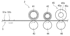
- the cleaning device 2 shown in FIGS. 4 and 5 is a cleaning device that cleans one surface of the sheet-shaped object S to be conveyed.
- the cleaning device 2 has a pair of cleaning brushes (first cleaning brush 41 and a second cleaning brush 42) that are rotationally driven in contact with the one surface, and the pair of cleanings on the other surface of the object S.
- a pair of rollers (first roller 43 and second roller 44) that come into contact with the brush, a cleaning roller 45 that comes into contact with one of the above surfaces while the surface is charged, and the other surface of the object S.
- a third roller 46 that faces the cleaning roller 45 and comes into contact with the cleaning roller 45 is provided.
- the rotation direction of one of the pair of cleaning brushes (first cleaning brush 41) at the contact portion with the one surface is forward with respect to the transport direction of the object S.
- the direction of rotation of the other cleaning brush (second cleaning brush 42) at the contact portion with the one surface is opposite to the transport direction of the object S.
- the rotation direction of the cleaning roller 45 at the contact portion with the one surface is the forward direction with respect to the transport direction of the object S.
- the one cleaning brush (first cleaning brush 41), the other cleaning brush (second cleaning brush 42), and the cleaning roller 45 are arranged in this order from the upstream side in the transport direction. .. Further, the other cleaning brush (second cleaning brush 42) is in contact with the other cleaning brush in the width direction of the one surface.
- the first cleaning brush 41 can be configured in the same manner as the second cleaning brush 12 in the first embodiment, detailed description thereof will be omitted. Since the rotation direction of the first cleaning brush 41 at the contact portion with one of the above surfaces is the forward direction with respect to the transport direction of the object S, the forward whisker burr S1b can be mainly removed.
- the second cleaning brush 42 is in contact with the object S over the width direction of one surface as described above. Except for this point, the second cleaning brush 42 can be configured in the same manner as the first cleaning brush 11 in the first embodiment, and therefore detailed description of other configurations will be omitted.
- the second cleaning brush 42 is rotationally driven so that the rotation direction at the contact portion with one surface of the object S is opposite to the transport direction of the object S. Therefore, the second cleaning brush 42 can mainly remove the reverse whiskers S1a. Further, since the second cleaning brush 42 is in contact with the object S over the width direction of one surface, when it comes into contact with one surface of the object S, it adheres to one surface of the object S. Foreign matter is aroused. Since the relatively large millimeter-sized foreign matter is scraped up by the above-mentioned scraping, the relatively large millimeter-sized foreign matter is effectively removed from one surface of the object S by the second cleaning brush 42.
- the cleaning roller 45 has a cylindrical core metal 45a, a cylindrical inner layer portion 45b that covers the peripheral surface of the core metal 45a, and a thin film cylindrical portion that covers the outer peripheral surface of the inner layer portion 45b. It has an outer layer portion 45c.
- the core metal 45a is made of a conductive material.
- the conductive material include metal materials such as stainless steel and aluminum.
- the central axis of the core metal 45a serves as the rotation axis of the cleaning roller 45 and is rotatably arranged.
- the rotation axis is substantially perpendicular to the transport direction and substantially parallel to one surface of the object S.
- the cleaning roller 45 rotates with the transportation of the object S. That is, the cleaning roller 45 rotates due to the frictional force between the cleaning roller 45 and the object S as the object S moves, and the rotation shaft of the cleaning roller 45 is not rotationally driven.
- an elastic member having conductivity As the material of the inner layer portion 45b, an elastic member having conductivity is used. Examples of such an elastic member include polyester-based urethane containing carbon.
- the material of the outer layer portion 45c may be any material that can be charged with a charge that adsorbs foreign matter adhering to one surface of the object S by the force of an electric field, and examples thereof include polyurethanes such as acrylic mixed polyurethane and fluorine mixed polyurethane. Be done.
- polyurethanes such as acrylic mixed polyurethane and fluorine mixed polyurethane.
- the acrylic mixed polyurethane contains polyester polyurethane or polyether polyurethane as a main component, and further consists of (1) thermoplastic polyurethane and silicon-acrylic copolymer resin, and (2) acrylic resin (for example, methacrylate-methyl methacrylate copolymer). It means a graft compound (a graft compound in which an aminoethyl group is grafted on the main chain) and a thermoplastic polyurethane, or (3) a mixture containing an acrylic resin, polyurethane and a fluorine-based surface coating agent.
- the "main component” is a component having the highest content, for example, a component contained in an amount of 50% by mass or more.
- the above-mentioned fluorine-mixed polyurethane is mainly composed of polyurethane, and means a mixture containing thermoplastic polyurethane and urethane / fluorine copolymer.
- the lower limit of the average thickness of the outer layer portion 45c 2 ⁇ m is preferable, and 5 ⁇ m is more preferable.
- the upper limit of the average thickness of the outer layer portion 45c is preferably 500 ⁇ m, more preferably 50 ⁇ m. If the average thickness of the outer layer portion 45c is less than the above lower limit, the surface of the cleaning roller 45 cannot be sufficiently charged, and the effect of adsorbing foreign matter may not be sufficiently obtained. On the contrary, if the average thickness of the outer layer portion 45c exceeds the above upper limit, good charging characteristics for adsorbing foreign matter may not be obtained.
- the cleaning roller 45 rotates when the surface of the cleaning roller 45 comes into contact with the object S to be transported. That is, the cleaning roller 45 rotates at the contact portion with one surface of the object S so as to be in the forward direction with the transport direction of the object S. Since the cleaning roller 45 is charged, when one surface of the object S to be conveyed is close to the surface of the cleaning roller 45, foreign matter on one surface of the object S is attracted to the cleaning roller 45 by the force of the electric field. To. In the cleaning device 2, fine foreign matter can be effectively removed by adsorption to the surface of the cleaning roller 45 by the force of this electric field.
- the applied voltage is, for example, less than 0V, preferably ⁇ 50V or less.
- the reference potential (0V potential) of the applied voltage is the rotation axis of the third roller 46. The same applies to the reference potential of the applied voltage described below.
- the first roller 43 is rotatably arranged at a position substantially parallel to and facing the first cleaning brush 41.
- the second roller 44 is rotatably arranged at a position substantially parallel to and facing the second cleaning brush 42.
- the third roller 46 is rotatably arranged at a position substantially parallel to and facing the cleaning roller 45.
- rollers are grounded and rotate with the transportation of the object S. Since these rollers can be configured in the same manner as the first roller 13 of the first embodiment, detailed description thereof will be omitted.
- the cleaning device 2 is arranged substantially parallel to the first cleaning brush 41, and has a first dust collecting roller that contacts the outer peripheral side of the first cleaning brush 41 with the surface charged, and the first dust collecting roller.
- a first scraper that scrapes off foreign matter adhering to the surface may be provided. Since the first dust collecting roller and the first scraper can be configured in the same manner as the first dust collecting roller 15a and the first scraper 16a of the first embodiment, detailed description thereof will be omitted.
- the cleaning device 2 is arranged substantially in parallel with the brush roller 47, which is charged and rotationally driven to come into contact with the surface of the cleaning roller 45, and the second cleaning brush 42 and the brush roller 47.
- the first second dust collecting roller 48 that comes into contact with the outer peripheral side of the second cleaning brush 42 and the brush roller 47 with the surface charged, and the second scraper 49 that scrapes off foreign matter adhering to the surface of the second dust collecting roller 48. And further prepare.
- the brush roller 47 is arranged substantially parallel to the cleaning roller 45.
- the brush roller 47 has a columnar core metal 47a and a brush portion 47b formed of a plurality of bristles and provided on the peripheral surface of the core metal 47a.
- core metal 47a and the brush portion 47b for example, those having the same materials as the core metal 11a and the brush portion 11b of the first cleaning brush 11 described in the first embodiment can be used.
- the rotationally driven brush roller 47 may rotate in any direction, but it is preferable that the directions of movement on the peripheral surfaces of the contact portion between the cleaning roller 45 and the brush roller 47 are opposite to each other. By rotating the brush roller 47 in this way, foreign matter adhering to the surface of the cleaning roller 45 is easily scraped off, so that the foreign matter is easily moved to the brush roller 47. In this case, the brush roller 47 is rotationally driven in the same rotational direction as the cleaning roller 45.
- a voltage having the same polarity and a higher absolute value than the voltage applied to the cleaning roller 45 is applied to the brush roller 47.
- the outer peripheral side of the brush roller 47 has a higher potential than the surface of the cleaning roller 45, so that the foreign matter adhering to the surface of the cleaning roller 45 is adsorbed by the brush roller 47, and the foreign matter on the surface of the cleaning roller 45 moves to the brush roller 47. ..
- the second dust collecting roller 48 is charged and rotationally driven, and is substantially parallel to the second cleaning brush 42 and the brush roller 47 so that the surface contacts the outer peripheral side of the second cleaning brush 42 and the outer peripheral side of the brush roller 47. Arranged.
- the material of the second dust collecting roller 48 can be the same as that of the first dust collecting roller 15a described in the first embodiment.
- the rotation direction of the second dust collecting roller 48 may be any direction.
- the second dust collecting roller 48 may be driven in a rotation direction in which foreign matter scraped from the surface of the second dust collecting roller 48 is easily collected by the second scraper 49 described later.
- a voltage having the same polarity and a higher absolute value than the voltage applied to the brush roller 47 is applied to the second dust collecting roller 48.
- the surface of the second dust collecting roller 48 has a higher potential than the outer peripheral side of the second cleaning brush 42 and the brush roller 47, so that foreign matter adhering to the second cleaning brush 42 and the brush roller 47 becomes the second dust collecting roller.
- Foreign matter adhering to the surface of the 48 and adhering to the second cleaning brush 42 and the brush roller 47 moves to the second dust collecting roller 48.
- the work of removing foreign matter accumulated on the second cleaning brush 42 and the brush roller 47 can be omitted or reduced.
- the voltage applied to the second dust collecting roller 48 As a specific lower limit of the voltage applied to the second dust collecting roller 48, -1500V is preferable, and -1200V is more preferable. On the other hand, as the upper limit of the applied voltage, -400V is preferable, and -600V is more preferable. By setting the applied voltage within the above range, foreign matter adhering to the brush roller 47 can be adsorbed on the outer peripheral surface of the second dust collecting roller 48.
- the lower limit of the absolute value of the difference between the voltage applied to the second dust collecting roller 48 and the voltage applied to the brush roller 47 200 V is preferable, and 300 V is more preferable.
- the upper limit of the absolute value of the above difference 600V is preferable, and 500V is more preferable.
- the second scraper 49 is, for example, a rectangular plate, and has a portion that can come into contact with the surface of the second dust collecting roller 48 in the axial direction.
- the second scraper 49 for example, the same as the first scraper 16a of the first embodiment can be used, and thus detailed description thereof will be omitted.
- the cleaning device 2 may include a stop mechanism that operates when the object S is stopped.
- a stop mechanism for example, as shown in FIG. 7, a mechanism for moving the cleaning roller 45 to a position where it does not come into contact with the surface of the object S can be mentioned.
- the stop mechanism shown in FIG. 7 will be described.
- the cleaning roller 45 when the transportation of the object S is stopped, the cleaning roller 45 is quickly moved upward so as to be in a non-contact state with the surface of the object S.
- a method of detecting that the transport speed of the object S has become 0 and moving the cleaning roller 45 upward according to this detection signal can be used, but the method is not limited to this method. Absent.
- the moving distance for moving the cleaning roller 45 upward is not particularly limited as long as it is not in contact with the surface of the object S, but can be, for example, 1 mm or more and 10 mm or less. If the moving distance is less than the above lower limit, the cleaning roller 45 may come into contact with the surface of the object S. On the contrary, if the moving distance exceeds the upper limit, it may interfere with other components of the cleaning device 2. For example, when the cleaning roller 45 is moved upward, it comes into strong contact with the brush roller 47, but if the moving distance is equal to or less than the above upper limit, the bristles of the brush roller 47 are absorbed by bending, and the brush roller 47 is absorbed. Interference with the operation of 47 can be suppressed.
- FIG. 6 shows the rotation direction of each roller when the object S is being conveyed.
- the cleaning roller 45 is configured to rotate around, and the transport of the object S attempts to rotate the cleaning roller 45 in the forward direction with respect to the transport direction of the object S, and the rotationally driven brush roller 47 is driven.
- the cleaning roller 45 tries to rotate in the direction opposite to the transport direction of the object S.
- the directions in which they try to rotate are opposite to each other, but since the brush roller 47 comes into contact with the cleaning roller 45 at the bristles, the force to rotate the brush roller 47 is weak, and the brush roller 47 is pushed into the cleaning roller 45. Since the amount is adjusted appropriately, the cleaning roller 45 rotates with respect to the object S.
- the transportation of the object S rotates the cleaning roller 45 in the forward direction with respect to the transportation direction of the object S. Since the force for causing the object S does not work, the brush roller 47 rotates the cleaning roller 45 in the direction opposite to the transport direction of the object S. In this case, as shown in FIG. 7, since the cleaning roller 45 rotates so as to push the object S back to the upstream side in the transport direction, if the cleaning roller 45 is kept in contact with the object S, the second There is a risk of wrinkling the object S with the cleaning brush 42. By moving the cleaning roller 45 to a position where it does not come into contact with the surface of the object S, the stop mechanism can suppress the occurrence of wrinkles on the object S by the cleaning roller 45.
- the configuration of the stop mechanism is not limited to the method of moving the cleaning roller 45 upward, and for example, the configuration of moving the third roller 46 downward may be used.
- the guide can be configured in the same manner as the first guide of the first embodiment, detailed description thereof will be omitted.
- the cleaning device 2 can effectively remove the burr S1 and can effectively remove foreign matter adhering to one surface of the object S, including the removed burr S1, regardless of its size. Moreover, since the cleaning device 2 can be composed of a total of three cleaning brushes 41, a second cleaning brush 42, and a cleaning roller 45, it is easy to miniaturize the cleaning device 2.
- the cleaning device of the present invention may clean only one side of the object.
- the second cleaning unit can be omitted and only the first cleaning unit can be used.
- the cleaning device of the present invention may clean both sides of the object.
- the cleaning device for cleaning both sides of the object further includes a pair of cleaning brushes that come into contact with the other surface of the object and a cleaning roller that contacts the other surface with the surface charged. It will be.
- the cleaning brush having the opposite rotation direction is arranged on the upstream side in the transport direction of the object, and the cleaning brush having the forward rotation direction is arranged on the downstream side, but the order is reversed. That is, a cleaning brush having a forward rotation direction may be arranged on the upstream side in the transport direction of the object, and a cleaning brush having a reverse rotation direction may be arranged on the downstream side. Further, it is not necessary for the first cleaning unit and the second cleaning unit to have the same arrangement order, and the order may be different between the two. Further, a pair of cleaning brushes of the first cleaning unit and a pair of cleaning brushes of the second cleaning unit may be nested.
- a first cleaning brush that contacts one surface of an object and rotates in the forward direction a second cleaning brush that contacts the other surface and rotates in the forward direction
- a second cleaning brush that contacts one surface and rotates in the opposite direction a first cleaning brush that contacts one surface of an object and rotates in the forward direction
- a second cleaning brush that contacts the other surface and rotates in the forward direction a second cleaning brush that contacts one surface and rotates in the opposite direction.
- the rotating third cleaning brush and the fourth cleaning brush that comes into contact with the other surface and rotates in the opposite direction in this order.
- the rotation axes of the pair of cleaning brushes are substantially perpendicular to the transport direction of the object and substantially parallel to one surface of the object. It does not have to be approximately perpendicular to the direction. That is, the rotation axis may have an inclination with respect to the width direction of the object.
- the rotation axis By arranging the rotation axis so as to be inclined with respect to the width direction of the object, that is, non-parallel and non-perpendicular with respect to the width direction, the same effect as when the pair of cleaning brushes are vibrated can be obtained. Be done.
- the configuration of the dust collecting roller that performs the removal work is not limited to this.
- a configuration in which a dust collecting roller is provided for each of the first cleaning brush, the second cleaning brush, and the cleaning roller, or a first dust collecting roller common to the foreign matter removing work of the first cleaning brush and the second cleaning brush is provided.
- a second dust collecting roller may be provided for the foreign matter removing work.
- the means for removing foreign matter is not limited to the configuration using the dust collecting roller or the like of the above embodiment, and other configurations can be adopted.
- PET film Six types of PET film, metal foil (copper and aluminum), acrylic plate and glass plate were prepared as objects for removing burrs and foreign substances. In addition to the burrs, four pieces of polyester fiber, copper powder, glass powder, and acrylic shavings attached to each object independently were prepared.
- the recoverability of foreign matter was calculated by dividing the total number of foreign matter removed after the cleaning treatment by the total number of attached foreign matter. In addition, the removability of burrs can be visually confirmed.
- the material 1 is excellent in the recoverability of foreign substances and the removal of burrs.
- the material 2 has a low rigidity index, so that the burr removal property is low. From this, it can be said that by setting the rigidity index of the brush bristles to 20 or more and 100 or less, burrs can be effectively removed while suppressing scratches on the surface of the object.
- the cleaning device of the present invention can effectively remove burrs generated on the surface of an object.
Abstract
The cleaning device according to the present invention is provided with: a pair of cleaning brushes that are brought into contact with one surface of a transported sheet-like object to be cleaned, and are driven to rotate; and a pair of rollers that are brought into contact with the other surface of the object to be cleaned, and that face the pair of cleaning brushes. The pair of cleaning brushes each have a cylindrical metal core, and a brush part formed of a plurality of filaments and provided on the circumferential surface of the metal core. The brush part is rotationally driven so as to be brought into contact with at least edge portions on both side of the one surface. The direction of rotation of one of the cleaning brushes at a contact portion thereof with the one surface is the forward direction relative to the direction in which the object to be cleaned is transported, and the direction of rotation of the other cleaning brush at a contact portion thereof with the one surface is the backward direction.
Description
本発明は、クリーニング装置に関する。
The present invention relates to a cleaning device.
近年、フラットパネルディスプレイ(FPD)のガラス基板、電子部品を搭載するプリント基板、樹脂薄板、フィルム材料、金属薄板等の対象物表面に付着する塵埃などの異物を取り除くためのクリーニング装置が開発されている。
In recent years, cleaning devices have been developed for removing foreign substances such as dust adhering to the surface of objects such as flat panel display (FPD) glass substrates, printed circuit boards on which electronic components are mounted, resin thin plates, film materials, and metal thin plates. There is.
このようなクリーニング装置として、表面が帯電した状態のクリーニングローラと、ローラ状のクリーニングブラシとを備え、上記クリーニングローラにおける対象物表面との接点部分での回転方向が上記対象物の搬送方向に対して順方向であり、上記クリーニングブラシにおける対象物表面との接点部分での回転方向が上記対象物の搬送方向に対して逆方向であるクリーニング装置が公知である(特開2016-215155号公報参照)。
As such a cleaning device, a cleaning roller having a charged surface and a roller-shaped cleaning brush are provided, and the direction of rotation at the contact portion of the cleaning roller with the surface of the object is relative to the transport direction of the object. A cleaning device is known in which the direction of rotation at the contact portion of the cleaning brush with the surface of the object is opposite to the transport direction of the object (see Japanese Patent Application Laid-Open No. 2016-215155). ).
この従来のクリーニング装置では、クリーニングブラシでミリサイズの比較的大きな異物を効果的に除去し、表面が帯電した状態のクリーニングローラ表面への吸着により微細な異物を効果的に除去できる。従って、上記従来のクリーニング装置は、ミリサイズの比較的大きな異物と共に微細な異物を除去することができる。
In this conventional cleaning device, a relatively large millimeter-sized foreign matter can be effectively removed with a cleaning brush, and fine foreign matter can be effectively removed by adsorbing the surface to the surface of the cleaning roller in a charged state. Therefore, the conventional cleaning device can remove fine foreign matter as well as relatively large foreign matter of millimeter size.
樹脂薄板、フィルム材料等の対象物にあっては、それ自体の製造過程で表面の両側縁部にバリが生じる場合がある。このバリは、その一部が対象物につながっているため、上記従来のクリーニング装置では、十分に除去することが難しい。
For objects such as resin thin plates and film materials, burrs may occur on both edges of the surface during the manufacturing process itself. Since a part of this burr is connected to the object, it is difficult to sufficiently remove it with the above-mentioned conventional cleaning device.
本発明はこのような不都合に鑑みてなされたものであり、対象物の表面に生じたバリを効果的に除去できるクリーニング装置を提供することを目的とする。
The present invention has been made in view of such inconvenience, and an object of the present invention is to provide a cleaning device capable of effectively removing burrs generated on the surface of an object.
本発明者らが、バリ取りについて鋭意検討した結果、円柱状の芯金及びこの芯金の周面に複数の毛が設けられたブラシ部を有するクリーニングブラシが有効であることを見出し、本発明を完成させた。バリは一般に一部が対象物につながっており、他の部分は対象物から浮いて離れている。本発明者らは、このバリの浮いている部分と対象物との間にブラシの先端が入り込み、バリを掻き起こすことで、上記バリが対象物から剥ぎ取られるため、バリが効果的に除去できると推察している。
As a result of diligent studies on deburring, the present inventors have found that a cleaning brush having a columnar core metal and a brush portion having a plurality of bristles provided on the peripheral surface of the core metal is effective, and the present invention has been found. Was completed. Bali is generally partly connected to the object and the other part is floating away from the object. The present inventors effectively remove the burrs because the tips of the brush enter between the floating portion of the burrs and the object and scrape the burrs to remove the burrs from the object. I'm guessing it can be done.
すなわち、本発明のクリーニング装置は、搬送されるシート状の対象物の少なくとも一方の面をクリーニングするクリーニング装置であって、上記一方の面に接触して回転駆動される一対のクリーニングブラシと、上記対象物の他方の面に上記一対のクリーニングブラシと対向して接触する一対のローラとを備え、上記一対のクリーニングブラシが、円柱状の芯金と、複数の毛により形成され、上記芯金の周面へ設けられるブラシ部とを有し、かつ上記ブラシ部が上記一方の面の少なくとも両側縁部に接触するように回転駆動され、上記一対のクリーニングブラシのうち、一方のクリーニングブラシの上記一方の面との接点部分での回転方向が上記対象物の搬送方向に対して順方向であり、他方のクリーニングブラシの上記一方の面との接点部分での回転方向が上記対象物の搬送方向に対して逆方向である。
That is, the cleaning device of the present invention is a cleaning device that cleans at least one surface of a sheet-shaped object to be conveyed, and includes a pair of cleaning brushes that are rotationally driven in contact with the one surface and the above. The other surface of the object is provided with a pair of rollers that are in contact with the pair of cleaning brushes facing each other, and the pair of cleaning brushes is formed of a columnar core metal and a plurality of bristles. It has a brush portion provided on the peripheral surface, and is rotationally driven so that the brush portion comes into contact with at least both side edges of the one surface, and is one of the pair of cleaning brushes. The direction of rotation at the contact portion with the surface of the object is forward with respect to the transport direction of the object, and the direction of rotation of the other cleaning brush at the contact portion with the one surface is the transport direction of the object. On the other hand, it is in the opposite direction.
当該クリーニング装置は、順方向に回転駆動されるクリーニングブラシによって搬送方向の上流側が対象物から浮いて離れているバリを除去し、逆方向に回転駆動されるクリーニングブラシによって搬送方向の下流側が対象物から浮いて離れているバリを除去することができる。従って、当該クリーニング装置は、いずれの方向が浮いて離れているバリも除去できるので、対象物の表面に生じたバリを効果的に除去することができる。
In the cleaning device, a cleaning brush that is rotationally driven in the forward direction removes burrs that are separated from the object on the upstream side in the transport direction, and a cleaning brush that is rotationally driven in the reverse direction removes burrs that are separated from the object. It is possible to remove burrs that are floating away from the surface. Therefore, since the cleaning device can remove burrs that are floating in any direction and separated from each other, burrs generated on the surface of the object can be effectively removed.
上記一方のクリーニングブラシの周速度が上記対象物の搬送速度よりも大きく、その速度差としては、1m/分以上30m/分以下が好ましい。このように上記一方のクリーニングブラシの周速度を上述のように設定することで、搬送方向の上流側が対象物から浮いて離れているバリを掻き起こし易くなるため、バリをさらに効果的に除去できる。
The peripheral speed of one of the cleaning brushes is larger than the transport speed of the object, and the speed difference is preferably 1 m / min or more and 30 m / min or less. By setting the peripheral speed of one of the cleaning brushes as described above in this way, the upstream side in the transport direction is likely to lift burrs that are floating away from the object, so that burrs can be removed more effectively. ..
上記一対のクリーニングブラシの上記一方の面に対する押し込み量としては、0.3mm以上3mm以下が好ましい。このように上記押し込み量を上記範囲内とすることで、バリの浮いている部分と対象物表面との間にブラシの先端が入り込み易くなるため、バリを掻き起こし易い。従って、バリをさらに効果的に除去できる。
The amount of pushing of the pair of cleaning brushes against one of the surfaces is preferably 0.3 mm or more and 3 mm or less. By setting the pushing amount within the above range in this way, the tip of the brush easily enters between the floating portion of the burr and the surface of the object, so that the burr is easily scraped. Therefore, burrs can be removed more effectively.
上記一対のクリーニングブラシが回転駆動されると共に、上記接点部分が回転軸方向に振動するとよい。このようにクリーニングブラシを回転軸方向に振動させることで、搬送方向に垂直な方向に沿って対象物から浮いて離れているバリに対しても掻き起こし易くなるため、バリをさらに効果的に除去できる。
It is preferable that the pair of cleaning brushes are rotationally driven and the contact portion vibrates in the direction of the rotation axis. By vibrating the cleaning brush in the direction of the rotation axis in this way, it becomes easier to scrape burrs that are floating away from the object along the direction perpendicular to the transport direction, so that burrs can be removed more effectively. it can.
表面を帯電させた状態で上記一方の面に接触するクリーニングローラを備え、上記クリーニングローラの上記一方の面との接点部分での回転方向が上記対象物の搬送方向に対して順方向であり、上記一方のクリーニングブラシ、上記他方のクリーニングブラシ、及び上記クリーニングローラが上記搬送方向の上流側からこの順に配置され、上記他方のクリーニングブラシが上記一方の面の幅方向に亘って接触するとよい。当該クリーニング装置を上述のように構成することで、バリを効果的に除去できると共に、除去したバリを含め、対象物の一方の面に付着する異物をその大きさによらず効果的に除去することができる。かつ、当該クリーニング装置は、クリーニングブラシ及びクリーニングローラの合計3本で構成できるため、小型化し易い。
A cleaning roller that comes into contact with the one surface in a charged state is provided, and the rotation direction of the cleaning roller at the contact portion with the one surface is forward with respect to the transport direction of the object. It is preferable that the one cleaning brush, the other cleaning brush, and the cleaning roller are arranged in this order from the upstream side in the transport direction, and the other cleaning brush comes into contact with each other over the width direction of the one surface. By configuring the cleaning device as described above, burrs can be effectively removed, and foreign matter adhering to one surface of the object, including the removed burrs, can be effectively removed regardless of its size. be able to. Moreover, since the cleaning device can be composed of a total of three cleaning brushes and cleaning rollers, it is easy to miniaturize.
ここで、「押し込み量」とは、クリーニングブラシの半径からクリーニングブラシの回転軸と対象物表面との距離を減じた値である。この数値が正である場合、クリーニングブラシの毛先が対象物表面と接触する。
Here, the "pushing amount" is a value obtained by subtracting the distance between the rotation axis of the cleaning brush and the surface of the object from the radius of the cleaning brush. If this number is positive, the bristles of the cleaning brush come into contact with the surface of the object.
以上説明したように、本発明のクリーニング装置は、対象物の表面に生じたバリを効果的に除去できる。
As described above, the cleaning device of the present invention can effectively remove burrs generated on the surface of an object.
[第一実施形態]
以下、本発明の第一実施形態について適宜図面を参照しつつ詳説する。 [First Embodiment]
Hereinafter, the first embodiment of the present invention will be described in detail with reference to the drawings as appropriate.
以下、本発明の第一実施形態について適宜図面を参照しつつ詳説する。 [First Embodiment]
Hereinafter, the first embodiment of the present invention will be described in detail with reference to the drawings as appropriate.
図1及び図2に示すクリーニング装置1は、搬送されるシート状の対象物Sの両面をクリーニングするクリーニング装置である。当該クリーニング装置1は、第1クリーニングユニット10と、第2クリーニングユニット20とを備える。
The cleaning device 1 shown in FIGS. 1 and 2 is a cleaning device that cleans both sides of the sheet-shaped object S to be conveyed. The cleaning device 1 includes a first cleaning unit 10 and a second cleaning unit 20.
(対象物)
当該クリーニング装置1でクリーニングする対象物Sは、シート状であれば特に限定されない。例えば対象物Sとして、FPDのガラス基板、電子部品を搭載するプリント基板、樹脂薄板、金属薄板、フィルム材料や、これらを積層させたもの等を挙げることができる。対象物Sとしては、図1に示すように、バリS1を有しているものが好ましく、樹脂薄板や金属薄板、又はこれらを積層したものを挙げることができる。当該クリーニング装置1は、バリS1がヒゲバリである場合に特に効果が高い。 (Object)
The object S to be cleaned by thecleaning device 1 is not particularly limited as long as it is in the form of a sheet. For example, examples of the object S include an FPD glass substrate, a printed circuit board on which electronic components are mounted, a resin thin plate, a metal thin plate, a film material, and a laminated product thereof. As the object S, as shown in FIG. 1, one having a burr S1 is preferable, and a resin thin plate, a metal thin plate, or a laminated one thereof can be mentioned. The cleaning device 1 is particularly effective when the burr S1 is a whiskers.
当該クリーニング装置1でクリーニングする対象物Sは、シート状であれば特に限定されない。例えば対象物Sとして、FPDのガラス基板、電子部品を搭載するプリント基板、樹脂薄板、金属薄板、フィルム材料や、これらを積層させたもの等を挙げることができる。対象物Sとしては、図1に示すように、バリS1を有しているものが好ましく、樹脂薄板や金属薄板、又はこれらを積層したものを挙げることができる。当該クリーニング装置1は、バリS1がヒゲバリである場合に特に効果が高い。 (Object)
The object S to be cleaned by the
上記ヒゲバリは糸状又は長尺板状の形状を有しており、その長さ方向が対象物Sの長さ方向(搬送方向)と一致し易く、主に対象物S表面の両側縁部に生じ易い。また、ヒゲバリは、その一方の端部が対象物S表面とつながっており、他方の端部が対象物S表面から浮いている。従って、バリS1は、図1及び図2に示すように、主に対象物Sの両側縁部に、搬送方向(図1及び図2の矢印方向)に沿って上流側が対象物Sとつながり下流側が対象物S表面から浮いているヒゲバリS1a(以下、「逆方向ヒゲバリS1a」ともいう)と、搬送方向に沿って下流側が対象物Sとつながり上流側が対象物S表面から浮いているヒゲバリS1b(以下、「順方向ヒゲバリS1b」ともいう)とからなる。以下、対象物Sが図1及び図2に示すようなバリS1(逆方向ヒゲバリS1a及び順方向ヒゲバリS1b)を有する場合を例にとり説明するが、当該クリーニング装置1の対象物Sが上記ヒゲバリを有するものに限定されることを意味するものではない。
The whiskers have a thread-like or long plate-like shape, and the length direction thereof easily coincides with the length direction (transportation direction) of the object S, and occurs mainly on both side edges of the surface of the object S. easy. Further, one end of the beard burr is connected to the surface of the object S, and the other end is floating from the surface of the object S. Therefore, as shown in FIGS. 1 and 2, the burr S1 is mainly connected to both side edges of the object S along the transport direction (arrow directions in FIGS. 1 and 2), and the upstream side is connected to the object S and is downstream. A mustache burr S1a whose side is floating from the surface of the object S (hereinafter, also referred to as "reverse direction mustache burr S1a") and a mustache burr S1b whose downstream side is connected to the object S along the transport direction and whose upstream side is floating from the surface of the object S. Hereinafter, it is also referred to as “forward direction mustache burr S1b”). Hereinafter, the case where the object S has burrs S1 (reverse burrs S1a and forward burrs S1b) as shown in FIGS. 1 and 2 will be described as an example, but the object S of the cleaning device 1 has the burrs. It does not mean that you are limited to what you have.
また、対象物Sは、可撓性を有するフィルム状のものであってもよいし、可撓性の低い板状のものであってもよい。この点、対象物Sの平均厚さは、特に限定されるものではないが、対象物Sの平均厚さの下限としては、例えば20μmが好ましく、50μmがより好ましい。対象物Sの平均厚さが上記下限未満であると、対象物Sを搬送し難くなるおそれがある。
Further, the object S may be a film-like object having flexibility or a plate-like object having low flexibility. In this respect, the average thickness of the object S is not particularly limited, but the lower limit of the average thickness of the object S is, for example, preferably 20 μm, more preferably 50 μm. If the average thickness of the object S is less than the above lower limit, it may be difficult to transport the object S.
対象物Sは、当該クリーニング装置1の外部に設置される駆動装置(不図示)により図1及び図2に示す搬送方向に一定速度で搬送される。対象物Sの搬送速度は特に限定されるものではないが、対象物Sの搬送速度の下限としては、5m/分が好ましく、10m/分がより好ましい。一方、対象物Sの搬送速度の上限としては、30m/分が好ましく、20m/分がより好ましい。対象物Sの搬送速度が上記下限未満であると、クリーニング効率ひいては対象物Sの生産性が低下するおそれがある。逆に、対象物Sの搬送速度が上記上限を超えると、電力消費が大きくなり過ぎるおそれがある。
The object S is transported at a constant speed in the transport directions shown in FIGS. 1 and 2 by a drive device (not shown) installed outside the cleaning device 1. The transport speed of the object S is not particularly limited, but the lower limit of the transport speed of the object S is preferably 5 m / min, more preferably 10 m / min. On the other hand, the upper limit of the transport speed of the object S is preferably 30 m / min, more preferably 20 m / min. If the transport speed of the object S is less than the above lower limit, the cleaning efficiency and thus the productivity of the object S may decrease. On the contrary, if the transport speed of the object S exceeds the above upper limit, the power consumption may become too large.
対象物Sは、両側縁部に幅方向に突出するタブ(不図示)を有するとよい。このタブは、対象物Sが第1クリーニングユニット10及び第2クリーニングユニット20を通過する際に、後述するガイドに挟まれて移動する。これにより対象物Sが固定され、対象物Sの両面を効果的にクリーニングすることができる。なお、対象物Sのタブの構成は、ガイドにより案内できる限り特に限定されるものではないが、例えば平面視で方形状の複数の突起が離散的に配置されている構成とすることができる。
The object S may have tabs (not shown) protruding in the width direction on both side edges. This tab moves while being sandwiched between guides described later when the object S passes through the first cleaning unit 10 and the second cleaning unit 20. As a result, the object S is fixed, and both sides of the object S can be effectively cleaned. The tab configuration of the object S is not particularly limited as long as it can be guided by the guide, but for example, a configuration in which a plurality of rectangular protrusions are discretely arranged in a plan view can be used.
〔第1クリーニングユニット〕
第1クリーニングユニット10は、図3に示すように、一対のクリーニングブラシ(第1クリーニングブラシ11及び第2クリーニングブラシ12)と、一対のローラ(第1ローラ13及び第2ローラ14)とを備える。また、第1クリーニングユニット10は、集塵ローラ15(第1集塵ローラ15a及び第2集塵ローラ15b)及びスクレーパー16(第1スクレーパー16a及び第2スクレーパー16b)と、異物誘導板17(第1異物誘導板17a及び第2異物誘導板17b)と、異物排出部18と、これらを格納するフレーム19とを備える。 [1st cleaning unit]
As shown in FIG. 3, thefirst cleaning unit 10 includes a pair of cleaning brushes (first cleaning brush 11 and second cleaning brush 12) and a pair of rollers (first roller 13 and second roller 14). .. The first cleaning unit 10 includes a dust collecting roller 15 (first dust collecting roller 15a and a second dust collecting roller 15b), a scraper 16 (first scraper 16a and a second scraper 16b), and a foreign matter guiding plate 17 (first dust collecting roller 16a). A foreign matter guiding plate 17a and a second foreign matter guiding plate 17b), a foreign matter discharging portion 18, and a frame 19 for storing these are provided.
第1クリーニングユニット10は、図3に示すように、一対のクリーニングブラシ(第1クリーニングブラシ11及び第2クリーニングブラシ12)と、一対のローラ(第1ローラ13及び第2ローラ14)とを備える。また、第1クリーニングユニット10は、集塵ローラ15(第1集塵ローラ15a及び第2集塵ローラ15b)及びスクレーパー16(第1スクレーパー16a及び第2スクレーパー16b)と、異物誘導板17(第1異物誘導板17a及び第2異物誘導板17b)と、異物排出部18と、これらを格納するフレーム19とを備える。 [1st cleaning unit]
As shown in FIG. 3, the
<クリーニングブラシ>
一対のクリーニングブラシ(第1クリーニングブラシ11及び第2クリーニングブラシ12)は、例えばローラ状であり、回転駆動される。第1クリーニングブラシ11の対象物Sの一方の面との接点部分での回転方向が対象物Sの搬送方向に対して逆方向であり、第2クリーニングブラシ12の上記一方の面との接点部分での回転方向が対象物Sの搬送方向に対して順方向である。つまり、当該クリーニング装置1は、上記一対のクリーニングブラシのうち、一方のクリーニングブラシ(第2クリーニングブラシ12)の上記一方の面との接点部分での回転方向が対象物Sの搬送方向に対して順方向であり、他方のクリーニングブラシ(第1クリーニングブラシ11)の上記一方の面との接点部分での回転方向が対象物Sの搬送方向に対して逆方向である。 <Cleaning brush>
The pair of cleaning brushes (first cleaningbrush 11 and second cleaning brush 12) have, for example, a roller shape and are rotationally driven. The rotation direction of the first cleaning brush 11 at the contact portion with one surface of the object S is opposite to the transport direction of the object S, and the contact portion with the one surface of the second cleaning brush 12 The direction of rotation is forward with respect to the transport direction of the object S. That is, in the cleaning device 1, the rotation direction of one of the pair of cleaning brushes (second cleaning brush 12) at the contact portion with the one surface is relative to the transport direction of the object S. It is a forward direction, and the direction of rotation of the other cleaning brush (first cleaning brush 11) at the contact portion with the one surface is opposite to the transport direction of the object S.
一対のクリーニングブラシ(第1クリーニングブラシ11及び第2クリーニングブラシ12)は、例えばローラ状であり、回転駆動される。第1クリーニングブラシ11の対象物Sの一方の面との接点部分での回転方向が対象物Sの搬送方向に対して逆方向であり、第2クリーニングブラシ12の上記一方の面との接点部分での回転方向が対象物Sの搬送方向に対して順方向である。つまり、当該クリーニング装置1は、上記一対のクリーニングブラシのうち、一方のクリーニングブラシ(第2クリーニングブラシ12)の上記一方の面との接点部分での回転方向が対象物Sの搬送方向に対して順方向であり、他方のクリーニングブラシ(第1クリーニングブラシ11)の上記一方の面との接点部分での回転方向が対象物Sの搬送方向に対して逆方向である。 <Cleaning brush>
The pair of cleaning brushes (first cleaning
(第1クリーニングブラシ)
第1クリーニングブラシ11は、図3に示すように、円柱状の芯金11aと、複数の毛により形成され、芯金11aの周面へ設けられるブラシ部11bとを有する。なお、ブラシ部11bは、複数の毛を芯金11aの周面へ直接的に植設してもよいし、起毛状の織物を芯金11aの表面に巻き付けて構成してもよい。 (1st cleaning brush)
As shown in FIG. 3, thefirst cleaning brush 11 has a columnar core metal 11a and a brush portion 11b formed of a plurality of bristles and provided on the peripheral surface of the core metal 11a. The brush portion 11b may be configured by directly planting a plurality of bristles on the peripheral surface of the core metal 11a or by winding a brushed woven fabric around the surface of the core metal 11a.
第1クリーニングブラシ11は、図3に示すように、円柱状の芯金11aと、複数の毛により形成され、芯金11aの周面へ設けられるブラシ部11bとを有する。なお、ブラシ部11bは、複数の毛を芯金11aの周面へ直接的に植設してもよいし、起毛状の織物を芯金11aの表面に巻き付けて構成してもよい。 (1st cleaning brush)
As shown in FIG. 3, the
この第1クリーニングブラシ11は、上記一方の面との接点部分での回転方向が対象物Sの搬送方向に対して逆方向であるので、主として逆方向ヒゲバリS1aを除去できる。つまり、第1クリーニングブラシ11は上記回転方向が逆方向であるので、ブラシ部11bの毛先が搬送方向下流側からバリS1に接触する。逆方向ヒゲバリS1aは、搬送方向に沿って下流側が対象物S表面から浮いているので、この隙間にブラシ部11bの毛先が容易に入り込み、逆方向ヒゲバリS1aを上方へ押し上げるので、逆方向ヒゲバリS1aを対象物Sから剥ぎ取ることができる。
Since the rotation direction of the first cleaning brush 11 at the contact portion with one of the above surfaces is opposite to the transport direction of the object S, it is possible to mainly remove the reverse whiskers S1a. That is, since the rotation direction of the first cleaning brush 11 is opposite, the bristles of the brush portion 11b come into contact with the burr S1 from the downstream side in the transport direction. Since the downstream side of the reverse beard burr S1a floats from the surface of the object S along the transport direction, the bristles of the brush portion 11b easily enter the gap and push up the reverse beard burr S1a upward. S1a can be stripped from the object S.
以下、第1クリーニングブラシ11の構成について説明する。
Hereinafter, the configuration of the first cleaning brush 11 will be described.
芯金11aは、導電性材料で構成される。上記導電性材料としては、例えばステンレスやアルミニウムなどの金属材料等を挙げることができる。
The core metal 11a is made of a conductive material. Examples of the conductive material include metal materials such as stainless steel and aluminum.
芯金11aの中心軸が第1クリーニングブラシ11の回転軸となる。当該クリーニング装置1では、上記回転軸が搬送方向と略垂直であり、かつ対象物Sの一方の面と略平行である。なお、「面と略平行」とは、その面とのなす角度が±10°以内であることを意味し、「搬送方向と略垂直」とは、搬送方向とのなす角度が90°±10°以内であることを意味する。
The central axis of the core metal 11a is the rotation axis of the first cleaning brush 11. In the cleaning device 1, the rotation axis is substantially perpendicular to the transport direction and substantially parallel to one surface of the object S. Note that "substantially parallel to the surface" means that the angle formed by the surface is within ± 10 °, and "approximately perpendicular to the transport direction" means that the angle formed by the transport direction is 90 ° ± 10. It means that it is within °.
芯金11aの直径(平均径)としては、ブラシ部11bの毛の強度等から適宜決定されるが、例えば6mm以上16mm以下とされる。なお、「平均」とは、任意の10箇所で測定した量の平均値を指すものとする。以下、本明細書を通じて同様である。
The diameter (average diameter) of the core metal 11a is appropriately determined from the strength of the bristles of the brush portion 11b and the like, and is, for example, 6 mm or more and 16 mm or less. The "average" refers to the average value of the amounts measured at any 10 points. Hereinafter, the same applies throughout the present specification.
芯金11aの長さとしては、除去すべきバリS1の対象物Sの幅方向の分布をカバー可能な長さとされる。
The length of the core metal 11a is a length that can cover the distribution of the object S of the burr S1 to be removed in the width direction.
ブラシ部11bは、上記一方の面の少なくとも両側縁部に設けられている。これにより第1クリーニングブラシ11は、対象物Sの一方の面の少なくとも両側縁部に接触することができる。ブラシ部11bが対象物Sの一方の面に接触する領域としては、平面視で上記一方の面の少なくとも両側縁部から幅方向に1/5を覆う範囲とすることが好ましく、1/3を覆う範囲とすることがより好ましい。上記範囲を覆うことで、ブラシ部11bと対象物Sの一方の面との接触抵抗を低減しつつ、バリS1の除去漏れを抑止できる。
The brush portion 11b is provided on at least both side edges of one of the above surfaces. As a result, the first cleaning brush 11 can come into contact with at least both side edges of one surface of the object S. The region where the brush portion 11b contacts one surface of the object S is preferably a range that covers at least 1/5 in the width direction from at least both side edges of the one surface in a plan view, and 1/3. It is more preferable to cover the area. By covering the above range, it is possible to suppress the omission of removal of the burr S1 while reducing the contact resistance between the brush portion 11b and one surface of the object S.
一方、ブラシ部11bは、芯金11aの全長にわたって設けられてもよい。この場合、第1クリーニングブラシ11が対象物Sの一方の面の幅方向に亘って接触するので、対象物S表面の除塵効果を得ることができる。
On the other hand, the brush portion 11b may be provided over the entire length of the core metal 11a. In this case, since the first cleaning brush 11 comes into contact with the object S over the width direction of one surface, the dust removing effect on the surface of the object S can be obtained.
ブラシ部11bを形成する毛として、物理的に異物が付着し易いものが好ましく、例えば合成樹脂製の繊維が挙げられる。上記合成樹脂としては、ポリエステル、ポリアミド、ポリプロピレンや、テトラフルオルエチレン、クロロトリフルオルエチレン、ポリテトラフルオルエチレン、ポリクロロトリフルオルエチレン等のフッ素含有樹脂などを挙げることができる。中でも適度な剛性を確保し易くバリS1の除去効率が高いポリエステルが好ましい。
The bristles forming the brush portion 11b are preferably those to which foreign matter is easily physically attached, and examples thereof include fibers made of synthetic resin. Examples of the synthetic resin include polyester, polyamide, polypropylene, and fluorine-containing resins such as tetrafluorethylene, chlorotrifluorylene, polytetrafluorethylene, and polychlorotrifluorethylene. Among them, polyester is preferable because it is easy to secure appropriate rigidity and the removal efficiency of burr S1 is high.
また、ブラシ部11bを形成する毛として、電界の力により異物を吸着可能な電荷を帯電し得るものが好ましく、例えばカーボンブラック、炭素繊維、金属粉、金属ウィスカ等の導電性材料を含有する合成樹脂製の繊維が好適に使用できる。このようにブラシ部11bを形成する毛として異物が付着し易いものを用いることで、対象物Sの一方の面から除去したバリS1をそのまま回収できるので、バリS1が異物として再び対象物Sに付着することを抑止できる。なお、第1クリーニングブラシ11は帯電させて用いることが好ましいが、電界の力が作用しなくても異物はブラシ部11bに付着するので、第1クリーニングブラシ11は必ずしも帯電させなくてもよい。
Further, the bristles forming the brush portion 11b are preferably those capable of being charged with an electric charge capable of adsorbing foreign substances by the force of an electric field, and are synthetic containing a conductive material such as carbon black, carbon fiber, metal powder, or metal whisker. Resin fibers can be preferably used. By using the bristles forming the brush portion 11b to which foreign matter easily adheres, the burr S1 removed from one surface of the object S can be recovered as it is, so that the burr S1 becomes the foreign matter again on the object S. Adhesion can be prevented. It is preferable that the first cleaning brush 11 is charged and used, but the first cleaning brush 11 does not necessarily have to be charged because foreign matter adheres to the brush portion 11b even if the force of the electric field does not act.
ブラシ部11bの毛の断面形状は特に限定されるものではなく、ブラシ部11bとして、例えば毛の断面形状が円形状、楕円形状、星型形状等のものを用いることができる。また、ブラシ部11bの外形も特に限定されるものではなく、ブラシ部11bとして、例えば外形が直線状、波曲線形状、曲線と直線とが組み合わされて構成された形状等のものを用いることができる。なお、ブラシ部11bのバリS1の除去効果を高められる観点から、ブラシ部11bを形成する毛として、例えば断面形状が星型形状のものが好適に使用できる。
The cross-sectional shape of the hair of the brush portion 11b is not particularly limited, and as the brush portion 11b, for example, a brush portion 11b having a circular cross-sectional shape, an elliptical shape, a star shape, or the like can be used. Further, the outer shape of the brush portion 11b is not particularly limited, and the brush portion 11b may have, for example, a linear outer shape, a wavy curve shape, a shape formed by combining a curved line and a straight line, or the like. it can. From the viewpoint of enhancing the effect of removing the burr S1 of the brush portion 11b, as the bristles forming the brush portion 11b, for example, those having a star-shaped cross section can be preferably used.
ブラシ部11bの毛の平均長さの下限としては、3mmが好ましく、4mmがより好ましい。一方、ブラシ部11bの毛の平均長さの上限としては、15mmが好ましく、10mmがより好ましい。ブラシ部11bの毛の平均長さが上記下限未満であると、毛先がバリS1と対象物Sの表面との隙間に十分に入り込めず、除去できないバリS1が生じるおそれがある。逆に、ブラシ部11bの毛の平均長さが上記上限を超えると、毛の可撓性が大きくなり過ぎ、バリS1を掻き取れないおそれがある。
As the lower limit of the average length of the bristles of the brush portion 11b, 3 mm is preferable, and 4 mm is more preferable. On the other hand, the upper limit of the average length of the bristles of the brush portion 11b is preferably 15 mm, more preferably 10 mm. If the average length of the bristles of the brush portion 11b is less than the above lower limit, the bristles may not sufficiently enter the gap between the bristles S1 and the surface of the object S, and burrs S1 that cannot be removed may occur. On the contrary, if the average length of the bristles of the brush portion 11b exceeds the above upper limit, the flexibility of the bristles becomes too large and the burr S1 may not be scraped off.
ブラシ部11bの毛の剛性指数の下限としては、20が好ましく、30がより好ましい。一方、ブラシ部11bの毛の剛性指数の上限としては、100が好ましく、75がより好ましい。ブラシ部11bの毛の剛性指数が上記下限未満であると、バリS1の除去効率が低下するおそれがある。逆に、ブラシ部11bの毛の剛性指数が上記上限を超えると、対象物Sの表面を傷つけるおそれがある。
As the lower limit of the rigidity index of the bristles of the brush portion 11b, 20 is preferable, and 30 is more preferable. On the other hand, as the upper limit of the rigidity index of the bristles of the brush portion 11b, 100 is preferable, and 75 is more preferable. If the rigidity index of the bristles of the brush portion 11b is less than the above lower limit, the removal efficiency of the burr S1 may decrease. On the contrary, if the rigidity index of the bristles of the brush portion 11b exceeds the above upper limit, the surface of the object S may be damaged.
ブラシ部11bの毛の繊度の下限としては、4Dが好ましく、5Dがより好ましい。一方、ブラシ部11bの毛の繊度の上限としては、13Dが好ましく、10Dがより好ましい。ブラシ部11bの毛の繊度が上記下限未満であると、剛性が不足し、バリS1の除去効率や異物の除去効率が低下するおそれがある。逆に、ブラシ部11bの毛の繊度が上記上限を超えると、対象物Sの表面を傷つけるおそれがある。
As the lower limit of the fineness of the hair of the brush portion 11b, 4D is preferable, and 5D is more preferable. On the other hand, as the upper limit of the fineness of the hair of the brush portion 11b, 13D is preferable, and 10D is more preferable. If the fineness of the bristles of the brush portion 11b is less than the above lower limit, the rigidity may be insufficient, and the removal efficiency of the burr S1 and the removal efficiency of foreign matter may decrease. On the contrary, if the fineness of the bristles of the brush portion 11b exceeds the above upper limit, the surface of the object S may be damaged.
第1クリーニングブラシ11の直径(芯金11aの直径とブラシ部11bの毛の平均長さとの和)の下限としては、15mmが好ましく、20mmがより好ましい。一方、第1クリーニングブラシ11の直径の上限としては、50mmが好ましく、45mmがより好ましい。第1クリーニングブラシ11の直径が上記下限未満であると、ブラシ部11bの毛の長さを十分に確保できず、除去できないバリS1が生じるおそれがある。逆に、第1クリーニングブラシ11の直径が上記上限を超えると、当該クリーニング装置1が不必要に大きくなり過ぎるおそれがある。
The lower limit of the diameter of the first cleaning brush 11 (the sum of the diameter of the core metal 11a and the average length of the bristles of the brush portion 11b) is preferably 15 mm, more preferably 20 mm. On the other hand, the upper limit of the diameter of the first cleaning brush 11 is preferably 50 mm, more preferably 45 mm. If the diameter of the first cleaning brush 11 is less than the above lower limit, the bristles of the brush portion 11b cannot be sufficiently secured, and burrs S1 that cannot be removed may occur. On the contrary, if the diameter of the first cleaning brush 11 exceeds the above upper limit, the cleaning device 1 may become unnecessarily large.
第1クリーニングブラシ11の押し込み量の下限としては、0.3mmが好ましく、0.4mmがより好ましい。一方、第1クリーニングブラシ11の押し込み量の上限としては、3mmが好ましく、2mmがより好ましい。第1クリーニングブラシ11の押し込み量が上記下限未満であると、バリS1を十分に掻き取れないおそれがある。逆に、第1クリーニングブラシ11の押し込み量が上記上限を超えると、毛が対象物Sの一方の面に強く当たるため、バリS1に毛先が当接するまでに毛が後方(搬送方向の下流側)に曲がってしまう。このため、毛先がバリS1と対象物Sの表面との隙間に十分に入り込めず、除去できないバリS1が生じるおそれがある。なお、押し込み量は、第1クリーニングブラシ11の回転軸と、後述する第1ローラ13の回転軸との距離を対象物Sの厚さに応じて調整することで制御することができる。
As the lower limit of the pushing amount of the first cleaning brush 11, 0.3 mm is preferable, and 0.4 mm is more preferable. On the other hand, as the upper limit of the pushing amount of the first cleaning brush 11, 3 mm is preferable, and 2 mm is more preferable. If the pushing amount of the first cleaning brush 11 is less than the above lower limit, the burr S1 may not be sufficiently scraped off. On the contrary, when the pushing amount of the first cleaning brush 11 exceeds the above upper limit, the bristles strongly hit one surface of the object S, so that the bristles move backward (downstream in the transport direction) before the bristles abut on the burr S1. It bends to the side). Therefore, the bristles may not sufficiently enter the gap between the burr S1 and the surface of the object S, resulting in burr S1 that cannot be removed. The pushing amount can be controlled by adjusting the distance between the rotation shaft of the first cleaning brush 11 and the rotation shaft of the first roller 13, which will be described later, according to the thickness of the object S.
第1クリーニングブラシ11の周速度の下限としては、1m/分が好ましく、3m/分がより好ましい。一方、第1クリーニングブラシ11の周速度の上限としては、30m/分が好ましく、15m/分がより好ましい。第1クリーニングブラシ11の周速度が上記下限未満であると、対象物Sの一方の面のバリS1を十分に掻き取れないおそれがある。逆に、第1クリーニングブラシ11の周速度が上記上限を超えると、ブラシ部11bと対象物Sの一方の面との間の摩擦力が大きくなるため、対象物Sの搬送速度を維持できなくなるおそれがある。
As the lower limit of the peripheral speed of the first cleaning brush 11, 1 m / min is preferable, and 3 m / min is more preferable. On the other hand, the upper limit of the peripheral speed of the first cleaning brush 11 is preferably 30 m / min, more preferably 15 m / min. If the peripheral speed of the first cleaning brush 11 is less than the above lower limit, the burr S1 on one surface of the object S may not be sufficiently scraped off. On the contrary, when the peripheral speed of the first cleaning brush 11 exceeds the above upper limit, the frictional force between the brush portion 11b and one surface of the object S becomes large, so that the transport speed of the object S cannot be maintained. There is a risk.
第1クリーニングブラシ11は、回転駆動されると共に、上記接点部分が回転軸方向に振動するとよい。このように第1クリーニングブラシ11を回転軸方向に振動させることで、搬送方向に垂直な方向に沿って対象物Sから浮いて離れているバリS1に対しても掻き起こし易くなるため、バリS1をさらに効果的に除去できる。
It is preferable that the first cleaning brush 11 is rotationally driven and the contact portion vibrates in the direction of the rotation axis. By vibrating the first cleaning brush 11 in the direction of the rotation axis in this way, it becomes easy to scrape the burr S1 that is floating away from the object S along the direction perpendicular to the transport direction. Can be removed more effectively.
第1クリーニングブラシ11を振動させる場合、その振幅の下限としては、1mmが好ましく、2mmがより好ましい。一方、上記振幅の上限としては、10mmが好ましく、5mmがより好ましい。上記振幅が上記下限未満であると、振動によるバリS1の除去向上効果が十分に得られないおそれがある。逆に、上記振幅が上記上限を超えると、所望の振動周期とするためには第1クリーニングブラシ11を対象物Sの幅方向に高速に移動させる必要が生じ、当該クリーニング装置1の製造コストを不要に大きくするおそれや、電力消費が不要に増大してしまうおそれがある。
When the first cleaning brush 11 is vibrated, the lower limit of its amplitude is preferably 1 mm, more preferably 2 mm. On the other hand, as the upper limit of the amplitude, 10 mm is preferable, and 5 mm is more preferable. If the amplitude is less than the above lower limit, the effect of improving the removal of the burr S1 due to vibration may not be sufficiently obtained. On the contrary, when the amplitude exceeds the upper limit, it is necessary to move the first cleaning brush 11 at high speed in the width direction of the object S in order to obtain a desired vibration cycle, and the manufacturing cost of the cleaning device 1 is reduced. There is a risk that it will be unnecessarily large and that power consumption will increase unnecessarily.
また、振動周期は対象物Sの搬送速度にも依存するが、対象物Sが1m移動するために要する時間をt(秒)とするとき、上記振動周期の上限としては、1/3tが好ましく、1/5tがより好ましい。上記振動周期が上記下限未満であると、バリS1に対して斜め方向から接する角度が浅くなるため、振動によるバリS1の除去向上効果が十分に得られないおそれがある。上記振動周期の下限としては、特に限定されないが、例えば1/20tとできる。上記振動周期が上記下限未満であると、第1クリーニングブラシ11を対象物Sの幅方向に高速に移動させる必要が生じ、当該クリーニング装置1の製造コストを不要に大きくするおそれや、電力消費が不要に増大してしまうおそれがある。
The vibration cycle also depends on the transport speed of the object S, but when the time required for the object S to move 1 m is t (seconds), the upper limit of the vibration cycle is preferably 1/3 t. , 1 / 5t is more preferable. If the vibration cycle is less than the above lower limit, the angle of contact with the burr S1 from an oblique direction becomes shallow, so that the effect of improving the removal of the burr S1 by vibration may not be sufficiently obtained. The lower limit of the vibration cycle is not particularly limited, but may be, for example, 1 / 20t. If the vibration cycle is less than the above lower limit, it becomes necessary to move the first cleaning brush 11 at high speed in the width direction of the object S, which may unnecessarily increase the manufacturing cost of the cleaning device 1 and increase power consumption. It may increase unnecessarily.
(第2クリーニングブラシ)
第2クリーニングブラシ12は、図3に示すように、円柱状の芯金12aと、複数の毛により形成され、芯金12aの周面へ設けられるブラシ部12bとを有する。第2クリーニングブラシ12は、第1クリーニングブラシ11と接触するように配置することもできるが、第2クリーニングブラシ12は第1クリーニングブラシ11と離れて配置されること、つまり一対のクリーニングブラシは離間して配置されることが好ましい。 (2nd cleaning brush)
As shown in FIG. 3, thesecond cleaning brush 12 has a columnar core metal 12a and a brush portion 12b formed of a plurality of bristles and provided on the peripheral surface of the core metal 12a. The second cleaning brush 12 may be arranged so as to be in contact with the first cleaning brush 11, but the second cleaning brush 12 is arranged apart from the first cleaning brush 11, that is, the pair of cleaning brushes are separated from each other. It is preferable that they are arranged.
第2クリーニングブラシ12は、図3に示すように、円柱状の芯金12aと、複数の毛により形成され、芯金12aの周面へ設けられるブラシ部12bとを有する。第2クリーニングブラシ12は、第1クリーニングブラシ11と接触するように配置することもできるが、第2クリーニングブラシ12は第1クリーニングブラシ11と離れて配置されること、つまり一対のクリーニングブラシは離間して配置されることが好ましい。 (2nd cleaning brush)
As shown in FIG. 3, the
この第2クリーニングブラシ12は、上記一方の面との接点部分での回転方向が対象物Sの搬送方向に対して順方向であるので、主として順方向ヒゲバリS1bを除去できる。つまり、第2クリーニングブラシ12は上記回転方向が順方向であるので、ブラシ部12bの毛先が搬送方向上流側からバリS1に接触する。順方向ヒゲバリS1bは、搬送方向に沿って上流側が対象物S表面から浮いているので、この隙間にブラシ部12bの毛先が容易に入り込み、順方向ヒゲバリS1bを上方へ押し上げるので、順方向ヒゲバリS1bを対象物Sから剥ぎ取ることができる。
Since the rotation direction of the second cleaning brush 12 at the contact portion with one of the above surfaces is the forward direction with respect to the transport direction of the object S, the forward whiskers S1b can be mainly removed. That is, since the rotation direction of the second cleaning brush 12 is the forward direction, the bristles of the brush portion 12b come into contact with the burr S1 from the upstream side in the transport direction. Since the upstream side of the forward beard burr S1b floats from the surface of the object S along the transport direction, the bristles of the brush portion 12b easily enter the gap and push up the forward beard burr S1b upward. S1b can be stripped from the object S.
以下、第2クリーニングブラシ12の構成について説明する。第2クリーニングブラシ12は、第1クリーニングブラシ11と回転方向が異なるため、その周速度が異なる点及びこの相違点に起因する構成が異なる点を除き第1クリーニングブラシ11と同様に構成できる。以下、上記相違点について説明し、第1クリーニングブラシ11と同様の構成については詳細説明を省略する。
Hereinafter, the configuration of the second cleaning brush 12 will be described. Since the second cleaning brush 12 has a different rotation direction from the first cleaning brush 11, it can be configured in the same manner as the first cleaning brush 11 except that its peripheral speed is different and the configuration due to this difference is different. Hereinafter, the above differences will be described, and detailed description of the same configuration as that of the first cleaning brush 11 will be omitted.
第2クリーニングブラシ12の周速度は、対象物Sの搬送速度より大きいことが好ましい。このように第2クリーニングブラシ12の周速度を対象物Sの搬送速度より大きくすることで、より確実にブラシ部12bの毛先をバリS1と対象物Sの表面との隙間に入れ込むことができる。
The peripheral speed of the second cleaning brush 12 is preferably higher than the transport speed of the object S. By making the peripheral speed of the second cleaning brush 12 larger than the transport speed of the object S in this way, it is possible to more reliably insert the bristles of the brush portion 12b into the gap between the burr S1 and the surface of the object S. it can.
第2クリーニングブラシ12の周速度と対象物Sの搬送速度との速度差の下限としては、1m/分が好ましく、3m/分がより好ましい。一方、上記速度差の上限としては、30m/分が好ましく、15m/分がより好ましい。上記速度差が下限未満であると、対象物Sの一方の面のバリS1を十分に掻き取れないおそれがある。逆に、上記速度差が上記上限を超えると、ブラシ部12bと対象物Sの一方の面との間の摩擦力が大きくなるため、対象物Sの搬送速度を維持できなくなるおそれがある。
The lower limit of the speed difference between the peripheral speed of the second cleaning brush 12 and the transport speed of the object S is preferably 1 m / min, more preferably 3 m / min. On the other hand, the upper limit of the speed difference is preferably 30 m / min, more preferably 15 m / min. If the speed difference is less than the lower limit, the burr S1 on one surface of the object S may not be sufficiently scraped off. On the contrary, if the speed difference exceeds the upper limit, the frictional force between the brush portion 12b and one surface of the object S becomes large, so that the transport speed of the object S may not be maintained.
上述のように第1クリーニングブラシ11と第2クリーニングブラシ12とは、周速度の絶対値が異なり、一般に第2クリーニングブラシ12の方の周速度が大きく設定される。第2クリーニングブラシ12の方の周速度を大きくする方法としては、第1クリーニングブラシ11と第2クリーニングブラシ12とを同径として、第2クリーニングブラシ12の回転速度を大きくする方法が挙げられる。この方法では第1クリーニングブラシ11及び第2クリーニングブラシ12として、同種のクリーニングブラシを用いることができるので、当該クリーニング装置1の製造の低コスト化、容易化が促進される。また、別の方法としては、図3に示すように、第2クリーニングブラシ12の直径を第1クリーニングブラシ11の直径より大きくとる方法が挙げられる。このとき直径の比は、同一の回転速度で所望の周速度が得られるように周速度の比となるように決定するとよい。この方法にあっては、同一の回転速度で当該クリーニング装置1を運転できるので、運転制御を容易化できる。
As described above, the absolute value of the peripheral speed is different between the first cleaning brush 11 and the second cleaning brush 12, and the peripheral speed of the second cleaning brush 12 is generally set to be larger. As a method of increasing the peripheral speed of the second cleaning brush 12, there is a method of increasing the rotation speed of the second cleaning brush 12 by making the first cleaning brush 11 and the second cleaning brush 12 have the same diameter. In this method, since the same type of cleaning brush can be used as the first cleaning brush 11 and the second cleaning brush 12, the cost reduction and simplification of the production of the cleaning device 1 are promoted. Further, as another method, as shown in FIG. 3, a method in which the diameter of the second cleaning brush 12 is made larger than the diameter of the first cleaning brush 11 can be mentioned. At this time, the ratio of the diameters may be determined so as to be a ratio of the peripheral speeds so that a desired peripheral speed can be obtained at the same rotation speed. In this method, since the cleaning device 1 can be operated at the same rotation speed, operation control can be facilitated.
<ローラ>
一対のローラは、対象物Sの他方の面に上記一対のクリーニングブラシと対向して接触する。具体的には、第1ローラ13が対象物Sの他方の面に第1クリーニングブラシ11と対向して接触し、第2ローラ14が対象物Sの他方の面に第2クリーニングブラシ12と対向して接触する。 <Laura>
The pair of rollers comes into contact with the other surface of the object S so as to face the pair of cleaning brushes. Specifically, thefirst roller 13 contacts the other surface of the object S so as to face the first cleaning brush 11, and the second roller 14 faces the other surface of the object S and faces the second cleaning brush 12. And make contact.
一対のローラは、対象物Sの他方の面に上記一対のクリーニングブラシと対向して接触する。具体的には、第1ローラ13が対象物Sの他方の面に第1クリーニングブラシ11と対向して接触し、第2ローラ14が対象物Sの他方の面に第2クリーニングブラシ12と対向して接触する。 <Laura>
The pair of rollers comes into contact with the other surface of the object S so as to face the pair of cleaning brushes. Specifically, the
(第1ローラ)
第1ローラ13は、第1クリーニングブラシ11と略平行にかつ対向する位置に回転自在に配設されている。 (1st roller)
Thefirst roller 13 is rotatably arranged at a position substantially parallel to and facing the first cleaning brush 11.
第1ローラ13は、第1クリーニングブラシ11と略平行にかつ対向する位置に回転自在に配設されている。 (1st roller)
The
この第1ローラ13は、対象物Sの搬送に伴って連れ回りする。つまり、第1ローラ13は、対象物Sの移動に伴って、対象物Sとの間の摩擦力で回転し、第1ローラ13自体の回転軸は、回転駆動されていない。
The first roller 13 is carried around with the transportation of the object S. That is, the first roller 13 rotates due to the frictional force between the first roller 13 and the object S as the object S moves, and the rotation axis of the first roller 13 itself is not rotationally driven.
第1ローラ13は、一部又は全部が導電性材料で形成される。このような導電性材料としては、例えばステンレス、アルミニウム等の金属材料や導電性樹脂が挙げられる。対象物Sに対する第1クリーニングブラシ11のブラシ部11bの押し込み量を正確に制御するためには、対象物Sをその下面で保持する第1ローラ13の硬度が高い方が有利である。この観点から、上記導電性材料としては硬度を確保し易い金属材料が好ましい。なお、第1ローラ13は、このような導電性材料のみで形成してもよく、このような導電性材料で形成された芯金の外周面を合成樹脂等の絶縁層が覆うような構成としてもよい。
Part or all of the first roller 13 is made of a conductive material. Examples of such a conductive material include a metal material such as stainless steel and aluminum, and a conductive resin. In order to accurately control the amount of pushing of the brush portion 11b of the first cleaning brush 11 with respect to the object S, it is advantageous that the hardness of the first roller 13 that holds the object S on the lower surface thereof is high. From this point of view, as the conductive material, a metal material whose hardness can be easily secured is preferable. The first roller 13 may be formed only of such a conductive material, and the outer peripheral surface of the core metal formed of such a conductive material is covered with an insulating layer such as a synthetic resin. May be good.
第1クリーニングブラシ11を帯電させて用いる場合、第1ローラ13は接地される。これにより、第1クリーニングブラシ11の電界の力による吸着効果が促進され、対象物Sの一方の面から除去されたバリS1が第1クリーニングブラシ11に吸着され易くなる。又は、第1ローラ13には電圧を印加しない構成とすることもできる。
When the first cleaning brush 11 is charged and used, the first roller 13 is grounded. As a result, the adsorption effect of the electric field force of the first cleaning brush 11 is promoted, and the burr S1 removed from one surface of the object S is easily attracted to the first cleaning brush 11. Alternatively, the first roller 13 may be configured so that no voltage is applied to the first roller 13.
第1ローラ13の長さとしては、第1クリーニングブラシ11の芯金11aの長さと同じとするとよい。また、第1ローラ13の直径としては、特に限定されるものではないが、第1クリーニングブラシ11の直径と同じとするとよい。
The length of the first roller 13 may be the same as the length of the core metal 11a of the first cleaning brush 11. The diameter of the first roller 13 is not particularly limited, but may be the same as the diameter of the first cleaning brush 11.
(第2ローラ)
第2ローラ14は、第2クリーニングブラシ12と略平行にかつ対向する位置に回転自在に配設されている。 (2nd roller)
Thesecond roller 14 is rotatably arranged at a position substantially parallel to and facing the second cleaning brush 12.
第2ローラ14は、第2クリーニングブラシ12と略平行にかつ対向する位置に回転自在に配設されている。 (2nd roller)
The
第2ローラ14は、第1ローラ13と同様に構成することができるので、詳細説明を省略する。なお、第2クリーニングブラシ12の直径が第1クリーニングブラシ11の直径よりも大きくされている場合にあっては、第2ローラ14の直径は第1ローラ13の直径と同じとすることが好ましい。第1ローラ13及び第2ローラ14の直径を同じ大きさとすることで、対象物Sを水平に搬送し易くすることができる。
Since the second roller 14 can be configured in the same manner as the first roller 13, detailed description thereof will be omitted. When the diameter of the second cleaning brush 12 is larger than the diameter of the first cleaning brush 11, the diameter of the second roller 14 is preferably the same as the diameter of the first roller 13. By making the diameters of the first roller 13 and the second roller 14 the same, it is possible to facilitate the horizontal transportation of the object S.
<集塵ローラ、スクレーパー、異物誘導板及び異物排出部>
集塵ローラ15は、帯電かつ回転駆動されながら、表面が一対のクリーニングブラシの外周側と接触するよう、一対のクリーニングブラシと略平行に配設される。また、スクレーパー16は集塵ローラ15表面に付着した異物を掻き取り、異物誘導板17は、掻き取られた異物を、後述する異物回収部19aを経て異物排出部18へ誘導する。異物排出部18は、異物を第1クリーニングユニット10の外部へ排出する。 <Dust collection roller, scraper, foreign matter guide plate and foreign matter discharge part>
Thedust collecting roller 15 is arranged substantially parallel to the pair of cleaning brushes so that the surface of the dust collecting roller 15 comes into contact with the outer peripheral side of the pair of cleaning brushes while being charged and rotationally driven. Further, the scraper 16 scrapes the foreign matter adhering to the surface of the dust collecting roller 15, and the foreign matter guiding plate 17 guides the scraped foreign matter to the foreign matter discharging section 18 via the foreign matter collecting section 19a described later. The foreign matter discharging unit 18 discharges the foreign matter to the outside of the first cleaning unit 10.
集塵ローラ15は、帯電かつ回転駆動されながら、表面が一対のクリーニングブラシの外周側と接触するよう、一対のクリーニングブラシと略平行に配設される。また、スクレーパー16は集塵ローラ15表面に付着した異物を掻き取り、異物誘導板17は、掻き取られた異物を、後述する異物回収部19aを経て異物排出部18へ誘導する。異物排出部18は、異物を第1クリーニングユニット10の外部へ排出する。 <Dust collection roller, scraper, foreign matter guide plate and foreign matter discharge part>
The
集塵ローラ15、スクレーパー16、異物誘導板17及び異物排出部18は、一対のクリーニングブラシ、一対のローラと共にフレーム19の内側に収容されている。フレーム19は、対象物Sの搬送方向に略直交し、搬送方向の前後に配設される前板及び後板と、搬送方向に略平行かつ対象物S表面に対して略垂直に配設される一対の側板と、対象物S表面に略平行に配設される天板とを有する。上記天板は、上記一対の側板、前板及び後板の各上端に接続されている。
The dust collecting roller 15, the scraper 16, the foreign matter guiding plate 17, and the foreign matter discharging portion 18 are housed inside the frame 19 together with a pair of cleaning brushes and a pair of rollers. The frame 19 is substantially orthogonal to the transport direction of the object S, and is disposed substantially parallel to the transport direction and substantially perpendicular to the surface of the object S with the front plate and the rear plate arranged before and after the transport direction. It has a pair of side plates and a top plate arranged substantially parallel to the surface of the object S. The top plate is connected to the upper ends of the pair of side plates, the front plate, and the rear plate.
図3に示す第1クリーニングユニット10では、第1クリーニングブラシ11の外周側に接触する第1集塵ローラ15aと、第2クリーニングブラシ12の外周側に接触する第2集塵ローラ15bとが独立して設けられ、それぞれの集塵ローラ15に一対のスクレーパー16(一対の第1スクレーパー16a及び一対の第2スクレーパー16b)が設けられている。また、それぞれのスクレーパー16に異物誘導板17(一対の第1異物誘導板17a及び一対の第2異物誘導板17b)が設けられている。以下、第1集塵ローラ15a、第1スクレーパー16a及び第1異物誘導板17aについて説明するが、第2集塵ローラ15b、第2スクレーパー16b及び第2異物誘導板17bについても同様の構成とできる。
In the first cleaning unit 10 shown in FIG. 3, the first dust collecting roller 15a that contacts the outer peripheral side of the first cleaning brush 11 and the second dust collecting roller 15b that contacts the outer peripheral side of the second cleaning brush 12 are independent. A pair of scrapers 16 (a pair of first scrapers 16a and a pair of second scrapers 16b) are provided on each dust collecting roller 15. Further, each scraper 16 is provided with a foreign matter guide plate 17 (a pair of first foreign matter guide plates 17a and a pair of second foreign matter guide plates 17b). Hereinafter, the first dust collecting roller 15a, the first scraper 16a, and the first foreign matter guiding plate 17a will be described, but the second dust collecting roller 15b, the second scraper 16b, and the second foreign matter guiding plate 17b can have the same configuration. ..
(第1集塵ローラ)
第1集塵ローラ15aの材質として、導電性材料が用いられる。このような導電性材料としては、例えばステンレス、アルミニウム等の金属材料が挙げられる。第1集塵ローラ15aとしてアルミニウム等の酸化し易い導電性材料を使用する場合には、第1集塵ローラ15aの表面にニッケルめっきや金めっき等の耐食性のめっき処理を行なうことが好ましい。 (1st dust collection roller)
A conductive material is used as the material of the firstdust collecting roller 15a. Examples of such a conductive material include metal materials such as stainless steel and aluminum. When a conductive material such as aluminum that is easily oxidized is used as the first dust collecting roller 15a, it is preferable to perform a corrosion-resistant plating treatment such as nickel plating or gold plating on the surface of the first dust collecting roller 15a.
第1集塵ローラ15aの材質として、導電性材料が用いられる。このような導電性材料としては、例えばステンレス、アルミニウム等の金属材料が挙げられる。第1集塵ローラ15aとしてアルミニウム等の酸化し易い導電性材料を使用する場合には、第1集塵ローラ15aの表面にニッケルめっきや金めっき等の耐食性のめっき処理を行なうことが好ましい。 (1st dust collection roller)
A conductive material is used as the material of the first
第1クリーニングブラシ11を帯電させる場合、第1集塵ローラ15aには、第1クリーニングブラシ11への印加電圧よりも高い電圧を印加する。これにより、第1集塵ローラ15a表面が第1クリーニングブラシ11の外周側よりも電位が高くなるので、第1クリーニングブラシ11に付着した異物が第1集塵ローラ15a表面に吸着され、第1クリーニングブラシ11に付着の異物が第1集塵ローラ15aに移動する。これにより、第1クリーニングブラシ11に集積される異物の除去作業を省略又は軽減できる。
When charging the first cleaning brush 11, a voltage higher than the voltage applied to the first cleaning brush 11 is applied to the first dust collecting roller 15a. As a result, the surface of the first dust collecting roller 15a has a higher potential than the outer peripheral side of the first cleaning brush 11, so that foreign matter adhering to the first cleaning brush 11 is adsorbed on the surface of the first dust collecting roller 15a, and the first dust collecting roller 15a is first. Foreign matter adhering to the cleaning brush 11 moves to the first dust collecting roller 15a. Thereby, the work of removing the foreign matter accumulated on the first cleaning brush 11 can be omitted or reduced.
なお、第1集塵ローラ15aの回転方向は、いずれの方向であってもよい。
The rotation direction of the first dust collecting roller 15a may be any direction.
(第1スクレーパー)
第1スクレーパー16aは、例えば矩形状の板であり、軸方向に亘って第1集塵ローラ15a表面に接触可能な部分を有している。図3の第1クリーニングユニット10では、第1スクレーパー16aは側面視で第1集塵ローラ15aの両側に一対設けられているが、第1スクレーパー16aの配設数は1であってもよい。ここで、第1スクレーパー16aの第1集塵ローラ15a表面に接触する長辺を先端部と呼ぶこととする。 (1st scraper)
Thefirst scraper 16a is, for example, a rectangular plate, and has a portion that can come into contact with the surface of the first dust collecting roller 15a in the axial direction. In the first cleaning unit 10 of FIG. 3, a pair of first scrapers 16a are provided on both sides of the first dust collecting roller 15a in a side view, but the number of first scrapers 16a may be one. Here, the long side of the first scraper 16a in contact with the surface of the first dust collecting roller 15a is referred to as a tip portion.
第1スクレーパー16aは、例えば矩形状の板であり、軸方向に亘って第1集塵ローラ15a表面に接触可能な部分を有している。図3の第1クリーニングユニット10では、第1スクレーパー16aは側面視で第1集塵ローラ15aの両側に一対設けられているが、第1スクレーパー16aの配設数は1であってもよい。ここで、第1スクレーパー16aの第1集塵ローラ15a表面に接触する長辺を先端部と呼ぶこととする。 (1st scraper)
The
第1スクレーパー16aは、熱硬化性ポリウレタン等の合成樹脂製の弾性体などで形成される。第1集塵ローラ15aの回転に伴い、第1集塵ローラ15a表面に接触する第1スクレーパー16aの先端部によって第1集塵ローラ15a表面に付着した異物が掻き取られる。これにより、第1集塵ローラ15a表面が異物の除去された清浄な状態となる。
The first scraper 16a is formed of an elastic body made of a synthetic resin such as thermosetting polyurethane. As the first dust collecting roller 15a rotates, the foreign matter adhering to the surface of the first dust collecting roller 15a is scraped off by the tip of the first scraper 16a that comes into contact with the surface of the first dust collecting roller 15a. As a result, the surface of the first dust collecting roller 15a is in a clean state with foreign matter removed.
(第1異物誘導板)
第1異物誘導版17aは、例えば矩形状の板であり、第1スクレーパー16aの直下から後述するフレーム19に設けられた異物回収部19aの直上に亘って、一方の面が上方に向くように配設されている。また、第1異物誘導版17aは異物回収部19a側が下がるように傾斜して設けられている。この配置により、第1スクレーパー16aにより掻き取られた異物は、第1異物誘導版17aの表面に落下し、第1異物誘導版17aの傾斜によって異物回収部19aの直上に誘導され、異物回収部19aに落下して回収される。 (1st foreign matter guide plate)
The first foreignmatter guiding plate 17a is, for example, a rectangular plate, so that one surface faces upward from directly below the first scraper 16a to directly above the foreign matter collecting portion 19a provided on the frame 19 described later. It is arranged. Further, the first foreign matter guiding plate 17a is provided so as to be inclined so that the foreign matter collecting portion 19a side is lowered. With this arrangement, the foreign matter scraped off by the first scraper 16a falls on the surface of the first foreign matter guiding plate 17a and is guided directly above the foreign matter collecting portion 19a by the inclination of the first foreign matter guiding plate 17a. It falls to 19a and is collected.
第1異物誘導版17aは、例えば矩形状の板であり、第1スクレーパー16aの直下から後述するフレーム19に設けられた異物回収部19aの直上に亘って、一方の面が上方に向くように配設されている。また、第1異物誘導版17aは異物回収部19a側が下がるように傾斜して設けられている。この配置により、第1スクレーパー16aにより掻き取られた異物は、第1異物誘導版17aの表面に落下し、第1異物誘導版17aの傾斜によって異物回収部19aの直上に誘導され、異物回収部19aに落下して回収される。 (1st foreign matter guide plate)
The first foreign
なお、図3に示す第1クリーニングユニット10では、一対のクリーニングブラシに対して集塵ローラ15、スクレーパー16及び異物誘導板17が独立して設けられているが、1つの集塵ローラ15を一対のクリーニングブラシの外周側に接触するように配置することで、集塵ローラ15、スクレーパー16及び異物誘導板17を共有する構成とすることも可能である。
In the first cleaning unit 10 shown in FIG. 3, a dust collecting roller 15, a scraper 16 and a foreign matter guiding plate 17 are independently provided for a pair of cleaning brushes, but one pair of dust collecting rollers 15 is provided. By arranging the cleaning brush so as to be in contact with the outer peripheral side of the cleaning brush, the dust collecting roller 15, the scraper 16 and the foreign matter guiding plate 17 can be shared.
(異物回収部)
フレーム19の前板及び後板の下部やフレーム19の中央下部には、異物回収部19aが設けられている。図3に示す第1クリーニングユニット10では、異物回収部19aはフレーム19の一部として構成されているが、フレーム19とは独立して構成することもできる。 (Foreign matter collection part)
A foreignmatter collecting portion 19a is provided at the lower part of the front plate and the rear plate of the frame 19 and the lower center of the frame 19. In the first cleaning unit 10 shown in FIG. 3, the foreign matter collecting unit 19a is configured as a part of the frame 19, but it can also be configured independently of the frame 19.
フレーム19の前板及び後板の下部やフレーム19の中央下部には、異物回収部19aが設けられている。図3に示す第1クリーニングユニット10では、異物回収部19aはフレーム19の一部として構成されているが、フレーム19とは独立して構成することもできる。 (Foreign matter collection part)
A foreign
異物回収部19aは、傾斜して設けられる異物誘導板17の下端の直下に設けられており、異物誘導板17から落下する異物を回収する。異物回収部19aは、1つの異物誘導板17に対して1つ設けられてもよいが、図3のフレーム19の中央下部の異物回収部19aのように、1つの異物回収部19aで2以上の異物誘導板17からの異物を回収するように設けてもよい。
The foreign matter collecting unit 19a is provided directly below the lower end of the foreign matter guiding plate 17 provided at an angle, and collects foreign matter falling from the foreign matter guiding plate 17. One foreign matter collecting unit 19a may be provided for one foreign matter guiding plate 17, but two or more foreign matter collecting portions 19a like the foreign matter collecting portion 19a at the lower center of the frame 19 in FIG. It may be provided so as to collect the foreign matter from the foreign matter guide plate 17.
異物回収部19aの形状は、特に限定されないが、皿状、すなわち端部が上方へ屈曲した平板とすることが好ましい。異物回収部19aの形状を皿状とすることで、回収した異物が異物回収部19aの外へ散逸することを抑止できる。
The shape of the foreign matter collecting portion 19a is not particularly limited, but it is preferably dish-shaped, that is, a flat plate having an upwardly bent end. By making the foreign matter collecting portion 19a into a dish shape, it is possible to prevent the collected foreign matter from being dissipated to the outside of the foreign matter collecting portion 19a.
(異物排出部)
異物排出部18は、異物回収部19aに回収された異物を第1クリーニングユニット10の外部へ排出する。異物排出部18は、それぞれの異物回収部19aに設けられている。図3に示す第1クリーニングユニット10では、異物排出部18は、吸引ダクトとして構成され、吸引装置(不図示)により、吸引ダクトを介して異物回収部19aに溜まった異物を吸引し、第1クリーニングユニット10の外部へ排出する。 (Foreign matter discharge part)
The foreignmatter discharging unit 18 discharges the foreign matter collected by the foreign matter collecting unit 19a to the outside of the first cleaning unit 10. The foreign matter discharging unit 18 is provided in each foreign matter collecting unit 19a. In the first cleaning unit 10 shown in FIG. 3, the foreign matter discharging unit 18 is configured as a suction duct, and the foreign matter collected in the foreign matter collecting unit 19a is sucked through the suction duct by a suction device (not shown), and the first foreign matter is sucked. Discharge to the outside of the cleaning unit 10.
異物排出部18は、異物回収部19aに回収された異物を第1クリーニングユニット10の外部へ排出する。異物排出部18は、それぞれの異物回収部19aに設けられている。図3に示す第1クリーニングユニット10では、異物排出部18は、吸引ダクトとして構成され、吸引装置(不図示)により、吸引ダクトを介して異物回収部19aに溜まった異物を吸引し、第1クリーニングユニット10の外部へ排出する。 (Foreign matter discharge part)
The foreign
なお、異物排出部18の構成は、吸引ダクトに限定されるものではなく、例えばブラシ等により掃き出す構成など、他の構成を採用することもできる。
The configuration of the foreign matter discharging unit 18 is not limited to the suction duct, and other configurations such as a configuration for sweeping out with a brush or the like can be adopted.
〔第2クリーニングユニット〕
第2クリーニングユニット20は、一対のクリーニングブラシ(第3クリーニングブラシ21及び第4クリーニングブラシ22)と、一対のローラ(第3ローラ23及び第4ローラ24)と、集塵ローラ及びスクレーパーと、フレームとを備える。 [Second cleaning unit]
Thesecond cleaning unit 20 includes a pair of cleaning brushes (third cleaning brush 21 and fourth cleaning brush 22), a pair of rollers (third roller 23 and fourth roller 24), a dust collecting roller, a scraper, and a frame. And.
第2クリーニングユニット20は、一対のクリーニングブラシ(第3クリーニングブラシ21及び第4クリーニングブラシ22)と、一対のローラ(第3ローラ23及び第4ローラ24)と、集塵ローラ及びスクレーパーと、フレームとを備える。 [Second cleaning unit]
The
一対のクリーニングブラシ(第3クリーニングブラシ21及び第4クリーニングブラシ22)は、第1クリーニングユニット10の一対のクリーニングブラシと同様に、円柱状の芯金と、複数の毛により形成され、上記芯金の周面へ設けられるブラシ部とを有し、ブラシ部が対象物Sの他方の面の少なくとも両側縁部に接触するように回転駆動される。また、第3クリーニングブラシ21の上記他方の面との接点部分での回転方向が対象物Sの搬送方向に対して逆方向であり、第4クリーニングブラシ22の上記他方の面との接点部分での回転方向が対象物Sの搬送方向に対して順方向である。つまり、当該クリーニング装置1は、上記一対のクリーニングブラシのうち、一方のクリーニングブラシ(第4クリーニングブラシ22)の上記他方の面との接点部分での回転方向が対象物Sの搬送方向に対して順方向であり、他方のクリーニングブラシ(第3クリーニングブラシ21)の上記他方の面との接点部分での回転方向が対象物Sの搬送方向に対して逆方向である。
The pair of cleaning brushes (third cleaning brush 21 and fourth cleaning brush 22) are formed of a columnar core metal and a plurality of bristles, like the pair of cleaning brushes of the first cleaning unit 10, and are formed of the core metal. It has a brush portion provided on the peripheral surface of the object S, and is rotationally driven so that the brush portion contacts at least both side edges of the other surface of the object S. Further, the direction of rotation of the third cleaning brush 21 at the contact portion with the other surface is opposite to the transport direction of the object S, and at the contact portion of the fourth cleaning brush 22 with the other surface. The rotation direction of the object S is forward with respect to the transport direction of the object S. That is, in the cleaning device 1, the rotation direction of one of the pair of cleaning brushes (fourth cleaning brush 22) at the contact portion with the other surface is relative to the transport direction of the object S. It is a forward direction, and the direction of rotation of the other cleaning brush (third cleaning brush 21) at the contact portion with the other surface is opposite to the transport direction of the object S.
一対のローラは、対象物Sの一方の面に上記一対のクリーニングブラシと対向して接触する。具体的には、第3ローラ23が対象物Sの一方の面に第3クリーニングブラシ21と対向して接触し、第4ローラ24が対象物Sの一方の面に第4クリーニングブラシ22と対向して接触する。
The pair of rollers comes into contact with one surface of the object S facing the pair of cleaning brushes. Specifically, the third roller 23 contacts one surface of the object S facing the third cleaning brush 21, and the fourth roller 24 faces one surface of the object S facing the fourth cleaning brush 22. And make contact.
上述のように一対のクリーニングブラシ及び一対のローラの接触する対象物Sの面が異なる以外、第2クリーニングユニット20は、第1クリーニングユニット10と同様に構成できるので、他の詳細説明は省略する。
Since the second cleaning unit 20 can be configured in the same manner as the first cleaning unit 10 except that the surfaces of the objects S that the pair of cleaning brushes and the pair of rollers come into contact with are different as described above, other detailed description will be omitted. ..
〔ガイド〕
当該クリーニング装置1は、対象物Sがタブを有する場合、ガイド(不図示)を備えることが好ましい。この場合、上記ガイドは、第1クリーニングユニット10に取り付けられる第1ガイドと、第2クリーニングユニット20に取り付けられる第2ガイドとを有する構成とできる。このようにクリーニングユニット毎にガイドを設けることで、当該クリーニング装置1のユニット化を行い易く、当該クリーニング装置1の製造効率を高められる。以下、第1ガイドと第2ガイドとは同様に構成できるので、第1ガイドを例に取り説明する。 〔guide〕
When the object S has a tab, thecleaning device 1 preferably includes a guide (not shown). In this case, the guide may have a first guide attached to the first cleaning unit 10 and a second guide attached to the second cleaning unit 20. By providing a guide for each cleaning unit in this way, it is easy to unitize the cleaning device 1, and the manufacturing efficiency of the cleaning device 1 can be improved. Hereinafter, since the first guide and the second guide can be configured in the same manner, the first guide will be described as an example.
当該クリーニング装置1は、対象物Sがタブを有する場合、ガイド(不図示)を備えることが好ましい。この場合、上記ガイドは、第1クリーニングユニット10に取り付けられる第1ガイドと、第2クリーニングユニット20に取り付けられる第2ガイドとを有する構成とできる。このようにクリーニングユニット毎にガイドを設けることで、当該クリーニング装置1のユニット化を行い易く、当該クリーニング装置1の製造効率を高められる。以下、第1ガイドと第2ガイドとは同様に構成できるので、第1ガイドを例に取り説明する。 〔guide〕
When the object S has a tab, the
第1ガイドは、例えば搬送方向に沿って対象物Sの両側に配置される一対の帯状体から構成される。各帯状体は対向する2枚の板を有し、上記2枚の板の間を対象物Sのタブが通過可能に構成されている。上記板としては、ステンレス等の金属製の板を用いることができる。
The first guide is composed of a pair of strips arranged on both sides of the object S along the transport direction, for example. Each strip has two plates facing each other, and the tab of the object S can pass between the two plates. As the plate, a metal plate such as stainless steel can be used.
上記2枚の板は、搬送方向の上流側の端部が上流側に向かって上下方向に拡幅しているとよい。この構成により、搬送方向上流側から移動してきたタブを確実に上記2枚の板の間に挟み込むことができる。
It is preferable that the ends of the above two plates on the upstream side in the transport direction widen in the vertical direction toward the upstream side. With this configuration, the tabs that have moved from the upstream side in the transport direction can be reliably sandwiched between the two plates.
また、上記2枚の板は、少なくとも搬送方向の下流側の端部で共にタブに当接するように上下方向の幅が調整されている。この構成により、対象物Sが上下方向に揺動することを抑止できるので、一対のクリーニングブラシ及び一対のローラを対象物Sに確実に接触させることができる。
Further, the widths of the above two plates are adjusted in the vertical direction so that they both come into contact with the tabs at least at the downstream end in the transport direction. With this configuration, it is possible to prevent the object S from swinging in the vertical direction, so that the pair of cleaning brushes and the pair of rollers can be reliably brought into contact with the object S.
なお、一対の帯状体は、対象物Sの幅方向に連続していてもよいが、少なくとも一対のクリーニングブラシ及び一対のローラが対象物Sと接触する位置には、配設されない。
The pair of strips may be continuous in the width direction of the object S, but are not arranged at a position where at least the pair of cleaning brushes and the pair of rollers come into contact with the object S.
なお、上記実施形態では第1クリーニングユニット10が第1ガイドを有し、第2クリーニングユニット20が第2ガイドを有する場合を説明したが、第1ガイド及び第2ガイドを一体化して、1つのガイドとして設けることも可能である。
In the above embodiment, the case where the first cleaning unit 10 has the first guide and the second cleaning unit 20 has the second guide has been described, but the first guide and the second guide are integrated into one. It can also be provided as a guide.
〔利点〕
当該クリーニング装置1は、順方向に回転駆動される第2クリーニングブラシ12及び第4クリーニングブラシ22によって搬送方向の上流側が対象物Sから浮いて離れているバリS1を除去し、逆方向に回転駆動される第1クリーニングブラシ11及び第3クリーニングブラシ21によって搬送方向の下流側が対象物Sから浮いて離れているバリS1を除去することができる。従って、当該クリーニング装置1は、いずれの方向が浮いて離れているバリS1も除去できるので、対象物Sの両面に生じたバリS1を効果的に除去することができる。 〔advantage〕
Thecleaning device 1 removes burrs S1 whose upstream side in the transport direction is floating away from the object S by the second cleaning brush 12 and the fourth cleaning brush 22 which are rotationally driven in the forward direction, and is rotationally driven in the opposite direction. The first cleaning brush 11 and the third cleaning brush 21 can remove the burr S1 whose downstream side in the transport direction is floating away from the object S. Therefore, since the cleaning device 1 can remove the burrs S1 that are floating and separated in any direction, the burrs S1 generated on both sides of the object S can be effectively removed.
当該クリーニング装置1は、順方向に回転駆動される第2クリーニングブラシ12及び第4クリーニングブラシ22によって搬送方向の上流側が対象物Sから浮いて離れているバリS1を除去し、逆方向に回転駆動される第1クリーニングブラシ11及び第3クリーニングブラシ21によって搬送方向の下流側が対象物Sから浮いて離れているバリS1を除去することができる。従って、当該クリーニング装置1は、いずれの方向が浮いて離れているバリS1も除去できるので、対象物Sの両面に生じたバリS1を効果的に除去することができる。 〔advantage〕
The
[第二実施形態]
以下、本発明の第二実施形態について適宜図面を参照しつつ詳説する。 [Second Embodiment]
Hereinafter, the second embodiment of the present invention will be described in detail with reference to the drawings as appropriate.
以下、本発明の第二実施形態について適宜図面を参照しつつ詳説する。 [Second Embodiment]
Hereinafter, the second embodiment of the present invention will be described in detail with reference to the drawings as appropriate.
図4及び図5に示すクリーニング装置2は、搬送されるシート状の対象物Sの一方の面をクリーニングするクリーニング装置である。
The cleaning device 2 shown in FIGS. 4 and 5 is a cleaning device that cleans one surface of the sheet-shaped object S to be conveyed.
当該クリーニング装置2は、上記一方の面に接触して回転駆動される一対のクリーニングブラシ(第1クリーニングブラシ41及び第2クリーニングブラシ42)と、上記対象物Sの他方の面に上記一対のクリーニングブラシと対向して接触する一対のローラ(第1ローラ43及び第2ローラ44)と、表面を帯電させた状態で上記一方の面に接触するクリーニングローラ45と、上記対象物Sの他方の面にクリーニングローラ45と対向して接触する第3ローラ46とを備える。
The cleaning device 2 has a pair of cleaning brushes (first cleaning brush 41 and a second cleaning brush 42) that are rotationally driven in contact with the one surface, and the pair of cleanings on the other surface of the object S. A pair of rollers (first roller 43 and second roller 44) that come into contact with the brush, a cleaning roller 45 that comes into contact with one of the above surfaces while the surface is charged, and the other surface of the object S. A third roller 46 that faces the cleaning roller 45 and comes into contact with the cleaning roller 45 is provided.
当該クリーニング装置2では、上記一対のクリーニングブラシのうち、一方のクリーニングブラシ(第1クリーニングブラシ41)の上記一方の面との接点部分での回転方向が対象物Sの搬送方向に対して順方向であり、他方のクリーニングブラシ(第2クリーニングブラシ42)の上記一方の面との接点部分での回転方向が対象物Sの搬送方向に対して逆方向である。また、クリーニングローラ45の上記一方の面との接点部分での回転方向が対象物Sの搬送方向に対して順方向である。
In the cleaning device 2, the rotation direction of one of the pair of cleaning brushes (first cleaning brush 41) at the contact portion with the one surface is forward with respect to the transport direction of the object S. The direction of rotation of the other cleaning brush (second cleaning brush 42) at the contact portion with the one surface is opposite to the transport direction of the object S. Further, the rotation direction of the cleaning roller 45 at the contact portion with the one surface is the forward direction with respect to the transport direction of the object S.
当該クリーニング装置2は、上記一方のクリーニングブラシ(第1クリーニングブラシ41)、上記他方のクリーニングブラシ(第2クリーニングブラシ42)、及びクリーニングローラ45が上記搬送方向の上流側からこの順に配置されている。また、上記他方のクリーニングブラシ(第2クリーニングブラシ42)が上記一方の面の幅方向に亘って接触している。
In the cleaning device 2, the one cleaning brush (first cleaning brush 41), the other cleaning brush (second cleaning brush 42), and the cleaning roller 45 are arranged in this order from the upstream side in the transport direction. .. Further, the other cleaning brush (second cleaning brush 42) is in contact with the other cleaning brush in the width direction of the one surface.
<第1クリーニングブラシ>
第1クリーニングブラシ41は、第一実施形態における第2クリーニングブラシ12と同様に構成できるので、詳細説明を省略する。この第1クリーニングブラシ41は、上記一方の面との接点部分での回転方向が対象物Sの搬送方向に対して順方向であるので、主として順方向ヒゲバリS1bを除去できる。 <1st cleaning brush>
Since thefirst cleaning brush 41 can be configured in the same manner as the second cleaning brush 12 in the first embodiment, detailed description thereof will be omitted. Since the rotation direction of the first cleaning brush 41 at the contact portion with one of the above surfaces is the forward direction with respect to the transport direction of the object S, the forward whisker burr S1b can be mainly removed.
第1クリーニングブラシ41は、第一実施形態における第2クリーニングブラシ12と同様に構成できるので、詳細説明を省略する。この第1クリーニングブラシ41は、上記一方の面との接点部分での回転方向が対象物Sの搬送方向に対して順方向であるので、主として順方向ヒゲバリS1bを除去できる。 <1st cleaning brush>
Since the
<第2クリーニングブラシ>
第2クリーニングブラシ42は、上述のように対象物Sの一方の面の幅方向に亘って接触している。この点以外は、第2クリーニングブラシ42は、第一実施形態における第1クリーニングブラシ11と同様に構成できるので、他の構成の詳細説明は省略する。 <Second cleaning brush>
Thesecond cleaning brush 42 is in contact with the object S over the width direction of one surface as described above. Except for this point, the second cleaning brush 42 can be configured in the same manner as the first cleaning brush 11 in the first embodiment, and therefore detailed description of other configurations will be omitted.
第2クリーニングブラシ42は、上述のように対象物Sの一方の面の幅方向に亘って接触している。この点以外は、第2クリーニングブラシ42は、第一実施形態における第1クリーニングブラシ11と同様に構成できるので、他の構成の詳細説明は省略する。 <Second cleaning brush>
The
第2クリーニングブラシ42は、対象物Sの一方の面との接点部分での回転方向が対象物Sの搬送方向に対して逆方向となるよう回転駆動される。従って、第2クリーニングブラシ42は、主として逆方向ヒゲバリS1aを除去できる。また、第2クリーニングブラシ42は対象物Sの一方の面の幅方向に亘って接触しているので、対象物Sの一方の面に接触する際に、対象物Sの一方の面に付着の異物が掻き起こされる。なお、上記掻き起こしにより比較的大きなミリサイズの異物が掻き起こされるので、第2クリーニングブラシ42によって対象物Sの一方の面から比較的大きなミリサイズの異物が効果的に除去される。
The second cleaning brush 42 is rotationally driven so that the rotation direction at the contact portion with one surface of the object S is opposite to the transport direction of the object S. Therefore, the second cleaning brush 42 can mainly remove the reverse whiskers S1a. Further, since the second cleaning brush 42 is in contact with the object S over the width direction of one surface, when it comes into contact with one surface of the object S, it adheres to one surface of the object S. Foreign matter is aroused. Since the relatively large millimeter-sized foreign matter is scraped up by the above-mentioned scraping, the relatively large millimeter-sized foreign matter is effectively removed from one surface of the object S by the second cleaning brush 42.
<クリーニングローラ>
クリーニングローラ45は、図5に示すように、円柱状の芯金45aと、この芯金45aの周面を覆う円筒状の内層部45bと、この内層部45bの外周面を覆う薄膜円筒状の外層部45cとを有する。 <Cleaning roller>
As shown in FIG. 5, the cleaningroller 45 has a cylindrical core metal 45a, a cylindrical inner layer portion 45b that covers the peripheral surface of the core metal 45a, and a thin film cylindrical portion that covers the outer peripheral surface of the inner layer portion 45b. It has an outer layer portion 45c.
クリーニングローラ45は、図5に示すように、円柱状の芯金45aと、この芯金45aの周面を覆う円筒状の内層部45bと、この内層部45bの外周面を覆う薄膜円筒状の外層部45cとを有する。 <Cleaning roller>
As shown in FIG. 5, the cleaning
芯金45aは、導電性材料で構成される。上記導電性材料としては、例えばステンレスやアルミニウムなどの金属材料を挙げることができる。
The core metal 45a is made of a conductive material. Examples of the conductive material include metal materials such as stainless steel and aluminum.
芯金45aの中心軸がクリーニングローラ45の回転軸となり、回転自在に配設されている。当該クリーニング装置2では、上記回転軸が搬送方向と略垂直であり、かつ対象物Sの一方の面と略平行である。このクリーニングローラ45は、対象物Sの搬送に伴って連れ回りする。つまり、クリーニングローラ45は、対象物Sの移動に伴って、対象物Sとの間の摩擦力で回転し、クリーニングローラ45の回転軸は、回転駆動されていない。
The central axis of the core metal 45a serves as the rotation axis of the cleaning roller 45 and is rotatably arranged. In the cleaning device 2, the rotation axis is substantially perpendicular to the transport direction and substantially parallel to one surface of the object S. The cleaning roller 45 rotates with the transportation of the object S. That is, the cleaning roller 45 rotates due to the frictional force between the cleaning roller 45 and the object S as the object S moves, and the rotation shaft of the cleaning roller 45 is not rotationally driven.
内層部45bの材質として、導電性を有する弾性部材が用いられる。このような弾性部材として、例えばカーボンを含むポリエステル系ウレタン等が挙げられる。
As the material of the inner layer portion 45b, an elastic member having conductivity is used. Examples of such an elastic member include polyester-based urethane containing carbon.
外層部45cの材質としては、対象物Sの一方の面に付着の異物を電界の力により吸着する電荷を帯電し得るものであればよく、例えばアクリル混合ポリウレタンやフッ素混合ポリウレタンなどのポリウレタンが挙げられる。外層部45cをポリウレタンで形成することで、シリコーン樹脂やブチルゴムなどで形成する場合に比べて耐摩耗性が優れ、可塑剤や低分子量物による汚染を低減することができる。
The material of the outer layer portion 45c may be any material that can be charged with a charge that adsorbs foreign matter adhering to one surface of the object S by the force of an electric field, and examples thereof include polyurethanes such as acrylic mixed polyurethane and fluorine mixed polyurethane. Be done. By forming the outer layer portion 45c with polyurethane, the abrasion resistance is excellent as compared with the case where the outer layer portion 45c is formed of silicone resin, butyl rubber, or the like, and contamination by a plasticizer or a low molecular weight substance can be reduced.
上記アクリル混合ポリウレタンとは、ポリエステルポリウレタン又はポリエーテルポリウレタンを主成分とし、さらに(1)熱可塑性ポリウレタン及びシリコン・アクリル共重合樹脂、(2)アクリル樹脂(例えばメタクリル酸-メタクリル酸メチル共重合体からなる主鎖にアミノエチル基がグラフトされてなるグラフト化合物)及び熱可塑性ポリウレタン、又は(3)アクリル樹脂、ポリウレタン及びフッ素系表面コーティング剤を含む混合物を意味する。外層部45cの材質としてアクリル混合ポリウレタンを用いることにより、マイナスに帯電し易い異物が対象物Sの一方の面から除去され易くなる。なお、「主成分」とは、最も含有量の多い成分であり、例えば50質量%以上含有される成分である。
The acrylic mixed polyurethane contains polyester polyurethane or polyether polyurethane as a main component, and further consists of (1) thermoplastic polyurethane and silicon-acrylic copolymer resin, and (2) acrylic resin (for example, methacrylate-methyl methacrylate copolymer). It means a graft compound (a graft compound in which an aminoethyl group is grafted on the main chain) and a thermoplastic polyurethane, or (3) a mixture containing an acrylic resin, polyurethane and a fluorine-based surface coating agent. By using acrylic mixed polyurethane as the material of the outer layer portion 45c, foreign substances that are easily negatively charged can be easily removed from one surface of the object S. The "main component" is a component having the highest content, for example, a component contained in an amount of 50% by mass or more.
また、上記フッ素混合ポリウレタンとは、ポリウレタンを主成分とするもので、熱可塑性ポリウレタン及びウレタン・フッ素共重合体を含む混合物を意味する。外層部45cの材質としてフッ素混合ポリウレタンを用いることにより、プラスに帯電し易い異物が対象物Sから除去され易くなる。
The above-mentioned fluorine-mixed polyurethane is mainly composed of polyurethane, and means a mixture containing thermoplastic polyurethane and urethane / fluorine copolymer. By using the fluorine-mixed polyurethane as the material of the outer layer portion 45c, foreign substances that are easily positively charged can be easily removed from the object S.
外層部45cの平均厚さの下限としては、2μmが好ましく、5μmがより好ましい。一方、外層部45cの平均厚さの上限としては、500μmが好ましく、50μmがより好ましい。外層部45cの平均厚さが上記下限未満であると、クリーニングローラ45表面を十分に帯電させることができず、異物の吸着効果が十分に得られないおそれがある。逆に、外層部45cの平均厚さが上記上限を超えると、異物を吸着するための良好な帯電特性が得られないおそれがある。
As the lower limit of the average thickness of the outer layer portion 45c, 2 μm is preferable, and 5 μm is more preferable. On the other hand, the upper limit of the average thickness of the outer layer portion 45c is preferably 500 μm, more preferably 50 μm. If the average thickness of the outer layer portion 45c is less than the above lower limit, the surface of the cleaning roller 45 cannot be sufficiently charged, and the effect of adsorbing foreign matter may not be sufficiently obtained. On the contrary, if the average thickness of the outer layer portion 45c exceeds the above upper limit, good charging characteristics for adsorbing foreign matter may not be obtained.
上述のようにクリーニングローラ45は、表面が搬送される対象物Sと接触することにより連れ回りする。つまり、クリーニングローラ45は、対象物Sの一方の面との接点部分において対象物Sの搬送方向と順方向となるよう回転する。クリーニングローラ45は帯電しているので、搬送される対象物Sの一方の面がクリーニングローラ45表面と近接する際、電界の力により対象物Sの一方の面の異物がクリーニングローラ45に吸着される。当該クリーニング装置2では、この電界の力によるクリーニングローラ45表面への吸着により微細な異物も効果的に除去できる。
As described above, the cleaning roller 45 rotates when the surface of the cleaning roller 45 comes into contact with the object S to be transported. That is, the cleaning roller 45 rotates at the contact portion with one surface of the object S so as to be in the forward direction with the transport direction of the object S. Since the cleaning roller 45 is charged, when one surface of the object S to be conveyed is close to the surface of the cleaning roller 45, foreign matter on one surface of the object S is attracted to the cleaning roller 45 by the force of the electric field. To. In the cleaning device 2, fine foreign matter can be effectively removed by adsorption to the surface of the cleaning roller 45 by the force of this electric field.
帯電して用いられるクリーニングローラ45への印加電圧の下限としては、例えば-400Vが好ましく、-200Vがより好ましい。一方、上記印加電圧は、例えば0V未満であり、-50V以下が好ましい。クリーニングローラ45への印加電圧を上記範囲とすることで、比較的微細な異物を効率的に除去することができる。なお、印加電圧の基準電位(0V電位)は、第3ローラ46の回転軸である。以降に述べる印加電圧の基準電位についても同様である。
As the lower limit of the voltage applied to the cleaning roller 45 used by charging, for example, -400V is preferable, and -200V is more preferable. On the other hand, the applied voltage is, for example, less than 0V, preferably −50V or less. By setting the voltage applied to the cleaning roller 45 within the above range, relatively fine foreign matter can be efficiently removed. The reference potential (0V potential) of the applied voltage is the rotation axis of the third roller 46. The same applies to the reference potential of the applied voltage described below.
<ローラ>
第1ローラ43は、第1クリーニングブラシ41と略平行にかつ対向する位置に回転自在に配設されている。第2ローラ44は、第2クリーニングブラシ42と略平行にかつ対向する位置に回転自在に配設されている。また、第3ローラ46は、クリーニングローラ45と略平行にかつ対向する位置に回転自在に配設されている。 <Laura>
Thefirst roller 43 is rotatably arranged at a position substantially parallel to and facing the first cleaning brush 41. The second roller 44 is rotatably arranged at a position substantially parallel to and facing the second cleaning brush 42. Further, the third roller 46 is rotatably arranged at a position substantially parallel to and facing the cleaning roller 45.
第1ローラ43は、第1クリーニングブラシ41と略平行にかつ対向する位置に回転自在に配設されている。第2ローラ44は、第2クリーニングブラシ42と略平行にかつ対向する位置に回転自在に配設されている。また、第3ローラ46は、クリーニングローラ45と略平行にかつ対向する位置に回転自在に配設されている。 <Laura>
The
これらのローラは、接地されており、対象物Sの搬送に伴って連れ回りする。これらのローラは、第一実施形態の第1ローラ13と同様に構成することができるので、詳細説明を省略する。
These rollers are grounded and rotate with the transportation of the object S. Since these rollers can be configured in the same manner as the first roller 13 of the first embodiment, detailed description thereof will be omitted.
<その他の構成>
当該クリーニング装置2は、第1クリーニングブラシ41と略平行に配設され、表面を帯電させた状態で第1クリーニングブラシ41の外周側に接触させる第1集塵ローラと、上記第1集塵ローラ表面に付着した異物を掻き取る第1スクレーパーとを備えてもよい。上記第1集塵ローラ及び第1スクレーパーは、第一実施形態の第1集塵ローラ15a及び第1スクレーパー16aと同様に構成できるので、詳細説明を省略する。 <Other configurations>
Thecleaning device 2 is arranged substantially parallel to the first cleaning brush 41, and has a first dust collecting roller that contacts the outer peripheral side of the first cleaning brush 41 with the surface charged, and the first dust collecting roller. A first scraper that scrapes off foreign matter adhering to the surface may be provided. Since the first dust collecting roller and the first scraper can be configured in the same manner as the first dust collecting roller 15a and the first scraper 16a of the first embodiment, detailed description thereof will be omitted.
当該クリーニング装置2は、第1クリーニングブラシ41と略平行に配設され、表面を帯電させた状態で第1クリーニングブラシ41の外周側に接触させる第1集塵ローラと、上記第1集塵ローラ表面に付着した異物を掻き取る第1スクレーパーとを備えてもよい。上記第1集塵ローラ及び第1スクレーパーは、第一実施形態の第1集塵ローラ15a及び第1スクレーパー16aと同様に構成できるので、詳細説明を省略する。 <Other configurations>
The
また、当該クリーニング装置2は、図6に示すように、帯電かつ回転駆動させつつクリーニングローラ45表面に接触させるブラシローラ47と、第2クリーニングブラシ42及びブラシローラ47と略平行に配設され、表面を帯電させた状態で第2クリーニングブラシ42及びブラシローラ47の外周側に接触させる1の第2集塵ローラ48と、第2集塵ローラ48表面に付着した異物を掻き取る第2スクレーパー49とをさらに備える。
Further, as shown in FIG. 6, the cleaning device 2 is arranged substantially in parallel with the brush roller 47, which is charged and rotationally driven to come into contact with the surface of the cleaning roller 45, and the second cleaning brush 42 and the brush roller 47. The first second dust collecting roller 48 that comes into contact with the outer peripheral side of the second cleaning brush 42 and the brush roller 47 with the surface charged, and the second scraper 49 that scrapes off foreign matter adhering to the surface of the second dust collecting roller 48. And further prepare.
(ブラシローラ)
ブラシローラ47は、クリーニングローラ45と略平行に配設される。 (Brush roller)
Thebrush roller 47 is arranged substantially parallel to the cleaning roller 45.
ブラシローラ47は、クリーニングローラ45と略平行に配設される。 (Brush roller)
The
ブラシローラ47は、円柱状の芯金47aと、複数の毛により形成され、芯金47aの周面へ設けられるブラシ部47bとを有する。
The brush roller 47 has a columnar core metal 47a and a brush portion 47b formed of a plurality of bristles and provided on the peripheral surface of the core metal 47a.
芯金47a及びブラシ部47bとしては、例えば第一実施形態で説明した第1クリーニングブラシ11の芯金11a及びブラシ部11bと同様の材質のものを用いることができる。
As the core metal 47a and the brush portion 47b, for example, those having the same materials as the core metal 11a and the brush portion 11b of the first cleaning brush 11 described in the first embodiment can be used.
なお、回転駆動されるブラシローラ47の回転方向は、いずれの方向でもよいが、クリーニングローラ45とブラシローラ47との接点部分において互いの周面における移動方向が逆向きとなるとよい。このようにブラシローラ47を回転させることで、クリーニングローラ45表面に付着の異物が掻き起こされ易くなるため、異物がブラシローラ47に移動し易くなる。この場合、ブラシローラ47は、クリーニングローラ45と同じ回転方向に回転駆動することとなる。
The rotationally driven brush roller 47 may rotate in any direction, but it is preferable that the directions of movement on the peripheral surfaces of the contact portion between the cleaning roller 45 and the brush roller 47 are opposite to each other. By rotating the brush roller 47 in this way, foreign matter adhering to the surface of the cleaning roller 45 is easily scraped off, so that the foreign matter is easily moved to the brush roller 47. In this case, the brush roller 47 is rotationally driven in the same rotational direction as the cleaning roller 45.
ブラシローラ47には、クリーニングローラ45への印加電圧よりも同極性かつ絶対値が高い電圧を印加する。これにより、ブラシローラ47の外周側がクリーニングローラ45表面よりも電位が高くなるので、クリーニングローラ45表面に付着した異物がブラシローラ47に吸着され、クリーニングローラ45表面の異物がブラシローラ47に移動する。
A voltage having the same polarity and a higher absolute value than the voltage applied to the cleaning roller 45 is applied to the brush roller 47. As a result, the outer peripheral side of the brush roller 47 has a higher potential than the surface of the cleaning roller 45, so that the foreign matter adhering to the surface of the cleaning roller 45 is adsorbed by the brush roller 47, and the foreign matter on the surface of the cleaning roller 45 moves to the brush roller 47. ..
具体的なブラシローラ47への印加電圧(芯金47aに印加される電圧)の下限としては、-800Vが好ましく、-600Vがより好ましい。一方、上記印加電圧の上限としては、-200Vが好ましく、-300Vがより好ましい。
As a specific lower limit of the voltage applied to the brush roller 47 (voltage applied to the core metal 47a), -800V is preferable, and -600V is more preferable. On the other hand, as the upper limit of the applied voltage, −200V is preferable, and −300V is more preferable.
(第2集塵ローラ)
第2集塵ローラ48は、帯電かつ回転駆動されながら、表面が第2クリーニングブラシ42の外周側及びブラシローラ47の外周側と接触するよう、第2クリーニングブラシ42及びブラシローラ47と略平行に配設される。 (2nd dust collection roller)
The seconddust collecting roller 48 is charged and rotationally driven, and is substantially parallel to the second cleaning brush 42 and the brush roller 47 so that the surface contacts the outer peripheral side of the second cleaning brush 42 and the outer peripheral side of the brush roller 47. Arranged.
第2集塵ローラ48は、帯電かつ回転駆動されながら、表面が第2クリーニングブラシ42の外周側及びブラシローラ47の外周側と接触するよう、第2クリーニングブラシ42及びブラシローラ47と略平行に配設される。 (2nd dust collection roller)
The second
第2集塵ローラ48の材質は、第一実施形態で説明した第1集塵ローラ15aと同様とできる。
The material of the second dust collecting roller 48 can be the same as that of the first dust collecting roller 15a described in the first embodiment.
第2集塵ローラ48の回転方向は、いずれの方向であってもよい。第2集塵ローラ48は、後述する第2スクレーパー49により第2集塵ローラ48表面から掻き取られる異物が回収され易い回転方向で駆動するとよい。
The rotation direction of the second dust collecting roller 48 may be any direction. The second dust collecting roller 48 may be driven in a rotation direction in which foreign matter scraped from the surface of the second dust collecting roller 48 is easily collected by the second scraper 49 described later.
第2集塵ローラ48には、ブラシローラ47への印加電圧よりも同極性かつ絶対値が高い電圧を印加する。これにより、第2集塵ローラ48表面が第2クリーニングブラシ42及びブラシローラ47の外周側よりも電位が高くなるので、第2クリーニングブラシ42及びブラシローラ47に付着した異物が第2集塵ローラ48表面に吸着され、第2クリーニングブラシ42及びブラシローラ47に付着の異物が第2集塵ローラ48に移動する。これにより、第2クリーニングブラシ42及びブラシローラ47に集積される異物の除去作業を省略又は軽減できる。
A voltage having the same polarity and a higher absolute value than the voltage applied to the brush roller 47 is applied to the second dust collecting roller 48. As a result, the surface of the second dust collecting roller 48 has a higher potential than the outer peripheral side of the second cleaning brush 42 and the brush roller 47, so that foreign matter adhering to the second cleaning brush 42 and the brush roller 47 becomes the second dust collecting roller. Foreign matter adhering to the surface of the 48 and adhering to the second cleaning brush 42 and the brush roller 47 moves to the second dust collecting roller 48. As a result, the work of removing foreign matter accumulated on the second cleaning brush 42 and the brush roller 47 can be omitted or reduced.
具体的な第2集塵ローラ48への印加電圧の下限としては、-1500Vが好ましく、-1200Vがより好ましい。一方、上記印加電圧の上限としては、-400Vが好ましく、-600Vがより好ましい。上記印加電圧を上記範囲内とすることで、ブラシローラ47に付着した異物を第2集塵ローラ48の外周面に吸着させることができる。
As a specific lower limit of the voltage applied to the second dust collecting roller 48, -1500V is preferable, and -1200V is more preferable. On the other hand, as the upper limit of the applied voltage, -400V is preferable, and -600V is more preferable. By setting the applied voltage within the above range, foreign matter adhering to the brush roller 47 can be adsorbed on the outer peripheral surface of the second dust collecting roller 48.
また、第2集塵ローラ48への印加電圧とブラシローラ47への印加電圧との差の絶対値の下限としては、200Vが好ましく、300Vがより好ましい。一方、上記差の絶対値の上限としては、600Vが好ましく、500Vがより好ましい。上記差を上記範囲内とすることで、ブラシローラ47に付着した異物を第2集塵ローラ48の外周面に効果的に吸着させることができる。
Further, as the lower limit of the absolute value of the difference between the voltage applied to the second dust collecting roller 48 and the voltage applied to the brush roller 47, 200 V is preferable, and 300 V is more preferable. On the other hand, as the upper limit of the absolute value of the above difference, 600V is preferable, and 500V is more preferable. By setting the above difference within the above range, foreign matter adhering to the brush roller 47 can be effectively adsorbed on the outer peripheral surface of the second dust collecting roller 48.
(第2スクレーパー)
第2スクレーパー49は、例えば矩形状の板であり、軸方向に亘って第2集塵ローラ48表面に接触可能な部分を有している。第2スクレーパー49は、例えば第一実施形態の第1スクレーパー16aと同様のものを用いることができるので、詳細説明を省略する。 (2nd scraper)
Thesecond scraper 49 is, for example, a rectangular plate, and has a portion that can come into contact with the surface of the second dust collecting roller 48 in the axial direction. As the second scraper 49, for example, the same as the first scraper 16a of the first embodiment can be used, and thus detailed description thereof will be omitted.
第2スクレーパー49は、例えば矩形状の板であり、軸方向に亘って第2集塵ローラ48表面に接触可能な部分を有している。第2スクレーパー49は、例えば第一実施形態の第1スクレーパー16aと同様のものを用いることができるので、詳細説明を省略する。 (2nd scraper)
The
(停止機構)
当該クリーニング装置2は、対象物Sの搬送停止時に動作する停止機構を備えてもよい。上記停止機構としては、例えば図7に示すように、クリーニングローラ45を対象物Sの表面と接触しない位置に移動させる機構を挙げることができる。以下、図7に示す停止機構について説明する。 (Stop mechanism)
Thecleaning device 2 may include a stop mechanism that operates when the object S is stopped. As the stop mechanism, for example, as shown in FIG. 7, a mechanism for moving the cleaning roller 45 to a position where it does not come into contact with the surface of the object S can be mentioned. Hereinafter, the stop mechanism shown in FIG. 7 will be described.
当該クリーニング装置2は、対象物Sの搬送停止時に動作する停止機構を備えてもよい。上記停止機構としては、例えば図7に示すように、クリーニングローラ45を対象物Sの表面と接触しない位置に移動させる機構を挙げることができる。以下、図7に示す停止機構について説明する。 (Stop mechanism)
The
この停止機構では、対象物Sの搬送が停止した際に速やかにクリーニングローラ45を上方へ移動させ、対象物Sの表面と非接触状態とする。具体的には、例えば対象物Sの搬送速度が0となったことを検知し、この検知信号に従ってクリーニングローラ45を上方へ移動させる方法を用いることができるが、この方法に限定されるものではない。
In this stop mechanism, when the transportation of the object S is stopped, the cleaning roller 45 is quickly moved upward so as to be in a non-contact state with the surface of the object S. Specifically, for example, a method of detecting that the transport speed of the object S has become 0 and moving the cleaning roller 45 upward according to this detection signal can be used, but the method is not limited to this method. Absent.
クリーニングローラ45を上方へ移動させる移動距離としては、対象物Sの表面と非接触であれば特に限定されないが、例えば1mm以上10mm以下とできる。上記移動距離が上記下限未満であると、クリーニングローラ45が対象物Sの表面と接触するおそれがある。逆に、上記移動距離が上記上限を超えると、当該クリーニング装置2の他の構成要素と干渉するおそれがある。例えば、クリーニングローラ45を上方へ移動させると、ブラシローラ47に強く当接することとなるが、上記移動距離が上記上限以下であれば、ブラシローラ47の毛が撓むことで吸収され、ブラシローラ47の動作と干渉することを抑止できる。
The moving distance for moving the cleaning roller 45 upward is not particularly limited as long as it is not in contact with the surface of the object S, but can be, for example, 1 mm or more and 10 mm or less. If the moving distance is less than the above lower limit, the cleaning roller 45 may come into contact with the surface of the object S. On the contrary, if the moving distance exceeds the upper limit, it may interfere with other components of the cleaning device 2. For example, when the cleaning roller 45 is moved upward, it comes into strong contact with the brush roller 47, but if the moving distance is equal to or less than the above upper limit, the bristles of the brush roller 47 are absorbed by bending, and the brush roller 47 is absorbed. Interference with the operation of 47 can be suppressed.
以下、この停止機構の動作を説明する。図6には、対象物Sが搬送されている場合の各ローラの回転方向が示されている。クリーニングローラ45は連れ回りするように構成されており、対象物Sの搬送がクリーニングローラ45を対象物Sの搬送方向に対して順方向に回転させようとし、回転駆動されているブラシローラ47がクリーニングローラ45を対象物Sの搬送方向に対して逆方向に回転させようとする。両者が回転させようとする方向は互いに逆方向であるが、ブラシローラ47は毛の部分でクリーニングローラ45と接触するためブラシローラ47を連れ回す力が弱いこと、ブラシローラ47のクリーニングローラ45に対する押し込み量が適度に調整されていることなどから、クリーニングローラ45は対象物Sに対して連れ回りする。
The operation of this stop mechanism will be described below. FIG. 6 shows the rotation direction of each roller when the object S is being conveyed. The cleaning roller 45 is configured to rotate around, and the transport of the object S attempts to rotate the cleaning roller 45 in the forward direction with respect to the transport direction of the object S, and the rotationally driven brush roller 47 is driven. The cleaning roller 45 tries to rotate in the direction opposite to the transport direction of the object S. The directions in which they try to rotate are opposite to each other, but since the brush roller 47 comes into contact with the cleaning roller 45 at the bristles, the force to rotate the brush roller 47 is weak, and the brush roller 47 is pushed into the cleaning roller 45. Since the amount is adjusted appropriately, the cleaning roller 45 rotates with respect to the object S.
ここで対象物Sの搬送が停止した場合、クリーニングローラ45を対象物Sに接触したままとしていると、対象物Sの搬送がクリーニングローラ45を対象物Sの搬送方向に対して順方向に回転させようとする力が働かないため、ブラシローラ47がクリーニングローラ45を対象物Sの搬送方向に対して逆方向に回転させることとなる。この場合、図7に示すように、クリーニングローラ45は、対象物Sを搬送方向の上流側に押し返すように回転するから、クリーニングローラ45を対象物Sに接触させたままとしておくと、第2クリーニングブラシ42との間で対象物Sに皺を発生させてしまうおそれがある。上記停止機構は、クリーニングローラ45を対象物Sの表面と接触しない位置に移動させることで、このクリーニングローラ45による対象物Sの皺の発生を抑止することができる。
If the transportation of the object S is stopped and the cleaning roller 45 is kept in contact with the object S, the transportation of the object S rotates the cleaning roller 45 in the forward direction with respect to the transportation direction of the object S. Since the force for causing the object S does not work, the brush roller 47 rotates the cleaning roller 45 in the direction opposite to the transport direction of the object S. In this case, as shown in FIG. 7, since the cleaning roller 45 rotates so as to push the object S back to the upstream side in the transport direction, if the cleaning roller 45 is kept in contact with the object S, the second There is a risk of wrinkling the object S with the cleaning brush 42. By moving the cleaning roller 45 to a position where it does not come into contact with the surface of the object S, the stop mechanism can suppress the occurrence of wrinkles on the object S by the cleaning roller 45.
なお、上記停止機構の構成は、クリーニングローラ45を上方へ移動させる方法に限定されるものではなく、例えば第3ローラ46を下方へ移動させる構成としてもよい。
The configuration of the stop mechanism is not limited to the method of moving the cleaning roller 45 upward, and for example, the configuration of moving the third roller 46 downward may be used.
〔ガイド〕
当該クリーニング装置2おいても、対象物Sがタブを有する場合、ガイドを備えることが好ましい。上記ガイドは、例えば第一実施形態の第1ガイドと同様に構成することができるので、詳細説明を省略する。 〔guide〕
Even in thecleaning device 2, when the object S has a tab, it is preferable to provide a guide. Since the guide can be configured in the same manner as the first guide of the first embodiment, detailed description thereof will be omitted.
当該クリーニング装置2おいても、対象物Sがタブを有する場合、ガイドを備えることが好ましい。上記ガイドは、例えば第一実施形態の第1ガイドと同様に構成することができるので、詳細説明を省略する。 〔guide〕
Even in the
〔利点〕
当該クリーニング装置2は、バリS1を効果的に除去できると共に、除去したバリS1を含め、対象物Sの一方の面に付着する異物をその大きさによらず効果的に除去することができる。かつ、当該クリーニング装置2は、第1クリーニングブラシ41、第2クリーニングブラシ42及びクリーニングローラ45の合計3本で構成できるため、小型化し易い。 〔advantage〕
Thecleaning device 2 can effectively remove the burr S1 and can effectively remove foreign matter adhering to one surface of the object S, including the removed burr S1, regardless of its size. Moreover, since the cleaning device 2 can be composed of a total of three cleaning brushes 41, a second cleaning brush 42, and a cleaning roller 45, it is easy to miniaturize the cleaning device 2.
当該クリーニング装置2は、バリS1を効果的に除去できると共に、除去したバリS1を含め、対象物Sの一方の面に付着する異物をその大きさによらず効果的に除去することができる。かつ、当該クリーニング装置2は、第1クリーニングブラシ41、第2クリーニングブラシ42及びクリーニングローラ45の合計3本で構成できるため、小型化し易い。 〔advantage〕
The
[その他の実施形態]
本発明は上記実施形態に限定されるものではなく、上記態様の他、種々の変更、改良を施した態様で実施することができる。 [Other Embodiments]
The present invention is not limited to the above embodiment, and can be implemented in various modifications and improvements in addition to the above embodiment.
本発明は上記実施形態に限定されるものではなく、上記態様の他、種々の変更、改良を施した態様で実施することができる。 [Other Embodiments]
The present invention is not limited to the above embodiment, and can be implemented in various modifications and improvements in addition to the above embodiment.
上記第一実施形態では、当該クリーニング装置が対象物の両面をクリーニングする場合を説明したが、本発明のクリーニング装置は、対象物の片面のみをクリーニングするものであってもよい。この場合、例えば第2クリーニングユニットを省略し、第1クリーニングユニットのみとすることができる。
In the first embodiment described above, the case where the cleaning device cleans both sides of the object has been described, but the cleaning device of the present invention may clean only one side of the object. In this case, for example, the second cleaning unit can be omitted and only the first cleaning unit can be used.
逆に、上記第二実施形態では、当該クリーニング装置が対象物の一方の面をクリーニングする場合を説明したが、本発明のクリーニング装置は、対象物の両面をクリーニングするものであってもよい。この場合、対象物の両面をクリーニングするクリーニング装置にあっては、対象物の他方の面に接触する一対のクリーニングブラシ及び表面を帯電させた状態で上記他方の面に接触するクリーニングローラをさらに備えることとなる。
On the contrary, in the second embodiment described above, the case where the cleaning device cleans one side of the object has been described, but the cleaning device of the present invention may clean both sides of the object. In this case, the cleaning device for cleaning both sides of the object further includes a pair of cleaning brushes that come into contact with the other surface of the object and a cleaning roller that contacts the other surface with the surface charged. It will be.
上記第一実施形態では、対象物の搬送方向の上流側に回転方向が逆方向であるクリーニングブラシを配置し、下流側に回転方向が順方向であるクリーニングブラシを配置したが、この順序は逆、つまり対象物の搬送方向の上流側に回転方向が順方向であるクリーニングブラシを配置し、下流側に回転方向が逆方向であるクリーニングブラシを配置することもできる。また、第1クリーニングユニットと第2クリーニングユニットとで配置順序を一致させる必要はなく、両者で順序が異なってもよい。さらに、第1クリーニングユニットの一対のクリーニングブラシと第2クリーニングユニットの一対のクリーニングブラシとが入れ子に配置されてもよい。具体的には、例えば対象物の一方の面に接触し順方向に回転する第1クリーニングブラシ、他方の面に接触し順方向に回転する第2クリーニングブラシ、一方の面に接触し逆方向に回転する第3クリーニングブラシ、他方の面に接触し逆方向に回転する第4クリーニングブラシの順に配置することも可能である。
In the first embodiment, the cleaning brush having the opposite rotation direction is arranged on the upstream side in the transport direction of the object, and the cleaning brush having the forward rotation direction is arranged on the downstream side, but the order is reversed. That is, a cleaning brush having a forward rotation direction may be arranged on the upstream side in the transport direction of the object, and a cleaning brush having a reverse rotation direction may be arranged on the downstream side. Further, it is not necessary for the first cleaning unit and the second cleaning unit to have the same arrangement order, and the order may be different between the two. Further, a pair of cleaning brushes of the first cleaning unit and a pair of cleaning brushes of the second cleaning unit may be nested. Specifically, for example, a first cleaning brush that contacts one surface of an object and rotates in the forward direction, a second cleaning brush that contacts the other surface and rotates in the forward direction, and a second cleaning brush that contacts one surface and rotates in the opposite direction. It is also possible to arrange the rotating third cleaning brush and the fourth cleaning brush that comes into contact with the other surface and rotates in the opposite direction in this order.
上記実施形態では、一対のクリーニングブラシの回転軸が対象物の搬送方向と略垂直であり、かつ対象物の一方の面と略平行である場合を説明したが、上記回転軸は対象物の搬送方向と略垂直でなくともよい。つまり、上記回転軸が対象物の幅方向に対して傾斜を有してもよい。このように回転軸を対象物の幅方向に対して傾斜を有する配置、すなわち幅方向に対して非平行かつ非垂直とすることで、一対のクリーニングブラシを振動させた場合と同様の効果が得られる。
In the above embodiment, the case where the rotation axes of the pair of cleaning brushes are substantially perpendicular to the transport direction of the object and substantially parallel to one surface of the object has been described. It does not have to be approximately perpendicular to the direction. That is, the rotation axis may have an inclination with respect to the width direction of the object. By arranging the rotation axis so as to be inclined with respect to the width direction of the object, that is, non-parallel and non-perpendicular with respect to the width direction, the same effect as when the pair of cleaning brushes are vibrated can be obtained. Be done.
上記第二実施形態では、第1集塵ローラにより第1クリーニングブラシの異物除去作業を行い、第2集塵ローラにより第2クリーニングブラシ及びクリーニングローラの異物除去作業を行う場合を説明したが、異物除去作業を行う集塵ローラの構成はこれに限定されるものではない。例えば第1クリーニングブラシ、第2クリーニングブラシ及びクリーニングローラにそれぞれ集塵ローラを設ける構成や、第1クリーニングブラシ及び第2クリーニングブラシの異物除去作業に共通の第1集塵ローラを設け、クリーニングローラの異物除去作業に第2集塵ローラを設ける構成等とすることもできる。
In the second embodiment, the case where the first dust collecting roller is used to remove foreign matter from the first cleaning brush and the second dust collecting roller is used to remove foreign matter from the second cleaning brush and the cleaning roller has been described. The configuration of the dust collecting roller that performs the removal work is not limited to this. For example, a configuration in which a dust collecting roller is provided for each of the first cleaning brush, the second cleaning brush, and the cleaning roller, or a first dust collecting roller common to the foreign matter removing work of the first cleaning brush and the second cleaning brush is provided. A second dust collecting roller may be provided for the foreign matter removing work.
また、異物除去を行う手段は上記実施形態の集塵ローラ等を用いる構成に限定されるものではなく、他の構成を採用することもできる。
Further, the means for removing foreign matter is not limited to the configuration using the dust collecting roller or the like of the above embodiment, and other configurations can be adopted.
以下、実施例により本発明を説明するが、本発明は以下の実施例により限定されるものではない。
Hereinafter, the present invention will be described with reference to Examples, but the present invention is not limited to the following Examples.
<ブラシ毛の最適化>
バリ除去に適したクリーニングブラシのブラシ部の毛(以下、「ブラシ毛」ともいう)に必要な特性を選定することを目的とし、バリの除去性と異物回収性とを評価した。 <Optimization of brush hair>
For the purpose of selecting the characteristics required for the bristles of the brush portion of the cleaning brush suitable for deburring (hereinafter, also referred to as "brush bristles"), the deburring property and the foreign matter recovering property were evaluated.
ブラシ毛の材質として、想定される異物との摩擦帯電序列から帯電列で比較的離れた位置にある導電性ポリエステルを選定し、繊度や剛性指数の異なるブラシ毛を有する3種類のクリーニングブラシを準備した。準備したクリーニングブラシのブラシ毛の特性を表1に示す。
As the material of the brush bristles, select conductive polyester that is relatively distant from the triboelectric order with the assumed foreign matter in the charging row, and prepare three types of cleaning brushes with brush bristles with different fineness and rigidity index. did. Table 1 shows the characteristics of the brush bristles of the prepared cleaning brush.

バリ及び異物除去を行う対象物として、PETフィルム、金属箔(銅及びアルミニウム)、アクリル板及びガラス板の6種類を準備した。また、バリ以外に異物としてポリエステル繊維、銅粉、ガラス粉、アクリル削りカスを、それぞれの対象物に単独で付着させたものを4枚ずつ用意した。
Six types of PET film, metal foil (copper and aluminum), acrylic plate and glass plate were prepared as objects for removing burrs and foreign substances. In addition to the burrs, four pieces of polyester fiber, copper powder, glass powder, and acrylic shavings attached to each object independently were prepared.
3種類のクリーニングブラシを用いて、上述の対象物に対してクリーニング処理を行い、対象物の表面の擦過傷の有無を目視で確認した。表1に結果を示す。表1の「対象物の損傷」の欄において、
A:擦過傷が認められない
B:擦過傷が確認できる
ことを意味する。 The above-mentioned object was cleaned using three types of cleaning brushes, and the presence or absence of scratches on the surface of the object was visually confirmed. The results are shown in Table 1. In the "Damage of object" column of Table 1,
A: No scratches B: It means that scratches can be confirmed.
表1の結果から、材質3に示すブラシ毛を有するクリーニングブラシを用いると、対象物の表面に擦過傷が認められることが分かる。このことから、ブラシ毛の繊度が高く、剛性指数が高い場合に対象物の表面を傷つけ易いことが分かる。
From the results in Table 1, it can be seen that when a cleaning brush having the brush bristles shown in Material 3 is used, scratches are observed on the surface of the object. From this, it can be seen that when the fineness of the brush bristles is high and the rigidity index is high, the surface of the object is easily damaged.
次に、擦過傷が認められなかった材質1及び材質2について、異物の回収性及びバリの除去性を確認した。結果を表1に示す。
Next, with respect to Material 1 and Material 2 in which no scratches were observed, the recoverability of foreign matter and the removability of burrs were confirmed. The results are shown in Table 1.
異物の回収性は、クリーニング処理後に除去された異物の総数を付着させた異物数の総数で除して算出した。また、バリの除去性は、目視により確認し、
A:除去されたバリが50%以上である
B:除去されたバリが50%未満である
を基準として判断した。 The recoverability of foreign matter was calculated by dividing the total number of foreign matter removed after the cleaning treatment by the total number of attached foreign matter. In addition, the removability of burrs can be visually confirmed.
A: The removed burrs are 50% or more. B: The removed burrs are less than 50%.
表1の結果から、材質1で異物の回収性及びバリの除去性が優れることが分かる。一方、材質2は、剛性指数が低いため、バリの除去性が低い。このことから、ブラシ毛の剛性指数を20以上100以下とすることで、対象物表面の傷付きを抑止しつつ、バリを効果的に除去できると言える。
From the results in Table 1, it can be seen that the material 1 is excellent in the recoverability of foreign substances and the removal of burrs. On the other hand, the material 2 has a low rigidity index, so that the burr removal property is low. From this, it can be said that by setting the rigidity index of the brush bristles to 20 or more and 100 or less, burrs can be effectively removed while suppressing scratches on the surface of the object.
以上説明したように、本発明のクリーニング装置は、対象物の表面に生じたバリを効果的に除去できる。
As described above, the cleaning device of the present invention can effectively remove burrs generated on the surface of an object.
1、2 クリーニング装置
10 第1クリーニングユニット
11 第1クリーニングブラシ
11a 芯金
11b ブラシ部
12 第2クリーニングブラシ
12a 芯金
12b ブラシ部
13 第1ローラ
14 第2ローラ
15 集塵ローラ
15a 第1集塵ローラ
15b 第2集塵ローラ
16 スクレーパー
16a 第1スクレーパー
16b 第2スクレーパー
17 異物誘導板
17a 第1異物誘導板
17b 第2異物誘導板
18 異物排出部
19 フレーム
19a 異物回収部
20 第2クリーニングユニット
21 第3クリーニングブラシ
22 第4クリーニングブラシ
23 第3ローラ
24 第4ローラ
41 第1クリーニングブラシ
42 第2クリーニングブラシ
43 第1ローラ
44 第2ローラ
45 クリーニングローラ
45a 芯金
45b 内層部
45c 外層部
46 第3ローラ
47 ブラシローラ
47a 芯金
47b ブラシ部
48 第2集塵ローラ
49 第2スクレーパー
S 対象物
S1 バリ
S1a 逆方向ヒゲバリ
S1b 順方向ヒゲバリ 1, 2Cleaning device 10 1st cleaning unit 11 1st cleaning brush 11a Core metal 11b Brush part 12 2nd cleaning brush 12a Core metal 12b Brush part 13 1st roller 14 2nd roller 15 Dust collection roller 15a 1st dust collection roller 15b 2nd dust collecting roller 16 scraper 16a 1st scraper 16b 2nd scraper 17 foreign matter guiding plate 17a 1st foreign matter guiding plate 17b 2nd foreign matter guiding plate 18 foreign matter discharging part 19 frame 19a foreign matter collecting part 20 2nd cleaning unit 21 3rd Cleaning brush 22 4th cleaning brush 23 3rd roller 24 4th roller 41 1st cleaning brush 42 2nd cleaning brush 43 1st roller 44 2nd roller 45 Cleaning roller 45a Core metal 45b Inner layer 45c Outer layer 46 3rd roller 47 Brush roller 47a Core metal 47b Brush part 48 2nd dust collecting roller 49 2nd scraper S Object S1 Burr S1a Reverse whiskers S1b Forward whiskers
10 第1クリーニングユニット
11 第1クリーニングブラシ
11a 芯金
11b ブラシ部
12 第2クリーニングブラシ
12a 芯金
12b ブラシ部
13 第1ローラ
14 第2ローラ
15 集塵ローラ
15a 第1集塵ローラ
15b 第2集塵ローラ
16 スクレーパー
16a 第1スクレーパー
16b 第2スクレーパー
17 異物誘導板
17a 第1異物誘導板
17b 第2異物誘導板
18 異物排出部
19 フレーム
19a 異物回収部
20 第2クリーニングユニット
21 第3クリーニングブラシ
22 第4クリーニングブラシ
23 第3ローラ
24 第4ローラ
41 第1クリーニングブラシ
42 第2クリーニングブラシ
43 第1ローラ
44 第2ローラ
45 クリーニングローラ
45a 芯金
45b 内層部
45c 外層部
46 第3ローラ
47 ブラシローラ
47a 芯金
47b ブラシ部
48 第2集塵ローラ
49 第2スクレーパー
S 対象物
S1 バリ
S1a 逆方向ヒゲバリ
S1b 順方向ヒゲバリ 1, 2
Claims (5)
- 搬送されるシート状の対象物の少なくとも一方の面をクリーニングするクリーニング装置であって、
上記一方の面に接触して回転駆動される一対のクリーニングブラシと、
上記対象物の他方の面に上記一対のクリーニングブラシと対向して接触する一対のローラと
を備え、
上記一対のクリーニングブラシが、円柱状の芯金と、複数の毛により形成され、上記芯金の周面へ設けられるブラシ部とを有し、かつ上記ブラシ部が上記一方の面の少なくとも両側縁部に接触するように回転駆動され、
上記一対のクリーニングブラシのうち、一方のクリーニングブラシの上記一方の面との接点部分での回転方向が上記対象物の搬送方向に対して順方向であり、他方のクリーニングブラシの上記一方の面との接点部分での回転方向が上記対象物の搬送方向に対して逆方向であるクリーニング装置。 A cleaning device that cleans at least one surface of a sheet-shaped object to be transported.
A pair of cleaning brushes that come into contact with one of the above surfaces and are driven to rotate,
The other surface of the object is provided with a pair of rollers that are in contact with the pair of cleaning brushes facing each other.
The pair of cleaning brushes have a columnar core metal and a brush portion formed of a plurality of bristles and provided on the peripheral surface of the core metal, and the brush portion is at least both side edges of the one surface. It is rotationally driven so that it comes into contact with the part.
Of the pair of cleaning brushes, the direction of rotation at the contact portion of one cleaning brush with the one surface is forward with respect to the transport direction of the object, and the other cleaning brush has the same direction as the one surface. A cleaning device in which the rotation direction at the contact portion of the object is opposite to the transport direction of the object. - 上記一方のクリーニングブラシの周速度が上記対象物の搬送速度よりも大きく、
その速度差が1m/分以上30m/分以下である請求項1に記載のクリーニング装置。 The peripheral speed of one of the cleaning brushes is higher than the transport speed of the object.
The cleaning device according to claim 1, wherein the speed difference is 1 m / min or more and 30 m / min or less. - 上記一対のクリーニングブラシの上記一方の面に対する押し込み量が0.5mm以上3mm以下である請求項1又は請求項2に記載のクリーニング装置。 The cleaning device according to claim 1 or 2, wherein the amount of the pair of cleaning brushes pushed into one surface is 0.5 mm or more and 3 mm or less.
- 上記一対のクリーニングブラシが回転駆動されると共に、上記接点部分が回転軸方向に振動する請求項1、請求項2又は請求項3に記載のクリーニング装置。 The cleaning device according to claim 1, claim 2 or claim 3, wherein the pair of cleaning brushes are rotationally driven and the contact portion vibrates in the direction of the rotation axis.
- 表面を帯電させた状態で上記一方の面に接触するクリーニングローラを備え、
上記クリーニングローラの上記一方の面との接点部分での回転方向が上記対象物の搬送方向に対して順方向であり、
上記一方のクリーニングブラシ、上記他方のクリーニングブラシ、及び上記クリーニングローラが上記搬送方向の上流側からこの順に配置され、
上記他方のクリーニングブラシが上記一方の面の幅方向に亘って接触する請求項1から請求項4のいずれか1項に記載のクリーニング装置。
A cleaning roller that comes into contact with one of the above surfaces while the surface is charged is provided.
The direction of rotation of the cleaning roller at the contact portion with one of the surfaces is forward with respect to the transport direction of the object.
The one cleaning brush, the other cleaning brush, and the cleaning roller are arranged in this order from the upstream side in the transport direction.
The cleaning device according to any one of claims 1 to 4, wherein the other cleaning brush comes into contact with the other cleaning brush in the width direction of the one surface.
Priority Applications (2)
| Application Number | Priority Date | Filing Date | Title |
|---|---|---|---|
| JP2021562698A JPWO2021112148A1 (en) | 2019-12-06 | 2020-12-02 | |
| CN202080059892.6A CN114340806A (en) | 2019-12-06 | 2020-12-02 | Cleaning device |
Applications Claiming Priority (2)
| Application Number | Priority Date | Filing Date | Title |
|---|---|---|---|
| JP2019-221281 | 2019-12-06 | ||
| JP2019221281 | 2019-12-06 |
Publications (1)
| Publication Number | Publication Date |
|---|---|
| WO2021112148A1 true WO2021112148A1 (en) | 2021-06-10 |
Family
ID=76221103
Family Applications (1)
| Application Number | Title | Priority Date | Filing Date |
|---|---|---|---|
| PCT/JP2020/044939 WO2021112148A1 (en) | 2019-12-06 | 2020-12-02 | Cleaning device |
Country Status (4)
| Country | Link |
|---|---|
| JP (1) | JPWO2021112148A1 (en) |
| CN (1) | CN114340806A (en) |
| TW (1) | TW202122169A (en) |
| WO (1) | WO2021112148A1 (en) |
Citations (4)
| Publication number | Priority date | Publication date | Assignee | Title |
|---|---|---|---|---|
| JPS59133667U (en) * | 1983-02-26 | 1984-09-07 | 住友重機械工業株式会社 | Brush roll type descaling device |
| JP2010207656A (en) * | 2009-03-06 | 2010-09-24 | Oji Paper Co Ltd | Dust collector |
| JP2011005501A (en) * | 2009-06-23 | 2011-01-13 | Fuji Electric Holdings Co Ltd | Device for removing laser processing residue for thin film solar cell |
| JP2016215155A (en) * | 2015-05-22 | 2016-12-22 | バンドー化学株式会社 | Cleaning device |
Family Cites Families (7)
| Publication number | Priority date | Publication date | Assignee | Title |
|---|---|---|---|---|
| JP2003112130A (en) * | 2001-10-04 | 2003-04-15 | Site:Kk | Cleaner for aluminum scaffolding board |
| DE10212404A1 (en) * | 2002-03-20 | 2003-10-02 | Ott A H Gmbh | Procedure for cleaning of surfaces entails applying cleaning agent to surface, brushing down wetted surface by roller brush with bristles having scraping or cutting action, and then wiping down surface by cleaning roller |
| JP2005218923A (en) * | 2004-02-04 | 2005-08-18 | Nagaoka Seisakusho:Kk | Substrate dust removal apparatus |
| JP5210007B2 (en) * | 2008-03-18 | 2013-06-12 | 株式会社リコー | Sheet cleaning equipment |
| CN207582117U (en) * | 2017-12-19 | 2018-07-06 | 高密市富源印染有限公司 | Roughing-up machine with fiber collecting device |
| JP2019150801A (en) * | 2018-03-06 | 2019-09-12 | シャープ株式会社 | Cleaning device |
| CN109127623A (en) * | 2018-08-30 | 2019-01-04 | 科立视材料科技有限公司 | A kind of bend glass cleaning device and its cleaning method |
-
2020
- 2020-12-02 JP JP2021562698A patent/JPWO2021112148A1/ja active Pending
- 2020-12-02 WO PCT/JP2020/044939 patent/WO2021112148A1/en active Application Filing
- 2020-12-02 CN CN202080059892.6A patent/CN114340806A/en active Pending
- 2020-12-04 TW TW109142915A patent/TW202122169A/en unknown
Patent Citations (4)
| Publication number | Priority date | Publication date | Assignee | Title |
|---|---|---|---|---|
| JPS59133667U (en) * | 1983-02-26 | 1984-09-07 | 住友重機械工業株式会社 | Brush roll type descaling device |
| JP2010207656A (en) * | 2009-03-06 | 2010-09-24 | Oji Paper Co Ltd | Dust collector |
| JP2011005501A (en) * | 2009-06-23 | 2011-01-13 | Fuji Electric Holdings Co Ltd | Device for removing laser processing residue for thin film solar cell |
| JP2016215155A (en) * | 2015-05-22 | 2016-12-22 | バンドー化学株式会社 | Cleaning device |
Also Published As
| Publication number | Publication date |
|---|---|
| CN114340806A (en) | 2022-04-12 |
| JPWO2021112148A1 (en) | 2021-06-10 |
| TW202122169A (en) | 2021-06-16 |
Similar Documents
| Publication | Publication Date | Title |
|---|---|---|
| JP6113785B2 (en) | Cleaning device | |
| KR102338895B1 (en) | Cleaning apparatus and cleaning method | |
| TWI325042B (en) | ||
| KR102340314B1 (en) | cleaning device | |
| JP5589356B2 (en) | Dry cleaning method and apparatus | |
| KR20120004420A (en) | Cleaning system | |
| EP2583761B1 (en) | Cleaning system | |
| JP6979448B2 (en) | Cleaning equipment | |
| WO2010109261A1 (en) | Dust cleaning and collecting device based on electrostatic principles | |
| JP2019051517A (en) | Cleaning device | |
| KR102325908B1 (en) | cleaning device | |
| WO2021112148A1 (en) | Cleaning device | |
| JP5360955B2 (en) | Brush roll and cleaning device | |
| JP2024054456A (en) | Cleaning Device | |
| JP2017104868A (en) | Cleaning device | |
| JP2023132071A (en) | Cleaning device | |
| JP2014003995A (en) | Cleaner | |
| JP2009268761A (en) | Brush roll and washing device |
Legal Events
| Date | Code | Title | Description |
|---|---|---|---|
| 121 | Ep: the epo has been informed by wipo that ep was designated in this application |
Ref document number: 20896065 Country of ref document: EP Kind code of ref document: A1 |
|
| NENP | Non-entry into the national phase |
Ref country code: DE |
|
| ENP | Entry into the national phase |
Ref document number: 2021562698 Country of ref document: JP Kind code of ref document: A |
|
| 122 | Ep: pct application non-entry in european phase |
Ref document number: 20896065 Country of ref document: EP Kind code of ref document: A1 |