WO2021111756A1 - Endoscope system, control program, and display method - Google Patents
Endoscope system, control program, and display method Download PDFInfo
- Publication number
- WO2021111756A1 WO2021111756A1 PCT/JP2020/039696 JP2020039696W WO2021111756A1 WO 2021111756 A1 WO2021111756 A1 WO 2021111756A1 JP 2020039696 W JP2020039696 W JP 2020039696W WO 2021111756 A1 WO2021111756 A1 WO 2021111756A1
- Authority
- WO
- WIPO (PCT)
- Prior art keywords
- endoscope
- stage
- information
- subject
- image
- Prior art date
Links
Images


Classifications
-
- A—HUMAN NECESSITIES
- A61—MEDICAL OR VETERINARY SCIENCE; HYGIENE
- A61B—DIAGNOSIS; SURGERY; IDENTIFICATION
- A61B1/00—Instruments for performing medical examinations of the interior of cavities or tubes of the body by visual or photographical inspection, e.g. endoscopes; Illuminating arrangements therefor
- A61B1/00002—Operational features of endoscopes
- A61B1/00043—Operational features of endoscopes provided with output arrangements
- A61B1/00045—Display arrangement
- A61B1/0005—Display arrangement combining images e.g. side-by-side, superimposed or tiled
-
- A—HUMAN NECESSITIES
- A61—MEDICAL OR VETERINARY SCIENCE; HYGIENE
- A61B—DIAGNOSIS; SURGERY; IDENTIFICATION
- A61B1/00—Instruments for performing medical examinations of the interior of cavities or tubes of the body by visual or photographical inspection, e.g. endoscopes; Illuminating arrangements therefor
- A61B1/04—Instruments for performing medical examinations of the interior of cavities or tubes of the body by visual or photographical inspection, e.g. endoscopes; Illuminating arrangements therefor combined with photographic or television appliances
- A61B1/045—Control thereof
-
- A—HUMAN NECESSITIES
- A61—MEDICAL OR VETERINARY SCIENCE; HYGIENE
- A61B—DIAGNOSIS; SURGERY; IDENTIFICATION
- A61B1/00—Instruments for performing medical examinations of the interior of cavities or tubes of the body by visual or photographical inspection, e.g. endoscopes; Illuminating arrangements therefor
- A61B1/00002—Operational features of endoscopes
- A61B1/00004—Operational features of endoscopes characterised by electronic signal processing
- A61B1/00006—Operational features of endoscopes characterised by electronic signal processing of control signals
-
- A—HUMAN NECESSITIES
- A61—MEDICAL OR VETERINARY SCIENCE; HYGIENE
- A61B—DIAGNOSIS; SURGERY; IDENTIFICATION
- A61B1/00—Instruments for performing medical examinations of the interior of cavities or tubes of the body by visual or photographical inspection, e.g. endoscopes; Illuminating arrangements therefor
- A61B1/00002—Operational features of endoscopes
- A61B1/00004—Operational features of endoscopes characterised by electronic signal processing
- A61B1/00009—Operational features of endoscopes characterised by electronic signal processing of image signals during a use of endoscope
-
- A—HUMAN NECESSITIES
- A61—MEDICAL OR VETERINARY SCIENCE; HYGIENE
- A61B—DIAGNOSIS; SURGERY; IDENTIFICATION
- A61B1/00—Instruments for performing medical examinations of the interior of cavities or tubes of the body by visual or photographical inspection, e.g. endoscopes; Illuminating arrangements therefor
- A61B1/00002—Operational features of endoscopes
- A61B1/00043—Operational features of endoscopes provided with output arrangements
- A61B1/00045—Display arrangement
-
- A—HUMAN NECESSITIES
- A61—MEDICAL OR VETERINARY SCIENCE; HYGIENE
- A61B—DIAGNOSIS; SURGERY; IDENTIFICATION
- A61B1/00—Instruments for performing medical examinations of the interior of cavities or tubes of the body by visual or photographical inspection, e.g. endoscopes; Illuminating arrangements therefor
- A61B1/00002—Operational features of endoscopes
- A61B1/00043—Operational features of endoscopes provided with output arrangements
- A61B1/00055—Operational features of endoscopes provided with output arrangements for alerting the user
-
- A—HUMAN NECESSITIES
- A61—MEDICAL OR VETERINARY SCIENCE; HYGIENE
- A61B—DIAGNOSIS; SURGERY; IDENTIFICATION
- A61B1/00—Instruments for performing medical examinations of the interior of cavities or tubes of the body by visual or photographical inspection, e.g. endoscopes; Illuminating arrangements therefor
- A61B1/00064—Constructional details of the endoscope body
- A61B1/00071—Insertion part of the endoscope body
- A61B1/0008—Insertion part of the endoscope body characterised by distal tip features
- A61B1/00097—Sensors
-
- A—HUMAN NECESSITIES
- A61—MEDICAL OR VETERINARY SCIENCE; HYGIENE
- A61B—DIAGNOSIS; SURGERY; IDENTIFICATION
- A61B1/00—Instruments for performing medical examinations of the interior of cavities or tubes of the body by visual or photographical inspection, e.g. endoscopes; Illuminating arrangements therefor
- A61B1/00147—Holding or positioning arrangements
- A61B1/00158—Holding or positioning arrangements using magnetic field
-
- A—HUMAN NECESSITIES
- A61—MEDICAL OR VETERINARY SCIENCE; HYGIENE
- A61B—DIAGNOSIS; SURGERY; IDENTIFICATION
- A61B1/00—Instruments for performing medical examinations of the interior of cavities or tubes of the body by visual or photographical inspection, e.g. endoscopes; Illuminating arrangements therefor
- A61B1/04—Instruments for performing medical examinations of the interior of cavities or tubes of the body by visual or photographical inspection, e.g. endoscopes; Illuminating arrangements therefor combined with photographic or television appliances
- A61B1/05—Instruments for performing medical examinations of the interior of cavities or tubes of the body by visual or photographical inspection, e.g. endoscopes; Illuminating arrangements therefor combined with photographic or television appliances characterised by the image sensor, e.g. camera, being in the distal end portion
-
- A—HUMAN NECESSITIES
- A61—MEDICAL OR VETERINARY SCIENCE; HYGIENE
- A61B—DIAGNOSIS; SURGERY; IDENTIFICATION
- A61B1/00—Instruments for performing medical examinations of the interior of cavities or tubes of the body by visual or photographical inspection, e.g. endoscopes; Illuminating arrangements therefor
- A61B1/06—Instruments for performing medical examinations of the interior of cavities or tubes of the body by visual or photographical inspection, e.g. endoscopes; Illuminating arrangements therefor with illuminating arrangements
- A61B1/0638—Instruments for performing medical examinations of the interior of cavities or tubes of the body by visual or photographical inspection, e.g. endoscopes; Illuminating arrangements therefor with illuminating arrangements providing two or more wavelengths
-
- A—HUMAN NECESSITIES
- A61—MEDICAL OR VETERINARY SCIENCE; HYGIENE
- A61B—DIAGNOSIS; SURGERY; IDENTIFICATION
- A61B1/00—Instruments for performing medical examinations of the interior of cavities or tubes of the body by visual or photographical inspection, e.g. endoscopes; Illuminating arrangements therefor
- A61B1/06—Instruments for performing medical examinations of the interior of cavities or tubes of the body by visual or photographical inspection, e.g. endoscopes; Illuminating arrangements therefor with illuminating arrangements
- A61B1/0661—Endoscope light sources
- A61B1/0669—Endoscope light sources at proximal end of an endoscope
-
- A—HUMAN NECESSITIES
- A61—MEDICAL OR VETERINARY SCIENCE; HYGIENE
- A61B—DIAGNOSIS; SURGERY; IDENTIFICATION
- A61B1/00—Instruments for performing medical examinations of the interior of cavities or tubes of the body by visual or photographical inspection, e.g. endoscopes; Illuminating arrangements therefor
- A61B1/06—Instruments for performing medical examinations of the interior of cavities or tubes of the body by visual or photographical inspection, e.g. endoscopes; Illuminating arrangements therefor with illuminating arrangements
- A61B1/0661—Endoscope light sources
- A61B1/0684—Endoscope light sources using light emitting diodes [LED]
-
- A—HUMAN NECESSITIES
- A61—MEDICAL OR VETERINARY SCIENCE; HYGIENE
- A61B—DIAGNOSIS; SURGERY; IDENTIFICATION
- A61B1/00—Instruments for performing medical examinations of the interior of cavities or tubes of the body by visual or photographical inspection, e.g. endoscopes; Illuminating arrangements therefor
- A61B1/06—Instruments for performing medical examinations of the interior of cavities or tubes of the body by visual or photographical inspection, e.g. endoscopes; Illuminating arrangements therefor with illuminating arrangements
- A61B1/07—Instruments for performing medical examinations of the interior of cavities or tubes of the body by visual or photographical inspection, e.g. endoscopes; Illuminating arrangements therefor with illuminating arrangements using light-conductive means, e.g. optical fibres
Definitions
- the present invention relates to an endoscopic system, a control program, and a display method.
- Patent Document 1 describes an industrial endoscope system that automatically determines that the tip of an endoscope has reached a target position based on a live image and switches a display screen.
- Patent Document 2 describes an insertion support device that determines whether or not the tip of the insertion portion has reached a predetermined position based on an captured image and switches the display output state.
- Patent Document 3 describes a medical image processing device that changes an image displayed on a monitor according to a mode according to a usage state of an external medical device.
- the insertion part of the endoscope is pulled out from the inside of the subject and inside the subject. Observations are made.
- the operation of the endoscope by a doctor or the like is performed between the stage of inserting the insertion part of the endoscope into the subject and the stage of observing while pulling out the insertion part of the endoscope from the inside of the subject. The information that is useful to the person is different.
- the difficulty of operating the endoscope is not as high as at the time of insertion, but the singular part is overlooked by the observation based on the live image or the like. Information that supports observation is useful so that there is no such thing.
- the present invention has been made in view of the above circumstances, and provides an endoscope system, a control program, and a display method capable of providing useful information according to an examination stage to an endoscope operator.
- the purpose is to do.
- the endoscope system of the present invention includes a discriminating unit that discriminates the stage of inspection by the endoscope and a display unit that switches a display image according to the discriminating result by the discriminating unit.
- the display includes the first stage in which the endoscope is inserted into the subject and the second stage in which the endoscope is pulled out from the subject.
- the inspection stage is the first stage.
- the screen contains information for assisting the insertion of the endoscope into the subject, and the stage of the examination is determined to be the second stage.
- a screen including information for supporting the observation of the image obtained by the endoscope is displayed.
- the control program of the present invention is for causing the computer to function as the discriminating unit and the display unit of the endoscopic system.
- the display method of the present invention is a display method in which the stage of inspection by an endoscope is discriminated and the display image is switched according to the determination result of the stage of the inspection, and the stage of the inspection is covered by the endoscope.
- the stage of the examination is determined to be the first stage, the first stage of insertion into the sample and the second stage of the endoscope being pulled out of the subject are included.
- An image obtained by the endoscope when a screen containing information for assisting the insertion of the endoscope into the subject is displayed and the stage of the examination is determined to be the second stage. It displays a screen containing information to support the observation of.
- Another endoscope system of the present invention includes a discriminating unit that discriminates the stage of inspection by the endoscope and a display unit that switches the display image according to the discriminating result by the discriminating unit.
- the display unit includes information for supporting the insertion of the endoscope into the portion of the subject in which the endoscope is being inserted, based on the discrimination result by the discrimination unit. , Information for assisting the observation of the site being inserted, and a screen containing at least one of the above.
- Another control program of the present invention is for causing the computer to function as the discriminating unit and the display unit of the endoscopic system.
- Another control method of the present invention is a display method of discriminating the stage of examination by an endoscope and switching the display image according to the determination result of the stage of the examination, and the stage of the examination is the stage of the endoscope.
- the examination includes the first step in which the endoscope is inserted into the first site in the subject and the second step in which the endoscope is inserted into the second site in the subject different from the first site.
- information for supporting the insertion of the endoscope into the part of the part in the subject in which the endoscope is being inserted and observation of the part being inserted are provided. It displays a screen that contains at least one of the information to assist.
- an endoscope system a control program, and a display method capable of providing useful information according to an examination stage to an endoscope operator.
- FIG. 5 is a diagram showing an example of a screen displayed on the display device 7 at the insertion stage of the endoscope 1 in the first embodiment.
- FIG. 5 is a diagram showing an example of a screen displayed on the display device 7 at the stage of pulling out the endoscope 1 in the first embodiment.
- It is a flowchart which shows an example of the display control processing by the control device 4 in Embodiment 1.
- FIG. FIG. 5 is a flowchart which shows an example of the display control processing by the control device 4 in Embodiment 1.
- FIG. 5 is a diagram showing an example of a screen displayed on the display device 7 at the esophageal insertion stage of the endoscope 1 in the second embodiment.
- FIG. 5 is a diagram showing an example of a screen displayed on the display device 7 at the gastric insertion stage of the endoscope 1 in the second embodiment.
- It is a flowchart which shows an example of the display control processing by the control device 4 in Embodiment 2.
- FIG. It is a figure which shows an example of the light source apparatus 5 which can switch and irradiate illumination light which has different emission spectra. It is a figure which shows an example of the spectrum of the light generated by the light source apparatus 5 shown in FIG.
- FIG. 1 is a diagram showing an example of an endoscope device 100 according to an embodiment of the present invention.
- the endoscope device 100 is an example of the endoscope system of the present invention. As shown in FIG. 1, the endoscope device 100 includes an endoscope 1, a control device 4 to which the endoscope 1 is connected, and a light source device 5.
- the control device 4 includes a display device 7 that displays an image captured by imaging the inside of the subject with the endoscope 1, and an input unit 6 that is an interface for inputting various information to the control device 4. And are connected.
- the control device 4 controls the endoscope 1, the light source device 5, and the display device 7.
- the display device 7 has a display surface in which display pixels are arranged in a two-dimensional manner, and pixel data constituting the image data is drawn on each display pixel of the display surface, so that an image based on the image data is drawn. Is displayed.
- the display device 7 constitutes a display unit that switches the display image in response to a command from the control device 4.
- the endoscope 1 is a tubular member extending in one direction and is provided at an insertion portion 10 inserted into a subject and a proximal end portion of the insertion portion 10, and is provided for an observation mode switching operation, an imaging recording operation, a forceps operation, and the like.
- An operation unit 11 provided with an operation member for performing an air supply / water supply operation, a suction operation, and the like, an angle knob 12 provided adjacent to the operation unit 11, and an endoscope 1 as a light source device 5 and a control device.
- a forceps hole for inserting forceps for collecting biological tissues such as cells or polyps is provided inside the operation unit 11 and the insertion unit 10.
- a channel for air supply and water supply is provided inside the operation unit 11 and the insertion unit 10.
- Various channels such as a suction channel are provided.
- the insertion portion 10 is composed of a flexible soft portion 10A, a curved portion 10B provided at the tip of the flexible portion 10A, and a hard tip portion 10C provided at the tip of the curved portion 10B.
- the curved portion 10B is configured to be bendable by rotating the angle knob 12.
- the curved portion 10B can be curved in an arbitrary direction and an arbitrary angle according to the part of the subject in which the endoscope 1 is used, and the tip portion 10C can be directed in a desired direction.
- FIG. 2 is a schematic view showing the internal configuration of the endoscope device 100 shown in FIG.
- the light source device 5 includes a light source processor 51 and a light source unit 52.
- the light source unit 52 emits illumination light for irradiating the subject.
- the illumination light emitted from the light source unit 52 enters the light guide 53 built in the universal cord 13 and irradiates the subject through the illumination lens 50 provided at the tip portion 10C of the insertion portion 10.
- a white light source that emits white light or a plurality of light sources including a white light source and a light source that emits light of other colors (for example, a blue light source that emits blue light) are used.
- a plurality of illumination lenses 50 may be provided on the tip surface of the tip portion 10C according to the type of light emitted from the light source portion 52.
- the light source unit 52 may be capable of irradiating by switching illumination lights having different emission spectra from each other. A specific configuration of the light source unit 52 capable of switching and irradiating illumination lights having different emission spectra will be described with reference to FIGS. 10 and 11.
- the light source processor 51 is connected to the system control unit 44 of the control device 4.
- the light source processor 51 controls the light source unit 52 based on a command from the system control unit 44.
- the tip portion 10C of the endoscope 1 includes an imaging optical system including an objective lens 21 and a lens group 22, an imaging element 23 that images a subject through the imaging optical system, an analog-digital conversion circuit (ADC) 24, and a RAM.
- a memory 25 such as (Random Access Memory), a communication interface (I / F) 26, an imaging control unit 27, a light guide 53 for guiding the illumination light emitted from the light source unit 52 to the illumination lens 50, and the like. Is provided.
- the light guide 53 extends from the tip portion 10C to the connector portion 13A of the universal cord 13. With the connector portion 13A of the universal cord 13 connected to the light source device 5, the illumination light emitted from the light source portion 52 of the light source device 5 can be incident on the light guide 53.
- CMOS Complementary Metal Oxide Semiconductor
- the image sensor 23 has a light receiving surface in which a plurality of pixels are arranged two-dimensionally, and the optical image formed on the light receiving surface by the above imaging optical system is converted into an electric signal (imaging signal) in each pixel. Then, it is output to the ADC 24.
- the image pickup device 23 for example, one equipped with a color filter such as a primary color or a complementary color is used. A set of image pickup signals output from each pixel on the light receiving surface of the image sensor 23 is called an image pickup image signal.
- the image pickup element 23 is equipped with a color filter. You may use the one that does not exist.
- the image sensor 23 may be arranged at the tip portion 10C in a state where the light receiving surface is perpendicular to the optical axis Ax of the objective lens 21, or the light receiving surface is parallel to the optical axis Ax of the objective lens 21. It may be arranged in the tip portion 10C in such a state.
- the image pickup optical system provided in the endoscope 1 includes optical members (including the above lens group 22) such as a lens and a prism on the optical path of light from the subject between the image pickup element 23 and the objective lens 21. It is composed of an objective lens 21 and.
- the imaging optical system may be composed of only the objective lens 21.
- the ADC 24 converts the image pickup signal output from the image pickup device 23 into a digital signal having a predetermined number of bits.
- the memory 25 temporarily records the image pickup signal digitally converted by the ADC 24.
- the communication I / F 26 is connected to the communication interface (I / F) 41 of the control device 4.
- the communication I / F 26 transmits the image pickup signal recorded in the memory 25 to the control device 4 through the signal line in the universal code 13.
- the image pickup control unit 27 is connected to the system control unit 44 of the control device 4 via the communication I / F 26.
- the image pickup control unit 27 controls the image pickup element 23, the ADC 24, and the memory 25 based on a command from the system control unit 44 received by the communication I / F 26.
- the control device 4 includes a communication I / F 41 connected to the communication I / F 26 of the endoscope 1 by a universal code 13, a signal processing unit 42, a display controller 43, a system control unit 44, a recording medium 45, and the like. To be equipped.
- the communication I / F 41 receives the image pickup signal transmitted from the communication I / F 26 of the endoscope 1 and transmits it to the signal processing unit 42.
- the signal processing unit 42 has a built-in memory for temporarily recording the image pickup signal received from the communication I / F 41, and processes the image pickup image signal which is a set of the image pickup signals recorded in the memory (demosaic processing, gamma correction processing, etc.). Image processing) to generate captured image data in a format capable of recognition processing described later.
- the captured image data generated by the signal processing unit 42 is recorded on a recording medium 45 such as a hard disk or a flash memory.
- the display controller 43 causes the display device 7 to display an captured image based on the captured image data generated by the signal processing unit 42.
- the coordinates of each pixel data constituting the captured image data generated by the signal processing unit 42 are managed in association with the coordinates of any of the display pixels constituting the display surface of the display device 7.
- the system control unit 44 controls each part of the control device 4 and sends a command to the image pickup control unit 27 of the endoscope 1 and the light source processor 51 of the light source device 5, and controls the entire endoscope device 100 in an integrated manner. To do.
- the system control unit 44 controls the image pickup device 23 via the image pickup control unit 27.
- the system control unit 44 controls the light source unit 52 via the light source processor 51.
- the system control unit 44 includes various processors that execute programs and perform processing, RAM, and ROM (Read Only Memory).
- programmable logic which is a processor whose circuit configuration can be changed after manufacturing
- CPU Central Processing Unit
- FPGA Field Programmable Gate Array
- a dedicated electric circuit or the like which is a processor having a circuit configuration specially designed for executing a specific process such as a device (Programmable Logic Device: PLD) or an ASIC (Application Special Integrated Circuit), is included.
- the structure of these various processors is an electric circuit that combines circuit elements such as semiconductor elements.
- the system control unit 44 may be composed of one of various processors, or may be composed of a combination of two or more processors of the same type or different types (for example, a combination of a plurality of FPGAs or a combination of a CPU and an FPGA). May be done.
- FIG. 3 is a diagram showing an example of a functional block of the system control unit 44 of the control device 4 shown in FIG.
- the processor of the system control unit 44 executes an inspection support program stored in the ROM built in the system control unit 44 to include a display image data acquisition unit 44A, a stage determination unit 44B, and a display control unit 44C. Functions as a control device.
- the image pickup image data acquisition unit 44A sequentially acquires the image pickup image data obtained by processing the image pickup signal obtained by imaging the inside of the subject by the image pickup element 23 by the signal processing unit 42.
- the stage determination unit 44B determines the stage of the examination using the endoscope 1 based on various information.
- the stage discrimination unit 44B may discriminate the inspection stage based on various information by a specific algorithm based on various information, or perform machine learning by combining various information with the information of the search stage. It may be discriminated by a learning model.
- the stage of examination using the endoscope 1 for example, an insertion stage in which the insertion portion 10 of the endoscope 1 is inserted into the subject and an insertion stage in which the insertion portion 10 of the endoscope 1 is pulled out from the subject.
- the insertion step is an example of the first step of the present invention.
- the pull-out step is an example of the second step of the present invention.
- the stage of the examination using the endoscope 1 includes the stage before the insertion portion 10 of the endoscope 1 is inserted into the subject and the insertion portion 10 of the endoscope 1.
- the stage after being withdrawn from the subject may be included.
- the stage determination unit 44B determines the inspection stage based on the captured image data obtained by the captured image data acquisition unit 44A. Specifically, in general, in an examination of the inside of the large intestine using an endoscope, the insertion portion 10 of the endoscope 1 is pulled out after the insertion portion 10 of the endoscope 1 is inserted into the cecum. Will be done. Therefore, it can be determined that the insertion stage is performed until the cecum is detected based on the captured image data, and the extraction stage is performed after the cecum is detected based on the captured image data.
- the display control unit 44C issues a command to the display controller 43 to control the screen to be displayed on the display device 7. Specifically, the display control unit 44C causes the display device 7 to display a screen including information according to the determination result of the inspection stage by the stage determination unit 44B.
- FIG. 4 is a diagram showing an example of a screen displayed on the display device 7 at the insertion stage of the endoscope 1 in the first embodiment.
- the display control unit 44C causes the display device 7 to display, for example, the screen 60 shown in FIG.
- the screen 60 includes a live image 61, a large intestine map 62, and an inserted shape image 63.
- the left side of the screen 60 is the main area, and the live image 61 is arranged in this main area.
- the right side of the screen 60 is a sub-region, and the large intestine map 62 and the insertion shape image 63 are arranged in this sub-region.
- the live image 61 is a moving image showing an image obtained by an imaging signal continuously output from the image sensor 23 in real time.
- the large intestine map 62 and the insertion shape image 63 constitute insertion support information for supporting the insertion of the insertion portion 10 of the endoscope 1 into the subject.
- the large intestine map 62 is an example of a map in the subject to be inserted by the endoscope 1, and is an image showing the large intestine of the subject to be inserted by the endoscope 1.
- the large intestine map 62 may be, for example, an image obtained by imaging the inside of a subject, or may be a general image of the large intestine prepared in advance.
- the insertion shape image 63 is an image showing the insertion shape of the insertion portion 10 of the endoscope 1 inserted into the subject.
- the insertion shape image 63 is an image generated based on the detection result of the magnetic field generated from the magnetic field generating element provided in the tip portion 10C of the endoscope 1.
- the endoscope device 100 further includes a magnetic field detection device that detects a magnetic field from the magnetic field generating element of the endoscope 1 inserted into the subject from outside the subject, and the system control unit 44 Generates the insertion shape image 63 based on the detection result by the magnetic field detection device.
- the insertion shape image 63 may be an image generated based on the detection result of the magnetic field by the magnetic field detection element provided in the tip portion 10C of the endoscope 1.
- the endoscope device 100 further includes a magnetic field generating element that generates a magnetic field from outside the subject to the inside of the subject
- the system control unit 44 further includes a magnetic field detection unit provided in the endoscope 1.
- the insertion shape image 63 is generated based on the detection result of the magnetic field by the element.
- the operator of the endoscope 1 can easily insert the insertion portion 10 of the endoscope 1 into the subject by looking at the large intestine map 62 and the insertion shape image 63.
- FIG. 5 is a diagram showing an example of a screen displayed on the display device 7 at the stage of pulling out the endoscope 1 in the first embodiment.
- the display control unit 44C causes the display device 7 to display, for example, the screen 70 shown in FIG.
- the screen 70 includes a live image 61, thumbnail information 71, and a large intestine imaging map 72.
- the live image 61 is arranged in the main area as in the example of FIG.
- the thumbnail information 71 and the large intestine imaging map 72 are arranged in a sub region (the region on the left side) in place of the large intestine map 62 and the inserted shape image 63 shown in FIG.
- the thumbnail information 71 and the large intestine imaging map 72 constitute observation support information for supporting the observation of the captured image obtained by the endoscope 1.
- the observation support information may be, for example, information for supporting a diagnosis based on an captured image obtained by the endoscope 1.
- the thumbnail information 71 is information showing a plurality of still images obtained by reducing the plurality of still images obtained during the insertion of the endoscope 1 into the subject or the extraction of the endoscope 1 from the subject.
- the thumbnail information 71 includes four still images, and each still image is given serial numbers "01", "02", “03", and "04".
- thumbnail information 71 may include other text information (the part “ ⁇ ” in FIG. 5) relating to each still image as in the example shown in FIG.
- This text information is, for example, the position and time when the corresponding still image was obtained, the findings input by the operator when the corresponding still image was obtained, or the image analysis when the corresponding still image was obtained. The result etc.
- the large intestine imaging map 72 shows the locations where the above still images were obtained in the large intestine map 62 shown in FIG. 4 by the above serial numbers.
- the operator of the endoscope 1 can easily observe the captured image obtained by the endoscope 1 and make a diagnosis based on the captured image obtained by the endoscope 1. It can be carried out.
- the system control unit 44 causes the display device 7 to display a screen including the live image 61 and the insertion support information in the insertion stage, and observes the live image 61 in the extraction stage.
- a screen including the support information may be displayed on the display device 7.
- FIG. 6 is a flowchart showing an example of the display control process by the control device 4 in the first embodiment.
- the control device 4 executes, for example, the process shown in FIG.
- control device 4 determines the stage of the inspection using the endoscope 1 (step S61). Next, the control device 4 determines, based on the result of step S61, whether or not the stage of the examination using the endoscope 1 is the insertion stage in which the endoscope 1 is inserted into the subject. (Step S62). If it is not the insertion stage (step S62: No), the control device 4 returns to step S61.
- step S62 when the insertion stage is in progress (step S62: Yes), the control device 4 starts displaying the live image 61 in the main area (left area) of the display device 7 (step S63). Further, the control device 4 starts displaying the insertion support information (large intestine map 62 and insertion shape image 63) in the sub region (region on the right side) (step S64).
- step S65 determines the stage of the inspection using the endoscope 1 (step S65).
- step S65 determines, based on the result of step S65, whether or not the step of the examination using the endoscope 1 is the pulling step in which the endoscope 1 is pulled out from the subject (the pulling step). Step S66). If it is not the pull-out stage (step S66: No), the control device 4 returns to step S65.
- step S66 in the case of the extraction step (step S66: Yes), the control device 4 starts displaying the observation support information (thumbnail information 71 and the large intestine imaging map 72) in the sub-region (step S67), and a series of steps. Ends the processing of.
- the endoscope device 100 of the first embodiment determines the stage of the examination by the endoscope 1 and supports the insertion of the endoscope 1 into the subject when it is the insertion stage.
- a screen including the insertion support information of the above is displayed, and a screen including the observation support information for supporting the observation of the image obtained by the endoscope 1 is displayed in the extraction stage.
- the stage discriminating unit 44B may discriminate the inspection stage based on the detection result of the magnetic field generated from the magnetic field generating element provided in the tip portion 10C of the endoscope 1.
- the endoscope device 100 further includes a magnetic field detection device that detects a magnetic field from the magnetic field generating element of the endoscope 1 inserted into the subject from outside the subject, and the stage determination unit 44B Determines the inspection stage based on the detection result by the magnetic field detector.
- the stage discriminating unit 44B may discriminate the inspection stage based on the detection result of the magnetic field by the magnetic field detecting element provided in the tip portion 10C of the endoscope 1.
- the endoscope device 100 further includes a magnetic field generating element that generates a magnetic field from outside the subject to the inside of the subject, and the stage determination unit 44B includes a magnetic field detection unit provided in the endoscope 1. The inspection stage is determined based on the detection result of the magnetic field by the element.
- the stage discriminating unit 44B may discriminate the stage of inspection based on the acceleration information obtained from the accelerometer provided at the tip portion 10C of the endoscope 1. For example, in the insertion stage, the endoscope 1 is moving toward the tip of the endoscope 1, and in the pulling stage, the endoscope 1 is moving in the direction opposite to the direction of the tip of the endoscope 1. Therefore, by specifying the moving direction of the endoscope 1 based on the above acceleration information, it is possible to determine whether the inspection stage is the insertion stage or the extraction stage.
- the stage determination unit 44B determines the inspection stage based on the change of the illumination light emitted by the endoscope 1. You may. For example, in the light source device 5 shown in FIG. 2, it is assumed that white light and special light for image enhancement can be switched.
- This switching may be performed by a light source switching operation by the operator of the endoscope 1, or is automatically performed based on the captured image data or the like obtained by the above-mentioned captured image data acquisition unit 44A. You may. Generally, white light is used in the insertion stage and special light is used in the extraction stage. Therefore, it is possible to determine the inspection stage based on the switching of the illumination light emitted by the endoscope 1. is there.
- insertion support information As information for supporting the insertion of the endoscope 1 into the subject by the system control unit 44, a map in the subject (large intestine map 62) and an image of the insertion shape of the endoscope 1 (insertion shape image 63). ) Has been described, but it is not limited to such a configuration.
- the system control unit 44 provides information for supporting the insertion of the endoscope 1 into the subject, such as a map in the subject (large intestine map 62) and an image of the insertion shape of the endoscope 1 (insertion shape). Any one of the images 63) may be displayed on the display device 7.
- the system control unit 44 displays the elapsed time from the start of insertion of the endoscope 1 into the subject as information for supporting the insertion of the endoscope 1 into the subject. It may be displayed in 7. As a result, the operator of the endoscope 1 can perform the insertion operation while easily grasping the load on the subject due to the insertion of the endoscope 1.
- the system control unit 44 determines the still image (thumbnail information 71) obtained by the image sensor 23 provided in the endoscope 1 and the position in the subject in which the still image is obtained.
- the configuration for displaying the indicated information large intestine imaging map 72
- the configuration is not limited to such a configuration.
- the system control unit 44 has a configuration in which only the still image (thumbnail information 71) obtained by the image pickup element 23 provided in the endoscope 1 is displayed on the display device 7 as information for supporting the observation. You may. Further, the thumbnail information 71 may not include the above-mentioned text information and serial number.
- system control unit 44 is configured to display various information detected based on the image obtained from the image pickup device 23 provided in the endoscope 1 on the display device 7 as information for supporting the observation. There may be.
- the information detected based on the image obtained from the image sensor 23 is, for example, information about the region of interest.
- Information about the region of interest is, for example, an image of a lesion such as a tumor, an outline of the lesion, or the like.
- the information regarding the region of interest may be information such as the number and size of detected lesions.
- the information detected based on the image obtained from the image sensor 23 may be a similar case image selected based on the image obtained from the image sensor 23.
- captured images of various past cases are registered in an internal or external database of the endoscope device 100.
- the system control unit 44 searches the above database for an image similar to the image obtained from the image sensor 23, and displays the image obtained by the search on the display device 7 as a similar case image.
- the system control unit 44 is configured to display on the display device 7 information indicating a tumor that is likely to occur at a site in the subject into which the endoscope 1 is being inserted, as information for supporting observation. Good. For example, for each part of the large intestine, the names of tumors that are likely to occur are registered in the internal or external database of the endoscope device 100. The system control unit 44 identifies the site in the large intestine during which the endoscope 1 is being inserted, searches the above database for the names of tumors that are likely to occur in the identified sites, and the names of the tumors obtained by the search. Is displayed on the display device 7. The portion in the large intestine during which the endoscope 1 is inserted can be specified by using, for example, an image obtained from the image pickup device 23 or a combination of the above magnetic field generating element and the magnetic field detecting device.
- the system control unit 44 may have a configuration in which the display device 7 displays information indicating a recommended observation method of a portion in the subject in which the endoscope 1 is being inserted as information for supporting observation. ..
- a recommended method for observing a live image is registered in an internal or external database of the endoscope device 100.
- the system control unit 44 identifies a part in the large intestine during which the endoscope 1 is being inserted, searches the above database for a recommended observation method for the specified part, and displays the observation method obtained by the search on the display device 7.
- the portion in the large intestine during which the endoscope 1 is inserted can be specified by using, for example, an image obtained from the image pickup device 23 or a combination of the above magnetic field generating element and the magnetic field detecting device.
- system control unit 44 may be configured to display the information indicating the past test results in the subject on the display device 7 as the information for supporting the observation. For example, the system control unit 44 acquires information indicating the results of examinations performed in the past on the subject into which the endoscope 1 is inserted from an internal or external database of the endoscope device 100, and the acquired examinations. Information indicating the result of the above is displayed on the display device 7.
- the information indicating the result of the inspection is, for example, an image obtained by imaging in the inspection, a result of analysis based on the image, and the like.
- system control unit 44 may display the information indicating the elapsed time from the start of withdrawal of the endoscope 1 from the subject on the display device 7 as the information for supporting the observation. As a result, the operator of the endoscope 1 can perform the extraction operation while easily grasping the load on the subject due to the extraction of the endoscope 1.
- the system control unit 44 causes the display device 7 to display a screen including an image obtained by the image sensor 23 in a state where the subject is irradiated with white light as information for supporting the insertion.
- the display device 7 displays a screen including an image obtained by the image sensor 23 in a state where the subject is irradiated with special light having a different emission spectrum from white light. You may.
- the image obtained by the image pickup device 23 in a state of being irradiated with special light is an image suitable for the above observation and diagnosis.
- the system control unit 44 controls the light source device 5 to irradiate white light, and causes the display device 7 to display a screen including a live image 61 based on the image pickup signal obtained by the image pickup device 23. .. Further, in the extraction stage, the system control unit 44 controls the light source device 5 to irradiate special light, and causes the display device 7 to display a screen including a live image 61 based on the image pickup signal obtained by the image pickup element 23. ..
- the configuration of the light source device 5 capable of switching and irradiating illumination lights having different emission spectra will be described with reference to FIGS. 10 and 11.
- the examination stage determined by the stage discriminating unit 44B includes, for example, an esophageal insertion stage in which the insertion portion 10 of the endoscope 1 is inserted into the esophagus and an insertion portion 10 of the endoscope 1 into the stomach. Includes the gastric insertion stage, which is inserted.
- the esophagus is an example of a first site in a subject.
- the stomach is an example of a second site in a subject.
- the stage discrimination unit 44B discriminates between the esophageal insertion stage and the gastric insertion stage based on the captured image data obtained by the captured image data acquisition unit 44A.
- FIG. 7 is a diagram showing an example of a screen displayed on the display device 7 at the esophageal insertion stage of the endoscope 1 in the second embodiment.
- the display control unit 44C displays, for example, the screen 80 shown in FIG. 7 on the display device 7.
- the screen 80 includes a live image 61, an esophageal map 101, and an inserted shape image 63.
- the live image 61 is arranged in the main area (the area on the left side).
- the esophageal map 101 and the inserted shape image 63 are arranged in a sub region (the region on the right side).
- the live image 61 is a moving image showing an image obtained by an imaging signal continuously output from the image sensor 23 in real time.
- the esophageal map 101 and the insertion shape image 63 constitute esophageal insertion support information for supporting the insertion of the insertion portion 10 of the endoscope 1 into the esophagus.
- the esophageal map 101 is an image showing the esophagus of the subject to be inserted into the endoscope 1.
- the esophageal map 101 may be, for example, an image obtained by imaging the inside of a subject, or may be a general image of the large intestine prepared in advance.
- the insertion shape image 63 shows the shape of the insertion portion 10 of the endoscope 1 inserted into the esophagus in the subject.
- the operator of the endoscope 1 can easily insert the insertion portion 10 of the endoscope 1 into the esophagus.
- FIG. 8 is a diagram showing an example of a screen displayed on the display device 7 at the gastric insertion stage of the endoscope 1 in the second embodiment.
- the display control unit 44C causes the display device 7 to display, for example, the screen 90 shown in FIG.
- the screen 90 includes a live image 61, a stomach map 102, and an inserted shape image 63.
- the live image 61 is arranged in the main area as in the example of FIG.
- the stomach map 102 and the inserted shape image 63 are arranged in a sub-region instead of the esophageal map 101 and the inserted shape image 63 shown in FIG. 7.
- the stomach map 102 and the insertion shape image 63 constitute gastric insertion support information for supporting the insertion of the insertion portion 10 of the endoscope 1 into the stomach in the subject.
- the stomach map 102 is an image showing the stomach of the subject to be inserted into the endoscope 1.
- the stomach map 102 may be, for example, an image obtained by imaging the inside of a subject, or may be a general image of the large intestine prepared in advance.
- the insertion shape image 63 shows the shape of the insertion portion 10 of the endoscope 1 inserted into the stomach in the subject.
- the operator of the endoscope 1 can easily insert the insertion portion 10 of the endoscope 1 into the stomach.
- FIG. 9 is a flowchart showing an example of the display control process by the control device 4 in the second embodiment.
- the control device 4 executes, for example, the process shown in FIG.
- control device 4 determines the stage of the inspection using the endoscope 1 (step S91). Next, based on the result of step S91, the control device 4 determines whether or not the stage of the examination using the endoscope 1 is the esophageal insertion stage in which the endoscope 1 is inserted into the esophagus in the subject. Is determined (step S92). If it is not in the esophageal insertion stage (step S92: No), the control device 4 returns to step S91.
- step S92 when the esophagus insertion stage is in progress (step S92: Yes), the control device 4 starts displaying the live image 61 in the main area (left area) of the display device 7 (step S93). Further, the control device 4 starts displaying the esophagus insertion support information (esophageal map 101 and insertion shape image 63) in the sub region (the region on the right side) (step S94).
- step S92 when the esophagus insertion stage is in progress (step S92: Yes), the control device 4 starts displaying the live image 61 in the main area (left area) of the display device 7 (step S93). Further, the control device 4 starts displaying the esophagus insertion support information (esophageal map 101 and insertion shape image 63) in the sub region (the region on the right side) (step S94).
- step S95 determines the stage of the inspection using the endoscope 1 (step S95).
- step S95 determines whether or not the stage of the examination using the endoscope 1 is the gastric insertion stage in which the endoscope 1 is inserted into the stomach in the subject. Is determined (step S96). If it is not the gastric insertion stage (step S96: No), the control device 4 returns to step S95.
- step S96 when the gastric insertion stage (step S96: Yes), the control device 4 starts displaying gastric insertion support information (stomach map 102 and insertion shape image 63) in the sub-region (step S97). , Ends a series of processing.
- the endoscope device 100 of the second embodiment determines the stage of the examination by the endoscope 1 and supports the insertion of the endoscope 1 into the esophagus when it is the esophageal insertion stage.
- a screen including esophageal insertion support information is displayed, and a screen including gastric insertion support information for supporting insertion of the endoscope 1 into the stomach is displayed when the gastric insertion stage is in progress.
- the first and second sites are not limited thereto.
- the first and second sites may be two sites, a sigmoid colon, a descending colon, a transverse colon, and an ascending colon.
- the number of sites where insertion is determined may be three or more, and the system control unit 44 displays information for supporting the insertion of the insertion section 10 of the target site for each site where insertion is determined. It may be displayed on the device 7.
- the stage discriminating unit 44B may discriminate the inspection stage based on the detection result of the magnetic field generated from the magnetic field generating element provided in the tip portion 10C of the endoscope 1.
- the endoscope device 100 further includes a magnetic field detection device that detects a magnetic field from the magnetic field generating element of the endoscope 1 inserted into the subject from outside the subject, and the stage determination unit 44B Determines the inspection stage based on the detection result by the magnetic field detector.
- the stage discriminating unit 44B may discriminate the inspection stage based on the detection result of the magnetic field by the magnetic field detecting element provided in the tip portion 10C of the endoscope 1.
- the endoscope device 100 further includes a magnetic field generating element that generates a magnetic field from outside the subject to the inside of the subject, and the stage determination unit 44B includes a magnetic field detection unit provided in the endoscope 1. The inspection stage is determined based on the detection result of the magnetic field by the element.
- Embodiments 1 and 2 may be combined. That is, the system control unit 44 discriminates, for example, an insertion stage and a pull-out stage for each of a plurality of parts in the subject, and insert support information or observation for each part being inserted according to the discriminated stage.
- the support information may be displayed on the display device 7.
- FIG. 10 is a diagram showing an example of a light source device 5 capable of switching and irradiating illumination lights having different emission spectra.
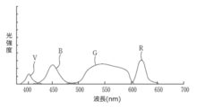
- FIG. 11 is a diagram showing an example of a spectrum of light generated by the light source device 5 shown in FIG.
- the light source device 5 shown in FIG. 2 includes a light source processor 51, a light source unit 52, and an optical path coupling unit 54.
- the light source unit 52 has, for example, a plurality of semiconductor light sources, each of which is turned on or off, and when the light source unit 52 is turned on, the amount of light emitted from each semiconductor light source is controlled to emit illumination light that illuminates the observation target.
- the light source unit 52 includes a V-LED (Violet Light Emitting Diode) 52a, a B-LED (Blue Light Emitting Diode) 52b, a G-LED (Green Light Emitting Diode) 52c, and an R-LED (Red Light).
- EmittingDiode It has a 52d 4-color LED.
- the V-LED 52a generates purple light V having a center wavelength of 405 ⁇ 10 nm and a wavelength range of 380 to 420 nm.
- the B-LED 52b generates blue light B having a center wavelength of 450 ⁇ 10 nm and a wavelength range of 420 to 500 nm.
- the G-LED 52c generates green light G having a wavelength range of 480 to 600 nm.
- the R-LED52d generates red light R having a center wavelength of 620 to 630 nm and a wavelength range of 600 to 650 nm.
- the light source processor 51 controls V-LED52a, B-LED52b, G-LED52c, and R-LED52d. By controlling each of the LEDs 52a to 52d independently, the light source processor 51 can emit violet light V, blue light B, green light G, or red light R by independently changing the amount of light. Further, the light source processor 51 emits white light having a light amount ratio of Vc: Bc: Gc: Rc among purple light V, blue light B, green light G, and red light R in the normal observation mode. , Each LED 52a to 52d is controlled. In addition, Vc, Bc, Gc, Rc> 0.
- the light source processor 51 has a light amount ratio of Vs: Bs: Gs: Rs with purple light V, blue light B, green light G, and red light R as short-wavelength narrow-band light.
- Each LED 52a to 52d is controlled so as to emit a special light.
- the light amount ratio Vs: Bs: Gs: Rs is different from the light amount ratio Vc: Bc: Gc: Rc used in the normal observation mode, and is appropriately determined according to the observation purpose. For example, when emphasizing superficial blood vessels, it is preferable to make Vs larger than other Bs, Gs, Rs, and when emphasizing mesopelagic blood vessels, Gs is made larger than other Vs, Gs, Rs. It is also preferable to increase the size.
- Control program The control program stored in the ROM of the control device 4 is stored in a computer-readable non-transitory storage medium.
- a "computer-readable storage medium” includes, for example, an optical medium such as a CD-ROM (Compact Disc-ROM), a magnetic storage medium such as a USB (Universal Serial Bus) memory, or a memory card. It is also possible to provide such a program by downloading via a network.
- the endoscope device 100 has been described as an example of the endoscope system of the present invention, the endoscope system of the present invention may be realized by a plurality of devices connected to each other via a network. For example, at least a part of the processing by the control device 4 may be executed by another device connected to the endoscope device 100 via a network.
- the display unit of the present invention may be realized by a plurality of display devices.
- the main area may be configured by one of the plurality of display devices, and the sub-area may be configured by the remaining display devices of the plurality of display devices.
- a discriminator that discriminates the stage of endoscopic examination A display unit that switches the display image according to the discrimination result by the discrimination unit is provided.
- the examination step includes a first step in which the endoscope is inserted into the subject and a second step in which the endoscope is withdrawn from the subject.
- the display unit displays a screen including information for assisting the insertion of the endoscope into the subject when it is determined that the stage of the examination is the first stage, and the examination is performed.
- An endoscope system that displays a screen containing information for supporting observation of an image obtained by the endoscope when it is determined that the step is the second step.
- the discrimination unit is an endoscope system that discriminates the stage of the inspection based on an image obtained by an image pickup device provided in the endoscope.
- the discriminating unit is an endoscope system that discriminates the stage of the inspection based on the detection result of the magnetic field generated from the magnetic field generating element provided in the endoscope.
- the discrimination unit is an endoscope system that discriminates the stage of the inspection based on the detection result of the magnetic field by the magnetic field detection element provided in the endoscope.
- the discrimination unit is an endoscope system that discriminates the stage of the inspection based on the acceleration information obtained from the accelerometer provided in the endoscope.
- the above endoscopes can switch and irradiate illumination lights having different emission spectra.
- the discriminating unit is an endoscope system that discriminates the stage of the inspection based on the switching of the illumination light emitted by the endoscope.
- the endoscopic system according to any one of (1) to (6).
- the display unit includes a live image obtained by an image pickup device provided in the endoscope when it is determined that the inspection stage is the first stage, information for supporting the insertion, and information for supporting the insertion.
- An endoscope system that displays a screen including the above-mentioned live image and information for supporting the above-mentioned observation when it is determined that the above-mentioned inspection stage is the above-mentioned second stage. ..
- the endoscopic system according to any one of (1) to (7).
- the information for supporting the insertion is an endoscope system including an image of the insertion shape of the endoscope.
- the endoscopic system according to any one of (1) to (8).
- the information to support the insertion is an endoscopic system that includes a map within the subject.
- the endoscopic system according to any one of (1) to (9).
- the information for supporting the insertion is an endoscope system including information indicating the elapsed time from the start of the insertion of the endoscope into the subject.
- the endoscopic system according to any one of (1) to (10).
- the information for supporting the observation is an endoscope system including a still image obtained by an image pickup device provided in the endoscope.
- the endoscopic system according to any one of (1) to (11).
- the information for supporting the observation is an endoscope system including information on a region of interest detected based on an image obtained from an image sensor provided in the endoscope.
- the endoscopic system according to any one of (1) to (12).
- the information for supporting the observation is an endoscope system including a similar case image selected based on an image obtained by an image sensor provided in the endoscope.
- the endoscopic system according to any one of (1) to (13).
- the information for supporting the observation is an endoscope system including information indicating a tumor that is likely to occur at the site in the subject during which the endoscope is being inserted.
- the endoscopic system according to any one of (1) to (14).
- the information for supporting the observation is an endoscope system including information indicating a recommended observation method of the site in the subject during which the endoscope is being inserted.
- the endoscopic system according to any one of (1) to (15).
- the information for supporting the observation is an endoscopy system including information showing past test results in the subject.
- the endoscopic system according to any one of (1) to (16).
- the information for supporting the insertion includes an image obtained by an image pickup device provided in the endoscope in a state where the subject is irradiated with white light.
- the information for supporting the observation is an endoscope system including an image obtained by the image pickup device in a state where the subject is irradiated with light having a different emission spectrum from the white light.
- the endoscopic system according to any one of (1) to (17).
- the information for supporting the observation is an endoscope system including information indicating the elapsed time from the start of withdrawal of the endoscope from the subject.
- the examination step includes a first step in which the endoscope is inserted into the subject and a second step in which the endoscope is withdrawn from the subject.
- a screen including information for supporting the insertion of the endoscope into the subject is displayed, and the stage of the examination is the first stage.
- a discriminator that discriminates the stage of endoscopic examination A display unit that switches the display image according to the discrimination result by the discrimination unit is provided.
- the examination stage is a first stage in which the endoscope is inserted into a first site in the subject, and a second step in the subject in which the endoscope is different from the first site.
- the display unit Based on the discrimination result by the discrimination unit, the display unit provides information for supporting the insertion of the endoscope into the portion of the subject in which the endoscope is being inserted, and the insertion.
- An endoscopic system that displays a screen that contains at least one of the information to assist in observing the area inside.
- the discrimination unit is an endoscope system that discriminates the stage of the inspection based on an image obtained by an image pickup device provided in the endoscope.
- the endoscopic system according to (21) or (22) is an endoscopic system that includes a map of the site being inserted.
- the endoscopic system according to any one of (21) to (23).
- the information to support the observation is an endoscopic system containing information indicating a tumor that is likely to occur at the site being inserted.
- the endoscopic system according to any one of (21) to (24).
- the information for supporting the observation is an endoscopic system including information indicating a recommended observation method for the site being inserted.
- the endoscopic system according to any one of (21) to (25).
- the first part and the second part are endoscopic systems that are the esophagus and stomach.
- the endoscopic system according to any one of (21) to (25).
- the first site and the second site are endoscopic systems that are two sites of a sigmoid colon, a descending colon, a transverse colon, and an ascending colon.
- the examination stage is a first stage in which the endoscope is inserted into a first site in the subject, and a second step in the subject in which the endoscope is different from the first site. Including the second stage Based on the determination result at the stage of the examination, the information for supporting the insertion of the endoscope into the part of the part in the subject into which the endoscope is being inserted, and the information of the part being inserted.
- a display method that displays a screen that contains information to assist observation and at least one of them.
- an endoscope system a control program, and a display method capable of providing useful information according to an examination stage to an endoscope operator.
Landscapes
- Health & Medical Sciences (AREA)
- Life Sciences & Earth Sciences (AREA)
- Surgery (AREA)
- Engineering & Computer Science (AREA)
- Physics & Mathematics (AREA)
- Optics & Photonics (AREA)
- Biomedical Technology (AREA)
- Medical Informatics (AREA)
- Pathology (AREA)
- Radiology & Medical Imaging (AREA)
- Biophysics (AREA)
- Veterinary Medicine (AREA)
- Heart & Thoracic Surgery (AREA)
- Nuclear Medicine, Radiotherapy & Molecular Imaging (AREA)
- Molecular Biology (AREA)
- Animal Behavior & Ethology (AREA)
- General Health & Medical Sciences (AREA)
- Public Health (AREA)
- Signal Processing (AREA)
- Microelectronics & Electronic Packaging (AREA)
- Endoscopes (AREA)
Abstract
Provided are an endoscope system, a control program, and a display method which are capable of providing useful information corresponding to the stage of examination to an operator of an endoscope. A system control unit 44 determines the stage of examination by an endoscope 1. A display device 7 switches display images in response to the result of stage determination by the system control unit 44. The stages of examination by the endoscope 1 include a first stage in which the endoscope 1 is inserted into a subject and a second stage in which the endoscope 1 is withdrawn from the subject. The display device 7 displays a screen which includes information to assist insertion of the endoscope 1 into the subject when it is determined that the examination is at the first stage and displays a screen which includes information to assist observation of an image obtained by the endoscope 1 when it is determined that the examination is at the second stage.
Description
本発明は、内視鏡システム、制御プログラム、及び表示方法に関する。
The present invention relates to an endoscopic system, a control program, and a display method.
従来、内視鏡の先端部に撮像素子を備え、撮像素子により得られるライブ画像を表示可能な内視鏡システムが知られている。また、特許文献1には、内視鏡の先端部が目標位置に到達したことをライブ画像に基づいて自動的に判断し、表示画面を切り替える工業用内視鏡システムが記載されている。
Conventionally, there is known an endoscope system in which an image sensor is provided at the tip of the endoscope and a live image obtained by the image sensor can be displayed. Further, Patent Document 1 describes an industrial endoscope system that automatically determines that the tip of an endoscope has reached a target position based on a live image and switches a display screen.
特許文献2には、挿入部先端が所定の位置に到達したか否かを撮像画像に基づいて判断し、表示出力の状態を切り替える挿入支援装置が記載されている。特許文献3には、外部医療機器の使用状態に応じたモードにより、モニタに表示される映像を変化させる医療用画像処理装置が記載されている。
Patent Document 2 describes an insertion support device that determines whether or not the tip of the insertion portion has reached a predetermined position based on an captured image and switches the display output state. Patent Document 3 describes a medical image processing device that changes an image displayed on a monitor according to a mode according to a usage state of an external medical device.
一般的に、内視鏡を用いた大腸内等の検査においては、内視鏡の挿入部を被検体内に挿入した後、内視鏡の挿入部を被検体内から引き抜きながら被検体内の観察が行われる。このような検査において、内視鏡の挿入部を被検体内に挿入する段階と、内視鏡の挿入部を被検体内から引き抜きながら観察を行う段階とでは、医師等の内視鏡の操作者にとって有用な情報が異なる。
Generally, in an examination of the inside of the large intestine using an endoscope, after inserting the insertion part of the endoscope into the subject, the insertion part of the endoscope is pulled out from the inside of the subject and inside the subject. Observations are made. In such an examination, the operation of the endoscope by a doctor or the like is performed between the stage of inserting the insertion part of the endoscope into the subject and the stage of observing while pulling out the insertion part of the endoscope from the inside of the subject. The information that is useful to the person is different.
例えば、内視鏡の挿入部を被検体内に挿入する段階においては、被検体に過度な負荷をかけないようにする必要があるため、内視鏡の操作の難易度が高く、内視鏡の挿入部の被検体内への円滑な挿入を支援する情報が有用である。
For example, at the stage of inserting the insertion part of the endoscope into the subject, it is necessary not to apply an excessive load to the subject, so that the operation of the endoscope is difficult and the endoscope is used. Information that supports the smooth insertion of the insertion part into the subject is useful.
一方で、内視鏡の挿入部を被検体内から引き抜きながら観察を行う段階においては、内視鏡の操作の難易度は挿入時ほど高くないが、ライブ画像等に基づく観察で特異箇所の見落とし等が無いように、観察を支援する情報が有用である。
On the other hand, at the stage of observing while pulling out the insertion part of the endoscope from the inside of the subject, the difficulty of operating the endoscope is not as high as at the time of insertion, but the singular part is overlooked by the observation based on the live image or the like. Information that supports observation is useful so that there is no such thing.
しかしながら、上記の従来技術では、検査の段階に応じた有用な情報を内視鏡の操作者に提供することができない。
However, the above-mentioned conventional technique cannot provide useful information according to the stage of examination to the operator of the endoscope.
本発明は、上記事情に鑑みてなされたものであり、検査の段階に応じた有用な情報を内視鏡の操作者に提供することのできる内視鏡システム、制御プログラム、及び表示方法を提供することを目的とする。
The present invention has been made in view of the above circumstances, and provides an endoscope system, a control program, and a display method capable of providing useful information according to an examination stage to an endoscope operator. The purpose is to do.
本発明の内視鏡システムは、内視鏡による検査の段階を判別する判別部と、上記判別部による判別結果に応じて表示画像を切り替える表示部と、を備え、上記検査の段階は、上記内視鏡が被検体内へ挿入される第1段階と、上記内視鏡が上記被検体内から引き抜かれる第2段階と、を含み、上記表示部は、上記検査の段階が上記第1段階であると判別された場合に、上記内視鏡の上記被検体内への挿入を支援するための情報を含む画面を表示し、上記検査の段階が上記第2段階であると判別された場合に、上記内視鏡により得られる画像の観察を支援するための情報を含む画面を表示するものである。
The endoscope system of the present invention includes a discriminating unit that discriminates the stage of inspection by the endoscope and a display unit that switches a display image according to the discriminating result by the discriminating unit. The display includes the first stage in which the endoscope is inserted into the subject and the second stage in which the endoscope is pulled out from the subject. In the display unit, the inspection stage is the first stage. When it is determined that the screen contains information for assisting the insertion of the endoscope into the subject, and the stage of the examination is determined to be the second stage. In addition, a screen including information for supporting the observation of the image obtained by the endoscope is displayed.
本発明の制御プログラムは、コンピュータを、上記の内視鏡システムの上記判別部及び上記表示部として機能させるためのものである。
The control program of the present invention is for causing the computer to function as the discriminating unit and the display unit of the endoscopic system.
本発明の表示方法は、内視鏡による検査の段階を判別し、上記検査の段階の判別結果に応じて表示画像を切り替える表示方法であって、上記検査の段階は、上記内視鏡が被検体内へ挿入される第1段階と、上記内視鏡が上記被検体内から引き抜かれる第2段階と、を含み、上記検査の段階が上記第1段階であると判別された場合に、上記内視鏡の上記被検体内への挿入を支援するための情報を含む画面を表示し、上記検査の段階が上記第2段階であると判別された場合に、上記内視鏡により得られる画像の観察を支援するための情報を含む画面を表示するものである。
The display method of the present invention is a display method in which the stage of inspection by an endoscope is discriminated and the display image is switched according to the determination result of the stage of the inspection, and the stage of the inspection is covered by the endoscope. When the stage of the examination is determined to be the first stage, the first stage of insertion into the sample and the second stage of the endoscope being pulled out of the subject are included. An image obtained by the endoscope when a screen containing information for assisting the insertion of the endoscope into the subject is displayed and the stage of the examination is determined to be the second stage. It displays a screen containing information to support the observation of.
本発明の別の内視鏡システムは、内視鏡による検査の段階を判別する判別部と、上記判別部による判別結果に応じて表示画像を切り替える表示部と、を備え、上記検査の段階は、上記内視鏡が被検体内の第1部位へ挿入される第1段階と、上記内視鏡が上記第1部位と異なる上記被検体内の第2部位へ挿入される第2段階と、を含み、上記表示部は、上記判別部による判別結果に基づいて、上記被検体内の部位のうち上記内視鏡を挿入中の部位への上記内視鏡の挿入を支援するための情報と、上記挿入中の部位の観察を支援するための情報と、の少なくともいずれかを含む画面を表示するものである。
Another endoscope system of the present invention includes a discriminating unit that discriminates the stage of inspection by the endoscope and a display unit that switches the display image according to the discriminating result by the discriminating unit. The first step in which the endoscope is inserted into the first site in the subject, and the second step in which the endoscope is inserted into the second site in the subject different from the first site. The display unit includes information for supporting the insertion of the endoscope into the portion of the subject in which the endoscope is being inserted, based on the discrimination result by the discrimination unit. , Information for assisting the observation of the site being inserted, and a screen containing at least one of the above.
本発明の別の制御プログラムは、コンピュータを、上記の内視鏡システムの上記判別部及び上記表示部として機能させるためのものである。
Another control program of the present invention is for causing the computer to function as the discriminating unit and the display unit of the endoscopic system.
本発明の別の制御方法は、内視鏡による検査の段階を判別し、上記検査の段階の判別結果に応じて表示画像を切り替える表示方法であって、上記検査の段階は、上記内視鏡が被検体内の第1部位へ挿入される第1段階と、上記内視鏡が上記第1部位と異なる上記被検体内の第2部位へ挿入される第2段階と、を含み、上記検査の段階の判別結果に基づいて、上記被検体内の部位のうち上記内視鏡を挿入中の部位への上記内視鏡の挿入を支援するための情報と、上記挿入中の部位の観察を支援するための情報と、の少なくともいずれかを含む画面を表示するものである。
Another control method of the present invention is a display method of discriminating the stage of examination by an endoscope and switching the display image according to the determination result of the stage of the examination, and the stage of the examination is the stage of the endoscope. The examination includes the first step in which the endoscope is inserted into the first site in the subject and the second step in which the endoscope is inserted into the second site in the subject different from the first site. Based on the discrimination result of the stage, information for supporting the insertion of the endoscope into the part of the part in the subject in which the endoscope is being inserted and observation of the part being inserted are provided. It displays a screen that contains at least one of the information to assist.
本発明によれば、検査の段階に応じた有用な情報を内視鏡の操作者に提供することのできる内視鏡システム、制御プログラム、及び表示方法を提供することができる。
According to the present invention, it is possible to provide an endoscope system, a control program, and a display method capable of providing useful information according to an examination stage to an endoscope operator.
以下、本発明の実施形態について図面を参照して説明する。
Hereinafter, embodiments of the present invention will be described with reference to the drawings.
(実施の形態1)
図1は、本発明の一実施形態である内視鏡装置100の一例を示す図である。 (Embodiment 1)
FIG. 1 is a diagram showing an example of anendoscope device 100 according to an embodiment of the present invention.
図1は、本発明の一実施形態である内視鏡装置100の一例を示す図である。 (Embodiment 1)
FIG. 1 is a diagram showing an example of an
内視鏡装置100は、本発明の内視鏡システムの一例である。図1に示すように、内視鏡装置100は、内視鏡1と、この内視鏡1が接続される制御装置4及び光源装置5と、を備える。
The endoscope device 100 is an example of the endoscope system of the present invention. As shown in FIG. 1, the endoscope device 100 includes an endoscope 1, a control device 4 to which the endoscope 1 is connected, and a light source device 5.
制御装置4には、内視鏡1によって被検体内を撮像して得られる撮像画像等を表示する表示装置7と、制御装置4に対して各種情報を入力するためのインタフェースである入力部6と、が接続されている。制御装置4は、内視鏡1、光源装置5、及び表示装置7を制御する。
The control device 4 includes a display device 7 that displays an image captured by imaging the inside of the subject with the endoscope 1, and an input unit 6 that is an interface for inputting various information to the control device 4. And are connected. The control device 4 controls the endoscope 1, the light source device 5, and the display device 7.
表示装置7は、表示画素が二次元状に配列された表示面を有し、この表示面の各表示画素に、画像データを構成する画素データが描画されることで、この画像データに基づく画像の表示が行われる。表示装置7は、制御装置4からの指令に応じて表示画像を切り替える表示部を構成する。
The display device 7 has a display surface in which display pixels are arranged in a two-dimensional manner, and pixel data constituting the image data is drawn on each display pixel of the display surface, so that an image based on the image data is drawn. Is displayed. The display device 7 constitutes a display unit that switches the display image in response to a command from the control device 4.
内視鏡1は、一方向に延びる管状部材であって被検体内に挿入される挿入部10と、挿入部10の基端部に設けられ、観察モード切替操作、撮像記録操作、鉗子操作、送気送水操作、及び吸引操作等を行うための操作部材が設けられた操作部11と、操作部11に隣接して設けられたアングルノブ12と、内視鏡1を光源装置5と制御装置4にそれぞれ着脱自在に接続するコネクタ部13A,13Bを含むユニバーサルコード13と、を含む。
The endoscope 1 is a tubular member extending in one direction and is provided at an insertion portion 10 inserted into a subject and a proximal end portion of the insertion portion 10, and is provided for an observation mode switching operation, an imaging recording operation, a forceps operation, and the like. An operation unit 11 provided with an operation member for performing an air supply / water supply operation, a suction operation, and the like, an angle knob 12 provided adjacent to the operation unit 11, and an endoscope 1 as a light source device 5 and a control device. Includes a universal cord 13 including connector portions 13A and 13B which are detachably connected to 4 respectively.
なお、図1では省略されているが、操作部11及び挿入部10の内部には、細胞又はポリープ等の生体組織を採取するための鉗子を挿入する鉗子孔、送気及び送水用のチャンネル、吸引用のチャンネル等の各種のチャンネルが設けられる。
Although omitted in FIG. 1, inside the operation unit 11 and the insertion unit 10, a forceps hole for inserting forceps for collecting biological tissues such as cells or polyps, a channel for air supply and water supply, and a channel for air supply and water supply, Various channels such as a suction channel are provided.
挿入部10は、可撓性を有する軟性部10Aと、軟性部10Aの先端に設けられた湾曲部10Bと、湾曲部10Bの先端に設けられた硬質の先端部10Cとから構成される。
The insertion portion 10 is composed of a flexible soft portion 10A, a curved portion 10B provided at the tip of the flexible portion 10A, and a hard tip portion 10C provided at the tip of the curved portion 10B.
湾曲部10Bは、アングルノブ12の回動操作により湾曲自在に構成されている。この湾曲部10Bは、内視鏡1が使用される被検体の部位等に応じて、任意の方向及び任意の角度に湾曲でき、先端部10Cを所望の方向に向けることができる。
The curved portion 10B is configured to be bendable by rotating the angle knob 12. The curved portion 10B can be curved in an arbitrary direction and an arbitrary angle according to the part of the subject in which the endoscope 1 is used, and the tip portion 10C can be directed in a desired direction.
図2は、図1に示す内視鏡装置100の内部構成を示す模式図である。
FIG. 2 is a schematic view showing the internal configuration of the endoscope device 100 shown in FIG.
光源装置5は、光源用プロセッサ51と、光源部52と、を備える。光源部52は、被写体に照射するための照明光を出射する。光源部52から出射された照明光は、ユニバーサルコード13に内蔵されたライトガイド53に入射し、挿入部10の先端部10Cに設けられた照明用レンズ50を通って被写体に照射される。
The light source device 5 includes a light source processor 51 and a light source unit 52. The light source unit 52 emits illumination light for irradiating the subject. The illumination light emitted from the light source unit 52 enters the light guide 53 built in the universal cord 13 and irradiates the subject through the illumination lens 50 provided at the tip portion 10C of the insertion portion 10.
光源部52としては、白色光を出射する白色光源、又は、白色光源とその他の色の光を出射する光源(例えば青色光を出射する青色光源)を含む複数の光源等が用いられる。先端部10Cの先端面には、光源部52から出射させる光の種類に合わせて照明用レンズ50が複数設けられていてもよい。
As the light source unit 52, a white light source that emits white light, or a plurality of light sources including a white light source and a light source that emits light of other colors (for example, a blue light source that emits blue light) are used. A plurality of illumination lenses 50 may be provided on the tip surface of the tip portion 10C according to the type of light emitted from the light source portion 52.
また、光源部52は、互いに発光スペクトルが異なる照明光を切り替えて照射可能であってもよい。互いに発光スペクトルが異なる照明光を切り替えて照射可能な光源部52の具体的な構成については図10,図11において説明する。
Further, the light source unit 52 may be capable of irradiating by switching illumination lights having different emission spectra from each other. A specific configuration of the light source unit 52 capable of switching and irradiating illumination lights having different emission spectra will be described with reference to FIGS. 10 and 11.
光源用プロセッサ51は、制御装置4のシステム制御部44と接続されている。光源用プロセッサ51は、システム制御部44からの指令に基づいて光源部52を制御する。
The light source processor 51 is connected to the system control unit 44 of the control device 4. The light source processor 51 controls the light source unit 52 based on a command from the system control unit 44.
内視鏡1の先端部10Cには、対物レンズ21及びレンズ群22を含む撮像光学系と、この撮像光学系を通して被写体を撮像する撮像素子23と、アナログデジタル変換回路(ADC)24と、RAM(Random Access Memory)等のメモリ25と、通信インタフェース(I/F)26と、撮像制御部27と、光源部52から出射された照明光を照明用レンズ50に導くためのライトガイド53と、が設けられている。
The tip portion 10C of the endoscope 1 includes an imaging optical system including an objective lens 21 and a lens group 22, an imaging element 23 that images a subject through the imaging optical system, an analog-digital conversion circuit (ADC) 24, and a RAM. A memory 25 such as (Random Access Memory), a communication interface (I / F) 26, an imaging control unit 27, a light guide 53 for guiding the illumination light emitted from the light source unit 52 to the illumination lens 50, and the like. Is provided.
ライトガイド53は、先端部10Cからユニバーサルコード13のコネクタ部13Aまで延びている。ユニバーサルコード13のコネクタ部13Aが光源装置5に接続された状態で、光源装置5の光源部52から出射される照明光がライトガイド53に入射可能な状態となる。
The light guide 53 extends from the tip portion 10C to the connector portion 13A of the universal cord 13. With the connector portion 13A of the universal cord 13 connected to the light source device 5, the illumination light emitted from the light source portion 52 of the light source device 5 can be incident on the light guide 53.
撮像素子23は、CCD(Charge Coupled Device)イメージセンサ又はCMOS(Complementary Metal Oxide Semiconductor)イメージセンサ等が用いられる。
As the image sensor 23, a CCD (Charge Coupled Device) image sensor, a CMOS (Complementary Metal Oxide Semiconductor) image sensor, or the like is used.
撮像素子23は、複数の画素が二次元状に配置された受光面を有し、上記の撮像光学系によってこの受光面に結像された光学像を各画素において電気信号(撮像信号)に変換し、ADC24に出力する。撮像素子23は、例えば原色又は補色等のカラーフィルタを搭載するものが用いられる。撮像素子23の受光面の各画素から出力される撮像信号の集合を撮像画像信号という。
The image sensor 23 has a light receiving surface in which a plurality of pixels are arranged two-dimensionally, and the optical image formed on the light receiving surface by the above imaging optical system is converted into an electric signal (imaging signal) in each pixel. Then, it is output to the ADC 24. As the image pickup device 23, for example, one equipped with a color filter such as a primary color or a complementary color is used. A set of image pickup signals output from each pixel on the light receiving surface of the image sensor 23 is called an image pickup image signal.
なお、光源部52として、白色光源から出射される白色光を複数色のカラーフィルタによって時分割で分光して照明光を生成するものを用いる場合には、撮像素子23はカラーフィルタを搭載していないものを用いてもよい。
When a light source unit 52 that generates illumination light by time-dividing white light emitted from a white light source with color filters of a plurality of colors is used, the image pickup element 23 is equipped with a color filter. You may use the one that does not exist.
撮像素子23は、対物レンズ21の光軸Axに対して受光面が垂直となる状態で先端部10Cに配置されていてもよいし、対物レンズ21の光軸Axに対して受光面が平行となる状態で先端部10Cに配置されていてもよい。
The image sensor 23 may be arranged at the tip portion 10C in a state where the light receiving surface is perpendicular to the optical axis Ax of the objective lens 21, or the light receiving surface is parallel to the optical axis Ax of the objective lens 21. It may be arranged in the tip portion 10C in such a state.
内視鏡1に設けられる撮像光学系は、撮像素子23と対物レンズ21との間における被写体からの光の光路上にあるレンズ、プリズム等の光学部材(上記のレンズ群22を含む)と、対物レンズ21と、によって構成される。撮像光学系は、対物レンズ21のみで構成される場合もある。
The image pickup optical system provided in the endoscope 1 includes optical members (including the above lens group 22) such as a lens and a prism on the optical path of light from the subject between the image pickup element 23 and the objective lens 21. It is composed of an objective lens 21 and. The imaging optical system may be composed of only the objective lens 21.
ADC24は、撮像素子23から出力された撮像信号を所定のビット数のデジタル信号に変換する。
The ADC 24 converts the image pickup signal output from the image pickup device 23 into a digital signal having a predetermined number of bits.
メモリ25は、ADC24でデジタル変換された撮像信号を一時的に記録する。
The memory 25 temporarily records the image pickup signal digitally converted by the ADC 24.
通信I/F26は、制御装置4の通信インタフェース(I/F)41と接続される。通信I/F26は、メモリ25に記録された撮像信号を、ユニバーサルコード13内の信号線を通して制御装置4に伝送する。
The communication I / F 26 is connected to the communication interface (I / F) 41 of the control device 4. The communication I / F 26 transmits the image pickup signal recorded in the memory 25 to the control device 4 through the signal line in the universal code 13.
撮像制御部27は、通信I/F26を介して制御装置4のシステム制御部44と接続されている。撮像制御部27は、通信I/F26で受信されるシステム制御部44からの指令に基づいて、撮像素子23、ADC24、及びメモリ25を制御する。
The image pickup control unit 27 is connected to the system control unit 44 of the control device 4 via the communication I / F 26. The image pickup control unit 27 controls the image pickup element 23, the ADC 24, and the memory 25 based on a command from the system control unit 44 received by the communication I / F 26.
制御装置4は、ユニバーサルコード13によって内視鏡1の通信I/F26と接続される通信I/F41と、信号処理部42と、表示コントローラ43と、システム制御部44と、記録媒体45と、を備える。
The control device 4 includes a communication I / F 41 connected to the communication I / F 26 of the endoscope 1 by a universal code 13, a signal processing unit 42, a display controller 43, a system control unit 44, a recording medium 45, and the like. To be equipped.
通信I/F41は、内視鏡1の通信I/F26から伝送されてきた撮像信号を受信して信号処理部42に伝達する。
The communication I / F 41 receives the image pickup signal transmitted from the communication I / F 26 of the endoscope 1 and transmits it to the signal processing unit 42.
信号処理部42は、通信I/F41から受けた撮像信号を一時記録するメモリを内蔵しており、メモリに記録された撮像信号の集合である撮像画像信号を処理(デモザイク処理又はガンマ補正処理等の画像処理)して、後述する認識処理が可能な形式の撮像画像データを生成する。信号処理部42によって生成された撮像画像データは、ハードディスク又はフラッシュメモリ等の記録媒体45に記録される。
The signal processing unit 42 has a built-in memory for temporarily recording the image pickup signal received from the communication I / F 41, and processes the image pickup image signal which is a set of the image pickup signals recorded in the memory (demosaic processing, gamma correction processing, etc.). Image processing) to generate captured image data in a format capable of recognition processing described later. The captured image data generated by the signal processing unit 42 is recorded on a recording medium 45 such as a hard disk or a flash memory.
表示コントローラ43は、信号処理部42によって生成された撮像画像データに基づく撮像画像を表示装置7に表示させる。信号処理部42によって生成された撮像画像データを構成する各画素データの座標は、表示装置7の表示面を構成するいずれかの表示画素の座標と対応付けて管理されている。
The display controller 43 causes the display device 7 to display an captured image based on the captured image data generated by the signal processing unit 42. The coordinates of each pixel data constituting the captured image data generated by the signal processing unit 42 are managed in association with the coordinates of any of the display pixels constituting the display surface of the display device 7.
システム制御部44は、制御装置4の各部を制御すると共に、内視鏡1の撮像制御部27と光源装置5の光源用プロセッサ51とに指令を送り、内視鏡装置100の全体を統括制御する。例えば、システム制御部44は、撮像制御部27を介して撮像素子23の制御を行う。また、システム制御部44は、光源用プロセッサ51を介して光源部52の制御を行う。
The system control unit 44 controls each part of the control device 4 and sends a command to the image pickup control unit 27 of the endoscope 1 and the light source processor 51 of the light source device 5, and controls the entire endoscope device 100 in an integrated manner. To do. For example, the system control unit 44 controls the image pickup device 23 via the image pickup control unit 27. Further, the system control unit 44 controls the light source unit 52 via the light source processor 51.
システム制御部44は、プログラムを実行して処理を行う各種のプロセッサと、RAMと、ROM(Read Only Memory)を含む。
The system control unit 44 includes various processors that execute programs and perform processing, RAM, and ROM (Read Only Memory).
各種のプロセッサとしては、プログラムを実行して各種処理を行う汎用的なプロセッサであるCPU(Central Processing Unit)、FPGA(Field Programmable Gate Array)等の製造後に回路構成を変更可能なプロセッサであるプログラマブルロジックデバイス(Programmable Logic Device:PLD)、又はASIC(Application Specific Integrated Circuit)等の特定の処理を実行させるために専用に設計された回路構成を有するプロセッサである専用電気回路等が含まれる。
As various processors, programmable logic which is a processor whose circuit configuration can be changed after manufacturing such as CPU (Central Processing Unit), FPGA (Field Programmable Gate Array), which is a general-purpose processor that executes a program and performs various processes. A dedicated electric circuit or the like, which is a processor having a circuit configuration specially designed for executing a specific process such as a device (Programmable Logic Device: PLD) or an ASIC (Application Special Integrated Circuit), is included.
これら各種のプロセッサの構造は、より具体的には、半導体素子等の回路素子を組み合わせた電気回路である。
More specifically, the structure of these various processors is an electric circuit that combines circuit elements such as semiconductor elements.
システム制御部44は、各種のプロセッサのうちの1つで構成されてもよいし、同種又は異種の2つ以上のプロセッサの組み合わせ(例えば、複数のFPGAの組み合わせ又はCPUとFPGAの組み合わせ)で構成されてもよい。
The system control unit 44 may be composed of one of various processors, or may be composed of a combination of two or more processors of the same type or different types (for example, a combination of a plurality of FPGAs or a combination of a CPU and an FPGA). May be done.
図3は、図2に示した制御装置4のシステム制御部44の機能ブロックの一例を示す図である。
FIG. 3 is a diagram showing an example of a functional block of the system control unit 44 of the control device 4 shown in FIG.
システム制御部44のプロセッサは、システム制御部44に内蔵されるROMに格納された検査支援プログラムを実行することにより、撮像画像データ取得部44A、段階判別部44B、及び表示制御部44Cを備える表示制御装置として機能する。
The processor of the system control unit 44 executes an inspection support program stored in the ROM built in the system control unit 44 to include a display image data acquisition unit 44A, a stage determination unit 44B, and a display control unit 44C. Functions as a control device.
撮像画像データ取得部44Aは、撮像素子23によって被検体内を撮像して得られた撮像信号を信号処理部42によって処理して得られた撮像画像データを順次取得する。
The image pickup image data acquisition unit 44A sequentially acquires the image pickup image data obtained by processing the image pickup signal obtained by imaging the inside of the subject by the image pickup element 23 by the signal processing unit 42.
段階判別部44Bは、各種の情報に基づいて、内視鏡1を用いた検査の段階を判別する。段階判別部44Bによる各種の情報に基づく検査の段階の判別は、各種の情報に基づく特定のアルゴリズムによる判別であってもよいし、各種の情報と検索段階の情報との組み合わせによる機械学習を行った学習モデルによる判別であってもよい。
The stage determination unit 44B determines the stage of the examination using the endoscope 1 based on various information. The stage discrimination unit 44B may discriminate the inspection stage based on various information by a specific algorithm based on various information, or perform machine learning by combining various information with the information of the search stage. It may be discriminated by a learning model.
内視鏡1を用いた検査の段階には、例えば、内視鏡1の挿入部10が被検体内へ挿入される挿入段階と、内視鏡1の挿入部10が被検体内から引き抜かれる引き抜き段階と、が含まれる。挿入段階は、本発明の第1段階の一例である。引き抜き段階は、本発明の第2段階の一例である。また、内視鏡1を用いた検査の段階には、これらの他に、内視鏡1の挿入部10が被検体内へ挿入される前の段階や、内視鏡1の挿入部10が被検体内から引き抜かれた後の段階が含まれてもよい。
In the stage of examination using the endoscope 1, for example, an insertion stage in which the insertion portion 10 of the endoscope 1 is inserted into the subject and an insertion stage in which the insertion portion 10 of the endoscope 1 is pulled out from the subject. The withdrawal stage and is included. The insertion step is an example of the first step of the present invention. The pull-out step is an example of the second step of the present invention. In addition to these, the stage of the examination using the endoscope 1 includes the stage before the insertion portion 10 of the endoscope 1 is inserted into the subject and the insertion portion 10 of the endoscope 1. The stage after being withdrawn from the subject may be included.
例えば、段階判別部44Bは、撮像画像データ取得部44Aにより得られる撮像画像データに基づいて検査の段階を判別する。具体的には、一般的に、内視鏡を用いた大腸内等の検査においては、内視鏡1の挿入部10を盲腸まで挿入した後に、内視鏡1の挿入部10の引き抜きが開始される。このため、撮像画像データに基づいて盲腸が検出されるまでは挿入段階、撮像画像データに基づいて盲腸が検出された後は引き抜き段階であると判別することができる。
For example, the stage determination unit 44B determines the inspection stage based on the captured image data obtained by the captured image data acquisition unit 44A. Specifically, in general, in an examination of the inside of the large intestine using an endoscope, the insertion portion 10 of the endoscope 1 is pulled out after the insertion portion 10 of the endoscope 1 is inserted into the cecum. Will be done. Therefore, it can be determined that the insertion stage is performed until the cecum is detected based on the captured image data, and the extraction stage is performed after the cecum is detected based on the captured image data.
表示制御部44Cは、表示コントローラ43に指令を出して、表示装置7に表示させる画面の制御を行う。具体的には、表示制御部44Cは、段階判別部44Bによる検査の段階の判別結果に応じた情報を含む画面を表示装置7に表示させる。
The display control unit 44C issues a command to the display controller 43 to control the screen to be displayed on the display device 7. Specifically, the display control unit 44C causes the display device 7 to display a screen including information according to the determination result of the inspection stage by the stage determination unit 44B.
図4は、実施の形態1において内視鏡1の挿入段階で表示装置7に表示される画面の一例を示す図である。
FIG. 4 is a diagram showing an example of a screen displayed on the display device 7 at the insertion stage of the endoscope 1 in the first embodiment.
段階判別部44Bによって検査の段階が内視鏡装置100の挿入段階であると判別されると、表示制御部44Cは、例えば図4に示す画面60を表示装置7に表示させる。画面60には、ライブ画像61と、大腸マップ62と、挿入形状画像63と、が含まれる。
When the stage determination unit 44B determines that the inspection stage is the insertion stage of the endoscope device 100, the display control unit 44C causes the display device 7 to display, for example, the screen 60 shown in FIG. The screen 60 includes a live image 61, a large intestine map 62, and an inserted shape image 63.
画面60の左側はメイン領域となっており、ライブ画像61はこのメイン領域に配置されている。画面60の右側はサブ領域となっており、大腸マップ62及び挿入形状画像63はこのサブ領域に配置されている。
The left side of the screen 60 is the main area, and the live image 61 is arranged in this main area. The right side of the screen 60 is a sub-region, and the large intestine map 62 and the insertion shape image 63 are arranged in this sub-region.
ライブ画像61は、撮像素子23から連続して出力される撮像信号により得られる画像をリアルタイムで示す動画像である。
The live image 61 is a moving image showing an image obtained by an imaging signal continuously output from the image sensor 23 in real time.
大腸マップ62及び挿入形状画像63は、内視鏡1の挿入部10の被検体内への挿入を支援するための挿入支援情報を構成する。大腸マップ62は、内視鏡1の挿入対象の被検体内のマップの一例であり、内視鏡1の挿入対象の被検体の大腸を示す画像である。大腸マップ62は、例えば被検体内を撮像して得られたものであってもよいし、予め用意された一般的な大腸の画像であってもよい。
The large intestine map 62 and the insertion shape image 63 constitute insertion support information for supporting the insertion of the insertion portion 10 of the endoscope 1 into the subject. The large intestine map 62 is an example of a map in the subject to be inserted by the endoscope 1, and is an image showing the large intestine of the subject to be inserted by the endoscope 1. The large intestine map 62 may be, for example, an image obtained by imaging the inside of a subject, or may be a general image of the large intestine prepared in advance.
挿入形状画像63は、被検体内へ挿入された内視鏡1の挿入部10の挿入形状を示す画像である。例えば、挿入形状画像63は、内視鏡1の先端部10Cに備えられた磁界発生素子から発生した磁界の検出結果に基づいて生成された画像である。この場合に、例えば、内視鏡装置100は、被検体外から、被検体内に挿入された内視鏡1の磁界発生素子からの磁界を検出する磁界検出装置をさらに備え、システム制御部44はその磁界検出装置による検出結果に基づいて挿入形状画像63を生成する。
The insertion shape image 63 is an image showing the insertion shape of the insertion portion 10 of the endoscope 1 inserted into the subject. For example, the insertion shape image 63 is an image generated based on the detection result of the magnetic field generated from the magnetic field generating element provided in the tip portion 10C of the endoscope 1. In this case, for example, the endoscope device 100 further includes a magnetic field detection device that detects a magnetic field from the magnetic field generating element of the endoscope 1 inserted into the subject from outside the subject, and the system control unit 44 Generates the insertion shape image 63 based on the detection result by the magnetic field detection device.
また、挿入形状画像63は、内視鏡1の先端部10Cに備えられた磁界検出素子による磁界の検出結果に基づいて生成された画像であってもよい。この場合に、例えば、内視鏡装置100は、被検体外から被検体内へ向けて磁界を発生させる磁界発生素子をさらに備え、システム制御部44は、内視鏡1に備えられた磁界検出素子による磁界の検出結果に基づいて挿入形状画像63を生成する。
Further, the insertion shape image 63 may be an image generated based on the detection result of the magnetic field by the magnetic field detection element provided in the tip portion 10C of the endoscope 1. In this case, for example, the endoscope device 100 further includes a magnetic field generating element that generates a magnetic field from outside the subject to the inside of the subject, and the system control unit 44 further includes a magnetic field detection unit provided in the endoscope 1. The insertion shape image 63 is generated based on the detection result of the magnetic field by the element.
内視鏡1の操作者は、大腸マップ62及び挿入形状画像63を見ることで、内視鏡1の挿入部10の被検体内への挿入を容易に行うことができる。
The operator of the endoscope 1 can easily insert the insertion portion 10 of the endoscope 1 into the subject by looking at the large intestine map 62 and the insertion shape image 63.
図5は、実施の形態1において内視鏡1の引き抜き段階で表示装置7に表示される画面の一例を示す図である。
FIG. 5 is a diagram showing an example of a screen displayed on the display device 7 at the stage of pulling out the endoscope 1 in the first embodiment.
段階判別部44Bによって検査の段階が内視鏡装置100の引き抜き段階であると判別されると、表示制御部44Cは、例えば図5に示す画面70を表示装置7に表示させる。画面70には、ライブ画像61と、サムネイル情報71と、大腸撮像マップ72と、が含まれる。
When the stage determination unit 44B determines that the inspection stage is the extraction stage of the endoscope device 100, the display control unit 44C causes the display device 7 to display, for example, the screen 70 shown in FIG. The screen 70 includes a live image 61, thumbnail information 71, and a large intestine imaging map 72.
ライブ画像61は図4の例と同様にメイン領域に配置されている。サムネイル情報71及び大腸撮像マップ72は、図4に示した大腸マップ62及び挿入形状画像63に代えてサブ領域(左側の領域)に配置されている。
The live image 61 is arranged in the main area as in the example of FIG. The thumbnail information 71 and the large intestine imaging map 72 are arranged in a sub region (the region on the left side) in place of the large intestine map 62 and the inserted shape image 63 shown in FIG.
サムネイル情報71及び大腸撮像マップ72は、内視鏡1により得られる撮像画像の観察を支援するための観察支援情報を構成する。観察支援情報は、例えば内視鏡1により得られる撮像画像に基づく診断を支援するための情報であってもよい。
The thumbnail information 71 and the large intestine imaging map 72 constitute observation support information for supporting the observation of the captured image obtained by the endoscope 1. The observation support information may be, for example, information for supporting a diagnosis based on an captured image obtained by the endoscope 1.
サムネイル情報71は、内視鏡1の被検体への挿入中、又は内視鏡1の被検体からの引き抜き中に得られた複数の静止画像を縮小して示す情報である。図5に示す例では、サムネイル情報71には4枚の静止画像が含まれており、各静止画像には通し番号「01」、「02」、「03」、「04」が付されている。
The thumbnail information 71 is information showing a plurality of still images obtained by reducing the plurality of still images obtained during the insertion of the endoscope 1 into the subject or the extraction of the endoscope 1 from the subject. In the example shown in FIG. 5, the thumbnail information 71 includes four still images, and each still image is given serial numbers "01", "02", "03", and "04".
また、サムネイル情報71には、図5に示す例のように、各静止画像に関する他のテキスト情報(図5の「~~~~」の部分)が含まれてもよい。このテキスト情報は、例えば、対応する静止画像が得られた位置や時間、対応する静止画像が得られた際に操作者が入力した所見、又は対応する静止画像が得られた際の画像解析の結果等である。
Further, the thumbnail information 71 may include other text information (the part “~~~~” in FIG. 5) relating to each still image as in the example shown in FIG. This text information is, for example, the position and time when the corresponding still image was obtained, the findings input by the operator when the corresponding still image was obtained, or the image analysis when the corresponding still image was obtained. The result etc.
大腸撮像マップ72は、図4に示した大腸マップ62において、上記の各静止画像が得られた箇所を、上記の通し番号によって示すものである。
The large intestine imaging map 72 shows the locations where the above still images were obtained in the large intestine map 62 shown in FIG. 4 by the above serial numbers.
サムネイル情報71及び大腸撮像マップ72を見ることで、内視鏡1の操作者は、内視鏡1により得られる撮像画像の観察や、内視鏡1により得られる撮像画像に基づく診断を容易に行うことができる。
By looking at the thumbnail information 71 and the large intestine imaging map 72, the operator of the endoscope 1 can easily observe the captured image obtained by the endoscope 1 and make a diagnosis based on the captured image obtained by the endoscope 1. It can be carried out.
また、図4,図5に示したように、システム制御部44は、挿入段階においてライブ画像61と挿入支援情報とを含む画面を表示装置7に表示させ、引き抜き段階においてライブ画像61と、観察支援情報とを含む画面を表示装置7に表示させてもよい。これにより、主にライブ画像61を観察しながら行う検査において、ライブ画像61を表示しつつ、挿入段階及び挿入段階のそれぞれにおいて有用な各支援情報を表示することができる。
Further, as shown in FIGS. 4 and 5, the system control unit 44 causes the display device 7 to display a screen including the live image 61 and the insertion support information in the insertion stage, and observes the live image 61 in the extraction stage. A screen including the support information may be displayed on the display device 7. Thereby, in the inspection mainly performed while observing the live image 61, it is possible to display each support information useful in each of the insertion stage and the insertion stage while displaying the live image 61.
図6は、実施の形態1における制御装置4による表示制御処理の一例を示すフローチャートである。内視鏡1を用いた検査時に、制御装置4は、例えば図6に示す処理を実行する。
FIG. 6 is a flowchart showing an example of the display control process by the control device 4 in the first embodiment. At the time of inspection using the endoscope 1, the control device 4 executes, for example, the process shown in FIG.
まず、制御装置4は、内視鏡1を用いた検査の段階を判別する(ステップS61)。次に、制御装置4は、ステップS61の結果に基づいて、内視鏡1を用いた検査の段階が、内視鏡1が被検体内へ挿入される挿入段階であるか否かを判断する(ステップS62)。挿入段階でない場合(ステップS62:No)は、制御装置4はステップS61へ戻る。
First, the control device 4 determines the stage of the inspection using the endoscope 1 (step S61). Next, the control device 4 determines, based on the result of step S61, whether or not the stage of the examination using the endoscope 1 is the insertion stage in which the endoscope 1 is inserted into the subject. (Step S62). If it is not the insertion stage (step S62: No), the control device 4 returns to step S61.
ステップS62において、挿入段階である場合(ステップS62:Yes)は、制御装置4は、表示装置7のメイン領域(左側の領域)へのライブ画像61の表示を開始する(ステップS63)。また、制御装置4は、サブ領域(右側の領域)への挿入支援情報(大腸マップ62及び挿入形状画像63)の表示を開始する(ステップS64)。
In step S62, when the insertion stage is in progress (step S62: Yes), the control device 4 starts displaying the live image 61 in the main area (left area) of the display device 7 (step S63). Further, the control device 4 starts displaying the insertion support information (large intestine map 62 and insertion shape image 63) in the sub region (region on the right side) (step S64).
次に、制御装置4は、内視鏡1を用いた検査の段階を判別する(ステップS65)。次に、制御装置4は、ステップS65の結果に基づいて、内視鏡1を用いた検査の段階が、内視鏡1が被検体内から引き抜かれる引き抜き段階であるか否かを判断する(ステップS66)。引き抜き段階でない場合(ステップS66:No)は、制御装置4はステップS65へ戻る。
Next, the control device 4 determines the stage of the inspection using the endoscope 1 (step S65). Next, the control device 4 determines, based on the result of step S65, whether or not the step of the examination using the endoscope 1 is the pulling step in which the endoscope 1 is pulled out from the subject (the pulling step). Step S66). If it is not the pull-out stage (step S66: No), the control device 4 returns to step S65.
ステップS66において、引き抜き段階である場合(ステップS66:Yes)は、制御装置4は、サブ領域への観察支援情報(サムネイル情報71及び大腸撮像マップ72)の表示を開始し(ステップS67)、一連の処理を終了する。
In step S66, in the case of the extraction step (step S66: Yes), the control device 4 starts displaying the observation support information (thumbnail information 71 and the large intestine imaging map 72) in the sub-region (step S67), and a series of steps. Ends the processing of.
このように、実施の形態1の内視鏡装置100は、内視鏡1による検査の段階を判別し、挿入段階である場合に、内視鏡1の被検体内への挿入を支援するための挿入支援情報を含む画面を表示し、引き抜き段階である場合に、内視鏡1により得られる画像の観察を支援するための観察支援情報を含む画面を表示する。これにより、検査の段階に応じた有用な情報を内視鏡の操作者に提供することができる。
As described above, the endoscope device 100 of the first embodiment determines the stage of the examination by the endoscope 1 and supports the insertion of the endoscope 1 into the subject when it is the insertion stage. A screen including the insertion support information of the above is displayed, and a screen including the observation support information for supporting the observation of the image obtained by the endoscope 1 is displayed in the extraction stage. As a result, useful information according to the stage of examination can be provided to the operator of the endoscope.
<検査の段階の判別方法の変形例>
段階判別部44Bが撮像画像データに基づいて検査の段階を判別する構成について説明したが、このような構成に限らない。 <Modified example of the method for determining the inspection stage>
Although the configuration in which thestage determination unit 44B determines the inspection stage based on the captured image data has been described, the configuration is not limited to such a configuration.
段階判別部44Bが撮像画像データに基づいて検査の段階を判別する構成について説明したが、このような構成に限らない。 <Modified example of the method for determining the inspection stage>
Although the configuration in which the
例えば、段階判別部44Bは、内視鏡1の先端部10Cに備えられた磁界発生素子から発生した磁界の検出結果に基づいて検査の段階を判別してもよい。この場合に、例えば、内視鏡装置100は、被検体外から、被検体内に挿入された内視鏡1の磁界発生素子からの磁界を検出する磁界検出装置をさらに備え、段階判別部44Bはその磁界検出装置による検出結果に基づいて検査の段階を判別する。
For example, the stage discriminating unit 44B may discriminate the inspection stage based on the detection result of the magnetic field generated from the magnetic field generating element provided in the tip portion 10C of the endoscope 1. In this case, for example, the endoscope device 100 further includes a magnetic field detection device that detects a magnetic field from the magnetic field generating element of the endoscope 1 inserted into the subject from outside the subject, and the stage determination unit 44B Determines the inspection stage based on the detection result by the magnetic field detector.
また、段階判別部44Bは、内視鏡1の先端部10Cに備えられた磁界検出素子による磁界の検出結果に基づいて検査の段階を判別してもよい。この場合に、例えば、内視鏡装置100は、被検体外から被検体内へ向けて磁界を発生させる磁界発生素子をさらに備え、段階判別部44Bは、内視鏡1に備えられた磁界検出素子による磁界の検出結果に基づいて検査の段階を判別する。
Further, the stage discriminating unit 44B may discriminate the inspection stage based on the detection result of the magnetic field by the magnetic field detecting element provided in the tip portion 10C of the endoscope 1. In this case, for example, the endoscope device 100 further includes a magnetic field generating element that generates a magnetic field from outside the subject to the inside of the subject, and the stage determination unit 44B includes a magnetic field detection unit provided in the endoscope 1. The inspection stage is determined based on the detection result of the magnetic field by the element.
また、段階判別部44Bは、内視鏡1の先端部10Cに備えられた加速度計から得られる加速度情報に基づいて検査の段階を判別してもよい。例えば、挿入段階において内視鏡1は内視鏡1の先端の方向へ移動しており、引き抜き段階において内視鏡1は内視鏡1の先端の方向とは反対側に移動している。このため、上記の加速度情報に基づいて内視鏡1の移動方向を特定することにより、検査の段階が挿入段階及び引き抜き段階のいずれであるかを判別することができる。
Further, the stage discriminating unit 44B may discriminate the stage of inspection based on the acceleration information obtained from the accelerometer provided at the tip portion 10C of the endoscope 1. For example, in the insertion stage, the endoscope 1 is moving toward the tip of the endoscope 1, and in the pulling stage, the endoscope 1 is moving in the direction opposite to the direction of the tip of the endoscope 1. Therefore, by specifying the moving direction of the endoscope 1 based on the above acceleration information, it is possible to determine whether the inspection stage is the insertion stage or the extraction stage.
また、内視鏡1が、互いに発光スペクトルが異なる照明光を切り替えて照射可能である場合に、段階判別部44Bは、内視鏡1が照射する照明光の切り替わりに基づいて検査の段階を判別してもよい。例えば、図2に示した光源装置5において、白色光と、画像強調用の特殊光と、を切り替え可能であるとする。
Further, when the endoscope 1 can switch and irradiate illumination lights having different emission spectra, the stage determination unit 44B determines the inspection stage based on the change of the illumination light emitted by the endoscope 1. You may. For example, in the light source device 5 shown in FIG. 2, it is assumed that white light and special light for image enhancement can be switched.
この切り替えは、内視鏡1の操作者による光源切り替え操作によるものであってもよいし、上記の撮像画像データ取得部44Aにより得られる撮像画像データ等に基づいて自動的に行われるものであってもよい。一般的に、挿入段階においては白色光が用いられ、引き抜き段階においては特殊光が用いられるため、内視鏡1が照射する照明光の切り替わりに基づいて、検査の段階を判別することが可能である。
This switching may be performed by a light source switching operation by the operator of the endoscope 1, or is automatically performed based on the captured image data or the like obtained by the above-mentioned captured image data acquisition unit 44A. You may. Generally, white light is used in the insertion stage and special light is used in the extraction stage. Therefore, it is possible to determine the inspection stage based on the switching of the illumination light emitted by the endoscope 1. is there.
<挿入支援情報の変形例>
システム制御部44が、内視鏡1の被検体内への挿入を支援するための情報として、被検体内のマップ(大腸マップ62)及び内視鏡1の挿入形状の画像(挿入形状画像63)を表示させる構成について説明したが、このような構成に限らない。 <Modification example of insertion support information>
As information for supporting the insertion of theendoscope 1 into the subject by the system control unit 44, a map in the subject (large intestine map 62) and an image of the insertion shape of the endoscope 1 (insertion shape image 63). ) Has been described, but it is not limited to such a configuration.
システム制御部44が、内視鏡1の被検体内への挿入を支援するための情報として、被検体内のマップ(大腸マップ62)及び内視鏡1の挿入形状の画像(挿入形状画像63)を表示させる構成について説明したが、このような構成に限らない。 <Modification example of insertion support information>
As information for supporting the insertion of the
例えば、システム制御部44は、内視鏡1の被検体内への挿入を支援するための情報として、被検体内のマップ(大腸マップ62)及び内視鏡1の挿入形状の画像(挿入形状画像63)のいずれかを表示装置7に表示させてもよい。
For example, the system control unit 44 provides information for supporting the insertion of the endoscope 1 into the subject, such as a map in the subject (large intestine map 62) and an image of the insertion shape of the endoscope 1 (insertion shape). Any one of the images 63) may be displayed on the display device 7.
又は、システム制御部44は、内視鏡1の被検体内への挿入を支援するための情報として、内視鏡1の被検体内への挿入が開始されてからの経過時間等を表示装置7に表示させてもよい。これにより、内視鏡1の操作者は、内視鏡1の挿入に伴う被検体への負荷を容易に把握しながら挿入操作を行うことができる。
Alternatively, the system control unit 44 displays the elapsed time from the start of insertion of the endoscope 1 into the subject as information for supporting the insertion of the endoscope 1 into the subject. It may be displayed in 7. As a result, the operator of the endoscope 1 can perform the insertion operation while easily grasping the load on the subject due to the insertion of the endoscope 1.
<観察支援情報の変形例>
システム制御部44が、観察を支援するための情報として、内視鏡1に備えられた撮像素子23により得られた静止画像(サムネイル情報71)及び静止画像が得られた被検体内の位置を示す情報(大腸撮像マップ72)を表示させる構成について説明したが、このような構成に限らない。 <Modification example of observation support information>
As information for supporting observation, thesystem control unit 44 determines the still image (thumbnail information 71) obtained by the image sensor 23 provided in the endoscope 1 and the position in the subject in which the still image is obtained. Although the configuration for displaying the indicated information (large intestine imaging map 72) has been described, the configuration is not limited to such a configuration.
システム制御部44が、観察を支援するための情報として、内視鏡1に備えられた撮像素子23により得られた静止画像(サムネイル情報71)及び静止画像が得られた被検体内の位置を示す情報(大腸撮像マップ72)を表示させる構成について説明したが、このような構成に限らない。 <Modification example of observation support information>
As information for supporting observation, the
例えば、システム制御部44が、観察を支援するための情報として、内視鏡1に備えられた撮像素子23により得られた静止画像(サムネイル情報71)のみを表示装置7に表示させる構成であってもよい。また、サムネイル情報71は、上記のテキスト情報や通し番号を含まないものであってもよい。
For example, the system control unit 44 has a configuration in which only the still image (thumbnail information 71) obtained by the image pickup element 23 provided in the endoscope 1 is displayed on the display device 7 as information for supporting the observation. You may. Further, the thumbnail information 71 may not include the above-mentioned text information and serial number.
また、システム制御部44が、観察を支援するための情報として、内視鏡1に備えられた撮像素子23より得られる画像に基づいて検出された各種の情報を表示装置7に表示させる構成であってもよい。
Further, the system control unit 44 is configured to display various information detected based on the image obtained from the image pickup device 23 provided in the endoscope 1 on the display device 7 as information for supporting the observation. There may be.
撮像素子23より得られる画像に基づいて検出される情報は、例えば注目領域に関する情報である。注目領域に関する情報は、例えば腫瘍等の病変などの画像や、病変の輪郭線などである。又は、注目領域に関する情報は、検出された病変などの数や大きさ等の情報であってもよい。
The information detected based on the image obtained from the image sensor 23 is, for example, information about the region of interest. Information about the region of interest is, for example, an image of a lesion such as a tumor, an outline of the lesion, or the like. Alternatively, the information regarding the region of interest may be information such as the number and size of detected lesions.
また、撮像素子23より得られる画像に基づいて検出される情報は、撮像素子23より得られる画像に基づいて選択された類似症例画像であってもよい。例えば、過去の様々な症例における撮像画像が、内視鏡装置100の内部又は外部のデータベースに登録されておいる。システム制御部44は、撮像素子23より得られる画像に類似する画像を上記のデータベースから検索し、検索により得られた画像を類似症例画像として表示装置7に表示させる。
Further, the information detected based on the image obtained from the image sensor 23 may be a similar case image selected based on the image obtained from the image sensor 23. For example, captured images of various past cases are registered in an internal or external database of the endoscope device 100. The system control unit 44 searches the above database for an image similar to the image obtained from the image sensor 23, and displays the image obtained by the search on the display device 7 as a similar case image.
また、システム制御部44が、観察を支援するための情報として、内視鏡1を挿入中の被検体内の部位において発生しやすい腫瘍を示す情報を表示装置7に表示させる構成であってもよい。例えば、大腸の各部位について、発生しやすい腫瘍の名称等が内視鏡装置100の内部又は外部のデータベースに登録されている。システム制御部44は、内視鏡1を挿入中の大腸内の部位を特定し、特定した部位について発生しやすい腫瘍の名称等を上記のデータベースから検索し、検索により得られた腫瘍の名称等を表示装置7に表示させる。内視鏡1を挿入中の大腸内の部位の特定は、例えば、撮像素子23より得られる画像や、上記の磁界発生素子及び磁界検出装置の各組み合わせを用いて行うことができる。
Further, even if the system control unit 44 is configured to display on the display device 7 information indicating a tumor that is likely to occur at a site in the subject into which the endoscope 1 is being inserted, as information for supporting observation. Good. For example, for each part of the large intestine, the names of tumors that are likely to occur are registered in the internal or external database of the endoscope device 100. The system control unit 44 identifies the site in the large intestine during which the endoscope 1 is being inserted, searches the above database for the names of tumors that are likely to occur in the identified sites, and the names of the tumors obtained by the search. Is displayed on the display device 7. The portion in the large intestine during which the endoscope 1 is inserted can be specified by using, for example, an image obtained from the image pickup device 23 or a combination of the above magnetic field generating element and the magnetic field detecting device.
また、システム制御部44が、観察を支援するための情報として、内視鏡1を挿入中の被検体内の部位の推奨観察方法を示す情報を表示装置7に表示させる構成であってもよい。例えば、大腸の各部位について、推奨されるライブ画像の観察方法が内視鏡装置100の内部又は外部のデータベースに登録されている。システム制御部44は、内視鏡1を挿入中の大腸内の部位を特定し、特定した部位について推奨される観察方法を上記のデータベースから検索し、検索により得られた観察方法を表示装置7に表示させる。内視鏡1を挿入中の大腸内の部位の特定は、例えば、撮像素子23より得られる画像や、上記の磁界発生素子及び磁界検出装置の各組み合わせを用いて行うことができる。
Further, the system control unit 44 may have a configuration in which the display device 7 displays information indicating a recommended observation method of a portion in the subject in which the endoscope 1 is being inserted as information for supporting observation. .. For example, for each part of the large intestine, a recommended method for observing a live image is registered in an internal or external database of the endoscope device 100. The system control unit 44 identifies a part in the large intestine during which the endoscope 1 is being inserted, searches the above database for a recommended observation method for the specified part, and displays the observation method obtained by the search on the display device 7. To display. The portion in the large intestine during which the endoscope 1 is inserted can be specified by using, for example, an image obtained from the image pickup device 23 or a combination of the above magnetic field generating element and the magnetic field detecting device.
また、システム制御部44が、観察を支援するための情報として、被検体内の過去の検査結果を示す情報を表示装置7に表示させる構成であってもよい。例えば、システム制御部44は、内視鏡1を挿入中の被検体について過去に行われた検査の結果を示す情報を、内視鏡装置100の内部又は外部のデータベースから取得し、取得した検査の結果を示す情報を表示装置7に表示させる。検査の結果を示す情報は、例えば、その検査における撮像により得られた画像や、その画像に基づく解析の結果などである。
Further, the system control unit 44 may be configured to display the information indicating the past test results in the subject on the display device 7 as the information for supporting the observation. For example, the system control unit 44 acquires information indicating the results of examinations performed in the past on the subject into which the endoscope 1 is inserted from an internal or external database of the endoscope device 100, and the acquired examinations. Information indicating the result of the above is displayed on the display device 7. The information indicating the result of the inspection is, for example, an image obtained by imaging in the inspection, a result of analysis based on the image, and the like.
また、システム制御部44が、観察を支援するための情報として、内視鏡1の被検体内からの引き抜きが開始されてからの経過時間を示す情報を表示装置7に表示させてもよい。これにより、内視鏡1の操作者は、内視鏡1の引き抜きに伴う被検体への負荷を容易に把握しながら引き抜き操作を行うことができる。
Further, the system control unit 44 may display the information indicating the elapsed time from the start of withdrawal of the endoscope 1 from the subject on the display device 7 as the information for supporting the observation. As a result, the operator of the endoscope 1 can perform the extraction operation while easily grasping the load on the subject due to the extraction of the endoscope 1.
<挿入支援情報及び観察支援情報の変形例>
又は、システム制御部44が、挿入段階において、挿入を支援するための情報として、被検体内に白色光を照射した状態で撮像素子23により得られた画像を含む画面を表示装置7に表示させ、引き抜き段階において、観察を支援するための情報として、被検体内に白色光と発光スペクトルが異なる特殊光を照射した状態で撮像素子23により得られた画像を含む画面を表示装置7に表示させてもよい。特殊光を照射した状態で撮像素子23により得られる画像は、上記の観察や診断に適した画像である。 <Variation example of insertion support information and observation support information>
Alternatively, in the insertion stage, thesystem control unit 44 causes the display device 7 to display a screen including an image obtained by the image sensor 23 in a state where the subject is irradiated with white light as information for supporting the insertion. In the extraction stage, as information for supporting observation, the display device 7 displays a screen including an image obtained by the image sensor 23 in a state where the subject is irradiated with special light having a different emission spectrum from white light. You may. The image obtained by the image pickup device 23 in a state of being irradiated with special light is an image suitable for the above observation and diagnosis.
又は、システム制御部44が、挿入段階において、挿入を支援するための情報として、被検体内に白色光を照射した状態で撮像素子23により得られた画像を含む画面を表示装置7に表示させ、引き抜き段階において、観察を支援するための情報として、被検体内に白色光と発光スペクトルが異なる特殊光を照射した状態で撮像素子23により得られた画像を含む画面を表示装置7に表示させてもよい。特殊光を照射した状態で撮像素子23により得られる画像は、上記の観察や診断に適した画像である。 <Variation example of insertion support information and observation support information>
Alternatively, in the insertion stage, the
例えば、システム制御部44は、挿入段階において、光源装置5を制御して白色光を照射しつつ、撮像素子23により得られた撮像信号に基づくライブ画像61を含む画面を表示装置7に表示させる。また、システム制御部44は、引き抜き段階において、光源装置5を制御して特殊光を照射しつつ、撮像素子23により得られた撮像信号に基づくライブ画像61を含む画面を表示装置7に表示させる。互いに発光スペクトルが異なる照明光を切り替えて照射可能な光源装置5の構成については図10,図11において説明する。
For example, in the insertion stage, the system control unit 44 controls the light source device 5 to irradiate white light, and causes the display device 7 to display a screen including a live image 61 based on the image pickup signal obtained by the image pickup device 23. .. Further, in the extraction stage, the system control unit 44 controls the light source device 5 to irradiate special light, and causes the display device 7 to display a screen including a live image 61 based on the image pickup signal obtained by the image pickup element 23. .. The configuration of the light source device 5 capable of switching and irradiating illumination lights having different emission spectra will be described with reference to FIGS. 10 and 11.
(実施の形態2)
実施の形態2について、実施の形態1と異なる部分について説明する。実施の形態1においては挿入段階及び引き抜き段階を判別し、これらの各段階において有用な情報を表示する構成について説明した。実施の形態2においては、内視鏡1の挿入部10が被検体内のいずれの部位に挿入されている段階かを判別し、これらの各段階において有用な情報を表示する構成について説明する。 (Embodiment 2)
A part different from the first embodiment will be described with respect to the second embodiment. In the first embodiment, a configuration in which an insertion stage and a pull-out stage are discriminated and useful information is displayed in each of these stages has been described. In the second embodiment, a configuration will be described in which it is determined at which site in the subject theinsertion portion 10 of the endoscope 1 is inserted, and useful information is displayed in each of these stages.
実施の形態2について、実施の形態1と異なる部分について説明する。実施の形態1においては挿入段階及び引き抜き段階を判別し、これらの各段階において有用な情報を表示する構成について説明した。実施の形態2においては、内視鏡1の挿入部10が被検体内のいずれの部位に挿入されている段階かを判別し、これらの各段階において有用な情報を表示する構成について説明する。 (Embodiment 2)
A part different from the first embodiment will be described with respect to the second embodiment. In the first embodiment, a configuration in which an insertion stage and a pull-out stage are discriminated and useful information is displayed in each of these stages has been described. In the second embodiment, a configuration will be described in which it is determined at which site in the subject the
ここでは、内視鏡1の挿入部10を、被検体の口から、食道を経由して胃に挿入して行われる検査について説明する。この場合に、段階判別部44Bによって判別される検査の段階には、例えば、内視鏡1の挿入部10が食道へ挿入される食道挿入段階と、内視鏡1の挿入部10が胃へ挿入される胃挿入段階と、が含まれる。食道は、被検体内の第1部位の一例である。胃は、被検体内の第2部位の一例である。
Here, an examination performed by inserting the insertion portion 10 of the endoscope 1 into the stomach from the mouth of the subject via the esophagus will be described. In this case, the examination stage determined by the stage discriminating unit 44B includes, for example, an esophageal insertion stage in which the insertion portion 10 of the endoscope 1 is inserted into the esophagus and an insertion portion 10 of the endoscope 1 into the stomach. Includes the gastric insertion stage, which is inserted. The esophagus is an example of a first site in a subject. The stomach is an example of a second site in a subject.
例えば、段階判別部44Bは、撮像画像データ取得部44Aにより得られる撮像画像データに基づいて食道挿入段階及び胃挿入段階を判別する。
For example, the stage discrimination unit 44B discriminates between the esophageal insertion stage and the gastric insertion stage based on the captured image data obtained by the captured image data acquisition unit 44A.
図7は、実施の形態2において内視鏡1の食道挿入段階で表示装置7に表示される画面の一例を示す図である。
FIG. 7 is a diagram showing an example of a screen displayed on the display device 7 at the esophageal insertion stage of the endoscope 1 in the second embodiment.
段階判別部44Bによって検査の段階が内視鏡装置100の食道挿入段階であると判別されると、表示制御部44Cは、例えば図7に示す画面80を表示装置7に表示させる。画面80には、ライブ画像61と、食道マップ101と、挿入形状画像63と、が含まれる。
When the stage determination unit 44B determines that the inspection stage is the esophageal insertion stage of the endoscope device 100, the display control unit 44C displays, for example, the screen 80 shown in FIG. 7 on the display device 7. The screen 80 includes a live image 61, an esophageal map 101, and an inserted shape image 63.
ライブ画像61はメイン領域(左側の領域)に配置されている。食道マップ101及び挿入形状画像63はサブ領域(右側の領域)に配置されている。
The live image 61 is arranged in the main area (the area on the left side). The esophageal map 101 and the inserted shape image 63 are arranged in a sub region (the region on the right side).
ライブ画像61は、撮像素子23から連続して出力される撮像信号により得られる画像をリアルタイムで示す動画像である。
The live image 61 is a moving image showing an image obtained by an imaging signal continuously output from the image sensor 23 in real time.
食道マップ101及び挿入形状画像63は、内視鏡1の挿入部10の食道への挿入を支援するための食道挿入支援情報を構成する。
The esophageal map 101 and the insertion shape image 63 constitute esophageal insertion support information for supporting the insertion of the insertion portion 10 of the endoscope 1 into the esophagus.
食道マップ101は、内視鏡1の挿入対象の被検体の食道を示す画像である。食道マップ101は、例えば被検体内を撮像して得られたものであってもよいし、予め用意された一般的な大腸の画像であってもよい。図7に示す例では、挿入形状画像63は、被検体内の食道へ挿入されている内視鏡1の挿入部10の形状を示している。
The esophageal map 101 is an image showing the esophagus of the subject to be inserted into the endoscope 1. The esophageal map 101 may be, for example, an image obtained by imaging the inside of a subject, or may be a general image of the large intestine prepared in advance. In the example shown in FIG. 7, the insertion shape image 63 shows the shape of the insertion portion 10 of the endoscope 1 inserted into the esophagus in the subject.
食道マップ101及び挿入形状画像63を見ることで、内視鏡1の操作者は、内視鏡1の挿入部10の食道への挿入を容易に行うことができる。
By looking at the esophageal map 101 and the insertion shape image 63, the operator of the endoscope 1 can easily insert the insertion portion 10 of the endoscope 1 into the esophagus.
図8は、実施の形態2において内視鏡1の胃挿入段階で表示装置7に表示される画面の一例を示す図である。
FIG. 8 is a diagram showing an example of a screen displayed on the display device 7 at the gastric insertion stage of the endoscope 1 in the second embodiment.
段階判別部44Bによって検査の段階が内視鏡装置100の胃挿入段階であると判別されると、表示制御部44Cは、例えば図8に示す画面90を表示装置7に表示させる。画面90には、ライブ画像61と、胃マップ102と、挿入形状画像63と、が含まれる。
When the stage determination unit 44B determines that the examination stage is the gastric insertion stage of the endoscope device 100, the display control unit 44C causes the display device 7 to display, for example, the screen 90 shown in FIG. The screen 90 includes a live image 61, a stomach map 102, and an inserted shape image 63.
ライブ画像61は図7の例と同様にメイン領域に配置されている。胃マップ102及び挿入形状画像63は、図7に示した食道マップ101及び挿入形状画像63に代えてサブ領域に配置されている。
The live image 61 is arranged in the main area as in the example of FIG. The stomach map 102 and the inserted shape image 63 are arranged in a sub-region instead of the esophageal map 101 and the inserted shape image 63 shown in FIG. 7.
胃マップ102及び挿入形状画像63は、内視鏡1の挿入部10の被検体内の胃への挿入を支援するための胃挿入支援情報を構成する。
The stomach map 102 and the insertion shape image 63 constitute gastric insertion support information for supporting the insertion of the insertion portion 10 of the endoscope 1 into the stomach in the subject.
胃マップ102は、内視鏡1の挿入対象の被検体の胃を示す画像である。胃マップ102は、例えば被検体内を撮像して得られたものであってもよいし、予め用意された一般的な大腸の画像であってもよい。図8に示す例では、挿入形状画像63は、被検体内の胃へ挿入されている内視鏡1の挿入部10の形状を示している。
The stomach map 102 is an image showing the stomach of the subject to be inserted into the endoscope 1. The stomach map 102 may be, for example, an image obtained by imaging the inside of a subject, or may be a general image of the large intestine prepared in advance. In the example shown in FIG. 8, the insertion shape image 63 shows the shape of the insertion portion 10 of the endoscope 1 inserted into the stomach in the subject.
胃マップ102及び挿入形状画像63を見ることで、内視鏡1の操作者は、内視鏡1の挿入部10の胃への挿入を容易に行うことができる。
By looking at the stomach map 102 and the insertion shape image 63, the operator of the endoscope 1 can easily insert the insertion portion 10 of the endoscope 1 into the stomach.
図9は、実施の形態2における制御装置4による表示制御処理の一例を示すフローチャートである。内視鏡1を用いた検査時に、制御装置4は、例えば図9に示す処理を実行する。
FIG. 9 is a flowchart showing an example of the display control process by the control device 4 in the second embodiment. At the time of inspection using the endoscope 1, the control device 4 executes, for example, the process shown in FIG.
まず、制御装置4は、内視鏡1を用いた検査の段階を判別する(ステップS91)。次に、制御装置4は、ステップS91の結果に基づいて、内視鏡1を用いた検査の段階が、内視鏡1が被検体内の食道へ挿入される食道挿入段階であるか否かを判断する(ステップS92)。食道挿入段階でない場合(ステップS92:No)は、制御装置4はステップS91へ戻る。
First, the control device 4 determines the stage of the inspection using the endoscope 1 (step S91). Next, based on the result of step S91, the control device 4 determines whether or not the stage of the examination using the endoscope 1 is the esophageal insertion stage in which the endoscope 1 is inserted into the esophagus in the subject. Is determined (step S92). If it is not in the esophageal insertion stage (step S92: No), the control device 4 returns to step S91.
ステップS92において、食道挿入段階である場合(ステップS92:Yes)は、制御装置4は、表示装置7のメイン領域(左側の領域)へのライブ画像61の表示を開始する(ステップS93)。また、制御装置4は、サブ領域(右側の領域)への食道挿入支援情報(食道マップ101及び挿入形状画像63)の表示を開始する(ステップS94)。
In step S92, when the esophagus insertion stage is in progress (step S92: Yes), the control device 4 starts displaying the live image 61 in the main area (left area) of the display device 7 (step S93). Further, the control device 4 starts displaying the esophagus insertion support information (esophageal map 101 and insertion shape image 63) in the sub region (the region on the right side) (step S94).
次に、制御装置4は、内視鏡1を用いた検査の段階を判別する(ステップS95)。次に、制御装置4は、ステップS95の結果に基づいて、内視鏡1を用いた検査の段階が、内視鏡1が被検体内の胃へ挿入される胃挿入段階であるか否かを判断する(ステップS96)。胃挿入段階でない場合(ステップS96:No)は、制御装置4はステップS95へ戻る。
Next, the control device 4 determines the stage of the inspection using the endoscope 1 (step S95). Next, based on the result of step S95, the control device 4 determines whether or not the stage of the examination using the endoscope 1 is the gastric insertion stage in which the endoscope 1 is inserted into the stomach in the subject. Is determined (step S96). If it is not the gastric insertion stage (step S96: No), the control device 4 returns to step S95.
ステップS96において、胃挿入段階である場合(ステップS96:Yes)は、制御装置4は、サブ領域への胃挿入支援情報(胃マップ102及び挿入形状画像63)の表示を開始し(ステップS97)、一連の処理を終了する。
In step S96, when the gastric insertion stage (step S96: Yes), the control device 4 starts displaying gastric insertion support information (stomach map 102 and insertion shape image 63) in the sub-region (step S97). , Ends a series of processing.
このように、実施の形態2の内視鏡装置100は、内視鏡1による検査の段階を判別し、食道挿入段階である場合に、内視鏡1の食道への挿入を支援するための食道挿入支援情報を含む画面を表示し、胃挿入段階である場合に、内視鏡1の胃への挿入を支援するための胃挿入支援情報を含む画面を表示する。これにより、検査の段階に応じた有用な情報を内視鏡の操作者に提供することができる。
As described above, the endoscope device 100 of the second embodiment determines the stage of the examination by the endoscope 1 and supports the insertion of the endoscope 1 into the esophagus when it is the esophageal insertion stage. A screen including esophageal insertion support information is displayed, and a screen including gastric insertion support information for supporting insertion of the endoscope 1 into the stomach is displayed when the gastric insertion stage is in progress. As a result, useful information according to the stage of examination can be provided to the operator of the endoscope.
<第1部位及び第2部位の変形例>
第1部位及び第2部位の一例として食道及び胃について説明したが、第1部位及び第2部位はこれらに限らない。例えば、内視鏡1を用いて大腸の検査を行う場合、第1部位及び第2部位は、S状結腸、下行結腸、横行結腸及び上行結腸のうちの2つの部位であってもよい。また、挿入が判別される部位は3つ以上であってもよく、システム制御部44は、挿入が判別された各部位を対象に、対象の部位の挿入部10の挿入を支援する情報を表示装置7に表示させてもよい。 <Modification example of the first part and the second part>
Although the esophagus and stomach have been described as examples of the first and second sites, the first and second sites are not limited thereto. For example, when examining the large intestine using theendoscope 1, the first and second sites may be two sites, a sigmoid colon, a descending colon, a transverse colon, and an ascending colon. Further, the number of sites where insertion is determined may be three or more, and the system control unit 44 displays information for supporting the insertion of the insertion section 10 of the target site for each site where insertion is determined. It may be displayed on the device 7.
第1部位及び第2部位の一例として食道及び胃について説明したが、第1部位及び第2部位はこれらに限らない。例えば、内視鏡1を用いて大腸の検査を行う場合、第1部位及び第2部位は、S状結腸、下行結腸、横行結腸及び上行結腸のうちの2つの部位であってもよい。また、挿入が判別される部位は3つ以上であってもよく、システム制御部44は、挿入が判別された各部位を対象に、対象の部位の挿入部10の挿入を支援する情報を表示装置7に表示させてもよい。 <Modification example of the first part and the second part>
Although the esophagus and stomach have been described as examples of the first and second sites, the first and second sites are not limited thereto. For example, when examining the large intestine using the
<検査の段階の判別方法の変形例>
段階判別部44Bが撮像画像データに基づいて検査の段階(挿入部位)を判別する構成について説明したが、このような構成に限らない。 <Modified example of the method for determining the inspection stage>
Although the configuration in which thestage discriminating unit 44B discriminates the inspection stage (insertion site) based on the captured image data has been described, the configuration is not limited to such a configuration.
段階判別部44Bが撮像画像データに基づいて検査の段階(挿入部位)を判別する構成について説明したが、このような構成に限らない。 <Modified example of the method for determining the inspection stage>
Although the configuration in which the
例えば、段階判別部44Bは、内視鏡1の先端部10Cに備えられた磁界発生素子から発生した磁界の検出結果に基づいて検査の段階を判別してもよい。この場合に、例えば、内視鏡装置100は、被検体外から、被検体内に挿入された内視鏡1の磁界発生素子からの磁界を検出する磁界検出装置をさらに備え、段階判別部44Bはその磁界検出装置による検出結果に基づいて検査の段階を判別する。
For example, the stage discriminating unit 44B may discriminate the inspection stage based on the detection result of the magnetic field generated from the magnetic field generating element provided in the tip portion 10C of the endoscope 1. In this case, for example, the endoscope device 100 further includes a magnetic field detection device that detects a magnetic field from the magnetic field generating element of the endoscope 1 inserted into the subject from outside the subject, and the stage determination unit 44B Determines the inspection stage based on the detection result by the magnetic field detector.
また、段階判別部44Bは、内視鏡1の先端部10Cに備えられた磁界検出素子による磁界の検出結果に基づいて検査の段階を判別してもよい。この場合に、例えば、内視鏡装置100は、被検体外から被検体内へ向けて磁界を発生させる磁界発生素子をさらに備え、段階判別部44Bは、内視鏡1に備えられた磁界検出素子による磁界の検出結果に基づいて検査の段階を判別する。
Further, the stage discriminating unit 44B may discriminate the inspection stage based on the detection result of the magnetic field by the magnetic field detecting element provided in the tip portion 10C of the endoscope 1. In this case, for example, the endoscope device 100 further includes a magnetic field generating element that generates a magnetic field from outside the subject to the inside of the subject, and the stage determination unit 44B includes a magnetic field detection unit provided in the endoscope 1. The inspection stage is determined based on the detection result of the magnetic field by the element.
(実施の形態1,2の組み合わせ)
実施の形態1,2を組み合わせてもよい。すなわち、システム制御部44は、例えば、被検体内の複数の部位毎の挿入段階と、引き抜き段階と、を判別し、判別した段階に応じて、挿入中の部位毎の挿入支援情報、あるいは観察支援情報を表示装置7に表示させてもよい。 (Combination ofEmbodiments 1 and 2)
Embodiments 1 and 2 may be combined. That is, thesystem control unit 44 discriminates, for example, an insertion stage and a pull-out stage for each of a plurality of parts in the subject, and insert support information or observation for each part being inserted according to the discriminated stage. The support information may be displayed on the display device 7.
実施の形態1,2を組み合わせてもよい。すなわち、システム制御部44は、例えば、被検体内の複数の部位毎の挿入段階と、引き抜き段階と、を判別し、判別した段階に応じて、挿入中の部位毎の挿入支援情報、あるいは観察支援情報を表示装置7に表示させてもよい。 (Combination of
Embodiments 1 and 2 may be combined. That is, the
(光源装置5について)
図10は、互いに発光スペクトルが異なる照明光を切り替えて照射可能な光源装置5の一例を示す図である。図11は、図10に示した光源装置5が発生させる光のスペクトルの一例を示す図である。 (About the light source device 5)
FIG. 10 is a diagram showing an example of alight source device 5 capable of switching and irradiating illumination lights having different emission spectra. FIG. 11 is a diagram showing an example of a spectrum of light generated by the light source device 5 shown in FIG.
図10は、互いに発光スペクトルが異なる照明光を切り替えて照射可能な光源装置5の一例を示す図である。図11は、図10に示した光源装置5が発生させる光のスペクトルの一例を示す図である。 (About the light source device 5)
FIG. 10 is a diagram showing an example of a
図10に示すように、図2に示した光源装置5は、光源用プロセッサ51と、光源部52と、光路結合部54と、を備える。
As shown in FIG. 10, the light source device 5 shown in FIG. 2 includes a light source processor 51, a light source unit 52, and an optical path coupling unit 54.
光源部52は、例えば、複数の半導体光源を有し、これらをそれぞれ点灯又は消灯し、点灯する場合には各半導体光源の発光量を制御することにより、観察対象を照明する照明光を発する。本実施形態では、光源部52は、V-LED(Violet Light Emitting Diode)52a、B-LED(Blue Light Emitting Diode)52b、G-LED(Green Light Emitting Diode)52c、及びR-LED(Red Light Emitting Diode)52dの4色のLEDを有する。
The light source unit 52 has, for example, a plurality of semiconductor light sources, each of which is turned on or off, and when the light source unit 52 is turned on, the amount of light emitted from each semiconductor light source is controlled to emit illumination light that illuminates the observation target. In the present embodiment, the light source unit 52 includes a V-LED (Violet Light Emitting Diode) 52a, a B-LED (Blue Light Emitting Diode) 52b, a G-LED (Green Light Emitting Diode) 52c, and an R-LED (Red Light). EmittingDiode) It has a 52d 4-color LED.
図11に示すように、V-LED52aは、中心波長405±10nm、波長範囲380~420nmの紫色光Vを発生する。B-LED52bは、中心波長450±10nm、波長範囲420~500nmの青色光Bを発生する。G-LED52cは、波長範囲が480~600nmに及ぶ緑色光Gを発生する。R-LED52dは、中心波長620~630nmで、波長範囲が600~650nmに及ぶ赤色光Rを発生する。
As shown in FIG. 11, the V-LED 52a generates purple light V having a center wavelength of 405 ± 10 nm and a wavelength range of 380 to 420 nm. The B-LED 52b generates blue light B having a center wavelength of 450 ± 10 nm and a wavelength range of 420 to 500 nm. The G-LED 52c generates green light G having a wavelength range of 480 to 600 nm. The R-LED52d generates red light R having a center wavelength of 620 to 630 nm and a wavelength range of 600 to 650 nm.
光源用プロセッサ51は、V-LED52a、B-LED52b、G-LED52c、及びR-LED52dを制御する。光源用プロセッサ51は、各LED52a~52dをそれぞれ独立に制御することで、紫色光V、青色光B、緑色光G、又は赤色光Rをそれぞれ独立に光量を変えて発光可能である。また、光源用プロセッサ51は、通常観察モード時には、紫色光V、青色光B、緑色光G、及び赤色光R間の光量比がVc:Bc:Gc:Rcとなる白色光を発光するように、各LED52a~52dを制御する。なお、Vc、Bc、Gc、Rc>0である。
The light source processor 51 controls V-LED52a, B-LED52b, G-LED52c, and R-LED52d. By controlling each of the LEDs 52a to 52d independently, the light source processor 51 can emit violet light V, blue light B, green light G, or red light R by independently changing the amount of light. Further, the light source processor 51 emits white light having a light amount ratio of Vc: Bc: Gc: Rc among purple light V, blue light B, green light G, and red light R in the normal observation mode. , Each LED 52a to 52d is controlled. In addition, Vc, Bc, Gc, Rc> 0.
また、光源用プロセッサ51は、特殊観察モード時には、短波長の狭帯域光としての紫色光V、青色光B、緑色光G、及び赤色光Rとの光量比がVs:Bs:Gs:Rsとなる特殊光を発光するように、各LED52a~52dを制御する。光量比Vs:Bs:Gs:Rsは、通常観察モード時に使用する光量比Vc:Bc:Gc:Rcと異なっており、観察目的に応じて適宜定められる。例えば、表層血管を強調する場合には、Vsを、他のBs、Gs、Rsよりも大きくすることが好ましく、中深層血管を強調する場合には、Gsを、他のVs、Gs、Rsよりも大きくすることが好ましい。
Further, in the special observation mode, the light source processor 51 has a light amount ratio of Vs: Bs: Gs: Rs with purple light V, blue light B, green light G, and red light R as short-wavelength narrow-band light. Each LED 52a to 52d is controlled so as to emit a special light. The light amount ratio Vs: Bs: Gs: Rs is different from the light amount ratio Vc: Bc: Gc: Rc used in the normal observation mode, and is appropriately determined according to the observation purpose. For example, when emphasizing superficial blood vessels, it is preferable to make Vs larger than other Bs, Gs, Rs, and when emphasizing mesopelagic blood vessels, Gs is made larger than other Vs, Gs, Rs. It is also preferable to increase the size.
図10,図11に示した光源装置5の構成によれば、制御装置4からの指令により、互いに発光スペクトルが異なる照明光を切り替えて照射することが可能である。
According to the configuration of the light source device 5 shown in FIGS. 10 and 11, it is possible to switch and irradiate illumination lights having different emission spectra by a command from the control device 4.
(制御プログラム)
制御装置4のROMに記憶される制御プログラムは、プログラムをコンピュータが読取可能な一時的でない(non-transitory)記憶媒体に記憶される。このような「コンピュータ読取可能な記憶媒体」は、例えば、CD-ROM(Compact Disc-ROM)等の光学媒体や、USB(Universal Serial Bus)メモリ又はメモリカード等の磁気記憶媒体等を含む。また、このようなプログラムを、ネットワークを介したダウンロードによって提供することもできる。 (Control program)
The control program stored in the ROM of thecontrol device 4 is stored in a computer-readable non-transitory storage medium. Such a "computer-readable storage medium" includes, for example, an optical medium such as a CD-ROM (Compact Disc-ROM), a magnetic storage medium such as a USB (Universal Serial Bus) memory, or a memory card. It is also possible to provide such a program by downloading via a network.
制御装置4のROMに記憶される制御プログラムは、プログラムをコンピュータが読取可能な一時的でない(non-transitory)記憶媒体に記憶される。このような「コンピュータ読取可能な記憶媒体」は、例えば、CD-ROM(Compact Disc-ROM)等の光学媒体や、USB(Universal Serial Bus)メモリ又はメモリカード等の磁気記憶媒体等を含む。また、このようなプログラムを、ネットワークを介したダウンロードによって提供することもできる。 (Control program)
The control program stored in the ROM of the
(内視鏡システムの別の形態)
本発明の内視鏡システムの一例として内視鏡装置100を説明したが、本発明の内視鏡システムは、ネットワークを介して互いに接続される複数の装置によって実現されてもよい。例えば、上記の制御装置4による処理の少なくとも一部を、内視鏡装置100とネットワークを介して接続される他の装置により実行する構成としてもよい。 (Another form of endoscopic system)
Although theendoscope device 100 has been described as an example of the endoscope system of the present invention, the endoscope system of the present invention may be realized by a plurality of devices connected to each other via a network. For example, at least a part of the processing by the control device 4 may be executed by another device connected to the endoscope device 100 via a network.
本発明の内視鏡システムの一例として内視鏡装置100を説明したが、本発明の内視鏡システムは、ネットワークを介して互いに接続される複数の装置によって実現されてもよい。例えば、上記の制御装置4による処理の少なくとも一部を、内視鏡装置100とネットワークを介して接続される他の装置により実行する構成としてもよい。 (Another form of endoscopic system)
Although the
(表示部の別の形態)
本発明の表示部の一例として表示装置7を説明したが、本発明の表示部は、複数の表示装置によって実現されてもよい。この場合に、複数の表示装置のうち1つの表示装置により上記のメイン領域を構成し、複数の表示装置のうち残りの表示装置により上記のサブ領域を構成してもよい。 (Another form of display)
Although thedisplay device 7 has been described as an example of the display unit of the present invention, the display unit of the present invention may be realized by a plurality of display devices. In this case, the main area may be configured by one of the plurality of display devices, and the sub-area may be configured by the remaining display devices of the plurality of display devices.
本発明の表示部の一例として表示装置7を説明したが、本発明の表示部は、複数の表示装置によって実現されてもよい。この場合に、複数の表示装置のうち1つの表示装置により上記のメイン領域を構成し、複数の表示装置のうち残りの表示装置により上記のサブ領域を構成してもよい。 (Another form of display)
Although the
以上説明してきたように、本明細書には以下の事項が開示されている。
As explained above, the following matters are disclosed in this specification.
(1)
内視鏡による検査の段階を判別する判別部と、
上記判別部による判別結果に応じて表示画像を切り替える表示部と、を備え、
上記検査の段階は、上記内視鏡が被検体内へ挿入される第1段階と、上記内視鏡が上記被検体内から引き抜かれる第2段階と、を含み、
上記表示部は、上記検査の段階が上記第1段階であると判別された場合に、上記内視鏡の上記被検体内への挿入を支援するための情報を含む画面を表示し、上記検査の段階が上記第2段階であると判別された場合に、上記内視鏡により得られる画像の観察を支援するための情報を含む画面を表示する内視鏡システム。 (1)
A discriminator that discriminates the stage of endoscopic examination,
A display unit that switches the display image according to the discrimination result by the discrimination unit is provided.
The examination step includes a first step in which the endoscope is inserted into the subject and a second step in which the endoscope is withdrawn from the subject.
The display unit displays a screen including information for assisting the insertion of the endoscope into the subject when it is determined that the stage of the examination is the first stage, and the examination is performed. An endoscope system that displays a screen containing information for supporting observation of an image obtained by the endoscope when it is determined that the step is the second step.
(2)
(1)記載の内視鏡システムであって、
上記判別部は、上記内視鏡に備えられた撮像素子により得られる画像に基づいて上記検査の段階を判別する内視鏡システム。 (2)
(1) The endoscopic system described.
The discrimination unit is an endoscope system that discriminates the stage of the inspection based on an image obtained by an image pickup device provided in the endoscope.
(1)記載の内視鏡システムであって、
上記判別部は、上記内視鏡に備えられた撮像素子により得られる画像に基づいて上記検査の段階を判別する内視鏡システム。 (2)
(1) The endoscopic system described.
The discrimination unit is an endoscope system that discriminates the stage of the inspection based on an image obtained by an image pickup device provided in the endoscope.
(3)
(1)記載の内視鏡システムであって、
上記判別部は、上記内視鏡に備えられた磁界発生素子から発生した磁界の検出結果に基づいて上記検査の段階を判別する内視鏡システム。 (3)
(1) The endoscopic system described.
The discriminating unit is an endoscope system that discriminates the stage of the inspection based on the detection result of the magnetic field generated from the magnetic field generating element provided in the endoscope.
(4)
(1)記載の内視鏡システムであって、
上記判別部は、上記内視鏡に備えられた磁界検出素子による磁界の検出結果に基づいて上記検査の段階を判別する内視鏡システム。 (4)
(1) The endoscopic system described.
The discrimination unit is an endoscope system that discriminates the stage of the inspection based on the detection result of the magnetic field by the magnetic field detection element provided in the endoscope.
(5)
(1)記載の内視鏡システムであって、
上記判別部は、上記内視鏡に備えられた加速度計から得られる加速度情報に基づいて上記検査の段階を判別する内視鏡システム。 (5)
(1) The endoscopic system described.
The discrimination unit is an endoscope system that discriminates the stage of the inspection based on the acceleration information obtained from the accelerometer provided in the endoscope.
(6)
(1)記載の内視鏡システムであって、
上記内視鏡は、互いに発光スペクトルが異なる照明光を切り替えて照射可能であり、
上記判別部は、上記内視鏡が照射する上記照明光の切り替わりに基づいて上記検査の段階を判別する内視鏡システム。 (6)
(1) The endoscopic system described.
The above endoscopes can switch and irradiate illumination lights having different emission spectra.
The discriminating unit is an endoscope system that discriminates the stage of the inspection based on the switching of the illumination light emitted by the endoscope.
(7)
(1)から(6)のいずれか1つに記載の内視鏡システムであって、
上記表示部は、上記検査の段階が上記第1段階であると判別された場合に、上記内視鏡に備えられた撮像素子により得られるライブ画像と、上記挿入を支援するための情報と、を含む画面を表示し、上記検査の段階が上記第2段階であると判別された場合に、上記ライブ画像と、上記観察を支援するための情報と、を含む画面を表示する内視鏡システム。 (7)
The endoscopic system according to any one of (1) to (6).
The display unit includes a live image obtained by an image pickup device provided in the endoscope when it is determined that the inspection stage is the first stage, information for supporting the insertion, and information for supporting the insertion. An endoscope system that displays a screen including the above-mentioned live image and information for supporting the above-mentioned observation when it is determined that the above-mentioned inspection stage is the above-mentioned second stage. ..
(8)
(1)から(7)のいずれか1つに記載の内視鏡システムであって、
上記挿入を支援するための情報は、上記内視鏡の挿入形状の画像を含む内視鏡システム。 (8)
The endoscopic system according to any one of (1) to (7).
The information for supporting the insertion is an endoscope system including an image of the insertion shape of the endoscope.
(1)から(7)のいずれか1つに記載の内視鏡システムであって、
上記挿入を支援するための情報は、上記内視鏡の挿入形状の画像を含む内視鏡システム。 (8)
The endoscopic system according to any one of (1) to (7).
The information for supporting the insertion is an endoscope system including an image of the insertion shape of the endoscope.
(9)
(1)から(8)のいずれか1つに記載の内視鏡システムであって、
上記挿入を支援するための情報は、上記被検体内のマップを含む内視鏡システム。 (9)
The endoscopic system according to any one of (1) to (8).
The information to support the insertion is an endoscopic system that includes a map within the subject.
(1)から(8)のいずれか1つに記載の内視鏡システムであって、
上記挿入を支援するための情報は、上記被検体内のマップを含む内視鏡システム。 (9)
The endoscopic system according to any one of (1) to (8).
The information to support the insertion is an endoscopic system that includes a map within the subject.
(10)
(1)から(9)のいずれか1つに記載の内視鏡システムであって、
上記挿入を支援するための情報は、上記内視鏡の上記被検体内への挿入が開始されてからの経過時間を示す情報を含む内視鏡システム。 (10)
The endoscopic system according to any one of (1) to (9).
The information for supporting the insertion is an endoscope system including information indicating the elapsed time from the start of the insertion of the endoscope into the subject.
(11)
(1)から(10)のいずれか1つに記載の内視鏡システムであって、
上記観察を支援するための情報は、上記内視鏡に備えられた撮像素子により得られた静止画像を含む内視鏡システム。 (11)
The endoscopic system according to any one of (1) to (10).
The information for supporting the observation is an endoscope system including a still image obtained by an image pickup device provided in the endoscope.
(12)
(1)から(11)のいずれか1つに記載の内視鏡システムであって、
上記観察を支援するための情報は、上記内視鏡に備えられた撮像素子より得られる画像に基づいて検出された注目領域に関する情報を含む内視鏡システム。 (12)
The endoscopic system according to any one of (1) to (11).
The information for supporting the observation is an endoscope system including information on a region of interest detected based on an image obtained from an image sensor provided in the endoscope.
(13)
(1)から(12)のいずれか1つに記載の内視鏡システムであって、
上記観察を支援するための情報は、上記内視鏡に備えられた撮像素子により得られる画像に基づいて選択された類似症例画像を含む内視鏡システム。 (13)
The endoscopic system according to any one of (1) to (12).
The information for supporting the observation is an endoscope system including a similar case image selected based on an image obtained by an image sensor provided in the endoscope.
(14)
(1)から(13)のいずれか1つに記載の内視鏡システムであって、
上記観察を支援するための情報は、上記内視鏡を挿入中の上記被検体内の部位において発生しやすい腫瘍を示す情報を含む内視鏡システム。 (14)
The endoscopic system according to any one of (1) to (13).
The information for supporting the observation is an endoscope system including information indicating a tumor that is likely to occur at the site in the subject during which the endoscope is being inserted.
(15)
(1)から(14)のいずれか1つに記載の内視鏡システムであって、
上記観察を支援するための情報は、上記内視鏡を挿入中の上記被検体内の部位の推奨観察方法を示す情報を含む内視鏡システム。 (15)
The endoscopic system according to any one of (1) to (14).
The information for supporting the observation is an endoscope system including information indicating a recommended observation method of the site in the subject during which the endoscope is being inserted.
(16)
(1)から(15)のいずれか1つに記載の内視鏡システムであって、
上記観察を支援するための情報は、上記被検体内の過去の検査結果を示す情報を含む内視鏡システム。 (16)
The endoscopic system according to any one of (1) to (15).
The information for supporting the observation is an endoscopy system including information showing past test results in the subject.
(1)から(15)のいずれか1つに記載の内視鏡システムであって、
上記観察を支援するための情報は、上記被検体内の過去の検査結果を示す情報を含む内視鏡システム。 (16)
The endoscopic system according to any one of (1) to (15).
The information for supporting the observation is an endoscopy system including information showing past test results in the subject.
(17)
(1)から(16)のいずれか1つに記載の内視鏡システムであって、
上記挿入を支援するための情報は、上記被検体内に白色光を照射した状態で上記内視鏡に備えられた撮像素子により得られた画像を含み、
上記観察を支援するための情報は、上記被検体内に上記白色光と発光スペクトルが異なる光を照射した状態で上記撮像素子により得られた画像を含む内視鏡システム。 (17)
The endoscopic system according to any one of (1) to (16).
The information for supporting the insertion includes an image obtained by an image pickup device provided in the endoscope in a state where the subject is irradiated with white light.
The information for supporting the observation is an endoscope system including an image obtained by the image pickup device in a state where the subject is irradiated with light having a different emission spectrum from the white light.
(18)
(1)から(17)のいずれか1つに記載の内視鏡システムであって、
上記観察を支援するための情報は、上記内視鏡の上記被検体内からの引き抜きが開始されてからの経過時間を示す情報を含む内視鏡システム。 (18)
The endoscopic system according to any one of (1) to (17).
The information for supporting the observation is an endoscope system including information indicating the elapsed time from the start of withdrawal of the endoscope from the subject.
(19)
コンピュータを、(1)から(18)のいずれか1つに記載の内視鏡システムの上記判別部及び上記表示部として機能させるための制御プログラム。 (19)
A control program for causing a computer to function as the discriminating unit and the display unit of the endoscope system according to any one of (1) to (18).
コンピュータを、(1)から(18)のいずれか1つに記載の内視鏡システムの上記判別部及び上記表示部として機能させるための制御プログラム。 (19)
A control program for causing a computer to function as the discriminating unit and the display unit of the endoscope system according to any one of (1) to (18).
(20)
内視鏡による検査の段階を判別し、
上記検査の段階の判別結果に応じて表示画像を切り替える表示方法であって、
上記検査の段階は、上記内視鏡が被検体内へ挿入される第1段階と、上記内視鏡が上記被検体内から引き抜かれる第2段階と、を含み、
上記検査の段階が上記第1段階であると判別された場合に、上記内視鏡の上記被検体内への挿入を支援するための情報を含む画面を表示し、上記検査の段階が上記第2段階であると判別された場合に、上記内視鏡により得られる画像の観察を支援するための情報を含む画面を表示する表示方法。 (20)
Determine the stage of endoscopic examination and
It is a display method that switches the display image according to the judgment result of the above inspection stage.
The examination step includes a first step in which the endoscope is inserted into the subject and a second step in which the endoscope is withdrawn from the subject.
When it is determined that the stage of the examination is the first stage, a screen including information for supporting the insertion of the endoscope into the subject is displayed, and the stage of the examination is the first stage. A display method for displaying a screen including information for supporting observation of an image obtained by the endoscope when it is determined that there are two stages.
(21)
内視鏡による検査の段階を判別する判別部と、
上記判別部による判別結果に応じて表示画像を切り替える表示部と、を備え、
上記検査の段階は、上記内視鏡が被検体内の第1部位へ挿入される第1段階と、上記内視鏡が上記第1部位と異なる上記被検体内の第2部位へ挿入される第2段階と、を含み、
上記表示部は、上記判別部による判別結果に基づいて、上記被検体内の部位のうち上記内視鏡を挿入中の部位への上記内視鏡の挿入を支援するための情報と、上記挿入中の部位の観察を支援するための情報と、の少なくともいずれかを含む画面を表示する内視鏡システム。 (21)
A discriminator that discriminates the stage of endoscopic examination,
A display unit that switches the display image according to the discrimination result by the discrimination unit is provided.
The examination stage is a first stage in which the endoscope is inserted into a first site in the subject, and a second step in the subject in which the endoscope is different from the first site. Including the second stage
Based on the discrimination result by the discrimination unit, the display unit provides information for supporting the insertion of the endoscope into the portion of the subject in which the endoscope is being inserted, and the insertion. An endoscopic system that displays a screen that contains at least one of the information to assist in observing the area inside.
(22)
(21)記載の内視鏡システムであって、
上記判別部は、上記内視鏡に備えられた撮像素子により得られる画像に基づいて上記検査の段階を判別する内視鏡システム。 (22)
(21) The endoscopic system according to the above.
The discrimination unit is an endoscope system that discriminates the stage of the inspection based on an image obtained by an image pickup device provided in the endoscope.
(23)
(21)又は(22)記載の内視鏡システムであって、
上記挿入を支援するための情報は、上記挿入中の部位のマップを含む内視鏡システム。 (23)
The endoscopic system according to (21) or (22).
The information to assist the insertion is an endoscopic system that includes a map of the site being inserted.
(21)又は(22)記載の内視鏡システムであって、
上記挿入を支援するための情報は、上記挿入中の部位のマップを含む内視鏡システム。 (23)
The endoscopic system according to (21) or (22).
The information to assist the insertion is an endoscopic system that includes a map of the site being inserted.
(24)
(21)から(23)のいずれか1つに記載の内視鏡システムであって、
上記観察を支援するための情報は、上記挿入中の部位において発生し易い腫瘍を示す情報を含む内視鏡システム。 (24)
The endoscopic system according to any one of (21) to (23).
The information to support the observation is an endoscopic system containing information indicating a tumor that is likely to occur at the site being inserted.
(25)
(21)から(24)のいずれか1つに記載の内視鏡システムであって、
上記観察を支援するための情報は、上記挿入中の部位の推奨観察方法を示す情報を含む内視鏡システム。 (25)
The endoscopic system according to any one of (21) to (24).
The information for supporting the observation is an endoscopic system including information indicating a recommended observation method for the site being inserted.
(26)
(21)から(25)のいずれか1つに記載の内視鏡システムであって、
上記第1部位及び上記第2部位は、食道及び胃である内視鏡システム。 (26)
The endoscopic system according to any one of (21) to (25).
The first part and the second part are endoscopic systems that are the esophagus and stomach.
(21)から(25)のいずれか1つに記載の内視鏡システムであって、
上記第1部位及び上記第2部位は、食道及び胃である内視鏡システム。 (26)
The endoscopic system according to any one of (21) to (25).
The first part and the second part are endoscopic systems that are the esophagus and stomach.
(27)
(21)から(25)のいずれか1つに記載の内視鏡システムであって、
上記第1部位及び上記第2部位は、S状結腸、下行結腸、横行結腸及び上行結腸のうちの2つの部位である内視鏡システム。 (27)
The endoscopic system according to any one of (21) to (25).
The first site and the second site are endoscopic systems that are two sites of a sigmoid colon, a descending colon, a transverse colon, and an ascending colon.
(28)
コンピュータを、(21)から(27)のいずれか1つに記載の内視鏡システムの上記判別部及び上記表示部として機能させるための制御プログラム。 (28)
A control program for causing a computer to function as the discriminating unit and the display unit of the endoscope system according to any one of (21) to (27).
コンピュータを、(21)から(27)のいずれか1つに記載の内視鏡システムの上記判別部及び上記表示部として機能させるための制御プログラム。 (28)
A control program for causing a computer to function as the discriminating unit and the display unit of the endoscope system according to any one of (21) to (27).
(29)
内視鏡による検査の段階を判別し、
上記検査の段階の判別結果に応じて表示画像を切り替える表示方法であって、
上記検査の段階は、上記内視鏡が被検体内の第1部位へ挿入される第1段階と、上記内視鏡が上記第1部位と異なる上記被検体内の第2部位へ挿入される第2段階と、を含み、
上記検査の段階の判別結果に基づいて、上記被検体内の部位のうち上記内視鏡を挿入中の部位への上記内視鏡の挿入を支援するための情報と、上記挿入中の部位の観察を支援するための情報と、の少なくともいずれかを含む画面を表示する表示方法。 (29)
Determine the stage of endoscopic examination and
It is a display method that switches the display image according to the judgment result of the above inspection stage.
The examination stage is a first stage in which the endoscope is inserted into a first site in the subject, and a second step in the subject in which the endoscope is different from the first site. Including the second stage
Based on the determination result at the stage of the examination, the information for supporting the insertion of the endoscope into the part of the part in the subject into which the endoscope is being inserted, and the information of the part being inserted. A display method that displays a screen that contains information to assist observation and at least one of them.
本発明によれば、検査の段階に応じた有用な情報を内視鏡の操作者に提供することのできる内視鏡システム、制御プログラム、及び表示方法を提供することができる。
According to the present invention, it is possible to provide an endoscope system, a control program, and a display method capable of providing useful information according to an examination stage to an endoscope operator.
1 内視鏡
4 制御装置
5 光源装置
6 入力部
7 表示装置
10 挿入部
10A 軟性部
10B 湾曲部
10C 先端部
11 操作部
12 アングルノブ
13 ユニバーサルコード
13A,13B コネクタ部
21 対物レンズ
22 レンズ群
23 撮像素子
24 ADC
25 メモリ
26,41 通信I/F
27 撮像制御部
42 信号処理部
43 表示コントローラ
44 システム制御部
44A 撮像画像データ取得部
44B 段階判別部
44C 表示制御部
45 記録媒体
50 照明用レンズ
51 光源用プロセッサ
52 光源部
52a V-LED
52b B-LED
52c G-LED
52d R-LED
53 ライトガイド
54 光路結合部
60,70,80,90 画面
61 ライブ画像
62 大腸マップ
63 挿入形状画像
71 サムネイル情報
72 大腸撮像マップ
100 内視鏡装置
101 食道マップ
102 胃マップ 1Endoscope 4 Control device 5 Light source device 6 Input section 7 Display device 10 Insert section 10A Flexible section 10B Curved section 10C Tip section 11 Operation section 12 Angle knob 13 Universal cord 13A, 13B Connector section 21 Objective lens 22 Lens group 23 Imaging Element 24 ADC
25 Memory 26,41 Communication I / F
27Imaging control unit 42 Signal processing unit 43 Display controller 44 System control unit 44A Captured image data acquisition unit 44B Stage discrimination unit 44C Display control unit 45 Recording medium 50 Lighting lens 51 Light source processor 52 Light source unit 52a V-LED
52b B-LED
52c G-LED
52d R-LED
53Light guide 54 Light path junction 60, 70, 80, 90 screen 61 Live image 62 Large intestine map 63 Insertion shape image 71 Thumbnail information 72 Large intestine imaging map 100 Endoscope device 101 Esophageal map 102 Gastric map
4 制御装置
5 光源装置
6 入力部
7 表示装置
10 挿入部
10A 軟性部
10B 湾曲部
10C 先端部
11 操作部
12 アングルノブ
13 ユニバーサルコード
13A,13B コネクタ部
21 対物レンズ
22 レンズ群
23 撮像素子
24 ADC
25 メモリ
26,41 通信I/F
27 撮像制御部
42 信号処理部
43 表示コントローラ
44 システム制御部
44A 撮像画像データ取得部
44B 段階判別部
44C 表示制御部
45 記録媒体
50 照明用レンズ
51 光源用プロセッサ
52 光源部
52a V-LED
52b B-LED
52c G-LED
52d R-LED
53 ライトガイド
54 光路結合部
60,70,80,90 画面
61 ライブ画像
62 大腸マップ
63 挿入形状画像
71 サムネイル情報
72 大腸撮像マップ
100 内視鏡装置
101 食道マップ
102 胃マップ 1
25
27
52b B-LED
52c G-LED
52d R-LED
53
Claims (29)
- 内視鏡による検査の段階を判別する判別部と、
前記判別部による判別結果に応じて表示画像を切り替える表示部と、を備え、
前記検査の段階は、前記内視鏡が被検体内へ挿入される第1段階と、前記内視鏡が前記被検体内から引き抜かれる第2段階と、を含み、
前記表示部は、前記検査の段階が前記第1段階であると判別された場合に、前記内視鏡の前記被検体内への挿入を支援するための情報を含む画面を表示し、前記検査の段階が前記第2段階であると判別された場合に、前記内視鏡により得られる画像の観察を支援するための情報を含む画面を表示する内視鏡システム。 A discriminator that discriminates the stage of endoscopic examination,
A display unit that switches the display image according to the discrimination result by the discrimination unit is provided.
The examination step includes a first step in which the endoscope is inserted into the subject and a second step in which the endoscope is withdrawn from the subject.
The display unit displays a screen including information for assisting the insertion of the endoscope into the subject when the stage of the examination is determined to be the first stage, and the examination is performed. An endoscope system that displays a screen containing information for supporting observation of an image obtained by the endoscope when it is determined that the step is the second step. - 請求項1記載の内視鏡システムであって、
前記判別部は、前記内視鏡に備えられた撮像素子により得られる画像に基づいて前記検査の段階を判別する内視鏡システム。 The endoscopic system according to claim 1.
The discrimination unit is an endoscope system that discriminates the stage of the inspection based on an image obtained by an image pickup device provided in the endoscope. - 請求項1記載の内視鏡システムであって、
前記判別部は、前記内視鏡に備えられた磁界発生素子から発生した磁界の検出結果に基づいて前記検査の段階を判別する内視鏡システム。 The endoscopic system according to claim 1.
The discrimination unit is an endoscope system that discriminates the stage of the inspection based on the detection result of the magnetic field generated from the magnetic field generating element provided in the endoscope. - 請求項1記載の内視鏡システムであって、
前記判別部は、前記内視鏡に備えられた磁界検出素子による磁界の検出結果に基づいて前記検査の段階を判別する内視鏡システム。 The endoscopic system according to claim 1.
The discrimination unit is an endoscope system that discriminates the stage of the inspection based on the detection result of the magnetic field by the magnetic field detection element provided in the endoscope. - 請求項1記載の内視鏡システムであって、
前記判別部は、前記内視鏡に備えられた加速度計から得られる加速度情報に基づいて前記検査の段階を判別する内視鏡システム。 The endoscopic system according to claim 1.
The discrimination unit is an endoscope system that discriminates the stage of the inspection based on acceleration information obtained from an accelerometer provided in the endoscope. - 請求項1記載の内視鏡システムであって、
前記内視鏡は、互いに発光スペクトルが異なる照明光を切り替えて照射可能であり、 前記判別部は、前記内視鏡が照射する前記照明光の切り替わりに基づいて前記検査の段階を判別する内視鏡システム。 The endoscopic system according to claim 1.
The endoscope can switch and irradiate illumination lights having different emission spectra from each other, and the discrimination unit determines the stage of the inspection based on the switching of the illumination lights emitted by the endoscope. Mirror system. - 請求項1から6のいずれか1項記載の内視鏡システムであって、
前記表示部は、前記検査の段階が前記第1段階であると判別された場合に、前記内視鏡に備えられた撮像素子により得られるライブ画像と、前記挿入を支援するための情報と、を含む画面を表示し、前記検査の段階が前記第2段階であると判別された場合に、前記ライブ画像と、前記観察を支援するための情報と、を含む画面を表示する内視鏡システム。 The endoscopic system according to any one of claims 1 to 6.
The display unit includes a live image obtained by an image pickup device provided in the endoscope when it is determined that the inspection stage is the first stage, information for supporting the insertion, and information for assisting the insertion. An endoscope system that displays a screen including the live image and information for supporting the observation when it is determined that the inspection stage is the second stage. .. - 請求項1から7のいずれか1項記載の内視鏡システムであって、
前記挿入を支援するための情報は、前記内視鏡の挿入形状の画像を含む内視鏡システム。 The endoscopic system according to any one of claims 1 to 7.
The information for assisting the insertion is an endoscope system including an image of the insertion shape of the endoscope. - 請求項1から8のいずれか1項記載の内視鏡システムであって、
前記挿入を支援するための情報は、前記被検体内のマップを含む内視鏡システム。 The endoscopic system according to any one of claims 1 to 8.
The information to assist the insertion is an endoscopic system that includes a map within the subject. - 請求項1から9のいずれか1項記載の内視鏡システムであって、
前記挿入を支援するための情報は、前記内視鏡の前記被検体内への挿入が開始されてからの経過時間を示す情報を含む内視鏡システム。 The endoscopic system according to any one of claims 1 to 9.
The information for supporting the insertion is an endoscope system including information indicating an elapsed time from the start of insertion of the endoscope into the subject. - 請求項1から10のいずれか1項記載の内視鏡システムであって、
前記観察を支援するための情報は、前記内視鏡に備えられた撮像素子により得られた静止画像を含む内視鏡システム。 The endoscopic system according to any one of claims 1 to 10.
The information for supporting the observation is an endoscope system including a still image obtained by an image pickup device provided in the endoscope. - 請求項1から11のいずれか1項記載の内視鏡システムであって、
前記観察を支援するための情報は、前記内視鏡に備えられた撮像素子より得られる画像に基づいて検出された注目領域に関する情報を含む内視鏡システム。 The endoscopic system according to any one of claims 1 to 11.
The information for supporting the observation is an endoscope system including information on a region of interest detected based on an image obtained from an image sensor provided in the endoscope. - 請求項1から12のいずれか1項記載の内視鏡システムであって、
前記観察を支援するための情報は、前記内視鏡に備えられた撮像素子により得られる画像に基づいて選択された類似症例画像を含む内視鏡システム。 The endoscopic system according to any one of claims 1 to 12.
The information for supporting the observation is an endoscope system including a similar case image selected based on an image obtained by an image sensor provided in the endoscope. - 請求項1から13のいずれか1項記載の内視鏡システムであって、
前記観察を支援するための情報は、前記内視鏡を挿入中の前記被検体内の部位において発生しやすい腫瘍を示す情報を含む内視鏡システム。 The endoscopic system according to any one of claims 1 to 13.
The information for supporting the observation is an endoscope system including information indicating a tumor that is likely to occur at a site in the subject during which the endoscope is being inserted. - 請求項1から14のいずれか1項記載の内視鏡システムであって、
前記観察を支援するための情報は、前記内視鏡を挿入中の前記被検体内の部位の推奨観察方法を示す情報を含む内視鏡システム。 The endoscopic system according to any one of claims 1 to 14.
The information for supporting the observation is an endoscope system including information indicating a recommended observation method of a site in the subject during which the endoscope is being inserted. - 請求項1から15のいずれか1項記載の内視鏡システムであって、
前記観察を支援するための情報は、前記被検体内の過去の検査結果を示す情報を含む内視鏡システム。 The endoscopic system according to any one of claims 1 to 15.
The information for supporting the observation is an endoscopic system including information indicating past test results in the subject. - 請求項1から16のいずれか1項記載の内視鏡システムであって、
前記挿入を支援するための情報は、前記被検体内に白色光を照射した状態で前記内視鏡に備えられた撮像素子により得られた画像を含み、
前記観察を支援するための情報は、前記被検体内に前記白色光と発光スペクトルが異なる光を照射した状態で前記撮像素子により得られた画像を含む内視鏡システム。 The endoscopic system according to any one of claims 1 to 16.
The information for assisting the insertion includes an image obtained by an image pickup device provided in the endoscope in a state where the subject is irradiated with white light.
The information for supporting the observation is an endoscope system including an image obtained by the image pickup device in a state where the subject is irradiated with light having a emission spectrum different from that of the white light. - 請求項1から17のいずれか1項記載の内視鏡システムであって、
前記観察を支援するための情報は、前記内視鏡の前記被検体内からの引き抜きが開始されてからの経過時間を示す情報を含む内視鏡システム。 The endoscopic system according to any one of claims 1 to 17.
The information for supporting the observation is an endoscope system including information indicating an elapsed time from the start of withdrawal of the endoscope from the subject. - コンピュータを、請求項1から18のいずれか1項記載の内視鏡システムの前記判別部及び前記表示部として機能させるための制御プログラム。 A control program for causing a computer to function as the discriminating unit and the display unit of the endoscope system according to any one of claims 1 to 18.
- 内視鏡による検査の段階を判別し、
前記検査の段階の判別結果に応じて表示画像を切り替える表示方法であって、
前記検査の段階は、前記内視鏡が被検体内へ挿入される第1段階と、前記内視鏡が前記被検体内から引き抜かれる第2段階と、を含み、
前記検査の段階が前記第1段階であると判別された場合に、前記内視鏡の前記被検体内への挿入を支援するための情報を含む画面を表示し、前記検査の段階が前記第2段階であると判別された場合に、前記内視鏡により得られる画像の観察を支援するための情報を含む画面を表示する表示方法。 Determine the stage of endoscopic examination and
It is a display method that switches the display image according to the discrimination result at the inspection stage.
The examination step includes a first step in which the endoscope is inserted into the subject and a second step in which the endoscope is withdrawn from the subject.
When it is determined that the examination stage is the first stage, a screen containing information for assisting the insertion of the endoscope into the subject is displayed, and the examination stage is the first stage. A display method for displaying a screen including information for supporting observation of an image obtained by the endoscope when it is determined that there are two stages. - 内視鏡による検査の段階を判別する判別部と、
前記判別部による判別結果に応じて表示画像を切り替える表示部と、を備え、
前記検査の段階は、前記内視鏡が被検体内の第1部位へ挿入される第1段階と、前記内視鏡が前記第1部位と異なる前記被検体内の第2部位へ挿入される第2段階と、を含み、
前記表示部は、前記判別部による判別結果に基づいて、前記被検体内の部位のうち前記内視鏡を挿入中の部位への前記内視鏡の挿入を支援するための情報と、前記挿入中の部位の観察を支援するための情報と、の少なくともいずれかを含む画面を表示する内視鏡システム。 A discriminator that discriminates the stage of endoscopic examination,
A display unit that switches the display image according to the discrimination result by the discrimination unit is provided.
The examination stage includes a first step in which the endoscope is inserted into a first site in the subject and a second step in the subject in which the endoscope is different from the first site. Including the second stage
Based on the discrimination result by the discrimination unit, the display unit provides information for supporting the insertion of the endoscope into the portion of the subject in which the endoscope is being inserted, and the insertion. An endoscopic system that displays a screen that contains at least one of the information to assist in observing the area inside. - 請求項21記載の内視鏡システムであって、
前記判別部は、前記内視鏡に備えられた撮像素子により得られる画像に基づいて前記検査の段階を判別する内視鏡システム。 The endoscopic system according to claim 21.
The discrimination unit is an endoscope system that discriminates the stage of the inspection based on an image obtained by an image pickup device provided in the endoscope. - 請求項21又は22記載の内視鏡システムであって、
前記挿入を支援するための情報は、前記挿入中の部位のマップを含む内視鏡システム。 The endoscopic system according to claim 21 or 22.
The information to assist the insertion is an endoscopic system that includes a map of the site being inserted. - 請求項21から23のいずれか1項記載の内視鏡システムであって、
前記観察を支援するための情報は、前記挿入中の部位において発生し易い腫瘍を示す情報を含む内視鏡システム。 The endoscopic system according to any one of claims 21 to 23.
The information to support the observation is an endoscopic system that includes information indicating a tumor that is likely to develop at the site being inserted. - 請求項21から24のいずれか1項記載の内視鏡システムであって、
前記観察を支援するための情報は、前記挿入中の部位の推奨観察方法を示す情報を含む内視鏡システム。 The endoscopic system according to any one of claims 21 to 24.
The information for supporting the observation is an endoscopic system including information indicating a recommended observation method of the site being inserted. - 請求項21から25のいずれか1項記載の内視鏡システムであって、
前記第1部位及び前記第2部位は、食道及び胃である内視鏡システム。 The endoscopic system according to any one of claims 21 to 25.
An endoscopic system in which the first site and the second site are the esophagus and stomach. - 請求項21から25のいずれか1項記載の内視鏡システムであって、
前記第1部位及び前記第2部位は、S状結腸、下行結腸、横行結腸及び上行結腸のうちの2つの部位である内視鏡システム。 The endoscopic system according to any one of claims 21 to 25.
The first site and the second site are endoscopic systems that are two sites of a sigmoid colon, a descending colon, a transverse colon, and an ascending colon. - コンピュータを、請求項21から27のいずれか1項記載の内視鏡システムの前記判別部及び前記表示部として機能させるための制御プログラム。 A control program for causing a computer to function as the discriminating unit and the display unit of the endoscope system according to any one of claims 21 to 27.
- 内視鏡による検査の段階を判別し、
前記検査の段階の判別結果に応じて表示画像を切り替える表示方法であって、
前記検査の段階は、前記内視鏡が被検体内の第1部位へ挿入される第1段階と、前記内視鏡が前記第1部位と異なる前記被検体内の第2部位へ挿入される第2段階と、を含み、 前記検査の段階の判別結果に基づいて、前記被検体内の部位のうち前記内視鏡を挿入中の部位への前記内視鏡の挿入を支援するための情報と、前記挿入中の部位の観察を支援するための情報と、の少なくともいずれかを含む画面を表示する表示方法。 Determine the stage of endoscopic examination and
It is a display method that switches the display image according to the discrimination result at the inspection stage.
The examination stage includes a first step in which the endoscope is inserted into a first site in the subject and a second step in the subject in which the endoscope is different from the first site. Information for supporting the insertion of the endoscope into the site in which the endoscope is being inserted among the sites in the subject based on the determination result of the test stage, including the second step. A display method for displaying a screen including at least one of the above-mentioned information for supporting the observation of the part being inserted.
Priority Applications (3)
| Application Number | Priority Date | Filing Date | Title |
|---|---|---|---|
| EP20897164.8A EP4070713A4 (en) | 2019-12-02 | 2020-10-22 | Endoscope system, control program, and display method |
| CN202080073276.6A CN114554937A (en) | 2019-12-02 | 2020-10-22 | Endoscope system, control program, and display method |
| JP2021562491A JP7335976B2 (en) | 2019-12-02 | 2020-10-22 | Endoscope system, control program, and display method |
Applications Claiming Priority (2)
| Application Number | Priority Date | Filing Date | Title |
|---|---|---|---|
| JP2019218060 | 2019-12-02 | ||
| JP2019-218060 | 2019-12-02 |
Publications (1)
| Publication Number | Publication Date |
|---|---|
| WO2021111756A1 true WO2021111756A1 (en) | 2021-06-10 |
Family
ID=76221191
Family Applications (1)
| Application Number | Title | Priority Date | Filing Date |
|---|---|---|---|
| PCT/JP2020/039696 WO2021111756A1 (en) | 2019-12-02 | 2020-10-22 | Endoscope system, control program, and display method |
Country Status (4)
| Country | Link |
|---|---|
| EP (1) | EP4070713A4 (en) |
| JP (1) | JP7335976B2 (en) |
| CN (1) | CN114554937A (en) |
| WO (1) | WO2021111756A1 (en) |
Cited By (1)
| Publication number | Priority date | Publication date | Assignee | Title |
|---|---|---|---|---|
| WO2023195103A1 (en) * | 2022-04-06 | 2023-10-12 | オリンパスメディカルシステムズ株式会社 | Inspection assistance system and inspection assistance method |
Citations (12)
| Publication number | Priority date | Publication date | Assignee | Title |
|---|---|---|---|---|
| JP2001046318A (en) * | 1999-08-05 | 2001-02-20 | Olympus Optical Co Ltd | Endoscope shape detector |
| JP2005077832A (en) | 2003-09-01 | 2005-03-24 | Olympus Corp | Industrial endoscope system |
| JP2008264313A (en) * | 2007-04-23 | 2008-11-06 | Olympus Medical Systems Corp | Endoscope system |
| JP2009226170A (en) | 2008-03-25 | 2009-10-08 | Olympus Medical Systems Corp | Medical image processor |
| WO2010122823A1 (en) * | 2009-04-20 | 2010-10-28 | オリンパスメディカルシステムズ株式会社 | Subject internal examination system |
| JP2012509715A (en) * | 2008-11-21 | 2012-04-26 | メイヨ・ファウンデーション・フォー・メディカル・エデュケーション・アンド・リサーチ | Colonoscopy tracking and evaluation system |
| JP2014083289A (en) | 2012-10-25 | 2014-05-12 | Olympus Corp | Insertion system, insertion support device, and insertion support method and program |
| WO2017068650A1 (en) * | 2015-10-20 | 2017-04-27 | オリンパス株式会社 | Insertion body support system |
| WO2018069992A1 (en) * | 2016-10-12 | 2018-04-19 | オリンパス株式会社 | Insertion system |
| WO2018116572A1 (en) * | 2016-12-22 | 2018-06-28 | オリンパス株式会社 | Endoscope insertion shape observation device |
| WO2018135041A1 (en) * | 2017-01-17 | 2018-07-26 | オリンパス株式会社 | Endoscope insertion shape observing device |
| WO2018180631A1 (en) * | 2017-03-30 | 2018-10-04 | 富士フイルム株式会社 | Medical image processing device, endoscope system, and method for operating medical image processing device |
Family Cites Families (4)
| Publication number | Priority date | Publication date | Assignee | Title |
|---|---|---|---|---|
| JP4868959B2 (en) * | 2006-06-29 | 2012-02-01 | オリンパスメディカルシステムズ株式会社 | Body cavity probe device |
| WO2018043550A1 (en) * | 2016-08-31 | 2018-03-08 | Hoya株式会社 | Electronic endoscope processor and electronic endoscopic system |
| JP6688243B2 (en) * | 2017-02-28 | 2020-04-28 | 富士フイルム株式会社 | Endoscope system and operating method thereof |
| JPWO2019078237A1 (en) * | 2017-10-18 | 2020-10-22 | 富士フイルム株式会社 | Medical image processing equipment, endoscopy system, diagnostic support equipment, and medical business support equipment |
-
2020
- 2020-10-22 CN CN202080073276.6A patent/CN114554937A/en active Pending
- 2020-10-22 JP JP2021562491A patent/JP7335976B2/en active Active
- 2020-10-22 WO PCT/JP2020/039696 patent/WO2021111756A1/en unknown
- 2020-10-22 EP EP20897164.8A patent/EP4070713A4/en active Pending
Patent Citations (12)
| Publication number | Priority date | Publication date | Assignee | Title |
|---|---|---|---|---|
| JP2001046318A (en) * | 1999-08-05 | 2001-02-20 | Olympus Optical Co Ltd | Endoscope shape detector |
| JP2005077832A (en) | 2003-09-01 | 2005-03-24 | Olympus Corp | Industrial endoscope system |
| JP2008264313A (en) * | 2007-04-23 | 2008-11-06 | Olympus Medical Systems Corp | Endoscope system |
| JP2009226170A (en) | 2008-03-25 | 2009-10-08 | Olympus Medical Systems Corp | Medical image processor |
| JP2012509715A (en) * | 2008-11-21 | 2012-04-26 | メイヨ・ファウンデーション・フォー・メディカル・エデュケーション・アンド・リサーチ | Colonoscopy tracking and evaluation system |
| WO2010122823A1 (en) * | 2009-04-20 | 2010-10-28 | オリンパスメディカルシステムズ株式会社 | Subject internal examination system |
| JP2014083289A (en) | 2012-10-25 | 2014-05-12 | Olympus Corp | Insertion system, insertion support device, and insertion support method and program |
| WO2017068650A1 (en) * | 2015-10-20 | 2017-04-27 | オリンパス株式会社 | Insertion body support system |
| WO2018069992A1 (en) * | 2016-10-12 | 2018-04-19 | オリンパス株式会社 | Insertion system |
| WO2018116572A1 (en) * | 2016-12-22 | 2018-06-28 | オリンパス株式会社 | Endoscope insertion shape observation device |
| WO2018135041A1 (en) * | 2017-01-17 | 2018-07-26 | オリンパス株式会社 | Endoscope insertion shape observing device |
| WO2018180631A1 (en) * | 2017-03-30 | 2018-10-04 | 富士フイルム株式会社 | Medical image processing device, endoscope system, and method for operating medical image processing device |
Cited By (1)
| Publication number | Priority date | Publication date | Assignee | Title |
|---|---|---|---|---|
| WO2023195103A1 (en) * | 2022-04-06 | 2023-10-12 | オリンパスメディカルシステムズ株式会社 | Inspection assistance system and inspection assistance method |
Also Published As
| Publication number | Publication date |
|---|---|
| EP4070713A4 (en) | 2022-12-28 |
| CN114554937A (en) | 2022-05-27 |
| JP7335976B2 (en) | 2023-08-30 |
| EP4070713A1 (en) | 2022-10-12 |
| JPWO2021111756A1 (en) | 2021-06-10 |
Similar Documents
| Publication | Publication Date | Title |
|---|---|---|
| JP6749473B2 (en) | Endoscope system and operating method thereof | |
| JP7346285B2 (en) | Medical image processing device, endoscope system, operating method and program for medical image processing device | |
| JP7170032B2 (en) | Image processing device, endoscope system, and image processing method | |
| JPWO2018159363A1 (en) | Endoscope system and operation method thereof | |
| JP7135082B2 (en) | Endoscope device, method of operating endoscope device, and program | |
| CN110913746B (en) | Diagnosis support device, diagnosis support method, and storage medium | |
| CN112105284B (en) | Image processing device, endoscope system, and image processing method | |
| JP7289296B2 (en) | Image processing device, endoscope system, and method of operating image processing device | |
| JP7335399B2 (en) | MEDICAL IMAGE PROCESSING APPARATUS, ENDOSCOPE SYSTEM, AND METHOD OF OPERATION OF MEDICAL IMAGE PROCESSING APPARATUS | |
| JP5419930B2 (en) | Electronic endoscope system, light source device, and method of operating electronic endoscope system | |
| JP7374280B2 (en) | Endoscope device, endoscope processor, and method of operating the endoscope device | |
| WO2019220801A1 (en) | Endoscope image processing device, endoscope image processing method, and program | |
| WO2021111756A1 (en) | Endoscope system, control program, and display method | |
| US11363943B2 (en) | Endoscope system and operating method thereof | |
| US20210082568A1 (en) | Medical image processing device, processor device, endoscope system, medical image processing method, and program | |
| JP6967493B2 (en) | Endoscope control device, endoscope device, endoscope state identification method, endoscope state identification program | |
| JP7470776B2 (en) | ENDOSCOPE SYSTEM, CONTROL METHOD, AND CONTROL PROGRAM | |
| CN114269221A (en) | Medical image processing device, endoscope system, medical image processing method, and program | |
| WO2021192524A1 (en) | Endoscope system, control method, and control program | |
| WO2021117330A1 (en) | Endoscope system, control method, and control program | |
| WO2021176890A1 (en) | Endoscope system, control method, and control program | |
| WO2022230607A1 (en) | Medical image processing device, endoscope system, and operation method for medical image processing device | |
| WO2021199566A1 (en) | Endoscope system, control method, and control program | |
| US20240074638A1 (en) | Medical image processing apparatus, medical image processing method, and program | |
| WO2022210508A1 (en) | Processor device, medical image processing device, medical image processing system, and endoscopic system |
Legal Events
| Date | Code | Title | Description |
|---|---|---|---|
| 121 | Ep: the epo has been informed by wipo that ep was designated in this application |
Ref document number: 20897164 Country of ref document: EP Kind code of ref document: A1 |
|
| ENP | Entry into the national phase |
Ref document number: 2021562491 Country of ref document: JP Kind code of ref document: A |
|
| NENP | Non-entry into the national phase |
Ref country code: DE |
|
| ENP | Entry into the national phase |
Ref document number: 2020897164 Country of ref document: EP Effective date: 20220704 |