WO2021111699A1 - 光ファイバセンシングシステム、中継装置及びセンシング方法 - Google Patents
光ファイバセンシングシステム、中継装置及びセンシング方法 Download PDFInfo
- Publication number
- WO2021111699A1 WO2021111699A1 PCT/JP2020/034644 JP2020034644W WO2021111699A1 WO 2021111699 A1 WO2021111699 A1 WO 2021111699A1 JP 2020034644 W JP2020034644 W JP 2020034644W WO 2021111699 A1 WO2021111699 A1 WO 2021111699A1
- Authority
- WO
- WIPO (PCT)
- Prior art keywords
- optical fiber
- optical
- cable
- light
- core wire
- Prior art date
- Legal status (The legal status is an assumption and is not a legal conclusion. Google has not performed a legal analysis and makes no representation as to the accuracy of the status listed.)
- Ceased
Links
Images







Classifications
-
- G—PHYSICS
- G01—MEASURING; TESTING
- G01D—MEASURING NOT SPECIALLY ADAPTED FOR A SPECIFIC VARIABLE; ARRANGEMENTS FOR MEASURING TWO OR MORE VARIABLES NOT COVERED IN A SINGLE OTHER SUBCLASS; TARIFF METERING APPARATUS; MEASURING OR TESTING NOT OTHERWISE PROVIDED FOR
- G01D5/00—Mechanical means for transferring the output of a sensing member; Means for converting the output of a sensing member to another variable where the form or nature of the sensing member does not constrain the means for converting; Transducers not specially adapted for a specific variable
- G01D5/26—Mechanical means for transferring the output of a sensing member; Means for converting the output of a sensing member to another variable where the form or nature of the sensing member does not constrain the means for converting; Transducers not specially adapted for a specific variable characterised by optical transfer means, i.e. using infrared, visible, or ultraviolet light
- G01D5/32—Mechanical means for transferring the output of a sensing member; Means for converting the output of a sensing member to another variable where the form or nature of the sensing member does not constrain the means for converting; Transducers not specially adapted for a specific variable characterised by optical transfer means, i.e. using infrared, visible, or ultraviolet light with attenuation or whole or partial obturation of beams of light
- G01D5/34—Mechanical means for transferring the output of a sensing member; Means for converting the output of a sensing member to another variable where the form or nature of the sensing member does not constrain the means for converting; Transducers not specially adapted for a specific variable characterised by optical transfer means, i.e. using infrared, visible, or ultraviolet light with attenuation or whole or partial obturation of beams of light the beams of light being detected by photocells
- G01D5/353—Mechanical means for transferring the output of a sensing member; Means for converting the output of a sensing member to another variable where the form or nature of the sensing member does not constrain the means for converting; Transducers not specially adapted for a specific variable characterised by optical transfer means, i.e. using infrared, visible, or ultraviolet light with attenuation or whole or partial obturation of beams of light the beams of light being detected by photocells influencing the transmission properties of an optical fibre
- G01D5/35338—Mechanical means for transferring the output of a sensing member; Means for converting the output of a sensing member to another variable where the form or nature of the sensing member does not constrain the means for converting; Transducers not specially adapted for a specific variable characterised by optical transfer means, i.e. using infrared, visible, or ultraviolet light with attenuation or whole or partial obturation of beams of light the beams of light being detected by photocells influencing the transmission properties of an optical fibre using other arrangements than interferometer arrangements
- G01D5/35354—Sensor working in reflection
- G01D5/35358—Sensor working in reflection using backscattering to detect the measured quantity
-
- G—PHYSICS
- G02—OPTICS
- G02B—OPTICAL ELEMENTS, SYSTEMS OR APPARATUS
- G02B6/00—Light guides; Structural details of arrangements comprising light guides and other optical elements, e.g. couplings
- G02B6/46—Processes or apparatus adapted for installing or repairing optical fibres or optical cables
- G02B6/50—Underground or underwater installation; Installation through tubing, conduits or ducts
-
- G—PHYSICS
- G08—SIGNALLING
- G08C—TRANSMISSION SYSTEMS FOR MEASURED VALUES, CONTROL OR SIMILAR SIGNALS
- G08C15/00—Arrangements characterised by the use of multiplexing for the transmission of a plurality of signals over a common path
-
- G—PHYSICS
- G08—SIGNALLING
- G08C—TRANSMISSION SYSTEMS FOR MEASURED VALUES, CONTROL OR SIMILAR SIGNALS
- G08C23/00—Non-electrical signal transmission systems, e.g. optical systems
- G08C23/06—Non-electrical signal transmission systems, e.g. optical systems through light guides, e.g. optical fibres
-
- H—ELECTRICITY
- H04—ELECTRIC COMMUNICATION TECHNIQUE
- H04B—TRANSMISSION
- H04B10/00—Transmission systems employing electromagnetic waves other than radio-waves, e.g. infrared, visible or ultraviolet light, or employing corpuscular radiation, e.g. quantum communication
- H04B10/07—Arrangements for monitoring or testing transmission systems; Arrangements for fault measurement of transmission systems
- H04B10/075—Arrangements for monitoring or testing transmission systems; Arrangements for fault measurement of transmission systems using an in-service signal
- H04B10/077—Arrangements for monitoring or testing transmission systems; Arrangements for fault measurement of transmission systems using an in-service signal using a supervisory or additional signal
- H04B10/0775—Performance monitoring and measurement of transmission parameters
Definitions
- the present invention relates to an optical fiber sensing system, a relay device, and a sensing method.
- optical fiber sensing technology that can detect environmental information such as vibration and temperature at a specific position on the optical fiber by using the optical fiber as a sensor.
- DAS Distributed Acoustic Sensing
- This sensing technology is also suitable for monitoring long infrastructure such as pipelines, railroads, highways, and submarine optical communication cable systems.
- the reason is that the optical fiber itself has a sensing element and has two functions as a transmission medium for the obtained information, so that no electrical wiring is required and no consideration is given to electrical insulation or electromagnetic induction noise. Because it is. It is not easy to cover a long distance such as a long infrastructure by arranging a large number of point-shaped sensor elements composed of electric circuits, but by installing optical fibers alongside them, optical fiber sensing technology is used. Can be covered relatively easily.
- the measurable distance of such an optical fiber sensor technology is dominated by the loss of the optical fiber, and is typically about 10 km to 60 km.
- Document 1 there is Document 1 as a disclosure of a technique for expanding the sensingable distance by using an optical amplifier that compensates for the loss. The technology disclosed in Document 1 does not consider making the sensing function compatible with an optical fiber cable system that also has an application other than sensing such as communication.
- the DAS optical signals are probe light and backscattered light, which are transmitted in opposite directions in a single optical fiber. This is also called single-core bidirectional transmission.
- bidirectional transmission in which two optical fibers are paired is used, and in the optical amplifier used there, a signal can pass in only one direction. That is, this optical amplifier does not support single-core bidirectional transmission.
- An object of the present disclosure is that, in view of such circumstances, when a sensing function is added to an optical fiber cable system that also has an application other than sensing such as communication, the sensing range is restricted by an amplification relay device for optical communication. No, it is in the provision of optical fiber sensing systems, relay devices and sensing methods.
- the optical fiber sensing system is a cable system in which an optical fiber sensing function is added to the cable of the optical communication cable system, and the optical communication cable system propagates an optical signal for communication.
- the optical fiber sensing function includes the cable including one or more optical fiber cores and a plurality of relay devices having an optical amplification function interrupted to compensate for the transmission loss of the cable.
- the gator sends probe light to the optical fiber core wire in the cable, detects the backward scattered light of the probe light, and senses the environmental information around the cable, which is included in the optical communication cable system.
- the relay device includes an optical wiring through which the probe light and the rearward scattered light, which are the light of the optical fiber sensing, pass through without passing through the optical amplifier.
- the relay device is connected to a cable including one or more optical fiber cores for propagating an optical signal for communication in an optical communication cable system, and is interrupted to compensate for the transmission loss of the cable. It is a relay device having an optical amplification function, and a probe light is sent to the cable by an interrogator to the optical fiber core wire in the cable, and the backward scattered light of the probe light is detected and described.
- An optical fiber sensing function that senses environmental information around the cable is added, and an optical wiring that allows the probe light and the rearward scattered light, which are the light of the optical fiber sensing, to pass through without passing through an optical amplifier is provided.
- the sensing method is a sensing method in a cable system in which an optical fiber sensing function is added to a cable of an optical communication cable system, and the optical communication cable system propagates an optical signal for communication.
- the cable includes one or more optical fiber cores to be made to be connected, and a plurality of relay devices having an optical amplification function interrupted to compensate for the transmission loss of the cable.
- the probe light is transmitted to the optical fiber core wire in the cable, and in the relay device included in the optical communication cable system, the probe light and the rearward scattered light, which are the light of the optical fiber sensing, do not pass through the optical amplifier. And detects the backward scattered light of the probe light to sense the environmental information around the cable.
- the sensing range is not restricted by the amplification relay device for optical communication.
- a fiber sensing system, a relay device and a sensing method can be provided.
- FIG. It is a block diagram which exemplifies the optical communication cable system which concerns on Embodiment 1.
- FIG. It is a block diagram which exemplifies the optical communication cable system which concerns on Embodiment 1.
- FIG. It is sectional drawing which illustrates the amplification relay device which concerns on Embodiment 2.
- In the optical communication cable system according to the third embodiment it is a graph exemplifying the transmission power of probe light and the light receiving power of Rayleigh scattered light, the horizontal axis shows the distance from the end station, and the vertical axis shows the intensity.
- FIG. 1 is a configuration diagram illustrating an optical communication cable system according to the first embodiment.
- the optical communication cable system 11 is composed of a communication system and a measurement system.
- the optical sensing system of the present embodiment is combined with the optical communication cable system 11, and the optical fiber core wire LF1 for sensing serving as a sensor is added to the cable CB1 including the optical fiber core wire LF for communication. .. That is, the cable CB1 of the optical communication cable system 11 includes the optical fiber core wire LF for communication and the optical fiber core wire LF1 for sensing.
- the optical communication cable system 11 includes a cable CB1, an end station 20, and a plurality of relay devices REPn.
- the optical sensing system includes an interrogator ITG in addition to the optical communication cable system 11.
- Cable CB1 extends in one direction via the relay device ESPN.
- the plurality of relay devices REPn are provided at predetermined intervals in the cable CB1.
- the cable CB1 is shown in a straight line, but the cable CB1 may be curved or laid in a U shape.
- the cable CB1 includes an optical fiber pair FP1 in which an optical fiber core wire LF is paired.
- the optical fiber core wire pair is also referred to as a fiber pair (FP: Fiber Pair).
- FP Fiber Pair
- the optical fiber core wire LF is also referred to as an optical fiber core wire LF when generically referred to, and is designated as an optical fiber core wire LF1 when a specific optical fiber core wire is referred to.
- the fiber pair FP1 propagates the optical signal SG for communication.
- the fiber pair FP1 is connected to the communication device COM of the terminal station 20.
- the communication device COM transmits or receives an optical signal SG to and from another terminal station 20 via the fiber pair FP1.
- the fiber pair FP1 is used for wavelength division multiplexing communication between the end station 20 and the opposite end station (not shown).
- the optical fiber core wire LF1 for sensing is included in the portion connected to at least the end station 20 side of the cable CB1 including the fiber pair FP1.
- the interrogator ITG is provided at the end station 20.
- the interrogator ITG sends the probe optical PL to the optical fiber core wire LF1 for sensing, detects the backscattered light RL of the probe optical PL, and provides environmental information around the optical fiber core wire LF1, that is, around the cable CB1. Sensing.
- the interrogator ITG has a transmission unit SE, a reception unit RE, and a detection unit DE.
- the transmission unit SE transmits the probe optical PL to the optical fiber core wire LF1.
- the probe light PL is, for example, pulsed light.
- the receiving unit RE receives the backscattered light RL generated from the probe light PL.
- the detection unit DE detects the backscattered light RL and senses the environmental information around the optical fiber core wire LF1 for optical sensing. Then, by analyzing the detected backscattered light RL, sensing data indicating environmental information (vibration, temperature, etc.) at each point of the cable CB1 in the sensing range is acquired.
- the relay device ESPN relays the cable CB1 and the cable CB1.
- the relay device REPn includes a housing 40, an amplifier AM, a fiber pair FP2, and an optical fiber core wire LF2.
- the relay device REPn includes an amplifier AM inside the housing 40.
- the amplifier AM is connected to the fiber pair FP1 via the fiber pair FP2.
- the amplifier AM amplifies and relays the wavelength division multiplexing communication light transmitted by the communication device COM arranged at the terminal station 20.
- the optical fiber core wire LF2 in the relay device REPn is connected through in the relay device REPn.
- To connect the optical fiber core wire LF2 through means that the optical fiber core wire LF2 is passed through the housing 40 of the relay device REPn, but the components in the relay device REPn and the optical fiber core wire LF2 are not optically connected. Is shown.
- the relay device REPn includes the optical fiber core wire LF2 which is the through wiring.
- the optical fiber core wire LF2 is connected to the optical fiber core wire LF1 for sensing in the cable CB1 at the entrance / exit of the relay device REPn.
- the optical fiber core wire LF2 is a part of the optical fiber core wire LF1.
- the portion of the optical fiber core wire LF1 arranged in the relay device REPn is the optical fiber core wire LF2.
- the fiber pair FP2 is connected to the fiber pair FP1 in the cable CB1 at the entrance / exit of the relay device REPn.
- the fiber pair FP2 is a part of the fiber pair FP1.
- the portion of the fiber pair FP1 arranged in the relay device REPn is the optical fiber pair FP2.
- the fiber pair FP2 propagates the optical signal SG via the amplifier AM.
- the optical fiber core wire LF2 is a through wiring that allows the probe light PL and the backscattered light RL to pass through without passing through the amplifier AM.
- the probe optical PL is sent to the optical fiber core wire LF1 by the interrogator ITG, the backscattered light RL of the probe optical PL is detected, and the environmental information around the optical fiber core wire LF1 is sensed. Since the relay device REPn includes an optical fiber core wire LF2 that does not pass through the amplifier AM, the sensing range of the interrogator ITG is not restricted by the amplifier AM in the relay device REPn.
- FIG. 2 is a configuration diagram illustrating an optical communication cable system according to the first embodiment.
- the cable CB1 includes a plurality of fiber pairs FP11 to FP13 and an optical fiber core wire LF1 for sensing inside.
- the fiber pairs FP11 to FP13 are used for wavelength division multiplexing communication between the end station 20 and the opposite end station (not shown).
- the terminal station 20 includes a plurality of wavelength division multiplexing separators and a plurality of transponders as main components, but in FIG. 2, only the wavelength division multiplexing separator 121 and the transponder group 111 connected to the fiber pair FP11 are shown.
- the wavelength division multiplexing separator and transponder group connected to the fiber pairs FP12 to FP13 are omitted in order to avoid the complexity of the figure. Further, the symbols having the same symbols such as the optical amplifier AM and the optical fiber core wire LF are omitted.
- FIG. 2 there are three fiber pair FPs, but it may be more or less than this.
- the probe optical PL for sensing is sent to the optical fiber core wire LF1 from one end connected to the interrogator ITG toward the other end.
- the backscattered light RL travels from the other end side to the one end side of the optical fiber core wire LF1 and returns to the interrogator ITG.
- the probe light PL and the backscattered light RL are also referred to as optical fiber sensing light.
- the relay device REPn is provided on the cable CB1 at predetermined intervals.
- FIG. 2 shows only the relay devices REP1 and REP2.
- the relay device REPn amplifies and relays the wavelength division multiplexing communication light.
- the repeater REPn includes a plurality of amplifiers AM.
- Each optical fiber core wire LF in which the optical signal SG travels in opposite directions of the fiber pairs FP11 to FP13 is connected to each amplifier AM that amplifies the optical signal SG in each direction.
- the interrogator ITG used in the optical fiber sensing system can sense over a long-distance cable CB1.
- the measurable range of the interrogator ITG is a range from the interrogator ITG to about 80 km.
- the communication system is provided with a relay device for amplifying the optical signal SG for communication at predetermined length L intervals.
- the predetermined length L is typically about 60 km. Therefore, in such a general communication system, the backscattered light RL is blocked by the relay device. Therefore, the 20 km portion of the cable CB1 at the stage after the relay device cannot be sensed.
- the relay device REPn of the present embodiment is provided with through wiring, the backscattered light RL generated by the cable CB1 at the stage after the relay device REPn is not blocked by the relay device REPn. Can be detected. Therefore, in the optical fiber sensing system according to the present embodiment, sensing is possible up to about 80 km, which is the upper limit of the sensing distance range of the interrogator ITG.
- the optical fiber core wire and feed line in the cable are strictly protected by a pressure resistant structure and insulation coating, and quality. It is not easy to access these while maintaining.
- the housing in which the water pressure resistance and the electrical insulation are sufficiently designed and considered as shown in FIG. If the submarine cable is inadvertently disassembled and accessed inside, seawater may invade and touch the feeder line for a short circuit, or water may infiltrate in the longitudinal direction of the cable, and the practical quality is immediately impaired. It ends up.
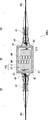
- FIG. 3 is a cross-sectional view illustrating the relay device for the submarine cable according to the second embodiment.
- the relay device REPn has a housing 40 and a cable coupling 50.
- the cable coupling 50 connects the optical fiber core wire LF1 and the optical fiber core wire LF2 when connecting the cable CB1 and the relay device REPn.
- the housing 40 is typically cylindrical and includes a plurality of optical amplifiers AM and a plurality of optical fiber core wires LF therein.
- the housing 40 is a pressure-resistant container, and includes a cylinder 41 on a side surface portion and an end face plate 42 of a top plate and a bottom plate corresponding to a lid.
- the end face plate 42 is penetrated by a special component called a feedthrough 43 for passing an optical fiber and a feeder line.
- the feedthrough 43 is a component through which an optical fiber and an electric wire are passed while withstanding a large pressure difference on both sides thereof.
- the pressure-resistant container is generally made of a metal material and has a telluric current because it is in contact with seawater.
- the electrical components inside the pressure-resistant container are sufficiently insulated from the earth potential, like the feeder line inside the submarine cable. Generally, this insulation (withstand voltage) is required to be 15 kV or more, and is realized by a sufficient gap provided between the inner wall of the pressure-resistant container and the internal device.
- the inside of the housing is generally filled with dry air.
- the submarine cable is disassembled inside the cable coupling 50, and the steel wire that realizes the cable tension is fastened with a fastener. Further, the optical fiber and the feeding line are connected to the optical fiber cord and the electric wire (collectively referred to as a tail cable 44) in the joint chamber 45.
- the tail cable 44 has the same water pressure resistance and withstand voltage performance as the submarine cable, but the strength protection is the minimum necessary because of the wiring material inside the device.
- the tail cable 44 is a component molded and manufactured integrally with the feedthrough 43 provided on the end face plate 42. That is, there is no connection point between the joint chamber 45 and the inside of the pressure resistant housing.
- the joint chamber 45 is the minimum structure for connecting while ensuring quality in an environment of high water pressure and high voltage difference.
- the joint chamber 45 has a structure in which a metal frame that protects the fusion splicing portion between optical fibers from water pressure and cable tension and the whole thereof are molded with polyethylene. Since no electronic component that generates heat is arranged in the joint chamber 45, it can be insulated by the polyethylene molding method.
- the portion inside the tail cable 44 is manufactured at the factory, and the end face plate 42 is weld-sealed and shipped. That is, the wiring inside the housing is fixed at this manufacturing stage, and it is impossible to add wiring after that. It is then transported to a submarine cable factory where it is connected to the submarine cable via a cable coupling 50. After that, it is loaded on a cable laying ship and laid on the seabed.
- connection component When connecting submarine cables on board, a connection component called a universal joint with a structure similar to that of the cable coupling 50 is used. In this way, unlike a land-based cable system, it is not easy for a submarine cable system to pull out a part of the optical fiber core wire LF or electric wire contained in the cable, and it is a structure with a withstand voltage structure and an insulating structure. Is required.
- the relay device REPn for the submarine cable has been described as an example, but the same device can be applied not only to the relay device REPn but also to a device having an amplification function for communication signals.
- FIG. 4 is a configuration diagram illustrating the optical communication cable system according to the third embodiment.
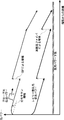
- FIG. 5 is a graph illustrating the transmission power of the probe light and the optical power of the Rayleigh scattered light received by the interrogator ITG in the optical communication cable system according to the third embodiment, and the horizontal axis is from the end station. The distance is shown and the vertical axis is the strength.
- the interrogator ITG and the excitation light source 60 are included in the wavelength selection coupler CPL at the terminal station 20 in the optical fiber core wire LF1 for sensing in the cable CB1. It is connected with. Further, an erbium-loaded fiber EDF and a high-scattering fiber 70 are inserted at appropriate positions in the optical fiber core wire LF1 for sensing in the cable CB1. For example, each of the erbium-added fiber EDF and the high-scattering fiber 70 is divided into sections in the optical fiber core wire LF1 where the light of the optical fiber sensing is attenuated.
- the excitation light source 60 outputs excitation light for exciting the distributed Raman amplification and the erbium-added fiber EDF.
- the erbium-added fiber EDF is an optical fiber core wire to which erbium is added, and has a function of absorbing excitation light and amplifying signal light.
- the high scattering fiber 70 is an optical fiber core wire LF having a large Rayleigh scattering coefficient. For example, a large number of scattered dots having a predetermined size are provided in the optical fiber core wire LF.
- the sensing distance can be extended by another step.
- the probe light PL and the backscattered light RL are distributed Raman amplified by the excitation light source 60 at a position near the terminal station 20.
- the probe light PL and Rayleigh scattered light are also amplified by the erbium-added fiber EDF. These optical amplifications extend the reach of the probe light PL and extend the Rayleigh scattered light generation points that can reach the interrogator ITG at a detectable level.
- the probe light PL is incident on the high scattering fiber 70, the generation efficiency of the Rayleigh scattered light is increased, so that the generation point of the Rayleigh scattered light that can reach the interrogator ITG at a detectable level is further extended.
- the sensingable distance can be extended to, for example, 160 km.
- a relay device for communication exists in the middle, the backscattered light generated after the relay device is blocked by the relay device, and the section beyond the relay device cannot be sensed.
- the relay devices REPn incorporating the through wiring of the second embodiment or the third embodiment are arranged along the cable CB1 at predetermined intervals. (Parts for communication signals in the relay device REPn are not shown.)
- the interrogator ITG transmits the backscattered light RL by the probe light PL transmitted over a long distance to each relay device REPn. Can be detected without being blocked by. Therefore, the optical fiber sensing system according to the present embodiment can further widen the sensing distance range and sense the information on the surrounding environment of the optical cable in a wide range.
- FIG. 6 is a configuration diagram illustrating the optical communication cable system according to the fourth embodiment. Only the difference from FIG. 2 will be described, and the same part will be omitted.
- the cable CB1 is not provided with the optical fiber core wire for sensing, and the optical signal for sensing is wavelength-multiplexed on one of the optical fiber core wires LF of the communication system.
- the optical fiber core wire LF1 for optical sensing is shared with the optical fiber core wire LF that transmits an optical signal for communication toward the end station 20 of the fiber pair FP13.
- the wavelength band of the optical signal for communication and the wavelength of the sensing light are assigned to each other so that they do not overlap.
- the input / output optical fiber of the interrogator ITG is connected to the optical fiber core wire LF transmitted toward the end station 20 of the fiber pair FP13 by a wavelength selection type optical coupler CPL.
- the combined probe optical PL is transmitted to the relay device REP1 in the opposite direction to the communication optical signal.
- the backscattered light RL transmitted through the optical fiber core wire LF transmitted toward the end station 20 of the fiber pair FP13 is wavelength-separated by the wavelength selection type optical coupler CPL and received by the interrogator ITG. ..
- the optical fiber core wire LF of the fiber pair FP13 in which the sensing light is wavelength-multiplexed is connected to the wavelength-selective optical coupler CPL, where the communication optical signal and the sensing light are wavelength-divided and demultiplexed.
- the sensing light is connected to the optical fiber core wire LF2 and propagates.
- the communication optical signal is connected to the optical amplifier AM and propagates.
- the port on the opposite side of the relay device REP1 is also mirrored as above. That is, the optical fiber core wire LF of the fiber pair FP13 in which the sensing light is wavelength-multiplexed is connected to the wavelength selection type optical coupler CPL, where the communication optical signal and the sensing light are wavelength-divided and demultiplexed.
- the sensing light is connected to the optical fiber core wire LF2 and propagates. Further, the optical signal for communication is connected to the optical amplifier and propagates.
- the communication optical signal is optically amplified by the optical amplifier, and the sensing light can pass around the amplifier.
- the communication optical signal is photoamplified, and the sensing light can pass around the amplifier AM.
- the amplification and detour described above are repeated within the measurable distance.
- the cable CB1 does not require a core wire for sensing. Therefore, this embodiment is suitable for retrofitting an existing communication cable with a sensing function.
- An optical fiber core wire for wavelength-multiplexing the sensing light is defined, and at the end station 20, a wavelength-selective optical coupler CPL is provided at the input / output port of the interrogator ITG to perform wavelength division multiplexing and demultiplexing, and a relay device within a sensingable distance.
- a wavelength selection type optical coupler CPL and a bypass optical fiber core wire LF2 may be added to the entrance and exit of one optical amplifier AM in REPn.
- the sensing function can be added without the need to redraw the cable CB1 and without reducing the communication optical fiber core wire LF.
- the fifth embodiment is an application example when the present technology is applied to a submarine cable system among optical communication cable systems.
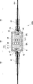
- FIG. 7 is a configuration diagram illustrating the optical communication cable system according to the fifth embodiment. Only the difference from FIG. 3 will be described, and the same part will be omitted.
- the optical fiber core wire LF2 is connected to the feedthrough 43 via the wavelength selection type optical coupler CPL and is connected to the outside of the housing 40. Further, the wavelength selection type optical coupler CPL couples and demultiplexes the communication optical signal and the sensing light.
- the submarine cable CB1 and the housing 40 of the relay device REPn are connected by a cable coupling 50.
- Such a relay device REPn for a submarine cable is managed by being divided into two types, one having an optical fiber core wire LF2 and a wavelength merging / demultiplexing coupler CPL for passing sensing light, and the other not having them. It's a little complicated. This can be a factor in increasing costs. Therefore, regardless of whether or not the sensing light is passed through, it is preferable to prepare the product with the optical fiber core wire LF2 and the wavelength merging / demultiplexing coupler CPL. Even if the relay device REPn is applied to a portion through which the sensing light does not pass, there is no problem other than the fact that the communication signal cannot be assigned to the wavelength assigned to the sensing light.
- the relay device REPn for the submarine cable has been described as an example, but the same device can be applied not only to the relay device REPn but also to a device having an amplification function for communication signals.
- FIG. 8 is a configuration diagram illustrating the optical communication cable system according to the sixth embodiment.
- the optical communication cable system 13 according to the present embodiment has a branching device BU1.
- the branching device BU1 is arranged between the terminal station 20 and the relay device REPn, or between the relay device REPn.
- the branching device BU1 branches the cable CB1 into the cable CB2 and the cable CB3.
- the branching device BU1 branches the cable CB1 including the fiber pairs FP11 to FP13 and the optical fiber core wire LF1 into the cable CB2 including the fiber pairs FP11 to FP13 and the cable CB3 including the optical fiber core wire LF1. To do.
- the branching device BU1 is a device that does not have an optical amplification function and does not require electric power. Inside the branching device BU1, the fiber pairs FP21 to FP23 for communication are through-connected. As a result, the branching device BU1 has almost no influence on the line design of the communication system, and the design is not complicated.
- the optical fiber core wire LF3 arranged in the branching device BU1 is connected to the optical fiber core wire LF1 in the sensing cable CB3.
- the optical fiber core wire LF3 of the present embodiment is a through wiring in the branching device BU1.
- the interrogator ITG sends the probe optical PL to the optical fiber core wire LF1 in the cable CB1, the optical fiber core wire LF3 in the branching device BU2, and the optical fiber core wire LF1 in the cable CB3, and reverses the route.
- the backward scattered light RL can be received at.
- This embodiment provides a cable branching configuration, the main effect of which is to separate the roles of the cables.
- Communication cables are generally laid on stable terrain routes with a low risk of failure.
- the sensing cable is not always laid on such a stable route, but depending on the monitoring target, it may be desired to lay it in a place where the terrain is unstable. In such a case, this embodiment is suitable.
- This embodiment is also suitable when the communication cable is installed first and then the branching device BU1 is inserted to branch the sensing cable. This is because the optical fiber core wire LF for communication in the branching device BU1 is a through connection, so that the influence on the communication system is minor. In that case, the cable between the interrogator ITG and the branching device BU1 is provided with a spare optical fiber core wire LF in advance.
- the cable branching device BU1 has been described in a configuration that does not have the optical amplifier AM, that is, has no function of the relay device REPn, but they may be integrated.
- FIG. 9 is an example of such a modification.
- the branching device BU2 includes a plurality of communication amplifiers AM, fiber pairs FP21 to FP23, and an optical fiber core wire LF3.
- Each amplifier AM is connected to each fiber pair FP11 to FP13 in the cable CB1 via each fiber pair FP21 to FP23.
- each amplifier AM amplifies and relays the wavelength division multiplexing communication light transmitted by the communication device COM arranged at the terminal station 20.
- the branching device BU2 since the branching device BU2 is provided with an optical amplifier AM inside, it may be further provided with a single-core bidirectional amplifier for the sensing core wire LF3 because it has a power supply.
- the single-core bidirectional amplifier AMM is inserted into the elliptical portion drawn by the dotted line.
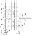
- FIG. 12 shows a typical realization example of the single-core bidirectional amplifier AMM.
- a circulator is used to separate the probe light PL and the backscattered light RL traveling in opposite directions, each is amplified by the optical amplifier AM, and then the circulator is used again to multiplex the probe light PL and the backscattered light RL in both directions.
- the optical bandpass filter is for removing noise light generated from the optical amplifier AM in a wavelength band other than the sensing light, and is inserted on the output side of the optical amplifier AM as needed.
- This amplifier AMM can amplify the probe light PL transmitted from the interrogator ITG and can amplify the backscattered light RL. Therefore, the loss between the end station 20 and the branching device BU2 can be compensated, and sensing can be performed along the cable CB3 to a longer distance.
- FIG. 10 is a configuration diagram illustrating the optical communication cable system according to the seventh embodiment.
- the optical communication cable system 14 according to the present embodiment has a branching device BU3.
- the branching device BU3 branches the cable CB1 including the fiber pairs FP11 to FP13 into the cable CB2 including the fiber pairs FP11 to FP13 and the cable CB3 including the optical fiber core wire LF1.
- the interrogator ITG and the branching device BU3 do not have the optical fiber core wire LF1 for sensing, and the optical fiber core wire LF 1 of the communication system is used for wavelength division multiplexing. This is the point where the optical signal for sensing is transmitted. That is, the optical fiber core wire LF1 for optical sensing is shared with any optical fiber core wire LF of the fiber pair FP13. In FIG. 10, the optical fiber core wire LF transmitted toward the end station 20 of the fiber pair FP13 is shared. The wavelength band of the optical signal for communication and the wavelength of the sensing light are assigned to each other so that they do not overlap.
- the input / output optical fiber core wire LF of the interrogator ITG is connected to the optical fiber core wire LF transmitted toward the end station 20 of the fiber pair FP13 by a wavelength selection type optical coupler CPL.
- the combined probe optical PL is transmitted to the branching device BU3 in the opposite direction to the communication signal.
- the backscattered light RL transmitted through the optical fiber core wire LF transmitted toward the terminal station 20 of the FP13 is wavelength-separated by the wavelength selection type optical coupler CPL and received by the interrogator ITG.
- the optical fiber core wire LF3 is separated from the optical fiber core wire LF of any of the fiber pair FP23 via the wavelength selection type optical coupler CPL.
- the separated optical fiber core wire LF3 is connected to the optical fiber core wire LF1 of the cable CB3.
- the optical fiber core wire LF3 of the present embodiment is a through wiring in the branching device BU3.
- the branching device BU3 is a device that does not have an optical amplification function and does not require electric power. Inside the branching device BU3, the fiber pairs FP21 to FP23 for communication are through-connected. As a result, the branching device BU3 has almost no influence on the line design of the communication system, and the design is not complicated.
- the main effect and purpose of this embodiment is to divide the roles of the cables by providing the cable branching configuration as described in the sixth embodiment. Further, in this configuration, even if the optical fiber core wire LF1 for sensing is not prepared in advance in the cable CB1 between the end station 20 and the branching device BU3, the branching device BU3 can be inserted to branch the sensing cable. Being able to do it is a big advantage. That is, it is possible to add a sensing function without having to re-draw the cable and without reducing the optical fiber core wire LF for communication.
- the cable branching device BU3 has been described in a configuration that does not have the optical amplifier AM, that is, has no function of the relay device REPn, but they may be integrated.
- FIG. 11 is an example of such a modification.
- the branching device BU4 includes a plurality of communication amplifiers AM, fiber pairs FP21 to FP23, and an optical fiber core wire LF3.
- Each amplifier AM is connected to each fiber pair FP11 to FP13 in the cable CB1 via each fiber pair FP21 to FP23.
- each amplifier AM amplifies and relays the wavelength division multiplexing communication light transmitted by the communication device COM arranged at the terminal station 20.
- the branching device BU4 since the branching device BU4 has an optical amplifier AM inside, it has a power supply, and therefore may further include a single-core bidirectional amplifier AMM for the sensing core wire LF3.
- the single-core bidirectional amplifier AMM is inserted into the elliptical portion drawn by the dotted line.
- FIG. 12 shows a typical realization example of the single-core bidirectional amplifier AMM. The operation description will be omitted. If this amplifier AMM is added, the loss between the end station 20 and the branching device BU4 can be compensated, and sensing can be performed along the cable CB3 to a longer distance.
- the interrogator ITG has been described with a network configuration installed at the terminal station of the communication system.
- the interrogator ITG is incorporated in, for example, the relay device REPn or the branching devices BU1 to BU4.
- the device of the present disclosure is applicable, and the effect can be obtained in the same manner.
- the distance of the optical fiber core wire LF1 for sensing included in the cable CB1 used for communication must be at least a distance exceeding the limit of the measurable distance of the interrogator ITG. There is, but it may have a longer distance. That is, both the relay device REPn and the cable CB1 may always be manufactured with an optical fiber core wire for sensing regardless of whether or not the cable CB1 is effectively used for sensing. As a result, the types can be integrated, the number of spare parts in case of failure can be halved, and the cost can be reduced. However, since there is an increase in the member cost for the additional optical fiber core wire LF, it may be selected by comparison with it.
- the present invention is not limited to the above embodiment, and can be appropriately modified without departing from the spirit.
- a combination of the configurations of the first to seventh embodiments is also within the scope of the technical idea of the embodiment.
- some or all of the above embodiments may be described as in the following appendix, but are not limited to the following.
- a relay device that is connected to a cable that includes one or more optical fiber cores that propagate optical signals for communication in an optical communication cable system, and has an optical amplification function that is interrupted to compensate for the transmission loss of the cable.
- the cable has an optical fiber sensing function that sends probe light to the optical fiber core wire in the cable by an interrogator, detects the backward scattered light of the probe light, and senses the environmental information around the cable.
- An optical wiring that allows the probe light and the backscattered light, which are the light of the optical fiber sensing, to pass through without passing through the optical amplifier.
- Relay device An optical wiring that allows the probe light and the backscattered light, which are the light of the optical fiber sensing, to pass through without passing through the optical amplifier.
- a housing including the optical amplifier is provided.
- the light of the fiber sensing includes a second optical fiber core wire which is the optical wiring for passing through the housing without passing through the optical amplifier.
- the first optical fiber core wire in the cable is connected to the second optical fiber core wire.
- the optical communication cable system is a submarine communication cable system.
- the relay device is a device structurally designed to be installed on the seabed.
- the wiring of the second optical fiber core wire for passing the light of the optical fiber sensing through the housing without passing through the optical amplifier is provided at the time of manufacturing the relay device.
- the first optical fiber core wire and the second optical fiber core wire are connected by a cable coupling portion.
- the relay device according to Appendix 2.
- the first optical fiber core wire in the cable is An optical fiber core wire section having a remote-excited optical amplification function, which is inserted into the portion where the light of the optical fiber sensing is attenuated, and An optical fiber with a large backscattering coefficient, which is inserted into the section where the light of the optical fiber sensing is attenuated, including, The relay device according to Appendix 2.
- the light of the optical fiber sensing and the optical signal for communication have different wavelengths from each other.
- the light of the optical fiber sensing is wavelength division multiplexing transmitted by one of the optical fiber core wires propagating the optical signal for communication in the cable.
- a wavelength division multiplexing device that multiplexes and separates the light of the optical fiber sensing and the optical signal for communication is provided in the housing.
- the light of the optical fiber sensing separated by the wavelength duplexer on the input side of the optical amplifier passes by bypassing the optical amplifier and then combined by the wavelength duplexer on the output side of the optical amplifier.
- the first optical fiber core wire in the cable is connected to the optical wiring in which the light of the optical fiber sensing in the housing and the optical signal for communication are wavelength-multiplexed.
- the relay device according to Appendix 1.
- the optical communication cable system is a submarine communication cable system.
- the housing is structurally designed to be installed on the seabed.
- the wavelength duplexer for allowing the light of the optical fiber sensing to pass through the housing of the relay device without passing through the optical amplifier, and the wiring of the second optical fiber core wire for detouring are provided at the time of manufacturing.
- Be When connecting the cable provided with the first optical fiber core wire to the relay device provided with the wavelength duplexer and the wiring of the second optical fiber core wire for detour.
- the first optical fiber core wire for optical fiber sensing and the second optical fiber core wire connected to the wavelength duplexer are connected by a cable coupling portion.
- the relay device according to Appendix 5.
- a branching device for branching the cable into a branching cable including the first optical fiber core wire is further provided. Inside the branching device, a through wiring for passing an optical signal for communication is provided.
- the relay device according to any one of Appendix 1 to 6.
- the branching device has the optical amplification function for amplifying the optical signal for communication.
- the cable between the interrogator and the branching device comprises the first optical fiber core.
- the branching device includes a second optical fiber core wire for allowing the light of the optical fiber sensing to pass through the housing of the branching device without passing through an optical amplifier.
- the first optical fiber core wire in the branch cable is connected to the second optical fiber core wire in the branching device.
- the relay device according to Appendix 7.
- the light for optical fiber sensing and the optical signal for communication have different wavelengths from each other.
- the light of the optical fiber sensing is wavelength division multiplexing transmission in one of the optical fiber core wires propagating the optical signal for communication in the cable.
- the light of the optical fiber sensing separated by the wavelength duplexer of the branching device is connected to the first optical fiber core wire in the branching cable.
- the branching device is a branching device integrated with the relay device having a function of amplifying an optical signal for communication.
- the light for optical fiber sensing and the optical signal for communication have different wavelengths from each other.
- the light of the optical fiber sensing is wavelength division multiplexing transmitted in one of the optical fiber core wires propagating the optical signal for communication in the cable.
- the light of the optical fiber sensing separated by the wavelength duplexer of the branching device is connected to the first optical fiber core wire in the branching cable without passing through the optical amplifier.
- the relay device according to Appendix 7.
- the optical communication cable system includes the cable including one or more optical fiber core wires for propagating an optical signal for communication, and a plurality of cables having an optical amplification function interrupted to compensate for the transmission loss of the cable.
- the probe light is sent to the optical fiber core wire in the cable to send the probe light.
- the probe light and the backscattered light which are the light of the optical fiber sensing, are passed through the optical amplifier without passing through the optical amplifier.
- a sensing method that detects backscattered light of the probe light and senses environmental information around the cable.
- the cable comprises a first fiber optic core for fiber optic sensing.
- the device having the optical amplification function includes a second optical fiber core wire which is the optical wiring for passing the light of the fiber sensing through the housing of the device without passing through the optical amplifier.
- the first optical fiber core wire in the cable is connected to the second optical fiber core wire in the device having the optical amplification function.
- the optical communication cable system is a submarine communication cable system, and the device is a device structurally designed to be installed on the seabed.
- Wiring of a second optical fiber core wire for passing the light of the optical fiber sensing through the housing of the device without passing through the optical amplifier is provided at the time of manufacturing the device having the optical amplification function.
- the first optical fiber core wire and the second optical fiber core wire are connected by a cable coupling portion.
- the light of the optical fiber sensing and the optical signal for communication are made to have different wavelengths from each other.
- the light of the optical fiber sensing is wavelength-division-multiplexed by one of the optical fiber core wires propagating the optical signal for communication in the cable.
- the device is provided with a wavelength division multiplexing device that multiplexes and separates the light of the optical fiber sensing and the optical signal for communication.
- the optical fiber sensing light separated by the wavelength duplexer on the input side of the optical amplifier passes by bypassing the optical amplifier, and then combined by the wavelength duplexer on the output side of the optical amplifier.
- the first optical fiber core wire in the cable is connected to the optical wiring in which the light of the optical fiber sensing and the optical signal for communication in the apparatus are wavelength-multiplexed.
- the optical communication cable system is a submarine communication cable system, and the device is a device structurally designed to be installed on the seabed.
- the wiring of the wavelength duplexer for allowing the light of the optical fiber sensing to pass through the housing of the device without passing through the optical amplifier and the wiring of the second optical fiber core wire for detouring is performed.
- the cable provided with the first optical fiber core wire to the device provided with the wavelength duplexer and the wiring of the second optical fiber core wire for detour.
- the first optical fiber core wire for optical fiber sensing and the second optical fiber core wire connected to the wavelength duplexer are connected by a cable coupling portion.
- An optical fiber sensing function is added to the cable of the optical communication cable system, and the cable system is further provided with a branching device for branching the cable into a branching cable including the first optical fiber core wire.
- a through wiring for passing the optical signal for communication is provided in the branching device.
- the branching device is a branching device integrated with the device having the optical amplification function for amplifying the optical signal for communication.
- the cable between the interrogator and the branching device is configured to include the first fiber optic core wire.
- the branching device is provided with a second optical fiber core wire for allowing the light of the optical fiber sensing to pass through the housing of the branching device without passing through the optical amplifier.
- the first optical fiber core wire in the branch cable is connected to the second optical fiber core wire in the integrated branching device.
- the light for optical fiber sensing and the optical signal for communication have different wavelengths from each other.
- the light of the optical fiber sensing is transmitted by wavelength division multiplexing in one of the optical fiber core wires for propagating the optical signal for communication in the cable. Let me The light of the optical fiber sensing separated by the wavelength duplexer of the branching device is connected to the first optical fiber core wire in the branching cable.
- the branching device is a branching device integrated with the device having the optical amplification function for amplifying the optical signal for communication.
- the light for optical fiber sensing and the optical signal for communication have different wavelengths from each other.
- the light of the optical fiber sensing is subjected to wavelength division multiplexing transmission at one of the optical fiber core wires propagating the optical signal for communication in the cable.
- the light of the optical fiber sensing separated by the wavelength duplexer of the branching device is connected to the first optical fiber core wire in the branching cable without passing through the optical amplifier.
- Excitation light source 70 High scattering fiber 111 Transponder group 121 Wavelength division multiplexing AM amplifier BU1 , BU2, BU3, BU4 Branching device CB1, CB2, CB3 Cable COM communication device CPL coupler DE detector EDF Elbium-added fiber FP1, FP2, FP11, FP12, FP13, FP21, FP22, FP23 Fiber pair ITG interrogator LF, LF1 , LF2, LF3 Optical fiber core line PL probe light RE receiver REPn, REP1, REP2 relay device RL rear scatter light SE transmitter SG optical signal
Landscapes
- Physics & Mathematics (AREA)
- General Physics & Mathematics (AREA)
- Optics & Photonics (AREA)
- Electromagnetism (AREA)
- Engineering & Computer Science (AREA)
- Computer Networks & Wireless Communication (AREA)
- Signal Processing (AREA)
- Optical Communication System (AREA)
- Light Guides In General And Applications Therefor (AREA)
- Arrangements For Transmission Of Measured Signals (AREA)
- Optical Transform (AREA)
Priority Applications (2)
| Application Number | Priority Date | Filing Date | Title |
|---|---|---|---|
| JP2021562459A JP7424391B2 (ja) | 2019-12-04 | 2020-09-14 | 光ファイバセンシングシステム、中継装置及びセンシング方法 |
| US17/778,907 US20220399938A1 (en) | 2019-12-04 | 2020-09-14 | Optical fiber sensing system, relay device, and sensing method |
Applications Claiming Priority (2)
| Application Number | Priority Date | Filing Date | Title |
|---|---|---|---|
| JP2019219922 | 2019-12-04 | ||
| JP2019-219922 | 2019-12-04 |
Publications (1)
| Publication Number | Publication Date |
|---|---|
| WO2021111699A1 true WO2021111699A1 (ja) | 2021-06-10 |
Family
ID=76221892
Family Applications (1)
| Application Number | Title | Priority Date | Filing Date |
|---|---|---|---|
| PCT/JP2020/034644 Ceased WO2021111699A1 (ja) | 2019-12-04 | 2020-09-14 | 光ファイバセンシングシステム、中継装置及びセンシング方法 |
Country Status (3)
| Country | Link |
|---|---|
| US (1) | US20220399938A1 (https=) |
| JP (1) | JP7424391B2 (https=) |
| WO (1) | WO2021111699A1 (https=) |
Cited By (1)
| Publication number | Priority date | Publication date | Assignee | Title |
|---|---|---|---|---|
| WO2026048476A1 (ja) * | 2024-08-29 | 2026-03-05 | 株式会社オーシーシー | 遠隔励起を用いた光増幅中継システム |
Families Citing this family (3)
| Publication number | Priority date | Publication date | Assignee | Title |
|---|---|---|---|---|
| WO2021111691A1 (ja) * | 2019-12-03 | 2021-06-10 | 日本電気株式会社 | 光ファイバセンシングシステム、測定装置及び測定方法 |
| EP4677776A1 (en) * | 2023-03-10 | 2026-01-14 | BAE SYSTEMS plc | Apparatus and method |
| WO2025010267A1 (en) * | 2023-07-05 | 2025-01-09 | Subcom, Llc | Monitoring in distributed acoustic sensing systems |
Citations (5)
| Publication number | Priority date | Publication date | Assignee | Title |
|---|---|---|---|---|
| JPH09214425A (ja) * | 1996-02-05 | 1997-08-15 | Nec Corp | 通信・観測融合海底ケーブルシステム |
| JP2001345759A (ja) * | 2000-06-02 | 2001-12-14 | Mitsubishi Electric Corp | 光中継装置 |
| US20160259083A1 (en) * | 2013-10-17 | 2016-09-08 | Halliburton Energy Services, Inc. | Distributed sensing in an optical fiber network |
| JP2017194306A (ja) * | 2016-04-19 | 2017-10-26 | 三菱重工業株式会社 | 光ファイバセンシングシステム及びライザー管 |
| JP2019518968A (ja) * | 2016-06-23 | 2019-07-04 | オプタセンス・ホールデイングス・リミテツド | 光ファイバセンシング |
Family Cites Families (19)
| Publication number | Priority date | Publication date | Assignee | Title |
|---|---|---|---|---|
| JPS6161038A (ja) * | 1984-08-31 | 1986-03-28 | Nippon Telegr & Teleph Corp <Ntt> | 通信用ケ−ブル保守方式 |
| JP3100386B2 (ja) * | 1990-06-19 | 2000-10-16 | 住友電気工業株式会社 | 光通信システム |
| JPH04285835A (ja) * | 1991-03-14 | 1992-10-09 | Fujikura Ltd | 光ファイバ通信線路の特性検出方法または特性検出装置 |
| JP2782124B2 (ja) * | 1991-07-05 | 1998-07-30 | 株式会社フジクラ | 光ファイバケーブル |
| JPH0546144U (ja) * | 1991-11-14 | 1993-06-18 | 日立電線株式会社 | 光通信システム |
| JPH05241030A (ja) * | 1992-02-27 | 1993-09-21 | Sumitomo Electric Ind Ltd | 分布型光ファイバセンサ |
| JPH08256106A (ja) * | 1995-03-17 | 1996-10-01 | Fujitsu Ltd | 光増幅海底伝送システムの分散補償装置 |
| JPH09210847A (ja) * | 1996-02-06 | 1997-08-15 | Furukawa Electric Co Ltd:The | 光伝送システムにおける光中継器の監視方法とそれに用いられる光中継器 |
| AU747525B2 (en) * | 1998-12-18 | 2002-05-16 | Future Fibre Technologies Pty Ltd | Apparatus and method for monitoring a structure using a counter-propagating signal method for locating events |
| US8634713B2 (en) * | 2008-08-29 | 2014-01-21 | Telefonaktiebolaget Lm Ericsson (Publ) | Fibre monitoring in optical networks |
| CN101995320B (zh) * | 2009-08-27 | 2012-03-21 | 华为海洋网络有限公司 | 检测水下设备故障的方法、装置及设备 |
| US8328431B2 (en) * | 2010-02-01 | 2012-12-11 | Tyco Electronics Subsea Communications Llc | Coupling multiple conductor undersea optical cables to an undersea device with an isolated bypass conductive path across the undersea device |
| JP5298043B2 (ja) * | 2010-02-15 | 2013-09-25 | 日本電信電話株式会社 | 光ケーブル敷設環境測定方法、光ケーブル敷設環境測定装置及び光ケーブル敷設環境測定システム |
| US9410866B2 (en) * | 2012-08-29 | 2016-08-09 | Telefonaktiebolaget L M Ericsson (Publ) | Device for monitoring an optical fibre |
| EP2819321A1 (en) * | 2013-06-27 | 2014-12-31 | Alcatel Lucent | Packet optical add drop multiplexing node for an optical ring network |
| JP2015200728A (ja) * | 2014-04-07 | 2015-11-12 | 富士通株式会社 | 光分岐器、光増幅装置及び光増幅方法 |
| GB201421470D0 (en) * | 2014-12-03 | 2015-01-14 | Silixa Ltd | Range extension for optical fiber sensing systems |
| CN107925475A (zh) * | 2015-08-03 | 2018-04-17 | 日本电气株式会社 | 光分插设备和光分插方法 |
| JP7115182B2 (ja) * | 2018-09-25 | 2022-08-09 | 日本電信電話株式会社 | 光コネクタ用フェルール、スリーブ及びフェルール部材製造方法 |
-
2020
- 2020-09-14 JP JP2021562459A patent/JP7424391B2/ja active Active
- 2020-09-14 WO PCT/JP2020/034644 patent/WO2021111699A1/ja not_active Ceased
- 2020-09-14 US US17/778,907 patent/US20220399938A1/en not_active Abandoned
Patent Citations (5)
| Publication number | Priority date | Publication date | Assignee | Title |
|---|---|---|---|---|
| JPH09214425A (ja) * | 1996-02-05 | 1997-08-15 | Nec Corp | 通信・観測融合海底ケーブルシステム |
| JP2001345759A (ja) * | 2000-06-02 | 2001-12-14 | Mitsubishi Electric Corp | 光中継装置 |
| US20160259083A1 (en) * | 2013-10-17 | 2016-09-08 | Halliburton Energy Services, Inc. | Distributed sensing in an optical fiber network |
| JP2017194306A (ja) * | 2016-04-19 | 2017-10-26 | 三菱重工業株式会社 | 光ファイバセンシングシステム及びライザー管 |
| JP2019518968A (ja) * | 2016-06-23 | 2019-07-04 | オプタセンス・ホールデイングス・リミテツド | 光ファイバセンシング |
Cited By (1)
| Publication number | Priority date | Publication date | Assignee | Title |
|---|---|---|---|---|
| WO2026048476A1 (ja) * | 2024-08-29 | 2026-03-05 | 株式会社オーシーシー | 遠隔励起を用いた光増幅中継システム |
Also Published As
| Publication number | Publication date |
|---|---|
| JP7424391B2 (ja) | 2024-01-30 |
| JPWO2021111699A1 (https=) | 2021-06-10 |
| US20220399938A1 (en) | 2022-12-15 |
Similar Documents
| Publication | Publication Date | Title |
|---|---|---|
| WO2021111699A1 (ja) | 光ファイバセンシングシステム、中継装置及びセンシング方法 | |
| US12235139B2 (en) | Cable system | |
| US12111204B2 (en) | Extending dynamic acoustic sensing range and localization in undersea cables using loopbacks | |
| CN102100019A (zh) | 支持检测和通信网络的光通信系统 | |
| EP2897310A1 (en) | Method and system for monitoring infrastructure using BOTDA | |
| JPWO2021111699A5 (https=) | ||
| JP5387311B2 (ja) | 波長多重光ネットワークシステム及び波長多重光の送受信方法 | |
| EP0499388B1 (en) | Bidirectional optical fibre communication link incorporating an amplifier | |
| CN105103024B (zh) | 光纤完整性监控 | |
| US7218442B2 (en) | Optical communications system with fiber break detection in the presence of Raman amplification | |
| US12072243B2 (en) | Monitoring device, monitoring method, and optical transmission system | |
| JP7347538B2 (ja) | 光ファイバセンシングシステム、測定装置及び測定方法 | |
| JPWO2021111691A5 (https=) | ||
| JP7750451B2 (ja) | 電力ケーブル、電力線路、電力ケーブルの異常点検出システム、および電力ケーブルの異常点検出方法 | |
| US12571673B2 (en) | Multi-span optical fiber das system with amplified-filtered loopback (AFLB) | |
| WO2019244660A1 (ja) | 光増幅器、光伝送システム及び光ケーブル障害個所測定方法 | |
| US20230283366A1 (en) | Environment information acquisition system, environment information acquisition method, and recording medium | |
| EP4262109B1 (en) | Optical communication link with remote optically pumped amplifier | |
| JP7778276B2 (ja) | 光通信システム | |
| JP7721049B1 (ja) | 光通信システム | |
| GB2281463A (en) | Optical transmission system |
Legal Events
| Date | Code | Title | Description |
|---|---|---|---|
| 121 | Ep: the epo has been informed by wipo that ep was designated in this application |
Ref document number: 20894983 Country of ref document: EP Kind code of ref document: A1 |
|
| ENP | Entry into the national phase |
Ref document number: 2021562459 Country of ref document: JP Kind code of ref document: A |
|
| NENP | Non-entry into the national phase |
Ref country code: DE |
|
| 122 | Ep: pct application non-entry in european phase |
Ref document number: 20894983 Country of ref document: EP Kind code of ref document: A1 |