WO2021111647A1 - 蓄電デバイスの発火防止装置 - Google Patents
蓄電デバイスの発火防止装置 Download PDFInfo
- Publication number
- WO2021111647A1 WO2021111647A1 PCT/JP2020/004940 JP2020004940W WO2021111647A1 WO 2021111647 A1 WO2021111647 A1 WO 2021111647A1 JP 2020004940 W JP2020004940 W JP 2020004940W WO 2021111647 A1 WO2021111647 A1 WO 2021111647A1
- Authority
- WO
- WIPO (PCT)
- Prior art keywords
- power storage
- storage device
- ignition
- ignition prevention
- storage devices
- Prior art date
- Legal status (The legal status is an assumption and is not a legal conclusion. Google has not performed a legal analysis and makes no representation as to the accuracy of the status listed.)
- Ceased
Links
Images

Classifications
-
- H—ELECTRICITY
- H01—ELECTRIC ELEMENTS
- H01G—CAPACITORS; CAPACITORS, RECTIFIERS, DETECTORS, SWITCHING DEVICES, LIGHT-SENSITIVE OR TEMPERATURE-SENSITIVE DEVICES OF THE ELECTROLYTIC TYPE
- H01G11/00—Hybrid capacitors, i.e. capacitors having different positive and negative electrodes; Electric double-layer [EDL] capacitors; Processes for the manufacture thereof or of parts thereof
- H01G11/10—Multiple hybrid or EDL capacitors, e.g. arrays or modules
-
- H—ELECTRICITY
- H01—ELECTRIC ELEMENTS
- H01G—CAPACITORS; CAPACITORS, RECTIFIERS, DETECTORS, SWITCHING DEVICES, LIGHT-SENSITIVE OR TEMPERATURE-SENSITIVE DEVICES OF THE ELECTROLYTIC TYPE
- H01G11/00—Hybrid capacitors, i.e. capacitors having different positive and negative electrodes; Electric double-layer [EDL] capacitors; Processes for the manufacture thereof or of parts thereof
- H01G11/14—Arrangements or processes for adjusting or protecting hybrid or EDL capacitors
-
- H—ELECTRICITY
- H01—ELECTRIC ELEMENTS
- H01M—PROCESSES OR MEANS, e.g. BATTERIES, FOR THE DIRECT CONVERSION OF CHEMICAL ENERGY INTO ELECTRICAL ENERGY
- H01M50/00—Constructional details or processes of manufacture of the non-active parts of electrochemical cells other than fuel cells, e.g. hybrid cells
- H01M50/20—Mountings; Secondary casings or frames; Racks, modules or packs; Suspension devices; Shock absorbers; Transport or carrying devices; Holders
-
- H—ELECTRICITY
- H01—ELECTRIC ELEMENTS
- H01M—PROCESSES OR MEANS, e.g. BATTERIES, FOR THE DIRECT CONVERSION OF CHEMICAL ENERGY INTO ELECTRICAL ENERGY
- H01M50/00—Constructional details or processes of manufacture of the non-active parts of electrochemical cells other than fuel cells, e.g. hybrid cells
- H01M50/30—Arrangements for facilitating escape of gases
-
- Y—GENERAL TAGGING OF NEW TECHNOLOGICAL DEVELOPMENTS; GENERAL TAGGING OF CROSS-SECTIONAL TECHNOLOGIES SPANNING OVER SEVERAL SECTIONS OF THE IPC; TECHNICAL SUBJECTS COVERED BY FORMER USPC CROSS-REFERENCE ART COLLECTIONS [XRACs] AND DIGESTS
- Y02—TECHNOLOGIES OR APPLICATIONS FOR MITIGATION OR ADAPTATION AGAINST CLIMATE CHANGE
- Y02E—REDUCTION OF GREENHOUSE GAS [GHG] EMISSIONS, RELATED TO ENERGY GENERATION, TRANSMISSION OR DISTRIBUTION
- Y02E60/00—Enabling technologies; Technologies with a potential or indirect contribution to GHG emissions mitigation
- Y02E60/10—Energy storage using batteries
Definitions
- the present invention relates to a device for preventing ignition caused by gas ejected from a module of a power storage device such as a lithium ion battery, a lithium ion capacitor, or an electric double layer capacitor, and particularly to a gas ejected from a module composed of a plurality of power storage devices.
- the present invention relates to an ignition prevention device capable of efficiently suppressing ignition.
- Such a power storage device usually has an upper limit voltage, and is controlled so as not to exceed the upper limit voltage by combining with an appropriate protection circuit. However, if the protection circuit malfunctions and exceeds the upper limit voltage, if charging / discharging is repeated, or if a short circuit occurs due to an external factor, the power storage device falls into an overcharged state, and the electrolytic solution becomes an electrode material or the like. A gas is generated by the reaction, and the generated gas raises the internal pressure. This generated gas may contain flammable gases such as methane, carbon monoxide, ethylene, ethane, and propane, and when released to the outside of the power storage device, there is a risk of ignition, explosion, or the like.
- flammable gases such as methane, carbon monoxide, ethylene, ethane, and propane
- power storage devices such as lithium ion capacitors and electric double layer capacitors have been required to have higher output and higher capacity, and are based on a single power storage device or a module configuration in which a plurality of power storage devices are stacked.
- Opportunities to use it with large currents are increasing. For example, in a module in which a plurality of power storage devices are stacked, if one power storage device falls into an overcharged state, the other power storage devices are still functioning even after the gas is released together with the electrolytic solution. The current may continue to flow. Therefore, the short circuit may cause severe overheating, and the risk of ignition, explosion, etc. as described above increases.
- Patent Documents As a technique capable of preventing ignition of such a power storage device, for example, a method of absorbing gas generated inside a lithium ion battery with a flammable gas absorber to prevent the battery from exploding has been proposed (Patent Documents). 1, 2).
- Patent Document 3 a method has also been proposed in which a fire extinguishing agent is placed inside the lithium-ion battery to reduce the temperature of the gas released to the outside when the safety valve is opened due to an increase in the internal pressure due to the generation of gas inside the battery.
- the flammable gas has a predetermined gas concentration, an ignition temperature, and an ignition temperature for the occurrence of ignition (for example, the ignition temperature is 537 ° C for methane, 605 ° C for carbon monoxide, and 530 for hydrogen. °C, 520 °C with ethane, etc.). Therefore, oxygen and sparks are required for ignition to occur when the temperature of the flammable gas is below the ignition point.
- Patent Document 4 regarding the flammable gas generated from the power storage device, the flammable gas is adsorbed to reduce the concentration thereof, and the latent heat of vaporization of water is used to lower the temperature of the flammable gas.
- a technique for suppressing ignition is disclosed.
- Patent Document 4 for lowering the temperature of the flammable gas to suppress ignition is also provided in the limited space of the power storage device, so that the amount of gas adsorbed and the gas adsorption rate Both are inadequate, and there is a problem that if the concentration of the combustible gas cannot be kept below the combustible concentration, the gas may ignite even at a temperature lower than the ignition point if a fire type exists. Furthermore, since the flammable gas components generated depending on the ignition conditions such as ignition due to damage, ignition due to heating, and ignition due to overcharging are different, there is also a problem that the ignition suppression effect is greatly increased depending on the gas adsorption characteristics of the adsorbent. is there.
- the present invention has been made in view of the above problems, and there is a risk of ignition in the event of an abnormality such as damage or overcharging of a power storage device, particularly an aggregate of a plurality of power storage devices, to a spark or a spark. It is an object of the present invention to provide an ignition prevention device for a power storage device that can act and suppress.
- the present invention is an ignition prevention device for a power storage device installed outside the internal gas discharge port of the power storage device, and is discharged from the internal gas discharge port of the power storage device into a breathable casing.
- an ignition prevention device for a power storage device which is filled with a flame suppressant for ignition and / or flame of a flammable gas (Invention 1).
- a material having at least one of the ability to absorb flammable gas, the ability to lower the temperature, and the ability to extinguish a flame is used outside the internal gas discharge port of the power storage device to ignite and / or extinguish the flammable gas.
- a breathable casing as a flame suppressant
- the flammable gas released from the internal gas discharge port of the power storage device comes into contact with the suppressant in this breathable casen, thereby making the flammable gas flammable.
- Ignition and flame of flammable gas can be suppressed by the effect of lowering the gas concentration, lowering the temperature, or extinguishing the flame itself.
- the flammable gas that may be generated from the power storage device contains methane, carbon monoxide, ethylene, ethane or propane (Invention 2).
- invention 2 by bringing these flammable gases into contact with an inhibitor, the concentration of the flammable gas is lowered, the temperature is lowered, or the flame itself is extinguished, resulting in the combustible gas. It is possible to suppress ignition and flame and greatly reduce the risk of spreading the fire to the outside.
- the power storage device uses a non-aqueous electrolyte (Invention 3).
- the non-aqueous electrolyte may generate a flammable gas by heating. Therefore, by bringing this flammable gas into contact with an inhibitor, the concentration of the flammable gas can be reduced. By lowering the temperature or extinguishing the flame itself, it is possible to suppress the ignition and flame of flammable gas and greatly reduce the risk of spreading the fire to the outside.
- the inhibitor is an inorganic porous material (Invention 4).
- the inorganic porous material is zeolite (Invention 5).
- the inorganic porous material particularly zeolite, has an ability to lower the concentration of the flammable gas, lower the temperature, or extinguish the flame itself, so that the flammable gas can be ignited.
- the flame can be suppressed and the risk of spreading the fire to the outside can be significantly reduced.
- the inhibitor is a carbon-based material (Invention 6).
- the carbon-based material since the carbon-based material has an ability to reduce the concentration of the flammable gas, lower the temperature, or extinguish the flame itself, it suppresses the ignition and flame of the flammable gas. The risk of fire spreading to the outside can be significantly reduced.
- the inhibitor is a porous material having an average particle size of 1 to 30 mm (Invention 7).
- the flow resistance of the flammable gas can be reduced, and the concentration of the flammable gas can be effectively reduced. It can exert the ability to lower the temperature or extinguish the flame itself.
- the power storage device is an aggregate of two or more power storage devices, and one ignition prevention device of the power storage device extends over the internal gas outlets of the plurality of power storage devices. It is preferable that it can be installed (Invention 8).
- an aggregate provided with a plurality of power storage devices allows a large current to flow because the other power storage devices are functioning even when one power storage device falls into an overcharged state. As it continues, it is overheated violently and flammable gas tends to exceed the ignition temperature. At this time, even if the flammable gas is ejected from any of the power storage devices and flows out into the space of the casing, the concentration of the flammable gas is lowered, the temperature is lowered, or the temperature is lowered by configuring the structure so as to come into contact with the inhibitor. Since the flame itself can be extinguished, the ignition of flammable gas and the flame can be suppressed, and the risk of spreading the fire to the outside can be significantly reduced.
- the present invention provides an ignition prevention device for a power storage device in which a flammable gas discharged from an internal gas discharge port of the power storage device is filled with a flame suppressant and / or a flame suppressant in a breathable casing to release the internal gas of the power storage device. Since it is installed outside the outlet, the flammable gas released from the internal gas discharge port of the power storage device comes into contact with the inhibitor in this breathable casing, so that the concentration of the flammable gas is lowered and the temperature is lowered. Or, by the effect of extinguishing the flame itself, it is possible to suppress the ignition and flame of flammable gas.
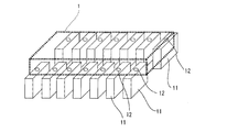
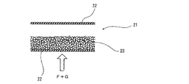
- FIG. 1 It is a perspective view which shows the ignition prevention device of the power storage device by one Embodiment of this invention. It is a vertical cross-sectional view schematically showing the ignition prevention device of the power storage device according to the same embodiment. It is the schematic which shows the test apparatus of Examples 1 to 3.
- the ignition prevention device of the power storage device of the present invention will be described in detail based on the following embodiments.
- the ignition prevention device 1 of the power storage device of the present embodiment is installed on the internal gas discharge port 12 formed in the power storage device 11 as shown in FIG.
- the ignition prevention device 1 of the power storage device is a breathable casing in which a metal mesh member 22 is attached to the upper surface and the lower surface of a heat-resistant plastic or metal side peripheral frame member (not shown). It has a structure in which 21 is filled with a granular (pellet) flammable gas ignition and / or flame inhibitor 23.
- the power storage device 11 is a plurality of aggregates, and the ignition prevention device 1 of the power storage device is installed so as to cover the internal gas discharge ports 12 of the plurality of power storage devices 11.
- the power storage device 11 is not particularly limited, and either a primary battery or a secondary battery can be used, but a secondary battery is preferable.
- the type of this secondary battery is not particularly limited, and for example, a lithium ion battery, a lithium ion polymer battery, a lead livestock battery, a nickel / hydrogen livestock battery, a nickel / cadmium livestock battery, a nickel / iron livestock battery, and a nickel / zinc.
- a livestock battery, a silver oxide / zinc livestock battery, a metal air battery, a polyvalent cation battery, a capacitor, a capacitor and the like can be used. Among these, those using a non-aqueous electrolyte can be preferably used.
- these secondary batteries it can be suitably applied to lithium ion batteries, lithium ion polymer batteries, lithium ion capacitors and the like.
- non-aqueous electrolyte in the power storage device 11 examples include cyclic carbonates such as propylene carbonate (PC) and ethylene carbonate (EC), and dimethyl carbonate (DMC), ethyl methyl carbonate (EMC), diethyl carbonate (DEC) and the like.
- PC propylene carbonate
- EC ethylene carbonate
- DMC dimethyl carbonate
- EMC ethyl methyl carbonate
- DEC diethyl carbonate
- a mixed solution with chain carbonate or the like can be used.
- the non-aqueous electrolyte may be one in which a lithium salt such as lithium hexafluorophosphate is dissolved as an electrolyte, if necessary.
- a mixed solution of ethylene carbonate (EC), ethyl methyl carbonate (EMC) and dimethyl carbonate (DMC) in a ratio of 1: 1: 1, or propylene carbonate (PC), ethylene carbonate (EC), diethyl carbonate (A mixture prepared by mixing DEC) at a ratio of 1: 1: 1 to which 1 mol / L lithium hexafluorophosphate is added can be used.
- the inhibitor 23 that suppresses the ignition and / or flame of the flammable gas generated due to the non-aqueous electrolyte of the power storage device 11 is one of the flammable gas absorbing ability, the temperature lowering ability, and the flame extinguishing ability.
- a porous material may be preferably used as long as it is provided with two or more.
- an organic material, an inorganic material, or an organic / inorganic composite material can be used, and in particular, an inorganic porous material, a carbon-based porous material, an organic host compound, and a porous organic metal composite can be used. Materials and the like can be preferably used.
- the inorganic porous material examples include porous silica, metallic porous structure, calcium silicate, magnesium silicate, magnesium aluminometasilicate, zeolite, active alumina, titanium oxide, apatite, porous glass, magnesium oxide, and aluminum silicate. Etc. can be used.
- activated carbon such as powdered activated carbon, granular activated carbon, fibrous activated carbon, and sheet-shaped activated carbon, graphite, carbon black, carbon nanotubes, carbon molecular sieve, fullerene, nanocarbon, and the like can be used.
- the magnesium silicate a mixture of silicon oxide such as silicon dioxide and magnesium oxide as an alkaline earth metal oxide can be used.
- inorganic porous materials and carbon-based materials may be used alone or in combination of two or more kinds of materials, but these inorganic porous materials are a mixture of zeolite, activated carbon, silicon dioxide and magnesium oxide.
- the carbon-based material may be used alone, or two or more kinds of materials may be used in combination, but zeolite, activated carbon, and magnesium silicate (including a mixture of silicon dioxide and magnesium oxide) are particularly effective. ..
- the form of the inhibitor 23 as described above is not particularly limited and may be in the form of powder, granules or pellets (including chips and granules), but the size is such that it does not pass through the mesh member 22.
- the average particle size may be 1 to 30 mm, particularly 3 to 20 mm, which is larger than the size of the sieve of the mesh member 22. If the size of the inhibitor is less than 1 mm, the gas permeability of the power storage device 11 is low, so that flammable gas and flames do not easily pass through, and it becomes easy to avoid the power storage device 11, while if it exceeds 30 mm, the flammable gas It becomes difficult to efficiently exert absorption ability, temperature lowering ability, and flame extinguishing ability. From these things, it is preferable to make it in the form of pellets.
- the filling rate of the inhibitor 23 into the casing 21 (apparent filling rate depending on the region filled with the inhibitor 23) is too small, the ability to absorb flammable gas, the ability to lower the temperature, and the ability to extinguish a flame are efficient.
- the amount is too large, the fluidity of the inhibitor 23 in the casing 21 is impaired, resulting in resistance to the flow of flammable gas and flames. Since it becomes difficult to efficiently exert the flame extinguishing ability, it may be about 20 to 70% by volume.
- the size of the casing 21 and the filling amount of the suppressing agent 23 depend on the number of power storage devices 11 in which the ignition prevention device 1 is installed, the assumed amount of flammable gas, and the capacity of the suppressing agent 23. It may be set appropriately.
- the ignition prevention device 1 of the power storage device is installed so as to cover the internal gas discharge ports 12 of the plurality of power storage devices 11, 11 ... If the power storage device 11 is used in this state, flammable gas may be generated if any of the power storage devices 11 is damaged during use, overcharged, or deteriorated due to repeated charging / discharging. is there. This flammable gas is discharged from the internal gas discharge port 12, and if sparks are present due to a short circuit or overheating of the circuit at this time, the flammable gas is ignited and becomes a flame.
- the ignition prevention device 1 of the power storage device are metal mesh members 22 having air permeability, these flammable gas G and flame F are contained in the ignition prevention device 1 as shown in FIG. It invades and comes into contact with the inhibitor 23. At this time, since the inhibitor 23 has the ability to absorb the flammable gas G and / or the ability to lower the temperature of the flammable gas G and / or the flame extinguishing ability, the flame is caused by a decrease in the concentration of the flammable gas G or a decrease in temperature. The fire will be extinguished or the flame F will be extinguished directly. The soot and dust generated by the combustion of the flammable gas G also enter the power storage device 11 and are captured. As a result, the flammable gas G and the flame F are not diffused into the external environment from the ignition prevention device 1 of the power storage device, so that it is possible to prevent a fire caused by the failure of the power storage device 11.
- the present invention is not limited to the present embodiment, and the size, shape, and shape of the ignition prevention device 1 for the power storage device.
- the means for imparting breathability is not particularly limited, and the device can be applied to a wide range of sizes of power storage devices 11 such as smartphones and vehicles.
- the ignition prevention device does not need to be provided in close contact with the internal gas discharge port 12 of the power storage device 11, and may be separated from the tip of the internal gas discharge port 12 by about 5 cm or less.
- a lithium ion battery 33 (PL-703562-2C, 3.7V, 1500mAh) is used as a power storage device in a closed container 31 having a volume of 1.7L in which an internal gas discharge port 32 having a diameter of 13 mm ⁇ is formed. ), And the positive electrode 34 and the negative electrode 35 were connected to a charging / discharging device (not shown), respectively.
- Metal nets 43 and 44 of 7 to 12 mesh are pasted on the upper and lower surfaces of a metal frame 42 having an outer dimension of 300 mm ⁇ 150 mm and an inner dimension of 250 mm ⁇ 110 mm ⁇ 30 mm, and the inside thereof is filled with an inhibitor 23. Then, the ignition prevention device 41 was used.
- the ignition prevention device 41 is not filled with the inhibitor 23, but is installed at a distance of 3 cm from the internal gas discharge port 32, and the lithium ion battery 33 is overcharged at 5C (15V, 7.5Ah). At this time, the temperature of the lithium ion battery 33 (LiB temperature), the maximum outlet temperature of the internal gas discharge port 32, and the maximum top surface temperature of the ignition prevention device 41 were measured. The results are shown in Table 1.
- Examples 1 to 3 In the reference example, the ignition prevention device 41, the inhibitor 23, the zeolite pellet (Epsiguard EP-102 manufactured by Kurita Kogyo Co., Ltd.), and the zeolite pellet (Epsiguard EP-103 manufactured by Kurita Kogyo Co., Ltd.) ), And pellets of a mixture of silicon dioxide and magnesium oxide are filled in the amounts shown in Table 1, the lithium ion battery 33 is in an overcharged state, and the lithium ion battery 33 is exploded and ignited. , The maximum outlet temperature of the internal gas discharge port 32, and the maximum top surface temperature of the ignition prevention device 41 were measured. The results are shown in Table 1 together with the inhibitor and filling amount.
- Ignition prevention device for power storage device 11
- Power storage device Internal gas discharge port 21
- Casing 22
- Metal mesh member 23
- Suppressant 29
- Sealed container 32
- Internal gas discharge port 33
- Lithium-ion battery (power storage device) 34
- Negative electrode 41
- Frame body 43, 44 Net (mesh member)
Landscapes
- Engineering & Computer Science (AREA)
- Power Engineering (AREA)
- Microelectronics & Electronic Packaging (AREA)
- Chemical & Material Sciences (AREA)
- Chemical Kinetics & Catalysis (AREA)
- Electrochemistry (AREA)
- General Chemical & Material Sciences (AREA)
- Electric Double-Layer Capacitors Or The Like (AREA)
- Battery Mounting, Suspending (AREA)
- Gas Exhaust Devices For Batteries (AREA)
- Secondary Cells (AREA)
Abstract
蓄電デバイスの発火防止装置1は、蓄電デバイス11に形成された内部ガス放出口12上に設置される。この蓄電デバイスの発火防止装置1は、耐熱性プラスチックあるいは金属製の側周枠部材の上面及び下面に金属製のメッシュ部材を貼設した通気性を有するケーシング内に粒状(ペレット)の可燃性ガスの発火及び/又は火炎の抑制剤を充填した構造を有する。そして、蓄電デバイス11は複数の集合体であり、蓄電デバイスの発火防止装置1は、これら複数の蓄電デバイス11の内部ガス放出口12をそれぞれ覆うように設置されている。このような蓄電デバイスの発火防止装置によれば、蓄電デバイス、特に複数の蓄電デバイスを積層した蓄電デバイススタックの破損や過充電等の異常時に発火するリスクを火種や火花にも作用して抑制することができる。
Description
本発明は、リチウムイオン電池、リチウムイオンキャパシタ、電気二重層キャパシタ等の蓄電デバイスのモジュールから噴出するガスに起因する発火の防止装置に関し、特に複数の蓄電デバイスからなるモジュールから噴出するガスに起因する発火を効率的に抑制することの可能な発火防止装置に関する。
近年、高出力用途の携帯機器、パソコン、電気自動車等の電源として、非水電解質を用いた蓄電デバイスをケーシングに収容してなる二次電池、リチウムイオンキャパシタ及び電気二重層キャパシタ等の蓄電デバイスが用いられている。
このような蓄電デバイスは、通常、上限電圧が定められており、適切な保護回路と組み合わせることで上限電圧を超えないよう制御されている。しかしながら、保護回路が誤動作を起こし上限電圧を超えた場合、充放電の繰り返した場合、あるいは外的要因により短絡した場合等には、蓄電デバイスは過充電状態に陥り、電解液が電極材料等と反応してガスが発生し、この発生したガスによって内圧が上昇する。この発生するガスは、メタン、一酸化炭素、エチレン、エタン、プロパン等の可燃性ガスを含むことがあり、蓄電デバイス外部に放出された際に、発火、爆発等を起こす危険性がある。
そして、近年、リチウムイオンキャパシタや電気二重層キャパシタ等の蓄電デバイスにおいては、さらなる高出力及び高容量化が求められてきており、蓄電デバイス単体や、複数の蓄電デバイスをスタックしたモジュール構成のもと大電流で使用する機会が増えてきている。例えば、複数の蓄電デバイスをスタックしたモジュールにおいて、一つの蓄電デバイスが過充電状態に陥った場合には、ガスが電解液と共に放出された後も、その他の蓄電デバイスが機能しているため、大電流を流し続けることがある。そのため短絡により、激しく過熱される場合があり、上述したような発火、爆発等を起こす危険性は大きくなる。
このような蓄電デバイスの発火を防止し得る技術として、例えば、リチウムイオン電池の内部で発生したガスを可燃性ガス吸収材によって吸収し、電池の破裂を防止する方法が提案されている(特許文献1,2)。
一方、リチウムイオン電池内部に消火剤を配置することにより、電池内部でのガスの発生による内圧上昇により安全弁が開放した際に外部に放出されるガスの温度を低下する方法も提案されている(特許文献3)。
また、リチウムイオン電池において発火が発現するには、火花(火種)と空気(酸素)、可燃性ガスの三つの要因が関係する。ここで可燃性ガスは、発火が発現するための所定のガス濃度と引火温度と発火温度とがそれぞれ決まっている(例えば、発火温度はメタンで537℃、一酸化炭素で605℃、水素で530℃、エタンで520℃等)。このため、可燃性ガスの温度が発火点以下で発火が発現するためには、酸素と火花が必要となる。そこで、特許文献4には、蓄電デバイスから発生して可燃性ガスに関し、該可燃性ガスを吸着してその濃度を低下させるとともに、水分の蒸発潜熱を利用して、可燃性ガスの温度を低下させて発火を抑制する技術が開示されている。
しかしながら、蓄電デバイスでは、電気的異常時や、熱暴走時は瞬間的に大量のガスが発生するが、特許文献1及び2に記載されているようなガス吸着材を蓄電デバイス内に配置する方法では、蓄電デバイスという限られた空間に対しては、ガス吸着量及びガス吸着速度ともに不十分であり、蓄電デバイスからのガスの噴出を抑制しきれない、という問題点があった。また、特許文献3に記載されているようにリチウムイオン電池の内部の温度を低下させるために消火剤や、多孔質素材の細孔内及び表面に不燃性ガスあるいは水系溶媒または不燃性溶媒を吸着される材を蓄電デバイス内に配置する方法では、ガス吸着量が不十分だと、その効果が十分に発揮されず、さらにガスの噴出を抑制しきれない、という問題点があった。
さらに、特許文献4に記載されている可燃性ガスの温度を低下させて発火を抑制する技術においても、やはり蓄電デバイスという限られた空間に設けられるものであるので、ガス吸着量及びガス吸着速度ともに不十分であり、可燃ガスの燃焼するする濃度以下にできなければ、火種が存在すると発火点より低い温度でも発火してしまうおそれがある、という問題点があった。さらに、破損による発火、加熱による発火、過充電による発火等、発火条件により発生する可燃性ガス成分が相違するため、吸着剤のガス吸着特性によって、発火抑制効果が大きくことなる、という問題点もある。
本発明は、上記課題に鑑みてなされたものであり、蓄電デバイス、特に複数の蓄電デバイスの集合体のいずれかの蓄電デバイスの破損や過充電等の異常時に発火するリスクを火種や火花にも作用して抑制することが可能な蓄電デバイスの発火防止装置を提供することを目的とする。
上記課題を解決するために本発明は、蓄電デバイスの内部ガス放出口の外側に設置される蓄電デバイスの発火防止装置であって、通気性を有するケーシングに前記蓄電デバイスの内部ガス放出口から吐出する可燃性ガスの発火及び/又は火炎の抑制剤を充填した、蓄電デバイスの発火防止装置を提供する(発明1)。
上記発明(発明1)によれば、蓄電デバイスの内部ガス放出口の外側に可燃性ガスの吸収能、温度低下能、火炎消火能の少なくともいずれかを有する素材を可燃性ガスの発火及び/又は火炎の抑制剤として、通気性を有するケーシングに充填してやることで、蓄電デバイスの内部ガス放出口から放出された可燃性ガスは、この通気性ケーシン内で抑制剤に接触することにより、該可燃性ガスの濃度の低下、温度の低下、あるいは火炎自体の消火の効果により、可燃性ガスの発火や火炎を抑制することができる。
上記発明(発明1)においては、前記蓄電デバイスから発生する可能性のある可燃性ガスが、メタン、一酸化炭素、エチレン、エタン又はプロパンを含有することが好ましい(発明2)。
上記発明(発明2)によれば、これらの可燃性ガスを抑制剤に接触させることで、当該可燃性ガスの濃度の低下、温度の低下、あるいは火炎自体の消火の効果により、可燃性ガスの発火や火炎を抑制して、外部にまで延焼するリスクを大幅に低減することができる。
上記発明(発明1,2)においては、前記蓄電デバイスが非水電解質を用いたものであることが好ましい(発明3)。
上記発明(発明3)によれば、非水電解質は加熱により、可燃性ガスを発生する虞があるので、この可燃性ガスを抑制剤に接触させることで、該可燃性ガスの濃度の低下、温度の低下、あるいは火炎自体の消火の効果により、可燃性ガスの発火や火炎を抑制して、外部にまで延焼するリスクを大幅に低減することができる。
上記発明(発明1~3)においては、前記抑制剤が、無機多孔質材料であることが好ましい(発明4)。特に上記発明(発明4)においては、前記無機多孔質材料がゼオライトであることが好ましい(発明5)。
かかる発明(発明4,5)によれば、無機多孔質材料、特にゼオライトは、可燃性ガスの濃度の低下、温度の低下、あるいは火炎自体を消火する能力を有するので、可燃性ガスの発火や火炎を抑制して、外部にまで延焼するリスクを大幅に低減することができる。
また、上記発明(発明1~3)においては、前記抑制剤が、炭素系材料であることが好ましい(発明6)。
かかる発明(発明6)によれば、炭素系材料は、可燃性ガスの濃度の低下、温度の低下、あるいは火炎自体を消火する能力を有するので、可燃性ガスの発火や火炎を抑制して、外部にまで延焼するリスクを大幅に低減することができる。
上記発明(発明1~6)においては、前記抑制剤が1~30mmの平均粒子径を有する多孔質素材であることが好ましい(発明7)。
上記発明(発明7)によれば、抑制剤をある程度の粒径を有する多孔質素材とすることにより、可燃性ガスの流通抵抗を小さくすることができ、効果的に可燃性ガスの濃度の低下、温度の低下、あるいは火炎自体を消火する能力を発揮することができる。
上記発明(発明1~7)においては、前記蓄電デバイスが、2つ以上の蓄電デバイスの集合体であり、1つの前記蓄電デバイスの発火防止装置が、複数の蓄電デバイスの内部ガス放出口上にわたって設置可能となっていることが好ましい(発明8)。
上記発明(発明8)によれば、蓄電デバイスを複数備えた集合体は、1つの蓄電デバイスが過充電状態に陥った場合であってもその他の蓄電デバイスが機能しているため大電流を流し続けるので、激しく過熱され、可燃性のガスが発火温度以上となりやすい。このとき、いずれかの蓄電デバイスから可燃性ガスが噴出してケーシングの空間に流出したとしても、抑制剤と接触するように構成することで、可燃性ガスの濃度の低下、温度の低下、あるいは火炎自体を消火する能力を発揮することができるので、可燃性ガスの発火や火炎を抑制して、外部にまで延焼するリスクを大幅に低減することができる。
本発明は、蓄電デバイスの内部ガス放出口から吐出する可燃性ガスの発火及び/又は火炎の抑制剤を、通気性を有するケーシングに充填した蓄電デバイスの発火防止装置を、蓄電デバイスの内部ガス放出口の外側に設置するので、蓄電デバイスの内部ガス放出口から放出された可燃性ガスは、この通気性ケーシング内で抑制剤に接触することにより、該可燃性ガスの濃度の低下、温度の低下、あるいは火炎自体の消火の効果により、可燃性ガスの発火や火炎を抑制することができる。
本発明の蓄電デバイスの発火防止装置について、以下の実施形態に基づき詳細に説明する。
[蓄電デバイスの発火防止装置]
本実施形態の蓄電デバイスの発火防止装置1は、図1に示すように蓄電デバイス11に形成された内部ガス放出口12上に設置されるものである。この蓄電デバイスの発火防止装置1は、図2に示すように図示しない耐熱性プラスチックあるいは金属製の側周枠部材の上面及び下面に金属製のメッシュ部材22をそれぞれ貼設した通気性を有するケーシング21内に粒状(ペレット)の可燃性ガスの発火及び/又は火炎の抑制剤23を充填した構造を有する。そして、本実施形態においては、蓄電デバイス11は複数の集合体であり、蓄電デバイスの発火防止装置1は、これら複数の蓄電デバイス11の内部ガス放出口12をそれぞれ覆うように設置されている。
本実施形態の蓄電デバイスの発火防止装置1は、図1に示すように蓄電デバイス11に形成された内部ガス放出口12上に設置されるものである。この蓄電デバイスの発火防止装置1は、図2に示すように図示しない耐熱性プラスチックあるいは金属製の側周枠部材の上面及び下面に金属製のメッシュ部材22をそれぞれ貼設した通気性を有するケーシング21内に粒状(ペレット)の可燃性ガスの発火及び/又は火炎の抑制剤23を充填した構造を有する。そして、本実施形態においては、蓄電デバイス11は複数の集合体であり、蓄電デバイスの発火防止装置1は、これら複数の蓄電デバイス11の内部ガス放出口12をそれぞれ覆うように設置されている。
(蓄電デバイス)
本実施形態において、蓄電デバイス11としては、特に制限はなく、一次電池、二次電池のいずれも用いることができるが、好ましくは二次電池である。この二次電池の種類については、特に制限されず、例えば、リチウムイオン電池、リチウムイオンポリマー電池、鉛畜電池、ニッケル・水素畜電池、ニッケル・カドミウム畜電池、ニッケル・鉄畜電池、ニッケル・亜鉛畜電池、酸化銀・亜鉛畜電池、金属空気電池、多価カチオン電池、コンデンサ、キャパシタ等を用いることができる。これらの中では、非水電解質を用いたものを好適に用いることができる。これらの二次電池の中でも、リチウムイオン電池、リチウムイオンポリマー電池、リチウムイオンキャパシタ等に好適に適用することができる。
本実施形態において、蓄電デバイス11としては、特に制限はなく、一次電池、二次電池のいずれも用いることができるが、好ましくは二次電池である。この二次電池の種類については、特に制限されず、例えば、リチウムイオン電池、リチウムイオンポリマー電池、鉛畜電池、ニッケル・水素畜電池、ニッケル・カドミウム畜電池、ニッケル・鉄畜電池、ニッケル・亜鉛畜電池、酸化銀・亜鉛畜電池、金属空気電池、多価カチオン電池、コンデンサ、キャパシタ等を用いることができる。これらの中では、非水電解質を用いたものを好適に用いることができる。これらの二次電池の中でも、リチウムイオン電池、リチウムイオンポリマー電池、リチウムイオンキャパシタ等に好適に適用することができる。
上記蓄電デバイス11における非水電解質としては、例えば、プロピレンカーボネート(PC)、エチレンカーボネート(EC)等の環状カーボネートと、ジメチルカーボネート(DMC)、エチルメチルカーボネート(EMC)、ジエチルカーボネート(DEC)等の鎖状カーボネートとの混合溶液等を用いることができる。また、上記非水電解質は、必要に応じて、電解質として六フッ化リン酸リチウム等のリチウム塩が溶解したものであってもよい。例えば、エチレンカーボネート(EC)、エチルメチルカーボネート(EMC)及びジメチルカーボネート(DMC)を1:1:1の割合で混合した混合液、あるいはプロピレンカーボネート(PC)、エチレンカーボネート(EC)、ジエチルカーボネート(DEC)を1:1:1の割合で混合した混合液に、1mol/Lの六フッ化リン酸リチウムを添加したものを用いることができる。
(可燃性ガスの発火及び/又は火炎の抑制剤)
このような蓄電デバイス11の非水電解質等に起因して発生する可燃性ガスの発火及び/又は火炎を抑制する抑制剤23は、可燃性ガスの吸収能、温度低下能及び火炎消火能の1又は2以上を備えたものであればよく、多孔質素材を好適に用いることができる。本実施形態において多孔質素材としては、有機系、無機系、あるいは有機・無機複合素材を用いることができ、特に、無機多孔質素材料、炭素系多孔質素材、有機ホスト化合物、多孔質有機金属複合材料等を好適に用いることができる。
このような蓄電デバイス11の非水電解質等に起因して発生する可燃性ガスの発火及び/又は火炎を抑制する抑制剤23は、可燃性ガスの吸収能、温度低下能及び火炎消火能の1又は2以上を備えたものであればよく、多孔質素材を好適に用いることができる。本実施形態において多孔質素材としては、有機系、無機系、あるいは有機・無機複合素材を用いることができ、特に、無機多孔質素材料、炭素系多孔質素材、有機ホスト化合物、多孔質有機金属複合材料等を好適に用いることができる。
無機多孔質材料としては、多孔質シリカ、金属ポーラス構造体、ケイ酸カルシウム、ケイ酸マグネシウム、メタケイ酸アルミン酸マグネシウム、ゼオライト、活性アルミナ、酸化チタン、アパタイト、多孔質ガラス、酸化マグネシウム、ケイ酸アルミニウム等を用いることができる。炭素系材料としては、粉末状活性炭、粒状活性炭、繊維状活性炭、シート状活性炭等の活性炭、グラファイト、カーボンブラック、カーボンナノチューブ、カーボンモレキュラシーブ、フラーレン、ナノカーボン等を用いることができる。また、ケイ酸マグネシウムとしては、二酸化ケイ素等の酸化ケイ素とアルカリ土類金属酸化物として酸化マグネシウムとを混合したものを用いることができる。
これらの無機多孔質材料及び炭素系材料は単独で用いてもよいし、二種類以上の素材を併用してもよいが、ゼオライト、活性炭、二酸化ケイ素と酸化マグネシウムとの混合 これらの無機多孔質材料及び炭素系材料は単独で用いてもよいし、二種類以上の素材を併用してもよいが、ゼオライト、活性炭、ケイ酸マグネシウム(二酸化ケイ素と酸化マグネシウムとの混合物を含む)が特に有効である。
上述したような抑制剤23の形態は特に制限はなく、粉末状、顆粒状もしくはペレット状(チップ状、粒状を含む)とすることができるが、メッシュ部材22を通過しない大きさとする。具体的には、メッシュ部材22のふるいの大きさ以上で、1~30mm、特に3~20mm程度の平均粒子径とすればよい。抑制剤の大きさが1mm未満では、蓄電デバイス11の気体透過性が低いため、可燃性ガスや火炎が通過しにくくなり、蓄電デバイス11を回避しやすくなる一方、30mmを超えると可燃性ガスの吸収能、温度低下能及び火炎消火能を効率的に発揮しにくくなる。これらのことからペレット状とすることが好ましい。
また、抑制剤23のケーシング21内への充填率(抑制剤23が満たされている領域によるみかけの充填率)は、少なすぎると可燃性ガスの吸収能、温度低下能及び火炎消火能を効率的に発揮しにくくなる一方、多すぎると抑制剤23のケーシング21内での流動性が損なわれることにより、可燃性ガスや火炎の流通抵抗となり、かえって可燃性ガスの吸収能、温度低下能及び火炎消火能を効率的に発揮しにくくなることから、20~70容積%程度とすればよい。また、ケーシング21の大きさ、及び抑制剤23の充填量は、発火防止装置1が設置される蓄電デバイス11の個数と、想定される可燃性ガスの量と、抑制剤23の能力とに応じて、適宜設定すればよい。
[蓄電デバイスの発火防止方法]
上述したような発火防止装置1による蓄電デバイス11の発火防止方法について、以下説明する。まず、図1に示すように複数の蓄電デバイス11,11・・・の各内部ガス放出口12上を覆うように蓄電デバイスの発火防止装置1を設置する。この状態で蓄電デバイス11を使用すると、使用中にいずれかの蓄電デバイス11が破損したり、過充電されたり、あるいは充放電の繰り返しに伴い劣化したりすると、可燃性のガスが発生することがある。この可燃性ガスは、内部ガス放出口12から放出し、この際回路の短絡や過熱により火花が存在すると、可燃性ガスに引火して火炎となる。
上述したような発火防止装置1による蓄電デバイス11の発火防止方法について、以下説明する。まず、図1に示すように複数の蓄電デバイス11,11・・・の各内部ガス放出口12上を覆うように蓄電デバイスの発火防止装置1を設置する。この状態で蓄電デバイス11を使用すると、使用中にいずれかの蓄電デバイス11が破損したり、過充電されたり、あるいは充放電の繰り返しに伴い劣化したりすると、可燃性のガスが発生することがある。この可燃性ガスは、内部ガス放出口12から放出し、この際回路の短絡や過熱により火花が存在すると、可燃性ガスに引火して火炎となる。
そして、蓄電デバイスの発火防止装置1の上面及び下面は通気性を有する金属製のメッシュ部材22であるので、図2に示すようにこれら可燃性ガスG及び火炎Fは、発火防止装置1内に侵入し、抑制剤23に接触する。このとき抑制剤23は、可燃性ガスGの吸収能及び/又は可燃性ガスGの温度低下能及び/又は火炎消火能を有するので、可燃性ガスGの濃度の低下あるいは温度の低下により火炎は鎮火するか、あるいは火炎Fが直接消火されることになる。なお、可燃性ガスGの燃焼に伴い発生する煤塵も蓄電デバイス11内に侵入し、捕捉されることになる。これらにより、可燃性ガスG及び火炎Fは蓄電デバイスの発火防止装置1より外部環境に拡散することがなくなるので、蓄電デバイス11の障害にともなう火災を防止することができる。
以上、本発明の蓄電デバイスの発火防止装置について一つの実施形態に基づき説明してきたが、本発明は本実施形態に限定されるものではなく、蓄電デバイスの発火防止装置1の大きさ、形状、通気性を付与するための手段等は特に制限されず、スマートフォンから車載用等、幅広い大きさの蓄電デバイス11に適用可能である。また、発火防止装置は、蓄電デバイス11の内部ガス放出口12上に密着して設ける必要はなく、5cm以下程度内部ガス放出口12の先端から離間していてもよい。
以下の具体的実施例に基づき本発明をさらに詳細に説明するが、本発明は下記の実施例に限定されるものではない。
(試験装置)
試験装置として、図3に示すように直径13mmΦの内部ガス放出口32を形成した容積1.7Lの密閉容器31内に蓄電デバイスとしてリチウムイオン電池33(PL-703562-2C,3.7V,1500mAh)を収容し、正極34及び負極35をそれぞれ充放電装置(図示せず)接続した。
試験装置として、図3に示すように直径13mmΦの内部ガス放出口32を形成した容積1.7Lの密閉容器31内に蓄電デバイスとしてリチウムイオン電池33(PL-703562-2C,3.7V,1500mAh)を収容し、正極34及び負極35をそれぞれ充放電装置(図示せず)接続した。
(発火防止装置)
外寸300mm×150mmで内寸250mm×110mm×30mmの金属製の枠体42の上面及び下面に7~12メッシュの金属製の網43,44を貼設し、この内部に抑制剤23を充填して、発火防止装置41とした。
外寸300mm×150mmで内寸250mm×110mm×30mmの金属製の枠体42の上面及び下面に7~12メッシュの金属製の網43,44を貼設し、この内部に抑制剤23を充填して、発火防止装置41とした。
(参考例)
発火防止装置41に抑制剤23を充填せずに、内部ガス放出口32から3cm離間して設置し、リチウムイオン電池33を5C(15V,7.5Ah)で過充電状態として、リチウムイオン電池33を爆発・発火させ、この際のリチウムイオン電池33の温度(LiB温度)と、内部ガス放出口32の最高出口温度と、発火防止装置41の最高上面温度とを測定した。結果を表1に示す。
発火防止装置41に抑制剤23を充填せずに、内部ガス放出口32から3cm離間して設置し、リチウムイオン電池33を5C(15V,7.5Ah)で過充電状態として、リチウムイオン電池33を爆発・発火させ、この際のリチウムイオン電池33の温度(LiB温度)と、内部ガス放出口32の最高出口温度と、発火防止装置41の最高上面温度とを測定した。結果を表1に示す。
(実施例1~3)
参考例において、発火防止装置41に、抑制剤23にゼオライト系ペレット(栗田工業(株)製 イプシガードEP-102)、ゼオライト系ペレット(栗田工業(株)製 栗田工業(株)製 イプシガードEP-103)、及び二酸化ケイ素と酸化マグネシウムの混合物のペレットとを表1に示す量で充填し、リチウムイオン電池33を過充電状態として、リチウムイオン電池33を爆発・発火させ、この際のリチウムイオン電池33の温度と、内部ガス放出口32の最高出口温度と、発火防止装置41の最高上面温度とを測定した。結果を抑制剤及び充填量とともに表1に示す。
参考例において、発火防止装置41に、抑制剤23にゼオライト系ペレット(栗田工業(株)製 イプシガードEP-102)、ゼオライト系ペレット(栗田工業(株)製 栗田工業(株)製 イプシガードEP-103)、及び二酸化ケイ素と酸化マグネシウムの混合物のペレットとを表1に示す量で充填し、リチウムイオン電池33を過充電状態として、リチウムイオン電池33を爆発・発火させ、この際のリチウムイオン電池33の温度と、内部ガス放出口32の最高出口温度と、発火防止装置41の最高上面温度とを測定した。結果を抑制剤及び充填量とともに表1に示す。

表1から明らかなように、参考例では、リチウムイオン電池33から発生する可燃性ガスに引火し、可燃性ガスの放出する間は発火が持続したのに対し、実施例1~3の発火防止装置41によれば、可燃性ガスが吸着されるととともに温度が低下するため、発火が抑制されることが確認できた。
1 蓄電デバイスの発火防止装置
11 蓄電デバイス
12 内部ガス放出口
21 ケーシング
22 金属製のメッシュ部材
23 抑制剤
31 密閉容器
32 内部ガス放出口
33 リチウムイオン電池(蓄電デバイス)
34 正極
35 負極
41 発火防止装置
42 枠体
43,44 網(メッシュ部材)
11 蓄電デバイス
12 内部ガス放出口
21 ケーシング
22 金属製のメッシュ部材
23 抑制剤
31 密閉容器
32 内部ガス放出口
33 リチウムイオン電池(蓄電デバイス)
34 正極
35 負極
41 発火防止装置
42 枠体
43,44 網(メッシュ部材)
Claims (8)
- 蓄電デバイスの内部ガス放出口の外側に設置される蓄電デバイスの発火防止装置であって、通気性を有するケーシングに前記蓄電デバイスの内部ガス放出口から吐出する可燃性ガスの発火及び/又は火炎の抑制剤を充填した、蓄電デバイスの発火防止装置。
- 前記蓄電デバイスから発生する可能性のある可燃性ガスが、メタン、一酸化炭素、エチレン、エタン又はプロパンを含有する、請求項1に記載の蓄電デバイスの発火防止装置。
- 前記蓄電デバイスが非水電解質を用いたものである、請求項1又は2に記載の蓄電デバイスの発火防止装置。
- 前記抑制剤が、無機多孔質材料である、請求項1~3のいずれか1項に記載の蓄電デバイスの発火防止装置。
- 前記無機多孔質材料がゼオライトである、請求項4に記載の蓄電デバイスの発火防止装置。
- 前記抑制剤が、炭素系材料である、請求項1~3のいずれか1項に記載の蓄電デバイスの発火防止装置。
- 前記抑制剤が1~30mmの平均粒子径を有する多孔質素材である、請求項1~6のいずれか1項に記載の蓄電デバイスの発火防止装置。
- 前記蓄電デバイスが、2つ以上の蓄電デバイスの集合体であり、1つの前記蓄電デバイスの発火防止装置が、複数の蓄電デバイスの内部ガス放出口上にわたって設置可能となっている、請求項1~7のいずれか1項に記載の蓄電デバイスの発火防止装置。
Applications Claiming Priority (2)
| Application Number | Priority Date | Filing Date | Title |
|---|---|---|---|
| JP2019-221092 | 2019-12-06 | ||
| JP2019221092A JP7532769B2 (ja) | 2019-12-06 | 2019-12-06 | 発火防止装置付き蓄電ユニット |
Publications (1)
| Publication Number | Publication Date |
|---|---|
| WO2021111647A1 true WO2021111647A1 (ja) | 2021-06-10 |
Family
ID=76220702
Family Applications (1)
| Application Number | Title | Priority Date | Filing Date |
|---|---|---|---|
| PCT/JP2020/004940 Ceased WO2021111647A1 (ja) | 2019-12-06 | 2020-02-07 | 蓄電デバイスの発火防止装置 |
Country Status (2)
| Country | Link |
|---|---|
| JP (1) | JP7532769B2 (ja) |
| WO (1) | WO2021111647A1 (ja) |
Families Citing this family (2)
| Publication number | Priority date | Publication date | Assignee | Title |
|---|---|---|---|---|
| JP7679821B2 (ja) * | 2022-10-21 | 2025-05-20 | トヨタ自動車株式会社 | ラミネート型電池 |
| KR20240137751A (ko) * | 2023-03-09 | 2024-09-20 | 주식회사 엘지에너지솔루션 | 내화 코팅층이 탈리되어 벤팅홀이 개방되는 배터리 모듈 |
Citations (3)
| Publication number | Priority date | Publication date | Assignee | Title |
|---|---|---|---|---|
| WO2012029669A1 (ja) * | 2010-09-02 | 2012-03-08 | 株式会社Gsユアサ | 電池及び電池システム |
| JP2013187089A (ja) * | 2012-03-08 | 2013-09-19 | Kurita Water Ind Ltd | 蓄電デバイスの発火防止材、この発火防止材を含む発火防止システム、およびこの発火防止システムを用いた蓄電システム |
| DE102016102969A1 (de) * | 2016-02-19 | 2017-08-24 | Thomas Forchert | Anordnung mit einer galvanischen Zelle und gemeinsamer Transportbehälter |
Family Cites Families (1)
| Publication number | Priority date | Publication date | Assignee | Title |
|---|---|---|---|---|
| JP6390062B2 (ja) * | 2014-12-08 | 2018-09-19 | 三菱重工業株式会社 | 電池モジュール |
-
2019
- 2019-12-06 JP JP2019221092A patent/JP7532769B2/ja active Active
-
2020
- 2020-02-07 WO PCT/JP2020/004940 patent/WO2021111647A1/ja not_active Ceased
Patent Citations (3)
| Publication number | Priority date | Publication date | Assignee | Title |
|---|---|---|---|---|
| WO2012029669A1 (ja) * | 2010-09-02 | 2012-03-08 | 株式会社Gsユアサ | 電池及び電池システム |
| JP2013187089A (ja) * | 2012-03-08 | 2013-09-19 | Kurita Water Ind Ltd | 蓄電デバイスの発火防止材、この発火防止材を含む発火防止システム、およびこの発火防止システムを用いた蓄電システム |
| DE102016102969A1 (de) * | 2016-02-19 | 2017-08-24 | Thomas Forchert | Anordnung mit einer galvanischen Zelle und gemeinsamer Transportbehälter |
Also Published As
| Publication number | Publication date |
|---|---|
| JP2021089885A (ja) | 2021-06-10 |
| JP7532769B2 (ja) | 2024-08-14 |
Similar Documents
| Publication | Publication Date | Title |
|---|---|---|
| Liu et al. | Experimental study on the efficiency of dodecafluoro-2-methylpentan-3-one on suppressing lithium-ion battery fires | |
| KR102628827B1 (ko) | 전지 박스 및 그 제조 방법, 전지 박스를 포함하는 장치 | |
| Russo et al. | Effective fire extinguishing systems for lithium-ion battery | |
| JP5338331B2 (ja) | 電池パック、それを備えた電子機器 | |
| CN110660945A (zh) | 一种防止热失控蔓延的电池组 | |
| JP5222496B2 (ja) | リチウムイオン二次電池 | |
| WO2016015603A1 (zh) | 锂电池和应用该锂电池的电动交通工具 | |
| CN104218193A (zh) | 一种具有防火防爆装置的锂电池及应用该电池的电动车 | |
| CN203983375U (zh) | 安全阀及包含该安全阀的电池及电池模组 | |
| JP7532769B2 (ja) | 発火防止装置付き蓄電ユニット | |
| CN112768819A (zh) | 一种高消防安全的储能电池包与储能电池集装箱 | |
| JP2015135749A (ja) | リチウムイオン電池、及びこれを用いた電子機器 | |
| JP2026067921A (ja) | 発火リスク低減用蓄電デバイス構造体 | |
| JP2022133893A (ja) | 蓄電デバイス構造体 | |
| JP7364019B1 (ja) | 蓄電デバイス構造体 | |
| CN204271170U (zh) | 一种安全锂离子电池组 | |
| CN114159717B (zh) | 锂离子电池热失控抑制剂组合物、锂离子电池热失控抑制剂及制备方法和应用、锂离子电池 | |
| KR20150091898A (ko) | 안전성이 향상된 리튬 이차전지 모듈 및 리튬 이차전지 팩 | |
| JP2001332237A (ja) | 電池装置 | |
| CN116368679A (zh) | 二次电池和包括该二次电池的二次电池模块 | |
| JP2021012865A (ja) | 蓄電デバイス構造体 | |
| KR20160004247A (ko) | 안전성이 향상된 리튬 이차전지 모듈 및 리튬 이차전지 팩 | |
| CN205429053U (zh) | 一种锂电池组件阻燃防爆装置 | |
| JP2022169370A (ja) | 蓄電デバイス構造体 | |
| Un et al. | Thermal runaway and fire suppression for electric vehicle batteries |
Legal Events
| Date | Code | Title | Description |
|---|---|---|---|
| NENP | Non-entry into the national phase |
Ref country code: DE |
|
| 122 | Ep: pct application non-entry in european phase |
Ref document number: 20896134 Country of ref document: EP Kind code of ref document: A1 |