WO2021100602A1 - 送信装置、受信装置、および伝送システム - Google Patents
送信装置、受信装置、および伝送システム Download PDFInfo
- Publication number
- WO2021100602A1 WO2021100602A1 PCT/JP2020/042254 JP2020042254W WO2021100602A1 WO 2021100602 A1 WO2021100602 A1 WO 2021100602A1 JP 2020042254 W JP2020042254 W JP 2020042254W WO 2021100602 A1 WO2021100602 A1 WO 2021100602A1
- Authority
- WO
- WIPO (PCT)
- Prior art keywords
- unit
- transmission
- data
- payload
- rate
- Prior art date
- Legal status (The legal status is an assumption and is not a legal conclusion. Google has not performed a legal analysis and makes no representation as to the accuracy of the status listed.)
- Ceased
Links
Images






Classifications
-
- H—ELECTRICITY
- H04—ELECTRIC COMMUNICATION TECHNIQUE
- H04N—PICTORIAL COMMUNICATION, e.g. TELEVISION
- H04N21/00—Selective content distribution, e.g. interactive television or video on demand [VOD]
- H04N21/60—Network structure or processes for video distribution between server and client or between remote clients; Control signalling between clients, server and network components; Transmission of management data between server and client, e.g. sending from server to client commands for recording incoming content stream; Communication details between server and client
- H04N21/63—Control signaling related to video distribution between client, server and network components; Network processes for video distribution between server and clients or between remote clients, e.g. transmitting basic layer and enhancement layers over different transmission paths, setting up a peer-to-peer communication via Internet between remote STB's; Communication protocols; Addressing
- H04N21/647—Control signaling between network components and server or clients; Network processes for video distribution between server and clients, e.g. controlling the quality of the video stream, by dropping packets, protecting content from unauthorised alteration within the network, monitoring of network load, bridging between two different networks, e.g. between IP and wireless
- H04N21/64784—Data processing by the network
-
- H—ELECTRICITY
- H04—ELECTRIC COMMUNICATION TECHNIQUE
- H04N—PICTORIAL COMMUNICATION, e.g. TELEVISION
- H04N21/00—Selective content distribution, e.g. interactive television or video on demand [VOD]
- H04N21/60—Network structure or processes for video distribution between server and client or between remote clients; Control signalling between clients, server and network components; Transmission of management data between server and client, e.g. sending from server to client commands for recording incoming content stream; Communication details between server and client
- H04N21/61—Network physical structure; Signal processing
- H04N21/615—Signal processing at physical level
-
- H—ELECTRICITY
- H04—ELECTRIC COMMUNICATION TECHNIQUE
- H04N—PICTORIAL COMMUNICATION, e.g. TELEVISION
- H04N7/00—Television systems
- H04N7/01—Conversion of standards, e.g. involving analogue television standards or digital television standards processed at pixel level
- H04N7/0127—Conversion of standards, e.g. involving analogue television standards or digital television standards processed at pixel level by changing the field or frame frequency of the incoming video signal, e.g. frame rate converter
-
- G—PHYSICS
- G09—EDUCATION; CRYPTOGRAPHY; DISPLAY; ADVERTISING; SEALS
- G09G—ARRANGEMENTS OR CIRCUITS FOR CONTROL OF INDICATING DEVICES USING STATIC MEANS TO PRESENT VARIABLE INFORMATION
- G09G5/00—Control arrangements or circuits for visual indicators common to cathode-ray tube indicators and other visual indicators
- G09G5/003—Details of a display terminal, the details relating to the control arrangement of the display terminal and to the interfaces thereto
- G09G5/006—Details of the interface to the display terminal
-
- H—ELECTRICITY
- H04—ELECTRIC COMMUNICATION TECHNIQUE
- H04L—TRANSMISSION OF DIGITAL INFORMATION, e.g. TELEGRAPHIC COMMUNICATION
- H04L69/00—Network arrangements, protocols or services independent of the application payload and not provided for in the other groups of this subclass
- H04L69/22—Parsing or analysis of headers
-
- H—ELECTRICITY
- H04—ELECTRIC COMMUNICATION TECHNIQUE
- H04N—PICTORIAL COMMUNICATION, e.g. TELEVISION
- H04N21/00—Selective content distribution, e.g. interactive television or video on demand [VOD]
- H04N21/20—Servers specifically adapted for the distribution of content, e.g. VOD servers; Operations thereof
- H04N21/23—Processing of content or additional data; Elementary server operations; Server middleware
- H04N21/238—Interfacing the downstream path of the transmission network, e.g. adapting the transmission rate of a video stream to network bandwidth; Processing of multiplex streams
- H04N21/2381—Adapting the multiplex stream to a specific network, e.g. an Internet Protocol [IP] network
-
- H—ELECTRICITY
- H04—ELECTRIC COMMUNICATION TECHNIQUE
- H04N—PICTORIAL COMMUNICATION, e.g. TELEVISION
- H04N21/00—Selective content distribution, e.g. interactive television or video on demand [VOD]
- H04N21/40—Client devices specifically adapted for the reception of or interaction with content, e.g. set-top-box [STB]; Operations thereof
- H04N21/43—Processing of content or additional data, e.g. demultiplexing additional data from a digital video stream; Elementary client operations, e.g. monitoring of home network or synchronising decoder's clock; Client middleware
- H04N21/436—Interfacing a local distribution network, e.g. communicating with another STB or one or more peripheral devices inside the home
- H04N21/4363—Adapting the video stream to a specific local network, e.g. a Bluetooth® network
-
- H—ELECTRICITY
- H04—ELECTRIC COMMUNICATION TECHNIQUE
- H04N—PICTORIAL COMMUNICATION, e.g. TELEVISION
- H04N23/00—Cameras or camera modules comprising electronic image sensors; Control thereof
- H04N23/60—Control of cameras or camera modules
-
- G—PHYSICS
- G09—EDUCATION; CRYPTOGRAPHY; DISPLAY; ADVERTISING; SEALS
- G09G—ARRANGEMENTS OR CIRCUITS FOR CONTROL OF INDICATING DEVICES USING STATIC MEANS TO PRESENT VARIABLE INFORMATION
- G09G2350/00—Solving problems of bandwidth in display systems
-
- G—PHYSICS
- G09—EDUCATION; CRYPTOGRAPHY; DISPLAY; ADVERTISING; SEALS
- G09G—ARRANGEMENTS OR CIRCUITS FOR CONTROL OF INDICATING DEVICES USING STATIC MEANS TO PRESENT VARIABLE INFORMATION
- G09G2370/00—Aspects of data communication
- G09G2370/10—Use of a protocol of communication by packets in interfaces along the display data pipeline
-
- H—ELECTRICITY
- H04—ELECTRIC COMMUNICATION TECHNIQUE
- H04L—TRANSMISSION OF DIGITAL INFORMATION, e.g. TELEGRAPHIC COMMUNICATION
- H04L45/00—Routing or path finding of packets in data switching networks
Definitions
- the present disclosure relates to a transmission device for transmitting image data, a receiving device for receiving image data, and a transmission system for transmitting and receiving image data.
- Patent Document 1 discloses a transmission system that generates a packet having a header including control information and a payload including pixel data for one line, and uses the packet to transmit and receive image data.
- the transmission rate of pixel data input to the transmission unit (pixel data band) and the transmission rate of pixel data transmitted from the transmission unit and input to the reception unit (PHY transmission band) are set.
- PHY transmission band the transmission rate of pixel data transmitted from the transmission unit and input to the reception unit
- the transmission device is a transmission unit capable of including pixel data for one line constituting one frame of an image in a payload and outputting a plurality of packets having a header added to the payload to a transmission line. And, it is possible to calculate the insertion rate of the padding code inserted in the payload to fill the difference between the transmission rate of the pixel data input to the transmission unit and the transmission rate of the pixel data output from the transmission unit to the transmission line. It is equipped with an insertion rate calculation unit.
- the receiving device includes a plurality of packets in which pixel data for one line constituting one frame of an image is included in the payload and a header is added to the payload of the transmitting device via a transmission line. It has a receiving unit that can be received from the transmitting unit, and is inserted into the payload to fill the difference between the transmission rate of pixel data input to the transmitting unit and the transmission rate of pixel data output from the transmitting unit to the transmission line. The data of the insertion rate of the padding code can be received from the transmitting device.
- the transmission system includes a transmitting device and a receiving device, and the transmitting device includes pixel data for one line constituting one frame of image in the payload and adds a header to the payload.
- the transmission rate of the pixel data input to the transmission unit and the transmission rate of the pixel data output from the transmission unit to the transmission line. It is provided with an insertion rate calculation unit capable of calculating the insertion rate of the padding code inserted in the payload.
- the transmitting device In the transmitting device, receiving device, or transmission system according to the embodiment of the present disclosure, it is possible to know the insertion rate of the padding code.
- FIG. 1 shows a first configuration example of the transmission system 1 according to the embodiment of the present disclosure.
- the transmission system 1 shown in FIG. 1 includes a sensor module 11 and a DSP (Digital Signal Processor) 12.
- the sensor module 11 and the DSP 12 are configured by, for example, different LSIs (Large Scale Integrated Circuits) and are provided in the same imaging device having an imaging function, such as a digital camera or a mobile phone.
- LSIs Large Scale Integrated Circuits
- the sensor module 11 has an imaging unit 21 and a transmitting unit 22. Further, the sensor module 11 has a system control unit 51 and a register 53. Further, the sensor module 11 has a frame data input unit 52 (FIG. 6) described later. The system control unit 51 and the register 53 are connected to the image pickup unit 21 and the transmission unit 22.
- the DSP 12 has a receiving unit 31 and an image processing unit 32. Further, the DSP 12 has a register 142 and a system control unit 143. Further, the DSP 12 has a frame data output unit 141 (FIG. 7) described later.
- the register 142 and the system control unit 143 are connected to the reception unit 31 and the image processing unit 32.
- the system control unit 51 and the register 53 in the sensor module 11 and the register 142 and the system control unit 143 in the DSP 12 are connected to each other by the control line 13, so that control data and the like can be communicated between the sensor module 11 and the DSP 12. It has become.
- the image pickup unit 21 has an image pickup element such as CMOS (Complementary Metal Oxide Semiconductor) and performs photoelectric conversion of the light received through the lens. Further, the imaging unit 21 performs A / D conversion of the signal obtained by the photoelectric conversion, and outputs the pixel data constituting the image of one frame to the transmitting unit 22 in order for each pixel data.
- CMOS Complementary Metal Oxide Semiconductor
- the transmission unit 22 allocates the data of each pixel supplied from the image pickup unit 21 to a plurality of transmission lines in the order of supply from, for example, the image pickup unit 21, and transmits the data to the DSP 12 in parallel via the plurality of transmission lines.
- pixel data is transmitted using eight transmission lines.
- the transmission line between the sensor module 11 and the DSP 12 may be a wired transmission line or a wireless transmission line.
- the transmission line between the sensor module 11 and the DSP 12 is appropriately referred to as a lane.
- the receiving unit 31 of the DSP 12 receives the pixel data transmitted from the transmitting unit 22 via the eight lanes, and outputs the data of each pixel to the image processing unit 32 in order.
- the image processing unit 32 generates an image of one frame based on the pixel data supplied from the receiving unit 31, and performs various image processing using the generated image.
- the image data transmitted from the sensor module 11 to the DSP 12 is RAW data, and the image processing unit 32 performs various processes such as image data compression, image display, and image data recording on a recording medium.
- FIG. 2 shows a second configuration example of the transmission system 1 according to the embodiment.
- the imaging unit 21 may be configured to output a plurality of pixel data of different types for the same pixel.
- two different types of pixel data (first pixel data DATA1 and second pixel data DATA2) may be output as data of the same pixel.
- two pixel data having different gains may be output for the same pixel.
- two pixel data may be transmitted in parallel between the transmitting unit 22 and the receiving unit 31.
- Lines 0 to 7 Lines 0 to 3 are assigned as the first divided transmission line (LINK0) for transmitting the first pixel data DATA1
- Lines 4 to 7 are assigned as the second divided transmission line (LINK1) for transmitting the second pixel data DATA2. It may be configured to be assigned as.
- a plurality of lanes are provided by a plurality of divided transmission lines (LINK) for each type of pixel data.
- the configuration may be divided into.
- a plurality of transmission units 22 and a plurality of reception units 31 may be provided.
- the image data of one frame or a plurality of frames captured by one imaging unit 21 is divided and input in parallel to a plurality of transmission units, and the one frame or a plurality of frames input in parallel is input in parallel.
- the image data of the above may be transmitted in parallel to a plurality of receiving units 31.
- the image data of one frame or a plurality of frames received in parallel from the plurality of receiving units 31 may be output to the DSP 12 in parallel.
- the sensor module 11 of the transmission system 1 can be provided with one or a plurality of transmission units 22 for transmitting the image data of one frame or a plurality of frames captured.
- the DSP 12 can be provided with one or a plurality of receiving units 31 for receiving one frame or a plurality of frames of image data transmitted from the sensor module 11 corresponding to the transmitting unit 22 of the sensor module 11. It has become.
- FIG. 3 shows an example of a frame format used for transmitting one frame of image data between the sensor module 11 and the DSP 12.
- the effective pixel area A1 is an area of effective pixels of a one-frame image captured by the imaging unit 21.
- a margin area A2 in which the number of pixels in the vertical direction is the same as the number of pixels in the vertical direction of the effective pixel area A1 is set.
- a front dummy area A3 is set in which the number of pixels in the horizontal direction is the same as the number of pixels in the horizontal direction of the entire effective pixel area A1 and the margin area A2.
- the embedded data is inserted in the front dummy region A3.
- the Embedded Data includes information on set values related to imaging by the imaging unit 21, such as shutter speed, aperture value, and gain. Embedded Data may be inserted into the rear dummy area A4.
- a rear dummy area A4 is set in which the number of pixels in the horizontal direction is the same as the number of pixels in the horizontal direction of the entire effective pixel area A1 and the margin area A2.
- the image data area A11 is composed of the effective pixel area A1, the margin area A2, the front dummy area A3, and the rear dummy area A4.
- a header is added in front of each line constituting the image data area A11, and a Start Code is added in front of the header.
- a footer is optionally added after each line constituting the image data area A11, and a control code described later such as End Code is added after the footer.
- a control code such as End Code is added after each line constituting the image data area A11.
- the upper band in FIG. 3 shows the structure of the packet used for transmitting the transmission data shown on the lower side. Assuming that the array of pixels in the horizontal direction is a line, the data of the pixels constituting one line of the image data area A11 is stored in the payload of the packet. The transmission of the entire image data in one frame is performed using a number of packets equal to or larger than the number of pixels in the vertical direction of the image data area A11.
- One packet is composed by adding a header and footer to the payload in which pixel data for one line is stored.
- the header contains additional information of pixel data stored in the payload, such as Frame Start, Frame End, Line Valid, Line Number, Reserved, ECC, and the like.
- the header includes an Embedded Line, Data ID as surrounded by a thick line L11. At least Star Code and End Code, which are control codes, are added to each packet.
- FIG. 4 shows an example of the header structure of one packet in the frame format shown in FIG.
- FIG. 5 shows an example of the content of the header information in the header structure shown in FIG.
- one packet includes a header and payload data which is pixel data for one line.
- a footer may be added to the packet.
- the header includes header information and Header ECC. Start Code is added to the beginning of each packet, and End Code is added to the end.
- the header information includes Frame Start, Frame End, Line Valid, Line Number, and Reserved.
- the header information further includes an Embedded Line as line information and a Data ID as data identification. The content and amount of each information are shown in FIG.
- Frame Start is 1-bit information indicating the beginning of a frame.
- a value of 1 is set in the Frame Start of the packet header used for transmitting the pixel data of the first line of the image data area A11 in FIG. 3, and the frame of the packet header used for transmitting the pixel data of the other line is set.
- a value of 0 is set for Start.
- Frame End is 1-bit information indicating the end of the frame.
- a value of 1 is set in the Frame End of the packet header containing the pixel data of the end line of the effective pixel area A1 in the payload, and 0 is set in the Frame End of the packet header used for transmitting the pixel data of the other line. The value is set.
- Frame Start and Frame End are frame information which is information about the frame.
- Line Valid is 1-bit information indicating whether or not the pixel data line stored in the payload is a valid pixel line.
- a value of 1 is set in the Line Valid of the packet header used for transmitting the pixel data of the line in the effective pixel area A1, and 0 is set in the Line Valid of the packet header used for transmitting the pixel data of the other line. The value of is set.
- Line Number is 13-bit information representing a line number of a line composed of pixel data stored in a payload.
- Line Valid and Line Number are line information which is information about the line.
- the Embedded Line is 1-bit information indicating whether or not the packet is used for transmission of the line in which the Embedded Data is inserted. For example, a value of 1 is set in the Embedded Line of the packet header used for transmission of the line including Embedded Data, and a value of 0 is set in the Embedded Line of the packet header used for transmission of other lines. .. As described above, the information of the set value related to the imaging is inserted into a predetermined line of the front dummy area A3 and the rear dummy area A4 as Embedded Data.
- the Data ID is P-bit information indicating the number of pixel data stored in the payload.
- the P bit represents a predetermined number of bits of 1 bit or more.
- Reserved is a 31-P bit area for expansion.
- the total amount of data in the header information is 6 bytes.
- the Header ECC arranged following the header information includes a CRC (Cyclic Redundancy Check) code which is a 2-byte error detection code calculated based on the 6-byte header information. Further, the Header ECC includes two pieces of the same information as the 8-byte information which is a set of the header information and the CRC code, following the CRC code.
- CRC Cyclic Redundancy Check
- the header of one packet contains three sets of the same header information and CRC code.
- the total amount of data in the header is 8 bytes for the first set of header information and CRC code, 8 bytes for the second set of header information and CRC code, and the third set of header information and CRC code.
- the total is 24 bytes, including 8 bytes.
- FIG. 6 shows a configuration example of the transmission unit 22 in the transmission system 1.
- FIG. 7 shows a configuration example of the receiving unit 31 in the transmission system 1.
- the transmitting unit 22 and the receiving unit 31 are composed of a link layer configuration and a physical layer configuration, respectively.
- the configuration shown above the solid line L2 is the configuration of the link layer
- the configuration shown below the solid line L2 is the configuration of the physical layer.
- the configuration shown above the solid line L1 is the configuration of the application layer.
- the application layer includes a system control unit 51, a frame data input unit 52, and a register 53, and a frame data output unit 141, a register 142, and a system control unit 143.
- the frame data input unit 52 is provided in, for example, the image pickup unit 21.
- the frame data output unit 141 is provided in, for example, the image processing unit 32.
- the system control unit 51 communicates with the LINK-TX protocol management unit 61 of the transmission unit 22 and controls the transmission of image data by providing information on the frame format and the like.
- the frame data input unit 52 takes an image in response to an instruction from the user, and supplies the data of each pixel constituting the image obtained by the image to the Pixel to Byte conversion unit 62 of the transmission unit 22.
- the register 53 stores information such as the number of bits and the number of lanes for Pixel to Byte conversion. Image data transmission processing is performed according to the information stored in the register 53.
- the frame data output unit 141 generates and outputs an image of one frame based on the pixel data of each line supplied from the receiving unit 31. Various processes are performed using the image output from the frame data output unit 141.
- the register 142 stores various setting values related to the reception of image data, such as the number of bits for byte-to-Pixel conversion and the number of lanes. Image data reception processing is performed according to the information stored in the register 142.
- the system control unit 143 communicates with the LINK-RX protocol management unit 121 and controls a sequence such as a mode change.
- the transmission unit 22 has a LINK-TX protocol management unit 61, a Pixel to Byte conversion unit 62, a payload ECC insertion unit 63, a packet generation unit 64, and a lane distribution unit as a link layer configuration. 65 is provided.
- the LINK-TX protocol management unit 61 includes a state control unit 71, a header generation unit 72, a data insertion unit 73, and a footer generation unit 74.
- the state control unit 71 of the LINK-TX protocol management unit 61 manages the state of the link layer of the transmission unit 22.
- the header generation unit 72 generates a header to be added to the payload in which pixel data for one line is stored, as shown in FIG. 4, for example, and outputs the header to the packet generation unit 64.
- the header generation unit 72 generates header information according to the control by the system control unit 51.
- the system control unit 51 supplies the header generation unit 72 with information indicating the line number of the pixel data output by the frame data input unit 52 and information indicating the beginning and end of the frame.
- the header generation unit 72 applies the header information to the generation polynomial to calculate the CRC code.
- the CRC code generation polynomial added to the header information is represented by, for example, the following equation (1).
- CRC16 X 16 + X 15 + X 2 +1 ...... (1)
- the header generation unit 72 generates a set of header information and a CRC code by adding a CRC code to the header information, and generates a header by repeatedly arranging three sets of the same header information and a CRC code.
- the header generation unit 72 outputs the generated header to the packet generation unit 64.
- the data insertion unit 73 generates data used for stuffing and outputs it to the Pixel to Byte conversion unit 62 and the lane distribution unit 65.
- the payload stuffing data which is the stuffing data supplied to the Pixel to Byte conversion unit 62, is added to the pixel data after the Pixel to Byte conversion and is used for adjusting the amount of pixel data stored in the payload.
- the lane stuffing data which is the stuffing data supplied to the lane distribution unit 65, is added to the data after lane allocation and used for adjusting the amount of data between lanes.
- the footer generation unit 74 calculates a 32-bit CRC code by appropriately applying payload data to the generation polynomial according to the control by the system control unit 51, and uses the calculated CRC code as a footer in the packet generation unit 64. Output.
- the CRC code generation polynomial added as the footer is represented by, for example, the following equation (2).
- CRC32 X 32 + X 31 + X 4 + X 3 + X + 1 ...... (2)
- the Pixel to Byte conversion unit 62 acquires the pixel data supplied from the frame data input unit 52 and performs a Pixel to Byte conversion that converts the data of each pixel into 1-byte data.
- the pixel value (RGB) of each pixel of the image captured by the imaging unit 21 is represented by the number of bits of any one of 8 bits, 10 bits, 12 bits, 14 bits, and 16 bits.
- the Pixel to Byte conversion unit 62 performs Pixel to Byte conversion for each pixel in order from, for example, the leftmost pixel of the line. Further, the Pixel to Byte conversion unit 62 generates payload data by adding the payload stuffing data supplied from the data insertion unit 73 to the pixel data in byte units obtained by the Pixel to Byte conversion, and inserts the payload ECC. Output to unit 63.
- Pixel to Byte conversion pixel data is grouped into a predetermined number of groups in the order obtained by the conversion.
- processing is performed in parallel for the pixel data at the same position in each group at intervals specified by the clock signal. ..
- the processing of the pixel data proceeds so that the 16 pixel data arranged in each column are processed within the same period.
- the payload of one packet contains one line of pixel data.
- the processing of the pixel data in the effective pixel area A1 of FIG. 3 is described, but the pixel data in other areas such as the margin area A2 is also processed together with the pixel data in the effective pixel area A1.
- Payload stuffing data is 1 byte of data.
- Payload data having such a configuration is supplied from the Pixel to Byte conversion unit 62 to the payload ECC insertion unit 63.
- the payload ECC insertion unit 63 calculates an error correction code used for error correction of the payload data based on the payload data supplied from the Pixel to Byte conversion unit 62, and performs the parity, which is the error correction code obtained by the calculation, as the payload. Insert into the data.
- the error correction code for example, a Reed-Solomon code is used.
- the insertion of the error correction code is an option.
- the payload ECC insertion unit 63 can insert the parity and the footer generation unit 74 can add the footer.
- the payload ECC insertion unit 63 basically, for example, 2-byte parity is generated based on 224 pixel data and inserted in succession to 224 pixel data.
- the payload ECC insertion unit 63 outputs the payload data in which the parity is inserted to the packet generation unit 64.
- the payload data supplied from the Pixel to Byte conversion unit 62 to the payload ECC insertion unit 63 is output to the packet generation unit 64 as it is.
- the packet generation unit 64 generates a packet by adding the header generated by the header generation unit 72 to the payload data supplied from the payload ECC insertion unit 63.
- the packet generation unit 64 also adds the footer to the payload data.
- the packet generation unit 64 outputs packet data, which is data constituting one generated packet, to the lane distribution unit 65.
- packet data consisting of header data and payload data
- packet data consisting of header data, payload data and footer data
- packet data consisting of header data and payload data in which parity is inserted is provided. It will be supplied.
- the packet structure of FIG. 4 is logical, and in the link layer and the physical layer, the data of the packet having the structure of FIG. 4 is processed in byte units.
- the lane distribution unit 65 allocates the packet data supplied from the packet generation unit 64 to each lane used for data transmission among Lanes 0 to 7 in order from the first data.
- the lane distribution unit 65 outputs the packet data assigned to each lane to the physical layer.
- data is transmitted using 8 lanes of Lanes 0 to 7
- the same processing is performed even when the number of lanes used for data transmission is another number.
- the transmission unit 22 is provided with a PHY-TX state control unit 81, a clock generation unit 82, and a signal processing unit 83-0 to 83-N as a physical layer configuration.
- the signal processing unit 83-0 includes a control code insertion unit 91, an 8B10B symbol encoder 92, a synchronization unit 93, and a transmission unit 94.
- the packet data assigned to Lane 0 output from the lane distribution unit 65 is input to the signal processing unit 83-0, and the packet data assigned to Lane 1 is input to the signal processing unit 83-1. Further, the packet data assigned to LaneN is input to the signal processing unit 83-N.
- the physical layer of the transmission unit 22 is provided with the same number of signal processing units 83-0 to 83-N as the number of lanes, and the processing of packet data transmitted using each lane is performed by the signal processing unit. It is performed in parallel in each of 83-0 to 83-N.
- the configuration of the signal processing unit 83-0 will be described, but the signal processing units 83-1 to 83-N also have the same configuration.
- the PHY-TX state control unit 81 controls each unit of the signal processing units 83-0 to 83-N. For example, the timing of each processing performed by the signal processing units 83-0 to 83-N is controlled by the PHY-TX state control unit 81.
- the clock generation unit 82 generates a clock signal and outputs it to each synchronization unit 93 of the signal processing units 83-0 to 83-N.
- the control code insertion unit 91 of the signal processing unit 83-0 adds a control code to the packet data supplied from the lane distribution unit 65.
- the control code is a code represented by one symbol selected from a plurality of types of symbols prepared in advance or by a combination of a plurality of types of symbols.
- Each symbol inserted by the control code insertion unit 91 is 8-bit data.
- 8B10B conversion By performing 8B10B conversion in the circuit in the subsequent stage, one symbol inserted by the control code insertion unit 91 becomes 10-bit data.
- 10B8B conversion is performed on the received data as described later, but each symbol before 10B8B conversion included in the received data is 10-bit data, and each symbol after 10B8B conversion is It becomes 8-bit data.
- the control code includes the Start Code, End Code, etc. shown in FIG. Further, the control code includes an Idle Code, a Pad Code, a Sync Code, a Desk Code, and a Standby Code.
- FIG. 8 shows an example of the control code added by the control code insertion unit 91.
- Idle Code is a group of symbols that are repeatedly transmitted during a period other than the time of packet data transmission.
- the Idle Code is represented by D00.0 (0000000000) of D Charactor, which is an 8B10B Code.
- Start Code is a group of symbols indicating the start of a packet. As described above, the Start Code is added before the packet.
- the Start Code is represented by four symbols, K28.5, K27.7, K28.2, and K27.7, which are a combination of three types of KCharacter. An example of the value of each K Character is shown in FIG.
- End Code is a group of symbols indicating the end of a packet. As described above, the End Code is added after the packet.
- the End Code is represented by four symbols, K28.5, K29.7, K30.7, and K29.7, which are a combination of three types of KCharacter.
- the Pad Code is a group of symbols called a padding code that is inserted in the payload data to fill the difference between the pixel data band and the PHY transmission band.
- the pixel data band is the transmission rate of pixel data output from the imaging unit 21 and input to the transmission unit 22, and the PHY transmission band is the transmission of pixel data transmitted from the transmission unit 22 and input to the reception unit 31.
- Pad Code is represented by four symbols, K23.7, K28.4, K28.6, and K28.7, which are a combination of four types of KCharacter.
- FIG. 10 shows an insertion example of Pad Code.
- FIG. 10 shows the payload data assigned to each lane before the Pad Code is inserted, and the lower part shows the payload data after the Pad Code is inserted.
- the upper part of FIG. 10 shows the payload data assigned to each lane before the Pad Code is inserted, and the lower part shows the payload data after the Pad Code is inserted.
- between the third pixel data and the fourth pixel data from the beginning between the sixth pixel data and the seventh pixel data, and between the twelfth pixel data and the thirteenth pixel data.
- Pad Code is inserted in. In this way, the Pad Code is inserted at the same position in the payload data of each lane of Lanes 0 to 7.
- the Pad Code is inserted into the payload data assigned to Lane 0 by the control code insertion unit 91 of the signal processing unit 83-0. Similarly, the Pad Code is inserted into the payload data assigned to the other lanes in the signal processing units 83-1 to 83-N at the same timing.
- the number of Pad Codes is determined based on the difference between the pixel data band and the PHY transmission band, the frequency of the clock signal generated by the clock generation unit 82, and the like.
- the Pad Code is inserted to adjust the difference between the two bands when the pixel data band is narrow and the PHY transmission band is wide. For example, by inserting the Pad Code, the difference between the pixel data band and the PHY transmission band is adjusted so as to be within a certain range.
- the Sync Code is a group of symbols used to ensure bit synchronization and symbol synchronization between the transmitting unit 22 and the receiving unit 31.
- the Sync Code is represented by two symbols, K28.5 and Any **. Any ** indicates that any kind of symbol may be used.
- the Sync Code is repeatedly transmitted, for example, in the training mode before the transmission of packet data is started between the transmitting unit 22 and the receiving unit 31.
- the Desk Code is a group of symbols used for correcting the deviation of the reception timing of the data received in each lane of the receiving unit 31, that is, the Data Skew between the lanes.
- the Desk Code is represented by two symbols, K28.5 and Any **. The correction of Data Skew between lanes using the Desk Code will be described later.
- the Standby Code is a group of symbols used to notify the receiving unit 31 that the output of the transmitting unit 22 is in a state of High-Z (high impedance) or the like and data transmission is not performed. That is, the Standby Code is transmitted to the receiving unit 31 when the transmission of the packet data is completed and the Standby state is reached.
- the Standby Code is represented by two symbols, K28.5 and Any **.
- FIG. 11 shows an example of packet data after the control code is inserted.
- a Start Code is added before the packet data, and a Pad Code is inserted into the payload data.
- End Code is added after the packet data, and Desk Code is added after End Code.
- the Idle Code is added after the Desk Code.
- the control code insertion unit 91 outputs packet data to which the control code is added to the 8B10B symbol encoder 92.
- the 8B10B symbol encoder 92 performs 8B10B conversion on the packet data (packet data to which the control code is added) supplied from the control code insertion unit 91, and converts the packet data into 10-bit unit data into the synchronization unit 93. Output.
- the synchronization unit 93 outputs each bit of the packet data supplied from the 8B10B symbol encoder 92 to the transmission unit 94 according to the clock signal generated by the clock generation unit 82.
- the transmission unit 94 transmits the packet data supplied from the synchronization unit 93 to the reception unit 31 via the transmission line constituting Lane 0.
- packet data is transmitted to the receiving unit 31 using the transmission lines constituting Lanes 1 to 7.
- the receiving unit 31 is provided with the PHY-RX state control unit 101 and the signal processing units 102-0 to 102-N as a physical layer configuration.
- the signal processing unit 102-0 includes a receiving unit 111, a clock generation unit 112, a synchronization unit 113, a symbol synchronization unit 114, a 10B8B symbol decoder 115, a skew correction unit 116, and a control code removing unit 117.
- the packet data transmitted via the transmission line constituting Lane0 is input to the signal processing unit 102-0, and the packet data transmitted via the transmission line constituting Line1 is input to the signal processing unit 102-1. Will be done. Further, the packet data transmitted via the transmission line constituting the Lane N is input to the signal processing unit 102-N.
- the physical layer of the receiving unit 31 is provided with as many signal processing units 102-0 to 102-N as the number of lanes, and the processing of packet data transmitted using each lane is a signal. It is performed in parallel in each of the processing units 102-0 to 102-N.
- the configuration of the signal processing unit 102-0 will be described, but the signal processing units 102-1 to 102-N also have the same configuration.
- the receiving unit 111 receives a signal representing the packet data transmitted from the transmitting unit 22 via the transmission line constituting Lane 0, and outputs the signal to the clock generating unit 112.
- the clock generation unit 112 performs bit synchronization by detecting the edge of the signal supplied from the reception unit 111, and generates a clock signal based on the edge detection cycle.
- the clock generation unit 112 outputs the signal supplied from the reception unit 111 to the synchronization unit 113 together with the clock signal.
- the synchronization unit 113 samples the signal received by the reception unit 111 according to the clock signal generated by the clock generation unit 112, and outputs the packet data obtained by the sampling to the symbol synchronization unit 114.
- the clock generation unit 112 and the synchronization unit 113 realize the function of CDR (Clock Data Recovery).
- the symbol synchronization unit 114 synchronizes the symbols by detecting the control code included in the packet data or by detecting some symbols included in the control code. For example, the symbol synchronization unit 114 detects the K28.5 symbol included in the Start Code, End Code, and Desk Code, and synchronizes the symbols. The symbol synchronization unit 114 outputs packet data in units of 10 bits representing each symbol to the 10B8B symbol decoder 115.
- the symbol synchronization unit 114 synchronizes the symbols by detecting the boundaries of the symbols included in the Sync Code that are repeatedly transmitted from the transmission unit 22 in the training mode before the transmission of the packet data is started.
- the 10B8B symbol decoder 115 performs 10B8B conversion on the packet data in units of 10 bits supplied from the symbol synchronization unit 114, and outputs the packet data converted into data in units of 8 bits to the skew correction unit 116.
- the skew correction unit 116 detects the Desk Code from the packet data supplied from the 10B8B symbol decoder 115. Information on the detection timing of the Desk Code by the skew correction unit 116 is supplied to the PHY-RX state control unit 101.
- the skew correction unit 116 corrects the Data Skew between lanes by matching the timing of the Desk Code with the timing represented by the information supplied from the PHY-RX state control unit 101. From the PHY-RX state control unit 101, information indicating the latest timing among the timings of the Desk Code detected in each of the signal processing units 102-0 to 102-N is supplied.
- the skew correction unit 116 outputs the packet data corrected for Data Skew to the control code removal unit 117.
- the control code removing unit 117 removes the control code added to the packet data, and outputs the data between the Start Code and the End Code to the link layer as packet data.
- the PHY-RX state control unit 101 controls each unit of the signal processing units 102-0 to 102-N to correct Data Skew between lanes. Further, when a transmission error occurs in a predetermined lane and the control code is lost, the PHY-RX state control unit 101 adds a control code transmitted in another lane in place of the lost control code. By doing so, the error correction of the control code is performed.
- the receiving unit 31 has a LINK-RX protocol management unit 121, a lane integration unit 122, a packet separation unit 123, a payload error correction unit 124, and a Byte to Pixel conversion unit as a link layer configuration. 125 is provided.
- the LINK-RX protocol management unit 121 includes a state control unit 131, a header error correction unit 132, a data removal unit 133, and a footer error detection unit 134.
- the lane integration unit 122 integrates the packet data supplied from the signal processing units 102-0 to 102-N of the physical layer by rearranging the packet data in the reverse order of the distribution order to each lane by the lane distribution unit 65 of the transmission unit 22. To do.
- the lane stuffing data is removed by the lane integration unit 122 according to the control by the data removal unit 133.
- the lane integration unit 122 outputs the integrated packet data to the packet separation unit 123.
- the packet separation unit 123 separates the packet data for one packet integrated by the lane integration unit 122 into the packet data constituting the header data and the packet data constituting the payload data.
- the packet separation unit 123 outputs the header data to the header error correction unit 132 and outputs the payload data to the payload error correction unit 124.
- the packet separation unit 123 converts the data for one packet into the packet data constituting the header data, the packet data constituting the payload data, and the packet data constituting the footer data. To separate.
- the packet separation unit 123 outputs the header data to the header error correction unit 132 and outputs the payload data to the payload error correction unit 124. Further, the packet separation unit 123 outputs the footer data to the footer error detection unit 134.
- the payload error correction unit 124 detects an error in the payload data by performing an error correction operation based on the parity, and corrects the detected error. I do.
- the payload error correction unit 124 outputs the pixel data after error correction obtained by performing error correction for each Basic Block and Extra Block to the Byte to Pixel conversion unit 125.
- the payload data supplied from the packet separation unit 123 is output to the Byte to Pixel conversion unit 125 as it is.
- the Byte to Pixel conversion unit 125 removes the payload stuffing data included in the payload data supplied from the payload error correction unit 124 according to the control by the data removal unit 133.
- the Byte to Pixel conversion unit 125 converts the data of each pixel in byte units obtained by removing the payload stuffing data into, for example, pixel data in 8-bit, 10-bit, 12-bit, 14-bit, or 16-bit units. Perform Byte to Pixel conversion to convert to. In the Byte to Byte conversion unit 125, the conversion opposite to the Pixel to Byte conversion by the Pixel to Byte conversion unit 62 of the transmission unit 22 is performed.
- the Byte to Pixel conversion unit 125 outputs, for example, 8-bit, 10-bit, 12-bit, 14-bit, or 16-bit unit pixel data obtained by the Byte to Pixel conversion to the frame data output unit 141.
- each line of effective pixels specified by the Line Valid of the header information is generated based on the pixel data obtained by the Byte to Pixel conversion unit 125, and each line is generated according to the Line Number of the header information. By arranging the lines, a one-frame image is generated.
- the state control unit 131 of the LINK-RX protocol management unit 121 manages the state of the link layer of the reception unit 31.
- the header error correction unit 132 acquires three sets of header information and CRC code based on the header data supplied from the packet separation unit 123.
- the header error correction unit 132 uses the same set of CRC codes as the header information to perform an error detection operation, which is an operation for detecting an error in the header information, for each set of the header information and the CRC code. Do.
- the header error correction unit 132 estimates the correct header information based on at least one of the error detection result of the header information of each set and the comparison result of the data obtained by the error detection calculation, and is correct.
- the header information estimated to be and the decoding result are output.
- the data obtained by the error detection operation is a value obtained by applying a CRC generation polynomial to the header information.
- the decoding result is information indicating success or failure of decoding.
- the three sets of header information and CRC code are set as set 1, set 2, and set 3, respectively.
- the header error correction unit 132 determines whether or not there is an error in the header information of the set 1 (error detection result) by the error detection calculation for the set 1, and the data obtained by the error detection calculation. Acquire data 1. Further, the header error correction unit 132 acquires whether or not there is an error in the header information of the set 2 and the data 2 which is the data obtained by the error detection calculation by the error detection calculation for the set 2. The header error correction unit 132 acquires whether or not there is an error in the header information of the set 3 and the data 3 which is the data obtained by the error detection calculation by the error detection calculation for the set 3.
- the header error correction unit 132 determines whether or not the data 1 and the data 2 match, whether or not the data 2 and the data 3 match, and whether or not the data 3 and the data 1 match, respectively.
- the header error correction unit 132 does not detect an error by any of the error detection operations for the set 1, the set 2, and the set 3, and all the comparison results of the data obtained by the error detection operation match. If so, information indicating successful decoding is selected as the decoding result. Further, the header error correction unit 132 estimates that all the header information is correct, and selects any one of the header information of the set 1, the header information of the set 2, and the header information of the set 3 as output information.
- the header error correction unit 132 selects the information indicating the success of the decoding as the decoding result and determines that the header information of the set 1 is correct. Guess and select the header information of set 1 as output information.
- the header error correction unit 132 selects the information indicating the success of the decoding as the decoding result, and determines that the header information of the set 2 is correct. Guess and select the header information of group 2 as output information.
- the header error correction unit 132 selects the information indicating the success of the decoding as the decoding result and estimates that the header information of the set 3 is correct. , Select the header information of group 3 as output information.
- the header error correction unit 132 outputs the decoding result and output information selected as described above to the register 142 and stores them. In this way, the error correction of the header information by the header error correction unit 132 is performed by detecting the header information without an error from a plurality of header information using the CRC code and outputting the detected header information. It is said.
- the data removal unit 133 controls the lane integration unit 122 to remove the lane stuffing data, and controls the Byte to Pixel conversion unit 125 to remove the payload stuffing data.
- the footer error detection unit 134 acquires the CRC code stored in the footer based on the footer data supplied from the packet separation unit 123.
- the footer error detection unit 134 performs an error detection operation using the acquired CRC code to detect an error in the payload data.
- the footer error detection unit 134 outputs an error detection result and stores it in the register 142.
- the imaging unit 21 of the sensor module 11 performs imaging when, for example, a shutter button provided on the imaging device is pressed to instruct the start of imaging.
- the frame data input unit 52 (FIG. 6) of the image pickup unit 21 outputs the pixel data constituting the image of one frame obtained by the image pickup to the transmission unit 22 in order of the pixel data.
- the data transmission process by the transmission unit 22 generates a packet in which pixel data for one line is stored in the payload, and the packet data constituting the packet is transmitted to the reception unit 31.
- the receiving unit 31 performs data receiving processing. By the data reception process, the packet data transmitted from the transmission unit 22 is received, and the pixel data stored in the payload is output to the image processing unit 32.
- the data transmission process performed by the transmission unit 22 and the data reception process performed by the reception unit 31 are alternately performed for one line of pixel data. That is, when the pixel data of a certain line is transmitted by the data transmission process, the data reception process is performed, and when the pixel data of one line is received by the data reception process, the pixel data of the next one line is targeted. Data transmission processing is performed.
- the data transmission process by the transmission unit 22 and the data reception process by the reception unit 31 may be performed in parallel in time as appropriate.
- the frame data output unit 141 of the image processing unit 32 When the transmission / reception of pixel data of all the lines constituting the image of one frame is completed, the frame data output unit 141 of the image processing unit 32 generates an image of one frame based on the pixel data supplied from the receiving unit 31. To do.
- the transmission rate (pixel data band) of the pixel data input from the imaging unit 21 to the transmission unit 22 and the transmission unit 22 It is possible to insert a Pad Code in the payload data in order to fill the difference in the transmission band from the transmission rate (PHY transmission band) of the pixel data transmitted from and input to the receiving unit 31.
- the insertion rate of the Pad Code is determined by the operation of the sensor module 11 on the transmitting side, but the DSP 12 on the receiving side has no means of knowing the insertion rate of the Pad Code, and can receive any Pad Code inserted. It is necessary to keep a proper configuration.
- the Pad Code is inserted in the payload when the PHY transmission band is larger than the pixel data band and a predetermined condition is satisfied.
- the Pad Code is inserted, for example, when the following conditional expression (A) is satisfied.
- CIS_Bandwise corresponds to the pixel data band input from the imaging unit 21 to the transmitting unit 22, and is represented by the following conditional expression (B).
- CIS_Bandwise pixel_clock_rate * PIXEL_BIT -> (B)
- pixel_clock_rate Pixel input rate [Mpix / sec]
- PINXEL_BIT The number of bits per pixel.
- PHY_Bandwise corresponds to the PHY transmission band of the pixel data transmitted from the transmitting unit 22 and input to the receiving unit 31, and is represented by the following conditional expression (C).
- PHY_Bandwise output_bit_rate * Lane_NUM & (C) However, Output_bit_rate: Output bit rate [bit / sec] Lane_NUM: The number of output lanes.
- FIG. 12 shows the first example of the improvement example of the transmission unit 22 in the transmission system 1 according to the embodiment.
- an insertion rate calculation unit 75 for calculating the insertion rate of the Pad Code is added to the LINK-TX protocol management unit 61 of the transmission unit 22 with respect to the configuration shown in FIG. Has been done.
- the pad code insertion rate indicates the ratio of the pad code length to the payload length. As described above, the Pad Code is inserted by the control code insertion unit 91 after the data is lane-distributed.
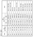
- FIG. 13 shows an example in which data indicating the insertion rate of Pad Code is added to the header.
- the data indicating the insertion rate of the Pad Code calculated by the insertion rate calculation unit 75 can be added to the Reserved area in the header, for example, as shown in FIG.
- the header generation unit 72 generates, for example, a header in which data indicating the insertion rate of the Pad Code is added to the Reserved area.
- the receiving unit 31 can receive the packet including the data indicating the insertion rate of the Pad Code in the header via the lane.
- the frame data output unit 141 and the system control unit 143 can know the insertion rate of the Pad Code.
- FIG. 14 shows a second example of an improvement example of the transmission unit 22 in the transmission system 1 according to the embodiment.
- the data indicating the insertion rate of the Pad Code calculated by the insertion rate calculation unit 75 may be stored in the register 53 on the transmitting side, for example, as shown in FIG.
- the register 53 can output data indicating the insertion rate of the Pad Code to the receiving side on a route different from the lane which is the transmission route of the packet.
- the route different from the lane may be, for example, the control line 13 shown in FIGS. 1 and 2.
- data indicating the insertion rate of the Pad Code may be received by a route different from the packet transmission route and stored in the register 142 on the receiving side.
- the frame data output unit 141 and the system control unit 143 can know the insertion rate of the Pad Code.
- the data indicating the insertion rate of the Pad Code may be stored in other than the register 142.
- the frame data output unit 141 or the system control unit 143 may store data indicating the insertion rate.
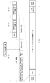
- FIG. 15 shows a third example of an improvement example of the transmission unit 22 in the transmission system 1 according to the embodiment.
- the data indicating the insertion rate of the Pad Code calculated by the insertion rate calculation unit 75 can be added to the embedded data area, for example, as shown in FIG.
- FIG. 15 shows an example in which the front dummy region A3 has the embedded data region
- the embedded data region may be inserted in the rear dummy region A4.
- the packet generation unit 64 generates, for example, a packet in which data indicating the insertion rate of the Pad Code is added to the area of the Embedded Data.
- the receiving unit 31 can receive the packet including the data indicating the insertion rate of the Pad Code in the dummy area via the lane.
- the frame data output unit 141 and the system control unit 143 can know the insertion rate of the Pad Code.
- the present technology may have the following configuration. According to the present technology having the following configuration, since it is configured so that the insertion rate of the padding code can be known, it is possible to perform optimum data processing.
- a transmitter that includes pixel data for one line constituting an image of one frame in a payload and can output a plurality of packets with a header added to the payload to a transmission line. Insertion of padding code inserted in the payload to fill the difference between the transmission rate of the pixel data input to the transmission unit and the transmission rate of the pixel data output from the transmission unit to the transmission line.
- (2) A header generation unit that can add data indicating the insertion rate of the padding code calculated by the insertion rate calculation unit to the header. The transmitter according to (1) above.
- (3) A register that can store data indicating the insertion rate of the padding code calculated by the insertion rate calculation unit, The transmitter according to (1) above.
- the register can output data indicating the insertion rate of the padding code to a receiving device capable of receiving the packet via the transmission path by a route different from the transmission path of the packet according to the above (3).
- Transmitter (5) A packet generation unit capable of generating a packet including a dummy area in the payload instead of the pixel data, and adding data indicating the insertion rate of the padding code to the dummy area.
- the transmitter according to (1) above.
- the padding code is used when the transmission rate of the pixel data output from the transmission unit to the transmission line is larger than the transmission rate of the pixel data input to the transmission unit and satisfies a predetermined condition.
- the transmitter according to any one of (1) to (5) above, which is inserted into the payload.
- the payload includes pixel data for one line constituting one frame of an image, and a receiver having a header added to the payload can be received from a transmitter of a transmitter via a transmission line. Insertion of padding code inserted in the payload to fill the difference between the transmission rate of the pixel data input to the transmission unit and the transmission rate of the pixel data output from the transmission unit to the transmission line.
- a receiving device capable of receiving rate data from the transmitting device.
- the receiving device according to (7) above, wherein the receiving unit can receive a packet including data of the insertion rate of the padding code via the transmission line.
- data indicating the insertion rate of the padding code can be received by a route different from the transmission route of the packet.
- the transmitter is A transmitter that includes pixel data for one line constituting an image of one frame in a payload and can output a plurality of packets with a header added to the payload to a transmission line. Insertion of a padding code inserted in the payload to fill the difference between the transmission rate of the pixel data input to the transmission unit and the transmission rate of the pixel data output from the transmission unit to the transmission line.
- a transmission system equipped with an insertion rate calculation unit that can calculate the rate.
- the receiving device is A receiving unit capable of receiving the plurality of packets from the transmitting unit of the transmitting device via the transmission line is provided. The transmission system according to (10) above, wherein the data of the insertion rate of the padding code can be received from the transmission device.
Landscapes
- Engineering & Computer Science (AREA)
- Signal Processing (AREA)
- Multimedia (AREA)
- Computer Networks & Wireless Communication (AREA)
- Computer Security & Cryptography (AREA)
- Physics & Mathematics (AREA)
- Computer Hardware Design (AREA)
- General Physics & Mathematics (AREA)
- Theoretical Computer Science (AREA)
- Data Exchanges In Wide-Area Networks (AREA)
- Communication Control (AREA)
Priority Applications (4)
| Application Number | Priority Date | Filing Date | Title |
|---|---|---|---|
| EP20891330.1A EP4064681A4 (en) | 2019-11-20 | 2020-11-12 | TRANSMITTING DEVICE, RECEIVING DEVICE AND TRANSMITTING SYSTEM |
| CN202080075787.1A CN114600467B (zh) | 2019-11-20 | 2020-11-12 | 发送装置、接收装置和传输系统 |
| US17/776,750 US11930296B2 (en) | 2019-11-20 | 2020-11-12 | Transmission device, reception device, and transmission system with padding code insertion |
| JP2021558335A JP7692361B2 (ja) | 2019-11-20 | 2020-11-12 | 送信装置、受信装置、および伝送システム |
Applications Claiming Priority (2)
| Application Number | Priority Date | Filing Date | Title |
|---|---|---|---|
| JP2019209580 | 2019-11-20 | ||
| JP2019-209580 | 2019-11-20 |
Publications (1)
| Publication Number | Publication Date |
|---|---|
| WO2021100602A1 true WO2021100602A1 (ja) | 2021-05-27 |
Family
ID=75981264
Family Applications (1)
| Application Number | Title | Priority Date | Filing Date |
|---|---|---|---|
| PCT/JP2020/042254 Ceased WO2021100602A1 (ja) | 2019-11-20 | 2020-11-12 | 送信装置、受信装置、および伝送システム |
Country Status (5)
| Country | Link |
|---|---|
| US (1) | US11930296B2 (https=) |
| EP (1) | EP4064681A4 (https=) |
| JP (1) | JP7692361B2 (https=) |
| CN (1) | CN114600467B (https=) |
| WO (1) | WO2021100602A1 (https=) |
Cited By (1)
| Publication number | Priority date | Publication date | Assignee | Title |
|---|---|---|---|---|
| US20220408055A1 (en) * | 2019-11-20 | 2022-12-22 | Sony Semiconductor Solutions Corporation | Transmission device, reception device, and transmission system |
Families Citing this family (1)
| Publication number | Priority date | Publication date | Assignee | Title |
|---|---|---|---|---|
| KR20240083612A (ko) * | 2022-12-05 | 2024-06-12 | 삼성전자주식회사 | 디스플레이 드라이버, 시스템 온 칩 및 이들을 포함하는 디스플레이 시스템 |
Citations (4)
| Publication number | Priority date | Publication date | Assignee | Title |
|---|---|---|---|---|
| JP2010176519A (ja) * | 2009-01-30 | 2010-08-12 | Nikon Corp | 位相調整装置およびカメラ |
| JP2011082934A (ja) * | 2009-10-09 | 2011-04-21 | Cloud Scope Technologies Inc | ストリームデータ送信装置、方法、及びプログラム |
| JP2012120158A (ja) | 2010-11-12 | 2012-06-21 | Sony Corp | 画像出力装置、画像出力方法、画像処理装置、画像処理方法、プログラム、データ構造、および撮像装置 |
| JP2019209580A (ja) | 2018-06-04 | 2019-12-12 | 大倉工業株式会社 | フレキソ印刷機、及び該印刷機を用いた印刷フィルムの製造方法、並びに印刷フィルム |
Family Cites Families (8)
| Publication number | Priority date | Publication date | Assignee | Title |
|---|---|---|---|---|
| JP3879836B2 (ja) * | 2002-03-28 | 2007-02-14 | 日本電気株式会社 | 多重変換装置、逆多重変換装置および多重伝送システム |
| US20060061517A1 (en) * | 2004-09-23 | 2006-03-23 | Jolly Paul A | Delivering pixels received at a lower data transfer rate over an interface that operates at a higher data transfer rate |
| JP5360218B2 (ja) * | 2009-08-25 | 2013-12-04 | 富士通株式会社 | 送信機、符号化装置、受信機、及び、復号化装置 |
| KR101922559B1 (ko) * | 2011-10-13 | 2018-12-05 | 삼성전자주식회사 | 통신 시스템에서 순방향 에러 정정 패킷을 송수신하는 방법 및 장치 |
| DE102015209196A1 (de) * | 2014-09-08 | 2016-03-10 | Robert Bosch Gmbh | Verfahren zur seriellen Übertragung eines Rahmens über ein Bussystem von einem Sender zu mindestens einem Empfänger und Teilnehmern eines Bussystems |
| EP3637715B1 (en) * | 2017-06-09 | 2023-07-12 | Sony Semiconductor Solutions Corporation | Transmission device, reception device, control method, program, and transmission/reception system |
| KR102195376B1 (ko) * | 2019-09-20 | 2020-12-28 | 삼성전자주식회사 | 송신 장치, 수신 장치 및 그 제어방법 |
| CN114600467B (zh) * | 2019-11-20 | 2024-12-20 | 索尼半导体解决方案公司 | 发送装置、接收装置和传输系统 |
-
2020
- 2020-11-12 CN CN202080075787.1A patent/CN114600467B/zh active Active
- 2020-11-12 US US17/776,750 patent/US11930296B2/en active Active
- 2020-11-12 WO PCT/JP2020/042254 patent/WO2021100602A1/ja not_active Ceased
- 2020-11-12 EP EP20891330.1A patent/EP4064681A4/en active Pending
- 2020-11-12 JP JP2021558335A patent/JP7692361B2/ja active Active
Patent Citations (4)
| Publication number | Priority date | Publication date | Assignee | Title |
|---|---|---|---|---|
| JP2010176519A (ja) * | 2009-01-30 | 2010-08-12 | Nikon Corp | 位相調整装置およびカメラ |
| JP2011082934A (ja) * | 2009-10-09 | 2011-04-21 | Cloud Scope Technologies Inc | ストリームデータ送信装置、方法、及びプログラム |
| JP2012120158A (ja) | 2010-11-12 | 2012-06-21 | Sony Corp | 画像出力装置、画像出力方法、画像処理装置、画像処理方法、プログラム、データ構造、および撮像装置 |
| JP2019209580A (ja) | 2018-06-04 | 2019-12-12 | 大倉工業株式会社 | フレキソ印刷機、及び該印刷機を用いた印刷フィルムの製造方法、並びに印刷フィルム |
Non-Patent Citations (1)
| Title |
|---|
| See also references of EP4064681A4 |
Cited By (2)
| Publication number | Priority date | Publication date | Assignee | Title |
|---|---|---|---|---|
| US20220408055A1 (en) * | 2019-11-20 | 2022-12-22 | Sony Semiconductor Solutions Corporation | Transmission device, reception device, and transmission system |
| US11930296B2 (en) * | 2019-11-20 | 2024-03-12 | Sony Semiconductor Solutions Corporation | Transmission device, reception device, and transmission system with padding code insertion |
Also Published As
| Publication number | Publication date |
|---|---|
| CN114600467A (zh) | 2022-06-07 |
| CN114600467B (zh) | 2024-12-20 |
| JPWO2021100602A1 (https=) | 2021-05-27 |
| EP4064681A1 (en) | 2022-09-28 |
| US11930296B2 (en) | 2024-03-12 |
| US20220408055A1 (en) | 2022-12-22 |
| EP4064681A4 (en) | 2023-01-11 |
| JP7692361B2 (ja) | 2025-06-13 |
Similar Documents
| Publication | Publication Date | Title |
|---|---|---|
| JP6349259B2 (ja) | イメージセンサおよびそのデータ伝送方法、情報処理装置および情報処理方法、電子機器、並びにプログラム | |
| US8970750B2 (en) | Image outputting apparatus, image outputting method, image processing apparatus, image processing method, program, data structure and imaging apparatus | |
| JP7547217B2 (ja) | 送信装置、送信方法、受信装置、受信方法、および送受信装置 | |
| KR20100014213A (ko) | 촬상 장치, 촬상 회로 및 화상 처리 회로 | |
| WO2016000371A1 (zh) | 多通道同步方法、同步装置及系统和计算机存储介质 | |
| JP2017011470A (ja) | シリアル通信装置及びシリアル通信方法 | |
| WO2021100602A1 (ja) | 送信装置、受信装置、および伝送システム | |
| JP7558938B2 (ja) | 送信装置、送信方法、受信装置、受信方法、および送受信装置 | |
| JP7550785B2 (ja) | 送信装置、および伝送システム | |
| CN107072515A (zh) | 图像数据传输系统 | |
| JP7611823B2 (ja) | 送信装置および通信システム | |
| JPH1013385A (ja) | パケットデータ誤り訂正方法及び装置並びにパケット受信装置 | |
| KR20250005328A (ko) | 송신 장치, 송신 방법, 수신 장치, 수신 방법, 프로그램 및 송신 시스템 | |
| US20070195822A1 (en) | Method and system for locating packet boundaries | |
| JP2016111401A (ja) | データ送信装置、データ受信装置、およびデータ通信システム | |
| JP2020096281A (ja) | 撮像装置、データ処理装置およびデータ処理方法 |
Legal Events
| Date | Code | Title | Description |
|---|---|---|---|
| 121 | Ep: the epo has been informed by wipo that ep was designated in this application |
Ref document number: 20891330 Country of ref document: EP Kind code of ref document: A1 |
|
| ENP | Entry into the national phase |
Ref document number: 2021558335 Country of ref document: JP Kind code of ref document: A |
|
| NENP | Non-entry into the national phase |
Ref country code: DE |
|
| ENP | Entry into the national phase |
Ref document number: 2020891330 Country of ref document: EP Effective date: 20220620 |