WO2021100533A1 - 認可サーバー、システム、システムの方法、および認可サーバーのプログラム - Google Patents
認可サーバー、システム、システムの方法、および認可サーバーのプログラム Download PDFInfo
- Publication number
- WO2021100533A1 WO2021100533A1 PCT/JP2020/041802 JP2020041802W WO2021100533A1 WO 2021100533 A1 WO2021100533 A1 WO 2021100533A1 JP 2020041802 W JP2020041802 W JP 2020041802W WO 2021100533 A1 WO2021100533 A1 WO 2021100533A1
- Authority
- WO
- WIPO (PCT)
- Prior art keywords
- authorization
- client
- request
- confirmation
- access token
- Prior art date
- Legal status (The legal status is an assumption and is not a legal conclusion. Google has not performed a legal analysis and makes no representation as to the accuracy of the status listed.)
- Ceased
Links
Images









Classifications
-
- H—ELECTRICITY
- H04—ELECTRIC COMMUNICATION TECHNIQUE
- H04L—TRANSMISSION OF DIGITAL INFORMATION, e.g. TELEGRAPHIC COMMUNICATION
- H04L63/00—Network architectures or network communication protocols for network security
- H04L63/08—Network architectures or network communication protocols for network security for authentication of entities
- H04L63/0807—Network architectures or network communication protocols for network security for authentication of entities using tickets, e.g. Kerberos
-
- G—PHYSICS
- G06—COMPUTING OR CALCULATING; COUNTING
- G06F—ELECTRIC DIGITAL DATA PROCESSING
- G06F21/00—Security arrangements for protecting computers, components thereof, programs or data against unauthorised activity
- G06F21/30—Authentication, i.e. establishing the identity or authorisation of security principals
- G06F21/31—User authentication
- G06F21/34—User authentication involving the use of external additional devices, e.g. dongles or smart cards
- G06F21/35—User authentication involving the use of external additional devices, e.g. dongles or smart cards communicating wirelessly
-
- G—PHYSICS
- G06—COMPUTING OR CALCULATING; COUNTING
- G06F—ELECTRIC DIGITAL DATA PROCESSING
- G06F21/00—Security arrangements for protecting computers, components thereof, programs or data against unauthorised activity
- G06F21/60—Protecting data
- G06F21/62—Protecting access to data via a platform, e.g. using keys or access control rules
-
- H—ELECTRICITY
- H04—ELECTRIC COMMUNICATION TECHNIQUE
- H04L—TRANSMISSION OF DIGITAL INFORMATION, e.g. TELEGRAPHIC COMMUNICATION
- H04L63/00—Network architectures or network communication protocols for network security
- H04L63/10—Network architectures or network communication protocols for network security for controlling access to devices or network resources
- H04L63/102—Entity profiles
-
- H—ELECTRICITY
- H04—ELECTRIC COMMUNICATION TECHNIQUE
- H04L—TRANSMISSION OF DIGITAL INFORMATION, e.g. TELEGRAPHIC COMMUNICATION
- H04L63/00—Network architectures or network communication protocols for network security
- H04L63/10—Network architectures or network communication protocols for network security for controlling access to devices or network resources
- H04L63/108—Network architectures or network communication protocols for network security for controlling access to devices or network resources when the policy decisions are valid for a limited amount of time
Definitions
- the present invention relates to an authorization server, a system, a system method, and an authorization server program that issues an access token in response to the delegation of authority to access a resource.
- Patent Document 1 discloses that when setting the system linkage, the user operates both the client and the authorization server with a web browser and delegates the user's authority to the client by performing the authorization operation.
- the client can access the user's resources using the delegated user's authority, and system linkage is realized.
- the user In order to delegate the user's authority to the client in OAuth 2.0, the user needs to access the client with a web browser.
- the flow of delegation of authority was started by the user performing an operation for delegating authority to the client.
- the flow of delegation of authority is started, and the user is physically and / or systematically separated.
- a new form of performing the authorization operation is conceivable.
- an object of the present invention is to provide a mechanism that allows a user to perform a re-authorization operation in a form in which a client's authorization request and a user's authorization operation are independent.
- the authorization server is a resource server that provides a user's resource, a client that accesses the resource, and an authorization server that issues an access token indicating that the client is permitted to access the resource.
- the authorization server in the system composed of the user terminal, the receiving means for receiving the authorization start request from the client, and the authorization confirmation request according to the receipt of the authorization start request by the receiving means.
- the authorization confirmation request is sent to the specified user terminal and the specific means for identifying the user terminal to which the token is sent, the result of the authorization confirmation is received as a response, and the authorization confirmation is performed until the re-authorization is possible.
- the authorization means for temporarily storing the result and the issuance of the access token according to the result of the authorization confirmation temporarily stored according to the time when the re-authorization is possible are controlled, and the access is performed.
- a token is issued, it is characterized by having an issuing means for transmitting the access token to the client who has transmitted the authorization start request.
- FIG. 1 is a diagram showing a configuration of an information processing device according to an embodiment for carrying out the present invention.
- the information processing device includes a CPU 102, a memory 103, a storage device 104, a video interface 105, an Output / Output (hereinafter abbreviated as I / O) interface 106, and a communication interface 107. Further, the components in the information processing apparatus are connected to each other via the system bus 101.
- the CPU 102 is a central processing unit that controls each component via the system bus 101, and performs data calculation and processing.
- the memory 103 is a device for storing data and programs, and is composed of a RAM (Random Access Memory) and a ROM (Read Only Memory).
- the storage device 104 writes / reads the stored data.
- the storage device 104 includes a hard disk drive (HDD) 111, a DVD-ROM drive 112 used as a non-volatile data source, and a solid state drive (SSD) 113 using a semiconductor memory.
- HDD hard disk drive
- DVD-ROM drive 112 used as a non-volatile data source
- SSD solid state drive
- a magnetic tape drive, a floppy (registered trademark) disk drive (FDD), a CD-ROM drive, a CD / DVD-RAM drive, a USB flash drive, and the like are also used.
- FDD floppy (registered trademark) disk drive
- CD-ROM drive CD-ROM drive
- CD / DVD-RAM compact flash drive
- USB flash drive USB flash drive
- the program according to this embodiment is read from the storage device 104, stored in the memory 103, and then executed by the CPU 102.
- the program is read from the storage device 104 in the present embodiment, it may be read from a ROM (not shown) or read from the outside via the communication interface 107.
- the video interface 105 controls the display output to the display device 114.
- Some display devices 114 use a method such as a CRT or a liquid crystal.
- An input device such as a keyboard 115 or a pointing device 116 is connected to the I / O interface 106.
- the operator issues an operation command or the like to the information processing apparatus by operating the keyboard 115.
- the pointing device 116 moves the cursor on the display device 114 to select or operate a menu or an object.
- some display devices 114 can input operations using a touch panel or the like. In this case, the display device 114 serves both as an output device and an input device.
- the communication interface 107 communicates with an external device through the computer network 117.
- the connection destination network includes a public line such as LAN, WAN, and the Internet, and may be wired or wireless.
- the communication interface 107 also communicates with other devices such as the local printer 118.
- FIG. 2 is a network configuration diagram of the authority transfer system according to this embodiment. It is assumed that the server, the client, and the user terminal shown in FIG. 2 all have the configuration of the device shown in FIG. However, the configuration is not limited to that shown in FIG. 1, and may be a rack-mounted system having other functions or not limited to a single computer. Further, in all the explanations described later, unless otherwise specified, the main body of execution of the server or the client is the CPU 102, and the main body of the software is the program stored in the storage device 104.
- the authorization server 201, the resource server 202, the client 203, and the user terminal 204 are connected to the computer network 200.
- the form of the user terminal 204 includes, for example, a portable computer such as a smartphone or a tablet terminal, a client personal computer, and the like.
- the computer network 200 includes a LAN, a WAN, the Internet, and the like, and may be wired or wireless.
- the user terminal 204 communicates with the authorization server 201 through the computer network 200, and the client 203 communicates with the authorization server 201 and the resource server 202 through the computer network 200.
- the user terminal 204 displays the data acquired by the Web browser or the dedicated client application on the display device 114 of the client terminal.
- FIG. 3 is a functional block diagram of the authority transfer system according to the present embodiment.
- 3A shows the client 203
- FIG. 3B shows the authorization server 201
- FIG. 3C shows the resource server 202
- FIG. 3D shows the functional blocks of the user terminal 204.
- the client 203 has an authorization start request issuing unit 331, an access token requesting unit 333, an access token management unit 334, and a resource access unit 332.
- the authorization server 201 has an authorization request management unit 311, an authorization confirmation request transmission destination resolution unit 312, an authorization confirmation unit 313, and an access token issuing unit 314.
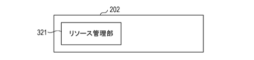
- the resource server 202 has a resource management unit 321.
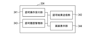
- the user terminal 204 has an authorization operation reception unit 341, an authorization result transmission unit 342, an authorization history management unit 343, and a screen display unit 344.
- the authorization request management unit 311 of the authorization server 201 processes the authorization start request in accordance with the request of the authorization start request issuing unit 331 of the client 203.
- the authorization start request includes resource information of the resource to be accessed by the client 203, the type of processing performed on the resource, client information, and the like.
- the authorization confirmation request transmission destination resolution unit 312 determines the user terminal to be the transmission destination of the authorization confirmation request by using the resource information, the processing type, the client information, etc. included in the authorization start request.
- the authorization confirmation unit 313 makes an authorization confirmation request to the user terminal 204 determined by the authorization confirmation request transmission destination resolution unit 312.
- the client 203 can acquire the access token from the authorization server 201, and can access the resource server by using the access token.
- the client 203 must be registered with the authorization server 201 before starting the protocol flow of the first embodiment.
- the authorization server 201 provides an HTML registration form (not shown) with a dialogue with the client 203 registrant.
- direct communication between the client 203 and the authorization server 201 is not essential.
- the client 203 can be registered with the authorization server 201 by using an assertion issued by the client 203 itself or a third party, or by discovering the client 203 using the secure channel of the authorization server 201.
- the registrant of the client 203 specifies the client type (“Confidential” defined in OAuth2.0), the application name, the service name, the logo image, and the usage rules.
- the authorization server 201 issues a client identifier and a client secret to the client 203.
- the client 203 stores the issued client identifier and the client secret in the authorization start request issuing unit 331.
- the authorization server 201 registers the information received from the client 203 in the client registration table (Table 1) in the authorization confirmation request transmission destination resolution unit 312.
- the user terminal 204 must be registered in the authorization server 201 before starting the protocol flow of the first embodiment.
- the authorization server 201 provides an HTML registration form (not shown) accompanied by a dialogue with the user terminal 204 registrant.
- direct communication between the user terminal 204 and the authorization server 201 is not essential.
- the user terminal 204 can be registered by using the assertion issued by the user terminal 204 or by the authorization server 201 discovering the user terminal 204 using a secure channel. Multiple user terminals can be registered.
- the authorization server 201 issues a terminal ID and a terminal secret to the user terminal 204, respectively.
- the client 203 stores the issued terminal ID and terminal Secret in the authorization operation reception unit 341.
- the registrant of the user terminal 204 specifies the following information.
- User terminal information communication endpoint for notifying an authorization confirmation request described later
- service name service name
- application name both specified when registering client 203
- user identifier user name
- the registered contents are registered in the user terminal registration table (Table 2) in the authorization confirmation request transmission destination resolution unit 312 of the authorization server 201 shown in FIG. 3B.
- the information of the user terminal 204 includes the user terminal information "192.168.0.1”, the terminal ID “Device_1”, the terminal Secret “wwwwww”, the client identifier "Client_1", the application name “App_1”, and the service.
- the name is "Servv_1” and the user identifier is "user_A”.
- user terminal information "192.168.0.2”, terminal ID “Device_2”, terminal Secret “zzzzzzzz”, client identifier "Client_1”, application name "App_1”, service The name "Servv_1” and the user identifier "user_B" are registered.
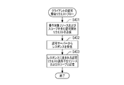
- FIG. 4A is a flow in which the client 203 makes an authorization start request to the authorization server 201. This flow is started when the client 203 needs an access token prior to accessing the resource on the resource server 202.
- the authorization start request issuing unit 331 transmits an authorization start request including a client identifier, a resource identifier to be operated, a scope, and hint information for identifying a target user to the authorization server 201.
- the scope indicates the access range of the resource. For example, "get-data" when you want to acquire the data that is the resource, and "get-all" when you want to perform other access such as editing other than acquisition. Will be specified.
- the hint information for identifying the target user indicates the user identifier. Further, the hint information may be any one of an ID token issued to a past user, a user's e-mail address, and a user identifier.
- step S402 the authorization start request issuing unit 331 receives the response from the authorization server 201.
- This response includes an authorization request identifier issued by the authorization server 201.
- step S403 the authorization start request issuing unit 331 stores the authorization request identifier included in the response received in step S402 together with the operation target resource and scope of step S401, and ends the flow.
- Table 3 is an example of the authorization request management table stored in the client 203.
- the authorization start request made with the scope “get-data” for the resource indicated by the resource identifier “/ datarake / data0010 / data” is stored in association with the authorization request identifier “aut_req_id_12345”. Further, for the authorization request identifier "aut_req_id_98765", it indicates that the access token indicated by "actk111122233" has been acquired.
- the resource indicated by the resource identifier here may indicate one file on the file system or may indicate a specific record on the database. You may also show a set of them.
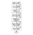
- FIG. 4B is a reception flow of an authorization start request on the authorization server 201. This flow is started when the authorization server 201 receives an authorization start request from the client 203.
- the authorization request management unit 311 receives an authorization start request from the client 203.
- the authorization start request includes the client identifier of the client 203, the resource identifier operated by the client 203, the scope requested by the client 203, and the hint information requested by the client 203.
- step S412 the authorization request management unit 311 generates an authorization request identifier corresponding to the authorization start request received in step S411.
- step S413 the authorization request management unit 311 stores the authorization request information in association with the authorization request identifier generated in step S412.
- the authorization request information includes the client identifier received in step S411, the resource identifier to be operated, the scope, and hint information.
- Table 4 is an example of the authorization confirmation status management table stored in the authorization request management unit 311.
- the authorization start request made by the client indicated by the client identifier “Client_1” with respect to the resource indicated by the resource identifier “/ datalake / data0010 / data” in the scope “get-data” is the authorization request identifier “. It is stored in association with "out_req_id_12345”. Further, the authorization request identifier "aut_req_id_12345” is associated with the user identifier "user_A" as hint information, which means that the resource owner of the resource "/ dataake / iot0010 / data” is the user identifier "user_A". Shown.
- step S416 the authorization request management unit 311 returns the authorization request identifier generated in step S414 to the client 203 as a response in step S411, and ends the flow.
- FIG. 4C is a flow for making an authorization confirmation request on the authorization server 201. This flow is started in response to storing the authorization request information in step S413. In step S421, the authorization confirmation unit 313 acquires the client identifier associated with the authorization request identifier stored in step S413.
- the authorization confirmation unit 313 identifies the user terminal that makes the authorization confirmation request from the client identifier and hint information acquired in step S421. For example, the authorization confirmation unit 313 identifies the user terminal 204 from the user terminal registration table in Table 2 in the authorization confirmation request transmission destination resolution unit 312 as the user terminal associated with the client identifier “Client_1” and the hint information “user_A”. Further, it can be seen that the communication endpoint for notifying the authorization confirmation request is "192.168.0.1".
- step S423 the authorization confirmation unit 313 acquires the client identifier and the scope associated with the authorization request identifier stored in step S413. If the authorization request identifier stored in step S413 is "aut_req_id_12345", the associated client identifier and scope are "Client_1" and “get-data”.
- the authorization confirmation unit 313 transmits an authorization confirmation request including the client identifier and the scope acquired in step S423 to the user terminal 204 specified in step S422 in step S424.
- the method of transmitting the authorization confirmation request may be a communication method in which the endpoint of the user terminal 204 is specified, a method using PUSH notification such as MQTT, or another method, but in this embodiment, the authorization end Direct communication with specified points.
- the screen display unit 344 of the user terminal 204 displays an authorization confirmation screen as shown in FIG. 9B described later, and requests the user of the terminal for authorization.
- step S425 the authorization confirmation unit 313 receives the authorization result from the user terminal 204 as a response to the authorization confirmation request transmitted in step S424.
- step S426 the authorization confirmation unit 313 stores the authorization result received in step S425 in association with the authorization request identifier stored in step S415, and ends the flow.
- Table 4 “approvered” indicating that the authorization has been granted for the authorization request identifier “out_req_id_98765” is stored.
- the above is the flow from the request for delegation of authority from the client to the authorization operation by the user.
- OAuth 2.0 The difference from OAuth 2.0 is that the client autonomously requests authorization without the user's instruction, and the user who performs the authorization operation has no intention of operating the client, and only decides whether or not to perform the authorization operation. The point is that it is only involved.
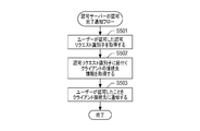
- FIG. 5A is a flow in which the authorization server 201 notifies the client 203 of the completion of authorization according to the present embodiment. This flow is started after receiving the storage of the approval result in step S426.
- the authorization confirmation unit 313 acquires the authorization request identifier stored in step S426.
- the authorization confirmation unit 313 acquires the client endpoint which is the connection destination information of the client associated with the authorization request identifier acquired in step S501.
- Table 5 is an example of a client management table that manages the correspondence between client identifiers and client endpoints.
- step S503 the authorization confirmation unit 313 notifies the client endpoint acquired in step S502 that the user has approved, and ends the flow.
- the content to be notified to the client endpoint here may be the authorization request identifier acquired in step S501, or the access token issued in response to the authorization of the user.
- the flow as shown in FIG. 5C described later is executed.
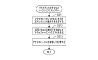
- FIG. 5B is a flow in which the client 203 makes an access token request to the authorization server 201 according to the present embodiment. This flow is started when the client 203 receives the authorization completion notification of step S503 from the authorization server 201. Alternatively, this flow may be executed by the client 203 on a regular basis.
- step S511 the access token request unit 333 determines the authorization request identifier for making the access token request.
- the authorization request identifier is selected from those for which the access token has not been acquired in the authorization request management table shown in Table 3.
- the access token request unit 333 makes an access token request to the authorization server 201 by designating the authorization request identifier determined in step S511.
- the access token management unit 334 stores the access token received as the response in step S512 and ends the flow. Table 3 shows how the access token “actk111222333” obtained for the authorization request identifier “out_req_id_98765” is stored.
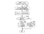
- FIG. 5C is a flow in which the authorization server 201 issues an access token according to the present embodiment. This flow is started when the authorization server 201 receives an access token request from the client 203.
- step S521 the access token issuing unit 314 acquires the authorization request identifier from the access token request received from the client 203. In step S522, the access token issuing unit 314 determines whether or not the access token can be issued. In step S523, the access token issuing unit 314 confirms whether it is determined that the access token can be issued as a result of step S522.
- step S524 If it is determined that the access token can be issued, the process proceeds to step S524. If it is determined that the access token cannot be issued, the process proceeds to step S525. In step S524, the access token issuing unit 314 issues an access token corresponding to the user identifier and scope associated with the authorization request identifier acquired in step S521. In addition, the issued access token is transmitted to the client 203 to end the flow.
- Table 6 is an example of an access token management table that manages access tokens issued by the access token issuing unit 314.
- Table 6 shows that the access token indicating that the user “user_abcde” has delegated the authority of the scope “get-data” is issued as the access token identifier “actk111222333”.
- the access token returned to the client 203 in step S524 may be only the access token identifier, or may be structured data including the user identifier and the scope in addition to the access token identifier.
- the access token issuing module 354 notifies the client 203 that the access token cannot be issued and ends the flow.
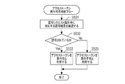
- FIG. 5D is a detailed flow of step S522 for determining whether or not to issue an access token according to the first embodiment.
- the access token issuing unit 314 refers to the authorization confirmation status management table in Table 4 and confirms the authorization result corresponding to the specified authorization request identifier.
- the access token issuing unit 314 determines whether the authorization result confirmed in step S531 indicates that it is authorized. If it indicates that it has been approved, the process proceeds to step S533, and in other cases, the process proceeds to step S534.
- step S533 the access token issuing unit 314 determines that the access token can be issued and ends the flow.
- the access token issuing unit 314 determines that the access token cannot be issued and ends the flow.
- FIG. 6 is a sequence diagram of the authority delegation system.
- the client 203 makes an authorization start request to the authorization server 201, and acquires an authorization request identifier as a response (S1).
- the authorization start request corresponds to step S401 and step S411.
- the authorization server 201 When the authorization server 201 resolves the resource owner, it makes an authorization confirmation request to the user terminal 204 associated with the resource owner (S2). On the user terminal 204, an authorization confirmation screen as shown in FIG. 9B, which will be described later, is displayed, and the user of the terminal performs the authorization operation. When the user performs the authorization operation, the user terminal 204 transmits the authorization result to the authorization server 201 (S3). S2 corresponds to step S424, and S3 corresponds to step S425.
- the client 203 After the authorization server 201 receives the authorization result, the client 203 needs to know the completion of the authorization and its contents. However, in the notification of the completion of the authorization, the client 203 confirms with the authorization server 201 and the authorization server 201 is the client. There is a method of notifying 203. In the former case, the client 203 periodically sends an access token request to the authorization server 201 (S4), and the authorization server 201 returns the authorization result as a response.
- the authorization server issues an access token to the resource server and returns it, and if the rejection is returned in S3, the result indicating that the permission is returned is returned. Since the client 203 periodically transmits the request for S4, the authorization result for S3 may not be returned yet, but in this case, the result for continuing the confirmation is returned. In the latter case, the authorization server 201 sends an authorization result notification to the client 203 (S4').
- the latter case is a method that can be performed when the client 203 has an endpoint for receiving the authorization completion notification.
- the content of the authorization result is the same as the former, and if it is permitted, an access token is issued and passed, and if it is denied, a result indicating that it is denied is returned.
- S4 corresponds to steps S512 and S521, and S4'corresponds to step S503.
- the client 203 accesses the resource server 202 by using the access token received in S4 or S4'(S5).
- a user who is physically and systematically separated from the client 203 can delegate authority to the client 203.
- the authorizing user cannot re-authorize. This is because the user terminal 204 and the client 203 are not closely linked and are sparse, so that the user who operates the user terminal 204 can also operate the client 203 and send a request for reauthorization from the user terminal 204 to the client 203. This is because that doesn't come true either.
- the user may want to correct the authorization operation after performing the authorization operation.
- a user terminal particularly a small terminal such as a smartphone
- the information display area is small and the operation panel is small
- FIG. 7 is a sequence diagram of the reauthorization process in the authority delegation system. The procedure is the same as in FIG. 6 up to the point where the user terminal 204 transmits the authorization result to the authorization server 201 (S3).
- the user can perform the reauthorization operation on the reauthorization confirmation screen as shown in FIG. 9D.
- the user terminal 204 transmits the re-authorization result to the authorization server 201 (S3').
- the content of the re-approval result is the same as the approval result.
- the endpoint of the re-authorization result reception (S3') on the authorization server 201 is separated from the authorization result reception (S3), but the implementation may be common.
- the flow of the sequence diagram is as shown in FIG. 7, but it is assumed that it may be difficult to cancel the process performed by the client 203 using the access token after the execution. Therefore, there may be a case where the authorization server 201 needs to wait for the authorization completion notification to the client 203.
- Table 7 is an example in which the authorization deadline is added to the authorization confirmation status management table stored in the authorization request management unit 311 shown in Table 4.
- the authorization result is "second promoted", which indicates that the authorization result from the user was rejected, but on the other hand, the authorization deadline is 10:32 on October 8, 2019. It shows that re-authorization is possible up to minutes 48 seconds. If a reauthorization instruction is received from the user before the authorization deadline, the authorization result will be updated. That is, the authorization result, which is the result of the user authorization operation, is buffered until the authorization deadline. The point is that processing based on the buffered authorization result is not executed. No access token is issued while buffered, even if the user authorizes it.
- the third line of Table 7 is in a state where the approval result has not been received yet, but the approval deadline has not been set. This is because it is assumed that the approval deadline is set in consideration of the waiting time for re-approval, and the re-authorization deadline is calculated and set after receiving the approval.
- the implementation may set the authorization deadline before receiving the authorization result, for example, when the authorization request is received.
- the authorization deadline interval may be determined by a preset value in the authorization request management unit 311 of the authorization server 201, or may be received from the client 203 at the time of the authorization start request.
- the authorization deadline is passed to the user terminal 204 in response to the authorization result (S3), and is also used on the authorization confirmation screen of the user terminal.
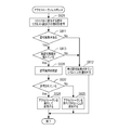
- FIG. 8 is a flowchart of the reapproval process. The flowchart of FIG. 8 is executed by the authorization confirmation unit 313 and the access token issuing unit 314 of the authorization server 201.
- FIG. 8A is a flowchart of the authorization result reception (S3) and the re-authorization result reception (S3') of FIG. 7, showing the flow from the authorization result reception (S425) portion described with reference to FIG. 4C.
- the authorization confirmation unit 313 of the authorization server 201 When the authorization confirmation unit 313 of the authorization server 201 receives the authorization result, it saves the authorization result in the information associated with the corresponding authorization request identifier (S426). Further, it is confirmed whether the authorization deadline is set in the information associated with the corresponding authorization request identifier (S801), and if the authorization deadline is not set, the period during which re-authorization is possible is acquired (S802). The period during which re-authorization is possible may be determined by a value set in advance in the authorization request management unit 311 of the authorization server 201, or may be received from the client 203 at the time of an authorization start request.
- the time limit is set in the information of the corresponding authorization request identifier (S804). For example, if the value acquired in S802 is 3 minutes and the current date and time is 10:29:48 on October 8, 2019, the deadline is 10:32:48 on October 8, 2019. That is, the authorization result is buffered until 10:32:48 on October 8, 2019. If reauthorization is not allowed, the current date and time will be set as the deadline.
- the authorization confirmation unit 313 of the authorization server 201 confirms whether the completion notification is a PUSH type method of notifying the client 203 from the authorization server 201 side shown in S4'in FIG. 7 (S805). If it is a PUSH type notification, a deadline timer event is created (S806). The deadline timer event issues an event when the deadline date and time comes, and is created for the authorization server 201 to notify the authorization completion shown in S4'in FIG. 7 when the deadline is reached. Then, the authorization server 201 returns the authorization deadline to the user terminal 204 together with the fact that the authorization result has been received (S807).
- FIG. 8B is an access token response flowchart of the authorization server 201 when the access token request (S4) of FIG. 7 is received.
- the flow from the part (S521) of acquiring the information of the authorization request identifier corresponding to the access token request described with reference to FIG. 5C is shown.
- After acquiring the information associated with the corresponding authorization request identifier it is confirmed whether the authorization result is set (S811), and if there is no authorization result, the client 203 is notified that the authorization result has not yet arrived (S812).
- the authorization completion notification process is started by the event described in S806 of FIG. 8A.
- FIG. 9 is an authorization confirmation screen performed on the user terminal 204.
- 9A is an authorization confirmation list screen
- FIG. 9B is an authorization confirmation screen
- FIG. 9C is an authorization history screen
- FIG. 9D is a reauthorization confirmation screen.
- Software for confirming authorization is installed on the user terminal 204, and when the software screen is started, the authorization confirmation list screen of FIG. 9A is displayed.
- FIG. 9A is an authorization confirmation list screen, and displays a list of authorization confirmation items received in the authorization confirmation request shown in S2 of FIG. 7.
- 901 is one of the authorization confirmation items, and displays information such as the reception date and time and resource information that shows the authorization target.
- the resource information in addition to the implementation that displays all or part of the resource information shown in Table 7 as it is, the implementation may be such that the user sets a name for the resource and displays it.
- the “>” at the right end of the authorization confirmation item 901 is a link for transitioning to the authorization confirmation screen shown in FIG. 9B.
- the tab selected in the tab for switching between the authorization confirmation list screen and the authorization history screen of FIG. 9C is highlighted.
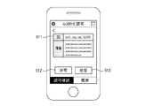
- Fig. 9B is the approval confirmation screen, and the approval is confirmed on this screen.
- ID 911 indicates an authorization request identifier, and the authorization target can be uniquely specified. Although no particular details are given regarding the information field under the ID 911, an implementation is conceivable in which supplementary information for the user to identify the authorization request is received from the client 203 or the authorization server 201 and displayed.
- the permission button 912 is a button instructing the approval confirmation to be permitted
- the denial button 913 is a button instructing the permission to be disallowed.
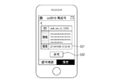
- FIG. 9C is an authorization history screen, and past authorization history can be referred to in a list.
- the authorization is confirmed in FIG. 9B, it is saved as a history in the authorization history management unit 343, and the past authorization history can be referred to.
- 921 is one of the authorization histories, and displays the date and time when the authorization was confirmed, information such as resources that shows the authorization target, and the authorization result.
- the “>” at the right end of the authorization history 921 is a link for transitioning to the reauthorization confirmation screen shown in FIG. 9D.
- the bibliographic information displayed in one of the authorization histories of 922 is the same as that of the authorization history 921, but it is grayed out and the link to the reauthorization confirmation screen is not displayed. This indicates that the re-authorization operation cannot be performed because the approval period of the target approval confirmation item has expired.
- the list of the authorization history screen there may be an implementation having a filtering function such as narrowing down to the target resource.
- FIG. 9D is a reapproval confirmation screen.
- the displayed information is the same as the approval confirmation screen of FIG. 9B, but the reapproval deadline 931 is displayed.
- Reference numeral 932 is a button for performing an authorization operation. Since the operation performed in the previous authorization confirmation was rejected, a permission button for canceling the previous operation is displayed in the reauthorization. On the contrary, when the operation performed in the previous authorization confirmation is authorization, the authorization operation button 932 displays the rejection button. It should be noted that the re-approval confirmation screen may also be implemented to display both the allow button and the deny button as shown in FIG. 9B.
- the re-authorization confirmation may be an implementation in which the user can perform the re-authorization operation as many times as long as it is within the deadline, or may be an implementation in which the number of re-authorization operations is limited. For example, it is conceivable to specify the number of times in the request from the client 203 by including the number of times in the authorization start request transmitted from the client 203. Further, the implementation may have a restriction that reapproval cannot be performed if either permission or denial is performed.
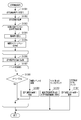
- FIG. 10A is a flowchart of the authorization history screen described in FIG. 9C. This flowchart is executed on the user terminal 204.
- the authorization confirmation list screen of FIG. 9A is displayed, and the process is started from the place where the screen switching tab 902 switches to the authorization history screen of FIG. 9C (S1001).
- the screen display unit 344 acquires the approval history from the approval history management unit 343 (S1002). Then, the remaining time is calculated by subtracting the current date and time from the expiration date and time for the authorization history whose expiration date has not passed, that is, the history in which the reauthorization operation is possible (S1003). Then, a timer event that is activated when the deadline is reached is created (S1005). Next, the screen display unit 344 displays the authorization history screen described in FIG. 9C on the display device 114 of the user terminal 204 (S1006).
- the authorization history that can be re-authorized operates the link to the re-authorization confirmation screen of FIG. 9D, and the authorization history that has passed the authorization deadline does not display the link.
- the screen operation and the deadline event created in S1005 are waited (S1007), and when the event is received, the process according to the content is executed (S1008).
- the deadline event is received, the authorization history screen is drawn and the display contents are updated (S1009).
- the screen transitions to the reauthorization confirmation screen of the selected authorization history item (S1010).
- the screen transitions to the authorization confirmation list screen (S1011).
- FIG. 10B is a sub-flow chart of the authorization history drawing in FIG. 10A.
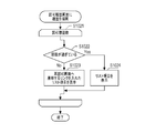
- the contents of the authorization history are confirmed for several minutes (S1021), it is determined whether or not the expiration date has passed (S1022), and if the expiration date has not passed, a list item containing a link to transition to the re-authorization screen is displayed (S1023). If the deadline has passed, the list item is displayed without inserting the link that transitions to the reapproval screen (S1024).
- the authorization confirmation can be re-operated.
- Example 2 In the first embodiment, the embodiment in which the authorization server 201 performs the waiting process for the time during which the authorization confirmation can be re-operated is shown. However, whether to allow reauthorization and whether to allow delay in response due to wait processing is considered to be related to the processing content performed by the client 203 on the resource server 202. For example, in the case where an authorization flow using a terminal is performed to settle a face-to-face product purchase, there is no need to perform waiting processing. Therefore, if the authorization server 201 performs the wait process, it may be inconvenient for the client 203.
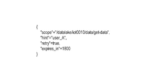
- FIG. 11 shows the information sent in the authorization start request.
- “Scope” indicates the authority range required for the processing performed by the client 203 on the resource server 202, and “hint” indicates hint information.
- “Retry” indicates whether reauthorization is possible. If it is true, it can be re-authorized, and if it is false, it cannot be re-authorized. Although the value of whether or not reapproval is possible is shown in the second embodiment, the implementation may be such that the number of times of reapproval is specified.
- “Expires_in” indicates the expiration date of approval, and in the case of 1800, it indicates that approval must be performed within 1800 seconds.
- FIG. 11 illustrates the above four items, the present invention is not limited to these four items. For example, in the case of issuing the authorization completion notification in S4'in FIG. 7, it may be necessary to include the information of the client endpoint, or the implementation may include a message character string to be displayed on the user terminal or the like. ..
- Table 8 adds an area for storing instructions such as approval / disapproval of re-authorization and response deadline passed from the client 203 to the authorization confirmation status management table stored in the authorization request management unit 311 shown in Table 7.
- the client identifiers, resources, and scopes shown in Table 7 are omitted.
- the re-authorization is "true”, indicating that re-authorization is possible.
- the response deadline is "1800", and it is an instruction that it is possible to wait 1800 seconds until the authorization completion notification from the authorization server 201.
- the authorization server 201 sets the date and time obtained by adding the response deadline to the current date and time as the authorization deadline.
- it is necessary to set the authorization deadline in consideration of the polling interval from the client.
- the interval until the next polling can be specified in the response of the authorization start request S1 and the access token request S4, but an implementation that sets it a little shorter in consideration of the processing overhead is also conceivable. Even when a response is returned from the authorization server 201 to the client 203 as in S4', an implementation is conceivable in which the response is set a little shorter in consideration of the processing overhead.
- the reauthorization is "false", indicating that the request does not allow reauthorization.
- the response deadline is "300", and it is an instruction that it is possible to wait 300 seconds until the authorization completion notification from the authorization server 201. That is, this approval deadline is not the deadline for re-approval, but the deadline until the first approval. For example, in the case where an authorization flow using a terminal is performed to settle a face-to-face product purchase, there is no need to perform waiting processing, and a response is returned immediately, so the response deadline is set short.
- the authorization server 201 sets the date and time obtained by adding the response deadline to the current date and time as the authorization deadline.
- the authorization server 201 since re-authorization is not possible, when the authorization server 201 receives the authorization result from the user terminal 204 in S3 of FIG. 7, the authorization server 201 sets the date and time when the authorization result is received as the authorization deadline. During the period when re-authorization is possible, the result of authorization confirmation is buffered and access token issuance control is not performed immediately.
- the reauthorization is "false", indicating that the request does not allow reauthorization. No response deadline is specified.
- the authorization server 201 does not set the authorization deadline when receiving the authorization request, and when the authorization result is received from the user terminal 204 in S3 of FIG. 7, the date and time when the authorization result is received is set as the authorization deadline. May be good.
- the feature of the third line is that buffering for reauthorization is not performed.
- the second and third lines of Table 8 differ depending on whether or not buffering is performed, but neither of them can be re-authorized by the user.
- the fourth line of Table 8 indicates that the reapproval is "true", the deadline is not set, the reapproval is possible, and there is no deadline. It seems that such use cases are rare, but it is conceivable that the process performed by the client 203 on the resource server 202 can be re-executed as many times as necessary, and no particular deadline is set. In this case, the authorization server 201 does not set the authorization deadline when receiving the authorization request, and does not set the authorization deadline even if the authorization result is received from the user terminal 204 in S3 of FIG.
- FIG. 12 is a flowchart of receiving the approval result in the second embodiment.
- the flowchart of FIG. 12 is executed by the authorization confirmation unit 313 and the access token issuing unit 314 of the authorization server 201.
- FIG. 12 is a flowchart of the authorization result reception (S3) and the re-authorization result reception (S3') of FIG. 7, and shows the flow from the authorization result reception (S425) portion described with reference to FIG. 4C.
- the authorization confirmation unit 313 of the authorization server 201 When the authorization confirmation unit 313 of the authorization server 201 receives the authorization result, it saves the authorization result in the information associated with the corresponding authorization request identifier (S426).
- the authorization confirmation unit 313 of the authorization server 201 confirms whether the completion notification is a PUSH type method of notifying the client 203 from the authorization server 201 side shown in S4'in FIG. 7 (S1201). Then, it is confirmed whether or not the reapproval deadline is set (S1202). Although the flow for setting the reapproval deadline has been described in the first embodiment, the reapproval deadline may not be set in the second embodiment.
- the reapproval deadline is set, check whether the deadline timer event for notifying the completion of the target authorization request identifier already exists (S1203), and if it does not exist, create a deadline timer event. (S1204). If the completion notification is a PUSH type and the reapproval deadline is not set, the approval completion notification will be sent immediately.
- the access token issuing unit 314 of the authorization server 201 confirms the authorization result (S531). If it is permitted (S532), an access token is issued and returned (S524), and if it is denied, a notification to that effect is given (S525). In addition, instead of immediately notifying the approval completion, an event or queue for notifying the approval completion may be created and the approval completion notification may be performed as a separate process.
- the authorization confirmation unit 313 of the authorization server 201 refers to the value of the reauthorization column in Table 8 to confirm whether the authorization of the target authorization request identifier can be reauthorized (S1205), and receives the authorization result.
- the authorization deadline is returned to the user terminal 204 (S1206).
- the information on whether or not the reauthorization shown in the reauthorization column of Table 8 is possible may also be returned to the user terminal in S1206.
- FIG. 13 is an access token response flowchart of the authorization server 201 when the access token request (S4) of FIG. 7 in the second embodiment is received.
- the flowchart of FIG. 13 is executed by the access token issuing unit 314 of the authorization server 201.
- the flowchart of FIG. 13 shows the flow from the portion (S521) of acquiring the information of the authorization request identifier corresponding to the access token request described in FIG. 5C.
- the reapproval deadline is set when the authorization is performed once. However, in the second embodiment, the reapproval deadline is set when the authorization start request is received, so that the expiration date is exceeded without the authorization being performed. There can also be.
- the approval result is set in S811, check whether the re-approval deadline has been exceeded (S813).
- the deadline has not been exceeded, the user notifies that the approval result has not yet arrived (S812), and waits for re-authorization confirmation from the user. If the deadline has been exceeded, the approval result is confirmed as shown in FIG. 5 (S531). If it is permitted (S532), an access token is issued and returned (S524), and if it is denied, a notification to that effect is given (S525).
- the flowchart of FIG. 14 corresponds to the flow chart of the authorization history drawing executed by the screen display unit 344 on the user terminal 204 described with reference to FIG. 10B in accordance with the flow of the reauthorization process in the second embodiment.
- the steps from S1021 to S1024 are the same as those in FIG. 10, but it is determined in step S1401 whether or not the deadline is set.
- the reapproval deadline may not be set. If the expiration date is not set, the expiration date information is not passed from the authorization server 201, and the history information is also in a state where the expiration date is not set. If the deadline is not set, a list item containing a link to transition to the reapproval screen is displayed (S1023). In this case, the deadline of 931 shown in FIG. 9D is not displayed.
- Example 2 there is also information for determining whether or not reauthorization is possible in the reapproval column in Table 8. If reauthorization is not possible using the information received in S1206 as to whether reauthorization is possible, a note indicating that reauthorization is not possible is displayed on the screen of FIG. 9B, or when the button of 912 or 913 is pressed. It may be an implementation that displays a confirmation dialog box.
- Examples 1 and 2 buffering using a dedicated storage area prepared in the RAM has been described as a form of temporarily storing the authorization result, but in a form of temporarily storing the authorization result even if it is not buffering. Any storage method may be used as long as it is available. For example, a temporary storage method is conceivable in which the result of authorization confirmation is stored in a permanent storage area and then erased later.
- the present invention is also realized by executing the following processing. That is, software (program) that realizes the functions of the above-described embodiment is supplied to the system or device via a network or various storage media, and the computer (or CPU, MPU, etc.) of the system or device reads the program. This is the process to be executed.
Landscapes
- Engineering & Computer Science (AREA)
- Computer Security & Cryptography (AREA)
- Computer Hardware Design (AREA)
- General Engineering & Computer Science (AREA)
- Computer Networks & Wireless Communication (AREA)
- Computing Systems (AREA)
- Signal Processing (AREA)
- Theoretical Computer Science (AREA)
- General Physics & Mathematics (AREA)
- Software Systems (AREA)
- Physics & Mathematics (AREA)
- General Health & Medical Sciences (AREA)
- Bioethics (AREA)
- Health & Medical Sciences (AREA)
- Information Transfer Between Computers (AREA)
- Computer And Data Communications (AREA)
Abstract
認可サーバーがユーザーからの認可結果を受信した後、再認可を行える期限を設け、期限がくるまで待ち処理を行いその後アクセストークンの発行を行う。
Description
本発明は、リソースにアクセスする権限が委譲されたことに応じてアクセストークンを発行する認可サーバー、システム、システムの方法、および認可サーバーのプログラムに関する。
ウェブシステムにおいてOAuth2.0による権限委譲の仕組みが実現されている。特許文献1ではシステム連携を設定する際、ユーザーはクライアントと認可サーバーの両方をウェブブラウザで操作し、認可操作を行うことでユーザーの権限をクライアントに委譲することを開示している。クライアントは、委譲されたユーザーの権限を用いてユーザーのリソースにアクセスでき、システム連携が実現する。OAuth2.0でユーザーの権限をクライアントに委譲するためには、ユーザーがクライアントにウェブブラウザでアクセスすることが必要になる。
従来の手法では、ユーザーがクライアントに権限委譲するための操作を行うことで権限委譲のフローが開始された。しかし、IoTデバイスの普及やスマートフォンのような携帯端末の普及により、クライアントが自律的に権限委譲の要求を行うと権限委譲のフローが開始され、ユーザーが物理的および/またはシステム的に離れたところで認可操作を行う形態が新たに考えられる。
しかしながら、この形態の場合、ユーザーは一度行った認可操作を訂正したくとも、クライアントの認可要求とユーザーの認可操作が独立してしまうためユーザー側から再認可操作を行うことができなくなる懸念がある。そこで、本願発明の目的は、クライアントの認可要求とユーザーの認可操作が独立している形態において、ユーザーは再認可操作を行うことが可能な仕組みを提供することにある。
本実施形態に係る認可サーバーは、ユーザーのリソースを提供するリソースサーバー、前記リソースへアクセスするクライアント、前記クライアントが前記リソースへアクセスすることがユーザーにより許可されたことを示すアクセストークンを発行する認可サーバー、およびユーザー端末とから構成されるシステムにおける前記認可サーバーであって、前記クライアントから認可開始リクエストを受信する受信手段と、前記受信手段により認可開始リクエストが受信されたことに応じて、認可確認リクエストの送信先となるユーザー端末を特定する特定手段と、特定されたユーザー端末に対して認可確認リクエストを送信し、応答として認可確認の結果を受信し、再認可が可能な期間まで前記認可確認の結果を一時的に記憶する認可手段と、再認可が可能な期間を超えたことに応じて一時的に記憶されている前記認可確認の結果に応じたアクセストークンの発行の制御を行い、前記アクセストークンを発行した場合は前記認可開始リクエストを送信した前記クライアントへ前記アクセストークンを送信する発行手段と、を有することを特徴とする。
クライアントの認可要求とユーザーの認可操作が独立している形態において、ユーザーは再認可操作を行うことができる仕組みを提供する。
[実施例1]
以下、本発明を実施するための形態について図面を用いて説明する。図1は、本発明を実施するための一実施形態に係る情報処理装置の構成を示す図である。図1において、情報処理装置は、CPU102、メモリ103、記憶装置104、ビデオインタフェース105、Input/Output(以下I/Oと略称)インタフェース106、通信インタフェース107を備えている。また、情報処理装置内の各構成要素はシステムバス101を介して互いに接続されている。CPU102は、システムバス101を介して各構成要素を制御したり、データの計算や加工を行ったりする中央処理装置である。メモリ103は、データやプログラムを記憶する装置で、RAM(Random Access Memory)やROM(Read Only Memory)から構成される。
以下、本発明を実施するための形態について図面を用いて説明する。図1は、本発明を実施するための一実施形態に係る情報処理装置の構成を示す図である。図1において、情報処理装置は、CPU102、メモリ103、記憶装置104、ビデオインタフェース105、Input/Output(以下I/Oと略称)インタフェース106、通信インタフェース107を備えている。また、情報処理装置内の各構成要素はシステムバス101を介して互いに接続されている。CPU102は、システムバス101を介して各構成要素を制御したり、データの計算や加工を行ったりする中央処理装置である。メモリ103は、データやプログラムを記憶する装置で、RAM(Random Access Memory)やROM(Read Only Memory)から構成される。
記憶装置104は、記憶されたデータの書き込み/読み出しを行う。記憶装置104には、ハードディスクドライブ(HDD)111、不揮発性のデータソースとして利用されるDVD-ROMドライブ112、半導体メモリを用いたソリッドステートドライブ(SSD)113がある。図1には示されていないが、記憶装置104として、磁気テープドライブ、フロッピー(登録商標)ディスクドライブ(FDD)、CD-ROMドライブ、CD/DVD-RAMドライブ、USBフラッシュドライブなども使用されることがある。
本実施形態に係るプログラムは、記憶装置104から読み込まれ、メモリ103に格納した上で、CPU102によって実行される。なお、本実施形態ではプログラムを記憶装置104から読み込む構成としているが、ROM(不図示)から読み込んだり、通信インタフェース107を介して外部から読み込んだりする構成としてもよい。
ビデオインタフェース105は、ディスプレイ装置114への表示出力を制御する。ディスプレイ装置114には、CRTや液晶等の方式を用いたものがある。I/Oインタフェース106には、キーボード115やポインティングデバイス116等の入力装置が接続される。操作者は、キーボード115を操作することにより情報処理装置に対する動作指令等を行う。ポインティングデバイス116は、ディスプレイ装置114上のカーソルを移動させてメニューやオブジェクトの選択や操作等を行う。また、ディスプレイ装置114には、タッチパネル等による操作の入力を行えるものもある。この場合、ディスプレイ装置114は出力装置と入力装置を兼ねることになる。
通信インタフェース107は、コンピュータネットワーク117を通して外部機器との通信を行う。接続先のネットワークには、LANやWAN、インターネットのような公衆回線等があり、有線であっても無線であっても構わない。また、通信インタフェース107は、ローカルプリンタ118などの他デバイスとの通信も行う。
図2は、本実施形態に係る権限移譲システムのネットワーク構成図である。図2に図示されるサーバー、クライアント、ユーザー端末はいずれも、図1で示した装置の構成を備えているものとする。ただし、図1の構成に限定するものではなく、他の機能を備えている場合や、単体のコンピュータに限らないラックマウント型のシステムであっても構わない。また、後述の全ての説明において、特に断りのない限りサーバーやクライアントの実行の主体はCPU102であり、ソフトウェア上の主体は記憶装置104に保管されたプログラムである。
図2において、コンピュータネットワーク200には、認可サーバー201、リソースサーバー202、クライアント203、および、ユーザー端末204が接続されている。ユーザー端末204の形態としては、例えば、スマートフォンやタブレット端末等のような携帯可能なコンピュータや、クライアントパーソナルコンピュータ等がある。コンピュータネットワーク200には、LAN、WAN、インターネット等があり、有線であっても無線であっても構わない。
本実施形態において、ユーザー端末204は、コンピュータネットワーク200を通じて認可サーバー201と通信を行い、クライアント203はコンピュータネットワーク200を通じて認可サーバー201やリソースサーバー202と通信を行う。ユーザー端末204は、データを受信するとWebブラウザあるいは専用のクライアントアプリケーションが取得したデータをクライアント端末のディスプレイ装置114に表示する。
図3は本実施の形態に係る権限移譲システムの機能ブロック図である。図3Aはクライアント203、図3Bは認可サーバー201、図3Cはリソースサーバー202、図3Dはユーザー端末204の機能ブロックを示す。クライアント203は認可開始リクエスト発行部331、アクセストークン要求部333、アクセストークン管理部334、リソースアクセス部332を持つ。認可サーバー201は認可リクエスト管理部311、認可確認リクエスト送信先解決部312、認可確認部313、アクセストークン発行部314を持つ。リソースサーバー202はリソース管理部321を持つ。ユーザー端末204は認可操作受付部341、認可結果送信部342、認可履歴管理部343、画面表示部344を持つ。
認可サーバー201の認可リクエスト管理部311は、クライアント203の認可開始リクエスト発行部331の要求に従い、認可開始リクエストを処理する。ここで認可開始リクエストにはクライアント203がアクセスしようとするリソースのリソース情報、リソースに対して行う処理の種別、クライアント情報などが含まれる。認可確認リクエスト送信先解決部312は認可開始リクエストに含まれるリソース情報、処理種別、クライアント情報などを用いて、認可確認リクエストの送信先となるユーザー端末を決定する。認可確認部313は認可確認リクエスト送信先解決部312で決定されたユーザー端末204に対して認可確認リクエストを行う。ユーザー端末204を利用するユーザーが認可操作を行うと、クライアント203は認可サーバー201からアクセストークンを取得できるようになり、アクセストークンを使ってリソースサーバーにアクセスできるようになる。
OAuth2.0と同様、クライアント203は、実施例1のプロトコルフローを開始する以前に認可サーバー201に登録されていなければならない。クライアント203を認可サーバー201に登録させるため、認可サーバー201はクライアント203登録者との対話を伴うHTML登録フォーム(不図示)を提供する。また、本実施例のクライアント203の登録においては、クライアント203と認可サーバー201の間に直接的なやりとりは必須ではない。例えば、クライアント203自身あるいはサードパーティーが発行したアサーションの使用や、認可サーバー201のセキュアなチャネルを使用したクライアント203をディスカバリーで、クライアント203を認可サーバー201へ登録することもできる。
実施例1において認可サーバー201にクライアント203を登録する場合、クライアント203の登録者は、クライアントタイプ(OAuth2.0定義の“Confidential”)、アプリケーション名、サービス名、ロゴイメージ、利用規則を指定する。また登録の際、クライアント203に対して認可サーバー201はクライアント識別子とクライアントSecretを発行する。クライアント203は発行されたクライアント識別子とクライアントSecretを認可開始リクエスト発行部331に記憶しておく。
また、認可サーバー201は、クライアント203から受信した情報を認可確認リクエスト送信先解決部312内のクライアント登録テーブル(表1)に登録する。

さらに、ユーザー端末204は、実施例1のプロトコルフローを開始する以前に、認可サーバー201に登録されていなければならない。ユーザー端末204を認可サーバー201に登録させるため、認可サーバー201はユーザー端末204登録者との対話を伴うHTML登録フォーム(不図示)を提供する。
また、実施例1のユーザー端末204の登録において、ユーザー端末204と認可サーバー201の間に直接的なやりとりは必須ではない。例えば、ユーザー端末204が発行したアサーションを使用したり、認可サーバー201がセキュアなチャンネルを使用してユーザー端末204のディスカバリーを行ったりすることで、ユーザー端末204を登録することもできる。ユーザー端末は複数登録が可能である。
登録の際、ユーザー端末204に対して認可サーバー201は、各々端末IDと端末Secretを発行する。クライアント203は発行された端末IDと端末Secretを認可操作受付部341に記憶しておく。実施例1において、認可サーバー201にユーザー端末204を登録する場合、ユーザー端末204の登録者は以下の情報を指定する。ユーザー端末情報(後述の認可確認リクエストを通知する通信のエンドポイント)、サービス名、アプリケーション名(共にクライアント203の登録の際に指定したもの)、ユーザー識別子(ユーザー名)である。
ユーザー端末204登録の際に、登録内容は、図3Bで示される認可サーバー201の認可確認リクエスト送信先解決部312内のユーザー端末登録テーブル(表2)に登録される。
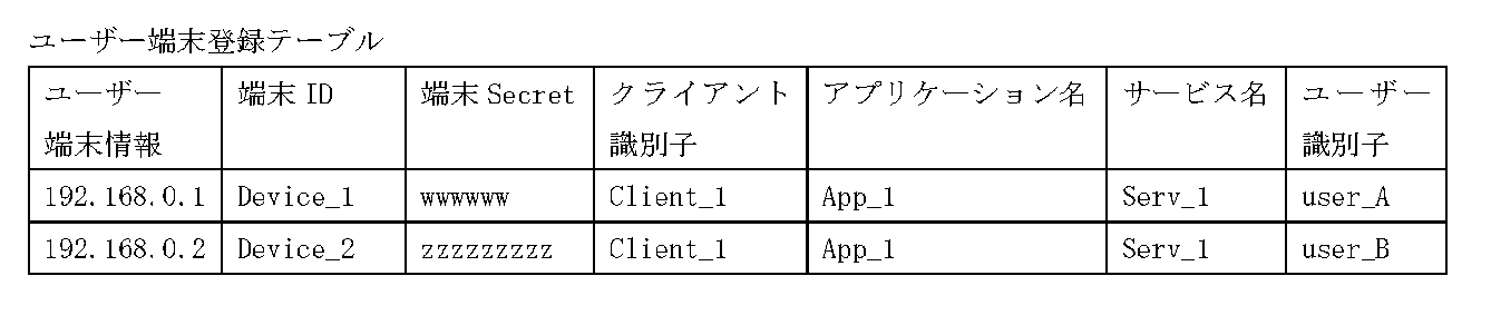
実施例1において、ユーザー端末204の情報は、ユーザー端末情報“192.168.0.1”、端末ID“Device_1”、端末Secret“wwwwww”、クライアント識別子“Client_1”、アプリケーション名“App_1”、サービス名“Serv_1”、ユーザー識別子“user_A”である。また、表2には別のユーザー端末として、ユーザー端末情報“192.168.0.2”、端末ID“Device_2”、端末Secret“zzzzzzzzz”、クライアント識別子“Client_1”、アプリケーション名“App_1”、サービス名“Serv_1”、ユーザー識別子“user_B”が登録されている。
図4Aはクライアント203が認可サーバー201に対し認可開始リクエストを行うフローである。本フローはクライアント203がリソースサーバー202上のリソースへのアクセスに先立ち、アクセストークンが必要になった際に開始される。
ステップS401で認可開始リクエスト発行部331は、クライアント識別子、操作対象のリソース識別子、スコープおよび対象となるユーザーを特定するためのヒント情報を含む認可開始リクエストを、認可サーバー201に対して送信する。ここで各用語について補足する。スコープとは、リソースのアクセス範囲を示すもので、例えば、リソースであるデータを取得したい場合は“get-data”、取得以外に編集などのそれ以外のアクセスを行いたい場合は“get-all”を指定することになる。対象となるユーザーを特定するためのヒント情報は、ユーザー識別子を示す。またヒント情報は、過去ユーザーに対して発行されたIDトークン、ユーザーのメールアドレス、ユーザー識別子のいずれかの情報であってもよい。
ステップS402で認可開始リクエスト発行部331は、認可サーバー201からレスポンスを受信する。このレスポンスには、認可サーバー201が発行した認可リクエスト識別子が含まれる。ステップS403で認可開始リクエスト発行部331は、ステップS402で受信したレスポンスに含まれる認可リクエスト識別子を、ステップS401の操作対象リソースおよびスコープとともに記憶してフローを終了する。
表3はクライアント203が記憶する認可リクエスト管理テーブルの例である。
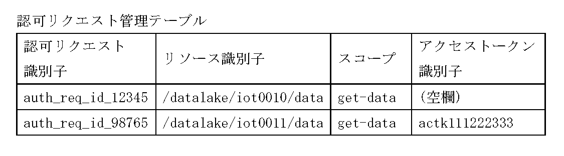
表3ではリソース識別子“/datalake/iot0010/data”で示されるリソースに対し、スコープ“get-data”で行った認可開始リクエストが、認可リクエスト識別子“auth_req_id_12345”に紐付けて記憶されている。また認可リクエスト識別子“auth_req_id_98765”に対しては、“actk111222333”で示されるアクセストークンを取得済みであることを示す。ここでリソース識別子が示すリソースは、ファイルシステム上の1つのファイルを示してもよく、データベース上の特定のレコードを示してもよい。またそれらの集合を示してもよい。
図4Bは認可サーバー201における認可開始リクエストの受信フローである。本フローは認可サーバー201がクライアント203から認可開始リクエストを受信することで開始される。
ステップS411で認可リクエスト管理部311は、クライアント203から認可開始リクエストを受け付ける。ここで認可開始リクエストには、クライアント203のクライアント識別子と、クライアント203が操作対象としているリソース識別子と、クライアント203が要求するスコープと、クライアント203が要求するヒント情報が含まれる。
ステップS412で認可リクエスト管理部311は、ステップS411で受信した認可開始リクエストに対応する認可リクエスト識別子を生成する。ステップS413で認可リクエスト管理部311は、ステップS412で生成した認可リクエスト識別子に、認可リクエストの情報を紐付けて記憶する。ここで認可リクエストの情報とは、ステップS411で受信したクライアント識別子、操作対象のリソース識別子、スコープと、ヒント情報を含む。
表4は認可リクエスト管理部311が記憶する認可確認状況管理テーブルの例である。
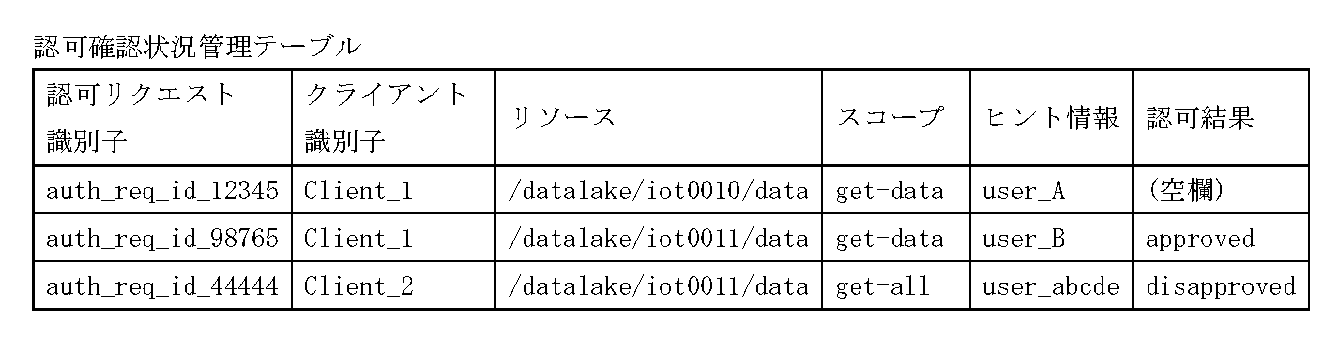
表4では、クライアント識別子“Client_1”で示されるクライアントが、リソース識別子“/datalake/iot0010/data”で示されるリソースに対し、スコープ“get-data”で行った認可開始リクエストが、認可リクエスト識別子“auth_req_id_12345”に紐付けて記憶されている。また認可リクエスト識別子“auth_req_id_12345”にはヒント情報としてユーザー識別子“user_A”が紐付けられているが、これはリソース“/datalake/iot0010/data”のリソース所有者がユーザー識別子“user_A”であることを示している。なお認可リクエスト識別子“auth_req_id_12345”の認可結果が“(空欄)”となっているのは、ユーザーがまだ認可操作を行っていないことを示している。それに対し認可リクエスト識別子“auth_req_id_98765”の認可結果は“approved”で、認可リクエスト識別子“auth_req_id_44444”の認可結果は“disapproved”である。これらはそれぞれ、ユーザーが認可を行ったことと、認可を拒否したことを示す認可確認の結果である。ステップS416で認可リクエスト管理部311は、ステップS411の応答として、ステップS414で生成した認可リクエスト識別子をクライアント203に返し、フローを終了する。
図4Cは認可サーバー201における認可確認リクエストを行うフローである。本フローはステップS413で認可リクエストの情報を記憶したことを受けて開始される。ステップS421で認可確認部313は、ステップS413で記憶した認可リクエスト識別子に紐付くクライアント識別子を取得する。
ここで、ステップS413で記憶した認可リクエスト識別子が“auth_req_id_12345”であれば、紐付くクライアント識別子は“Client_1”、ヒント情報は“user_A”である。ステップS422で認可確認部313は、ステップS421で取得したクライアント識別子とヒント情報から認可確認リクエストを行うユーザー端末を特定する。例えば、認可確認部313はクライアント識別子“Client_1”とヒント情報“user_A”に紐づくユーザー端末として、認可確認リクエスト送信先解決部312内の表2ユーザー端末登録テーブルよりユーザー端末204を特定する。また、認可確認リクエストを通知する通信のエンドポイントは“192.168.0.1”であることが分かる。
ステップS423で認可確認部313は、ステップS413で記憶した認可リクエスト識別子に紐付くクライアント識別子およびスコープを取得する。ステップS413で記憶した認可リクエスト識別子が“auth_req_id_12345”であれば、紐付くクライアント識別子およびスコープは“Client_1”および“get-data”である。
ステップS424で認可確認部313は、ステップS422で特定したユーザー端末204に対し、ステップS423で取得したクライアント識別子およびスコープを含めて認可確認リクエストを送信する。なお認可確認リクエストの送信方法は、ユーザー端末204のエンドポイントを指定した通信方法でもよいし、MQTTをはじめとするPUSH通知を用いた方法や、その他の方法でもよいが、本実施例では認可エンドポイントを指定した直接通信とする。ユーザー端末204の画面表示部344は、後述の図9Bに示すような認可確認画面を表示し、端末のユーザーに認可を求める。
ステップS425で認可確認部313は、ステップS424で送信した認可確認リクエストの応答として、ユーザー端末204から認可結果を受信する。ステップS426で認可確認部313は、ステップS425で受信した認可結果を、ステップS415で記憶した認可リクエスト識別子に紐付けて記憶してフローを終了する。表4では、認可リクエスト識別子“auth_req_id_98765”に対し認可されたことを示す“approved”が記憶されている。以上がクライアントから権限委譲要求を行いユーザーにより認可操作されるまでのフローである。OAuth2.0と異なるのは、クライアントがユーザーの指示なく自律的に認可要求を行う点と、認可操作を行うユーザーはクライアントを操作する意思はなく、あくまで認可操作を行うか否かの意思決定にのみ関わるという点である。
図5Aは本実施の形態に係る、認可サーバー201がクライアント203に認可完了通知を行うフローである。本フローはステップS426で認可結果を記憶したことを受けた後で開始される。ステップS501で認可確認部313は、ステップS426で記憶した認可リクエスト識別子を取得する。ステップS502で認可確認部313は、ステップS501で取得した認可リクエスト識別子に紐付くクライアントの接続先情報であるクライアントエンドポイントを取得する。
表5はクライアント識別子とクライアントエンドポイントの対応を管理する、クライアント管理テーブルの例である。

表5では、クライアント識別子“Client_1”のクライアントエンドポイントが、“10.0.0.1”であることを示している。ステップS503で認可確認部313は、ステップS502で取得したクライアントエンドポイントに対し、ユーザーが認可したことを通知し、フローを終了する。なおここでクライアントエンドポイントに通知する内容は、ステップS501で取得した認可リクエスト識別子でもよく、またユーザーの認可に対応して発行したアクセストークンでもよい。アクセストークンを発行する際は後述の図5Cに示されるようなフローを実行する。
図5Bは本実施の形態に係る、クライアント203が認可サーバー201にアクセストークンリクエストを行うフローである。本フローはクライアント203が認可サーバー201からステップS503の認可完了通知を受けて開始される。または本フローは、クライアント203が、定期的に実行してもよい。
ステップS511でアクセストークン要求部333は、アクセストークンリクエストを行う認可リクエスト識別子を決定する。ここで本フローが定期的に実行される場合には、認可リクエスト識別子は、表3に示される認可リクエスト管理テーブルでアクセストークン未取得のものから選ばれる。また本フローが認可サーバー201からの通知を受けて開始される場合は、認可サーバー201からの通知に含まれる認可リクエスト識別子が用いられる。ステップS512でアクセストークン要求部333は、ステップS511で決定した認可リクエスト識別子を指定して、認可サーバー201に対してアクセストークンリクエストを行う。ステップS513でアクセストークン管理部334は、ステップS512の応答として受信したアクセストークンを記憶してフローを終了する。表3では、認可リクエスト識別子“auth_req_id_98765”に対して取得できた、アクセストークン“actk111222333”を記憶している様子を示す。
図5Cは本実施の形態に係る、認可サーバー201がアクセストークンを発行するフローである。本フローは認可サーバー201がクライアント203からアクセストークンリクエストを受信したことで開始される。
ステップS521でアクセストークン発行部314は、クライアント203から受信したアクセストークンリクエストから、認可リクエスト識別子を取得する。ステップS522でアクセストークン発行部314は、アクセストークン発行可否を判断する。ステップS523でアクセストークン発行部314は、ステップS522の結果、アクセストークンを発行可能であると判断されたか確認する。
アクセストークンを発行可能と判断された場合はステップS524に遷移する。またアクセストークンを発行不可能と判断された場合はステップS525に遷移する。ステップS524でアクセストークン発行部314は、ステップS521で取得した認可リクエスト識別子に紐付けられたユーザー識別子およびスコープに対応するアクセストークンを発行する。また発行したアクセストークンをクライアント203に送信しフローを終了する。
表6はアクセストークン発行部314で発行されたアクセストークンを管理する、アクセストークン管理テーブルの例である。
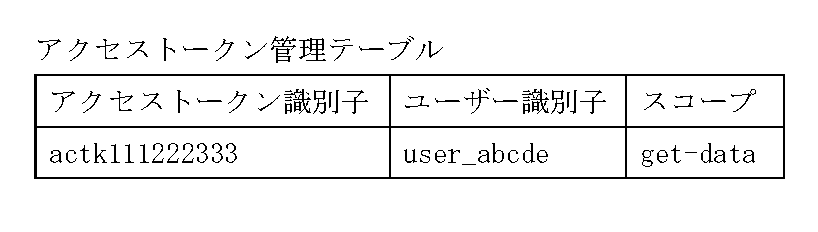
表6では、ユーザー“user_abcde”がスコープ“get-data”の権限委譲を行ったことを示すアクセストークンが、アクセストークン識別子“actk111222333”として発行されていることを示す。なお、ステップS524でクライアント203に返すアクセストークンはアクセストークン識別子だけでもよく、またアクセストークン識別子に加えユーザー識別子およびスコープを含む構造化されたデータでもよい。ステップS525でクセストークン発行モジュール354は、アクセストークンを発行できないことをクライアント203に通知してフローを終了する。
図5Dは実施例1に係るアクセストークン発行可否判断を行うステップS522の詳細フローである。ステップS531でアクセストークン発行部314は、表4の認可確認状況管理テーブルを参照し、指定された認可リクエスト識別子に対応する認可結果を確認する。ステップS532でアクセストークン発行部314は、ステップS531の確認した認可結果が、認可されていることを表しているか判断する。認可されていることを表していた場合はステップS533に遷移し、その他の場合はステップS534に遷移する。ステップS533でアクセストークン発行部314は、アクセストークンを発行可能と判断してフローを終了する。ステップS534でアクセストークン発行部314は、アクセストークンを発行不可能と判断してフローを終了する。
図6は権限委譲システムのシーケンス図である。クライアント203は認可サーバー201に対し認可開始リクエストを行い、応答として認可リクエスト識別子を取得する(S1)。認可開始リクエストはステップS401およびステップS411に対応する。
認可サーバー201はリソース所有者の解決をすると、リソース所有者に紐付けられたユーザー端末204に対し認可確認リクエストを行う(S2)。ユーザー端末204では後述の図9Bに示すような認可確認画面が表示され、端末のユーザーが認可操作を行う。ユーザーが認可操作を行うと、ユーザー端末204は認可サーバー201に認可結果を送信する(S3)。S2はステップS424に、S3はステップS425に、それぞれ対応する。
認可サーバー201が認可結果を受信した後、クライアント203が認可の完了とその内容を知る必要があるが、認可完了の通知には、クライアント203が認可サーバー201に確認する方法と認可サーバー201がクライアント203に通知する方法がある。前者の場合、クライアント203が定期的に認可サーバー201にアクセストークンリクエストを送信し(S4)、その応答として認可サーバー201が認可結果を返す。
この際、S3で許可が返されている場合、認可サーバーはリソースサーバーへのアクセストークンを発行して返し、S3で拒否が返されている場合は拒否されたことを示す結果を返す。なお、クライアント203は定期的にS4のリクエストを送信するため、未だS3の認可結果が返されていない場合があるが、この場合は引き続き確認を継続する旨の結果を返す。後者は認可サーバー201がクライアント203に認可結果通知を送信する(S4’)。
後者のケースはクライアント203が認可完了通知を受信するためのエンドポイントを持っている場合に行える方法となる。認可結果の内容は前者と同じで、許可された場合はアクセストークンを発行して渡し、拒否された場合は拒否されたことを示す結果を返す。S4はステップS512およびステップS521に、S4’はステップS503にそれぞれ対応する。クライアント203は、S4もしくはS4’で受信したアクセストークンを利用してリソースサーバー202にアクセスを行う(S5)。
このように、クライアント203とは物理的、システム的に離れたユーザーがクライアント203に権限委譲を行うことが可能となる。しかし、物理的、システム的に離れたことによって、認可を行うユーザーが再認可することができない課題が発生している。なぜなら、ユーザー端末204とクライアント203が密に連携しておらず疎であるため、ユーザー端末204を操作するユーザーはクライアント203を操作することも、ユーザー端末204からクライアント203へ再認可の要求を送ることも叶わないからである。
だが、ユーザーは認可操作を行なった後、認可操作を訂正したいと考える可能性もありうる。また、ユーザー端末、とりわけスマートフォンのような小型の端末では、情報の表示領域が少なく操作パネルも小さいため、ユーザーの認識違いによるミスや操作ミスが起こる可能性も高くなる。そのため、認可操作を再び行えるようにする必要性が出てくる。
図7は権限委譲システムにおける再認可処理のシーケンス図である。ユーザー端末204が認可サーバー201に認可結果を送信する(S3)ところまでは図6と同様である。ここで、ユーザーが認可結果を訂正したい場合、ユーザーは図9Dに示すような再認可確認画面で再認可の操作を行うことができる。ユーザーが再認可操作を行うと、ユーザー端末204は認可サーバー201に再認可結果を送信する(S3’)。再認可結果の内容は認可結果と同様である。なお、図6では、認可サーバー201における再認可結果受信(S3’)のエンドポイントを認可結果受信(S3)と分けているが、共通にする実装であってもよい。
シーケンス図のフローは図7の通りであるが、クライアント203がアクセストークンを使って行う処理は実施後の取り消しが難しい場合も想定される。従って、認可サーバー201がクライアント203への認可完了通知を待つ必要があるケースも考えられる。
表7は、表4で示した認可リクエスト管理部311が記憶する認可確認状況管理テーブルに、認可期限を追加した例である。

表7の一行目では、認可結果が“disapproved”となっており、ユーザーからの認可結果が拒否であったことを示しているが、一方、認可期限である2019年10月8日10時32分48秒までは再認可が可能であることを示している。認可期限前にユーザーから再認可の指示を受信した場合、認可結果は更新される。つまり、ユーザーの認可操作の結果である認可結果は認可期限までバッファリングされる。ポイントは、バッファリングされている認可結果に基づく処理は実行されないという点である。たとえユーザーが認可したとしても、バッファリングされている間はアクセストークンが発行されない。
表7の3行目は、未だ認可結果を受信していない状態となっているが、認可期限も設定されていない。これは認可期限が再認可待ちの時間を考慮して設定されることを想定したもので、認可を受信してから再認可期限を算出して設定するためである。なお、認可期限の設定に関して認可結果を受信する前、例えば、認可リクエストを受信した時点で認可期限を設ける実装であってもよい。また、認可期限の間隔に関しては認可サーバー201の認可リクエスト管理部311に予め設定された値によって決定する実装や、クライアント203から認可開始リクエスト時に受信する実装などがあってもよい。さらに、認可期限は認可結果(S3)の応答で、ユーザー端末204に渡され、ユーザー端末の認可確認画面でも利用される。
図8は再認可処理に関するフローチャートである。図8のフローチャートは認可サーバー201の認可確認部313、アクセストークン発行部314で実行される。図8Aは、図7の認可結果の受信(S3)および再認可結果受信(S3’)のフローチャートで、図4Cで説明した認可結果の受信(S425)部分からのフローを示している。
認可サーバー201の認可確認部313は、認可結果を受信すると該当する認可リクエスト識別子に紐付く情報に認可結果を保存する(S426)。そしてさらに、該当する認可リクエスト識別子に紐付く情報に認可期限が設定されているかを確認し(S801)、認可期限が設定されていない場合は、再認可が可能な期間を取得する(S802)。再認可が可能な期間は認可サーバー201の認可リクエスト管理部311に予め設定された値によって決定する実装や、クライアント203から認可開始リクエスト時に受信する実装などがあってもよい。そして、現在日時から再認可可能な期限となる日時を算出した上で(S803)、該当する認可リクエスト識別子の情報に期限を設定する(S804)。例えばS802で取得した値が3分であり、現在日時が2019年10月8日10時29分48秒であったとすると、期限は2019年10月8日10時32分48秒となる。つまり、認可結果は2019年10月8日10時32分48秒までバッファリングされる。なお、再認可を許容しない場合には、期限には現在日時が設定される。
次に、認可サーバー201の認可確認部313は、完了通知が図7のS4’で示す認可サーバー201側からクライアント203に通知するPUSH型の方法かどうかを確認する(S805)。そしてPUSH型の通知であれば、期限タイマーイベントを作成する(S806)。期限タイマーイベントは、期限の日時になった際にイベントを発行するもので、期限がきた時に認可サーバー201が図7のS4’で示す認可完了通知を行うために作成される。そして認可サーバー201は認可結果を受信した旨と共に、認可期限をユーザー端末204に返す(S807)。
図8Bは、図7のアクセストークンリクエスト(S4)を受信した際の認可サーバー201のアクセストークンレスポンスフローチャートである。図5Cで説明したアクセストークンリクエストに該当する認可リクエスト識別子の情報を取得する(S521)部分からのフローを示している。該当する認可リクエスト識別子に紐付く情報を取得したら、認可結果が設定されているかを確認し(S811)、認可結果がない場合は未だ認可結果がきていないことをクライアント203に通知する(S812)。
認可結果が設定されている場合は再認可期限を越えているかどうかを確認する(S813)。ここで、期限を越えていなかった場合、未だ認可結果がきていないことを通知して(S812)、ユーザーからの再認可確認を待つ。期限を越えていた場合は図5で示したように、認可結果を確認し(S531)、許可された場合(S532)はアクセストークンを発行して返し(S524)、拒否された場合はその旨を通知する(S525)。なお、図7のS4’で示した認可サーバー201からクライアント203へ認可完了通知を返す方法に関しては、図8AのS806で説明したイベントによって認可完了通知処理が開始される。
図9はユーザー端末204で行う認可確認画面である。図9Aは認可確認リスト画面、図9Bは認可確認画面、図9Cは認可履歴画面、図9Dは再認可確認画面である。ユーザー端末204上に認可確認を行うためのソフトウェアがインストールされており、ソフトウェアの画面を起動すると、図9Aの認可確認リスト画面が表示される。
図9Aは認可確認リスト画面で、図7のS2で示す認可確認リクエストで受信した認可確認項目をリスト表示する。901は認可確認項目の一つで、受信日時、リソース情報など認可対象がわかる情報を表示している。リソース情報に関しては、表7で示しめしたリソース情報をそのまま全部または一部表示する実装の他、リソースに対してユーザーが名前を設定して表示するような実装であってもよい。認可確認項目901の右端にある“>”は、図9Bで示す認可確認画面へ遷移するリンクである。902は、認可確認リスト画面と図9Cの認可履歴画面とを切替えるタブで選択されているタブがハイライトされている。
図9Bは認可確認画面で、この画面で認可確認を行う。ID911は認可リクエスト識別子を示しており、認可する対象を一意に特定することができる。なお、ID911下の情報欄に関しては特に詳細は記載しないが、ユーザーが認可リクエストを識別するための補足情報をクライアント203や認可サーバー201から受信し表示するような実装が考えられる。許可ボタン912は認可確認に対して許可することを指示し、拒否ボタン913は認可を不許可とすることを指示するボタンである。ユーザーは、許可ボタン912または拒否ボタン913を押下することで認可操作を行うと、認可結果送信部342によって、図7のS3で示した認可結果の送信が行われる。
図9Cは認可履歴画面で、過去の認可履歴をリストで参照することができる。図9Bで認可確認を行うと、認可履歴管理部343に履歴として保存され、過去の認可履歴を参照することができるようになる。921は認可履歴の一つで、認可確認を行った日時、リソースなど認可対象がわかる情報、認可結果を表示している。認可履歴921の右端にある“>”は、図9Dで示す再認可確認画面へ遷移するリンクである。922も認可履歴の一つで表示される書誌情報は認可履歴921と同じであるが、グレー表示されると共に再認可確認画面へ遷移するリンクは表示されない。これは、対象となる認可確認項目の認可期限が切れたため、再認可操作が行えないことを示している。なお、認可履歴画面のリストに関しては対象となるリソースに絞る等のフィルタリング機能を持った実装があってもよい。
図9Dは再認可確認画面である。表示される情報は図9Bの認可確認画面と同様であるが、再認可期限931を表示している。932は認可操作を行うボタンで、前回の認可確認で行った操作が拒否であったため、再認可では前回の操作を取り消す許可ボタンが表示される。逆に、前回の認可確認で行った操作が許可であった場合、認可操作ボタン932は拒否ボタンが表示される。なお、再認可確認画面でも図9Bのように許可ボタンと拒否ボタン両方を表示する実装であってもよい。
再認可確認画面で認可確認を再度行うと、認可結果送信部342によって、図7のS3’で示した認可結果の送信が行われる。再認可確認は期限内であれば何度でもユーザーは再認可の操作ができる実装であってよいし、再認可操作の回数に制限を設ける実装であってもよい。例えば、クライアント203から送信される認可開始リクエストにその回数を含めることでクライアント203からの要求で回数を指定することなどが考えられる。さらに、許可あるいは拒否のどちらかが行われたら再認可できなくなるといった制限を設ける実装であってもよい。
図10Aは、図9Cで述べた認可履歴画面のフローチャートである。本フローチャートはユーザー端末204で実行される。ソフトウェアの画面を起動すると、図9Aの認可確認リスト画面が表示されるが、そこで画面切替えタブ902で図9Cの認可履歴画面に切替えられたところから処理が開始される(S1001)。
まず、画面表示部344は、認可履歴管理部343から認可履歴を取得する(S1002)。そして、取得した履歴の中から期限が過ぎていない認可履歴すなわち再認可操作が可能な履歴について(S1003)、期限となる日時から現在日時を差し引いて残時間の算出を行う(S1004)。そして、期限に達した際に起動するタイマーイベントを作成する(S1005)。次に画面表示部344は、ユーザー端末204のディスプレイ装置114に図9Cで述べた認可履歴画面を表示する(S1006)。
認可履歴画面では、図9Cで述べたように、再認可操作が可能な認可履歴は図9Dの再認可確認画面へのリンクを表示し、認可期限を過ぎた認可履歴はリンクを表示しない。その後は画面操作やS1005で作成した期限イベントを待ち(S1007)、イベントを受信したらその内容に応じた処理を実施する(S1008)。期限イベントを受信した場合は認可履歴画面を描画して表示内容を更新する(S1009)。画面を更新したことによって、画面表示において、期限に達した認可履歴から再認可確認画面へのリンクがなくなる。イベント受信で図9の921にある認可履歴リスト項目のリンクをクリックしたイベントを受信した場合、選択された認可履歴の項目の再認可確認画面へ遷移する(S1010)。図9の902で説明した認可確認タブをクリックしたイベントを受信した場合、認可確認リスト画面へ遷移する(S1011)。
図10Bは、図10A内の認可履歴描画のサブフローチャートである。認可履歴の数分内容を確認し(S1021)、期限が過ぎているかどうかを判定(S1022)、期限が過ぎていなければ再認可画面へ遷移するリンクを入れたリスト項目を表示する(S1023)。期限を過ぎていた場合は再認可画面へ遷移するリンクは入れずにリスト項目を表示する(S1024)。
以上、実施例1では、ユーザーが認可操作を訂正したい場合あるいは認識違いによるミスや操作ミスが起こった場合に、認可確認の再操作を行うことが可能となる。
[実施例2]
実施例1では認可サーバー201で認可確認の再操作を可能とする時間だけ待ち処理を行う実施例を示した。しかし、再認可を許容するかどうか、待ち処理による応答の遅延を許容するかどうかは、クライアント203がリソースサーバー202に対して行う処理内容に関係すると考えられる。例えば、対面での商品購入の決済に端末を使った認可フローを行うようなケースでは、待ち処理を行う必要はない。そのため、認可サーバー201が待ち処理を行うと、クライアント203にとっては不都合な場合もある。
実施例1では認可サーバー201で認可確認の再操作を可能とする時間だけ待ち処理を行う実施例を示した。しかし、再認可を許容するかどうか、待ち処理による応答の遅延を許容するかどうかは、クライアント203がリソースサーバー202に対して行う処理内容に関係すると考えられる。例えば、対面での商品購入の決済に端末を使った認可フローを行うようなケースでは、待ち処理を行う必要はない。そのため、認可サーバー201が待ち処理を行うと、クライアント203にとっては不都合な場合もある。
そのような課題が考えられる場合、クライアント203が認可開始リクエストを行う際(S401)に再認可を許容するかどうか、応答期限はどのくらいか、といった指示を含めることができるようにする実装も必要となる。なお、実施例2においても権限委譲システムにおける再認可処理のシーケンスは実施例1と同様であり、説明を省略している部分は実施例1と同じ構成や処理となる。
図11は認可開始リクエストで送付される情報を示している。“scope”は、クライアント203がリソースサーバー202に対して行う処理に必要となる権限範囲を示し、“hint”はヒント情報を示す。“retry”は、再認可が可能かどうかを示す。trueであれば再認可は可能、falseであれば再認可は不可能となる。なお、実施例2では再認可可否の値を示したが再認可の回数などを指定するような実装であってもよい。“expires_in”は認可の期限を示し、1800の場合は1800秒以内に認可を行う必要があることを示す。なお、図11には上記の4項目を例示しているが、これに限らなくてもよい。例えば、図7のS4’で認可完了通知を出す場合にはクライアントのエンドポイントの情報を含める必要があったり、ユーザー端末等で表示するためのメッセージ文字列を含めたりする実装であってもよい。
表8は、表7で示した認可リクエスト管理部311が記憶する認可確認状況管理テーブルに、クライアント203から渡される再認可の可否や応答期限といった指示を保管する領域を追加したものである。表7で示したクライアント識別子、リソース、スコープは省略している。

表8の一行目では、再認可が“true”となっており、再認可可能であることを示す。また応答期限が“1800”となっており、認可サーバー201からの認可完了通知まで1800秒待つことが可能な指示となっている。認可サーバー201は、認可リクエストを受信すると現在日時に応答期限を加えた日時を認可期限に設定する。ただし、図7のS4で示したアクセストークンリクエストに対して認可完了通知を応答する場合、クライアントからのポーリング間隔も考慮して認可期限を設定する必要がある。次のポーリングまでの間隔は認可開始リクエストS1やアクセストークンリクエストS4の応答で指定することはできるが、処理のオーバヘッドも考慮して少し短く設定するような実装も考えられる。S4’のように認可サーバー201からクライアント203に応答を返す場合であっても、処理のオーバヘッドも考慮して少し短く設定するような実装が考えられる。
表8の二行目では、再認可が“false”となっており、再認可を許容しないリクエストであることを示す。また応答期限が“300”となっており、認可サーバー201からの認可完了通知まで300秒待つことが可能な指示となっている。すなわち、この認可期限は再認可のための期限ではなく、最初の認可までの期限となる。例えば、対面での商品購入の決済に端末を使った認可フローを行うようなケースでは、待ち処理を行う必要はなく、応答も即座に返されるため応答期限は短く設定されている。認可サーバー201は、認可リクエストを受信すると現在日時に応答期限を加えた日時を認可期限に設定する。また、再認可が不可であるため、認可サーバー201は、図7のS3でユーザー端末204から認可結果を受信すると、受信したときの日時を認可期限に設定する。再認可が可能な期間は認可確認の結果はバッファリングされアクセストークンの発行制御はすぐには行われない。
表8の三行目では、再認可が“false”となっており、再認可を許容しないリクエストであることを示す。また応答期限は指定されていない。この場合、認可サーバー201は、認可リクエストを受信した際に認可期限の設定は行わず、図7のS3でユーザー端末204から認可結果を受信すると、受信したときの日時を認可期限に設定してもよい。再認可のためのバッファリングは行われないのが三行目の場合の特徴である。なお、表8の二行目と三行目はバッファリングを行うか否かで差異はあるが、どちらもユーザーは再認可することはできない。
表8の四行目では、再認可が“true”、期限は設定されておらず、再認可可能で期限も存在しないことを示す。このようなユースケースは少ないと思われるが、クライアント203がリソースサーバー202に対して行う処理が何度でも再実行可能な処理であり、特に期限も設定しないケースが考えられる。この場合、認可サーバー201は、認可リクエストを受信した際に認可期限の設定は行わず、図7のS3でユーザー端末204から認可結果を受信しても、認可期限は設定しない。
図12は実施例2における認可結果受信のフローチャートである。図12のフローチャートは認可サーバー201の認可確認部313、アクセストークン発行部314で実行される。図12は、図7の認可結果の受信(S3)および再認可結果受信(S3’)のフローチャートで、図4Cで説明した認可結果の受信(S425)部分からのフローを示している。
認可サーバー201の認可確認部313は、認可結果を受信すると該当する認可リクエスト識別子に紐付く情報に認可結果を保存する(S426)。認可サーバー201の認可確認部313は、完了通知が図7のS4’で示す認可サーバー201側からクライアント203に通知するPUSH型の方法かどうかを確認する(S1201)。そして再認可期限が設定されているかどうかを確認する(S1202)。実施例1では再認可期限を設定するフローを説明したが、実施例2では再認可期限が設定されない場合もある。再認可期限が設定されている場合は、対象となる認可リクエスト識別子の完了通知を行うための期限タイマーイベントが既に存在しているかを確認し(S1203)、存在しなければ期限タイマーイベントを作成する(S1204)。完了通知がPUSH型で再認可期限が設定されていない場合は、即時に認可完了通知を行うことになる。
認可サーバー201のアクセストークン発行部314は認可結果を確認する(S531)。許可された場合(S532)はアクセストークンを発行して返し(S524)、拒否された場合はその旨を通知する(S525)。なお、即時に認可完了通知を行うのではなく、認可完了通知を行うためのイベントあるいはキューを作成して、別処理として認可完了通知を行う実装であってもよい。
そして、認可サーバー201の認可確認部313は前記表8の再認可列の値を参照して、対象となる認可リクエスト識別子の認可が再認可可能かどうかを確認し(S1205)、認可結果を受信した旨と共に、認可期限をユーザー端末204に返す(S1206)。また、表8の再認可列で示した再認可が可能かどうかの情報もS1206でユーザー端末に返してもよい。なお、S1204でタイマーイベントを作成している場合は、タイマーイベントの起動によって認可完了通知処理が開始される。
図13は、実施例2における図7のアクセストークンリクエスト(S4)を受信した際の認可サーバー201のアクセストークンレスポンスフローチャートである。図13のフローチャートは認可サーバー201のアクセストークン発行部314で実行される。図13のフローチャートは、図5Cで説明したアクセストークンリクエストに該当する認可リクエスト識別子の情報を取得する(S521)部分からのフローを示している。
該当する認可リクエスト識別子に紐付く情報を取得したら、認可結果が設定されているかを確認する(S811)。認可結果がない場合、再認可期限を越えていないかどうかを確認し(S1301)、再認可期限を越えていない場合は未だ認可結果がきていないことをクライアント203に通知する(S812)。再認可期限を越えていた場合は認可が行われなかったことを通知する(S1302)。実施例1において、再認可期限の設定は認可が一度行われた場合に設定する例を示したが、実施例2では認可開始リクエスト受信時に設定されるため、認可が行われずに期限を越える場合もありうる。
S811で認可結果が設定されている場合は再認可期限を越えているかどうかを確認する(S813)。ここで、期限を越えていなかった場合、未だ認可結果がきていないことを通知して(S812)、ユーザーからの再認可確認を待つ。期限を越えていた場合は図5で示したように、認可結果を確認する(S531)。許可された場合(S532)はアクセストークンを発行して返し(S524)、拒否された場合はその旨を通知する(S525)。
図14のフローチャートは、図10Bで説明したユーザー端末204上の画面表示部344で実行される認可履歴描画のフローチャートを、実施例2における再認可処理のフローに対応したものである。S1021からS1024のステップは図10と同じであるが、ステップS1401で期限が設定されているかどうかの判定が行われている。
図8Aで説明したように、再認可が可能な場合は再認可可能な期間を上乗せした日時を期限に設定し、再認可を許可しない場合は現在日時を期限に設定する実装例を示した。実施例2の再認可処理のフローでは再認可期限が設定されない場合もありうる。期限が設定されない場合は認可サーバー201から期限情報は渡されず、履歴情報にも期限が設定されていない状態となる。期限が設定されていない場合、再認可画面へ遷移するリンクを入れたリスト項目を表示する(S1023)。なお、この場合、図9Dで示した931の期限は表示されない。
また、実施例2では表8の再認可列で再認可が可能かどうかを判断する情報もある。S1206で受信した再認可が可能かどうかの情報を使って、再認可が不可であった場合は、図9Bの画面に再認可ができない旨の注記を表示したり、912または913のボタン押下時に確認のダイアログボックスを表示したりする実装であってもよい。
以上、クライアント203側で再認可を許容するかどうか、待ち処理による応答の遅延を許容するかどうかの指示を行うことが可能となる。その結果、例えば対面での商品購入の決済に端末を使った認可フローを行うようなケースでは、待ち処理を行う必要はなくなるのでアクセストークンの発行を早期に行うことができる。その一方で、ユーザーが一度行った認可操作を訂正したいケースでは、再認可ができる。
[その他の実施例]
実施例1および2では、認可結果を一時的に記憶する形態として、RAMの中に用意された専用記憶領域を使ったバッファリングを説明したが、バッファリングではなくとも一時的に記憶する形態であればどのような記憶方法であっても良い。例えば、永続記憶領域に認可確認の結果を記憶し、後で消去するような一時的な記憶方法が考えられる。
実施例1および2では、認可結果を一時的に記憶する形態として、RAMの中に用意された専用記憶領域を使ったバッファリングを説明したが、バッファリングではなくとも一時的に記憶する形態であればどのような記憶方法であっても良い。例えば、永続記憶領域に認可確認の結果を記憶し、後で消去するような一時的な記憶方法が考えられる。
本発明は、以下の処理を実行することによっても実現される。即ち、上述した実施例の機能を実現するソフトウェア(プログラム)を、ネットワーク又は各種記憶媒体を介してシステム或いは装置に供給し、そのシステム或いは装置のコンピュータ(またはCPUやMPU等)がプログラムを読み出して実行する処理である。
本発明は上記実施の形態に制限されるものではなく、本発明の精神及び範囲から離脱することなく、様々な変更及び変形が可能である。従って、本発明の範囲を公にするために以下の請求項を添付する。
本願は、2019年11月19日提出の日本国特許出願特願2019-208994を基礎として優先権を主張するものであり、その記載内容の全てをここに援用する。
Claims (11)
- ユーザーのリソースを提供するリソースサーバー、前記リソースへアクセスするクライアント、前記クライアントが前記リソースへアクセスすることがユーザーにより許可されたことを示すアクセストークンを発行する認可サーバー、およびユーザー端末とから構成されるシステムにおける前記認可サーバーであって、
前記クライアントから認可開始リクエストを受信する受信手段と、
前記受信手段により認可開始リクエストが受信されたことに応じて、認可確認リクエストの送信先となるユーザー端末を特定する特定手段と、
特定されたユーザー端末に対して認可確認リクエストを送信し、応答として認可確認の結果を受信し、再認可が可能な期間まで前記認可確認の結果を一時的に記憶する認可手段と、
再認可が可能な期間を超えたことに応じて一時的に記憶されている前記認可確認の結果に応じたアクセストークンの発行の制御を行い、前記アクセストークンを発行した場合は前記認可開始リクエストを送信した前記クライアントへ前記アクセストークンを送信する発行手段と、を有することを特徴とする認可サーバー。 - 前記発行手段は、再認可が可能な期間を超えたことに応じて一時的に記憶されている前記認可確認の結果を確認し、前記アクセストークンを発行しない場合、再認可が可能な期間を超えてから拒否された旨を前記クライアントへ送信することを特徴とする請求項1に記載の認可サーバー。
- 前記認可手段は、前記クライアントから再認可の指示を受け付けた場合、一時的に記憶している前記認可確認の結果を前記再認可の指示に基づき更新することを特徴とする請求項1または2に記載の認可サーバー。
- 前記期間は、前記認可確認の結果を受信した日時とあらかじめ設定された値から算出した値、もしくは前記クライアントが送信する前記認可開始リクエストで指定された値によって設定されることを特徴とする請求項1乃至3の何れか1項に記載の認可サーバー。
- 前記受信手段により受信された認可開始リクエストが再認可は不可能であることを示すリクエストであった場合、前記発行手段は、再認可が可能な期間を超えるのを待たずに前記認可確認の結果に応じたアクセストークンの発行の制御を行うことを特徴とする請求項4に記載の認可サーバー。
- 前記受信手段により受信された認可開始リクエストが再認可は不可能であることを示すリクエストであった場合、前記認可手段は受信した認可確認の結果を一時的に記憶しないことを特徴とする請求項5に記載の認可サーバー。
- 前記受信手段により受信された認可開始リクエストが再認可は可能であることを示すリクエストであった場合、認可結果を受信した旨とともに認可期限を前記ユーザー端末へ送信することを特徴とする請求項5または6に記載の認可サーバー。
- ユーザーのリソースを提供するリソースサーバー、前記リソースへアクセスするクライアント、前記クライアントが前記リソースへアクセスすることがユーザーにより許可されたことを示すアクセストークンを発行する認可サーバー、およびユーザー端末とから構成されるシステムであって、
前記クライアントから認可開始リクエストを受信する受信手段と、
前記受信手段により認可開始リクエストが受信されたことに応じて、認可確認リクエストの送信先となるユーザー端末を特定する特定手段と、
特定されたユーザー端末に対して認可確認リクエストを送信する送信手段と、
前記認可確認リクエストの認可確認項目を表示し、前記認可確認リクエストに対する許可もしくは不許可の指示を受け付ける第1の受付手段と、
前記認可確認リクエストの応答として認可確認の結果を受信し、再認可が可能な期間まで前記認可確認の結果を一時的に記憶する認可手段と、
前記認可確認リクエストに対する許可もしくは不許可の指示を受け付けた後、再認可の指示を受け付ける第2の受付手段と、
再認可が可能な期間を超えたことに応じて一時的に記憶されていた前記認可確認の結果に応じたアクセストークンの発行の制御を行い、前記アクセストークンを発行した場合は前記認可開始リクエストを送信した前記クライアントへ前記アクセストークンを送信する発行手段と、を有することを特徴とするシステム。 - 前記第2の受付手段は、再認可が可能な期間を超えた前記認可確認リクエストに対する再認可の指示を受け付けないことを特徴とする請求項8に記載のシステム。
- ユーザーのリソースを提供するリソースサーバー、前記リソースへアクセスするクライアント、前記クライアントが前記リソースへアクセスすることがユーザーにより許可されたことを示すアクセストークンを発行する認可サーバー、およびユーザー端末とから構成されるシステムで実行される方法であって、
前記クライアントから認可開始リクエストを受信する受信ステップと、
前記受信ステップにより認可開始リクエストが受信されたことに応じて、認可確認リクエストの送信先となるユーザー端末を特定する特定ステップと、
特定されたユーザー端末に対して認可確認リクエストを送信する送信ステップと、
前記認可確認リクエストの認可確認項目を表示し、前記認可確認リクエストに対する許可もしくは不許可の指示を受け付ける第1の受付ステップと、
前記認可確認リクエストの応答として認可確認の結果を受信し、再認可が可能な期間まで前記認可確認の結果を一時的に記憶するステップと、
前記認可確認リクエストに対する許可もしくは不許可の指示を受け付けた後、再認可の指示を受け付ける第2の受付ステップと、
再認可が可能な期間を超えたことに応じて一時的に記憶されていた前記認可確認の結果に応じたアクセストークンの発行の制御を行い、前記アクセストークンを
発行した場合は前記認可開始リクエストを送信した前記クライアントへ前記アクセストークンを送信する発行ステップと、を含むことを特徴とする方法。 - ユーザーのリソースを提供するリソースサーバー、前記リソースへアクセスするクライアント、前記クライアントが前記リソースへアクセスすることがユーザーにより許可されたことを示すアクセストークンを発行する認可サーバー、およびユーザー端末とから構成されるシステムにおける前記認可サーバーで実行されるプログラムであって、
前記クライアントから認可開始リクエストを受信させる受信ステップと、
前記受信ステップによって認可開始リクエストが受信されたことに応じて、認可確認リクエストの送信先となるユーザー端末を特定させる特定ステップと、
特定されたユーザー端末に対して認可確認リクエストを送信させ、応答として認可確認の結果を受信させ、再認可が可能な期間まで前記認可確認の結果を一時的に記憶させる認可ステップと、
再認可が可能な期間を超えたことに応じて一時的に記憶されていた前記認可確認の結果に応じたアクセストークンの発行の制御を行わせ、前記アクセストークンを発行した場合は前記認可開始リクエストを送信した前記クライアントへ前記アクセストークンを送信させる発行ステップと、を含むプログラム。
Priority Applications (1)
| Application Number | Priority Date | Filing Date | Title |
|---|---|---|---|
| US17/744,516 US12177228B2 (en) | 2019-11-19 | 2022-05-13 | Authorization server, system, and method for system |
Applications Claiming Priority (2)
| Application Number | Priority Date | Filing Date | Title |
|---|---|---|---|
| JP2019-208994 | 2019-11-19 | ||
| JP2019208994A JP2021082004A (ja) | 2019-11-19 | 2019-11-19 | 認可サーバー、システム、システムの方法、および認可サーバーのプログラム |
Related Child Applications (1)
| Application Number | Title | Priority Date | Filing Date |
|---|---|---|---|
| US17/744,516 Continuation US12177228B2 (en) | 2019-11-19 | 2022-05-13 | Authorization server, system, and method for system |
Publications (1)
| Publication Number | Publication Date |
|---|---|
| WO2021100533A1 true WO2021100533A1 (ja) | 2021-05-27 |
Family
ID=75965269
Family Applications (1)
| Application Number | Title | Priority Date | Filing Date |
|---|---|---|---|
| PCT/JP2020/041802 Ceased WO2021100533A1 (ja) | 2019-11-19 | 2020-11-10 | 認可サーバー、システム、システムの方法、および認可サーバーのプログラム |
Country Status (3)
| Country | Link |
|---|---|
| US (1) | US12177228B2 (ja) |
| JP (1) | JP2021082004A (ja) |
| WO (1) | WO2021100533A1 (ja) |
Families Citing this family (2)
| Publication number | Priority date | Publication date | Assignee | Title |
|---|---|---|---|---|
| US10574657B1 (en) | 2019-07-18 | 2020-02-25 | Capital One Services, Llc | Automatic transaction processing failover |
| US20240364705A1 (en) * | 2023-04-26 | 2024-10-31 | Barracuda Networks, Inc. | System and method for continuous monitoring and revocation of device access authorization |
Citations (2)
| Publication number | Priority date | Publication date | Assignee | Title |
|---|---|---|---|---|
| JP2016535880A (ja) * | 2013-09-20 | 2016-11-17 | オラクル・インターナショナル・コーポレイション | 単一のフレキシブルかつプラガブルOAuthサーバを備える複数のリソースサーバ、OAuth保護したREST式OAuth許諾管理サービス、およびモバイルアプリケーションシングルサインオンするOAuthサービス |
| JP2017037407A (ja) * | 2015-08-07 | 2017-02-16 | 日本電信電話株式会社 | 検索システム、検索サーバ、検索方法及びプログラム |
Family Cites Families (7)
| Publication number | Priority date | Publication date | Assignee | Title |
|---|---|---|---|---|
| US6978367B1 (en) * | 1999-10-21 | 2005-12-20 | International Business Machines Corporation | Selective data encryption using style sheet processing for decryption by a client proxy |
| US20020054080A1 (en) * | 2000-06-15 | 2002-05-09 | Belanger David Gerald | Internet service controller with real time status display |
| JP5623234B2 (ja) | 2010-10-22 | 2014-11-12 | キヤノン株式会社 | 権限委譲システム、権限委譲方法、情報処理装置およびその制御方法、並びにプログラム |
| US9762557B2 (en) * | 2014-10-28 | 2017-09-12 | Microsoft Technology Licensing, Llc | Policy settings configuration with signals |
| FR3061400A1 (fr) * | 2016-12-28 | 2018-06-29 | Overkiz | Procede de configuration d’acces, de commande et de supervision a distance d’au moins un dispositif domotique appartenant a une installation domotique |
| US20180375791A1 (en) * | 2017-06-23 | 2018-12-27 | Ca, Inc. | Authorization of varying levels of access to a resource server |
| US11552798B2 (en) * | 2019-07-30 | 2023-01-10 | Waymo Llc | Method and system for authenticating a secure credential transfer to a device |
-
2019
- 2019-11-19 JP JP2019208994A patent/JP2021082004A/ja active Pending
-
2020
- 2020-11-10 WO PCT/JP2020/041802 patent/WO2021100533A1/ja not_active Ceased
-
2022
- 2022-05-13 US US17/744,516 patent/US12177228B2/en active Active
Patent Citations (2)
| Publication number | Priority date | Publication date | Assignee | Title |
|---|---|---|---|---|
| JP2016535880A (ja) * | 2013-09-20 | 2016-11-17 | オラクル・インターナショナル・コーポレイション | 単一のフレキシブルかつプラガブルOAuthサーバを備える複数のリソースサーバ、OAuth保護したREST式OAuth許諾管理サービス、およびモバイルアプリケーションシングルサインオンするOAuthサービス |
| JP2017037407A (ja) * | 2015-08-07 | 2017-02-16 | 日本電信電話株式会社 | 検索システム、検索サーバ、検索方法及びプログラム |
Also Published As
| Publication number | Publication date |
|---|---|
| US12177228B2 (en) | 2024-12-24 |
| JP2021082004A (ja) | 2021-05-27 |
| US20220272104A1 (en) | 2022-08-25 |
Similar Documents
| Publication | Publication Date | Title |
|---|---|---|
| CN103003788B (zh) | 计算机实现的方法以及托管打印服务的计算机系统 | |
| US20140223570A1 (en) | Information processing apparatus, information processing system, and license management method | |
| JP6331684B2 (ja) | 情報処理装置、通信システム、及びプログラム | |
| US10248367B2 (en) | Information processing system, information processing apparatus, image forming apparatus, methods for controlling the same, and storage medium | |
| JP2005049993A (ja) | 会議システムおよびその制御方法 | |
| WO2021100533A1 (ja) | 認可サーバー、システム、システムの方法、および認可サーバーのプログラム | |
| RU2625680C2 (ru) | Устройство обработки информации, устройство обработки изображений, система обработки информации и способ обработки информации | |
| US10873469B2 (en) | Information processing apparatus and method for controlling information processing apparatus | |
| JP2018093407A (ja) | システム、リソースサーバ、システムの制御方法およびプログラム | |
| JP7301669B2 (ja) | システム、認可サーバー、制御方法、プログラム | |
| CN111723392B (zh) | 令牌管理装置、方法、存储介质及计算机程序产品 | |
| JP2018180682A (ja) | 情報処理装置、情報処理システム及び情報処理方法 | |
| JP2015146103A (ja) | コンテンツ提供システム、サーバー装置、端末装置、コンテンツ提供方法、及びプログラム | |
| JP5850884B2 (ja) | 情報管理システム及びプログラム | |
| JP7230329B2 (ja) | 情報処理システム | |
| JP2022054025A (ja) | 認可サーバ装置、認可サーバ装置の処理方法およびプログラム | |
| JP6288241B2 (ja) | サービス提供方法、サービス提供装置、及び、サービス提供プログラム | |
| EP4295331B1 (en) | Handling access rights for access to a physical space | |
| JP5145856B2 (ja) | 電子情報管理システム、電子情報管理装置及び電子情報管理プログラム | |
| KR101285729B1 (ko) | 데이터베이스 보안 시스템 및 방법 | |
| JP7605307B2 (ja) | 情報処理システム、リソース管理装置、リソース管理方法及びプログラム | |
| JP6759691B2 (ja) | 情報処理装置、認可方法及びプログラム | |
| JP2005149382A (ja) | ライセンス管理装置及びプログラム | |
| JP2015146147A (ja) | サービス提供システム、情報処理装置、画像提供方法及びプログラム | |
| JP2009086960A (ja) | Urlフィルタ設定方法、クライアント装置、端末装置、クライアントサーバシステムおよびurlフィルタ設定プログラム |
Legal Events
| Date | Code | Title | Description |
|---|---|---|---|
| 121 | Ep: the epo has been informed by wipo that ep was designated in this application |
Ref document number: 20890471 Country of ref document: EP Kind code of ref document: A1 |
|
| NENP | Non-entry into the national phase |
Ref country code: DE |
|
| 122 | Ep: pct application non-entry in european phase |
Ref document number: 20890471 Country of ref document: EP Kind code of ref document: A1 |